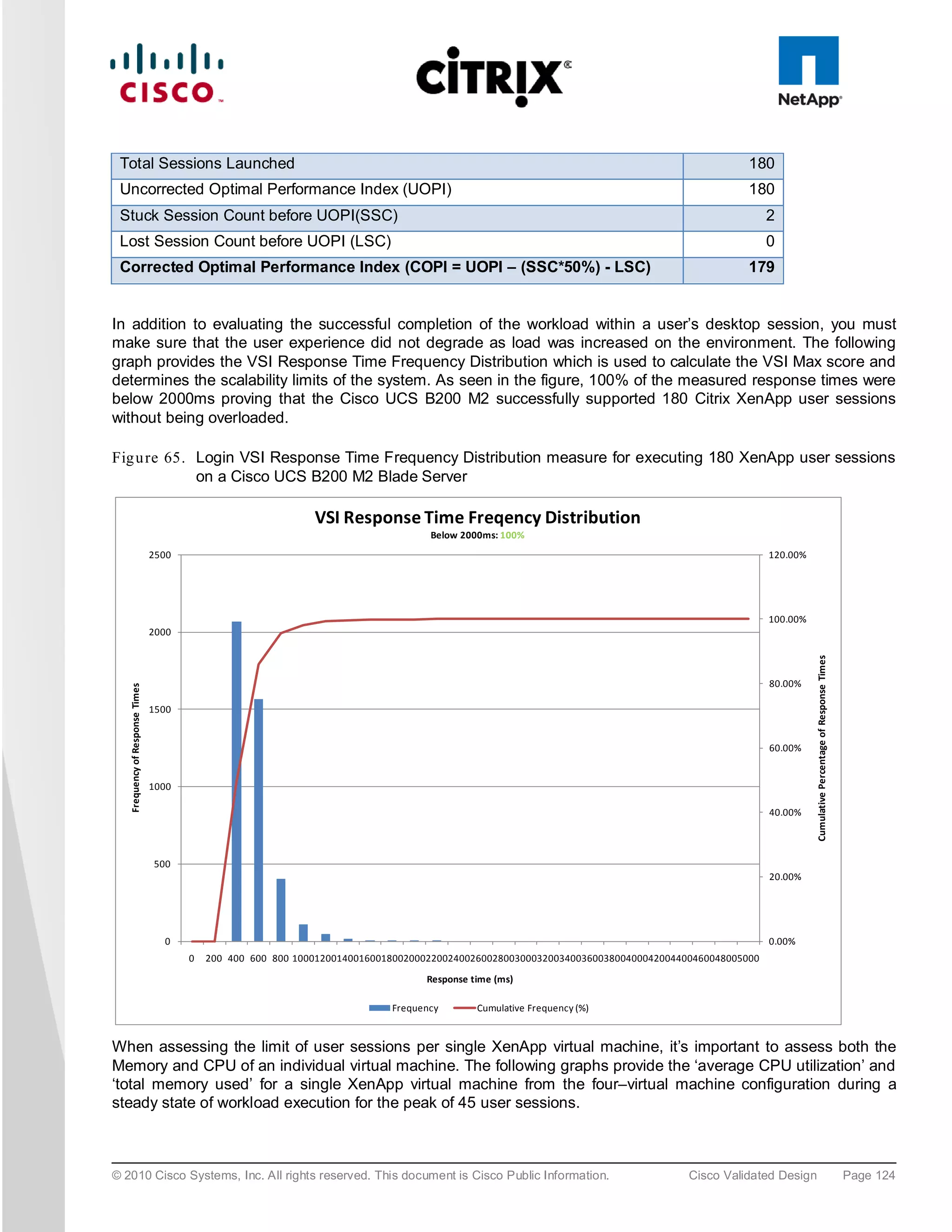
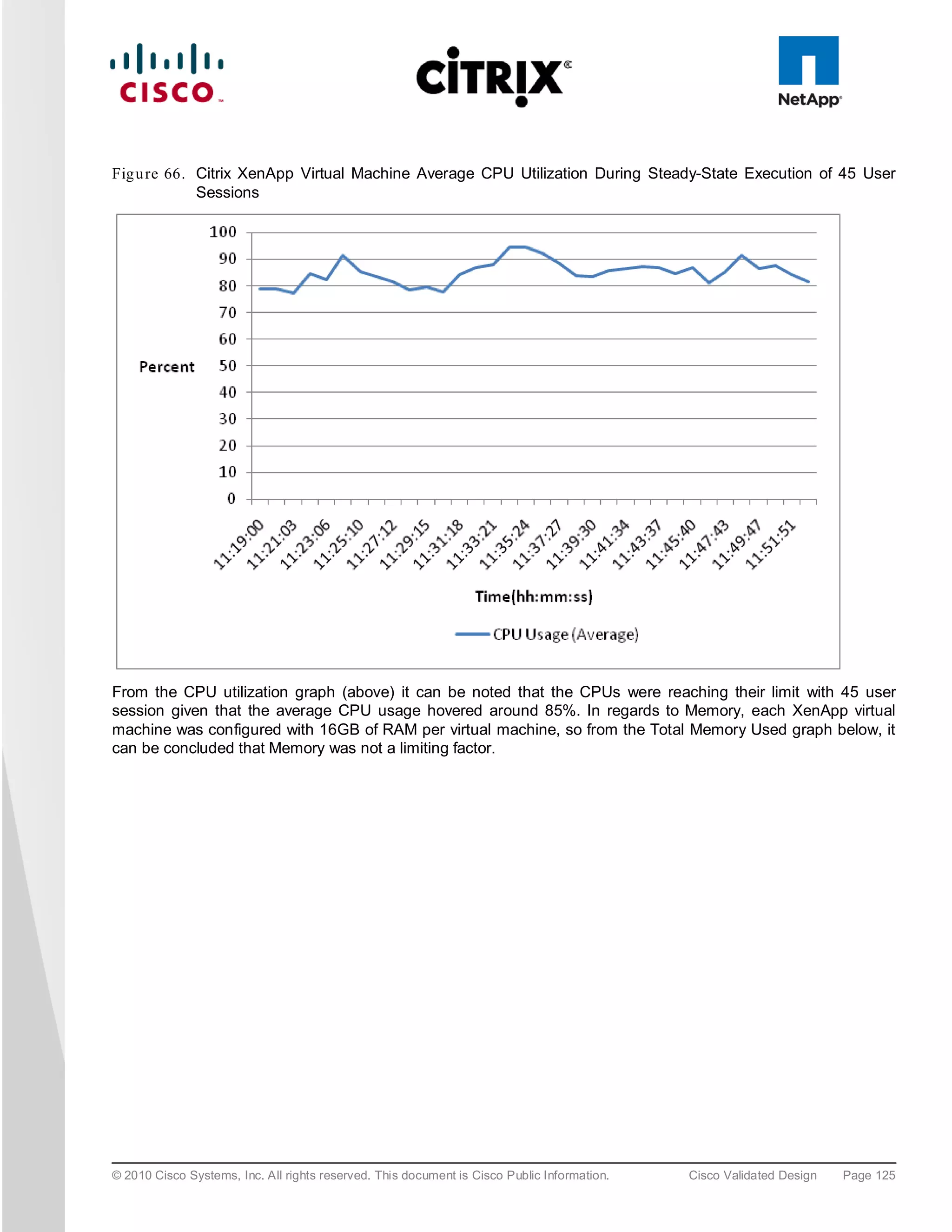
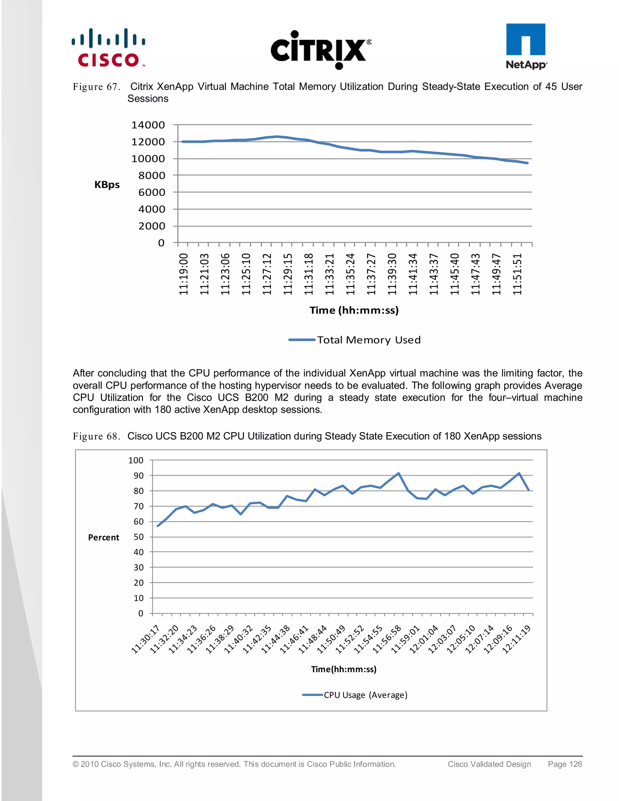
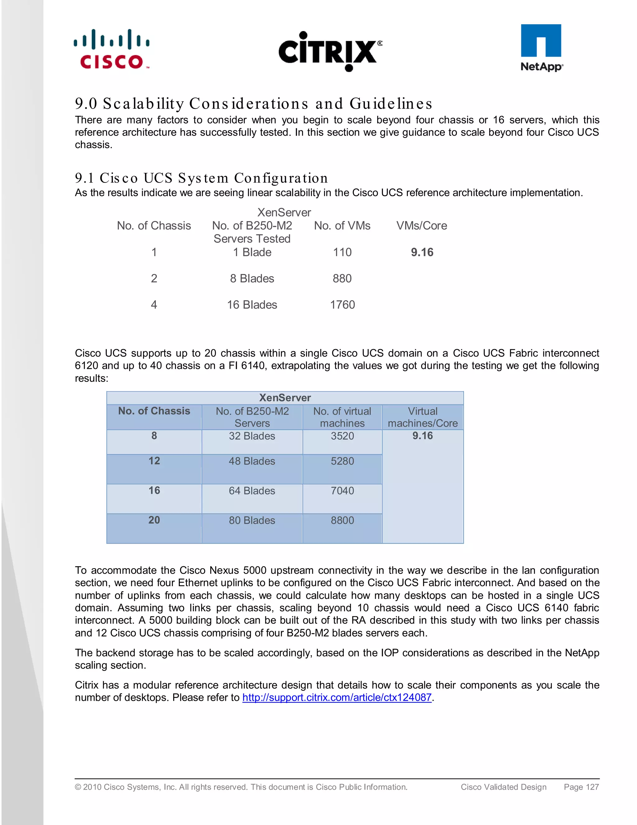
The document evaluates the scalability of Citrix XenDesktop on Cisco UCS B-series blade servers connected to NetApp storage, providing best practice recommendations for large-scale deployments. It reports successful validation of hosted VDI and shared desktops, highlighting effective memory configurations that enable high-density desktop sessions with linear scalability observed between different server configurations. Additionally, it emphasizes the advantages of Cisco's unified computing system in terms of performance, management, and infrastructure simplicity.
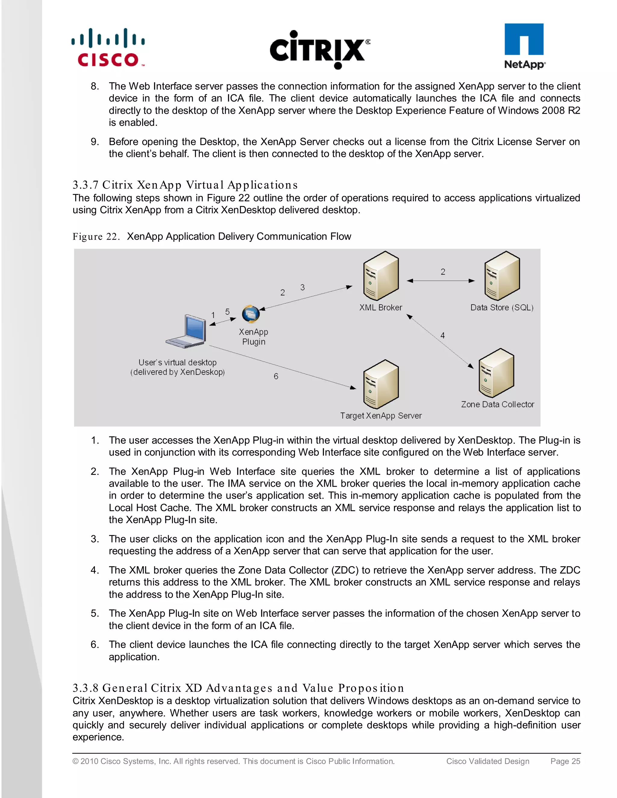
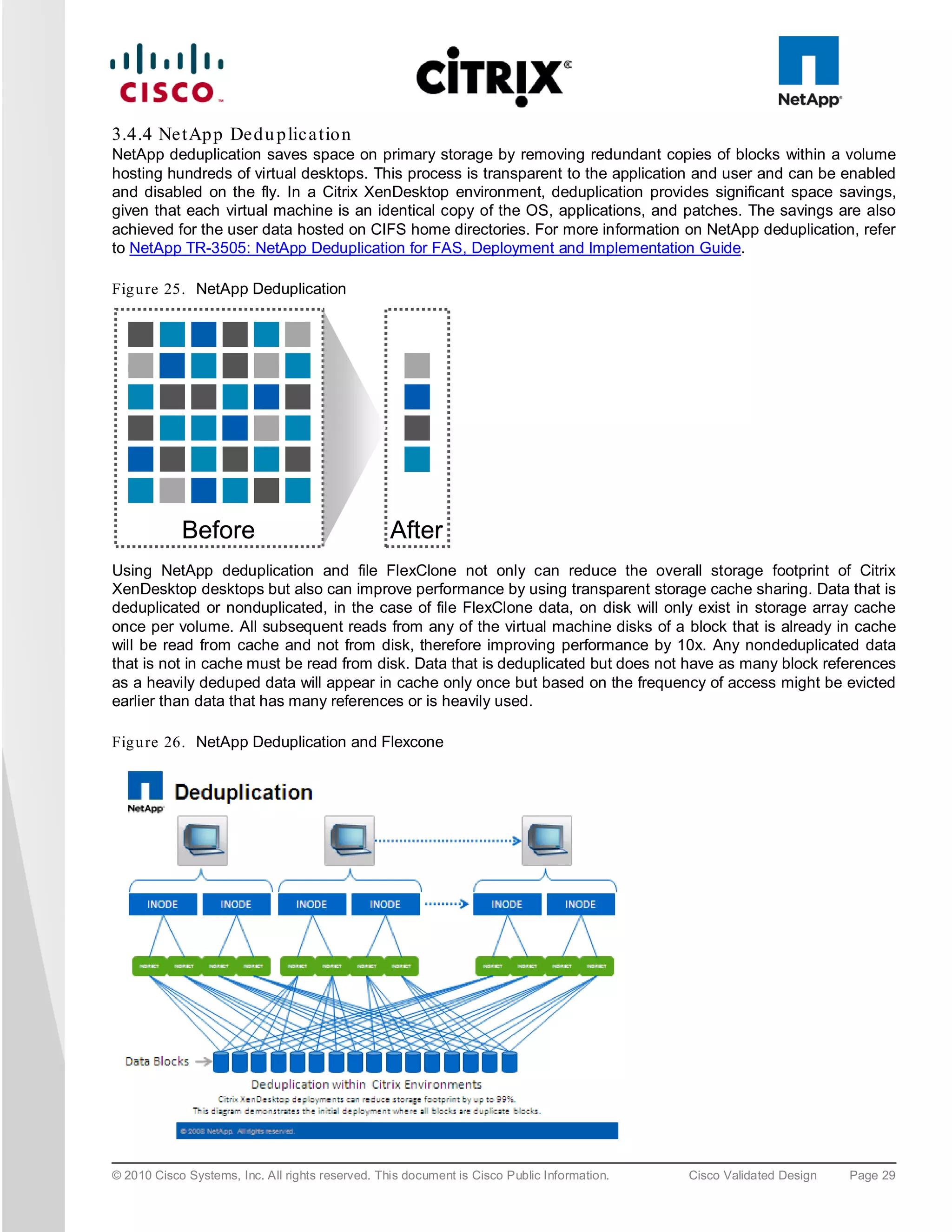
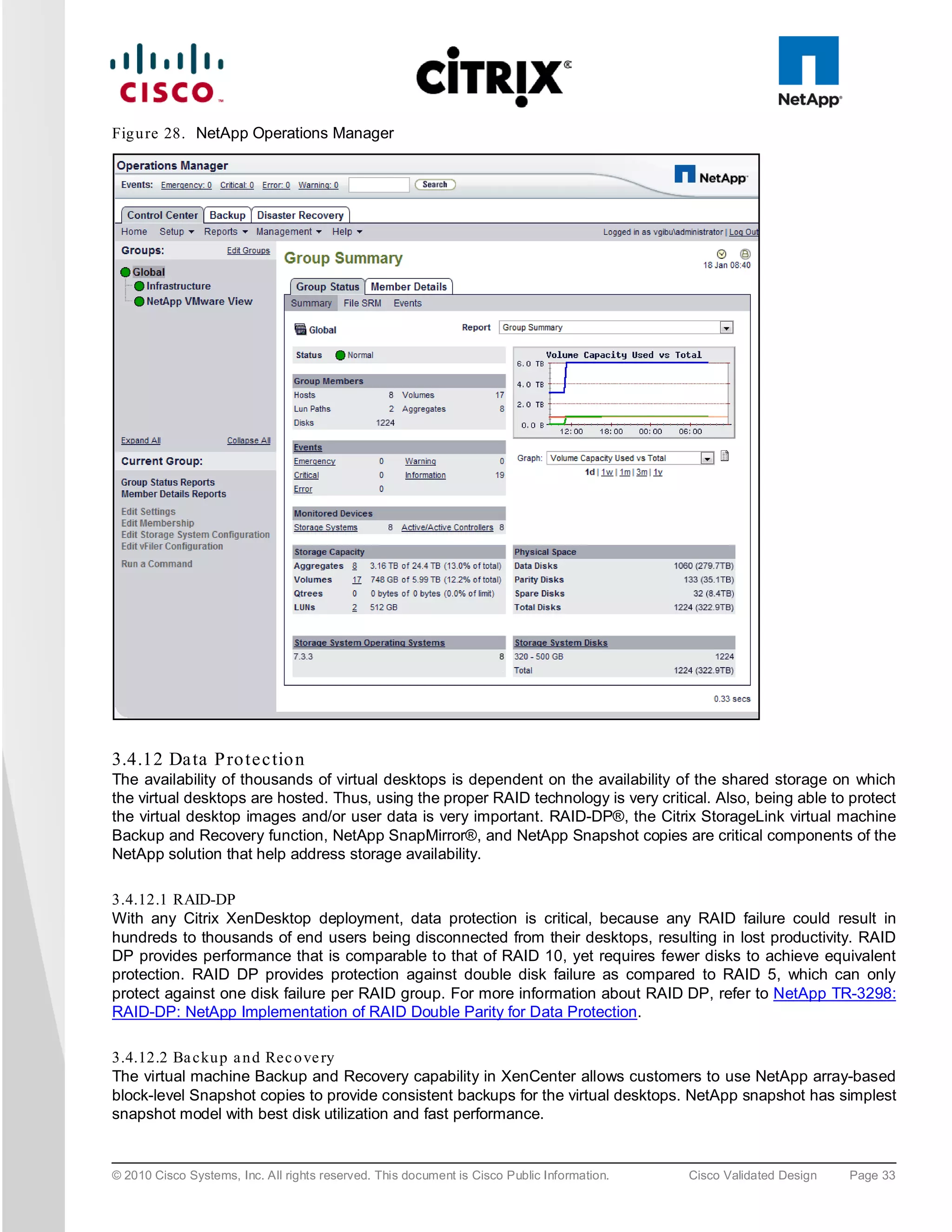
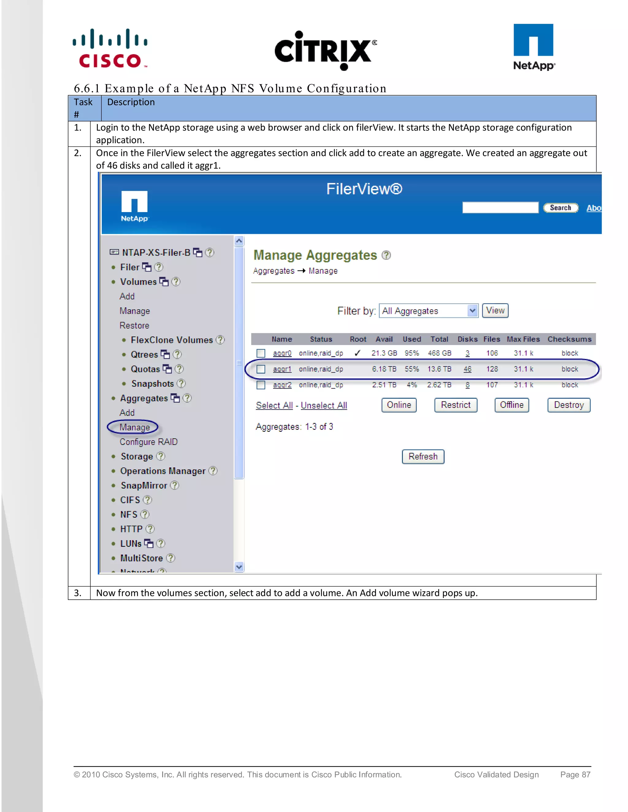
![3.5.2 Cis c o Ne xu s 5000 S e rie s Fe a tu re Hig h lig h ts
3.5.2.1 Fea tu re s a n d Be n e fits
The switch family's rich feature set makes the series ideal for rack-level, access-layer applications. It protects
investments in data center racks with standards based Ethernet and FCoE features that allow IT departments to
consolidate networks based on their own requirements and timing.
● The combination of high port density, wire-speed performance, and extremely low latency makes the switch
an ideal product to meet the growing demand for 10 Gigabit Ethernet at the rack level. The switch family
has sufficient port density to support single or multiple racks fully populated with blade and rack-mount
servers.
● Built for today’s data centers, the switches are designed just like the servers they support. Ports and power
connections are at the rear, closer to server ports, helping keep cable lengths as short and efficient as
possible. Hot-swappable power and cooling modules can be accessed from the front panel, where status
lights offer an at-a-glance view of switch operation. Front-to-back cooling is consistent with server designs,
supporting efficient data center hot- and cold-aisle designs. Serviceability is enhanced with all customer-
replaceable units accessible from the front panel. The use of SFP+ ports offers increased flexibility to use a
range of interconnect solutions, including copper for short runs and fiber for long runs.
● Fibre Channel over Ethernet and IEEE Data Center Bridging features supports I/O consolidation, eases
management of multiple traffic flows, and optimizes performance. Although implementing SAN
consolidation requires only the lossless fabric provided by the Ethernet pause mechanism, the Cisco Nexus
5000 Series provides additional features that create an even more easily managed, high-performance,
unified network fabric.
3.5.2.2 10 Giga b it Eth e rne t an d Un ifie d Fa b ric Fe a tu re s
The Cisco Nexus 5000 Series is first and foremost a family of outstanding access switches for 10 Gigabit Ethernet
connectivity. Most of the features on the switches are designed for high performance with 10 Gigabit Ethernet.
The Cisco Nexus 5000 Series also supports FCoE on each 10 Gigabit Ethernet port that can be used to
implement a unified data center fabric, consolidating LAN, SAN, and server clustering traffic.
3.5.2.3 Low La te nc y
The cut-through switching technology used in the Cisco Nexus 5000 Series ASICs enables the product to offer a
low latency of 3.2 microseconds, which remains constant regardless of the size of the packet being switched. This
latency was measured on fully configured interfaces, with access control lists (ACLs), quality of service (QoS),
and all other data path features turned on. The low latency on the Cisco Nexus 5000 Series enables application-
to-application latency on the order of 10 microseconds (depending on the network interface card [NIC]). These
numbers, together with the congestion management features described next, make the Cisco Nexus 5000 Series
a great choice for latency-sensitive environments.
Other features include: Nonblocking Line-Rate Performance, Single-Stage Fabric, Congestion Management,
Virtual Output Queues, Lossless Ethernet (Priority Flow Control), Delayed Drop Fibre Channel over Ethernet,
Hardware-Level I/O Consolidation, and End-Port Virtualization. For more information, refer to
http://www.cisco.com/en/US/products/ps9670/prod_white_papers_list.html.
3.6 Mic ros o ft Win d o ws 7
Microsoft introduced Windows 7 in fall of 2009 as their next generation desktop operating system to succeed
Windows XP, their other flagship software. According to IDC report around 70 percent of the enterprise users are
using Windows XP and a majority of them are already looking to migrate to Windows 7.
© 2010 Cisco Systems, Inc. All rights reserved. This document is Cisco Public Information. Cisco Validated Design Page 39](https://image.slidesharecdn.com/ucsxdxenserverntap-110704045224-phpapp01/75/Cisco-Virtualization-Experience-Infrastructure-39-2048.jpg)
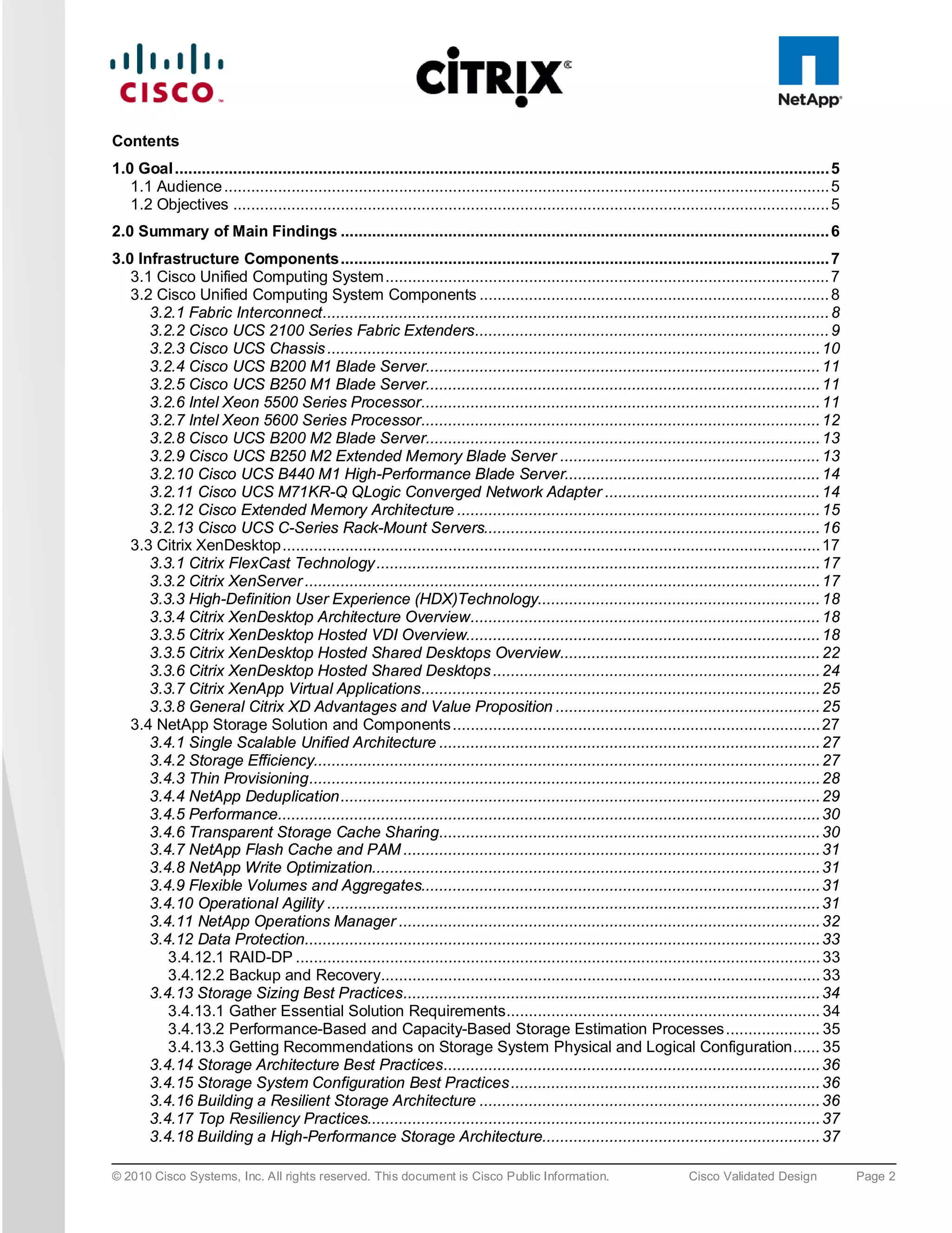
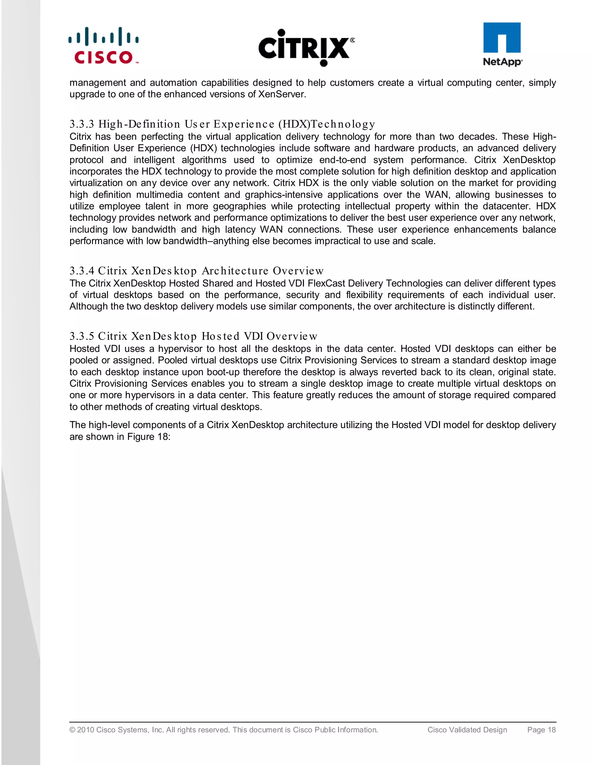
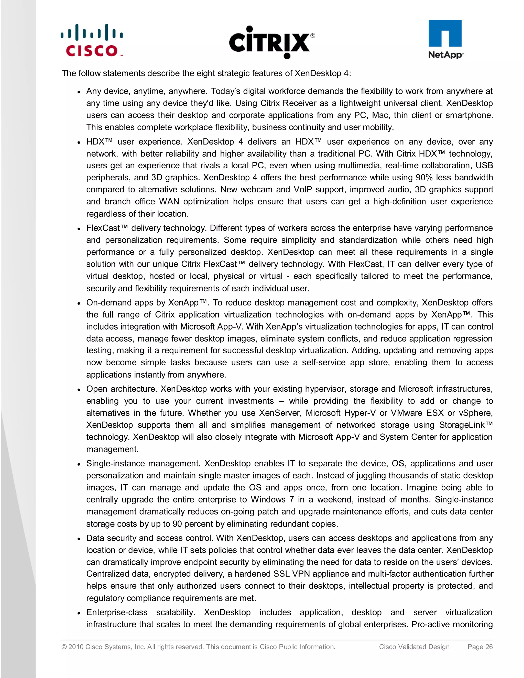
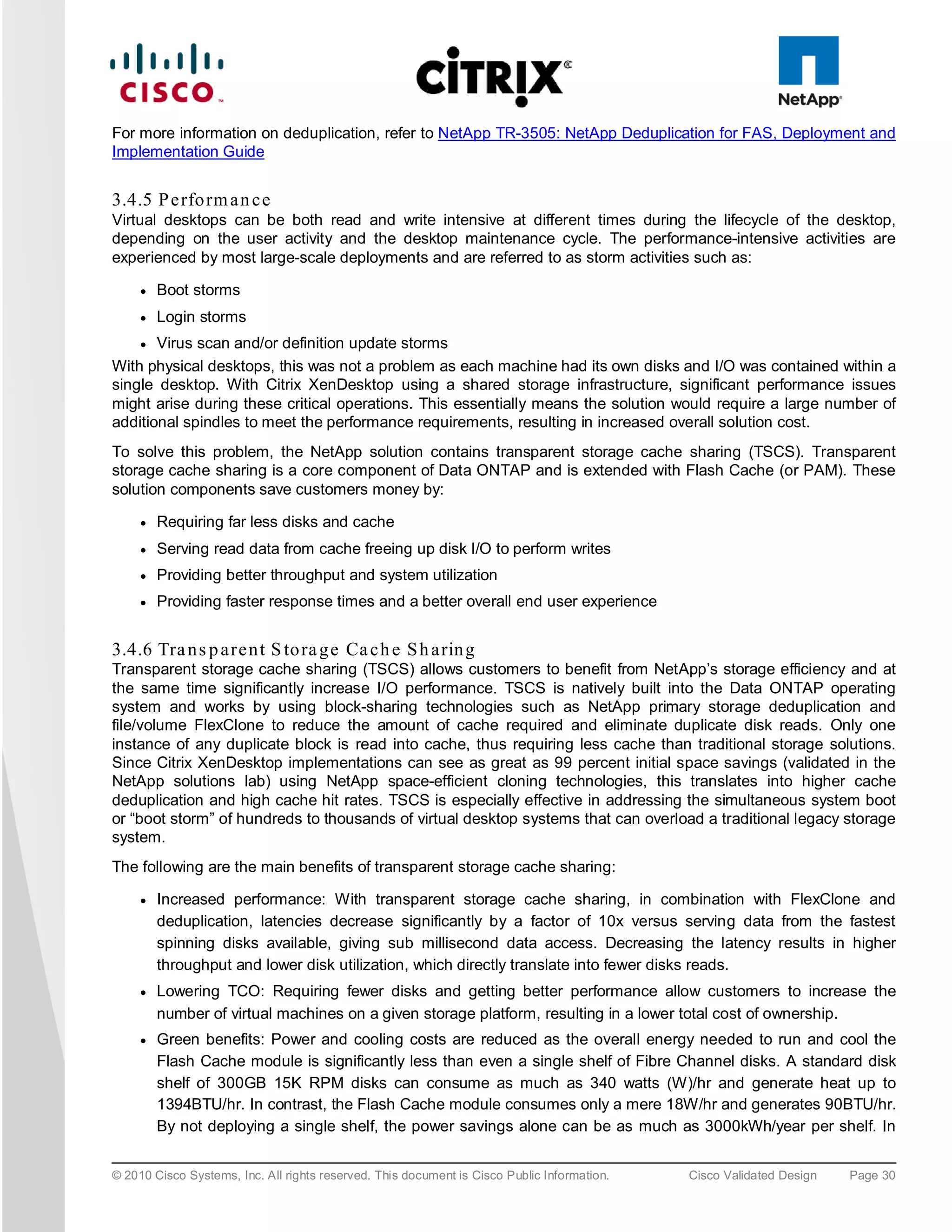
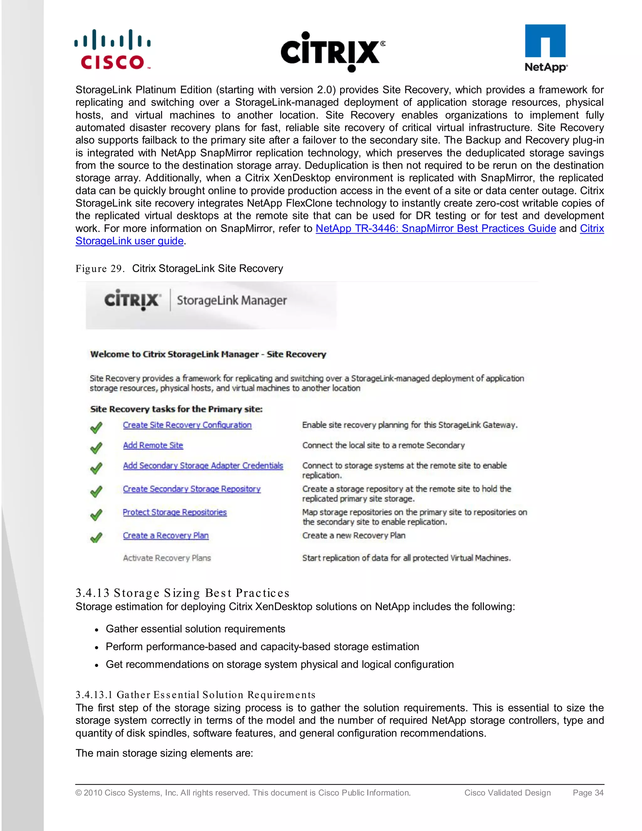
![Set device to boot from hard disk
6. Boot Windows 7 virtual machine and check vDisk is attached.
To clone Windows 7 Image to vDisk:
1. To retain the 1024 partition offset in the vDisk the following needs to be added to the C:Program
FilesCitrixXenConvert.ini:
[parameters]
PartitionOffsetBase=1048576
2. Run XenConvert
3. Run PVS Device Optimization Tool by clicking the Optimize button.
4. Image to assigned vDisk (E:).
5. Once the Imaging process has completed shutdown the virtual machine.
To set the virtual machine to boot from PVS vDisk (rather than vDisk) and start virtual machine:
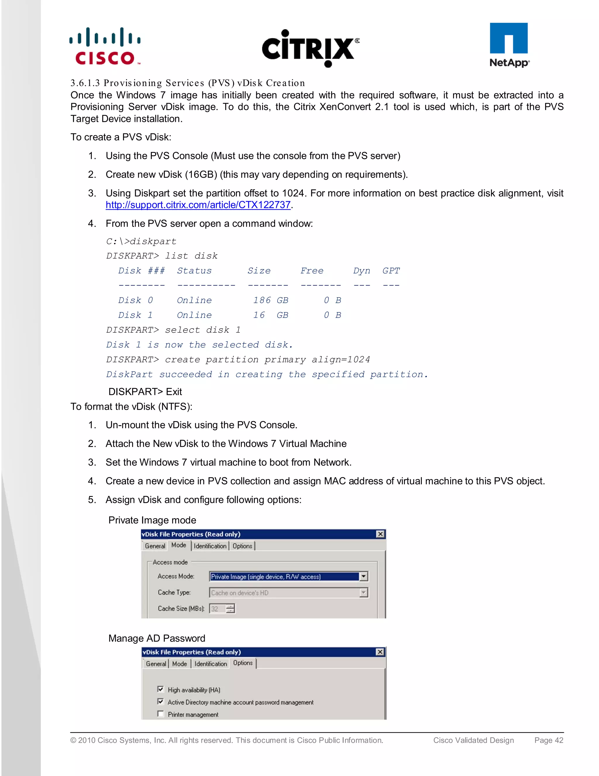
1. Use the PVS Console to change the Target device options to “boot from vDisk.”
© 2010 Cisco Systems, Inc. All rights reserved. This document is Cisco Public Information. Cisco Validated Design Page 43](https://image.slidesharecdn.com/ucsxdxenserverntap-110704045224-phpapp01/75/Cisco-Virtualization-Experience-Infrastructure-43-2048.jpg)

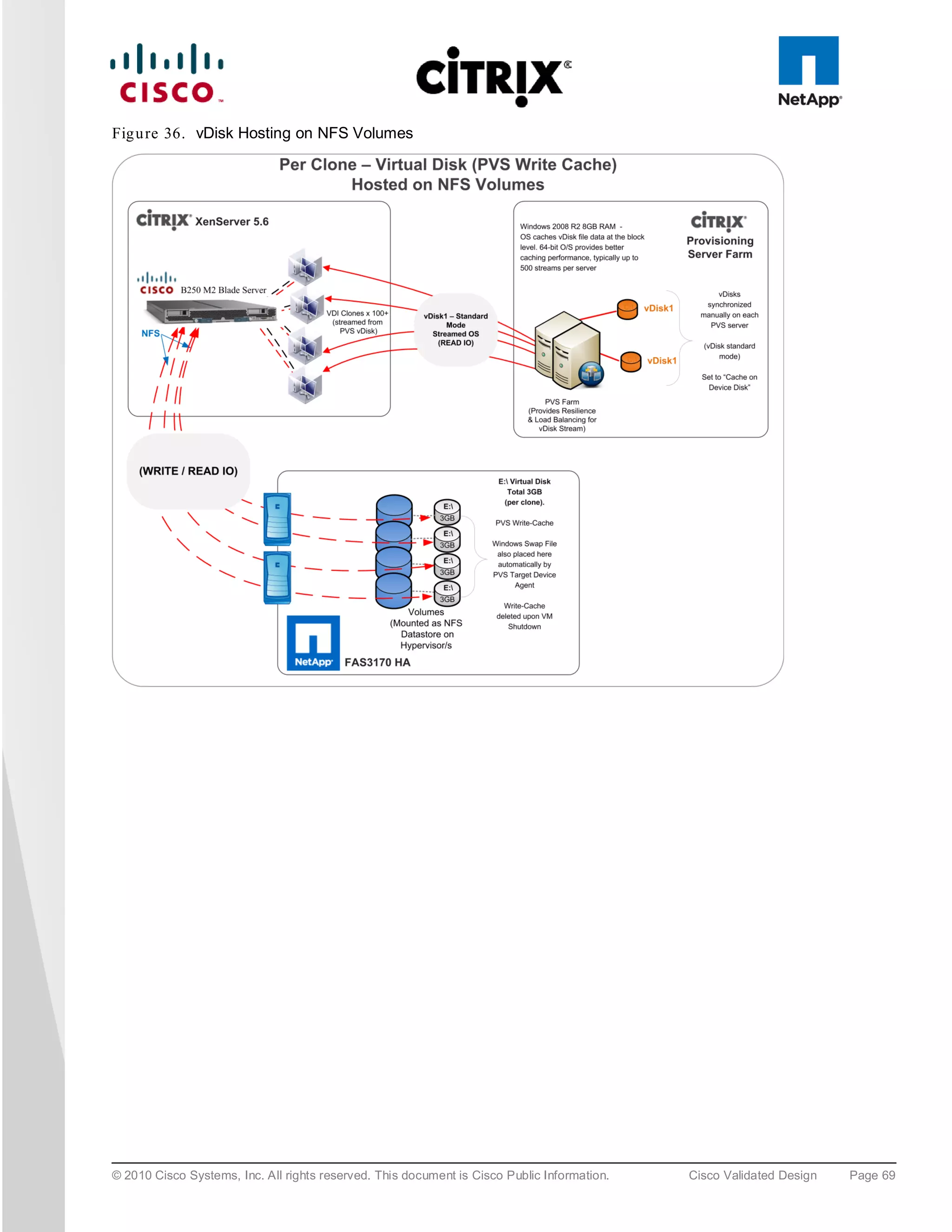
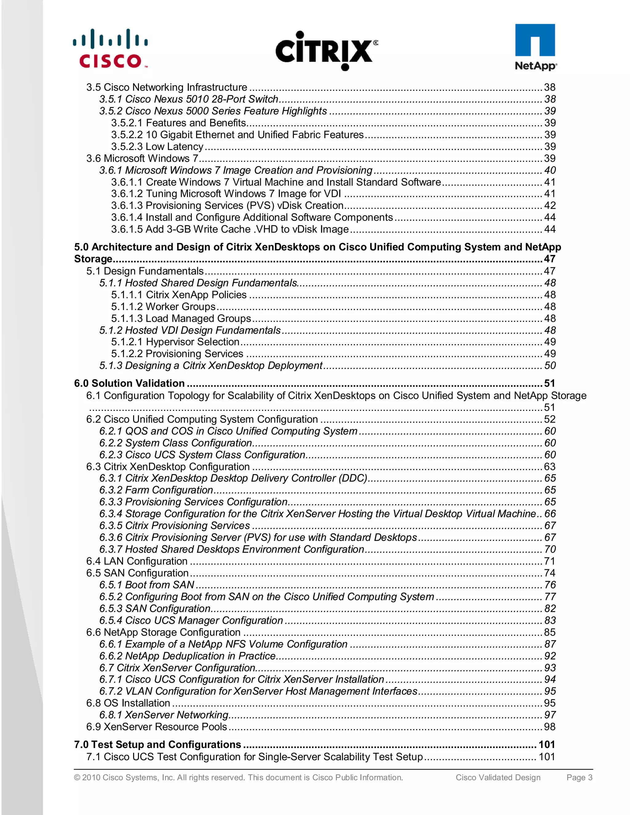
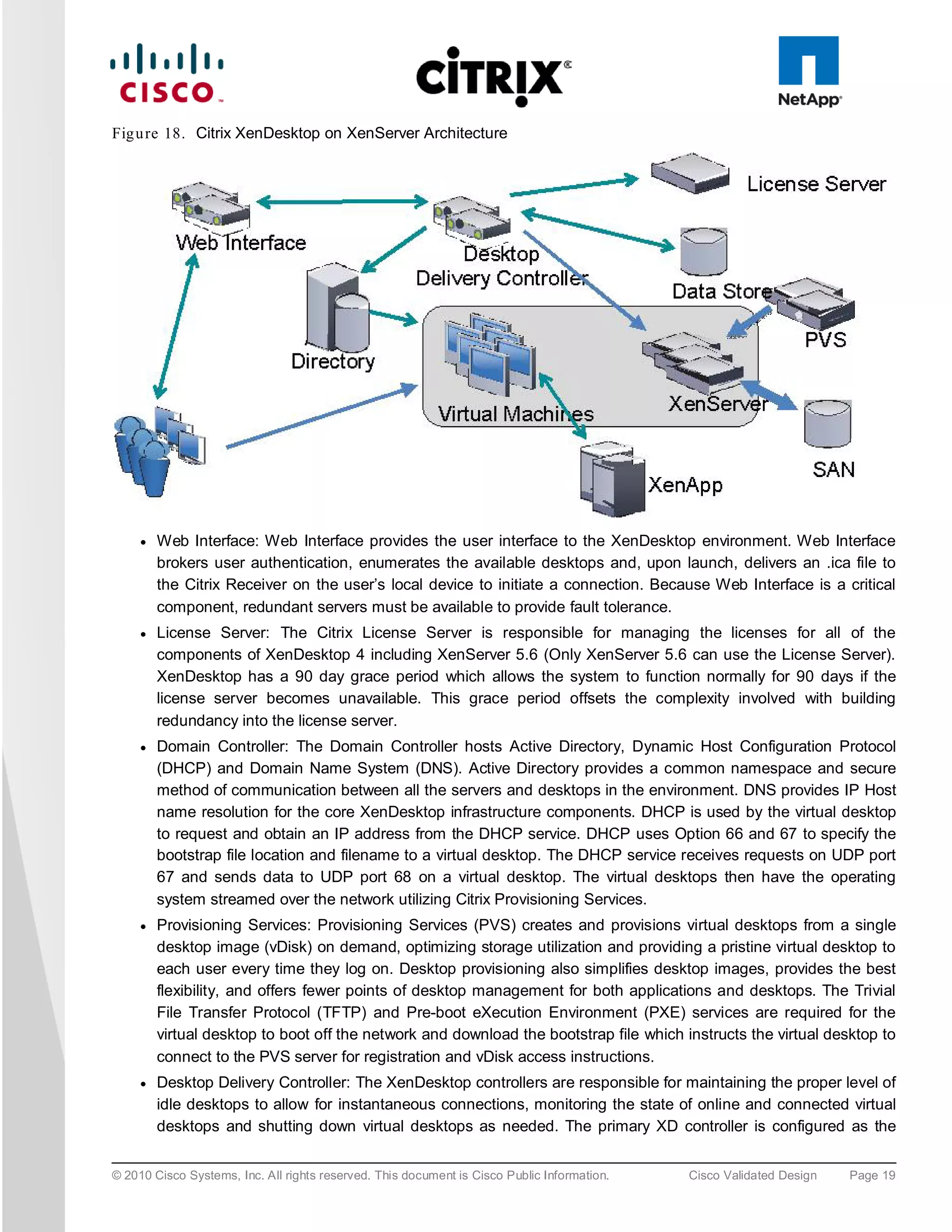
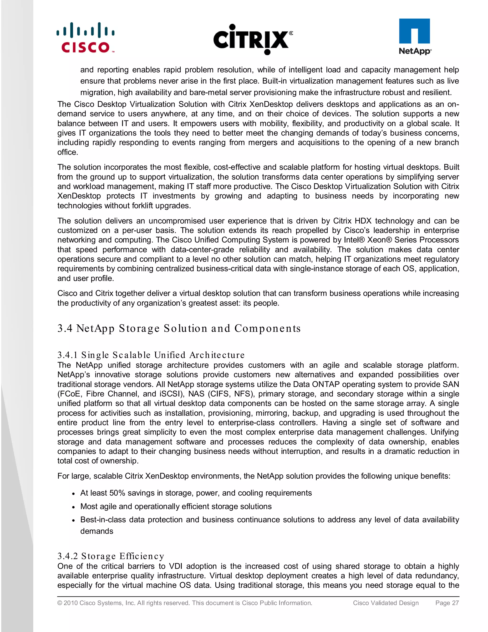
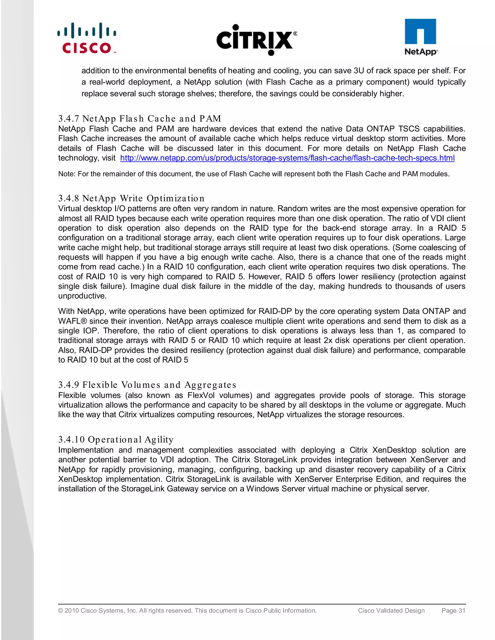
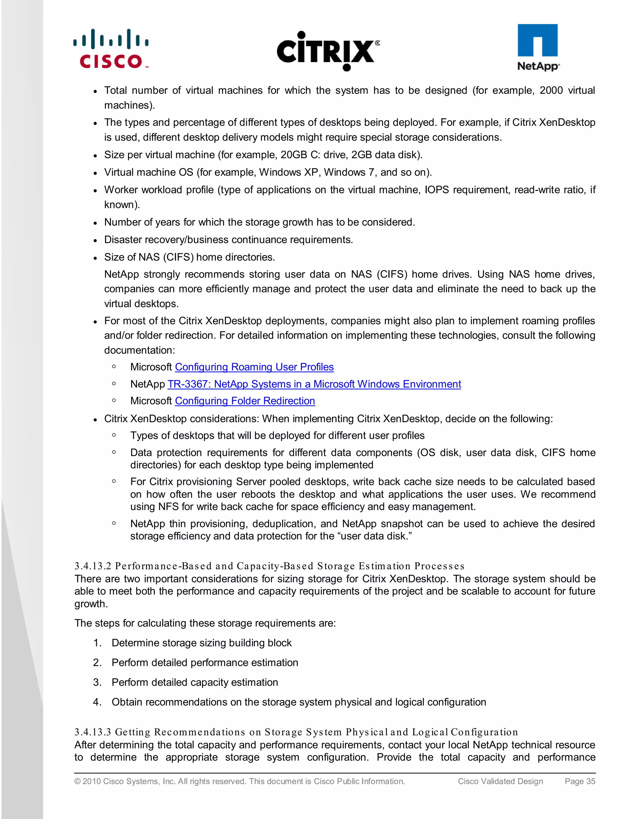
![Fig u re 38. Optimization for Virtualizing Citrix XenApp on Citrix XenServer
● Cisco UCS B200 M2 Blade Server. Cisco UCS B200 M2 blade server with two Intel Xeon 5600 Series
processors and 96GB of DDR3 memory was utilized for the testing.
● NetApp FAS3140 Filer. A dedicated Storage Repository over a Fibre Channel LUN on NetApp FAS3140
Filer was used for storing data for all virtualized workloads in the environment, including the Citrix XenApp
virtual machines.
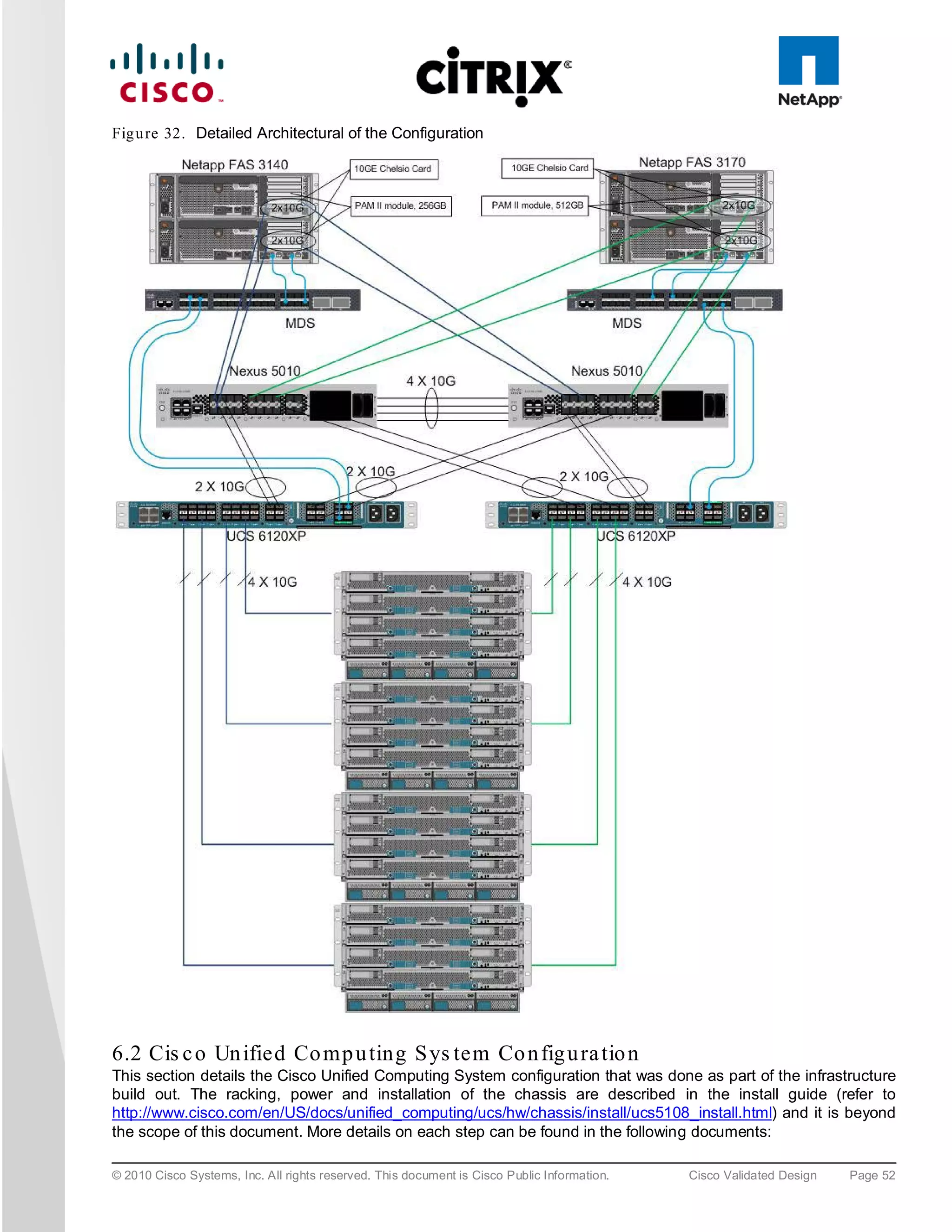
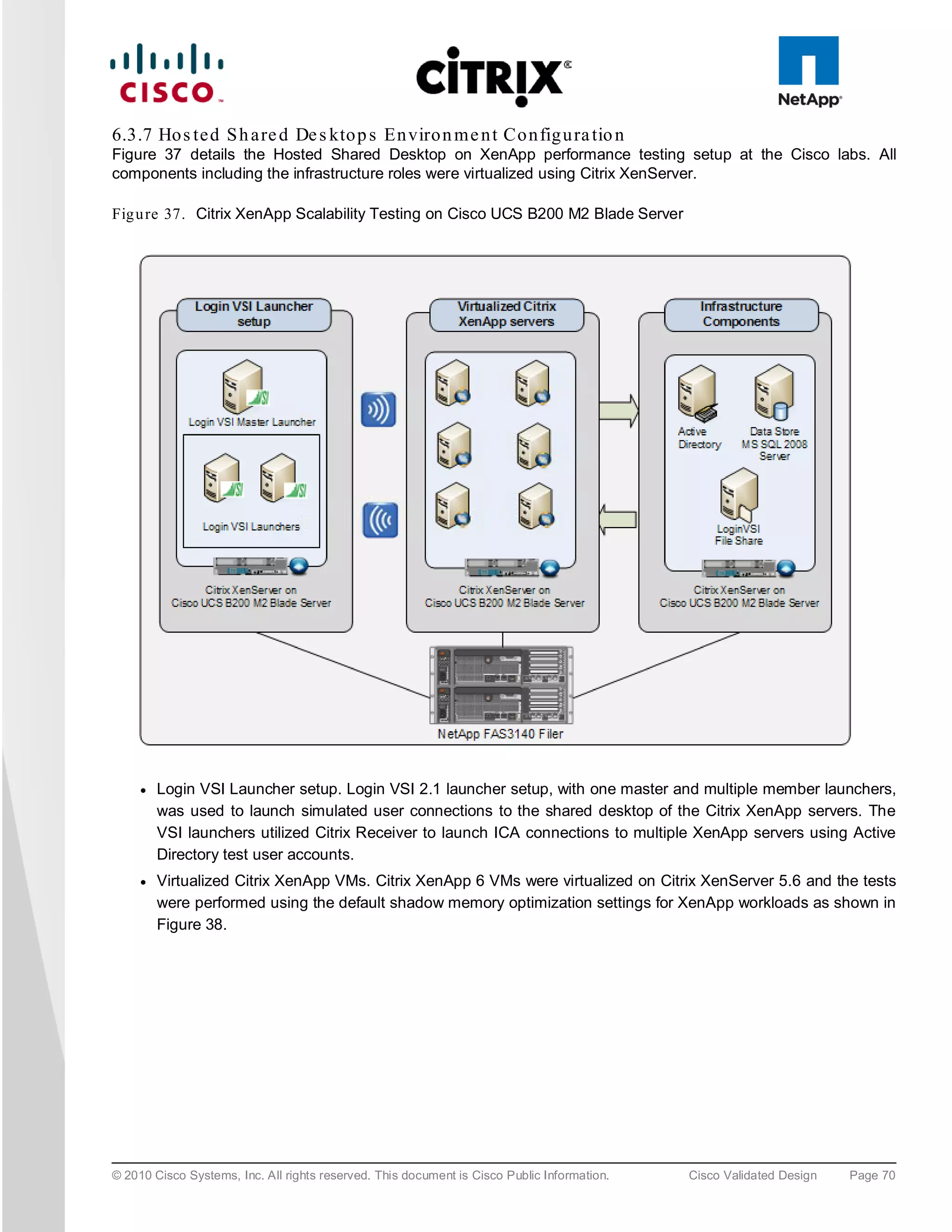
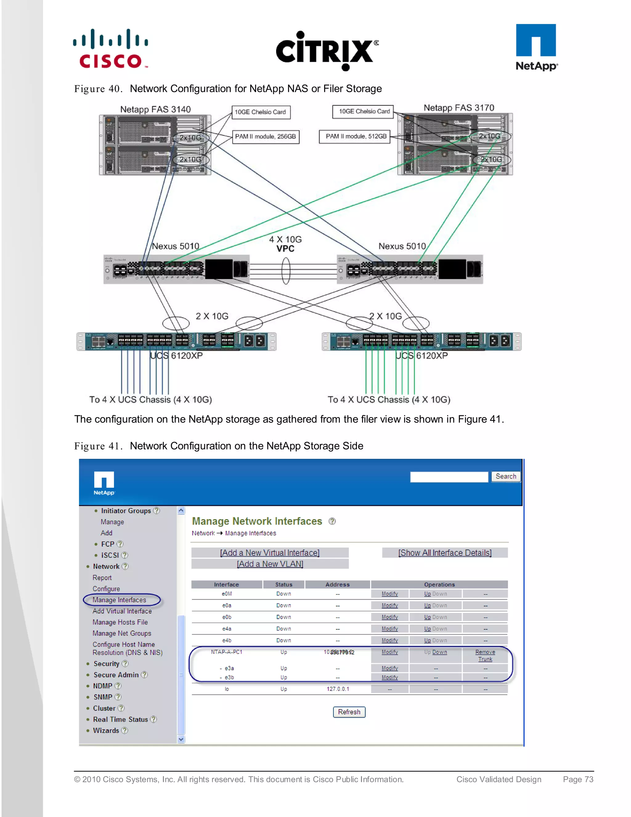
6.4 LAN Co n figu ra tion
This configuration consists of a pair of Cisco Nexus 5010, a family of low-latency, line-rate, 10 Gigabit Ethernet
and FCoE switches for data center applications. Four 10 Gigabit Ethernet uplink ports are configured on each of
the Cisco UCS fabric interconnects, and they are connected to the Cisco Nexus 5010 pair in a bow tie manner as
shown below. The Fabric interconnect is in End host mode, as we are doing both Fibre Channel as well as
Ethernet data access and as per the recommended best practice of the Cisco Unified Computing System. We
built this out for scale and have provisioned more than 40 G per Fabric interconnect as we are building a scalable
and expandable system (Figure 39).
The upstream configuration is beyond the scope of this document; there are some good reference document [4]
that talks about best practices of using the Cisco Nexus 5000 and 7000 Series Switches.
© 2010 Cisco Systems, Inc. All rights reserved. This document is Cisco Public Information. Cisco Validated Design Page 71](https://image.slidesharecdn.com/ucsxdxenserverntap-110704045224-phpapp01/75/Cisco-Virtualization-Experience-Infrastructure-71-2048.jpg)
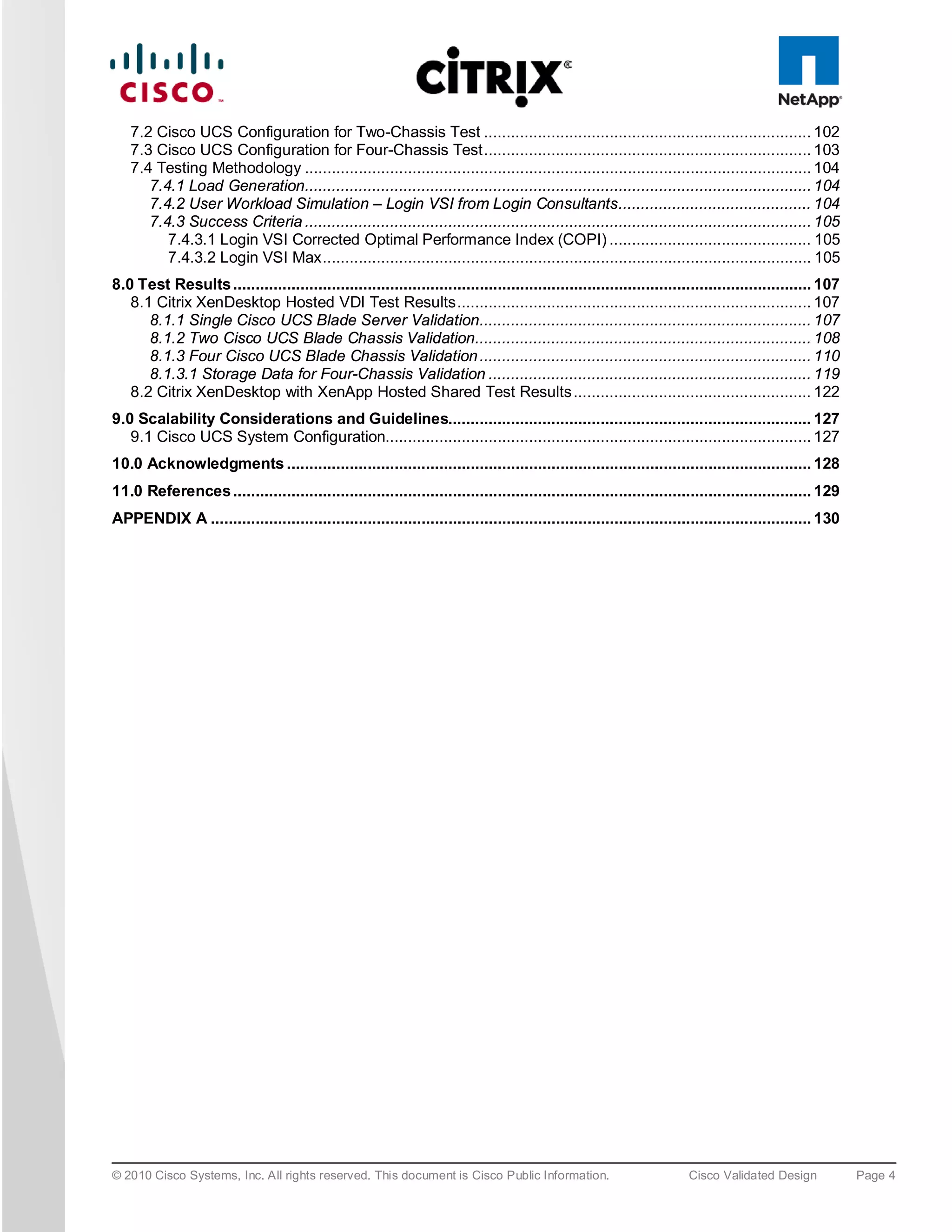
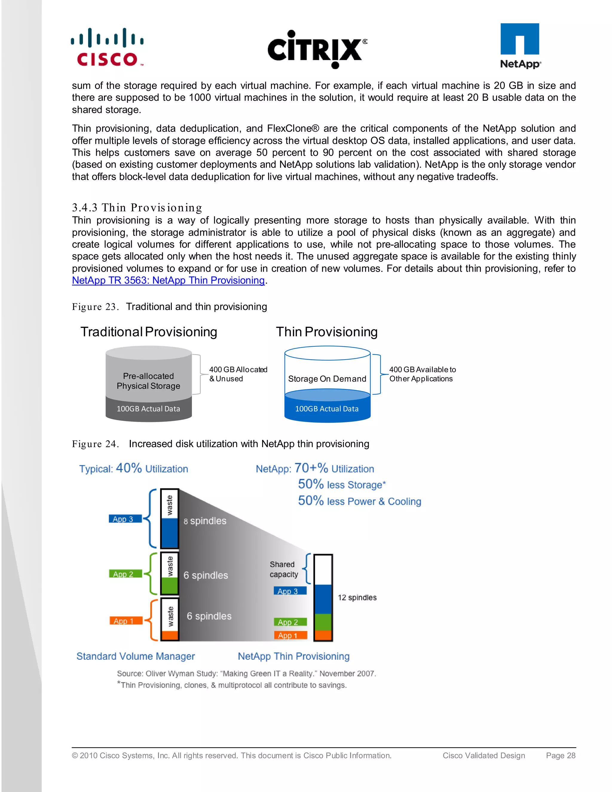
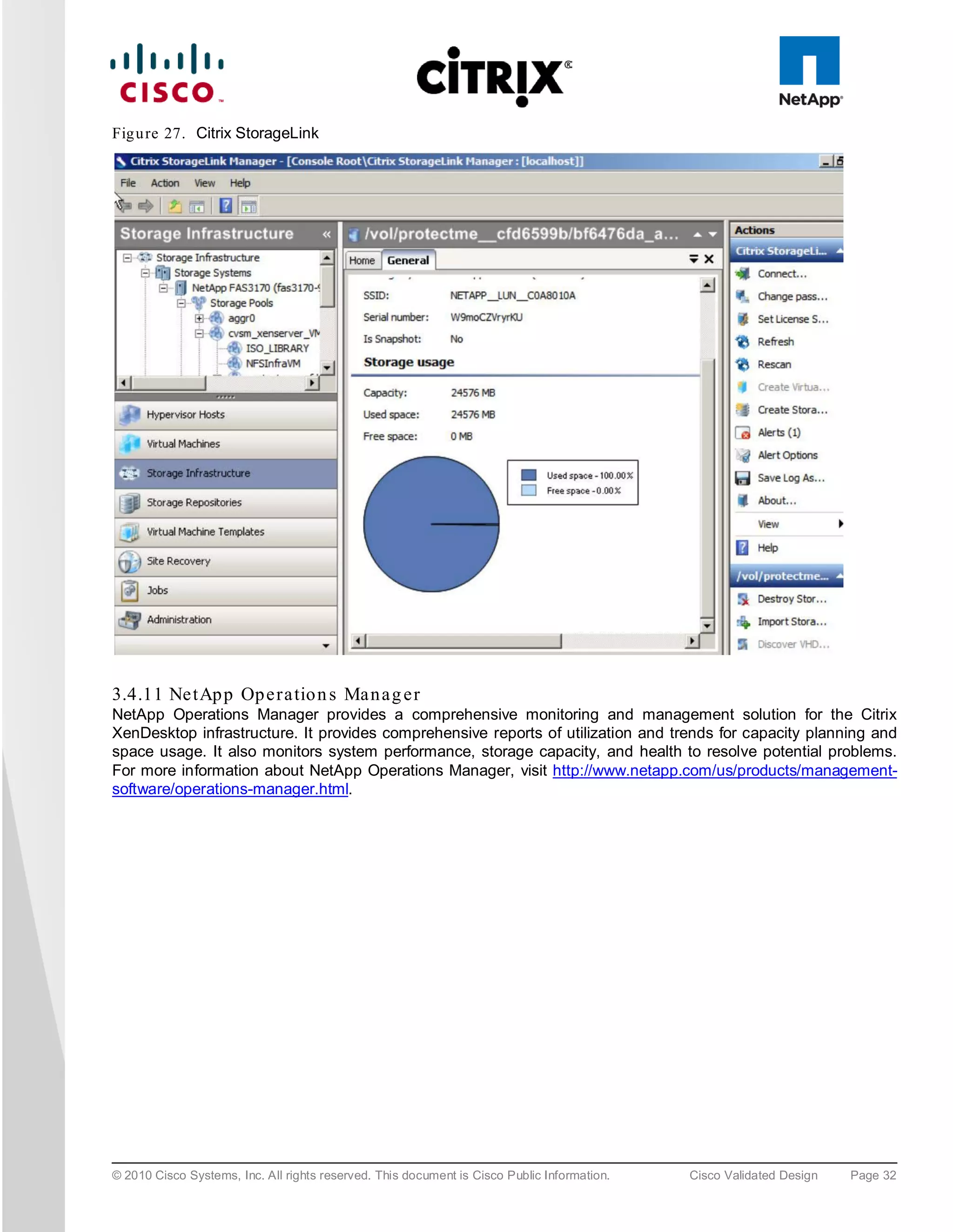
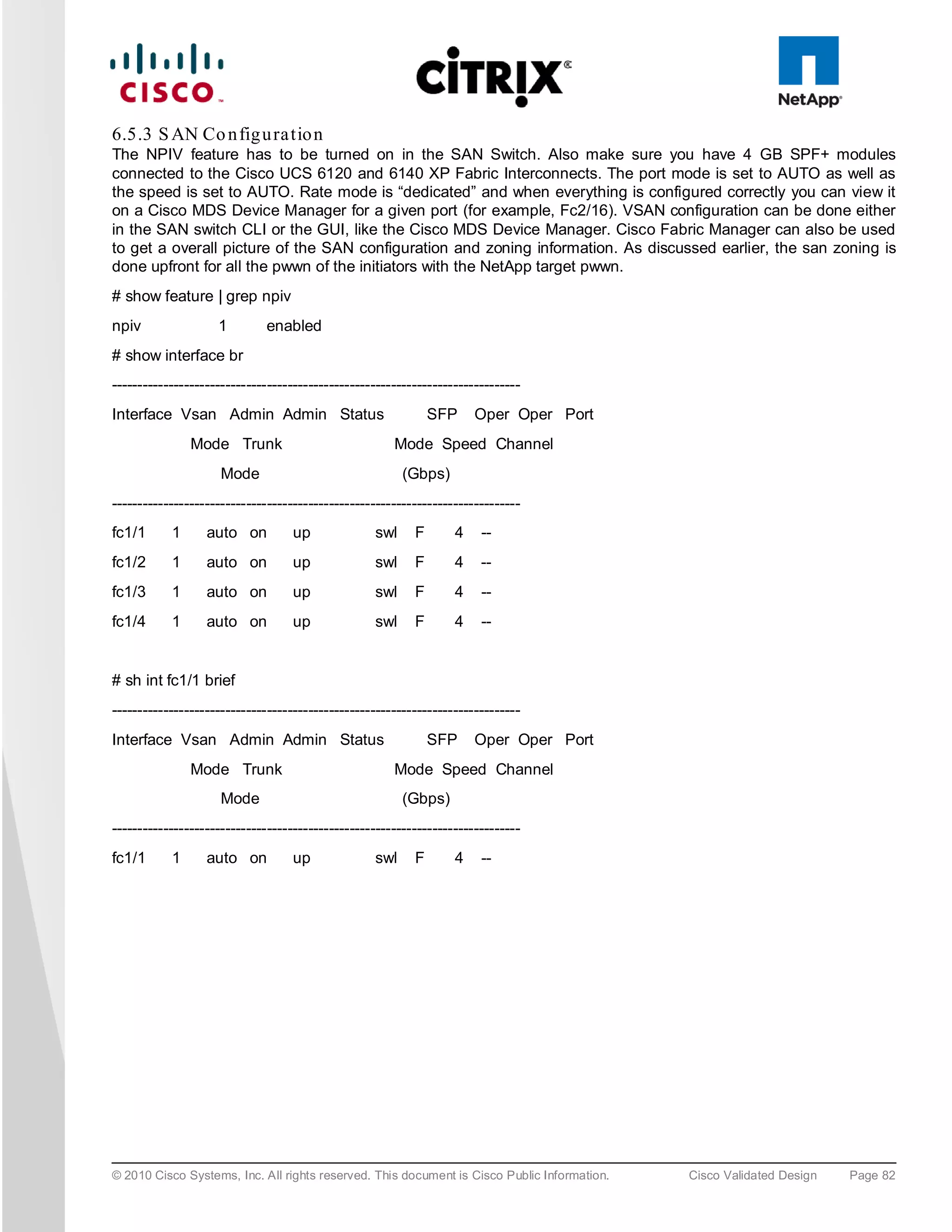
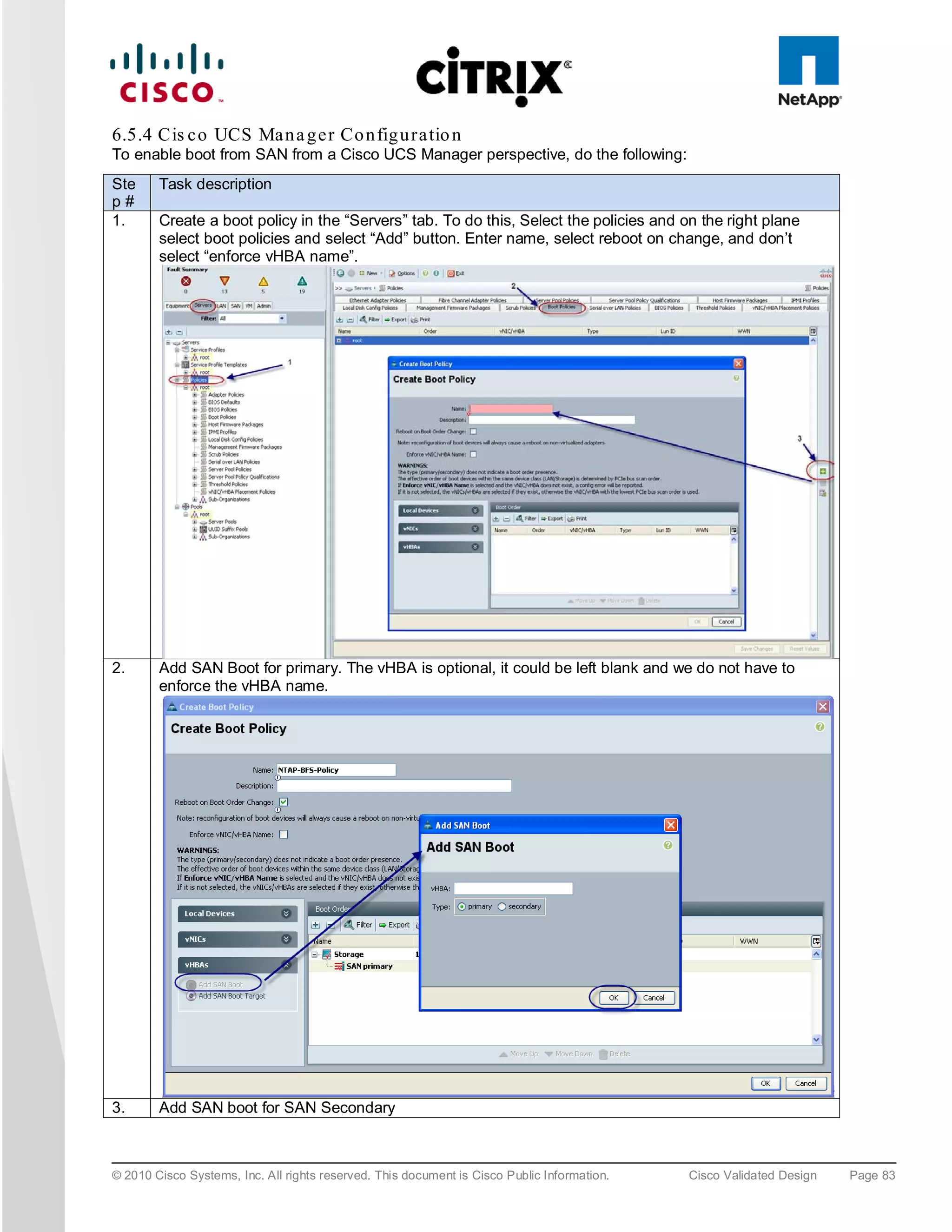
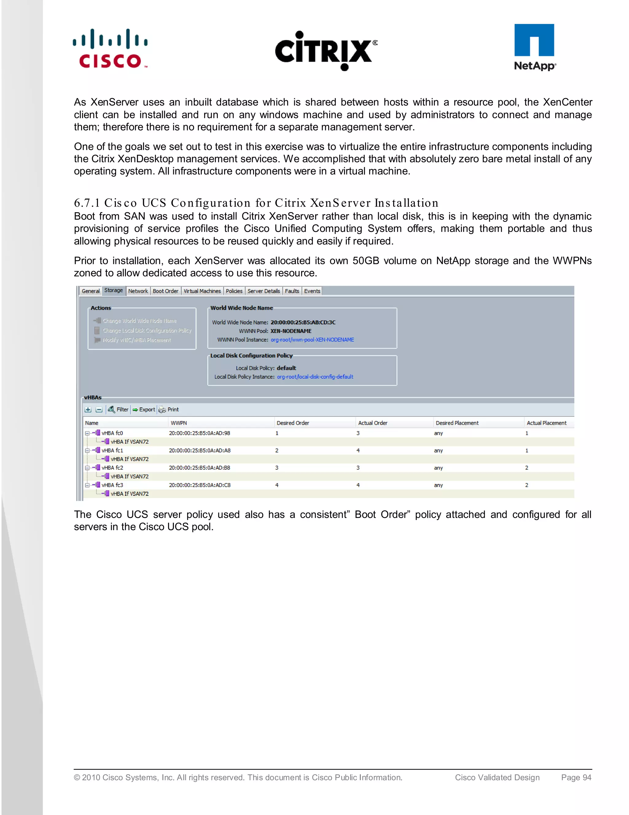
![6.5 S AN Co n fig u ra tio n
A pair of Cisco MDS 9134 Multilayer Fabric Switches were used in the configuration to connect to the Fibre
Channel port of the Cisco UCS fabric interconnect Fibre Channel expansion module ports to the NetApp storage
Fibre Channel ports. A Cisco MDS 9000 Family single initiator zone was used to connect to the NetApp Fibre
Channel ports. The SAN switch was predominantly used for configuring boot from SAN of the XenServer server
blades.
The infrastructure volumes were block based and the zoning was done to make those NetApp LUNs visible to the
infrastructure and test servers. An example SAN zone configuration is shown below on the Fabric A side:
MDS-A# sh zoneset active vsan 1
zoneset name FAB-A-XD-XS-BFS vsan 1
zone name XD-Xen-Server-1-fc0 vsan 1
* fcid 0x470133 [pwwn 20:00:00:25:b5:0a:ad:3e]
* fcid 0x470200 [pwwn 50:0a:09:83:89:1a:b9:d9]
* fcid 0x470300 [pwwn 50:0a:09:81:89:1a:b9:d9]
© 2010 Cisco Systems, Inc. All rights reserved. This document is Cisco Public Information. Cisco Validated Design Page 74](https://image.slidesharecdn.com/ucsxdxenserverntap-110704045224-phpapp01/75/Cisco-Virtualization-Experience-Infrastructure-74-2048.jpg)
![zone name XD-Xen-Server-2-fc0 vsan 1
* fcid 0x47002e [pwwn 20:00:00:25:b5:0a:ad:3c]
* fcid 0x470200 [pwwn 50:0a:09:83:89:1a:b9:d9]
* fcid 0x470300 [pwwn 50:0a:09:81:89:1a:b9:d9]
Where 20:00:00:25:b5:0a:ad:3e/20:00:00:25:b5:0a:ad:2e are server’s pwwn of the CNA that are part of the Fabric
A side. Similar zoning is done on the corresponding Cisco MDS 9000 Family switch pair to take care of the Fabric
B side as shown below.
MDS-B# sh zoneset active vsan 1
zoneset name FAB-B-XD-XS-BFS vsan 1
zone name XD-Xen-Server-1-fc1 vsan 1
* fcid 0x47002e [pwwn 20:00:00:25:b5:0a:ad:2e]
* fcid 0x470500 [pwwn 50:0a:09:81:99:1a:b9:d9]
* fcid 0x470400 [pwwn 50:0a:09:83:99:1a:b9:d9]
zone name XD-Xen-Server-2-fc1 vsan 1
* fcid 0x470735 [pwwn 20:00:00:25:b5:0a:ad:2c]
* fcid 0x470500 [pwwn 50:0a:09:83:99:1a:b9:d9]
* fcid 0x470400 [pwwn 50:0a:09:81:99:1a:b9:d9]
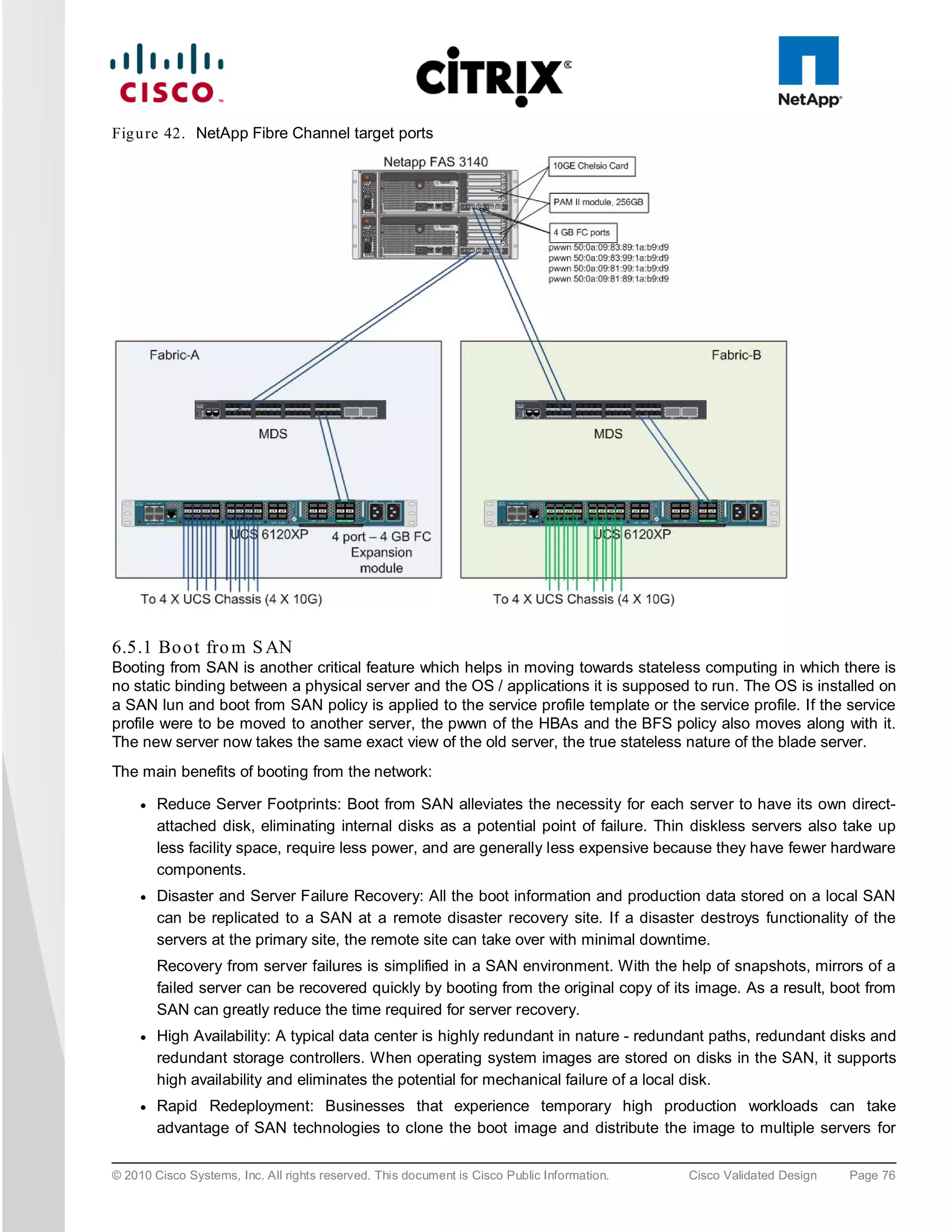
The NetApp Fibre Channel target ports, 50:0a:09:83:89:1a:b9:d9/50:0a:09:83:99:1a:b9:d9 belong to one
controller and 50:0a:09:81:99:1a:b9:d9/50:0a:09:81:89:1a:b9:d9 was part of the second controller. They were
spread across the two controllers for redundancy as shown in Figure 42.
© 2010 Cisco Systems, Inc. All rights reserved. This document is Cisco Public Information. Cisco Validated Design Page 75](https://image.slidesharecdn.com/ucsxdxenserverntap-110704045224-phpapp01/75/Cisco-Virtualization-Experience-Infrastructure-75-2048.jpg)
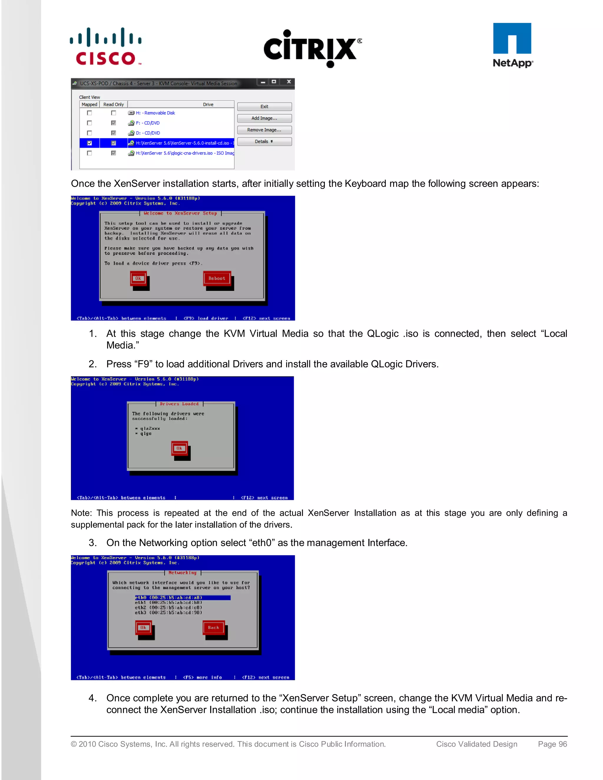
![5. To install XenServer on the SAN select any of the available “NetApp LUN” drives, i.e. “sdc – 50 GB
[NETAPP LUN]”.
6. At the end of the XenServer installation you are prompted for the QLogic driver supplemental pack;
connect the QLogic .iso using the KVM Virtual Media and select OK. Following the installation screens as
normal and when finished you will be prompted for any additional supplemental packs, if you have none
press skip to complete the installation.
Note: For XenDesktop the Linux supplemental pack is not required thus not installed, if required mount to Virtual media and
install.
7. Click “OK” to complete the installation and reboot the server.
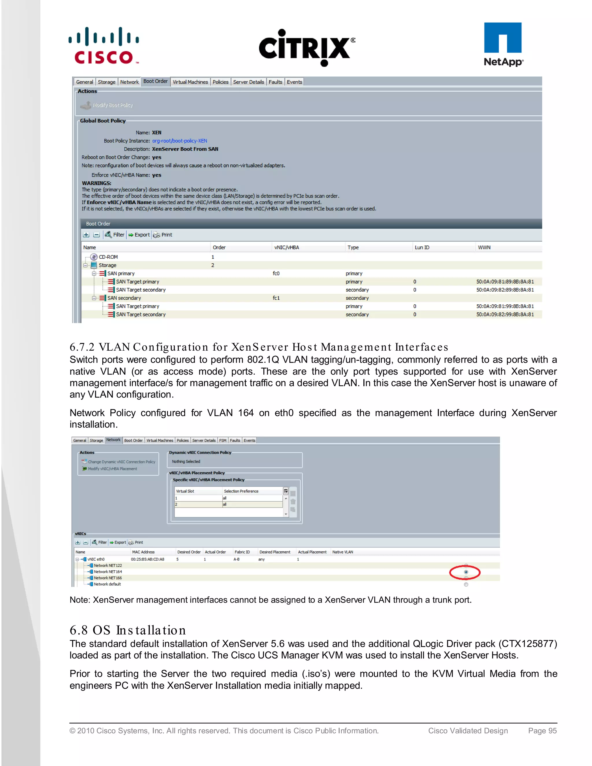
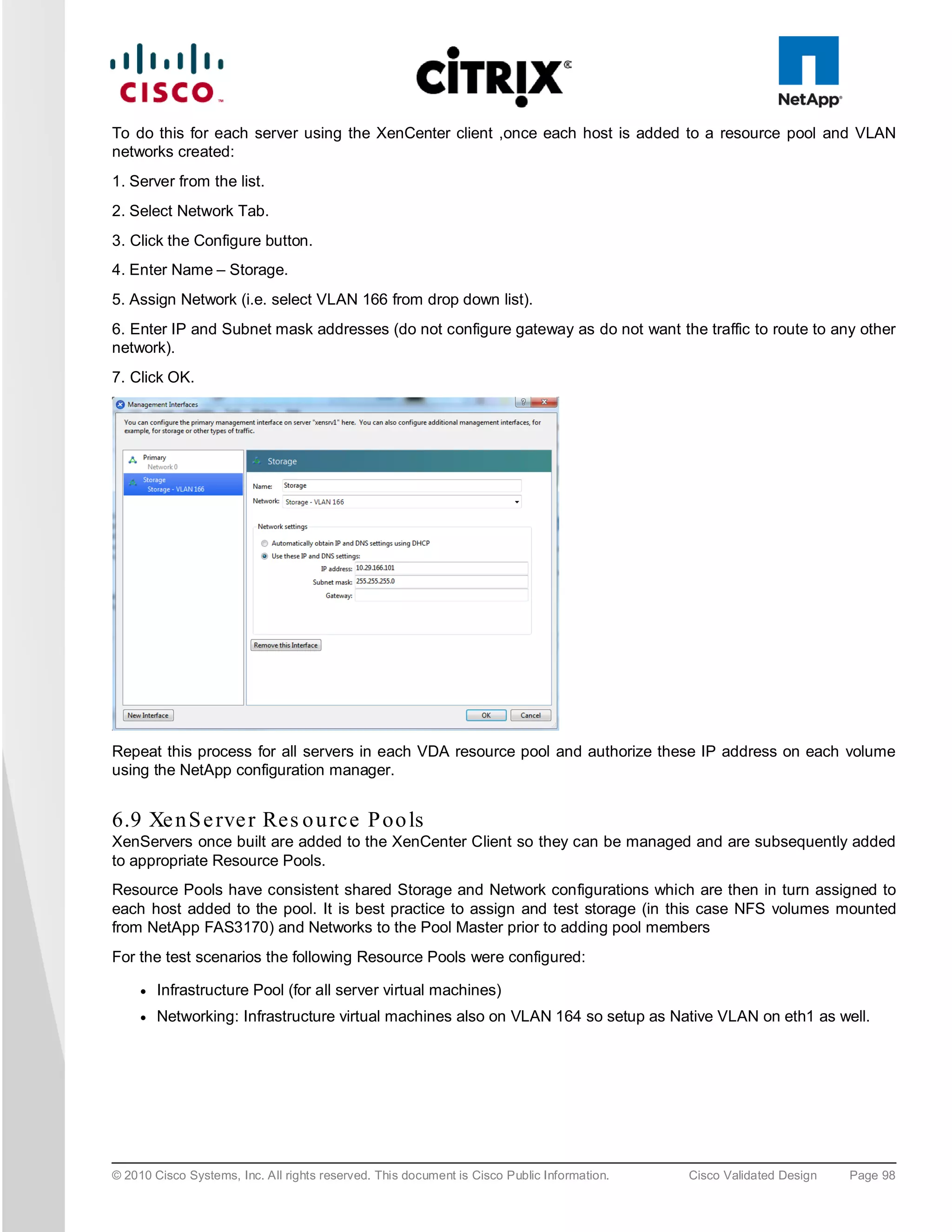
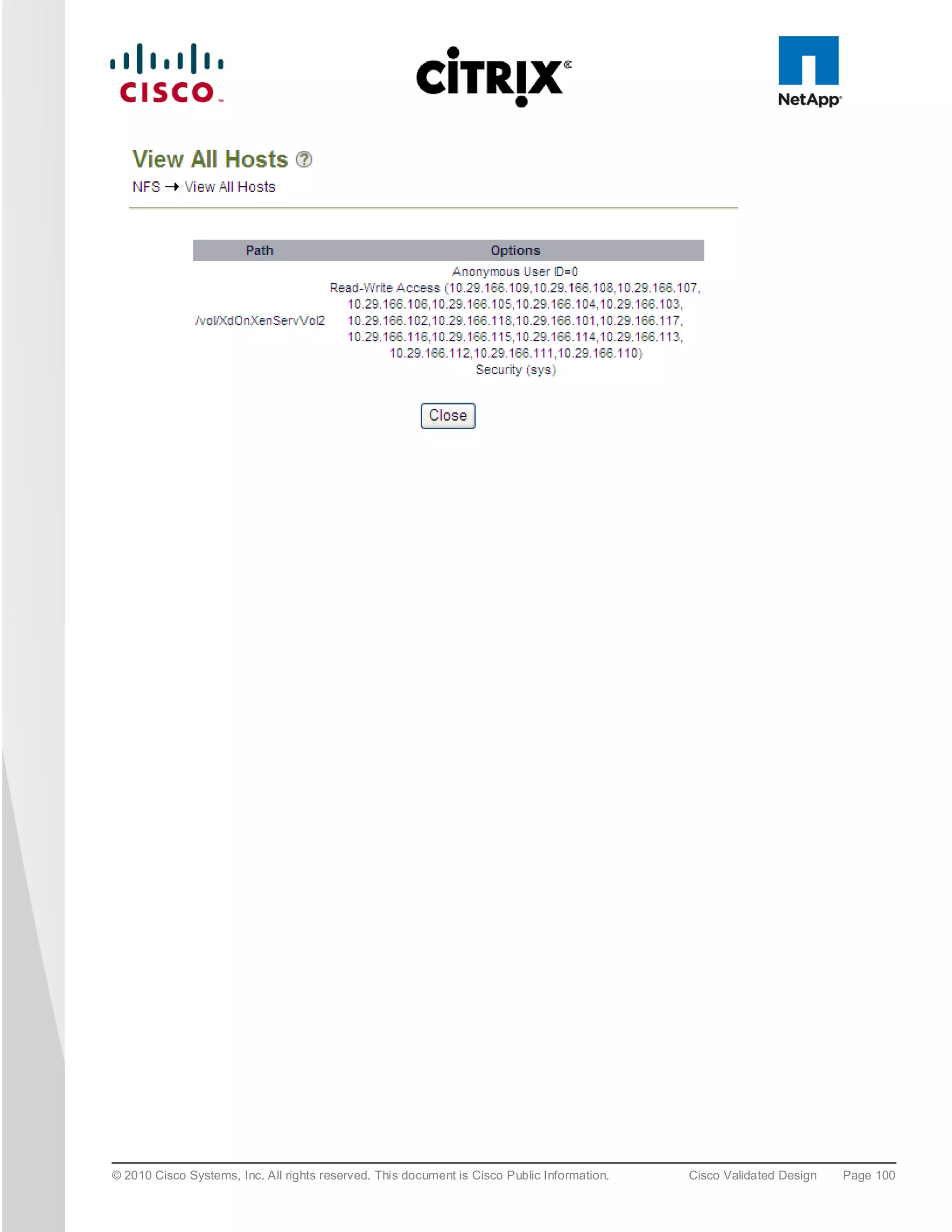
6.8.1 Xe n S e rve r Ne two rkin g
Storage traffic can be separated from Management traffic by configuring an additional Management Interface on
each XenServer (since the VDA servers have 4 physical NICs this approach was used), with an IP address
assigned on the Storage network VLAN (166). On the NetApp controllers, only these IP addresses are given
permissions to access the relevant volume; which stops the storage traffic going over the default management
NIC and also helps ensure that storage traffic is not routed.
© 2010 Cisco Systems, Inc. All rights reserved. This document is Cisco Public Information. Cisco Validated Design Page 97](https://image.slidesharecdn.com/ucsxdxenserverntap-110704045224-phpapp01/75/Cisco-Virtualization-Experience-Infrastructure-97-2048.jpg)


![Vibe Coding vs. Spec-Driven Development [Free Meetup]](https://cdn.slidesharecdn.com/ss_thumbnails/vibecodingvsspecdrivendevelopment-251209105622-43f455e7-thumbnail.jpg?width=640&height=640&fit=bounds)


