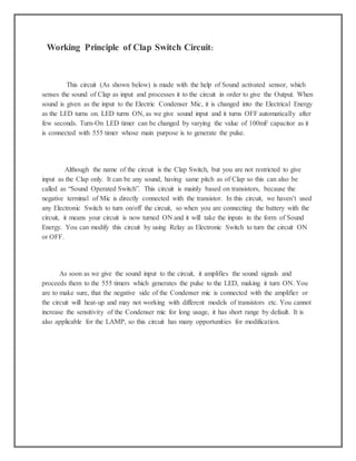
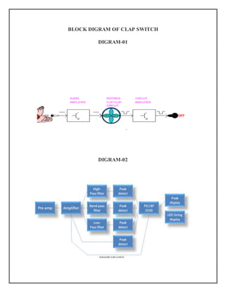
Clap Switch
ABSTRACT:
Introduction:
Clap Switch is a basic Electronics mini-project, made with the help of the basic
components. Clap Switch has the ability to turn ON/OFF any electrical component or circuit
by the clap sound.
It is known as Clap Switch, because the condenser mic which will be used in this Project
will have an ability to take the sound having same pitch as the Clap sound as the input. Although
it doesn’t mean that the sound will have to be of Clap sound, it can be any sound having the
same high pitch as of Clap. We can also say that it converts the Sound energy into the Electrical
Energy, because we are giving an input to the circuit as a sound whereas the Circuit gives us the
output as a LED glow (Electrical Energy).
This is a project on CLAP SWITCH which can switch on/off any electrical circuit by the sound of the
clap. The clap-operated circuit is a circuit which operates by clapping from a remote point. When a person
claps one, the first output of the circuit is turned on. If another one is clapped, the second output is switched
on and then another one will cause to energize the third output.
The basic idea of clap switch is that the electric microphone picks up the sound of your claps, coughs,
and the sound of that book knocked off the table. It produces a small electrical signal which is amplified by
the succeeding transistor stage. Two transistors cross connected as a bistable multivibrator change state at
each signal. One of these transistors drives a heavier transistor which controls a lamp. Basically, this is a
Sound operated switch.
CIRCUIT DIAGRAM:
Required Components
As already mentioned, this project is basic Electronics mini-project, so this project is made of the
basic components. Following is the list of the components required to make the Clap Switch.
1. 1K, 4.7K, 47K, 330 and 470 ohm resistors
2. 10µF and 2 100nF capacitors
3. Electric Condenser mic
4. Two BC547 transistors
5. LED/LASER
6. 12V Battery
Working Principle of Clap Switch Circuit:
This circuit (As shown below) is made with the help of Sound activated sensor, which
senses the sound of Clap as input and processes it to the circuit in order to give the Output. When
sound is given as the input to the Electric Condenser Mic, it is changed into the Electrical Energy
as the LED turns on. LED turns ON, as we give sound input and it turns OFF automatically after
few seconds. Turn-On LED timer can be changed by varying the value of 100mF capacitor as it
is connected with 555 timer whose main purpose is to generate the pulse.
Although the name of the circuit is the Clap Switch, but you are not restricted to give
input as the Clap only. It can be any sound, having same pitch as of Clap so this can also be
called as “Sound Operated Switch”. This circuit is mainly based on transistors, because the
negative terminal of Mic is directly connected with the transistor. In this circuit, we haven’t used
any Electronic Switch to turn on/off the circuit, so when you are connecting the battery with the
circuit, it means your circuit is now turned ON and it will take the inputs in the form of Sound
Energy. You can modify this circuit by using Relay as Electronic Switch to turn the circuit ON
or OFF.
As soon as we give the sound input to the circuit, it amplifies the sound signals and
proceeds them to the 555 timers which generates the pulse to the LED, making it turn ON. You
are to make sure, that the negative side of the Condenser mic is connected with the amplifier or
the circuit will heat-up and may not working with different models of transistors etc. You cannot
increase the sensitivity of the Condenser mic for long usage, it has short range by default. It is
also applicable for the LAMP, so this circuit has many opportunities for modification.
Advantages & Disadvantages:
1. It can used to turn ON and OFF the LED or LAMP simply, by clapping your hands.
2. We can also remove LEDs and place a FAN or any other electric component on the output in
order to get desired result.
3. The Condenser Mic used in this circuit has the short range as a default, which cannot be
varied.
Applications:
Clap Switch is not restricted to turn the LEDs ON and OFF, but it can be used in any electric
appliances such as Tube Light, Fan, Radio or any other basic circuit which you want to turn ON
by a Sound.
BLOCK DIGRAM OF CLAP SWITCH
DIGRAM-01
DIGRAM-02
Clap

Clap

  • 1.
    Clap Switch ABSTRACT: Introduction: Clap Switchis a basic Electronics mini-project, made with the help of the basic components. Clap Switch has the ability to turn ON/OFF any electrical component or circuit by the clap sound. It is known as Clap Switch, because the condenser mic which will be used in this Project will have an ability to take the sound having same pitch as the Clap sound as the input. Although it doesn’t mean that the sound will have to be of Clap sound, it can be any sound having the same high pitch as of Clap. We can also say that it converts the Sound energy into the Electrical Energy, because we are giving an input to the circuit as a sound whereas the Circuit gives us the output as a LED glow (Electrical Energy). This is a project on CLAP SWITCH which can switch on/off any electrical circuit by the sound of the clap. The clap-operated circuit is a circuit which operates by clapping from a remote point. When a person claps one, the first output of the circuit is turned on. If another one is clapped, the second output is switched on and then another one will cause to energize the third output. The basic idea of clap switch is that the electric microphone picks up the sound of your claps, coughs, and the sound of that book knocked off the table. It produces a small electrical signal which is amplified by the succeeding transistor stage. Two transistors cross connected as a bistable multivibrator change state at each signal. One of these transistors drives a heavier transistor which controls a lamp. Basically, this is a Sound operated switch.
  • 2.
    CIRCUIT DIAGRAM: Required Components Asalready mentioned, this project is basic Electronics mini-project, so this project is made of the basic components. Following is the list of the components required to make the Clap Switch. 1. 1K, 4.7K, 47K, 330 and 470 ohm resistors 2. 10µF and 2 100nF capacitors 3. Electric Condenser mic 4. Two BC547 transistors 5. LED/LASER 6. 12V Battery
  • 3.
    Working Principle ofClap Switch Circuit: This circuit (As shown below) is made with the help of Sound activated sensor, which senses the sound of Clap as input and processes it to the circuit in order to give the Output. When sound is given as the input to the Electric Condenser Mic, it is changed into the Electrical Energy as the LED turns on. LED turns ON, as we give sound input and it turns OFF automatically after few seconds. Turn-On LED timer can be changed by varying the value of 100mF capacitor as it is connected with 555 timer whose main purpose is to generate the pulse. Although the name of the circuit is the Clap Switch, but you are not restricted to give input as the Clap only. It can be any sound, having same pitch as of Clap so this can also be called as “Sound Operated Switch”. This circuit is mainly based on transistors, because the negative terminal of Mic is directly connected with the transistor. In this circuit, we haven’t used any Electronic Switch to turn on/off the circuit, so when you are connecting the battery with the circuit, it means your circuit is now turned ON and it will take the inputs in the form of Sound Energy. You can modify this circuit by using Relay as Electronic Switch to turn the circuit ON or OFF. As soon as we give the sound input to the circuit, it amplifies the sound signals and proceeds them to the 555 timers which generates the pulse to the LED, making it turn ON. You are to make sure, that the negative side of the Condenser mic is connected with the amplifier or the circuit will heat-up and may not working with different models of transistors etc. You cannot increase the sensitivity of the Condenser mic for long usage, it has short range by default. It is also applicable for the LAMP, so this circuit has many opportunities for modification.
  • 4.
    Advantages & Disadvantages: 1.It can used to turn ON and OFF the LED or LAMP simply, by clapping your hands. 2. We can also remove LEDs and place a FAN or any other electric component on the output in order to get desired result. 3. The Condenser Mic used in this circuit has the short range as a default, which cannot be varied. Applications: Clap Switch is not restricted to turn the LEDs ON and OFF, but it can be used in any electric appliances such as Tube Light, Fan, Radio or any other basic circuit which you want to turn ON by a Sound.
  • 5.
    BLOCK DIGRAM OFCLAP SWITCH DIGRAM-01 DIGRAM-02