This document provides guidance for troubleshooting issues that may occur when deploying a storage area network (SAN) using Cisco MDS 9000 Family switches. It covers basic troubleshooting methodology and tools, troubleshooting issues for a single switch or between switches, fabric-level issues, and IP storage troubleshooting. The document is organized into chapters covering an overview, switch hardware and booting problems, switch and interswitch connectivity, fabric-level issues, IP storage issues, troubleshooting the fabric, and Fabric Manager issues.


![Se n d c o m m e n t s t o m d s f e e d b a ck -d o c @ c i sc o . c o m .
x
Cisco MDS 9000 Family Troubleshooting Guide
OL-5183-02, Cisco MDS SAN-OS Release 1.3
Preface
Document Conventions
Document Conventions
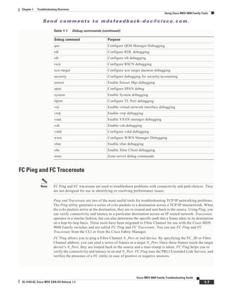
Command descriptions use these conventions:
Screen examples use these conventions:
This document uses the following conventions:
Note Means reader take note. Notes contain helpful suggestions or references to material not covered in the
manual.
Caution Means reader be careful. In this situation, you might do something that could result in equipment
damage or loss of data.
Related Documentation
For Fabric Manager and Device Manager field descriptions, refer to the Cisco MDS 9000 Family Fabric
Manager Online Help. For additional information, refer to the following documents:
• Regulatory Compliance and Safety Information for the Cisco MDS 9000 Family
• Cisco MDS 9100 Series Hardware Installation Guide
• Cisco MDS 9200 Series Hardware Installation Guide
• Cisco MDS 9500 Series Hardware Installation Guide
• Cisco MDS 9000 Family Configuration Guide
• Cisco MDS 9000 Family Command Reference
• Cisco MDS 9000 Family System Messages Guide
boldface font Commands and keywords are in boldface.
italic font Arguments for which you supply values are in italics.
[ ] Elements in square brackets are optional.
[ x | y | z ] Optional alternative keywords are grouped in brackets and separated by vertical
bars.
string A nonquoted set of characters. Do not use quotation marks around the string or
the string will include the quotation marks.
screen font Terminal sessions and information the switch displays are in screen font.
boldface screen font Information you must enter is in boldface screen font.
italic screen font Arguments for which you supply values are in italic screen font.
< > Nonprinting characters, such as passwords are in angle brackets.
[ ] Default responses to system prompts are in square brackets.
!, # An exclamation point (!) or a pound sign (#) at the beginning of a line of code
indicates a comment line.](https://image.slidesharecdn.com/tsgd-170311102023/85/Cisco-San-switch-troublehooting-Guide-10-320.jpg)


![Se n d c o m m e n t s t o m d s f e e d b a ck -d o c @ c i sc o . c o m .
1-5
Cisco MDS 9000 Family Troubleshooting Guide
OL-5183-02, Cisco MDS SAN-OS Release 1.3
Chapter 1 Troubleshooting Overview
Using Cisco MDS 9000 Family Tools
Command-Line-Interface (CLI)
The Cisco MDS 9000 Family CLI lets you configure and monitor a Cisco MDS 9000 Family switch
using a local console or remotely using a Telnet or SSH session. The CLI provides a command structure
similar to Cisco IOS®
software, with context-sensitive help, show commands, multi-user support, and
roles-based access control.
CLI Debug
The Cisco MDS 9000 Family of switches includes an extensive debugging feature set for actively
troubleshooting a storage network. Using the CLI, you can enable debugging modes for each switch
feature and view a real-time updated activity log of the control protocol exchanges. Each log entry is
time-stamped and listed in chronological order. Access to the debug feature can be limited through the
CLI roles mechanism and can be partitioned on a per-role basis. While debug commands show realtime
information, the show commands can be used to list historical information as well as realtime.
Note You can log debug messages to a special log file, which is more secure and easier to process than sending
the debug output to the console.
By using the '?' option, you can see the options that are available for any switch feature, such as FSPF.
A log entry is created for each entered command in addition to the actual debug output. The debug output
shows a time-stamped account of activity occurring between the local switch and other adjacent
switches.
You can use the debug facility to keep track of events, internal messages and protocol errors. However,
you should be careful with using the debug utility in a production environment, because some options
may prevent access to the switch by generating too many messages to the console or if very
CPU-intensive may seriously affect switch performance.
Note It is a good idea to open a second Telnet or SSH session before entering any debug commands. That way,
if the debug output comes too fast to stop it in the output window, you can use the second session to enter
the undebug all command to stop the debug message output.
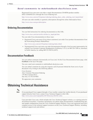
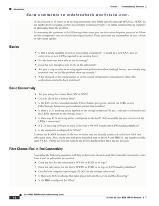
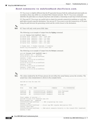
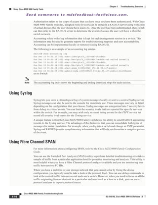
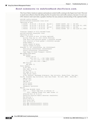
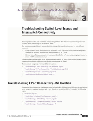
The following is an example of the output from the debug flogi event command
switch# debug flogi event interface fc1/1
Dec 10 23:40:26 flogi: current state [FLOGI_ST_FLOGI_RECEIVED]
Dec 10 23:40:26 flogi: current event [FLOGI_EV_VALID_FLOGI]
Dec 10 23:40:26 flogi: next state [FLOGI_ST_GET_FCID]
Dec 10 23:40:26 flogi: fu_fsm_execute: ([1]21:00:00:e0:8b:08:96:22)
Dec 10 23:40:26 flogi: current state [FLOGI_ST_GET_FCID]
Dec 10 23:40:26 flogi: current event [FLOGI_EV_VALID_FCID]
Dec 10 23:40:26 flogi: next state [FLOGI_ST_PERFORM_CONFIG]
Dec 10 23:40:26 flogi: fu_fsm_execute: ([1]21:00:00:e0:8b:08:96:22)
Dec 10 23:40:26 flogi: current state [FLOGI_ST_PERFORM_CONFIG]
Dec 10 23:40:26 flogi: current event [FLOGI_EV_CONFIG_DONE_PENDING]
Dec 10 23:40:26 flogi: next state [FLOGI_ST_PERFORM_CONFIG]
Dec 10 23:40:26 flogi: fu_fsm_execute: ([1]21:00:00:e0:8b:08:96:22)
Dec 10 23:40:26 flogi: current state [FLOGI_ST_PERFORM_CONFIG]
Dec 10 23:40:26 flogi: current event [FLOGI_EV_RIB_RESPOSE]
Dec 10 23:40:26 flogi: next state [FLOGI_ST_PERFORM_CONFIG]
Dec 10 23:40:26 flogi: fu_fsm_execute: ([1]21:00:00:e0:8b:08:96:22)
Dec 10 23:40:26 flogi: current state [FLOGI_ST_PERFORM_CONFIG]](https://image.slidesharecdn.com/tsgd-170311102023/85/Cisco-San-switch-troublehooting-Guide-21-320.jpg)
![Se n d c o m m e n t s t o m d s f e e d b a ck -d o c @ c i sc o . c o m .
1-6
Cisco MDS 9000 Family Troubleshooting Guide
OL-5183-02, Cisco MDS SAN-OS Release 1.3
Chapter 1 Troubleshooting Overview
Using Cisco MDS 9000 Family Tools
Dec 10 23:40:26 flogi: current event [FLOGI_EV_NAME_SERVER_REG_RESPONSE]
Dec 10 23:40:26 flogi: next state [FLOGI_ST_PERFORM_CONFIG]
Dec 10 23:40:26 flogi: fu_fsm_execute: ([1]21:00:00:e0:8b:08:96:22)
Dec 10 23:40:26 flogi: current state [FLOGI_ST_PERFORM_CONFIG]
Dec 10 23:40:26 flogi: current event [FLOGI_EV_ACL_CFG_RESPONSE]
Dec 10 23:40:26 flogi: next state [FLOGI_ST_PERFORM_CONFIG]
Dec 10 23:40:26 flogi: current state [FLOGI_ST_PERFORM_CONFIG]
Dec 10 23:40:26 flogi: current event [FLOGI_EV_ZS_CFG_RESPONSE]
Dec 10 23:40:26 flogi: next state [FLOGI_ST_PERFORM_CONFIG]
Dec 10 23:40:26 flogi: fu_fsm_execute_all: done processing event FLOGI_EV_ZS_CFG_RESPONSE
Dec 10 23:40:26 flogi: current state [FLOGI_ST_PERFORM_CONFIG]
Dec 10 23:40:26 flogi: current event [FLOGI_EV_LCP_RESPONSE]
Dec 10 23:40:26 flogi: next state [FLOGI_ST_PERFORM_CONFIG]
Dec 10 23:40:26 flogi: fu_fsm_execute: ([1]21:00:00:e0:8b:08:96:22)
Dec 10 23:40:26 flogi: current state [FLOGI_ST_PERFORM_CONFIG]
Dec 10 23:40:26 flogi: current event [FLOGI_EV_CONFIG_DONE_COMPLETE]
Dec 10 23:40:26 flogi: next state [FLOGI_ST_FLOGI_DONE]
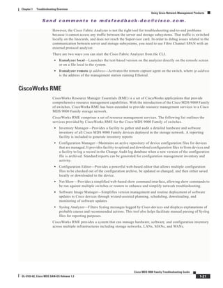
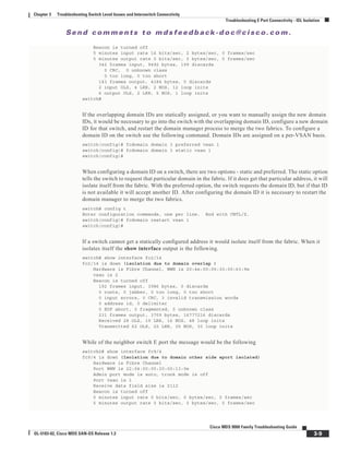
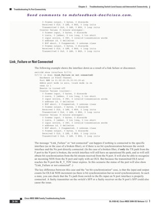
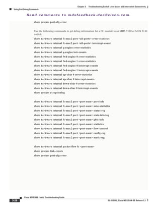
The following is a summary of the available debug commands:
Table 1-1 Debug commands
Debug command Purpose
acl Enable acl debugging
all Enable all debugging
ascii-cfg Configure ascii-cfg debugging
bootvar Enable bootvar debugging
callhome Enable debugging for Callhome
fc2 Configure FC2 debugging
fcc Enable FCC debugging
fcdomain Enable fcdomain debugging
fcfwd Enable fcfwd debugging
fcns Debug name server
fcs Configure Fabric Configuration Server Debugging
flogi Configure flogi debug
fspf Configure FSPF debugging
hardware Debug hardware, kernel loadable module parameters
ipconf Enable IP configuration debugging
ipfc Enable IPFC debugging
klm Debug kernel loadable module parameters
logfile Direct debug output to logfile
mcast Enable mcast debugging
mip Debug multiple IP kernel driver
module Configure LC Manager debugging
ntp Debug NTP module
platform Configure Platform Manager debugging
port Configure port debugging
port-channel Enable port-channel debug](https://image.slidesharecdn.com/tsgd-170311102023/85/Cisco-San-switch-troublehooting-Guide-22-320.jpg)

![Se n d c o m m e n t s t o m d s f e e d b a ck -d o c @ c i sc o . c o m .
2-5
Cisco MDS 9000 Family Troubleshooting Guide
OL-5183-02, Cisco MDS SAN-OS Release 1.3
Chapter 2 Troubleshooting Switch System Issues
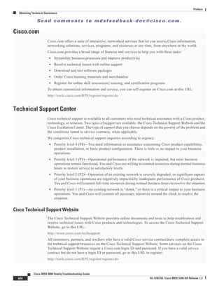
Troubleshooting System Restarts
Service: ips
Description: IPS Manager
Started at Tue Jan 8 17:07:42 1980 (757583 us)
Stopped at Thu Jan 10 06:16:45 1980 (83451 us)
Uptime: 1 days 13 hours 9 minutes 9 seconds
Start type: SRV_OPTION_RESTART_STATELESS (23)
Death reason: SYSMGR_DEATH_REASON_FAILURE_SIGNAL (2)
Exit code: signal 6 (core dumped)
CWD: /var/sysmgr/work
Virtual Memory:
CODE 08048000 - 080FB060
DATA 080FC060 - 080FCBA8
BRK 081795C0 - 081EC000
STACK 7FFFFCF0
TOTAL 20952 KB
Register Set:
EBX 000005C1 ECX 00000006 EDX 2AD721E0
ESI 2AD701A8 EDI 08109308 EBP 7FFFF2EC
EAX 00000000 XDS 0000002B XES 0000002B
EAX 00000025 (orig) EIP 2AC8CC71 XCS 00000023
EFL 00000207 ESP 7FFFF2C0 XSS 0000002B
Stack: 2608 bytes. ESP 7FFFF2C0, TOP 7FFFFCF0
0x7FFFF2C0: 2AC8C944 000005C1 00000006 2AC735E2 D..*.........5.*
0x7FFFF2D0: 2AC8C92C 2AD721E0 2AAB76F0 00000000 ,..*.!.*.v.*....
0x7FFFF2E0: 7FFFF320 2AC8C920 2AC513F8 7FFFF42C ... ..*...*,...
0x7FFFF2F0: 2AC8E0BB 00000006 7FFFF320 00000000 ...*.... .......
0x7FFFF300: 2AC8DFF8 2AD721E0 08109308 2AC65AFC ...*.!.*.....Z.*
0x7FFFF310: 00000393 2AC6A49C 2AC621CC 2AC513F8 .......*.!.*...*
0x7FFFF320: 00000020 00000000 00000000 00000000 ...............
0x7FFFF330: 00000000 00000000 00000000 00000000 ................
0x7FFFF340: 00000000 00000000 00000000 00000000 ................
0x7FFFF350: 00000000 00000000 00000000 00000000 ................
0x7FFFF360: 00000000 00000000 00000000 00000000 ................
0x7FFFF370: 00000000 00000000 00000000 00000000 ................
0x7FFFF380: 00000000 00000000 00000000 00000000 ................
0x7FFFF390: 00000000 00000000 00000000 00000000 ................
0x7FFFF3A0: 00000002 7FFFF3F4 2AAB752D 2AC5154C .
... output abbreviated ...
Stack: 128 bytes. ESP 7FFFF830, TOP 7FFFFCD0
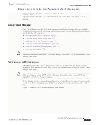
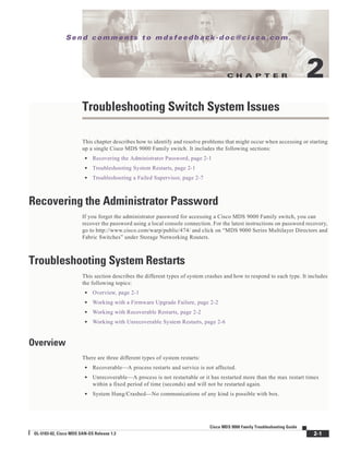
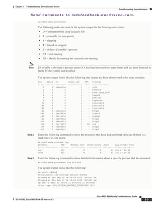
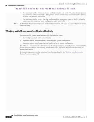
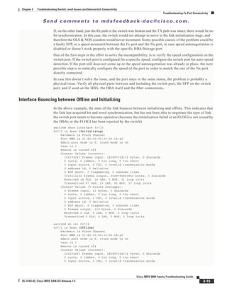
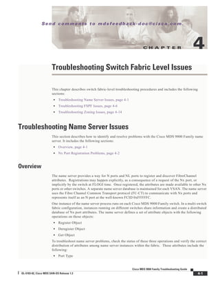
Step 7 Enter the following command configure the switch to use TFTP to send the core dump to a TFTP server.
switch(config)# sys cores tftp:[//servername][/path]
This command causes the switch to enable the automatic copy of core files to a TFTP server. For
example, the following command sends the core files to the TFTP server with the IP address 10.1.1.1.
switch(config)# system cores tftp://10.1.1.1/cores
The following conditions apply:
• The core files are copied every 4 minutes. This time is not configurable.
• The copy of a specific core file can be manually triggered, using the command
copy core//module#/pid# tftp//tftp_ip_address/file_name](https://image.slidesharecdn.com/tsgd-170311102023/85/Cisco-San-switch-troublehooting-Guide-43-320.jpg)

![Se n d c o m m e n t s t o m d s f e e d b a ck -d o c @ c i sc o . c o m .
3-2
Cisco MDS 9000 Family Troubleshooting Guide
OL-5183-02, Cisco MDS SAN-OS Release 1.3
Chapter 3 Troubleshooting Switch Level Issues and Interswitch Connectivity
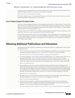
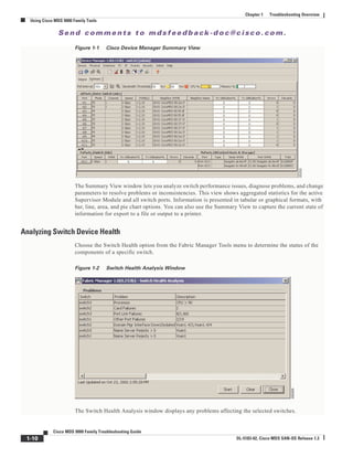
Troubleshooting E Port Connectivity - ISL Isolation
Overview
On an E port, only one VSAN can be passed and possibly be isolated. However, in a trunking E port
(TE), multiple VSANs can become isolated while others are passing traffic. The same troubleshooting
approach applies in both cases, except that on a trunking E port the troubleshooting may need to be done
on a per-VSAN basis and/or on multiple VSANs.
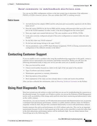
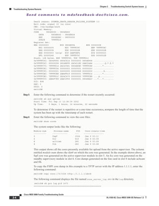
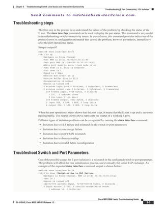
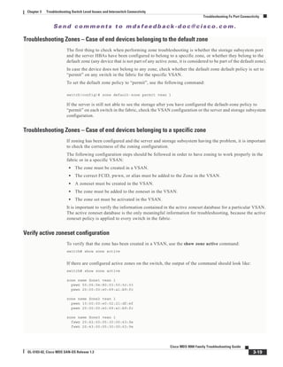
Step 1) Verify that each VSAN is able to see the other switches within the same VSAN.
To verify that each switch is able to see the other switches, issue the following command at the exec
prompt. This command is VSAN-specific. If a specific VSAN is omitted from the command, it will list
the output for all VSANs.
switch# show fcdomain domain-list vsan 1
The output of the command lists set of domain IDs and associated WWNs for each switch within a
VSAN. This list provides the WWN of the switches owning each domain ID and the information about
the principality of those switches in the fabric or VSAN they belong to.
Sample output #1 (obtained in a fabric with just 2 switches in VSAN 1)
switch# sh fcdomain domain-list vsan 1
Number of domains: 2
Domain ID WWN
--------- --------------------------------
0x4a(74) 20:01:00:05:30:00:13:9f [Local]
0x4b(75) 20:01:00:05:30:00:13:9e [Principal]
------- --------------------------------------
This is an output of VSAN 1 in which 2 switches are seen. This indicates that the switch where the
command has been issued has built its adjacency on VSAN 1 with the other switch in the same VSAN.
Sample output #2
switch# sh fcdomain domain-list vsan 1
Number of domains: 1
Domain ID WWN
--------- -----------------------
0x4a(74) 20:01:00:05:30:00:13:9f [Local] [Principal]
--------- -----------------------
In this output only one switch is seen. This indicates that the switch where the command has been issued
has not established adjacency with the neighboring switch in VSAN 1.
Possible Causes for the problem
In the previous output one domain ID is missing. The reason of this can be found in the erroneous
configuration of several parameters between adjacent switches.
In case of E port/VSAN isolation the following parameters and configurations should be checked in each
switch:
• Zoning configuration
• VSAN configuration
• Domain ID parameters
• Fabric Parameters & Timers](https://image.slidesharecdn.com/tsgd-170311102023/85/Cisco-San-switch-troublehooting-Guide-48-320.jpg)
![Se n d c o m m e n t s t o m d s f e e d b a ck -d o c @ c i sc o . c o m .
3-4
Cisco MDS 9000 Family Troubleshooting Guide
OL-5183-02, Cisco MDS SAN-OS Release 1.3
Chapter 3 Troubleshooting Switch Level Issues and Interswitch Connectivity
Troubleshooting E Port Connectivity - ISL Isolation
Received 0 runts, 0 jabber, 0 too long, 0 too short
0 EOF abort, 0 fragmented, 0 unknown class
100 OLS, 67 LRR, 37 NOS, 0 loop inits
133283352 packets output, 1332969530 bytes
Transmitted 198 OLS, 50 LRR, 0 NOS, 10 loop inits
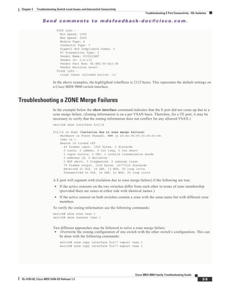
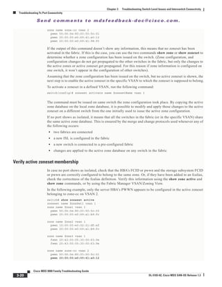
In this example the interface is indicating a link isolation caused by an ELP failure on an E port. The
ELP is a frame sent between two switches to negotiate fabric parameters. If you get this failure, verify
the fabric parameters are the same for both switches.
Since fabric parameters are configured on a per switch basis, however, they are required to be the same
for all switches within a fabric.
If the interface indicates an ELP failure verify the following parameters match using the show fctimer
command:
• ED_TOV Timer
• RA_TOV Timer
• FS_TOV timer
An example of the show fctimer command where all default value are in use, is shown below
switch# show fctimer
F_S_TOV : 5000 milliseconds
D_S_TOV : 15000 milliseconds
E_D_TOV : 2000 milliseconds
R_A_TOV : 10000 milliseconds
Another parameter to check, is the Rcxbuffer size on the interface. This value should match on both the
ends of a ISL. To verify the value of the Rcxbuffer size, use the following command:
switch# show port internal info interface fc2/1
fc2/1 - if_index: 1080000
Admin Config - state(up), mode(Auto), speed(auto), trunk(no trunk)
beacon(off), snmp trap(on), tem(false)
bb_credit(default), rxbufsize(2112), encap(default)
description()
Operational Info - state(down), mode(ALL), speed(auto), trunk(no trunk)
state reason(Link failure or not-connected)
phy port enable (1), phy layer (FC)
participating(1), port_vsan(1), null_vsan(0), fcid(0x000000)
current state [PI_FSM_ST_LINK_INIT]
port_init_eval_flag(0x00000001), cfg wait for none
Mts node id 0x202
cnt_link_failure(0), cnt_link_success(0), cnt_port_up(0)
cnt_cfg_wait_timeout(0), cnt_port_cfg_failure(0), cnt_init_retry(0)
Port Capabilities -
Modes: E,TE,F,FL,TL,SD
Min Speed: 1000
Max Speed: 2000
Max Tx Bytes: 2112
Max Rx Bytes: 2112
Max Tx Buffer Credit: 255
Max Rx Buffer Credit: 16
Max Private Devices: 63
Max Sourcable Pkt Size: 2112
Hw Capabilities: 0xb
Connector Type: 0x0](https://image.slidesharecdn.com/tsgd-170311102023/85/Cisco-San-switch-troublehooting-Guide-50-320.jpg)
![Se n d c o m m e n t s t o m d s f e e d b a ck -d o c @ c i sc o . c o m .
3-8
Cisco MDS 9000 Family Troubleshooting Guide
OL-5183-02, Cisco MDS SAN-OS Release 1.3
Chapter 3 Troubleshooting Switch Level Issues and Interswitch Connectivity
Troubleshooting E Port Connectivity - ISL Isolation
switch# sh fcdomain domain-list vsan 1
Number of domains: 2
Domain ID WWN
--------- -----------------------
0x4a(74) 20:01:00:05:30:00:13:9f [Local]
0x4b(75) 20:01:00:05:30:00:13:9e [Principal]
------- -----------------------
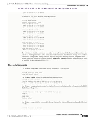
The output shown is representative of a simple two switches fabric.
If a domain is currently isolated due to domain overlap, and you later enable the auto-reconfigure option
on both switches, the fabric continues to be isolated. However, if you enable the auto-reconfigure option
on both switches before connecting the fabric, a disruptive reconfiguration (RCF) occurs. The RCF
functionality would automatically force a new principal switch selection and cause new domain ID to be
assigned to the different switches. A disruptive reconfiguration may affect data traffic.
To enable the auto-reconfigure option on a particular VSAN use the following command:
switch(config)# fcdomain auto-reconfigure vsan 10
There are different ways of resolving this issue. One possible solution is to cause an RCF in the fabric
with a disruptive restart of the domain manager on the switch. The RCF functionality will cause all
switches in both fabrics to empty their domain ID list and select a new principal switch. The overlapping
domain ID would be assigned to which ever switch requests it first from the newly selected principal
switch.
The second switch to request that same domain ID would be assigned a new domain ID. This will only
work if the overlapping domain IDs are not statically defined on the switches. If the domain ID is
statically defined on the switch, then the switch does not accept any other domain ID than the one that
is configured. If its request for the configured domain ID is not granted, it isolates itself from the fabric.
The RCF functionality is disruptive and can cause end nodes to be assigned new domain IDs. By default,
Cisco MDS 9000 Family switches accept disruptive restarts. You can configure the switch in order to
reject incoming RCFs on a per-VSAN and port level basis (enabling the rcf-reject option).
In case the rcf-reject option is on, in order to have the RCF propagated to the switches in the fabric,
must have the RCF reject property disabled. To turn this option off use the following command:
switch(config-if)# no fcdomain rcf-reject vsan 1
At this point a disruptive restart should be triggered, by using the following command:
switch# config t
Enter configuration commands, one per line. End with CNTL/Z.
switch(config)# fcdomain restart disruptive vsan 1
switch(config)#
When you do a disruptive restart on your switch and the switch on the other side does not have disruptive
restart enabled the error on the E port would be the following
switch# show interface fc2/5
fc2/5 is down (isolation due to invalid fabric reconfiguration)
Hardware is Fibre Channel
Port WWN is 20:45:00:05:30:00:18:a2
Admin port mode is auto, trunk mode is on
Port vsan is 1
Receive data field size is 2112](https://image.slidesharecdn.com/tsgd-170311102023/85/Cisco-San-switch-troublehooting-Guide-54-320.jpg)
![Se n d c o m m e n t s t o m d s f e e d b a ck -d o c @ c i sc o . c o m .
3-12
Cisco MDS 9000 Family Troubleshooting Guide
OL-5183-02, Cisco MDS SAN-OS Release 1.3
Chapter 3 Troubleshooting Switch Level Issues and Interswitch Connectivity
Troubleshooting TE Port Connectivity - VSAN Isolation
beacon(off), snmp trap(on), tem(false)
rx bb_credit(default), rx bb_credit multiplier(default)
rxbufsize(2112), encap(default), user_cfg_flag(0x3)
description()
Operational Info - state(trunking), mode(TE), speed(2 Gbps), trunk(on)
state reason(None)
phy port enable (1), phy layer (FC)
participating(1), port_vsan(7), fcid(0x000000)
rx bb_credit multiplier(0), rx bb_credit(12)
current state [PI_FSM_ST_TEPORT_INIT_TRUNKING_ENABLED]
port_init_eval_flag(0x00000001), cfg wait for none
Mts node id 0x202
eport_init_flag(0x00000386), elp_chk_flag(0x0000000A)
elp_rcvd_fc2_handle(0x00000000), elp_sent_fc2_handle(0x0800864E)
esc_chk_flag(0x0000002A), esc_fc2_handle(0x0801864F)
elp_flags(0x0000), classes_supported(F,2,3), tx bb_credit(255)
cnt_link_failure(1), cnt_link_success(5), cnt_port_up(0)
cnt_cfg_wait_timeout(0), cnt_port_cfg_failure(0), cnt_init_retry(0)
oper trunk mode(on)
Port Capabilities -
Modes: E,TE,F,FL,TL,SD
Min Speed: 1000
Max Speed: 2000
Max Sourcable Pkt Size: 2112
Max Tx Bytes: 2112
Max Rx Bytes: 2112
Max Tx Buffer Credit: 255
Max Rx Buffer Credit: 12
Max Rx Buffer Credit (ISL): 12
Default Rx Buffer Credit: 12
Default Rx Buffer Credit(ISL): 12
Default Rx Buffer Credit Multiplier: 0
Rx Buffer Credit change not allowed
Max Private Devices: 63
Hw Capabilities: 0xb
Connector Type: 0x0
FCOT info -
Min Speed: 1000
Max Speed: 2000
Module Type: 8
Connector Type: 7
Gigabit Eth Compliance Codes: 0
FC Transmitter Type: 3
Vendor Name: IBM
Vendor ID: 8:0:90
Vendor Part Num: IBM42P21SNY
Vendor Revision Level: AA20
Trunk Info -
trunk vsans (allowed active) (1,7-8)
trunk vsans (up) (7)
trunk vsans (isolated) (1,8)
TE port per vsan information
fc2/29, Vsan 1 - state(down), state reason(Isolation due to domain other side eport
isolated), fcid(0x000000)
port init flag(0x10000), current state [TE_FSM_ST_ISOLATED_DM_ZS]
fc2/29, Vsan 7 - state(up), state reason(None), fcid(0x690202)
port init flag(0x38000), current state [TE_FSM_ST_E_PORT_UP]
fc2/29, Vsan 8 - state(down), state reason(Isolation due to vsan not configure
d on peer), fcid(0x000000)
port init flag(0x0), current state [TE_FSM_ST_ISOLATED_VSAN_MISMATCH]
switch#](https://image.slidesharecdn.com/tsgd-170311102023/85/Cisco-San-switch-troublehooting-Guide-58-320.jpg)

![Se n d c o m m e n t s t o m d s f e e d b a ck -d o c @ c i sc o . c o m .
3-18
Cisco MDS 9000 Family Troubleshooting Guide
OL-5183-02, Cisco MDS SAN-OS Release 1.3
Chapter 3 Troubleshooting Switch Level Issues and Interswitch Connectivity
Troubleshooting Fx Port Connectivity
description()
Operational Info - state(up), mode(F), speed(1 Gbps), trunk(off)
state reason(None)
phy port enable (1), phy layer (FC)
participating(1), port_vsan(1), null_vsan(0), fcid(0xef0300)
rx bb_credit multiplier(0), rx bb_credit(12)
current state [PI_FSM_ST_F_PORT_UP]
port_init_eval_flag(0x00003001), cfg wait for none
Mts node id 0x702
cnt_link_failure(54), cnt_link_success(53), cnt_port_up(4)
cnt_cfg_wait_timeout(0), cnt_port_cfg_failure(0), cnt_init_retry(0)
Port Capabilities -
Modes: E,TE,F,FL,TL,SD
Min Speed: 1000
Max Speed: 2000
Max Sourcable Pkt Size: 2112
Max Tx Bytes: 2112
Max Rx Bytes: 2112
Max Tx Buffer Credit: 255
Max Rx Buffer Credit: 12
Max Rx Buffer Credit (ISL): 12
Default Rx Buffer Credit: 12
Default Rx Buffer Credit(ISL): 12
Default Rx Buffer Credit Multiplier: 0
Rx Buffer Credit change not allowed
Max Private Devices: 63
Hw Capabilities: 0xb
Connector Type: 0x0
FCOT info -
Min Speed: 1000
Max Speed: 2000
Module Type: 8
Connector Type: 7
Gigabit Eth Compliance Codes: 0
FC Transmitter Type: 3
Vendor Name: CISCO-AGILENT
Vendor ID: 0:48:211
Vendor Part Num: QFBR-5796L
Vendor Revision Level:
Trunk Info -
trunk vsans (allowed active) (1)
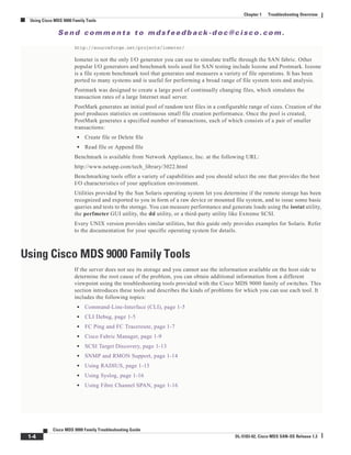
If the configuration of the switch port is configured as auto, and the point-to-point link still comes up as
an FL port, verify that the HBA is configured as an NL port also.
Some HBAs support only NL mode. Verify the HBA capabilities with the vendor.
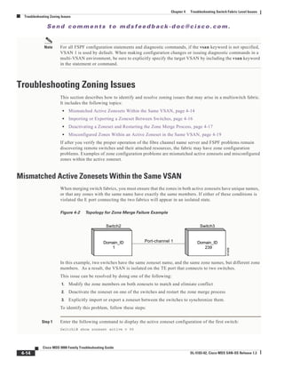
Interface UP and Connectivity Problems - Troubleshooting VSANs and Zones
If a server is not able to see a storage device, it may be because of a VSAN or zone misconfiguration.
Zone problems are more likely to happen than VSAN issues. This is because zone configuration and the
overall zone protocols are more complex than VSAN configuration, and the VSAN membership can be
verified using the CLI or the GUI. Therefore, checking the zone configuration is the first step to take
when the host is not able to access the storage, and the port are all up along the path between the server
HBA and the storage subsystem interface.](https://image.slidesharecdn.com/tsgd-170311102023/85/Cisco-San-switch-troublehooting-Guide-64-320.jpg)
![Se n d c o m m e n t s t o m d s f e e d b a ck -d o c @ c i sc o . c o m .
4-3
Cisco MDS 9000 Family Troubleshooting Guide
OL-5183-02, Cisco MDS SAN-OS Release 1.3
Chapter 4 Troubleshooting Switch Fabric Level Issues
Troubleshooting Name Server Issues
show flogi database vsan vsanid
The system output might look like this:
switch# show flogi database vsan 99
---------------------------------------------------------------------------
INTERFACE VSAN FCID PORT NAME NODE NAME
---------------------------------------------------------------------------
fc3/14 99 0x780200 21:00:00:e0:8b:07:a4:36 20:00:00:e0:8b:07:a4:36
If the device in question appears in this output, skip to Step 8. If the device does not appear in the output,
go to the next step.
Step 3 From interface mode, shut down the FC interface connected to the device in question.
config terminal
interface fcx/x
shutdown
Step 4 Enter the following command on the FC interface:
no shutdown
By shutting down the interface and bringing it back up, you can determine what happens when the
connected device tries to log in to the interface.
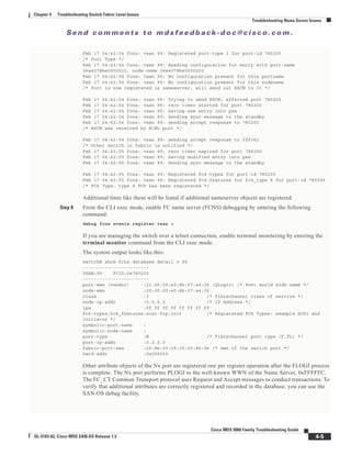
Step 5 Enter the following command to view the events that occurred on the interface after you enabled it again:
switch# show flogi internal event-history interface fc3/14
The system output looks like this:
>>>>FSM: <[99]21:00:00:e0:8b:07:a4:36> has 9 logged transitions<<<<<
/* This is the [VSAN] followed by the pwwn of the N/NL port */
1) FSM:<[99]21:00:00:e0:8b:07:a4:36> Transition at 321686 usecs after Sun Feb 1
04:18:15 1980
Previous state: [FLOGI_ST_FLOGI_RECEIVED]
Triggered event: [FLOGI_EV_VALID_FLOGI]
Next state: [FLOGI_ST_GET_FCID]
/* The hba has sent an FLOGI to the switch */
2) FSM:<[99]21:00:00:e0:8b:07:a4:36> Transition at 322974 usecs after Sun Feb 1
04:18:15 1980
Previous state: [FLOGI_ST_GET_FCID]
Triggered event: [FLOGI_EV_VALID_FCID]
Next state: [FLOGI_ST_PERFORM_CONFIG]
/* Port Manager Obtains a valid FC_ID from the Domain Mgr */
3) FSM:<[99]21:00:00:e0:8b:07:a4:36> Transition at 323731 usecs after Sun Feb 1
04:18:15 1980
Previous state: [FLOGI_ST_PERFORM_CONFIG]
Triggered event: [FLOGI_EV_CONFIG_DONE_PENDING]
Next state: [FLOGI_ST_PERFORM_CONFIG]
/* ACLs are programmed and FIB {VSAN, FC_ID, portindex} is set */
4) FSM:<[99]21:00:00:e0:8b:07:a4:36> Transition at 323948 usecs after Sun Feb 1
04:18:15 1980
Previous state: [FLOGI_ST_PERFORM_CONFIG]
Triggered event: [FLOGI_EV_LCP_RESPONSE]
Next state: [FLOGI_ST_PERFORM_CONFIG]
/* LineCard responds that it is done */](https://image.slidesharecdn.com/tsgd-170311102023/85/Cisco-San-switch-troublehooting-Guide-77-320.jpg)
![Se n d c o m m e n t s t o m d s f e e d b a ck -d o c @ c i sc o . c o m .
4-4
Cisco MDS 9000 Family Troubleshooting Guide
OL-5183-02, Cisco MDS SAN-OS Release 1.3
Chapter 4 Troubleshooting Switch Fabric Level Issues
Troubleshooting Name Server Issues
5) FSM:<[99]21:00:00:e0:8b:07:a4:36> Transition at 325962 usecs after Sun Feb 1
04:18:15 1980
Previous state: [FLOGI_ST_PERFORM_CONFIG]
Triggered event: [FLOGI_EV_NAME_SERVER_REG_RESPONSE]
Next state: [FLOGI_ST_PERFORM_CONFIG]
/* Program the NameServer with wwn and FCID */
6) FSM:<[99]21:00:00:e0:8b:07:a4:36> Transition at 330381 usecs after Sun Feb 1
04:18:15 1980
Previous state: [FLOGI_ST_PERFORM_CONFIG]
Triggered event: [FLOGI_EV_ZS_CFG_RESPONSE]
Next state: [FLOGI_ST_PERFORM_CONFIG]
/* Response from ZoneServer */
7) FSM:<[99]21:00:00:e0:8b:07:a4:36> Transition at 331187 usecs after Sun Feb 1
04:18:15 1980
Previous state: [FLOGI_ST_PERFORM_CONFIG]
Triggered event: [FLOGI_EV_RIB_RESPOSE]
Next state: [FLOGI_ST_PERFORM_CONFIG]
/* Response from RIB */
8) FSM:<[99]21:00:00:e0:8b:07:a4:36> Transition at 331768 usecs after Sun Feb 1
04:18:15 1980
Previous state: [FLOGI_ST_PERFORM_CONFIG]
Triggered event: [FLOGI_EV_ACL_CFG_RESPONSE]
Next state: [FLOGI_ST_PERFORM_CONFIG]
/* Response from RIB */
9) FSM:<[99]21:00:00:e0:8b:07:a4:36> Transition at 331772 usecs after Sun Feb 1
04:18:15 1980
Previous state: [FLOGI_ST_PERFORM_CONFIG]
Triggered event: [FLOGI_EV_CONFIG_DONE_COMPLETE]
Next state: [FLOGI_ST_FLOGI_DONE]
/* Programming done */
Curr state: [FLOGI_ST_FLOGI_DONE]
/* Flogi was successful */
The comments that follow each section of output explain the meaning of the output.
If the device logs in successfully, proceed to the next step. Otherwise, you may have a problem with the
device or its associated software.
Step 6 From interface mode, shut down the FC interface and issue a no shutdown after turning on the debug
described in the following steps.
Step 7 To watch the FLOGI process take place, enter the following command:
switch# debug fcns events register vsan 99
This command enables debug mode for nameserver registration. The system output looks like this:
switch# conf t
Enter configuration commands, one per line. End with CNTL/Z.
switch(config)# int fc3/14
switch(config-if)# no shut /* enable the port */
switch(config-if)# Feb 17 04:42:54 fcns: vsan 99: Created entry for port-id 27800
Feb 17 04:42:54 fcns: vsan 99: Got Entry for port-id 27800
Feb 17 04:42:54 fcns: vsan 99: Registered port-name 36a4078be0000021 for port-id 780200
Feb 17 04:42:54 fcns: vsan 99: Registered node-name 36a4078be0000020 for port-id 780200
/* The wwpn and FCID for the port, note that the bytes in the world wide name are reversed
*/
Feb 17 04:42:54 fcns: vsan 99: Registered cos 8 for port-id 780200
/* Class of Service */](https://image.slidesharecdn.com/tsgd-170311102023/85/Cisco-San-switch-troublehooting-Guide-78-320.jpg)
![Se n d c o m m e n t s t o m d s f e e d b a ck -d o c @ c i sc o . c o m .
4-15
Cisco MDS 9000 Family Troubleshooting Guide
OL-5183-02, Cisco MDS SAN-OS Release 1.3
Chapter 4 Troubleshooting Switch Fabric Level Issues
Troubleshooting Zoning Issues
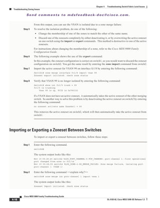
The system output looks like this:
Switch1# show zoneset active v 99
zoneset name ZoneSet1 vsan 99
zone name VZ1 vsan 99
* fcid 0x7800e2 [pwwn 22:00:00:20:37:04:ea:2b]
* fcid 0x7800d9 [pwwn 22:00:00:20:37:04:f8:a1]
Step 2 Enter the following command to display the active zoneset configuration of the second switch:
Switch2# show zoneset active v 99
The system output looks like this:
Switch2# show zoneset active v 99
zoneset name ZoneSet1 vsan 99
zone name VZ1 vsan 99
pwwn 22:00:00:20:37:04:f8:a1
pwwn 22:00:00:20:37:0e:65:44
Even though the zones have the same name, their respective members are different.
Step 3 Enter the following command to view information about the TE port:
Switch2# show int fc1/8
This command shows all the information about the interface. The system output looks like this:
Switch2# show int fc1/8
fc1/8 is trunking
Hardware is Fibre Channel
Port WWN is 20:08:00:05:30:00:5f:1e
Peer port WWN is 20:05:00:05:30:00:86:9e
Admin port mode is E, trunk mode is auto
Port mode is TE
Port vsan is 1
Speed is 2 Gbps
Receive B2B Credit is 255
Receive data field size is 2112
Beacon is turned off
Trunk vsans (admin allowed and active) (1,99)
Trunk vsans (up) (1)
Trunk vsans (isolated) (99)
Trunk vsans (initializing) ()
5 minutes input rate 120 bits/sec, 15 bytes/sec, 0 frames/sec
5 minutes output rate 88 bits/sec, 11 bytes/sec, 0 frames/sec
10845 frames input, 620268 bytes, 0 discards
0 CRC, 0 unknown class
0 too long, 0 too short
10842 frames output, 487544 bytes, 0 discards
3 input OLS, 4 LRR, 3 NOS, 0 loop inits
18 output OLS, 2 LRR, 14 NOS, 0 loop inits
From this output, you can see that VSAN 99 is isolated.
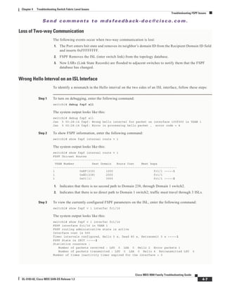
Step 4 Enter the following command to get information about why the interface is isolated:
switch2# show int fc1/8 trunk vsan
The system output looks like this:
switch2# show int fc1/8 trunk vsan
fc1/8 is trunking
Vsan 1 is up, FCID is 0x650000
Vsan 99 is down](https://image.slidesharecdn.com/tsgd-170311102023/85/Cisco-San-switch-troublehooting-Guide-89-320.jpg)

![Se n d c o m m e n t s t o m d s f e e d b a ck -d o c @ c i sc o . c o m .
5-7
Cisco MDS 9000 Family Troubleshooting Guide
OL-5183-02, Cisco MDS SAN-OS Release 1.3
Chapter 5 Troubleshooting IP Storage Issues
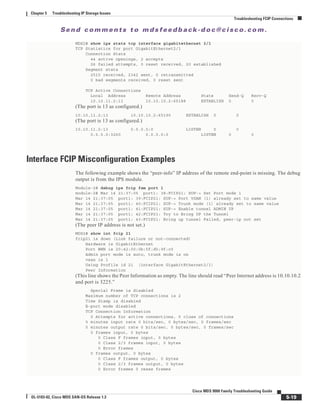
Troubleshooting FCIP Connections
Mar 10 21:41:04 ips: entity28: add to config pss
MDS2(config-profile)# ip address 10.10.11.2
Mar 10 21:41:15 ips: Dequeued mts msg MTS_OPC_IPS_FCIP_CMI_REQUEST(mts opc 3321, msg id
32258)
Mar 10 21:41:15 ips: entity28: IP address changed to 10.10.11.2
Mar 10 21:41:15 ips: entity28: IP 10.10.11.2 configured for interface GigabitEthernet2/8
Mar 10 21:41:15 ips: entity28: Apply the entity config and save to config pss
Mar 10 21:41:15 ips: entity28: add to config pss
MDS2(config-profile)# exit
MDS2(config)# interface fcip 28
Mar 10 21:41:46 ips: Dequeued mts msg MTS_OPC_IPS_FCIP_CMI_REQUEST(mts opc 3321, msg id
32358)
Mar 10 21:41:46 ips: Verified FCIP28 Create:0
Mar 10 21:41:46 ips: FCIP28: Verified Create:0
Mar 10 21:41:46 ips: Dequeued mts msg MTS_OPC_IPS_FCIP_CMI_REQUEST(mts opc 3321, msg id
32360)
Mar 10 21:41:46 ips: FCIP28: Creating FCIP tunnel
Mar 10 21:41:46 ips: FCIP28: add to admin pss
Mar 10 21:41:46 ips: FCIP28: add to run-time pss
Mar 10 21:41:46 ips: FCIP28: log: 0 phy: 0 state: 0 syslog: 0
MDS2(config-if)# use-profile 28
Mar 10 21:42:23 ips: Dequeued mts msg MTS_OPC_IPS_FCIP_CMI_REQUEST(mts opc 3321, msg id
32480)
Mar 10 21:42:23 ips: FCIP28: Process tunnel configuration event
Mar 10 21:42:23 ips: FCIP28: Change Entity-id from 0 to 28
Mar 10 21:42:23 ips: FCIP: Optimal IF lookup for GigabitEthernet2/8 is GigabitEthernet2/8
Mar 10 21:42:23 ips: FCIP28: bind with GigabitEthernet2/8 (phy GigabitEthernet2/8)
Mar 10 21:42:23 ips: FCIP28: Queueing bind tunnel to src if event to tunnel FSM resource:
0
Mar 10 21:42:23 ips: Locked fcip_if_fsm for MTS_OPC_IPS_FCIP_CMI_REQUEST(msg id 32480)
Mar 10 21:42:23 ips: FCIP28: Send bind for GigabitEthernet2/8 to PM (phy
GigabitEthernet2/8)
Mar 10 21:42:23 ips: FCIP28: add to run-time pss
Mar 10 21:42:23 ips: FCIP28: log: 2087000 phy: 2087000 state: 0 syslog: 0
Mar 10 21:42:23 ips: Dequeued mts msg MTS_OPC_IPS_CFG_FCIP_IF(mts opc 1905, msg id 7304)
Mar 10 21:42:23 ips: Hndlr MTS_OPC_IPS_CFG_FCIP_IF (mts_opc 1905 msg_id 7304)
Mar 10 21:42:23 ips: FCIP28: Got a tunnel param pull request from LC
Mar 10 21:42:23 ips: Added to pending queue event-id [29] event-cat [2]
Mar 10 21:42:23 ips: FCIP28: Queueing Process a Pull Request event to Pending queue
resource: 0
Mar 10 21:42:23 ips: Dequeued mts msg MTS_OPC_PM_FCIP_BIND(mts opc 335, msg id 32495)
Mar 10 21:42:23 ips: Hndlr MTS_OPC_PM_FCIP_BIND (mts_opc 335 msg_id 32495)
Mar 10 21:42:23 ips: FCIP28: Success received from PM for bind to GigabitEthernet2/8 (phy
GigabitEthernet2/8)
Mar 10 21:42:23 ips: FCIP28: Bind-resp event processing bind...
Mar 10 21:42:23 ips: FCIP28: add to run-time pss
Mar 10 21:42:23 ips: FCIP28: log: 2087000 phy: 2087000 state: 1 syslog: 0
Mar 10 21:42:23 ips: FCIP28: Last reference....
Mar 10 21:42:23 ips: FCIP28: Update the tunnel param and save to PSS
Mar 10 21:42:23 ips: FCIP28: add to admin pss
Mar 10 21:42:23 ips: FCIP28: add to run-time pss
Mar 10 21:42:23 ips: FCIP28: log: 2087000 phy: 2087000 state: 1 syslog: 0
Mar 10 21:42:23 ips: Unlocked fcip_if_fsm for MTS_OPC_IPS_FCIP_CMI_REQUEST(msg id 32480)
Mar 10 21:42:23 ips: Dequeued pending queue msg event_id [29] cat [2]
Mar 10 21:42:23 ips: (ips_demux) Mts Opcode is 1905, id is 7304
Mar 10 21:42:23 ips: FCIP28: Processing Pull Config Request
Mar 10 21:42:23 ips: FCIP28: Bound to entity 28 port: 3225 ip: 10.10.11.2](https://image.slidesharecdn.com/tsgd-170311102023/85/Cisco-San-switch-troublehooting-Guide-101-320.jpg)
![Se n d c o m m e n t s t o m d s f e e d b a ck -d o c @ c i sc o . c o m .
5-8
Cisco MDS 9000 Family Troubleshooting Guide
OL-5183-02, Cisco MDS SAN-OS Release 1.3
Chapter 5 Troubleshooting IP Storage Issues
Troubleshooting FCIP Connections
MDS2(config-if)# peer-info ipaddr 10.10.10.2
Mar 10 21:43:01 ips: Dequeued mts msg MTS_OPC_IPS_FCIP_CMI_REQUEST(mts opc 3321, msg id
32616)
Mar 10 21:43:01 ips: FCIP28: Process tunnel configuration event
Mar 10 21:43:01 ips: FCIP28: Change Peer IP from 0.0.0.0 to 10.10.10.2 and port from 3225
to 3225
Mar 10 21:43:01 ips: FCIP28: Queueing Set tunnel param event to tunnel FSM resource: 0
Mar 10 21:43:01 ips: Locked fcip_if_fsm for MTS_OPC_IPS_FCIP_CMI_REQUEST(msg id 32616)
Mar 10 21:43:01 ips: FCIP28: Send tunnel params to LC to DPP: 7
Mar 10 21:43:01 ips: Dequeued mts msg MTS_OPC_IPS_FCIP_SET_LC_TUNNEL_PARAM(mts opc 1897,
msg id 7358)
Mar 10 21:43:01 ips: Hndlr MTS_OPC_IPS_FCIP_SET_LC_TUNNEL_PARAM (mts_opc 1897 msg_id 7358)
Mar 10 21:43:01 ips: In handler : Received resp code: 0
Mar 10 21:43:01 ips: FCIP28: Received the tunnel params from LC
Mar 10 21:43:01 ips: FCIP28: Update the tunnel param and save to PSS
Mar 10 21:43:01 ips: FCIP28: add to admin pss
Mar 10 21:43:01 ips: FCIP28: add to run-time pss
Mar 10 21:43:01 ips: FCIP28: log: 2087000 phy: 2087000 state: 1 syslog: 0
Mar 10 21:43:01 ips: Unlocked fcip_if_fsm for MTS_OPC_IPS_FCIP_CMI_REQUEST(msg id 32616)
MDS2(config-if)#
MDS2(config-if)# no shut
MDS2(config-if)# Mar 10 21:43:32 ips: Dequeued mts msg
MTS_OPC_PM_LOGICAL_PORT_STATE_CHANGE_RANGE(mts opc 3114, msg id 32737)
Mar 10 21:43:32 ips: Hndlr MTS_OPC_PM_LOGICAL_PORT_STATE_CHANGE_RANGE (mts_opc 3114 msg_id
32737)
Mar 10 21:43:32 ips: Dequeued mts msg MTS_OPC_PM_LOGICAL_PORT_STATE_CHANGE_RANGE(mts opc
3114, msg id 32778)
Mar 10 21:43:32 ips: Hndlr MTS_OPC_PM_LOGICAL_PORT_STATE_CHANGE_RANGE (mts_opc 3114 msg_id
32778)
Mar 10 21:43:32 ips: Dequeued mts msg MTS_OPC_PM_LOGICAL_PORT_STATE_CHANGE_RANGE(mts opc
3114, msg id 32783)
Mar 10 21:43:32 ips: Hndlr MTS_OPC_PM_LOGICAL_PORT_STATE_CHANGE_RANGE (mts_opc 3114 msg_id
32783)
The following example shows the debug output from the supervisor of the FCIP tunnel.
MDS2(config)# int fcip 28
MDS2(config-if)# no shut
MDS2(config-if)# Mar 10 22:59:46 ips: fu_priority_select: - setting fd[3] for select call
- found data in FU_PSEL_Q_CAT_MTS queue, fd(3), usr_q_info(1)
Mar 10 22:59:46 ips: fu_priority_select_select_queue: round credit(0)
Mar 10 22:59:46 ips: curr_q - FU_PSEL_Q_CAT_CQ, usr_q_info(3), priority(4), credit(0),
empty
Mar 10 22:59:46 ips: Starting a new round
Mar 10 22:59:46 ips: fu_priority_select: returning FU_PSEL_Q_CAT_MTS queue, fd(3),
usr_q_info(1)
Mar 10 22:59:46 ips: Dequeued mts msg MTS_OPC_PM_LOGICAL_PORT_STATE_CHANGE_RANGE(mts opc
3114, msg id 47540)
Mar 10 22:59:46 ips: ips_mts_hdlr_pm_logical_port_state_change_range:
Mar 10 22:59:46 ips: Hndlr MTS_OPC_PM_LOGICAL_PORT_STATE_CHANGE_RANGE (mts_opc 3114 msg_id
47540)
Mar 10 22:59:46 ips: fu_fsm_execute_all: match_msg_id(0), log_already_open(0)
Mar 10 22:59:46 ips: fu_fsm_execute_all: null fsm_event_list
Mar 10 22:59:46 ips: fu_fsm_engine: mts msg
MTS_OPC_PM_LOGICAL_PORT_STATE_CHANGE_RANGE(msg_id 47540) dropped
Mar 10 22:59:46 ips: fu_priority_select: - setting fd[3] for select call - found data in
FU_PSEL_Q_CAT_MTS queue, fd(3), usr_q_info(1)
Mar 10 22:59:46 ips: fu_priority_select_select_queue: round credit(6)](https://image.slidesharecdn.com/tsgd-170311102023/85/Cisco-San-switch-troublehooting-Guide-102-320.jpg)
![Se n d c o m m e n t s t o m d s f e e d b a ck -d o c @ c i sc o . c o m .
5-9
Cisco MDS 9000 Family Troubleshooting Guide
OL-5183-02, Cisco MDS SAN-OS Release 1.3
Chapter 5 Troubleshooting IP Storage Issues
Troubleshooting FCIP Connections
Mar 10 22:59:46 ips: curr_q - FU_PSEL_Q_CAT_CQ, usr_q_info(3), priority(4), credit(3),
empty
Mar 10 22:59:46 ips: fu_priority_select: returning FU_PSEL_Q_CAT_MTS queue, fd(3),
usr_q_info(1)
Mar 10 22:59:46 ips: Dequeued mts msg MTS_OPC_PM_LOGICAL_PORT_STATE_CHANGE_RANGE(mts opc
3114, msg id 47589)
Mar 10 22:59:46 ips: ips_mts_hdlr_pm_logical_port_state_change_range:
Mar 10 22:59:46 ips: Hndlr MTS_OPC_PM_LOGICAL_PORT_STATE_CHANGE_RANGE (mts_opc 3114 msg_id
47589)
Mar 10 22:59:46 ips: fu_fsm_execute_all: match_msg_id(0), log_already_open(0)
Mar 10 22:59:46 ips: fu_fsm_execute_all: null fsm_event_list
Mar 10 22:59:46 ips: fu_fsm_engine: mts msg
MTS_OPC_PM_LOGICAL_PORT_STATE_CHANGE_RANGE(msg_id 47589) dropped
Mar 10 22:59:46 ips: fu_priority_select: - setting fd[3] for select call - found data in
FU_PSEL_Q_CAT_MTS queue, fd(3), usr_q_info(1)
Mar 10 22:59:46 ips: fu_priority_select_select_queue: round credit(4)
Mar 10 22:59:46 ips: curr_q - FU_PSEL_Q_CAT_CQ, usr_q_info(3), priority(4), credit(2),
empty
Mar 10 22:59:46 ips: fu_priority_select: returning FU_PSEL_Q_CAT_MTS queue, fd(3),
usr_q_info(1)
Mar 10 22:59:46 ips: Dequeued mts msg MTS_OPC_PM_LOGICAL_PORT_STATE_CHANGE_RANGE(mts opc
3114, msg id 47602)
Mar 10 22:59:46 ips: ips_mts_hdlr_pm_logical_port_state_change_range:
Mar 10 22:59:46 ips: Hndlr MTS_OPC_PM_LOGICAL_PORT_STATE_CHANGE_RANGE (mts_opc 3114 msg_id
47602)
Mar 10 22:59:46 ips: fu_fsm_execute_all: match_msg_id(0), log_already_open(0)
Mar 10 22:59:46 ips: fu_fsm_execute_all: null fsm_event_list
Mar 10 22:59:46 ips: fu_fsm_engine: mts msg
MTS_OPC_PM_LOGICAL_PORT_STATE_CHANGE_RANGE(msg_id 47602) dropped
The following example shows the debug output from the IPS module of the FCIP tunnel.
MDS2# attach module 2
module-2# debug ips fcip fsm port 8
(This is the Gigabit Ethernet port 2/8.)
Mar 13 19:18:19 port8: 2700:FCIP28: Received new TCP connection from peer:
10.10.10.2:65455
Mar 13 19:18:19 port8: 2701:FCIP: (fcip_de_create): DE = 0xdc02ca40
Mar 13 19:18:19 port8: 2702:FCIP28: Create a DE 0xdc02ca40 for this tunnel
Mar 13 19:18:19 port8: 2703:FCIP28: Bind the DE 0xdc02ca40 [1] to tunnel LEP 0x801ebac0
Mar 13 19:18:19 port8: 2704:FCIP28: Bind DE 1 to TCP-hdl 0xdc489800
Mar 13 19:18:19 port8: 2705:FCIP28: Bind DE 1 to eport 0x801eaaa0
Mar 13 19:18:19 port8: 2706:FCIP28: bind de 1 in eport 0x801eaaa0, hash = 1 num-conn: 2
Mar 13 19:18:19 port8: 2707:FCIP28: Received new TCP connection from peer:
10.10.10.2:65453
Mar 13 19:18:19 port8: 2708:FCIP: (fcip_de_create): DE = 0xdc02cb40
Mar 13 19:18:19 port8: 2709:FCIP28: Create a DE 0xdc02cb40 for this tunnel
Mar 13 19:18:19 port8: 2710:FCIP28: Bind the DE 0xdc02cb40 [2] to tunnel LEP 0x801ebac0
Mar 13 19:18:19 port8: 2711:FCIP28: Bind DE 2 to TCP-hdl 0xdc488800
Mar 13 19:18:19 port8: 2712:FCIP28: Bind DE 2 to eport 0x801eaaa0
Mar 13 19:18:19 port8: 2713:FCIP28: bind de 2 in eport 0x801eaaa0, hash = 2 num-conn: 2
Mar 13 19:18:19 port8: 2714:FCIP28: Send LINK UP to SUP
Mar 13 19:18:20 port8: 2715:FCIP28: *** Received eisl frame in E mode
Mar 13 19:18:20 port8: 2716:FCIP28: SUP-> Set trunk mode: 2
Mar 13 19:18:20 port8: 2717:FCIP28: Change the operational mode to TRUNK
Mar 13 19:18:20 port8: 2718:FCIP28: Tunnel bringup debounce timer callbeck, try to bring
up tunnel
Mar 13 19:18:20 port8: 2719:FCIP28: Tunnel is already in oper UP state, don't try to
bring up again...](https://image.slidesharecdn.com/tsgd-170311102023/85/Cisco-San-switch-troublehooting-Guide-103-320.jpg)
![Se n d c o m m e n t s t o m d s f e e d b a ck -d o c @ c i sc o . c o m .
5-12
Cisco MDS 9000 Family Troubleshooting Guide
OL-5183-02, Cisco MDS SAN-OS Release 1.3
Chapter 5 Troubleshooting IP Storage Issues
Troubleshooting FCIP Connections
TCP Active Connections
Local Address Remote Address State Send-Q Recv-Q
10.10.10.2:3225 10.10.11.2:65519 ESTABLISH 0 0
(This is used for F control traffic only.)
10.10.10.2:3225 10.10.11.2:65521 ESTABLISH 87568 0
(Send-Q increasing during read-only test.)
10.10.10.2:3225 0.0.0.0:0 LISTEN 0 0
(The TCP listen port is ready for new TCP connections.)
You can use the following command to verify that traffic is incrementing on Gigabit Ethernet port of the
FCIP tunnel.
MDS1# show ips stats mac interface gigabitethernet 2/8
Ethernet MAC statistics for port GigabitEthernet2/8
Hardware Transmit Counters
1074898 frame 1095772436 bytes
0 collisions, 0 late collisions, 0 excess collisions
0 bad frames, 0 FCS error, 0 abort, 0 runt, 0 oversize
Hardware Receive Counters
33488196 bytes, 298392 frames, 277 multicasts, 16423 broadcasts
0 bad, 0 runt, 0 CRC error, 0 length error
0 code error, 0 align error, 0 oversize error
Software Counters
298392 received frames, 1074898 transmit frames
0 frames soft queued, 0 current queue, 0 max queue
0 dropped, 0 low memory
Traffic statistics can be verified on the internal ASIC chip on each Gigabit Ethernet port.
MDS1# show ips stats flamingo interface gigabitethernet 2/8
Flamingo ASIC Statistics for port GigabitEthernet2/8
Hardware Egress Counters
2312 Good, 0 bad protocol, 0 bad header cksum, 0 bad FC CRC
(Good frames and CRC error frames can be monitored.)
Hardware Ingress Counters
(Verify good increments on the active tunnel.)
2312 Good, 0 protocol error, 0 header checksum error
0 FC CRC error, 0 iSCSI CRC error, 0 parity error
Software Egress Counters
2312 good frames, 0 bad header cksum, 0 bad FIFO SOP
0 parity error, 0 FC CRC error, 0 timestamp expired error
0 unregistered port index, 0 unknown internal type
0 RDL, 0 RDL too big RDL, 0 TDL ttl_1
3957292257 idle poll count, 0 loopback, 0 FCC PQ, 0 FCC EQ
Flow Control: 0 [0], 0 [1], 0 [2], 0 [3]
Software Ingress Counters
2312 Good frames, 0 header cksum error, 0 FC CRC error
0 iSCSI CRC error, 0 descriptor SOP error, 0 parity error
0 frames soft queued, 0 current Q, 0 max Q, 0 low memory
0 out of memory drop, 0 queue full drop
0 RDL, 0 too big RDL drop
Flow Control: 0 [0], 0 [1], 0 [2], 0 [3]
On the next few pages are screen captures taken with Ethereal, of TCP connection being established, and
FCIP tunnels. Note that FCIP tunnel activation is the same as an FC EISL becoming active (such as ELP,
ESC, and EFP). The following traces were captured after configuration on both MDS 9000 Family
switches, and the last “no shutdown” was entered on switch MDS1. All settings are default (for
example, SACK is disabled, the TCP window is set to 64K).](https://image.slidesharecdn.com/tsgd-170311102023/85/Cisco-San-switch-troublehooting-Guide-106-320.jpg)
![Se n d c o m m e n t s t o m d s f e e d b a ck -d o c @ c i sc o . c o m .
5-21
Cisco MDS 9000 Family Troubleshooting Guide
OL-5183-02, Cisco MDS SAN-OS Release 1.3
Chapter 5 Troubleshooting IP Storage Issues
Troubleshooting FCIP Connections
MDS1# show fcip profile 21
FCIP Profile 21
Internet Address is 10.10.10.2 (interface GigabitEthernet2/1)
Listen Port is 3225
TCP parameters
SACK is disabled
PMTU discover is enabled, reset timeout is 3600 sec
Keep alive is 60 sec
Minimum retransmission timeout is 300 ms
Maximum number of re-transmissions is 4
Advertised window size is 64 KB
The following debug output is from switch MDS2.
Mar 14 23:26:07 port1: 1340:FCIP21: Start TCP listener with peer: 10.10.10.2:3225
Mar 14 23:26:07 port1: 1341:FCIP: Create a new listener object for 10.10.11.2:3225
Mar 14 23:26:07 port1: 1342:FCIP: Create FCIP Listener with local info: 10.10.11.2:3225
Mar 14 23:26:07 port1: 1343:FCIP21: Create a DE 0xd802d140 for this tunnel
Mar 14 23:26:07 port1: 1344:FCIP21: Bind the DE 0xd802d140 [1] to tunnel LEP 0x80111570
Mar 14 23:26:07 port1: 1345:FCIP21: Start the active connection [1] to 10.10.10.2:13
Mar 14 23:26:07 port1: 1346:FCIP21: Create a DE 0xd802cdc0 for this tunnel
Mar 14 23:26:07 port1: 1347:FCIP21: Bind the DE 0xd802cdc0 [2] to tunnel LEP 0x80111570
Mar 14 23:26:07 port1: 1348:FCIP21: Start the active connection [2] to 10.10.10.2:13
(The switch is attempting to create a TCP connection on port 13. The creation port must match the TCP
listen port on the remote end point.)
Mar 14 23:26:07 port1: 1349:FCIP21: Active Connect creation FAILED [1]
Mar 14 23:26:07 port1: 1350:FCIP21: Delete the DE [1]0xd802d140
Mar 14 23:26:07 port1: 1351:FCIP21: Delete the DE object [1] 0xd802d140
Mar 14 23:26:07 port1: 1352:FCIP21: Try 7 to bring up the tunnel
Mar 14 23:26:07 port1: 1353:FCIP21: Start the bringup tunnel timer, timeout: 64000
Mar 14 23:26:07 port1: 1354:FCIP21: Active Connect creation FAILED [2]
Mar 14 23:26:07 port1: 1355:FCIP21: Delete the DE [2]0xd802cdc0
Mar 14 23:26:07 port1: 1356:FCIP21: Set lep operation state to DOWN
Mar 14 23:26:07 port1: 1357:FCIP21: Delete the DE object [2] 0xd802cdc0
Mar 14 23:26:07 port1: 1358:FCIP21: Try 8 to bring up the tunnel
Mar 14 23:26:07 port1: 1359:FCIP21: Start the bringup tunnel timer, timeout: 128000
MDS2(config-if)# peer-info ipaddr 10.10.10.2 port 3225
(This changes the start active connection port to match the default port 3225.)
Or you can use this command:
MDS2(config-if)# no peer-info ipaddr 10.10.10.2 port 13
(Removing port 13 will also set it to the default of 3225.)
MDS2# show int fcip 21
fcip21 is trunking
Hardware is GigabitEthernet
Port WWN is 20:42:00:0b:5f:d5:9f:c0
Peer port WWN is 20:42:00:05:30:00:59:de
Admin port mode is auto, trunk mode is on
Port mode is TE
vsan is 1
Trunk vsans (allowed active) (1-2)
Trunk vsans (operational) (1-2)
Trunk vsans (up) (1-2)
Trunk vsans (isolated) ()
Trunk vsans (initializing) ()
Using Profile id 21 (interface GigabitEthernet2/1)
Peer Information
Peer Internet address is 10.10.10.2 and port is 3225](https://image.slidesharecdn.com/tsgd-170311102023/85/Cisco-San-switch-troublehooting-Guide-115-320.jpg)
![Se n d c o m m e n t s t o m d s f e e d b a ck -d o c @ c i sc o . c o m .
5-23
Cisco MDS 9000 Family Troubleshooting Guide
OL-5183-02, Cisco MDS SAN-OS Release 1.3
Chapter 5 Troubleshooting IP Storage Issues
Troubleshooting FCIP Connections
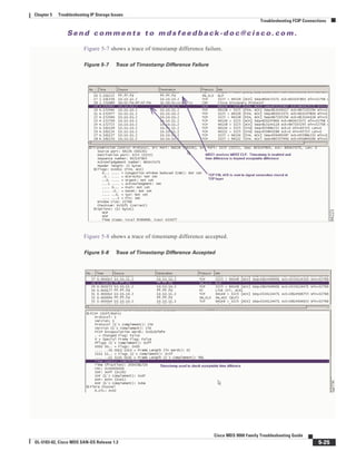
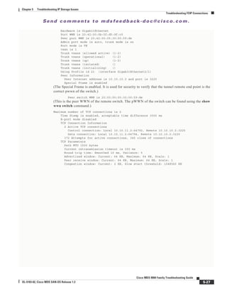
The following example shows a time stamp acceptable difference failure, or no NTP server connected to
synchronize clocks. When using time stamps, the MDS switch must be a synchronized clock. NTP is
configurable on the MDS 9000 switch.
MDS2(config)# int fcip 21
MDS2(config-if)# time-stamp
module-2# debug ips fcip fsm port 1
Mar 15 00:01:35 port1: 3248:FCIP21: IPS-> Enable timestamp acceptable difference 1000
(Timestamp is enabled under the interface FCIP. The default acceptable difference is 1000.)
Mar 15 00:01:35 port1: 3249:FCIP21: IPS-> acc diff in sec: 0x1 frac: 0x0
Mar 15 00:01:35 port1: 3250:FCIP21: Sending response code: 0
Mar 15 00:01:48 port1: 3251:FCIP21: Time stamp tolerance check failed local time:
0x3e726d6c2db994b7 tolerance: 0x100000000 recv time: 0x3e7251ace20db73a
(The timestamp difference failed the acceptable difference.)
Mar 15 00:01:48 port1: 3252:FCIP21: Time stamp tolerance check failed local time:
0x3e726d6c2db994b7 tolerance: 0x100000000 recv time: 0x3e7251ace20db73a
Mar 15 00:01:48 port1: 3253:FCIP21: Time stamp tolerance check failed local time:
0x3e726d6c2db994b7 tolerance: 0x100000000 recv time: 0x3e7251ace20db73a
<<< cut >>>
Mar 15 00:01:48 port1: 3290:FCIP21: Time stamp tolerance check failed local time:
0x3e726d6c2db994b7 tolerance: 0x100000000 recv time: 0x3e7251ace20db73a
Mar 15 00:01:48 port1: 3291:FCIP21: (fcip_de_rcv): Previous partial packet -
Concatenating
Mar 15 00:01:48 port1: 3292:FCIP21: Time stamp tolerance check failed local time:
0x3e726d6c2db994b7 tolerance: 0x100000000 recv time: 0x3e7251ace20db73a
Mar 15 00:01:48 port1: 3293:FCIP21: FCIP frame len 0x300 is not within correct range <<<
?? >>>
Mar 15 00:01:48 port1: 3294:FCIP21: Delete the DE [2]0xd802d680
Mar 15 00:01:48 port1: 3295:FCIP21: replace the eport entry at index: 1
Mar 15 00:01:48 port1: 3296:FCIP21: DE [-670902656] 0x00000002 terminate tcp connection
0xd8072800
(The TCP connection is disconnected because the timestamp difference is too large.)
Mar 15 00:01:48 port1: 3297:FCIP21: Delete the DE object [2] 0xd802d680
Mar 15 00:01:48 port1: 3298:FCIP21: Delete the DE [1]0xd802cf00
Mar 15 00:01:48 port1: 3299:FCIP21: Unregister from flamingo port_index: 0x21
Mar 15 00:01:48 port1: 3300:FCIP21: Send Link down to SUP
Mar 15 00:01:48 port1: 3301:FCIP21: Start the bringup tunnel timer, timeout: 18470
Mar 15 00:01:48 port1: 3302:FCIP21: replace the eport entry at index: 0
Mar 15 00:01:48 port1: 3303:FCIP21: Set lep operation state to DOWN
Mar 15 00:01:48 port1: 3304:FCIP21: DE [-670904576] 0x00000001 terminate tcp connection
0xd8072c00
Mar 15 00:01:48 port1: 3305:FCIP21: Delete the DE object [1] 0xd802cf00
Mar 15 00:01:50 port1: 3306:FCIP21: Received new TCP connection from peer:
10.10.10.2:65066
(The TCP connection begins trying to re-establish the connection.)
Mar 15 00:01:50 port1: 3307:FCIP21: Tunnel is not ADMIN UP state, reject new TCP
connection from 10.10.10.2:65066
Mar 15 00:01:50 port1: 3308:FCIP21: Received new TCP connection from peer:
10.10.10.2:65064
Mar 15 00:01:50 port1: 3309:FCIP21: Tunnel is not ADMIN UP state, reject new TCP
connection from 10.10.10.2:65064
Mar 15 00:01:56 port1: 3310:FCIP21: SUP-> Set Port mode 1
Mar 15 00:01:56 port1: 3311:FCIP21: SUP-> Port VSAN (1) already set to same value
Mar 15 00:01:56 port1: 3312:FCIP21: SUP-> Set trunk mode: 1
Mar 15 00:01:56 port1: 3313:FCIP21: SUP-> Enable tunnel ADMIN UP
Mar 15 00:01:56 port1: 3314:FCIP21: Try to Bring UP the Tunnel
Mar 15 00:01:56 port1: 3315:FCIP21: tunnel bring-up debounce timer set, wait for timer to
pop
(Connect the NTP server or synchronized clocks, or increase the acceptable difference.)](https://image.slidesharecdn.com/tsgd-170311102023/85/Cisco-San-switch-troublehooting-Guide-117-320.jpg)
![Se n d c o m m e n t s t o m d s f e e d b a ck -d o c @ c i sc o . c o m .
5-24
Cisco MDS 9000 Family Troubleshooting Guide
OL-5183-02, Cisco MDS SAN-OS Release 1.3
Chapter 5 Troubleshooting IP Storage Issues
Troubleshooting FCIP Connections
module-2# debug ips fcip fsm port 1
module-2#
Jan 14 14:22:08 port1: 854886:FCIP21: IPS-> Enable timestamp acceptable difference 2000
Jan 14 14:22:08 port1: 854887:FCIP21: IPS-> acc diff in sec: 0x2 frac: 0x0
(The timestamp acceptable difference passes and the tunnel continues to be brought up.)
module-2#
module-2# Jan 14 14:22:39 port1: 854932:FCIP21: Received new TCP connection from peer:
10.10.10.2:64172
Jan 14 14:22:39 port1: 854933:FCIP21: Create a DE 0xd802d5c0 for this tunnel
Jan 14 14:22:39 port1: 854934:FCIP21: Bind the DE 0xd802d5c0 [1] to tunnel LEP 0x80111570
Jan 14 14:22:39 port1: 854935:FCIP21: Bind DE 1 to TCP-hdl 0xd8071000
Jan 14 14:22:39 port1: 854936:FCIP21: Bind DE 1 to eport 0x80110550
Jan 14 14:22:39 port1: 854937:FCIP21: bind de 1 in eport 0x80110550, hash = 1 num-conn: 2
Jan 14 14:22:39 port1: 854938:FCIP21: Received new TCP connection from peer: 10
.10.10.2:64170
Jan 14 14:22:39 port1: 854939:FCIP21: Create a DE 0xd802c900 for this tunnel
Jan 14 14:22:39 port1: 854940:FCIP21: Bind the DE 0xd802c900 [2] to tunnel LEP
0x80111570
Jan 14 14:22:39 port1: 854941:FCIP21: Bind DE 2 to TCP-hdl 0xd8070000
Jan 14 14:22:39 port1: 854942:FCIP21: Bind DE 2 to eport 0x80110550
Jan 14 14:22:39 port1: 854943:FCIP21: bind de 2 in eport 0x80110550, hash = 2 n
um-conn: 2
Jan 14 14:22:39 port1: 854944:FCIP21: Send LINK UP to SUP
Jan 14 14:22:39 port1: 854945:FCIP21: *** Received eisl frame in E mode
Jan 14 14:22:39 port1: 854946:FCIP21: SUP-> Set trunk mode: 2
Jan 14 14:22:39 port1: 854947:FCIP21: Change the operational mode to TRUNK
MDS2# show int fcip 21
fcip21 is trunking
Hardware is GigabitEthernet
Port WWN is 20:42:00:0b:5f:d5:9f:c0
Peer port WWN is 20:42:00:05:30:00:59:de
Admin port mode is auto, trunk mode is on
Port mode is TE
vsan is 1
Trunk vsans (allowed active) (1-2)
Trunk vsans (operational) (1-2)
Trunk vsans (up) (1-2)
Trunk vsans (isolated) ()
Trunk vsans (initializing) ()
Using Profile id 21 (interface GigabitEthernet2/1)
Peer Information
Peer Internet address is 10.10.10.2 and port is 3225
Special Frame is disabled
Maximum number of TCP connections is 2
Time Stamp is enabled, acceptable time difference 2000 ms
B-port mode disabled
TCP Connection Information](https://image.slidesharecdn.com/tsgd-170311102023/85/Cisco-San-switch-troublehooting-Guide-118-320.jpg)
![Se n d c o m m e n t s t o m d s f e e d b a ck -d o c @ c i sc o . c o m .
5-26
Cisco MDS 9000 Family Troubleshooting Guide
OL-5183-02, Cisco MDS SAN-OS Release 1.3
Chapter 5 Troubleshooting IP Storage Issues
Troubleshooting FCIP Connections
FCIP Special Frame Tunnel Creation and Monitoring
Previous FCIP tunnel configuration must be completed before adding FCIP Special Frame configuration.
This section describes how to correctly configure and show an FCIP tunnel with a Special Frame.
MDS2# show wwn switch
Switch WWN is 20:00:00:0b:5f:d5:9f:c0
(You’ll need the WWN of each MDS 9000 switch end point.)
MDS1(config)# int fcip 21
MDS1(config-if)# special-frame peer-wwn 20:00:00:0b:5f:d5:9f:c0 profile-id 1
(This enables the Special Frame that is used in the creation of the FCIP tunnel.)
MDS1# show wwn switch
Switch WWN is 20:00:00:05:30:00:59:de
MDS2(config)# int fcip 21
MDS2(config-if)# special-frame peer-wwn 20:00:00:05:30:00:59:de profile-id 1
module-2#
Jan 14 15:25:38 port1: 857314:FCIP21: SUP-> Set Port mode 1
Jan 14 15:25:38 port1: 857315:FCIP21: SUP-> Port VSAN (1) already set to same value
Jan 14 15:25:38 port1: 857316:FCIP21: SUP-> Trunk mode (1) already set to same value
Jan 14 15:25:38 port1: 857317:FCIP21: SUP-> Enable tunnel ADMIN UP
Jan 14 15:25:38 port1: 857318:FCIP21: Try to Bring UP the Tunnel
Jan 14 15:25:38 port1: 857319:FCIP21: Start TCP listener with peer: 10.10.10.2:3225
Jan 14 15:25:38 port1: 857320:FCIP: Create a new listener object for 10.10.11.2:3225
Jan 14 15:25:38 port1: 857321:FCIP: Create FCIP Listener with local info: 10.10.11.2:3225
Jan 14 15:25:38 port1: 857322:FCIP21: Create a DE 0xd802cd00 for this tunnel
Jan 14 15:25:38 port1: 857323:FCIP21: Bind the DE 0xd802cd00 [1] to tunnel LEP 0x80111570
Jan 14 15:25:38 port1: 857324:FCIP21: Start the active connection [1] to 10.10.10.2:3225
Jan 14 15:25:38 port1: 857325:FCIP21: Create a DE 0xd802db40 for this tunnel
Jan 14 15:25:38 port1: 857326:FCIP21: Bind the DE 0xd802db40 [2] to tunnel LEP 0x80111570
Jan 14 15:25:38 port1: 857327:FCIP21: Start the active connection [2] to 10.10.10.2:3225
Jan 14 15:25:38 port1: 857328:FCIP21: Active Connect creation SUCCEEDED [1]
Jan 14 15:25:38 port1: 857329:FCIP21: Bind DE 1 to TCP-hdl 0xd8072c00
Jan 14 15:25:38 port1: 857330:FCIP21: Setup for Special Frame handling: I'm Originator
(This begins the Special Frame setup of the Originator.)
Jan 14 15:25:38 port1: 857331:FCIP21: Send the SF as Originator & wait for response
(The Special Frame is sent.)
Jan 14 15:25:38 port1: 857332:FCIP21: Setup timer to wait for SF
Jan 14 15:25:38 port1: 857333:FCIP21: Active Connect creation SUCCEEDED [2]
(The Special Frame is correctly configured with the WWN of the remote MDS 9000 switch.)
Jan 14 15:25:38 port1: 857334:FCIP21: Bind DE 2 to TCP-hdl 0xd8072000
Jan 14 15:25:38 port1: 857335:FCIP21: Setup for Special Frame handling: I'm Originator
Jan 14 15:25:38 port1: 857336:FCIP21: Send the SF as Originator & wait for response
Jan 14 15:25:38 port1: 857337:FCIP21: Setup timer to wait for SF
Jan 14 15:25:38 port1: 857338:FCIP21: processing SF frame, I'm Originator
Jan 14 15:25:38 port1: 857339:FCIP21: Bind DE 1 to eport 0x80110550
Jan 14 15:25:38 port1: 857340:FCIP21: bind de 1 in eport 0x80110550, hash = 1 num-conn: 2
Jan 14 15:25:38 port1: 857341:FCIP21: processing SF frame, I'm Originator
Jan 14 15:25:38 port1: 857342:FCIP21: Bind DE 2 to eport 0x80110550
Jan 14 15:25:38 port1: 857343:FCIP21: bind de 2 in eport 0x80110550, hash = 2 num-conn: 2
Jan 14 15:25:38 port1: 857344:FCIP21: Send LINK UP to SUP
Jan 14 15:25:39 port1: 857345:FCIP21: SUP-> Set trunk mode: 2
Jan 14 15:25:39 port1: 857346:FCIP21: Change the operational mode to TRUNK
Jan 14 15:25:39 port1: 857347:FCIP21: *** Received non-eisl frame in TE mode 64 64
MDS2# show int fcip 21
fcip21 is trunking](https://image.slidesharecdn.com/tsgd-170311102023/85/Cisco-San-switch-troublehooting-Guide-120-320.jpg)
![Se n d c o m m e n t s t o m d s f e e d b a ck -d o c @ c i sc o . c o m .
5-28
Cisco MDS 9000 Family Troubleshooting Guide
OL-5183-02, Cisco MDS SAN-OS Release 1.3
Chapter 5 Troubleshooting IP Storage Issues
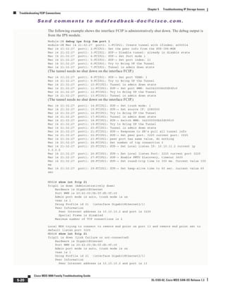
Troubleshooting FCIP Connections
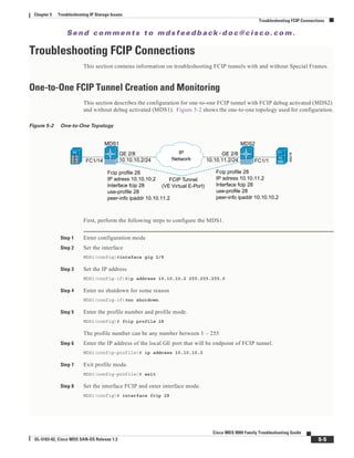
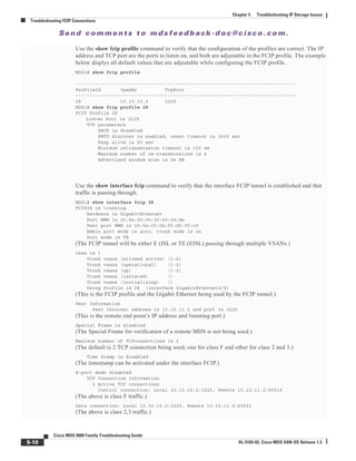
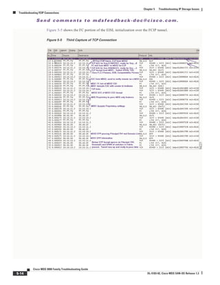
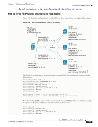
Figure 5-9 shows a trace of an FCIP tunnel with a Special Frame.
Figure 5-9 Trace of FCIP Tunnel with a Special Frame
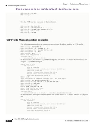
Special Frame Misconfiguration Examples
The following example shows an incorrect peer WWN when using Special Frame.
module-2# Jan 14 15:14:30 port1: 855278:FCIP21: SUP-> Set Port mode 1
Jan 14 15:14:30 port1: 855279:FCIP21: SUP-> Port VSAN (1) already set to same value
Jan 14 15:14:30 port1: 855280:FCIP21: SUP-> Trunk mode (1) already set to same
Jan 14 15:14:30 port1: 855281:FCIP21: SUP-> Enable tunnel ADMIN UP
Jan 14 15:14:30 port1: 855282:FCIP21: Try to Bring UP the Tunnel
Jan 14 15:14:30 port1: 855283:FCIP21: Start TCP listener with peer: 10.10.10.2:3225
Jan 14 15:14:30 port1: 855284:FCIP: Create a new listener object for 10.10.11.2:3225
Jan 14 15:14:30 port1: 855285:FCIP: Create FCIP Listener with local info: 10.10.11.2:3225
Jan 14 15:14:30 port1: 855286:FCIP21: Create a DE 0xd802d240 for this tunnel
Jan 14 15:14:30 port1: 855287:FCIP21: Bind the DE 0xd802d240 [1] to tunnel LEP 0x80111570
Jan 14 15:14:30 port1: 855288:FCIP21: Start the active connection [1] to 10.10.10.2:3225
Jan 14 15:14:30 port1: 855289:FCIP21: Create a DE 0xd802d200 for this tunnel
Jan 14 15:14:30 port1: 855290:FCIP21: Bind the DE 0xd802d200 [2] to tunnel LEP 0x80111570
Jan 14 15:14:30 port1: 855291:FCIP21: Start the active connection [2] to 10.10.10.2:3225
Jan 14 15:14:30 port1: 855292:FCIP21: Active Connect creation SUCCEEDED [1]
Jan 14 15:14:30 port1: 855293:FCIP21: Bind DE 1 to TCP-hdl 0xd8072c00
Jan 14 15:14:30 port1: 855294:FCIP21: Setup for Special Frame handling: I'm Originator
Jan 14 15:14:30 port1: 855295:FCIP21: Send the SF as Originator & wait for response
Jan 14 15:14:30 port1: 855296:FCIP21: Setup timer to wait for SF
Jan 14 15:14:30 port1: 855297:FCIP21: Active Connect creation SUCCEEDED [2]
Jan 14 15:14:30 port1: 855298:FCIP21: Bind DE 2 to TCP-hdl 0xd8072000
Jan 14 15:14:30 port1: 855299:FCIP21: Setup for Special Frame handling: I'm Originator
Jan 14 15:14:30 port1: 855300:FCIP21: Send the SF as Originator & wait for response
Jan 14 15:14:30 port1: 855301:FCIP21: Setup timer to wait for SF
Jan 14 15:14:30 port1: 855302:FCIP21: TCP Received a close connection [1] reason 1
Jan 14 15:14:30 port1: 855303:FCIP21: Delete the DE [1]0xd802d240](https://image.slidesharecdn.com/tsgd-170311102023/85/Cisco-San-switch-troublehooting-Guide-122-320.jpg)
![Se n d c o m m e n t s t o m d s f e e d b a ck -d o c @ c i sc o . c o m .
5-29
Cisco MDS 9000 Family Troubleshooting Guide
OL-5183-02, Cisco MDS SAN-OS Release 1.3
Chapter 5 Troubleshooting IP Storage Issues
Troubleshooting FCIP Connections
Jan 14 15:14:30 port1: 855304:FCIP21: DE [-670903744] 0x00000001 terminate tcp connection
0xd8072c00
Jan 14 15:14:30 port1: 855305:FCIP21: Delete the DE object [1] 0xd802d240
Jan 14 15:14:30 port1: 855306:FCIP21: lep not bound, close only de [1]
Jan 14 15:14:30 port1: 855307:FCIP21: TCP Received a close connection [2] reason 1
Jan 14 15:14:30 port1: 855308:FCIP21: Delete the DE [2]0xd802d200
Jan 14 15:14:30 port1: 855309:FCIP21: Set lep operation state to DOWN
Jan 14 15:14:30 port1: 855310:FCIP21: Start the bringup tunnel timer, timeout: 38740
Jan 14 15:14:30 port1: 855311:FCIP21: DE [-670903808] 0x00000002 terminate tcp connection
0xd8072000
Jan 14 15:14:30 port1: 855312:FCIP21: Delete the DE object [2] 0xd802d200
Jan 14 15:14:30 port1: 855313:FCIP21: lep not bound, close only de [2]
Jan 14 15:14:31 port1: 855314:FCIP21: Received new TCP connection from peer:
10.10.10.2:64050
Jan 14 15:14:31 port1: 855315:FCIP21: Create a DE 0xd802d080 for this tunnel
Jan 14 15:14:31 port1: 855316:FCIP21: Bind the DE 0xd802d080 [1] to tunnel LEP 0x80111570
Jan 14 15:14:31 port1: 855317:FCIP21: Bind DE 1 to TCP-hdl 0xd8072000
Jan 14 15:14:31 port1: 855318:FCIP21: Setup for Special Frame handling: I'm Responder
Jan 14 15:14:31 port1: 855319:FCIP21: Setup timer to wait for SF
Jan 14 15:14:31 port1: 855320:FCIP21: processing SF frame, I'm Responder
Jan 14 15:14:31 port1: 855321:FCIP21: Source FC fabric name in SF (0x20000005300059de)
does not match LEP's peer fabric WWN (0x20010005300059df)
Jan 14 15:14:31 port1: 855322:FCIP21: Delete the DE [1]0xd802d080
Jan 14 15:14:31 port1: 855323:FCIP21: Set lep operation state to DOWN
Jan 14 15:14:31 port1: 855324:FCIP21: DE [-670904192] 0x00000001 terminate tcp connection
0xd8072000
Jan 14 15:14:31 port1: 855325:FCIP21: Delete the DE object [1] 0xd802d080
Jan 14 15:14:31 port1: 855326:FCIP21: Received new TCP connection from peer:
10.10.10.2:64048
Jan 14 15:14:31 port1: 855327:FCIP21: Create a DE 0xd802d200 for this tunnel
Jan 14 15:14:31 port1: 855328:FCIP21: Bind the DE 0xd802d200 [1] to tunnel LEP 0x80111570
Jan 14 15:14:31 port1: 855329:FCIP21: Bind DE 1 to TCP-hdl 0xd8072c00
Jan 14 15:14:31 port1: 855330:FCIP21: Setup for Special Frame handling: I'm Responder
Jan 14 15:14:31 port1: 855331:FCIP21: Setup timer to wait for SF
Jan 14 15:14:31 port1: 855332:FCIP21: processing SF frame, I'm Responder
Jan 14 15:14:31 port1: 855333:FCIP21: Source FC fabric name in SF (0x20000005300059de)
does not match LEP's peer fabric WWN (0x20010005300059df)
Jan 14 15:14:31 port1: 855334:FCIP21: Delete the DE [1]0xd802d200
Jan 14 15:14:31 port1: 855335:FCIP21: Set lep operation state to DOWN
Jan 14 15:14:31 port1: 855336:FCIP21: DE [-670903808] 0x00000001 terminate tcp connection
0xd8072c00
Jan 14 15:14:31 port1: 855337:FCIP21: Delete the DE object [1] 0xd802d200
Jan 14 15:14:37 port1: 855338:FCIP21: Received new TCP connection from peer:
10.10.10.2:64046
Jan 14 15:14:37 port1: 855339:FCIP21: Create a DE 0xd802d5c0 for this tunnel
Jan 14 15:14:37 port1: 855340:FCIP21: Bind the DE 0xd802d5c0 [1] to tunnel LEP 0x80111570
Jan 14 15:14:37 port1: 855341:FCIP21: Bind DE 1 to TCP-hdl 0xd8071000
Jan 14 15:14:37 port1: 855342:FCIP21: Setup for Special Frame handling: I'm Responder
Jan 14 15:14:37 port1: 855343:FCIP21: Setup timer to wait for SF
Jan 14 15:14:37 port1: 855344:FCIP21: processing SF frame, I'm Responder
Jan 14 15:14:37 port1: 855345:FCIP21: Source FC fabric name in SF (0x20000005300059de)
does not match LEP's peer fabric WWN (0x20010005300059df)
Jan 14 15:14:37 port1: 855346:FCIP21: Delete the DE [1]0xd802d5c0
Jan 14 15:14:37 port1: 855347:FCIP21: Set lep operation state to DOWN
Jan 14 15:14:37 port1: 855348:FCIP21: DE [-670902848] 0x00000001 terminate tcp connection
0xd8071000
Jan 14 15:14:37 port1: 855349:FCIP21: Delete the DE object [1] 0xd802d5c0
Jan 14 15:14:37 port1: 855350:FCIP21: Received new TCP connection from peer:
10.10.10.2:64044
Jan 14 15:14:37 port1: 855351:FCIP21: Create a DE 0xd802cac0 for this tunnel
Jan 14 15:14:37 port1: 855352:FCIP21: Bind the DE 0xd802cac0 [1] to tunnel LEP 0x80111570
Jan 14 15:14:37 port1: 855353:FCIP21: Bind DE 1 to TCP-hdl 0xd8071400
Jan 14 15:14:37 port1: 855354:FCIP21: Setup for Special Frame handling: I'm Responder
Jan 14 15:14:37 port1: 855355:FCIP21: Setup timer to wait for SF](https://image.slidesharecdn.com/tsgd-170311102023/85/Cisco-San-switch-troublehooting-Guide-123-320.jpg)
![Se n d c o m m e n t s t o m d s f e e d b a ck -d o c @ c i sc o . c o m .
5-30
Cisco MDS 9000 Family Troubleshooting Guide
OL-5183-02, Cisco MDS SAN-OS Release 1.3
Chapter 5 Troubleshooting IP Storage Issues
Troubleshooting FCIP Connections
Jan 14 15:14:37 port1: 855356:FCIP21: processing SF frame, I'm Responder
Jan 14 15:14:37 port1: 855357:FCIP21: Source FC fabric name in SF (0x20000005300059de)
does not match LEP's peer fabric WWN (0x20010005300059df)
Jan 14 15:14:37 port1: 855358:FCIP21: Delete the DE [1]0xd802cac0
Jan 14 15:14:37 port1: 855359:FCIP21: Set lep operation state to DOWN
Jan 14 15:14:37 port1: 855360:FCIP21: DE [-670905664] 0x00000001 terminate tcp connection
0xd8071400
Jan 14 15:14:37 port1: 855361:FCIP21: Delete the DE object [1] 0xd802cac0
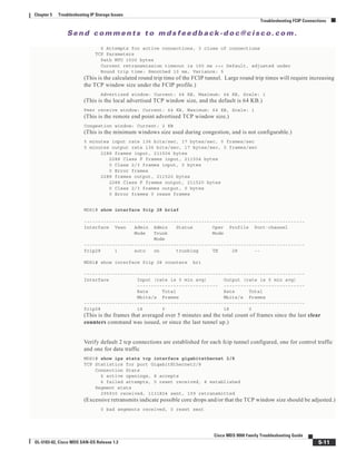
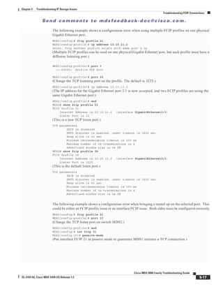
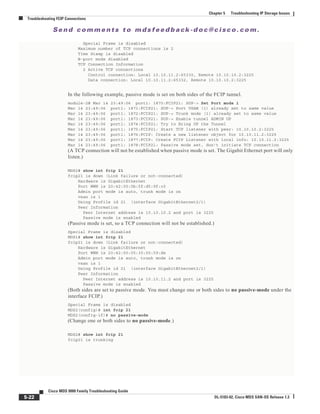
Figure 5-10 shows a trace of an incorrect remote switch WWN using a Special Frame
Figure 5-10 Trace of Incorrect Remote Switch WWN Using a Special Frame](https://image.slidesharecdn.com/tsgd-170311102023/85/Cisco-San-switch-troublehooting-Guide-124-320.jpg)
![Se n d c o m m e n t s t o m d s f e e d b a ck -d o c @ c i sc o . c o m .
5-31
Cisco MDS 9000 Family Troubleshooting Guide
OL-5183-02, Cisco MDS SAN-OS Release 1.3
Chapter 5 Troubleshooting IP Storage Issues
Troubleshooting iSCSI Issues
Troubleshooting iSCSI Issues
There are several types of issues you can experience with iSCSI, including the following:
• Troubleshooting iSCSI Authentication, page 5-31
• Configuring Authentication, page 5-32
• Troubleshooting Username/Password Configuration, page 5-33
• Troubleshooting Radius Configuration, page 5-33
• Troubleshooting Radius Routing Configuration, page 5-36
• Troubleshooting Dynamic iSCSI Configuration, page 5-36
Troubleshooting iSCSI Authentication
iSCSI user login authentication is required with the Cisco MDS 9000 Family switch. There are two ways
of the getting iSCSI users authenticated: either locally configured the in the switch’s configuration file,
or using the Radius server database.
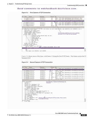
Figure 5-11 shows a successful iSCSI login for the Windows 2000 driver.
Figure 5-11 Sucessful iSCSI Login Status Window
On Solaris systems, a successful login is found in the /var/adm/messages directory, and should look
similar to the following example:
Mar 14 12:53:23 ca-sun1 iscsid[12745]: [ID 702911 daemon.notice] discovery process for
172.22.91.223 finished, exiting
Mar 14 12:58:45 ca-sun1 iscsid[12802]: [ID 448557 daemon.notice] logged into
DiscoveryAddress 172.22.91.223:3260 isid 023d0040
Mar 14 12:58:45 ca-sun1 iscsid[12802]: [ID 702911 daemon.notice] iSCSI target 2 =
iqn.com.domainname.vrrp-11.gw.21000020375aff77 at0
Mar 14 12:58:45 ca-sun1 iscsid[12809]: [ID 529321 daemon.notice] logged into target
iqn.com.domainname.vrrp-11.gw.21000020375aff77 7
Mar 14 12:58:45 ca-sun1 iscsid[12802]: [ID 702911 daemon.notice] iSCSI target 3 =
iqn.com.domainname.vrrp-11.gw.21000020374baf02 at0
Mar 14 12:58:45 ca-sun1 iscsid[12810]: [ID 529321 daemon.notice] logged into target
iqn.com.domainname.vrrp-11.gw.21000020374baf02 7](https://image.slidesharecdn.com/tsgd-170311102023/85/Cisco-San-switch-troublehooting-Guide-125-320.jpg)
![Se n d c o m m e n t s t o m d s f e e d b a ck -d o c @ c i sc o . c o m .
5-32
Cisco MDS 9000 Family Troubleshooting Guide
OL-5183-02, Cisco MDS SAN-OS Release 1.3
Chapter 5 Troubleshooting IP Storage Issues
Troubleshooting iSCSI Issues
Figure 5-12 shows a failed iSCSI login for the Windows 2000 driver.
Figure 5-12 Failed iSCSI Login Status Window
On Solaris systems, a failed login is found in the /var/adm/messages directory and should look similar
to the following example.
Mar 14 11:44:42 ca-sun1 iscsid[12561]: [ID 702911 daemon.notice] login rejected: initiator
error (01)
Mar 14 11:44:42 ca-sun1 iscsid[12561]: [ID 702911 daemon.error] Hard discovery login
failure to 172.22.91.223:3260 - exiting
Mar 14 11:44:42 ca-sun1 iscsid[12561]: [ID 702911 daemon.notice] discovery process for
172.22.91.223 finished, exiting
Configuring Authentication
Whenever you experience a login failure, use the show authentication command to see if the iSCSI
authentication is correctly defined. A sample of local authentication should look like this:
switch# show authentication
authentication method:none
console:not enabled
telnet/ssh:not enabled
authentication method:radius
console:not enabled
telnet/ssh:not enabled
iscsi:not enabled
authentication method:local <<<<<<<<<<<<<<<<<<<<
console:enabled
telnet/ssh:enabled
iscsi:enabled <<<<<<<<<<<<<<<<<<<<
switch#
If iSCSI is configured for radius authentication, it should looks like this:
switch# show authentication
authentication method:none
console:not enabled
telnet/ssh:not enabled
authentication method:radius <<<<<<<<<<<<<<<<<<<
console:not enabled](https://image.slidesharecdn.com/tsgd-170311102023/85/Cisco-San-switch-troublehooting-Guide-126-320.jpg)
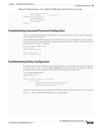
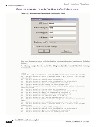
![Se n d c o m m e n t s t o m d s f e e d b a ck -d o c @ c i sc o . c o m .
5-35
Cisco MDS 9000 Family Troubleshooting Guide
OL-5183-02, Cisco MDS SAN-OS Release 1.3
Chapter 5 Troubleshooting IP Storage Issues
Troubleshooting iSCSI Issues
Mar 4 23:16:25 securityd: got back the return value of global radius configuration
operation:success
Mar 4 23:16:25 securityd: closing RADIUS pss configuration
Mar 4 23:16:25 securityd: opening radius configuration for group:default
Mar 4 23:16:25 securityd: opened the configuration successfully
Mar 4 23:16:25 securityd: GETNEXT request for radius index:0 addr:
Mar 4 23:16:25 securityd: got some reply from 171.71.49.197
Mar 4 23:16:25 securityd: verified the response from:171.71.49.197
Mar 4 23:16:25 securityd: RADIUS server sent accept for authentication request for
user002
Mar 4 23:16:25 securityd: got some reply from 171.71.49.197
Mar 4 23:16:25 securityd: verified the response from:171.71.49.197
Mar 4 23:16:25 securityd: RADIUS server sent accept for authentication request for
user002
The example above shows that the iSCSI client has been authenticated 3 times, first for the switch login,
and the second and third times for the SCSI drive login. The switch sends Radius attributes 1, 3, 4, 5,
6, 60 and 61 to the Radius server. The Radius server only needs to respond with request accept or
request reject.
The following example shows a radius authentication.
639 2003y3m14d 15h12m48s ------------------------------------------------
640 2003y3m14d 15h12m48s Message Type=Access_Request
641 2003y3m14d 15h12m48s ID=243, Length=90
642 2003y3m14d 15h12m48s User name=user002
643 2003y3m14d 15h12m48s NAS IP address=2887147911
644 2003y3m14d 15h12m48s CHAP password=‰j÷<¸Wøøë-K–ëÙ<]
645 2003y3m14d 15h12m48s CHAP challenge=n8NÝgø§"__Ó4}Ôx
646 2003y3m14d 15h12m48s NAS port=1426
647 2003y3m14d 15h12m48s NAS port type=5
648 2003y3m14d 15h12m48s Service type=8
649 2003y3m14d 15h12m48s User (user002) authenticate OK.
650 2003y3m14d 15h12m54s ------------------------------------------------
651 2003y3m14d 15h12m54s Message Type=Access_Request
652 2003y3m14d 15h12m54s ID=60, Length=90
653 2003y3m14d 15h12m54s User name=user002
654 2003y3m14d 15h12m54s NAS IP address=2887147911
655 2003y3m14d 15h12m54s CHAP password=_¿Éò_à!_AëC0__`õ
656 2003y3m14d 15h12m54s CHAP challenge=_/Ô½Ÿ×!âßÈ 4_´ZH
657 2003y3m14d 15h12m54s NAS port=1426
658 2003y3m14d 15h12m54s NAS port type=5
659 2003y3m14d 15h12m54s Service type=8
660 2003y3m14d 15h12m54s User (user002) authenticate OK.
661 2003y3m14d 15h12m54s ------------------------------------------------
662 2003y3m14d 15h12m54s Message Type=Access_Request
663 2003y3m14d 15h12m54s ID=179, Length=90
664 2003y3m14d 15h12m54s User name=user002
665 2003y3m14d 15h12m54s NAS IP address=2887147911
666 2003y3m14d 15h12m54s CHAP password=-–5Àùrfàxh
667 2003y3m14d 15h12m54s CHAP challenge=#ùÊÝü{_"__“´_Ux
668 2003y3m14d 15h12m54s NAS port=1426
669 2003y3m14d 15h12m54s NAS port type=5
670 2003y3m14d 15h12m54s Service type=8
671 2003y3m14d 15h12m54s User (user002) authenticate OK.](https://image.slidesharecdn.com/tsgd-170311102023/85/Cisco-San-switch-troublehooting-Guide-129-320.jpg)
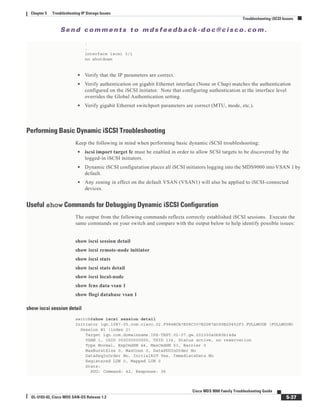
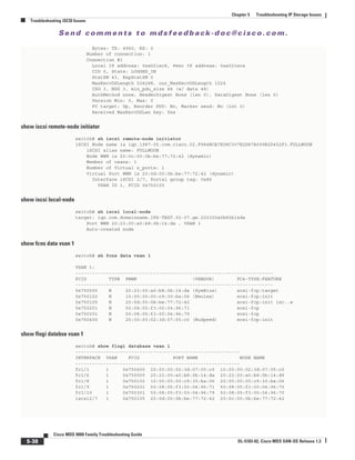
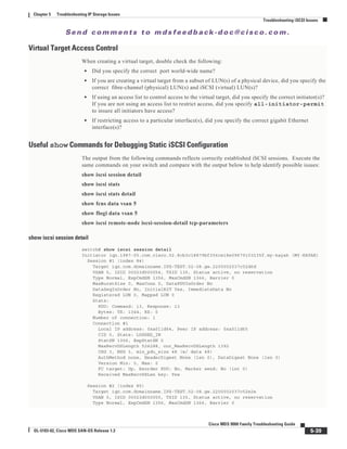
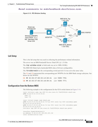
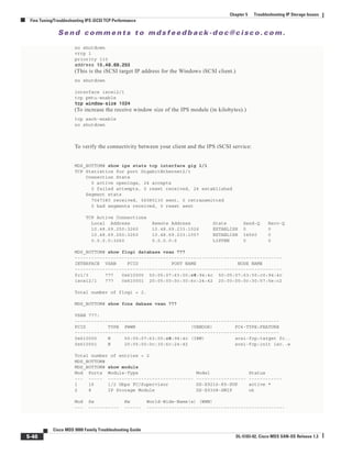
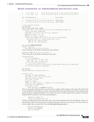
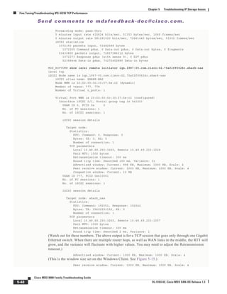
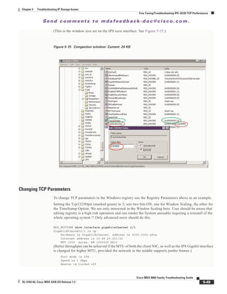
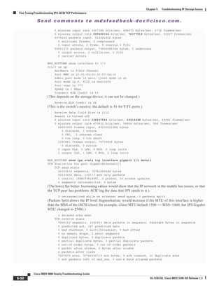

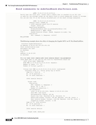
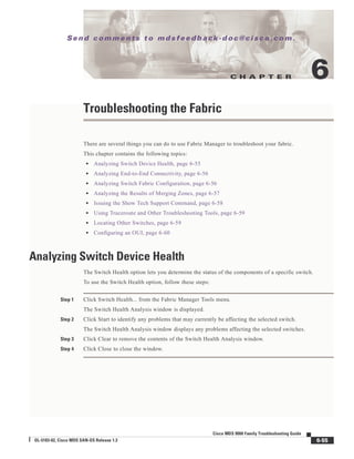
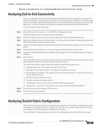
![Se n d c o m m e n t s t o m d s f e e d b a ck -d o c @ c i sc o . c o m .
6-59
Cisco MDS 9000 Family Troubleshooting Guide
OL-5183-02, Cisco MDS SAN-OS Release 1.3
Chapter 6 Troubleshooting the Fabric
Using Traceroute and Other Troubleshooting Tools
Using Traceroute and Other Troubleshooting Tools
You can use the following options on the Tools menu to verify connectivity to a selected object or to
open other management tools:
• Traceroute—Verify connectivity between two end devices that are currently selected on the Map
pane.
• Device Manager— Launch the Device Manager for the switch selected on the Map pane.
• Command Line Interface—Open a Telnet or SSH session for the switch selected on the Map pane.
To use the Traceroute option to verify connectivity, follow these steps:
Step 1 Select two or more endpoints on the Fabric Manager map.
Step 2 Click Traceroute from the Tools menu, or right-click one of the endpoints and click Trace Route from
the pop-up menu.
The Traceroute window is displayed.
Step 3 Change the timeout value if the default (10 seconds) is too short or too long.
Step 4 Click Start.
Step 5 The results of the Traceroute operation appear in the Results box.
Locating Other Switches
The Locate Switches option uses SNMPv2 and discovers devices responding to SNMP requests with the
read-only community string public.
To locate switches that are not included in the currently discovered fabric, follow these steps:
Step 1 Choose Locate Devices by Subnet from the Fabric Manager File menu.
You see the Locate Switches dialog box.
Step 2 Enter a range of specific addresses belonging to a specific subnet which limit the research for the
switches. To look for a Cisco MDS 9000 switch belonging to subnet 192.168.199.0, use the following
string:
192.168.100.[1-254]
Multiple ranges can be specified, separated by commas. For example, to look for all the devices in the
two subnets 192.168.199.0 and 192.169.100.0, use the following string:
192.168.100.[1-254], 192.169.100.[1-254]
Step 3 Enter the appropriate read community string in the Read Community field.
The default value for this string is “public.”
Step 4 Click Display Cisco MDS 9000 Only to display only the Cisco MDS 9000 Family switches in your
network fabric.
Step 5 Click Search to discover switches and devices in your network fabric. You see the results of the discovery
in the Locate Switches window.](https://image.slidesharecdn.com/tsgd-170311102023/85/Cisco-San-switch-troublehooting-Guide-153-320.jpg)
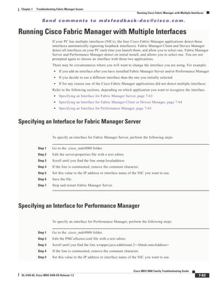
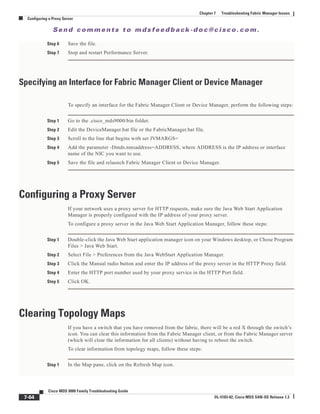


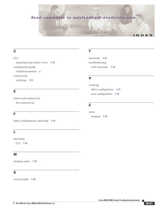


![[WEBINAR] Retos de la Virtualización.](https://cdn.slidesharecdn.com/ss_thumbnails/webinarvirtualizacin-121031144304-phpapp01-thumbnail.jpg?width=640&height=640&fit=bounds)