This document provides an administration guide for Cisco Small Business IP Phone models SPA 301, 303, 501G, 502G, 504G, 508G, 509G, 525G/525G2, and WIP310. It contains information on getting started with the phones, including upgrading firmware, determining the IP address, and using the web-based configuration utility. The document also covers configuring lines, extensions, call features, audio settings, SIP, security, and provisioning of the IP phone models.

![Customizing Cisco SPA and Wireless IP Phones
Enabling Call Features
3
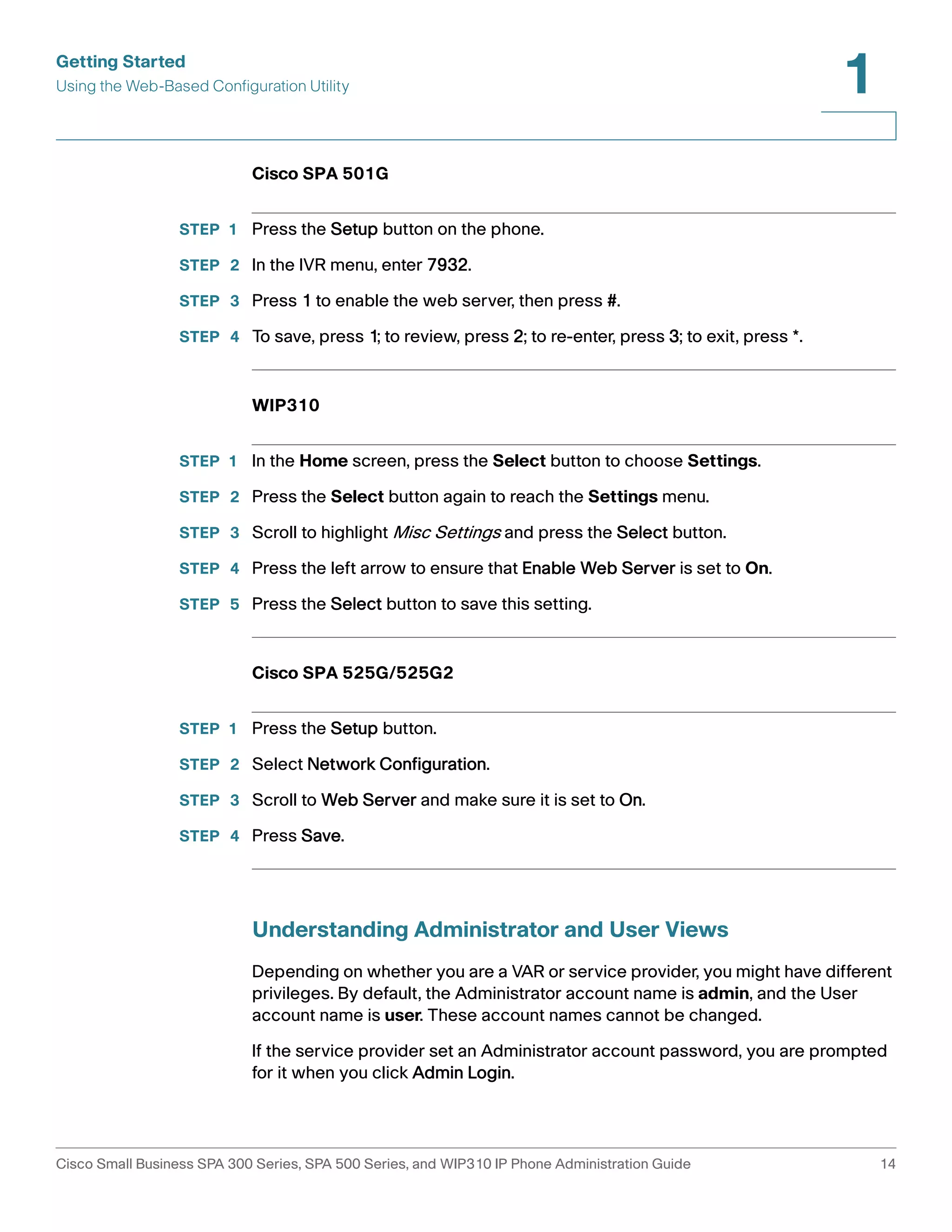
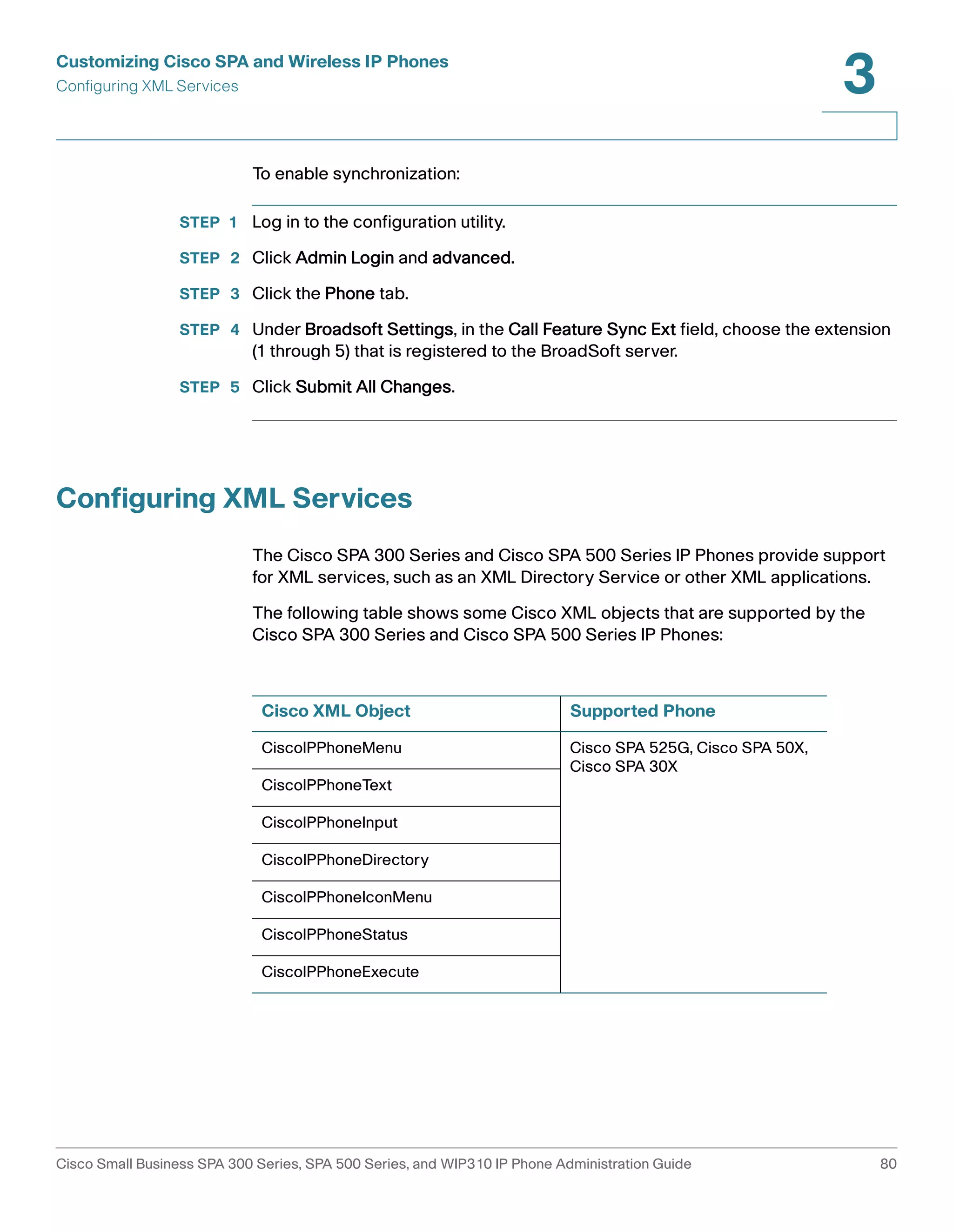
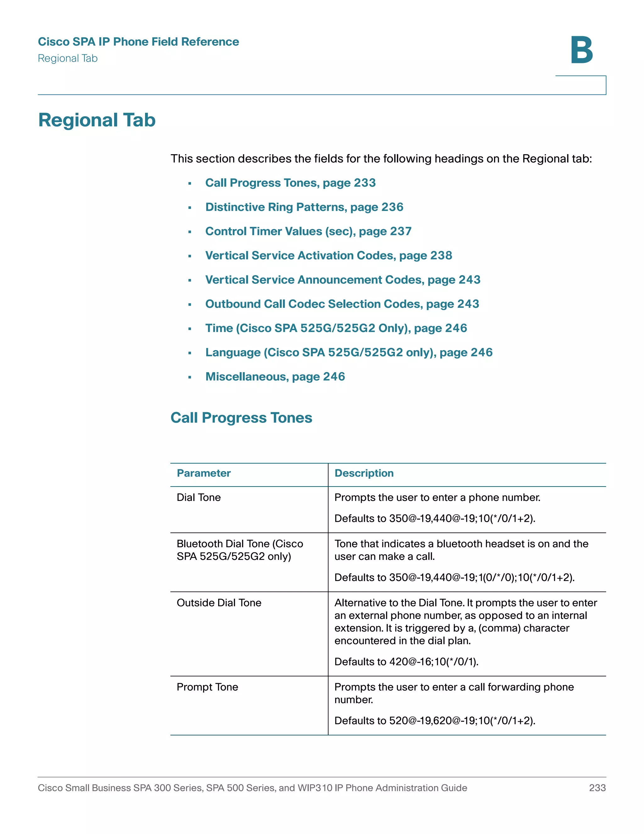
STEP 4 Under Supplementary Services, in the Auto Answer Page field, choose yes.
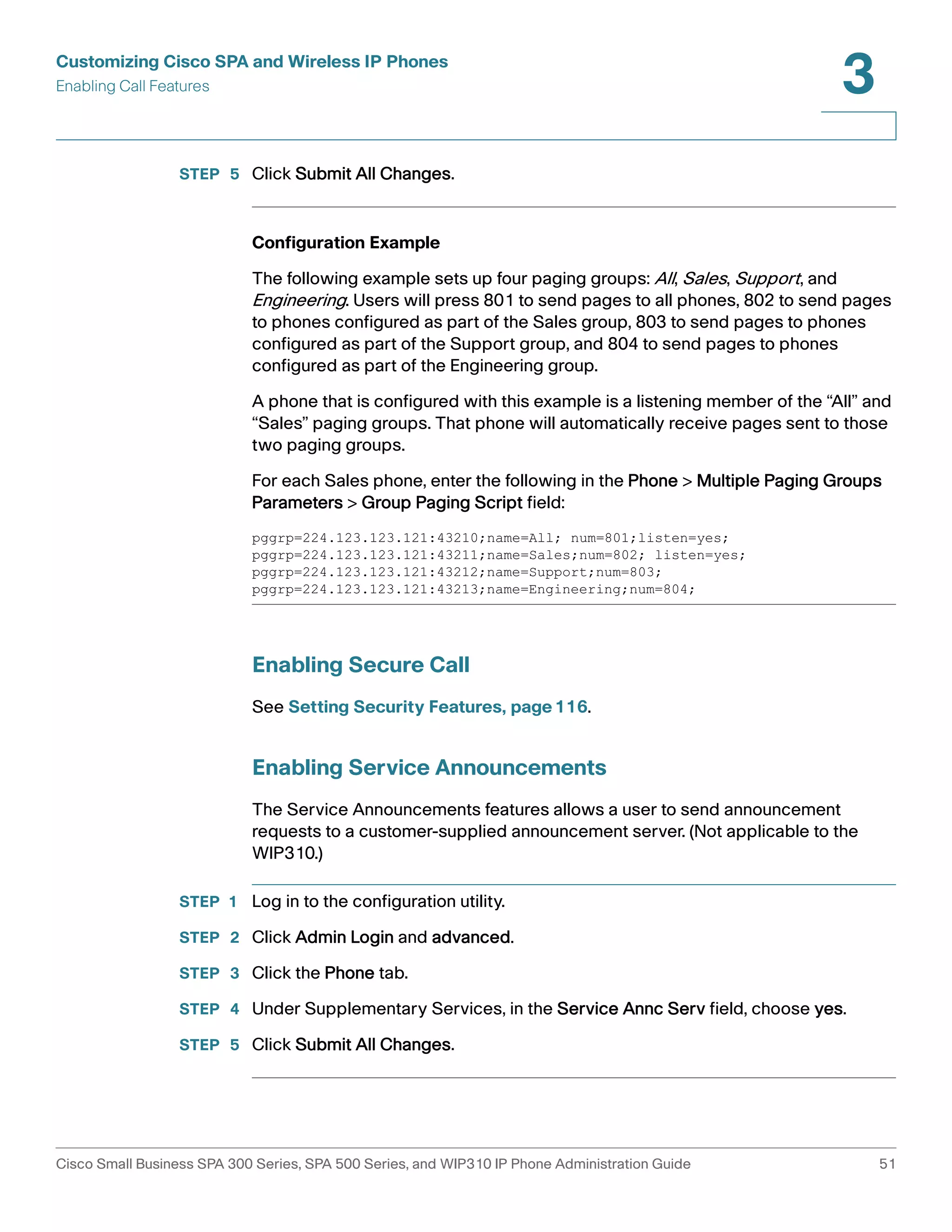
STEP 5 Click Submit All Changes. The phone reboots.
Configuring Paging Groups
You can configure a phone as part of a paging group. Users can then direct pages
to specific groups of phones.
Limitations:
• A phone can be a listening member of no more than two paging groups.
• No more than five paging groups can be configured on a phone.
To configure a phone as part of a paging group:
STEP 1 Log in to the configuration utility for the phone.
STEP 2 Click Admin Login and advanced.
STEP 3 Click the Phone tab.
STEP 4 Under Multiple Paging Group Parameters, enter the paging commands into the
Group Paging Script field. The syntax is as follows:
pggrp=ip-address:port;[name=xxx;]num=xxx;[listen={yes|no}]];
Where:
• IP address: Multicast IP address of the phone that will listen for and receive
pages.
• port: Port on which to page; you must use different ports for each paging
group. All phones in the same paging group must use the same port
number.
• name (optional): The name of the paging group.
• num: The number users will dial to access the paging group; must be unique
to the group.
• listen: If the phone being configured is a listening member of the page
group. A phone can be a listening member of a maximum of two groups. If
no value is entered, the default is to not listen as a member of this group.
Cisco Small Business SPA 300 Series, SPA 500 Series, and WIP310 IP Phone Administration Guide 50](https://image.slidesharecdn.com/ciscospa303-administrationguide-141015151631-conversion-gate02/75/Cisco-spa303-administration-guide-62-2048.jpg)
![Customizing Cisco SPA and Wireless IP Phones
Customizing Phone Softkeys
3
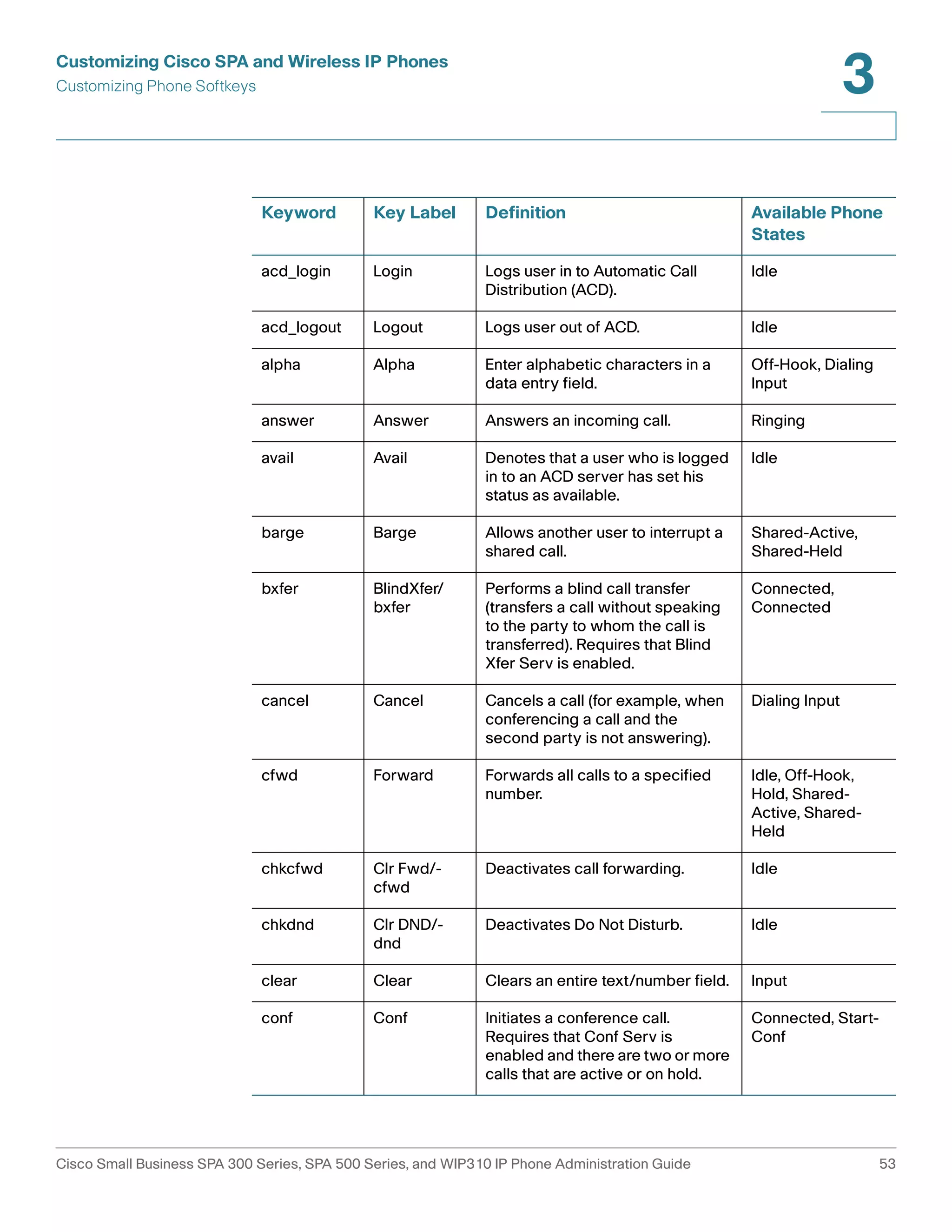
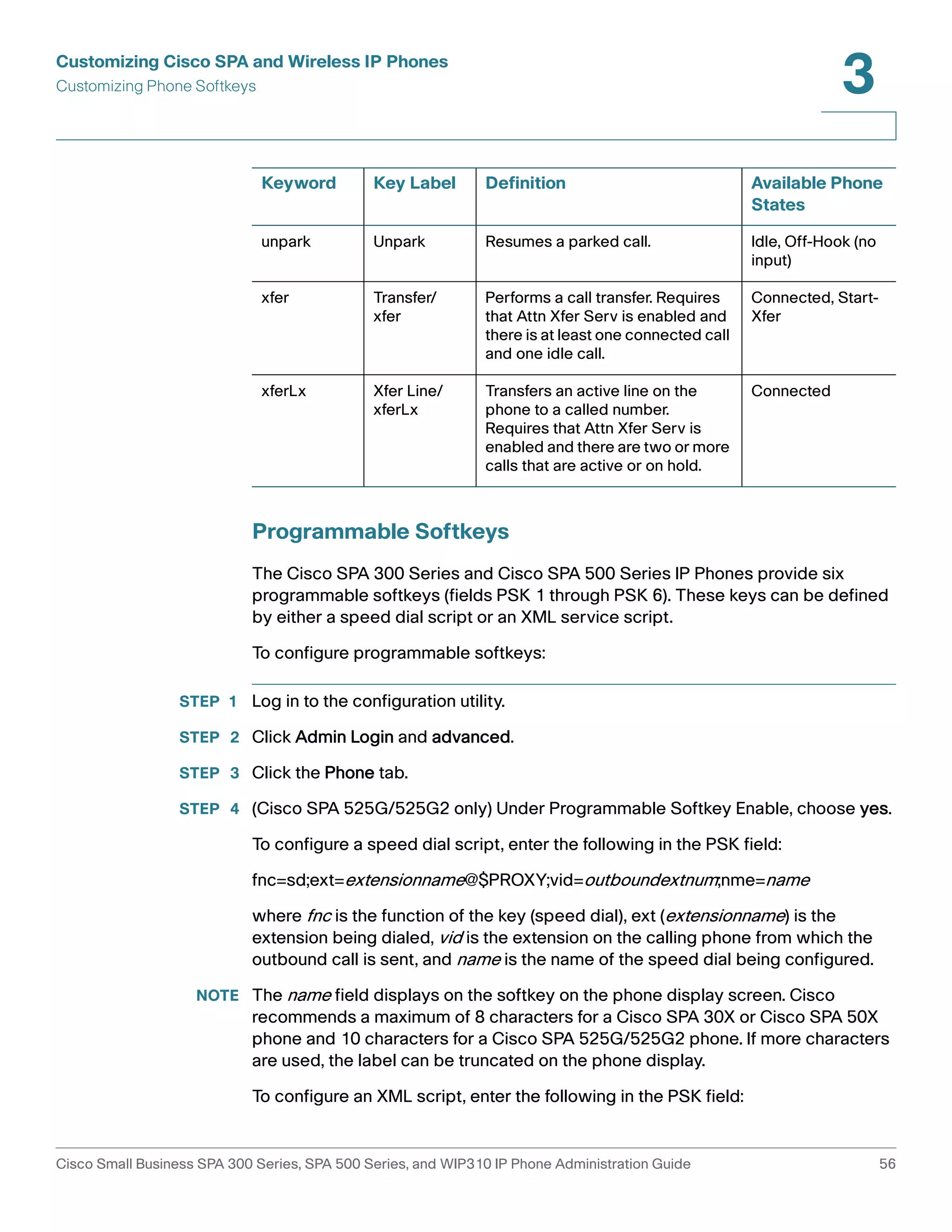
Customizing Phone Softkeys
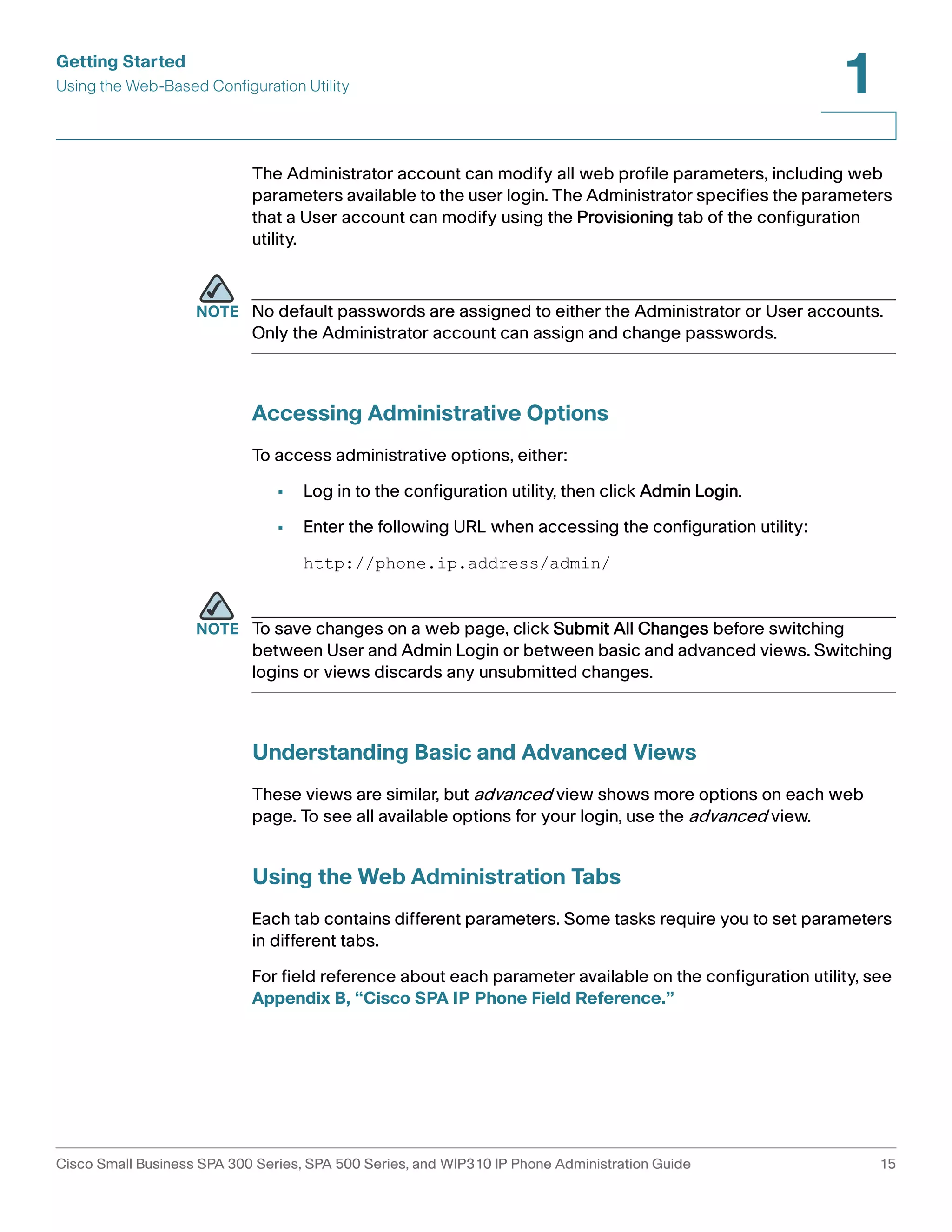
NOTE This feature is unavailable on the Cisco SPA 300 Series and Cisco SPA 500 Series
IP Phones using SPCP.
The Cisco SPA 300 Series and Cisco SPA 500 Series IP phones have four softkeys
on the screen that, when pressed, perform certain actions. (The Cisco SPA 301
and Cisco SPA 501 do not have any softkeys.)
The default softkeys (when the phone is in an idle state) are Redial, Directory, Call
Forward, and Do Not Disturb. Other softkeys are available during specific call
states (for example, if a call is on hold, the Resume softkey displays).
You can customize the softkeys displayed on the phone. To program softkeys:
STEP 1 Log in to the configuration utility.
STEP 2 Click Admin Login and advanced.
STEP 3 Click the Phone tab.
STEP 4 (Cisco SPA 525G/525G2 only) Under Programmable Softkey Enable, choose yes.
STEP 5 Edit the softkeys depending on the call state in which you want the softkey to
display. See the following table for information about softkeys.
STEP 6 Click Submit All Changes.
In the Programmable Softkeys section, each phone state is displayed and the
softkeys that are available to display during that state are listed. Each softkey is
separated by a semicolon. Softkeys are shown in the format:
softkeyname|[position]
where softkeyname is the name of the key and position is where the key is
displayed on the phone screen. Positions are numbered, with position one
displayed on the lower left of the screen, followed by positions two through four.
Additional positions are accessed by pressing the right arrow key on the phone. If
no position is given for a softkey, the key will “float” and appears in the first
available empty position on the screen.
NOTE On the Cisco SPA 525G/SPA525G2, in the Off Hook State, the More softkey is fixed
in position 4 and cannot be changed.
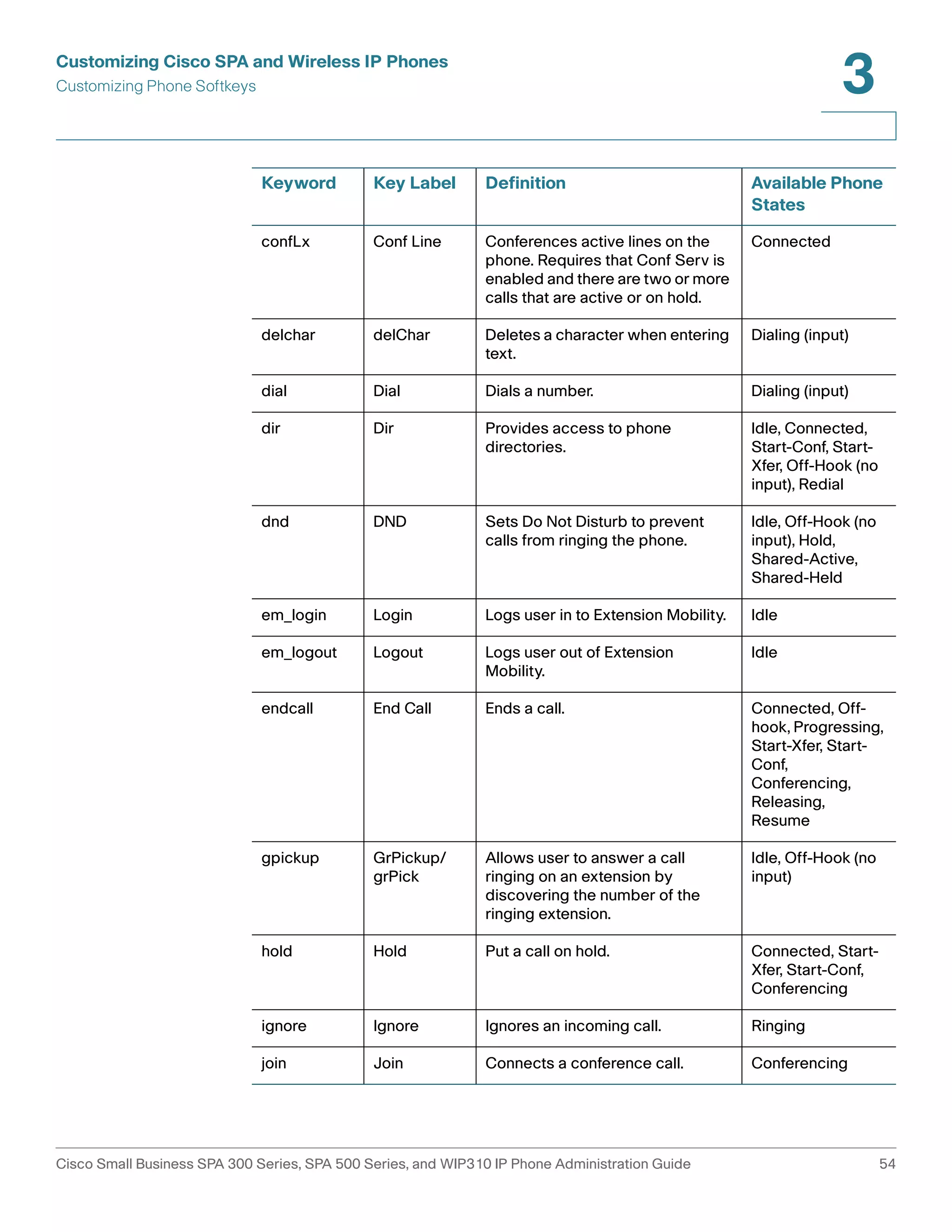
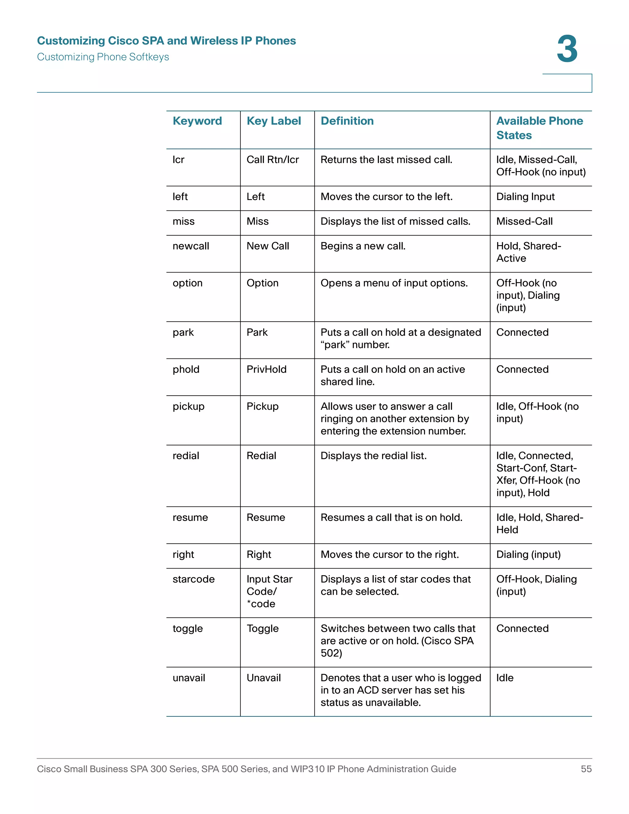
The table below lists each softkey and the phone state under which the softkey
displays. You can have a maximum of 16 softkeys for each call state field.
Cisco Small Business SPA 300 Series, SPA 500 Series, and WIP310 IP Phone Administration Guide 52](https://image.slidesharecdn.com/ciscospa303-administrationguide-141015151631-conversion-gate02/75/Cisco-spa303-administration-guide-64-2048.jpg)
![Customizing Cisco SPA and Wireless IP Phones
Configuring Ring Tones
3
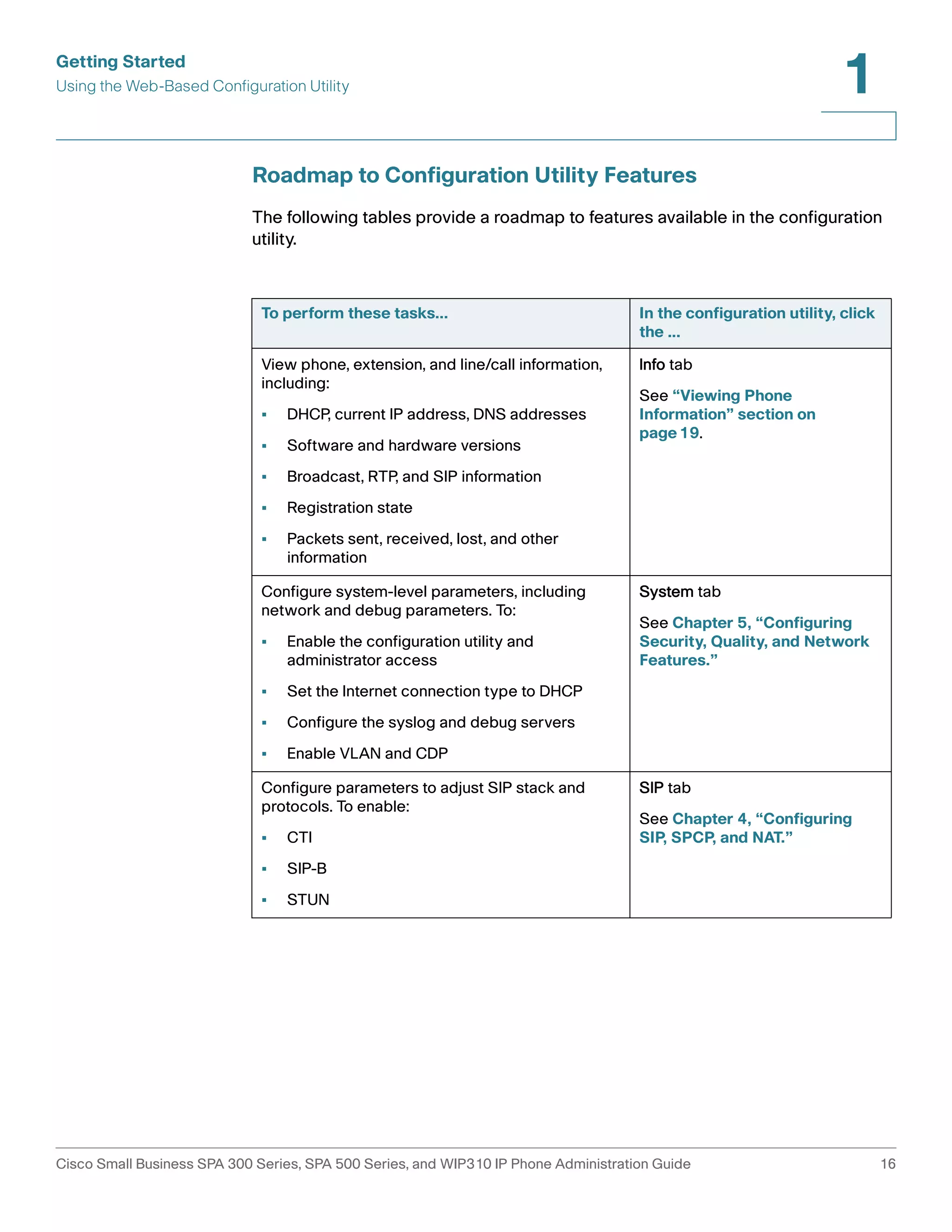
STEP 1 Log in to the configuration utility.
STEP 2 Click Admin Login and advanced.
STEP 3 Click the Ext <number> tab.
STEP 4 Under Call Feature Settings, in the Message Waiting field, choose yes.
STEP 5 Click Submit All Changes.
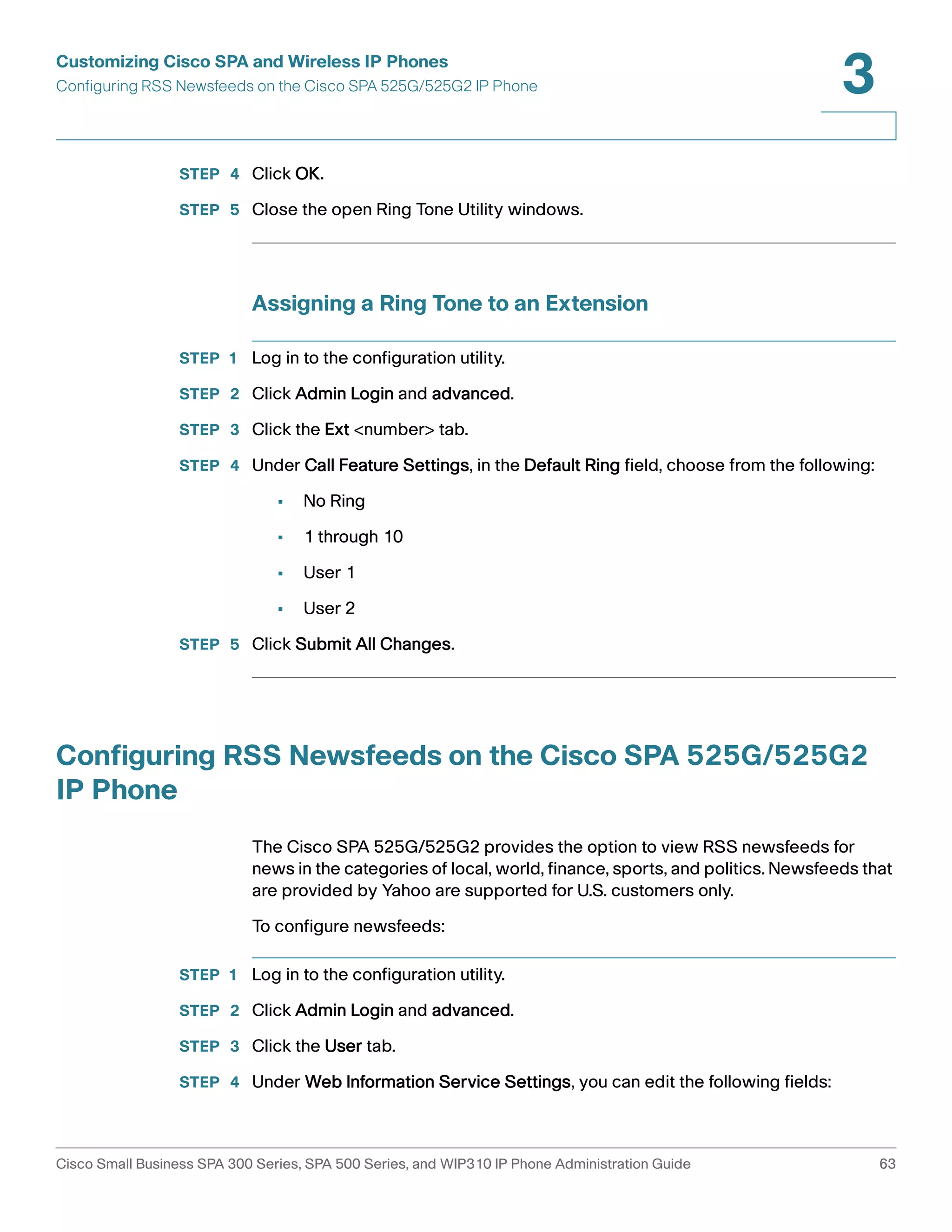
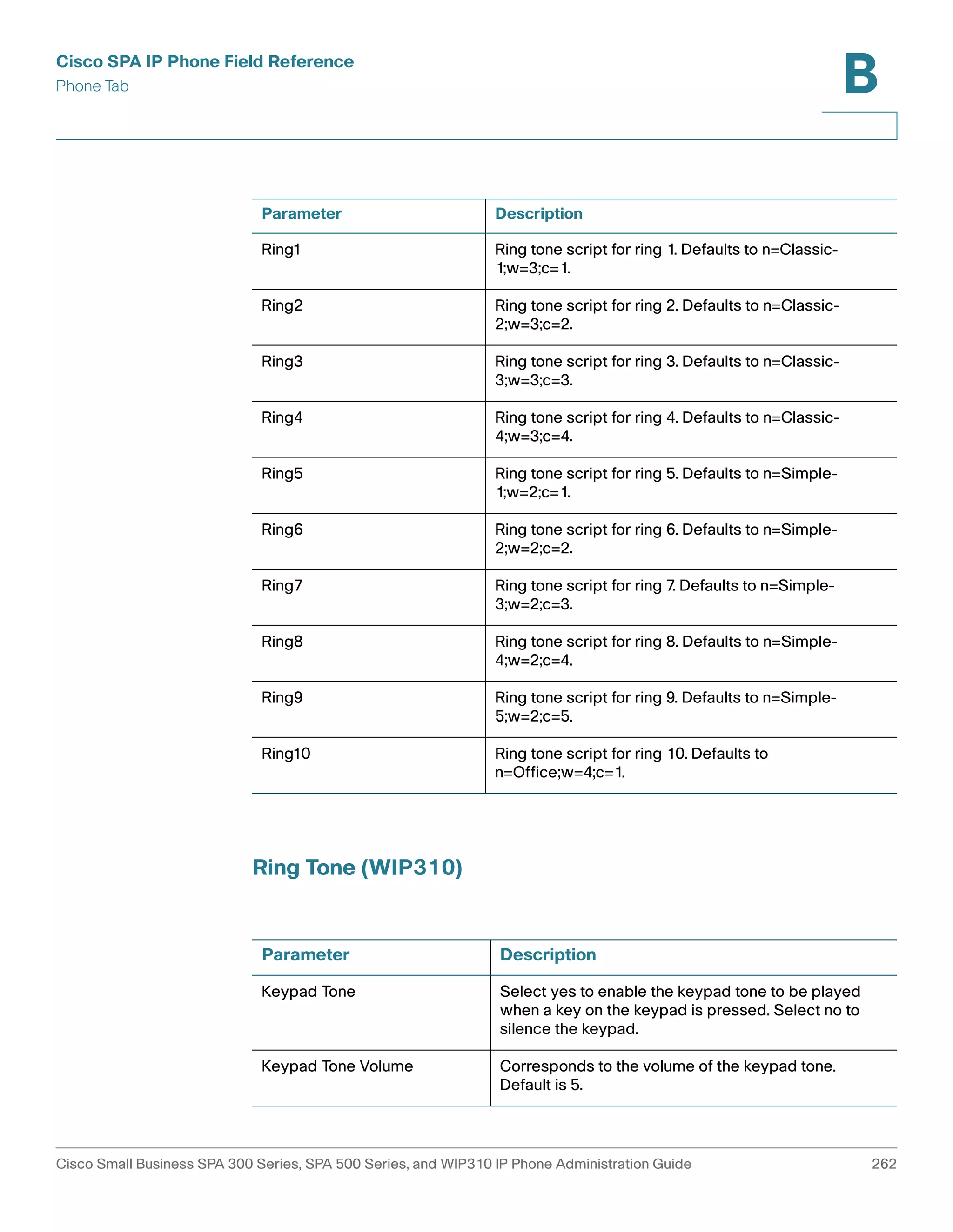
Configuring Ring Tones
You can define up to ten ring tones for a Cisco SPA 300 Series or Cisco SPA 500
Series IP Phone.
NOTE WIP310 ring tones are not configurable from the configuration utility.
You can define:
• The default ring tone for the extension
• Specific ring tones assigned to individual callers in the personal directory.
These override the default ring tone.
To configure ring tones:
STEP 1 Log in to the configuration utility.
STEP 2 Click Admin Login and advanced.
STEP 3 Click the Phone tab and proceed to the Ring Tone section.
You can configure the characteristics of each ring tone using a Ring Tone script. In
a Ring Tone script, you can assign a name for the ring tone, and specify:
• Name (n)—Ring tone name, such as Classic, Simple, and Office
• Waveform (w)—1, 2, 3, or 4
• Cadence (c)—1, 2, 3, 4, or 5
You can also download one of two available ring tones (user ring tone 1 or 2) using
TFTP:
http://phone_ip_addr/ringtone1?[url]
Cisco Small Business SPA 300 Series, SPA 500 Series, and WIP310 IP Phone Administration Guide 59](https://image.slidesharecdn.com/ciscospa303-administrationguide-141015151631-conversion-gate02/75/Cisco-spa303-administration-guide-71-2048.jpg)
![Customizing Cisco SPA and Wireless IP Phones
Configuring Ring Tones
3
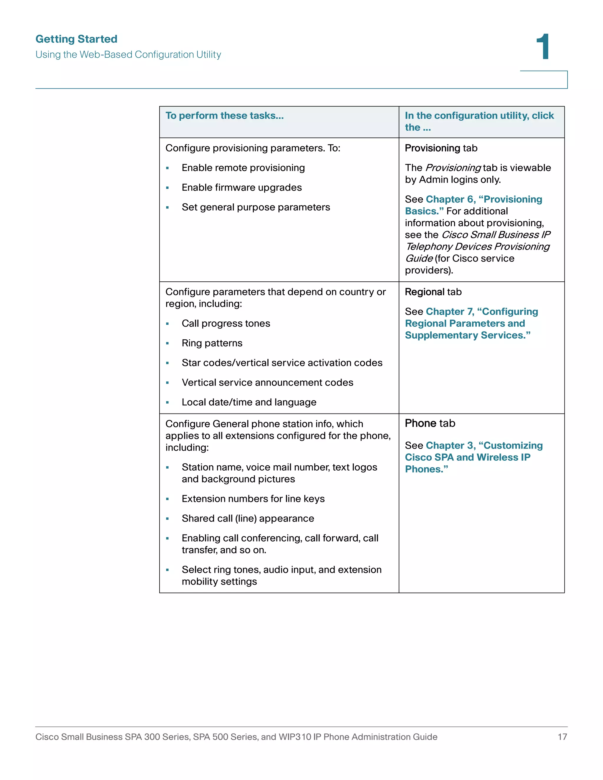
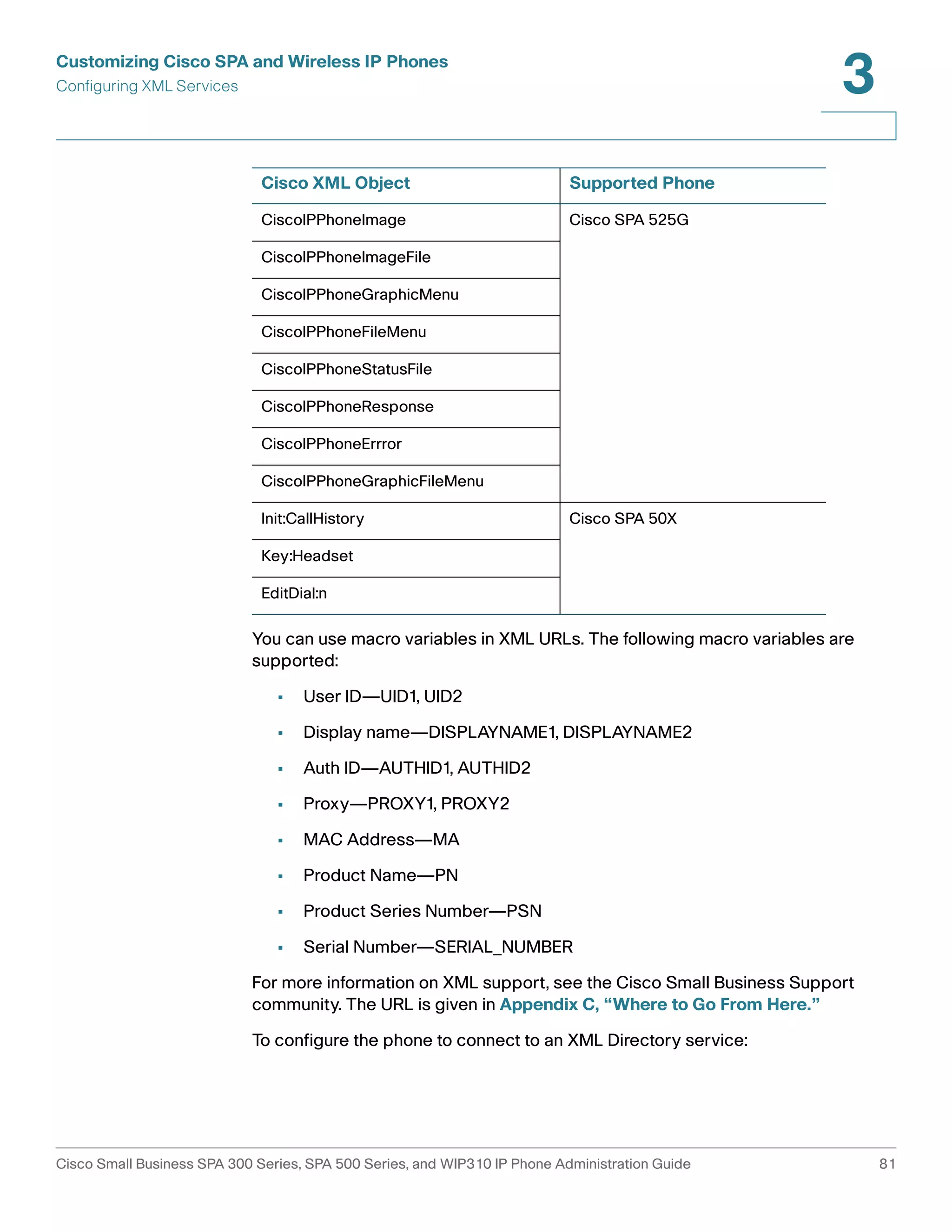
• Where the URL syntax is tftp://host[:port]/path.
• The default host is the TFTP host.
• Port is optional. The default port is 69.
• The link is case sensitive.
On the IP phones, user-downloaded ring tones are labeled User 1 and User 2 in
the choices for the Default Ring. On the phone ring tone menu, the User 1 and 2
choices are replaced by the corresponding name of the ring tone. “Not Installed”
appears if the user ring tone slots are not used.
For ring tone User 1 and User2, the cadence is fixed with the on-time equals to the
duration of the ring tone file and off-time equals to four seconds. The total ring
duration is fixed at 60 seconds. The user ring tone names displayed on the phone
LCD are derived from the ring tone file header file.
The phone does not require rebooting after downloading a ring tone.
To remove the User 1 ring tone from the phone, set the path to delete, as follows:
http://phone_ip_addr/ringtone1?/delete
STEP 4 Click Submit All Changes.
Configuring On-Demand Ring Tones (Cisco SPA 525G/
525G2)
The Cisco SPA 525G/525G2 supports on-demand ring tones, which means that
ring tones are downloaded and played from a TFTP server when a call comes in.
To configure:
STEP 1 Log in to the configuration utility.
STEP 2 Click Admin Login and advanced.
STEP 3 Click the Phone tab.
Cisco Small Business SPA 300 Series, SPA 500 Series, and WIP310 IP Phone Administration Guide 60](https://image.slidesharecdn.com/ciscospa303-administrationguide-141015151631-conversion-gate02/75/Cisco-spa303-administration-guide-72-2048.jpg)
![Customizing Cisco SPA and Wireless IP Phones
Configuring Ring Tones
3
STEP 4 Under Ring Tone, in one or more of the ten ring tone fields, enter the following:
n=office;w=[tftp://]host[:port]/path;c=0
and specify the URL to download in the host/port/path field. If the connection
cannot be established, a default ring tone is played.
STEP 5 Click Submit All Changes.
User-Created MP3 Ring Tones (Cisco SPA 525G/525G2)
Cisco SPA 525G/525G2 users can create up to two ring tones from an MP3 audio
file stored on a USB memory device. For instructions, see the Cisco Small
Business SPA 525G/525G2 User Guide (SIP), located on Cisco.com. (See
Appendix C, “Where to Go From Here,” for the location of this document.)
Creating and Uploading Ring Tones Using the Ring Tone
Utility (Cisco SPA 30X and Cisco SPA 50XG only)
To convert a file for use as a ring tone, use the Ring Tone Utility, available at:
https://www.myciscocommunity.com/docs/DOC-6672
You must have a .wav file less than 8 seconds in length saved to your computer.
You can also use a sound editor to create the file with the following restrictions:
• 16-bit PCM mono
• 8000 samples per second
• less than 6000 ms in length
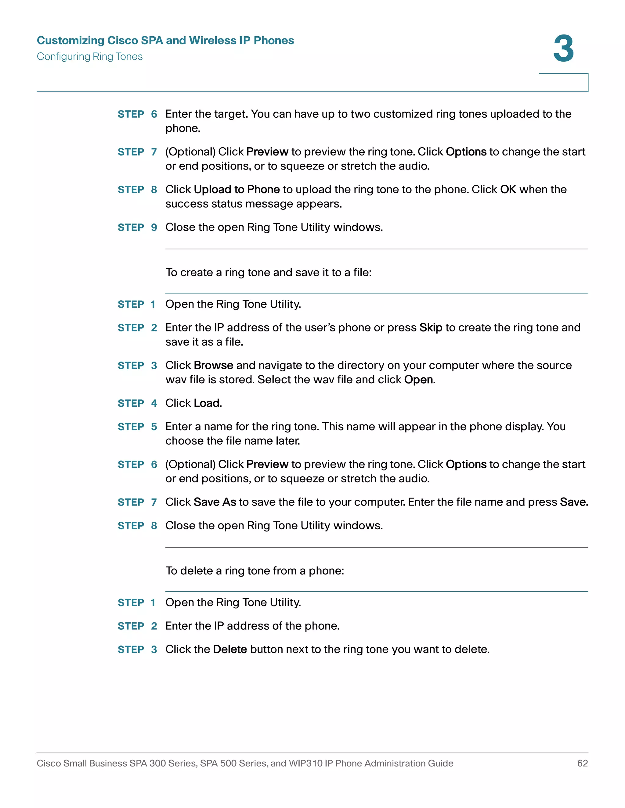
To create a ring tone and upload it to a phone:
STEP 1 Open the Ring Tone Utility.
STEP 2 Enter the IP address of the phone.
STEP 3 Click Browse and navigate to the directory on your computer where the source
.wav file is stored. Select the wav file and click Open.
STEP 4 Click Load Source File.
STEP 5 Enter a name for the ring tone. This name will appear in the display on the phone.
You choose the file name later.
Cisco Small Business SPA 300 Series, SPA 500 Series, and WIP310 IP Phone Administration Guide 61](https://image.slidesharecdn.com/ciscospa303-administrationguide-141015151631-conversion-gate02/75/Cisco-spa303-administration-guide-73-2048.jpg)
![Customizing Cisco SPA and Wireless IP Phones
Configuring Lightweight Directory Access Protocol (LDAP) for the Cisco SPA 300 Series and Cisco SPA
500 Series IP Phones
3
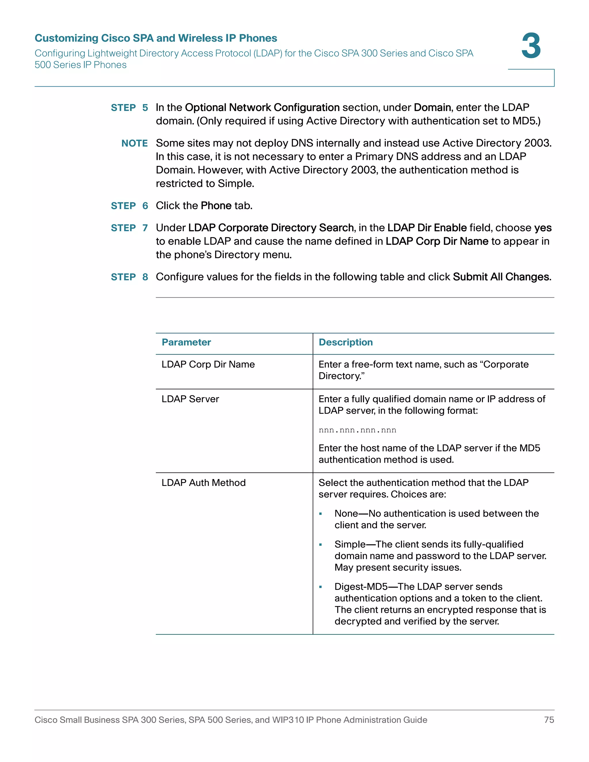
Parameter Description
LDAP Client DN Enter the distinguished name domain components
[dc] ; for example:
dc=cv2bu,dc=com
If using the default Active Directory schema
(Name(cn)->Users->Domain), an example of the
client DN follows:
cn="David Lee",dc=users,dc=cv2bu,dc=com
LDAP Username Enter the username for a credentialed user on the
LDAP server.
LDAP Password Enter the password for the LDAP username.
LDAP Search Base Specify a starting point in the directory tree from
which to search.
Separate domain components [dc] with a comma.
For example:
dc=cv2bu,dc=com
LDAP Last Name Filter This defines the search for surnames [sn], known as
last name in some parts of the world. For example,
sn:(sn=*$VALUE*). This search allows the provided
text to appear anywhere in a name, beginning,
middle, or end.
You must enter a value in both the last name and first
name fields so that the LDAP corporate directory
option displays on the phone. If both fields are
empty, the directory does not display.
LDAP First Name Filter This defines the search for the common name [cn].
For example, cn:(cn=*$VALUE*). This search allows
the provided text to appear anywhere in a name,
beginning, middle, or end.
You must enter a value in both the last name and first
name fields so that the LDAP corporate directory
option displays on the phone. If both fields are
empty, the directory does not display.
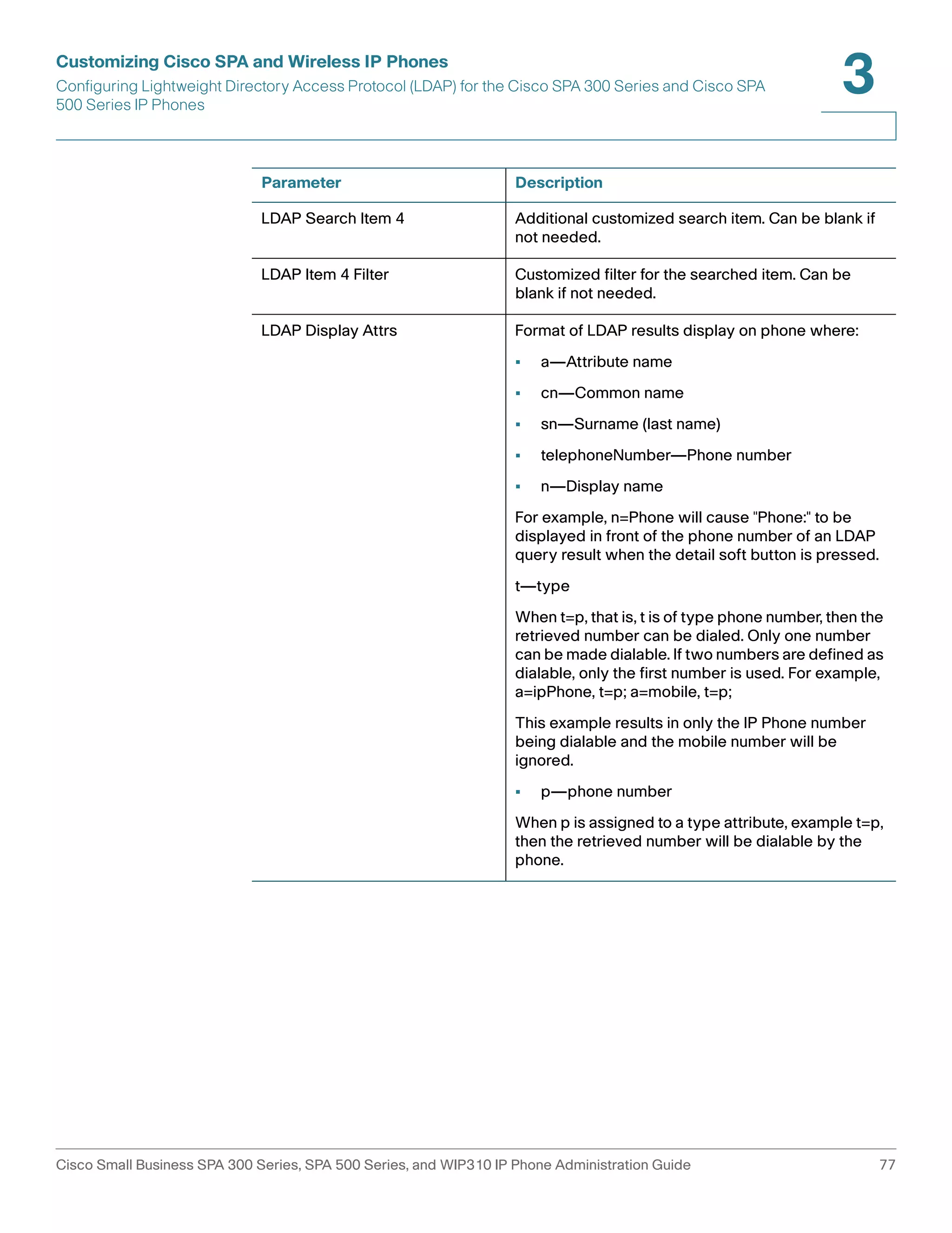
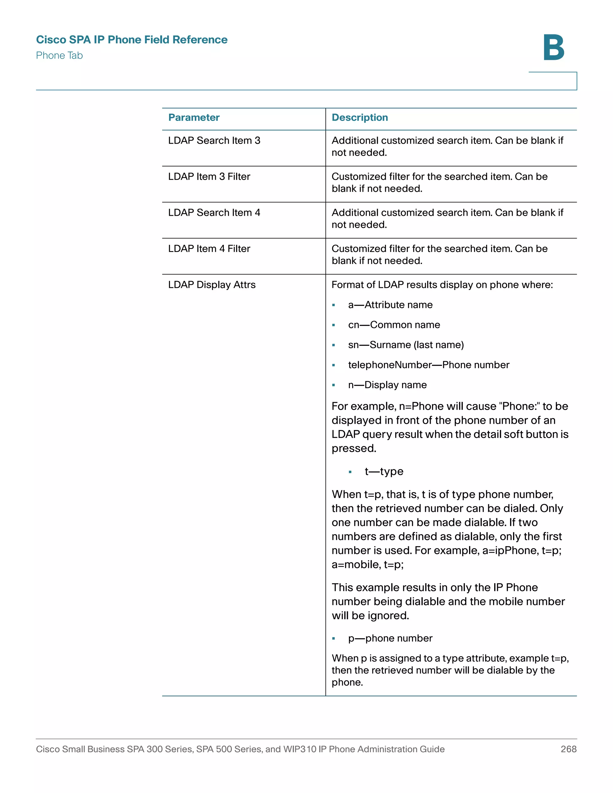
LDAP Search Item 3 Additional customized search item. Can be blank if
not needed.
LDAP Item 3 Filter Customized filter for the searched item. Can be
blank if not needed.
Cisco Small Business SPA 300 Series, SPA 500 Series, and WIP310 IP Phone Administration Guide 76](https://image.slidesharecdn.com/ciscospa303-administrationguide-141015151631-conversion-gate02/75/Cisco-spa303-administration-guide-88-2048.jpg)
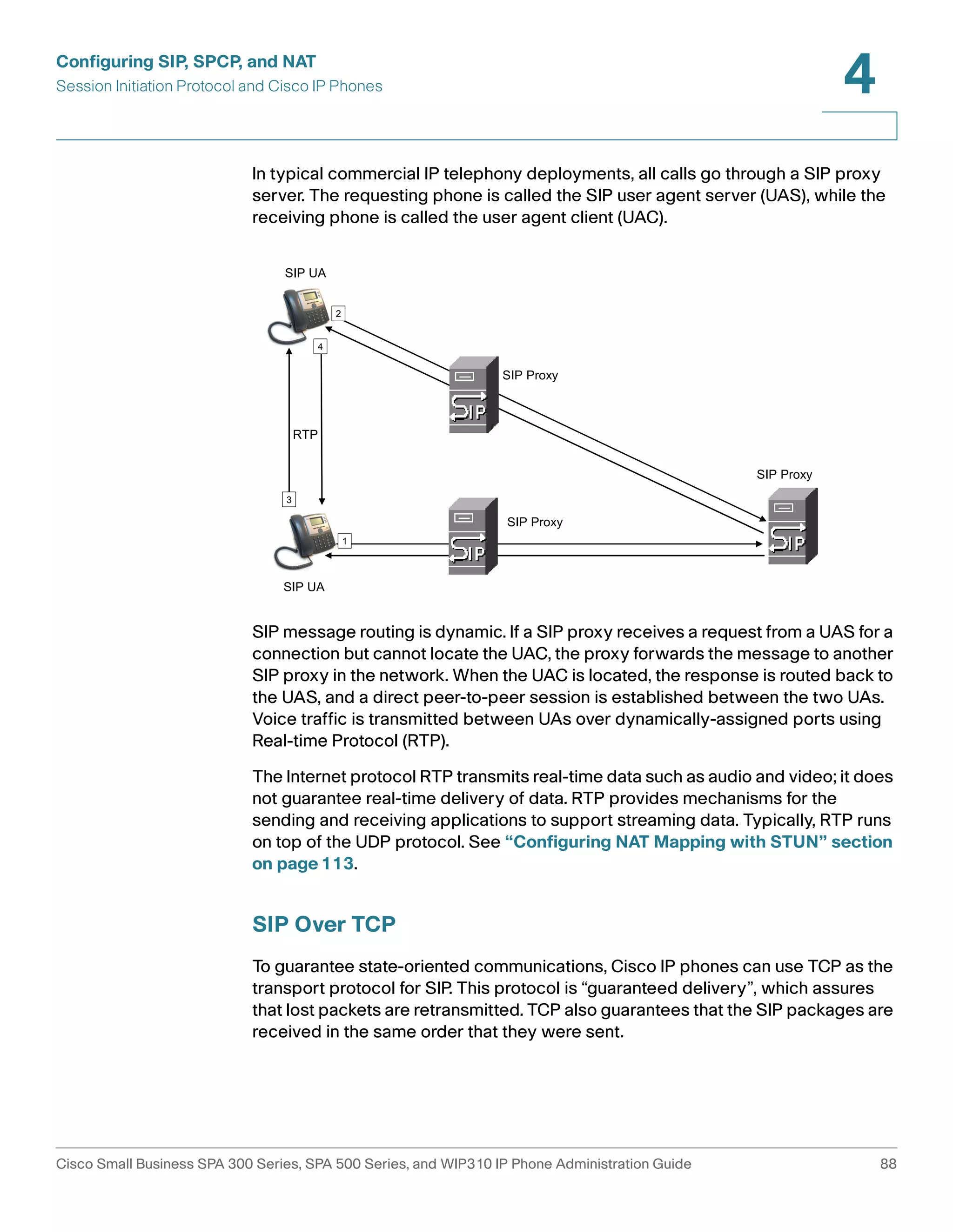
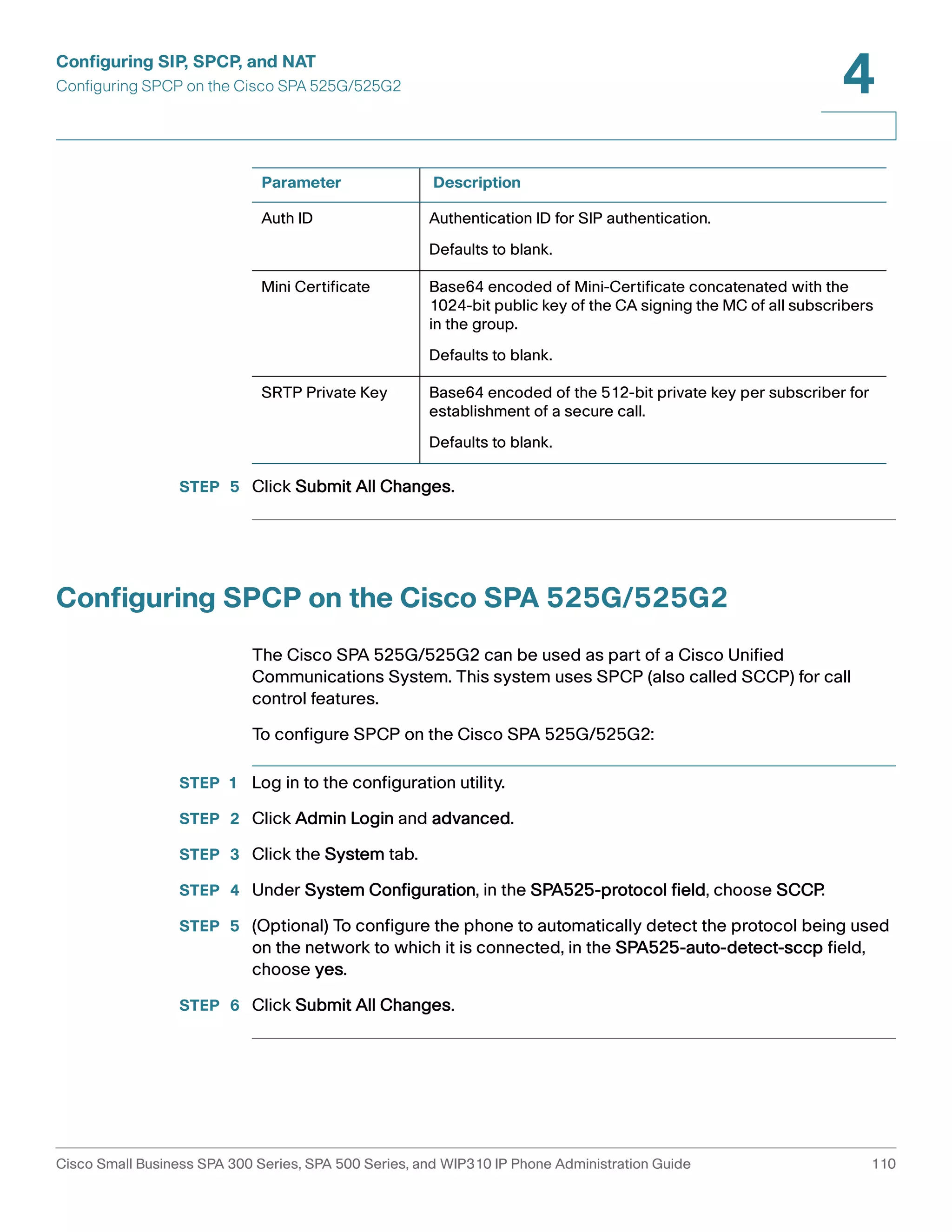
![Configuring SIP, SPCP, and NAT
Session Initiation Protocol and Cisco IP Phones
4
TCP overcomes the problem with UDP ports being blocked by corporate firewalls.
With TCP, new ports do not need to be opened or packets dropped, because TCP
is already in use for basic activities such as Internet browsing or e-commerce.
SIP Proxy Redundancy
An average SIP proxy server may handle tens of thousands of subscribers. A
backup server allows an active server to be temporarily switched out for
maintenance. Cisco phones support the use of backup SIP proxy servers to
minimize or eliminate service disruption.
A static list of proxy servers is not always adequate. If your user agents are served
by different domains, for example, you would not want to configure a static list of
proxy servers for each domain into every Cisco IP phone.
A simple way to support proxy redundancy is to configure a SIP proxy server in
the Cisco IP phone configuration profile. The DNS SRV records instruct the phones
to contact a SIP proxy server in a domain named in SIP messages. The phone
consults the DNS server. If configured, the DNS server returns an SRV record that
contains a list of SIP proxy servers for the domain, with their host names, priority,
listening ports, and so on. The Cisco IP phone tries to contact the hosts in the order
of their priority.
If the Cisco IP phone currently uses a lower-priority proxy server, the phone
periodically probes the higher-priority proxy and switches to the higher-priority
proxy when available.
Configuring Survivable Remote Site Telephony (SRST) Support
The proxy and outbound proxy fields in the Ext tab can be configured with an
extension that includes a statically-configured DNS SRV record or DNS A record.
This allows for failover and fallback functionality with a secondary proxy server.
The format for the parameter value is as follows:
FQDN format: hostname[:port][:SRV=host-list OR :A=ip-list]
host-list: srv[|srv[|srv…]]
srv: hostname[:port][:p=priority][:weight][:A=ip-list]
ip-list: ip-addr[,ip-addr[,ip-addr…]]
The default priority is 0 and default weight is 1. The default port is 0, and the
application substitutes the proper port value (for example, port 5060 for SIP).
Cisco Small Business SPA 300 Series, SPA 500 Series, and WIP310 IP Phone Administration Guide 89](https://image.slidesharecdn.com/ciscospa303-administrationguide-141015151631-conversion-gate02/75/Cisco-spa303-administration-guide-101-2048.jpg)
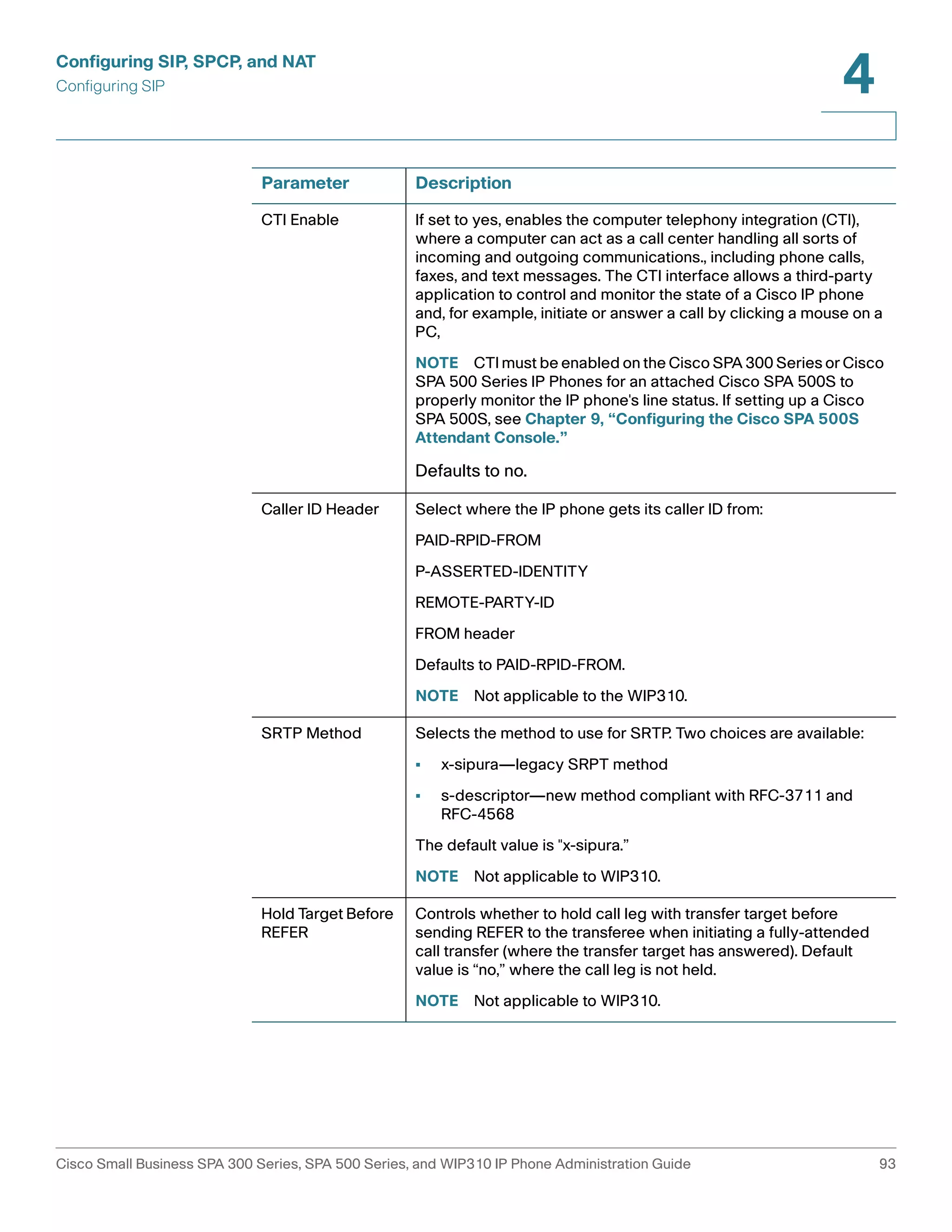
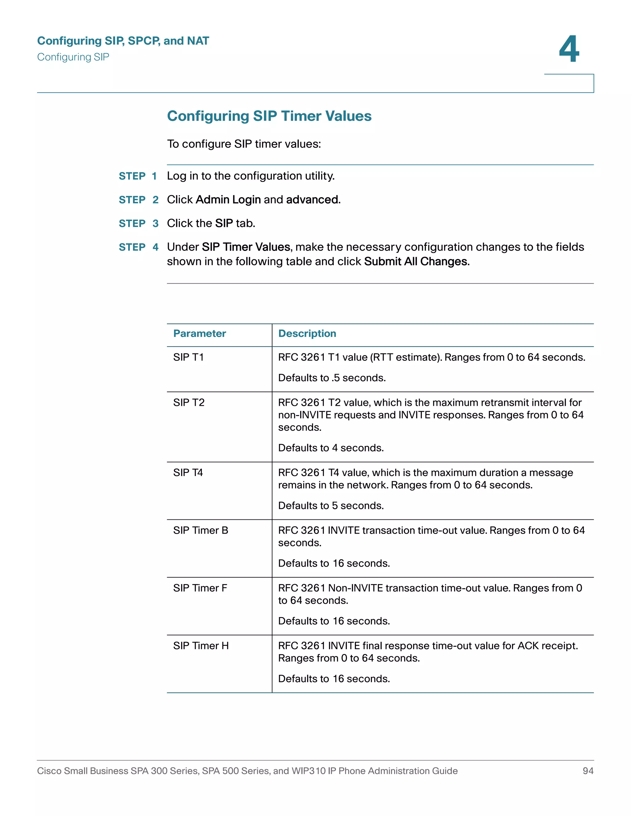
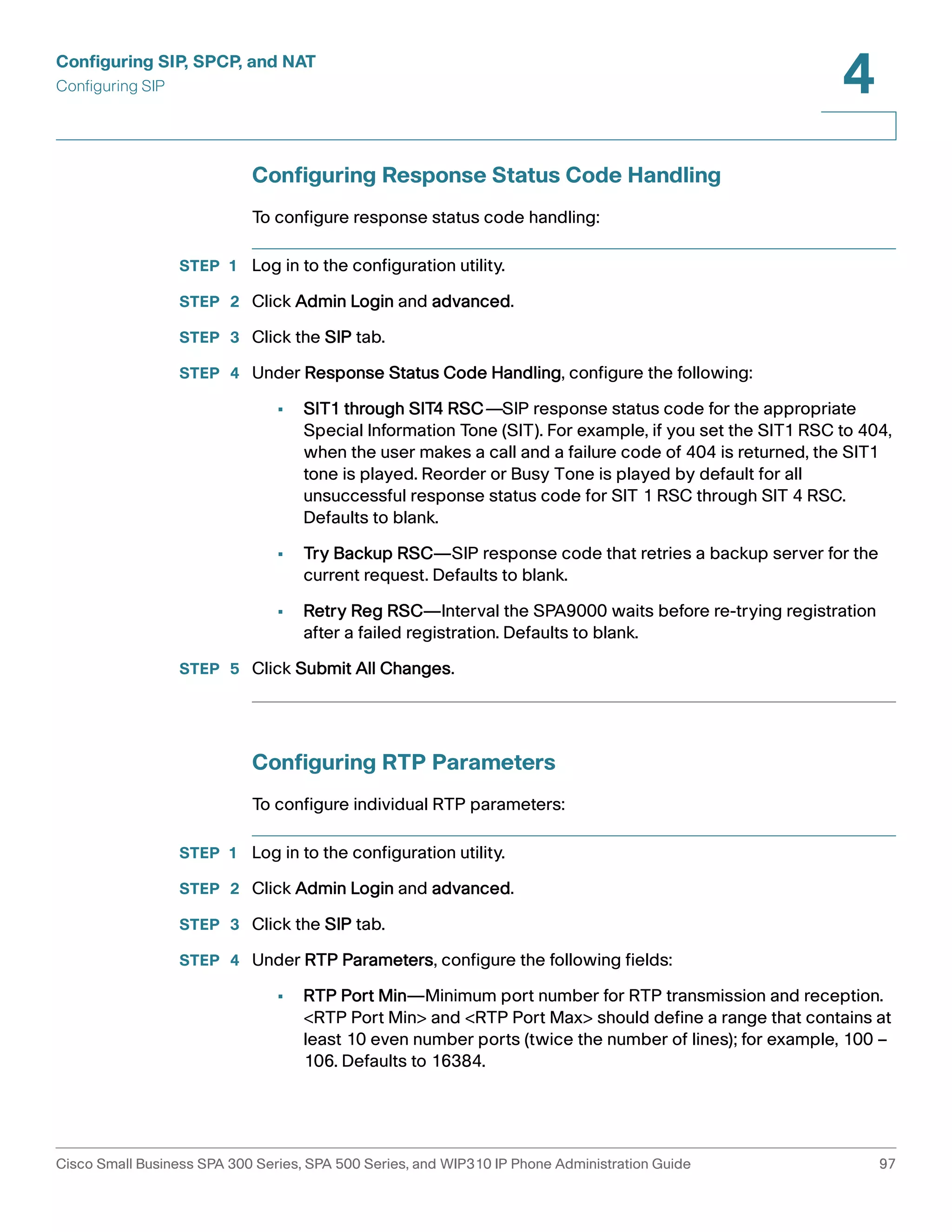
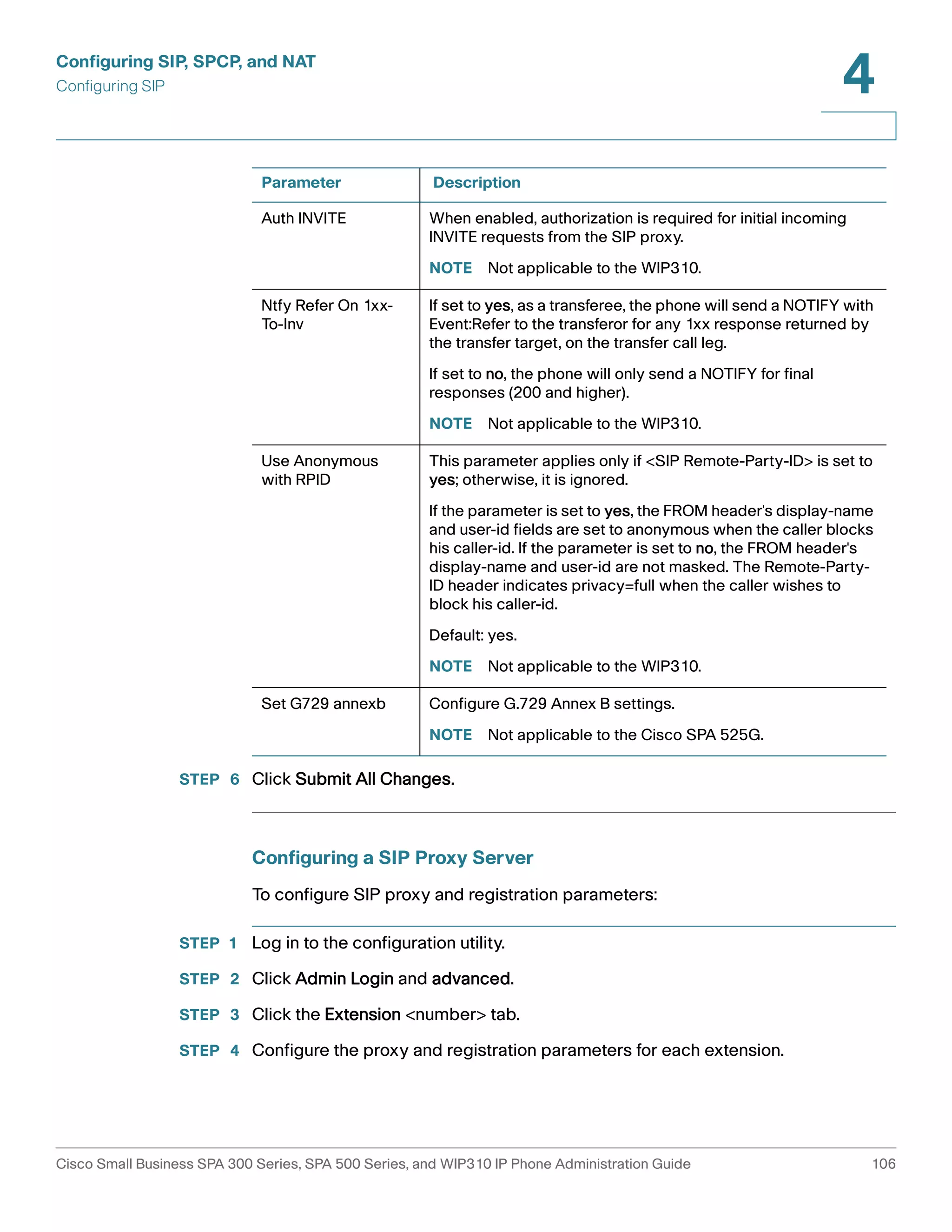
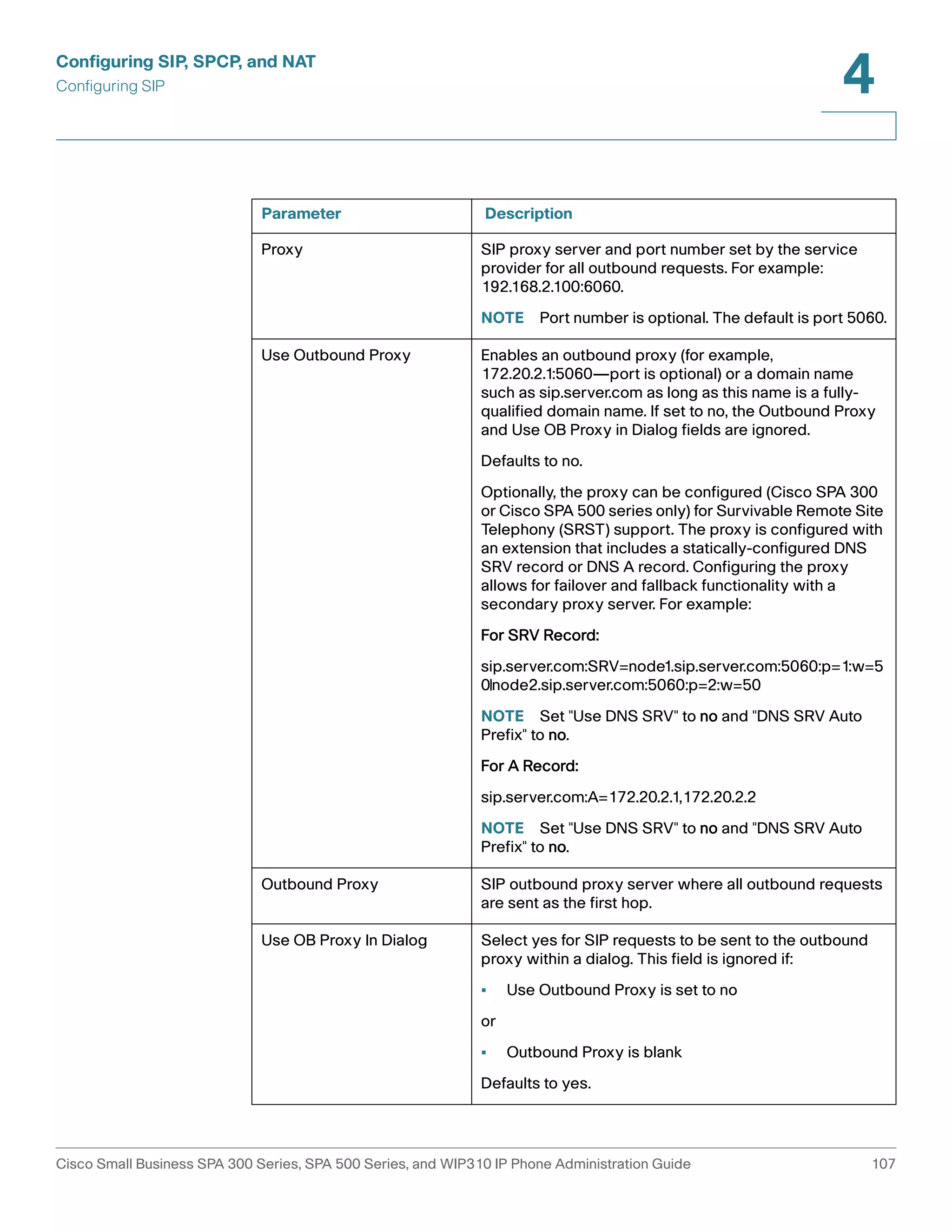
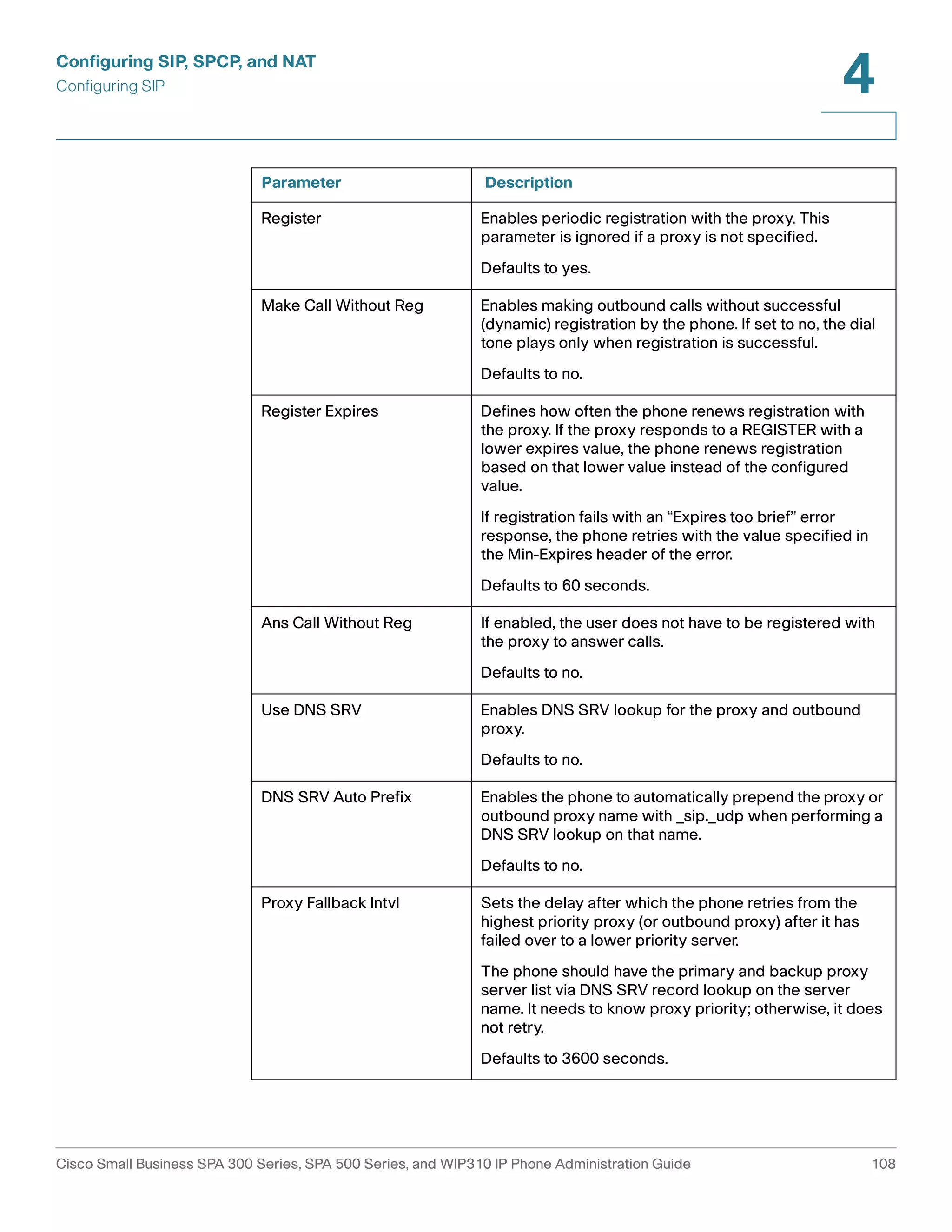
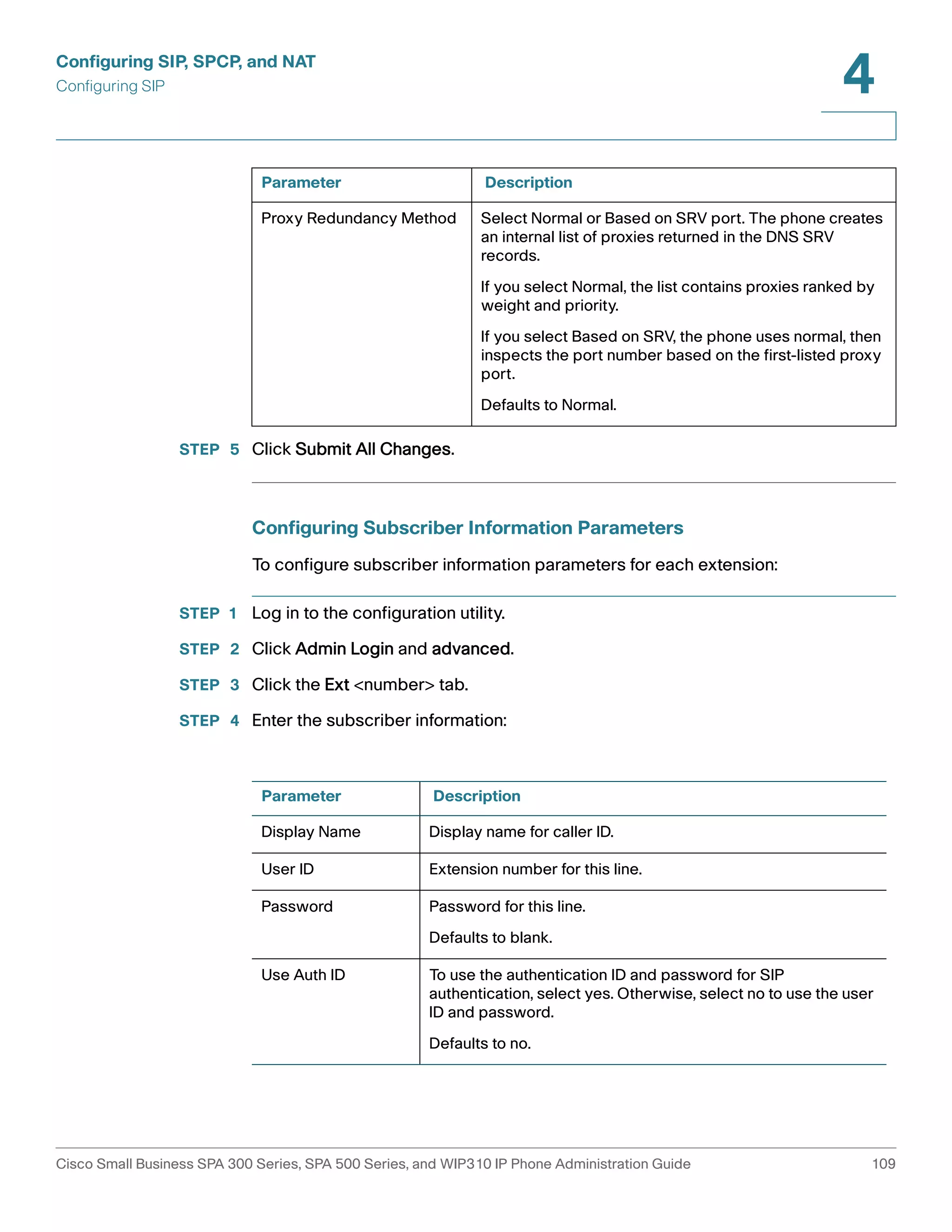
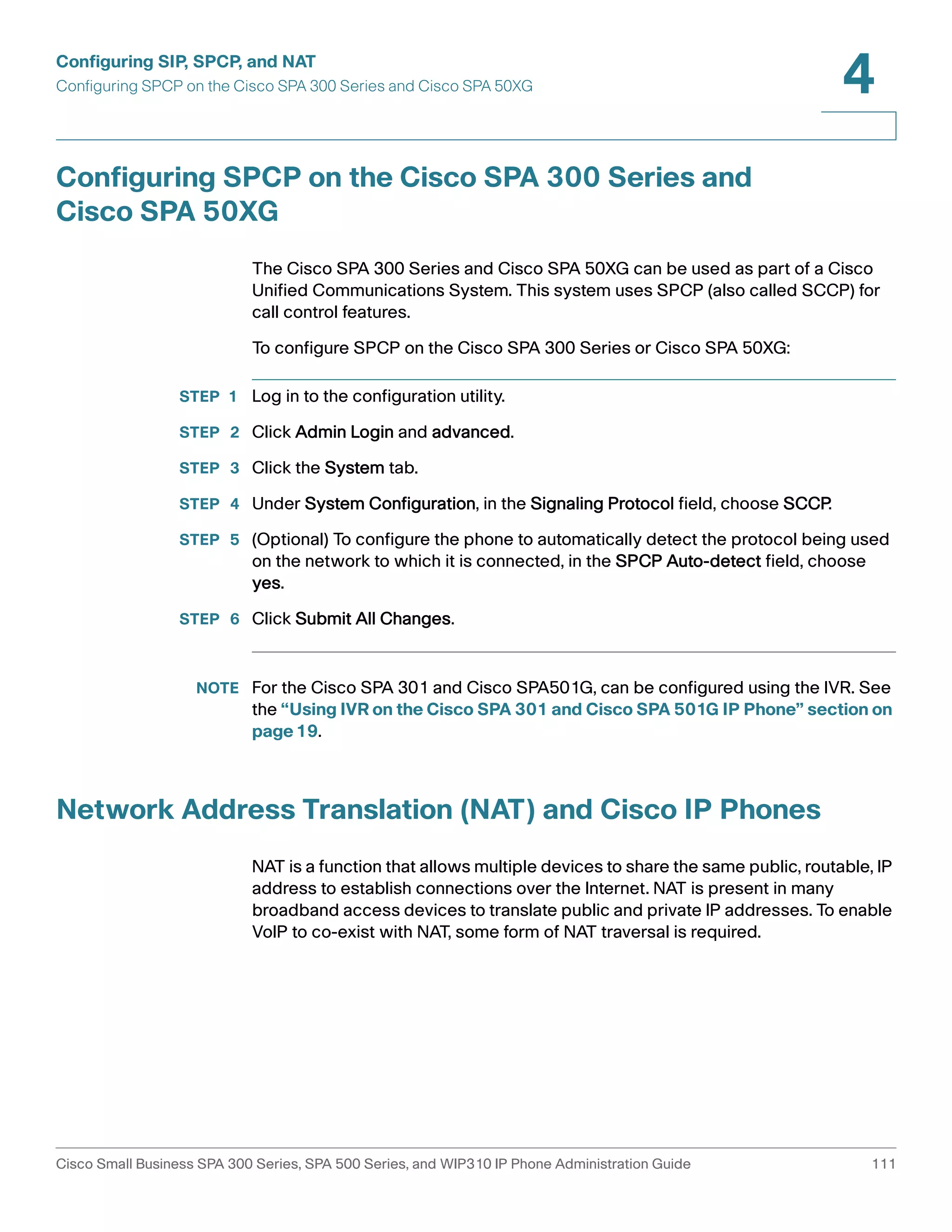
![Configuring SIP, SPCP, and NAT
Configuring SIP
4
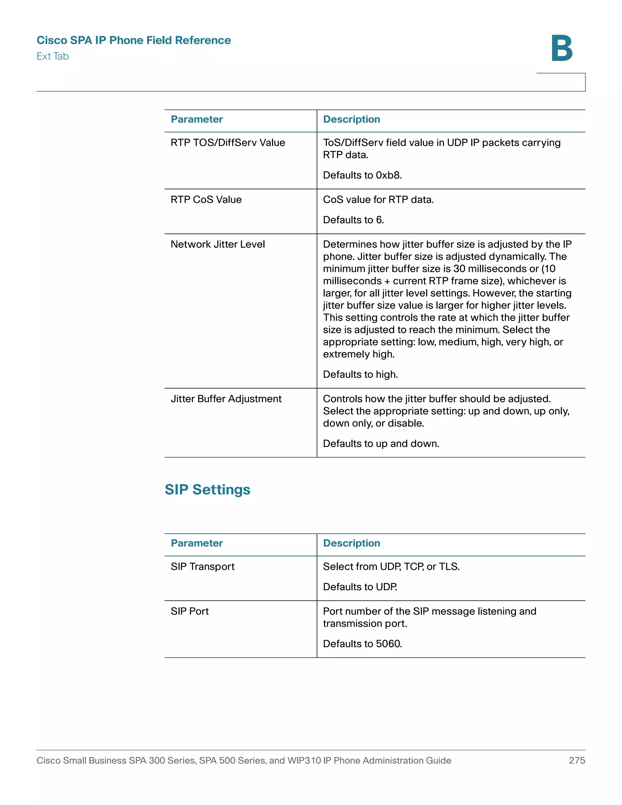
Configuring SIP Settings for Extensions
STEP 1 Log in to the configuration utility.
STEP 2 Click Admin Login and advanced.
STEP 3 Click the Extension <number> tab.
STEP 4 Under Network Settings, configure the following fields:
Parameter Description
SIP ToS/DiffServ
Value
Time of service (ToS)/differentiated services (DiffServ) field
value in UDP IP packets carrying a SIP message.
Defaults to 0x68.
SIP CoS Value [0-7] Class of service (CoS) value for SIP messages.
Defaults to 3.
RTP ToS/DiffServ
Value
ToS/DiffServ field value in UDP IP packets carrying RTP data.
Defaults to 0xb8.
RTP CoS Value [0-7] CoS value for RTP data.
Defaults to 6.
Network Jitter Level Determines how jitter buffer size is adjusted by the SPA9000.
Jitter buffer size is adjusted dynamically. The minimum jitter
buffer size is 30 milliseconds or (10 milliseconds + current RTP
frame size), whichever is larger, for all jitter level settings.
However, the starting jitter buffer size value is larger for higher
jitter levels. This setting controls the rate at which the jitter
buffer size is adjusted to reach the minimum. Select the
appropriate setting: low, medium, high, very high, or extremely
high.
Defaults to high.
Jitter Buffer
Adjustment
Controls how the jitter buffer should be adjusted. Select the
appropriate setting: up and down, up only, down only, or
disable.
Defaults to up and down.
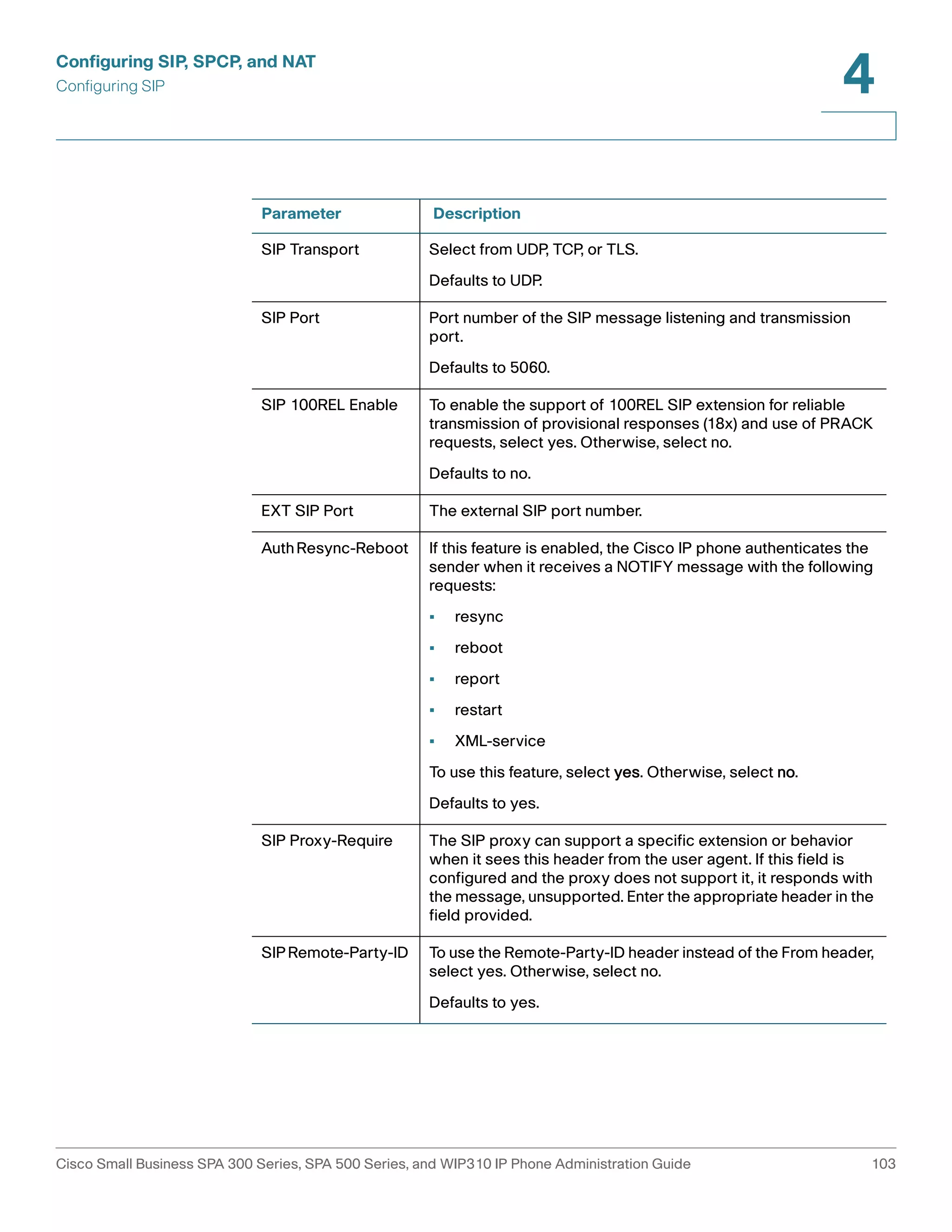
STEP 5 Under SIP Settings, configure the following fields:
Cisco Small Business SPA 300 Series, SPA 500 Series, and WIP310 IP Phone Administration Guide 102](https://image.slidesharecdn.com/ciscospa303-administrationguide-141015151631-conversion-gate02/75/Cisco-spa303-administration-guide-114-2048.jpg)
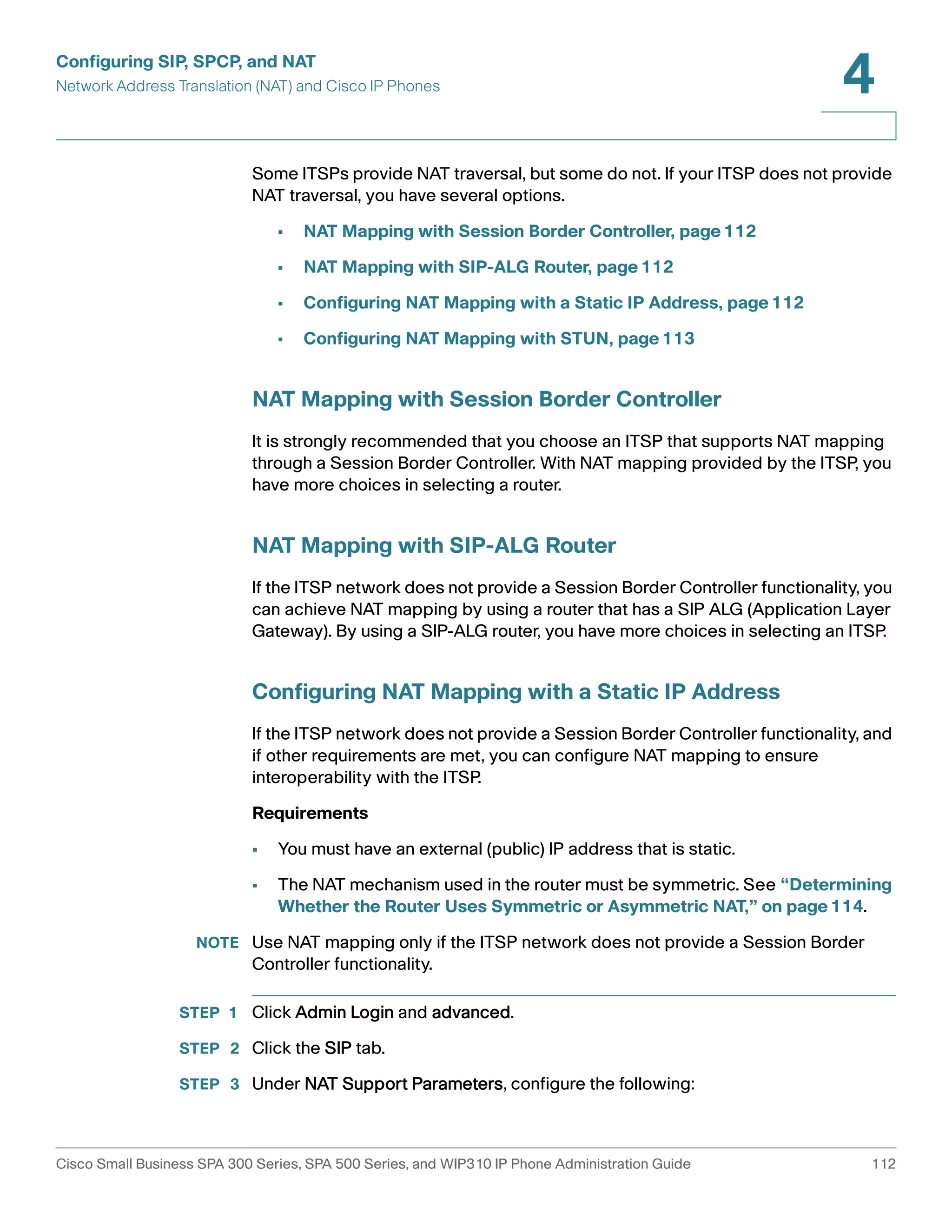

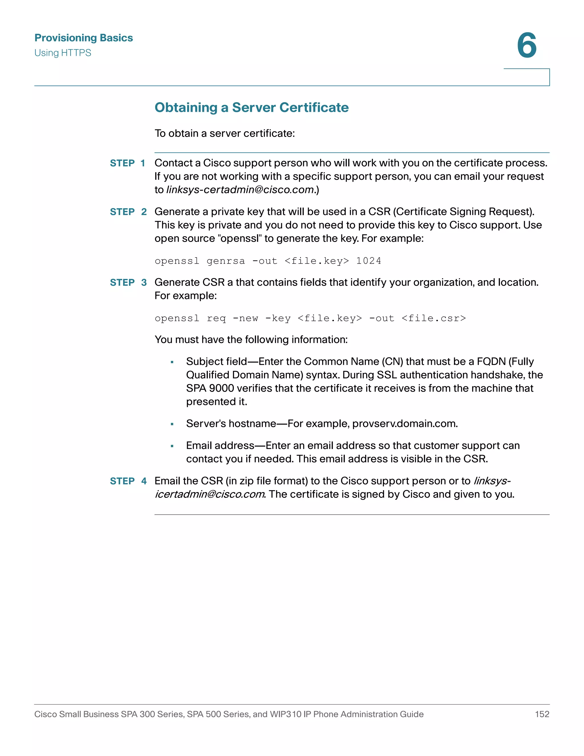
![Provisioning Basics
Provisioning Capabilities
6
To provision from the phone:
Cisco SPA 303 and Cisco SPA 50XG:
STEP 1 Press Setup, then scroll to Profile Rule.
STEP 2 Enter the profile rule using the following format, then press the Resync soft button.
protocol://server[:port]/profile_pathname
For example:
tftp://192.168.1.5/spa504.cfg
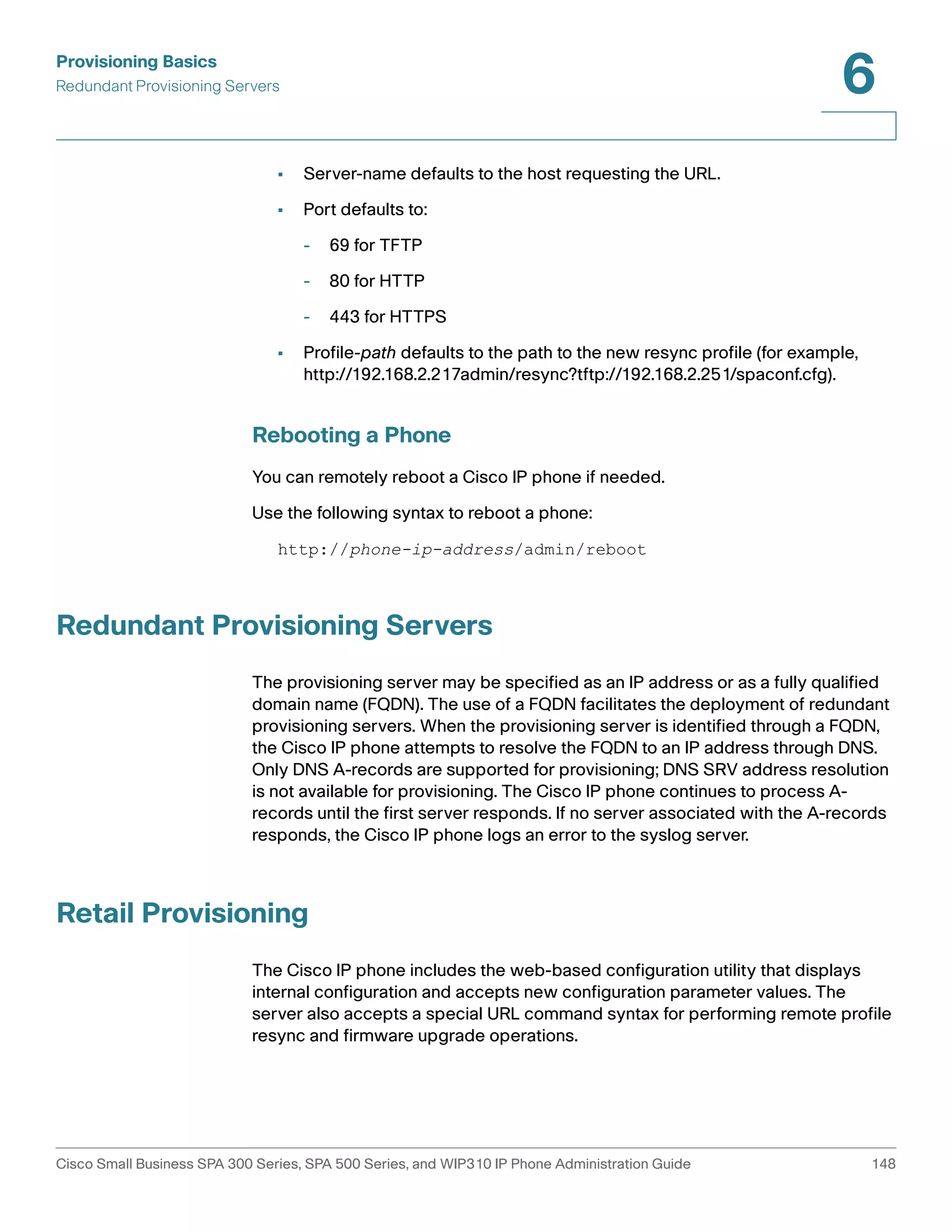
If no protocol is specified, TFTP is assumed. If no server-name is specified, the
host that requests the URL is used as server-name.
If no port is specified, the default port is used (69 for TFTP, 80 for HTTP, and 443
for HTTPS). then the address can be entered in and press Resync.
The status of the remote customization process is shown by the phone’s mute
button blinking in the following patterns:
• Red/orange slow blink (1.0 seconds on, 1.0 seconds off): Contacting server,
server not resolvable, not reachable, or down
• Red/orange slow blink (0.2 seconds on, 0.2 seconds off, 0.2 seconds on, 1.4
seconds off): Server responded with file not found or corrupt file
WIP310
STEP 1 Press the Select button to choose Settings and press the Select button again.
STEP 2 Navigate to Misc Settings.
STEP 3 Navigate to profile rule. Enter the profile rule in the following format:
protocol://server[:port]/profile_pathname
For example, to have the WIP310 provisioning done by the Cisco SPA 9000
Voice System, enter:
192.168.2.64/cfg/generic.xml
Cisco Small Business SPA 300 Series, SPA 500 Series, and WIP310 IP Phone Administration Guide 141](https://image.slidesharecdn.com/ciscospa303-administrationguide-141015151631-conversion-gate02/75/Cisco-spa303-administration-guide-153-2048.jpg)
![Provisioning Basics
IP Phone Configuration Profiles
6
SPA 525G/525G2
STEP 1 Press the Setup button.
STEP 2 Scroll to Device Administration and press Select.
STEP 3 Scroll to Profile Rule and press Select.
STEP 4 Enter the profile rule using the following format, then press the Resync soft button.
protocol://server[:port]/profile_pathname
For example:
tftp://192.168.1.5/spa525.cfg
IP Phone Configuration Profiles
The IP phone configuration profile defines the parameter values for a specific
device. The configuration profile can be used in two formats:
• Open (XML-style) format
• Proprietary, plain-text format
The XML-style format lets you use standard tools to compile the parameters and
values. To protect confidential information contained in the configuration profile,
this type of file is generally delivered from the provisioning server to the IP phone
over a secure channel provided by HTTPS.
The XML file consists of a series of elements (one per configuration parameter),
encapsulated within the element tags <flat-profile> … </flat-profile>. The
encapsulated elements specify values for individual parameters. The following is
an example of a valid XML profile:
<flat-profile>
<Admin_Passwd>some secret</Admin_Passwd>
<Upgrade_Enable>Yes</Upgrade_Enable>
</flat-profile>
Cisco Small Business SPA 300 Series, SPA 500 Series, and WIP310 IP Phone Administration Guide 142](https://image.slidesharecdn.com/ciscospa303-administrationguide-141015151631-conversion-gate02/75/Cisco-spa303-administration-guide-154-2048.jpg)
![Provisioning Basics
IP Phone Configuration Profiles
6
The names of parameters in XML profiles can generally be inferred from the Cisco
IP phones configuration web pages, by substituting underscores (_) for spaces
and other control characters. Further, to distinguish between Lines 1, 2, 3, and 4,
corresponding parameter names are augmented by the strings _1_, _2_, _3_, and
_4_. For example, Line 1 Proxy is named Proxy_1_ in XML profiles.
The plain-text configuration file uses a proprietary format, which can be encrypted
to prevent unauthorized use of confidential information. By convention, the profile
is named with the extension .cfg (for example, spa504.cfg). The Cisco SIP Profile
Compiler (SPC) tool is provided for compiling the plain-text file containing
parameter-value pairs into an encrypted CFG file. The SPC tool is available from
Cisco for the Win32 environment (spc.exe) and Linux-i386-elf environment (spc-linux-
i386-static). Availability of the SPC tool for the OpenBSD environment is
available on a case-by-case basis.
The syntax of the plain-text file accepted by the profile compiler is a series of
parameter-value pairs, with the value in double quotes. Each parameter-value pair
is followed by a semicolon. The following is an example of a valid text source
profile for input to the SPC tool:
Admin_Passwd “some secret”;
Upgrade_Enable “Yes”;
Parameters in the case of source text files for the SPC tool are similarly named,
except that to differentiate Line 1, 2, 3, and 4, the appended strings ([1], [2], [3], or
[4]) are used. For example, the Line 1 Proxy is named Proxy[1] in source text
profiles for input to the SPC.
Obtaining the SPC Tool
The SPC tool is available on cisco.com. To obtain the software:
STEP 1 Go to:
http://tools.cisco.com/support/downloads/go/Redirect.x?mdfid=282414147
STEP 2 Click the Profile Compiler (SPC) Tool link.
STEP 3 Choose the version of software that is installed on the phones.
STEP 4 Follow the links to download the software.
Cisco Small Business SPA 300 Series, SPA 500 Series, and WIP310 IP Phone Administration Guide 143](https://image.slidesharecdn.com/ciscospa303-administrationguide-141015151631-conversion-gate02/75/Cisco-spa303-administration-guide-155-2048.jpg)
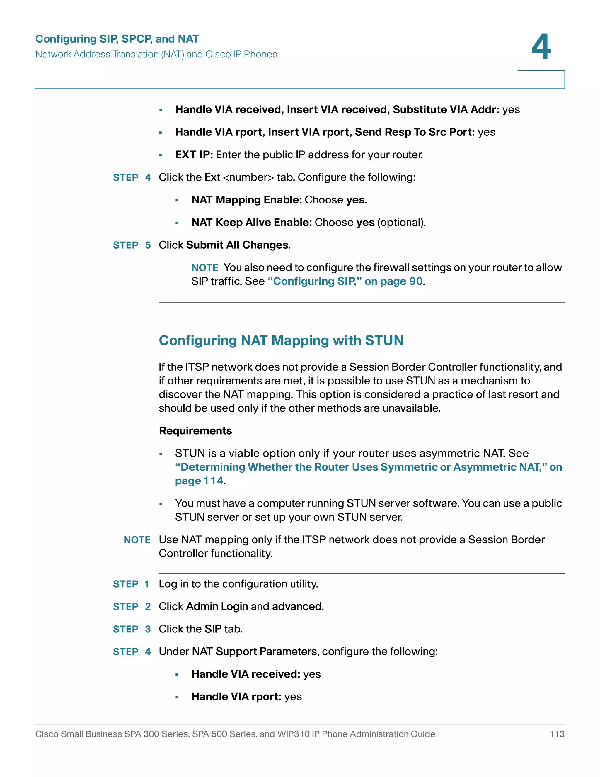
![Provisioning Basics
Upgrading, Resyncing, and Rebooting Phones
6
Enter the upgrade command into your browser’s address bar to upgrade firmware
on a phone. Use the following syntax:
http://phone-ip-address/admin/upgrade?protocol://server-name[:
port]]/firmware-path
• Protocol defaults to TFTP.
• Server name is the host requesting the URL.
• Port is the port of the protocol being used (for example, 69 for TFTP or 80
for HTTP).
• Firmware-path defaults to /spa.bin (for example, http://192.168.2.217/
admin/upgrade?tftp://192.168.2.251/spa.bin) for SPA phones and /
wip310.img for the WIP310. The firmware-pathname is typically the file
name of the binary located in a directory on the TFTP or HTTP server.
Firmware Upgrade Parameters
The following table defines the function and usage of each parameter in the
Firmware Upgrade section of the Provisioning tab.
Parameter Description
Upgrade_Enable Enables firmware upgrade operations independently
of resync actions.
Defaults to Yes.
Upgrade_Error_Retry_Delay The upgrade retry interval (in seconds) applied in
case of upgrade failure. The device has a firmware
upgrade error timer that activates after a failed
firmware upgrade attempt. The timer is initialized with
the value in this parameter. The next firmware upgrade
attempt occurs when this timer counts down to zero.
The default is 3600 seconds.
Downgrade_Rev_Limit Enforces a lower limit on the acceptable version
number during a firmware upgrade or downgrade.
The device does not complete a firmware upgrade
operation unless the firmware version is greater than
or equal to this parameter.
The default is (empty).
Cisco Small Business SPA 300 Series, SPA 500 Series, and WIP310 IP Phone Administration Guide 146](https://image.slidesharecdn.com/ciscospa303-administrationguide-141015151631-conversion-gate02/75/Cisco-spa303-administration-guide-158-2048.jpg)
![Provisioning Basics
Upgrading, Resyncing, and Rebooting Phones
6
Parameter Description
Upgrade_Rule This parameter is a firmware upgrade script with the
Log_Upgrade_Request_Msg Syslog message issued at the start of a firmware
Log_Upgrade_Success_Msg Syslog message issued after a firmware upgrade
Log_Upgrade_Failure_Msg Syslog message issued after a failed firmware
License Keys This field is empty.
Resyncing a Phone
same syntax as Profile_Rule. Defines upgrade
conditions and associated firmware URLs.
The default is (empty).
upgrade attempt.
The default is
$PN $MAC -- Requesting upgrade $SCHEME://
$SERVIP:$PORT$PATH
attempt completes successfully.
The default is
$PN $MAC -- Successful upgrade $SCHEME://
$SERVIP:$PORT$PATH -- $ERR
upgrade attempt.
The default is
$PN $MAC -- Upgrade failed: $ERR.
You can resync an IP phone to a specific remote profile. The configuration of the
phone you resync will match the configuration of the remote phone. The phone
can be configured to resync its internal configuration state to a remote profile
periodically and on power up.
NOTE The phone resyncs only when it is idle.
Use the following syntax to resync a phone’s profile to a profile on a TFTP, HTTP, or
HTTPS server:
http://phone-ip-addr/admin/resync?protocol://server-name[:
port]/profile-pathname
• Parameter following resync? defaults to the Profile Rule setting on the web
server Provisioning page.
• Protocol defaults to TFTP.
Cisco Small Business SPA 300 Series, SPA 500 Series, and WIP310 IP Phone Administration Guide 147](https://image.slidesharecdn.com/ciscospa303-administrationguide-141015151631-conversion-gate02/75/Cisco-spa303-administration-guide-159-2048.jpg)
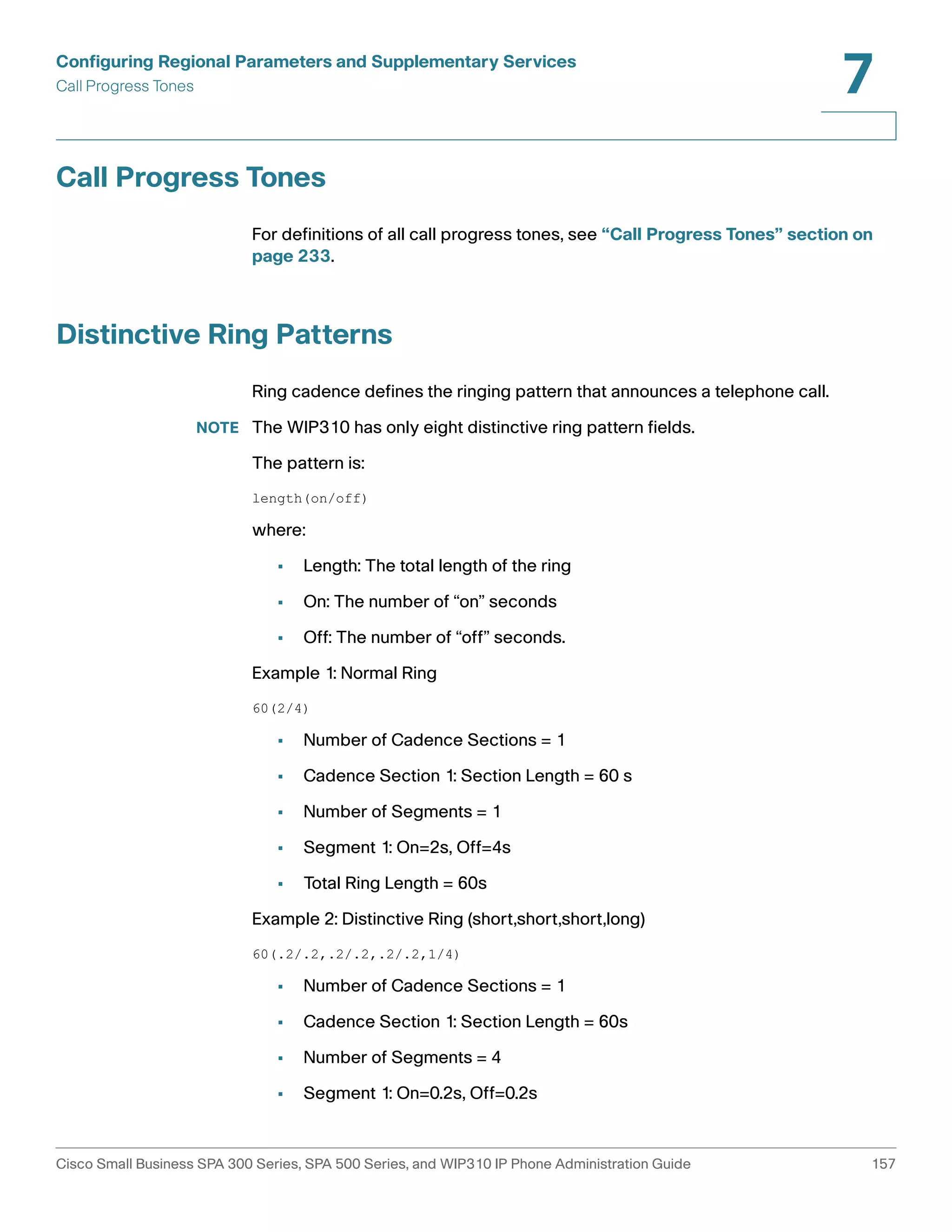
![Configuring Regional Parameters and Supplementary Services
Advanced Scripting for Cadences, Call Progress Tones, and Ring Tones
7
Advanced Scripting for Cadences, Call Progress Tones, and
Ring Tones
Advanced information on defining tones an and cadences follows.
A CadScript is a mini-script that specifies the cadence parameters of a signal. It
can be up to 127 characters. The syntax follows:
1[;S2]—where Si=Di(oni,1/offi,1[,oni,2/offi,2[,oni,3/offi,3[,oni,4/offi,4[,oni,5/
offi,5[,oni,6/offi,6]]]]]) and is known as a section, oni,j and offi,j are the on/off
duration in seconds of a segment and i = 1 or 2, and j = 1 to 6.
Di is the total duration of the section in seconds. All durations can have up to
3 decimal places to provide 1 ms resolution. The wildcard character “*”
stands for infinite duration. The segments within a section are played in
order and repeated until the total duration is played.
Example 1: Normal Ring
60(2/4)
Number of Cadence Sections = 1
Cadence Section 1: Section Length = 60 s
Number of Segments = 1
Segment 1: On=2s, Off=4s
Total Ring Length = 60s
Example 2: Distinctive Ring (short,short,short,long)
60(.2/.2,.2/.2,.2/.2,1/4)
Number of Cadence Sections = 1
Cadence Section 1: Section Length = 60s
Number of Segments = 4
Segment 1: On=0.2s, Off=0.2s
Segment 2: On=0.2s, Off=0.2s
Segment 3: On=0.2s, Off=0.2s
Segment 4: On=1.0s, Off=4.0s
Total Ring Length=60s
A ToneScript is a mini-script that specifies the frequency, level and cadence
parameters of a call progress tone. It can contain up to 127 characters. The syntax
follows:
FreqScript;Z1[;Z2]. The section Zi is similar to the Si section in a CadScript
except that each on/off segment is followed by a frequency components
parameter: Zi = Di(oni,1/offi,1/fi,1[,oni,2/offi,2/fi,2 [,oni,3/offi,3/fi,3 [,oni,4/
offi,4/fi,4 [,oni,5/offi,5/fi,5 [,oni,6/offi,6/fi,6]]]]])
Cisco Small Business SPA 300 Series, SPA 500 Series, and WIP310 IP Phone Administration Guide 154](https://image.slidesharecdn.com/ciscospa303-administrationguide-141015151631-conversion-gate02/75/Cisco-spa303-administration-guide-166-2048.jpg)
![Configuring Regional Parameters and Supplementary Services
Advanced Scripting for Cadences, Call Progress Tones, and Ring Tones
7
where fi,j = n1[+n2]+n3[+n4[+n5[+n6]]]]] and 1 < nk < 6 indicates which of the
frequency components given in the FreqScript are used in that segment; if
more than one frequency component is used in a segment, the components
are summed together.
Example 1: Dial Tone
350@-19,440@-19;10(*/0/1+2)
Number of Frequencies = 2
Frequency 1 = 350 Hz at –19 dBm
Frequency 2 = 440 Hz at –19 dBm
Number of Cadence Sections = 1
Cadence Section 1: Section Length = 10 s
Number of Segments = 1
Segment 1: On=forever, with Frequencies 1 and 2
Total Tone Length = 10s
Example 2: Stutter Tone
350@-19,440@-19;2(.1/.1/1+2);10(*/0/1+2)
Number of Frequencies = 2
Frequency 1 = 350 Hz at –19 dBm
Frequency 2 = 440 Hz at –19 dBm
Number of Cadence Sections = 2
Cadence Section 1: Section Length = 2s
Number of Segments = 1
Segment 1: On=0.1s, Off=0.1s with Frequencies 1 and 2
Cadence Section 2: Section Length = 10s
Number of Segments = 1
Segment 1: On=forever, with Frequencies 1 and 2
Total Tone Length = 12s
Example 3: SIT Tone
985@-16,1428@-16,1777@-16;20(.380/0/1,.380/0/2,.380/0/3,0/4/0)
Number of Frequencies = 3
Frequency 1 = 985 Hz at –16 dBm
Frequency 2 = 1428 Hz at –16 dBm
Frequency 3 = 1777 Hz at –16 dBm
Number of Cadence Sections = 1
Cadence Section 1: Section Length = 20s
Number of Segments = 4
Segment 1: On=0.38s, Off=0s, with Frequency 1
Segment 2: On=0.38s, Off=0s, with Frequency 2
Segment 3: On=0.38s, Off=0s, with Frequency 3
Segment 4: On=0s, Off=4s, with no frequency components
Total Tone Length = 20s
Cisco Small Business SPA 300 Series, SPA 500 Series, and WIP310 IP Phone Administration Guide 155](https://image.slidesharecdn.com/ciscospa303-administrationguide-141015151631-conversion-gate02/75/Cisco-spa303-administration-guide-167-2048.jpg)
![Configuring Regional Parameters and Supplementary Services
Advanced Scripting for Cadences, Call Progress Tones, and Ring Tones
7
A RingScript is a mini-script that describes a ring tone. The syntax follows:
n=ring-tone-name;w=waveform-id-or-path;c=cadence-id;b=break-time;
t=total-time
ring-tone-name is a name to identify this ring tone specification. This name
will appear on the Ring Tone menu of the phone. The same name can be
used in a SIP Alert-Info header in an inbound INVITE request to tell the
phone to play the corresponding ring tone specification. Because of this,
the name should contain characters allowed in a URL only.
Waveform-id is the index of the desired waveform to use in this ring tone
specification. There are 4 built-in waveforms:
- 1 = A classic phone with mechanical bell
- 2 = Typical phone ring
- 3 = A classic ring tone
- 4 = A wide-band frequency sweep signal
This field can also be a network path (url) to download a ring tone data file from a
server on-the-fly. In this case, the syntax of the field is
w=[tftp://]hostname[:port]/path.
cadence-id is the index of the desired cadence to play the given waveform.
8 cadences (1–8) as defined in <Cadence 1> through <Cadence 8>.
Cadence-id can be 0 If w=3,4, or an url. Setting c=0 implies the on-time is
the natural length of the ring tone file.
break-time specifies the number of seconds to break between two bursts
of ring tone, such as b=2.5
total-time specifies the total number of seconds to play the ring tone before
it times out
Example 1: SIT Tone
n=Classic-1,w=3;c=1
n=Simple-1,w=2;c=1
Cisco Small Business SPA 300 Series, SPA 500 Series, and WIP310 IP Phone Administration Guide 156](https://image.slidesharecdn.com/ciscospa303-administrationguide-141015151631-conversion-gate02/75/Cisco-spa303-administration-guide-168-2048.jpg)
![Configuring Regional Parameters and Supplementary Services
Vertical Service Announcement Codes (Cisco SPA 300 and Cisco SPA 500 Series)
7
When the user enables call waiting service, the IP phone automatically calls
"123400@$proxy".
When the user disables the call waiting service, IP phone connects to
"123401@$proxy".
If the <Service Annc Extension Codes> do not define CWT/CWF extension codes,
the IP phone defaults to normal.
Bonus Services Announcement description
When the user enables the callback service using the *code, the IP phone
automatically calls “123400@$proxy.”
When the user disables the callback service using the *code, the IP phone
automatically connects to the “123401@$proxy.”
If the Service Annc Extension Codes do not define CBT/CBF extension codes, the
IP phone does not use this feature.
[Line1/2]<Service Announcement Serv> = Yes
[Regional]<Service Annc Base Number> = {announcement server base number}
[Regional]<Service Annc Extension Codes> = {SAEC Script}
SAEC Script format:{SA_map;}* Here * means 0 or multiple
SA_map syntax:
SA_serv=SA_extcode
SA_serv is the name of service plus the current condition;
SA_extcode is the extension code which the ANNC server will route to.
Appendix: SA_serv list
1) Call Back
CBT: Call back enabled
CBF: Call back disabled
CBB: Call back busy enabled
2) Call Forward
FAT: Call forward all enabled
FAF: Call forward all disabled
FBT: Call forward busy enabled
FBF: Call forward busy disabled
FNT: Call forward no answer enabled
FNF: Call forward no answer disabled
FLT: Call forward last enabled
FLF: Call forward last disabled
3) Call Waiting
CWT: Call waiting enabled
CWF: Call waiting disabled
4) Block Last Call
BLT: Block last call enabled
BLF: Block last call disabled
5) Accept Last Call
ALT: Accept last call enabled
ALF: Accept last call disabled
Cisco Small Business SPA 300 Series, SPA 500 Series, and WIP310 IP Phone Administration Guide 165](https://image.slidesharecdn.com/ciscospa303-administrationguide-141015151631-conversion-gate02/75/Cisco-spa303-administration-guide-177-2048.jpg)
![Configuring Regional Parameters and Supplementary Services
Localizing Your IP Phone
7
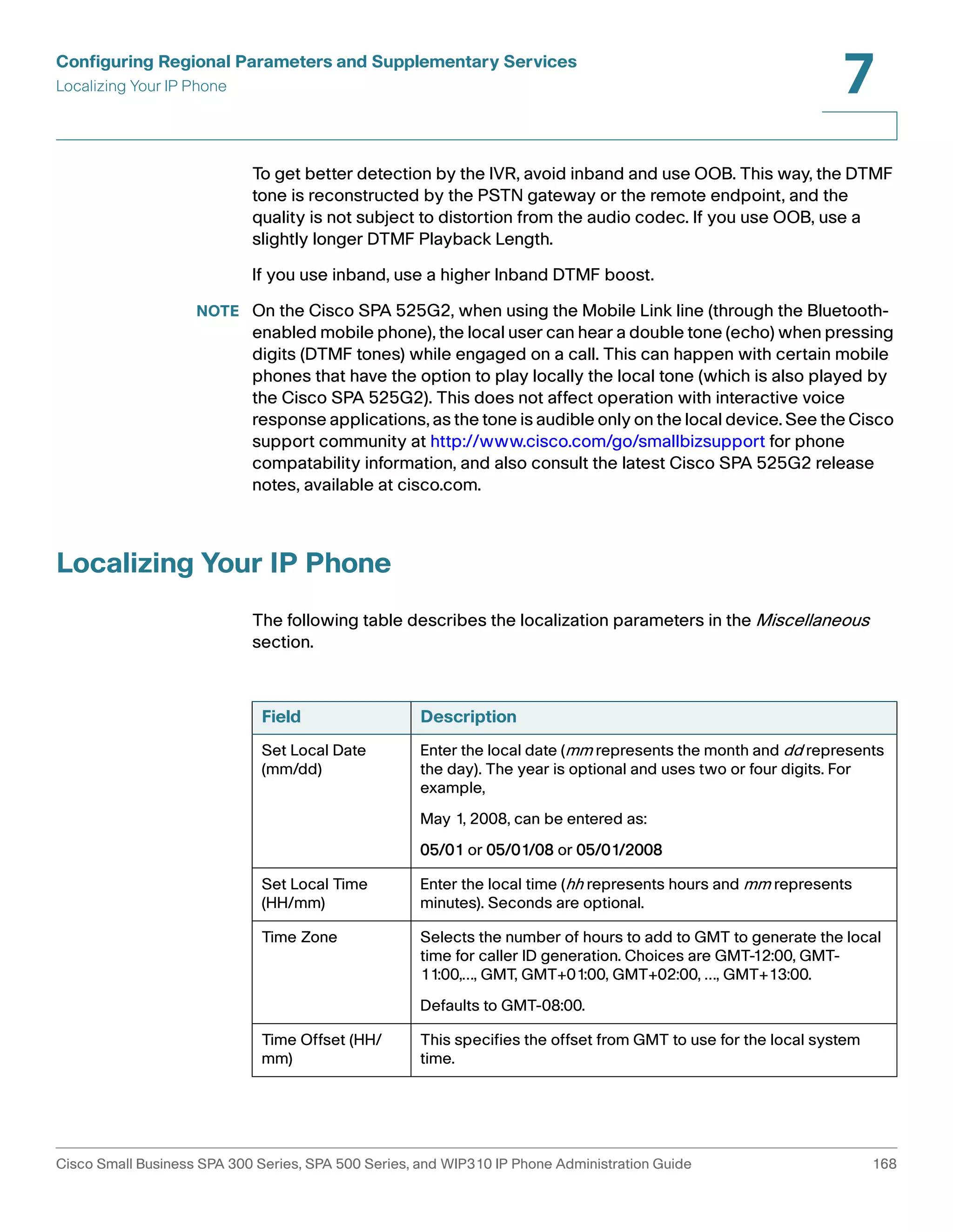
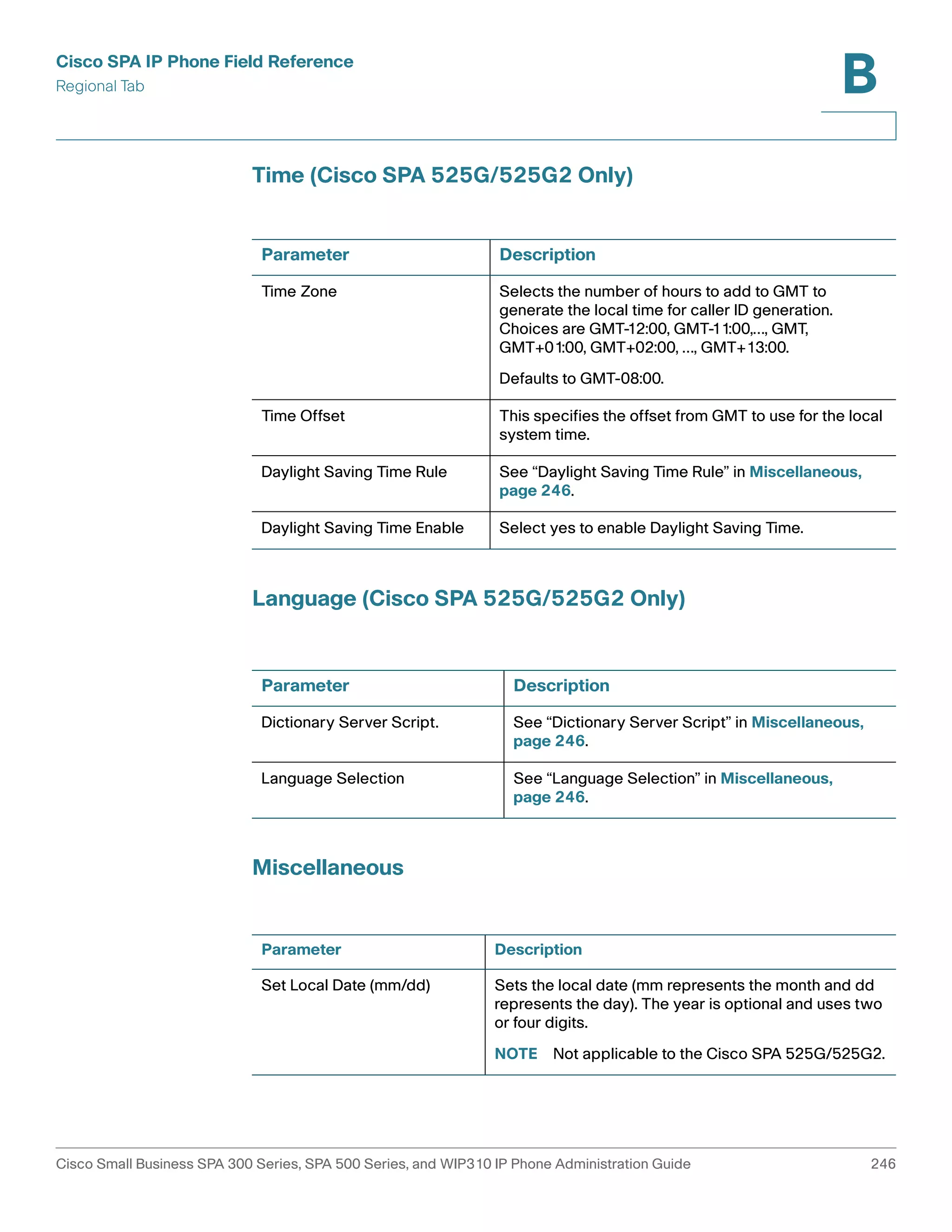
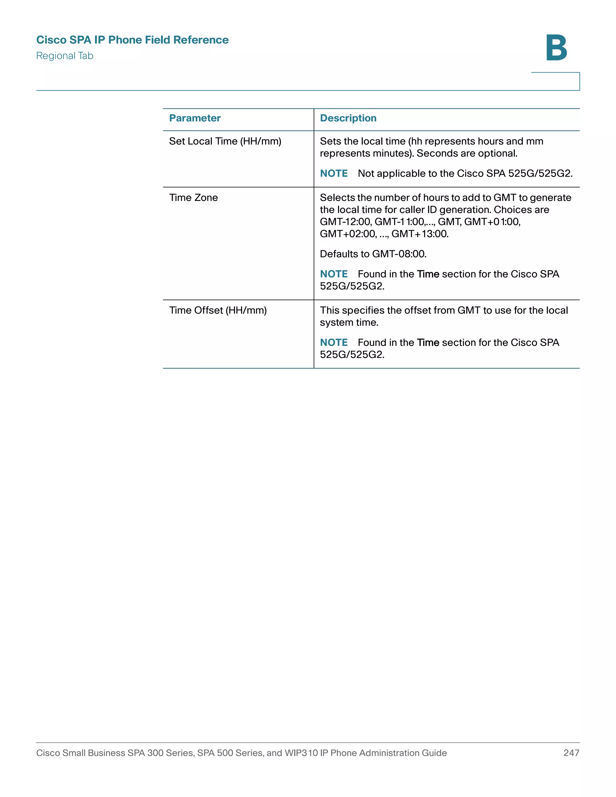
The time served by the NTP Server and the SIP Date Header are expressed in
GMT time. The local time is obtained by offsetting the GMT according to the time
zone of the region.
The Time Zone parameter can be configured from the web page or through
provisioning. This time can be further offset by the Time Offset (HH/mm)
parameter, which must be entered in 24-hour format. This parameter can also be
configured from the phone’s LCD display.
NOTE The Time Zone and Time Offset (HH/mm) offset values are not applied to manual
time and date setup.
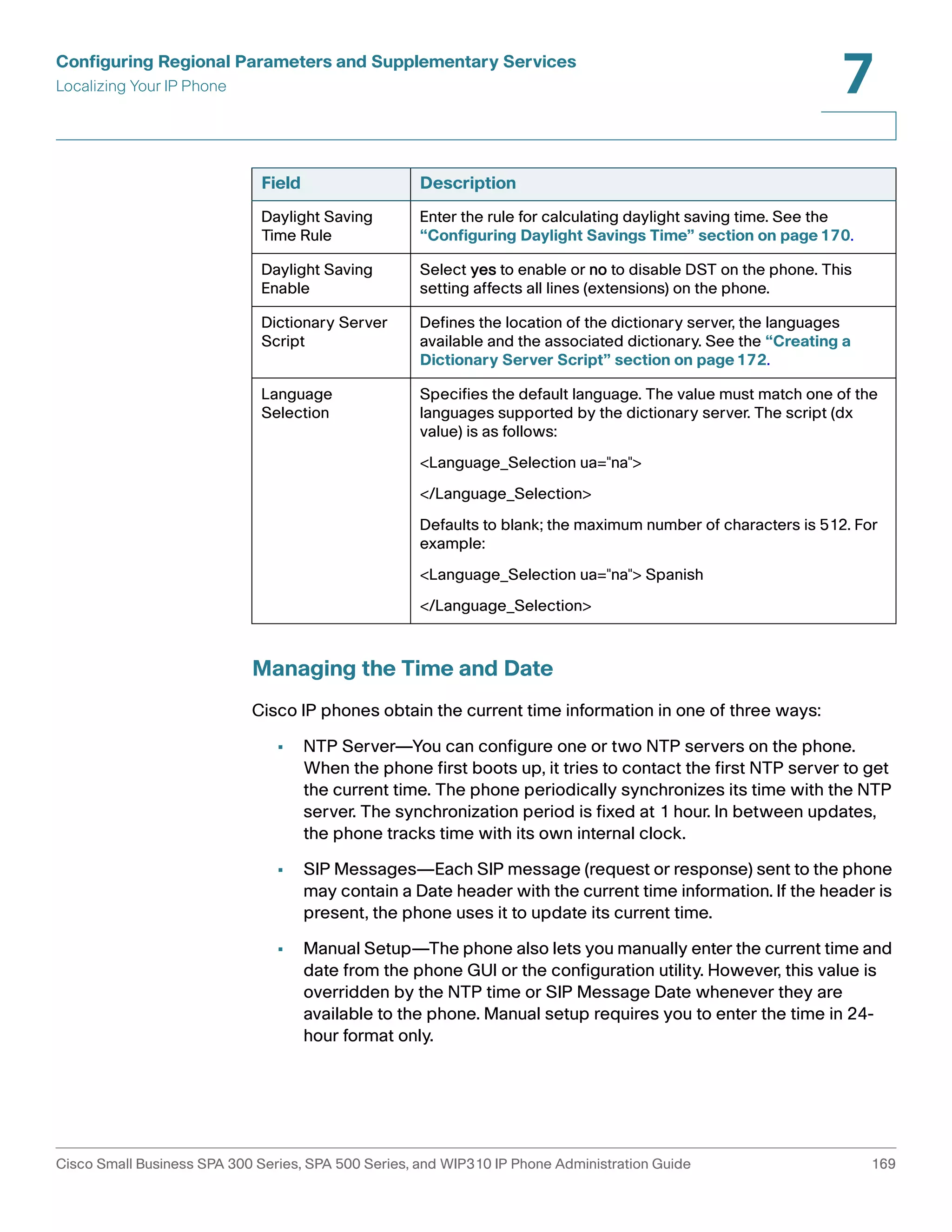
Configuring Daylight Savings Time
The phone supports auto adjustment for daylight saving time. You must set
Daylight Savings Time Enable to yes and enter the DST rule. This option affects the
time stamp on CallerID.
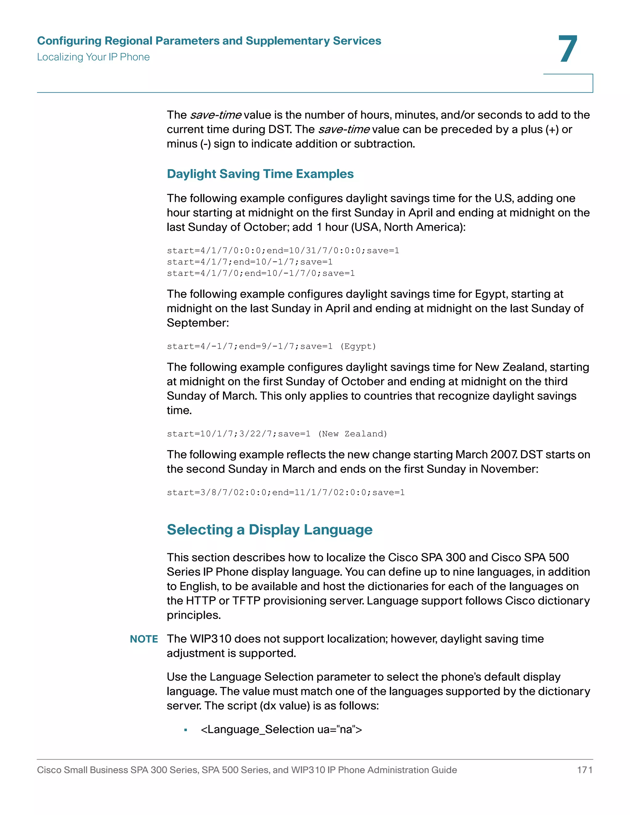
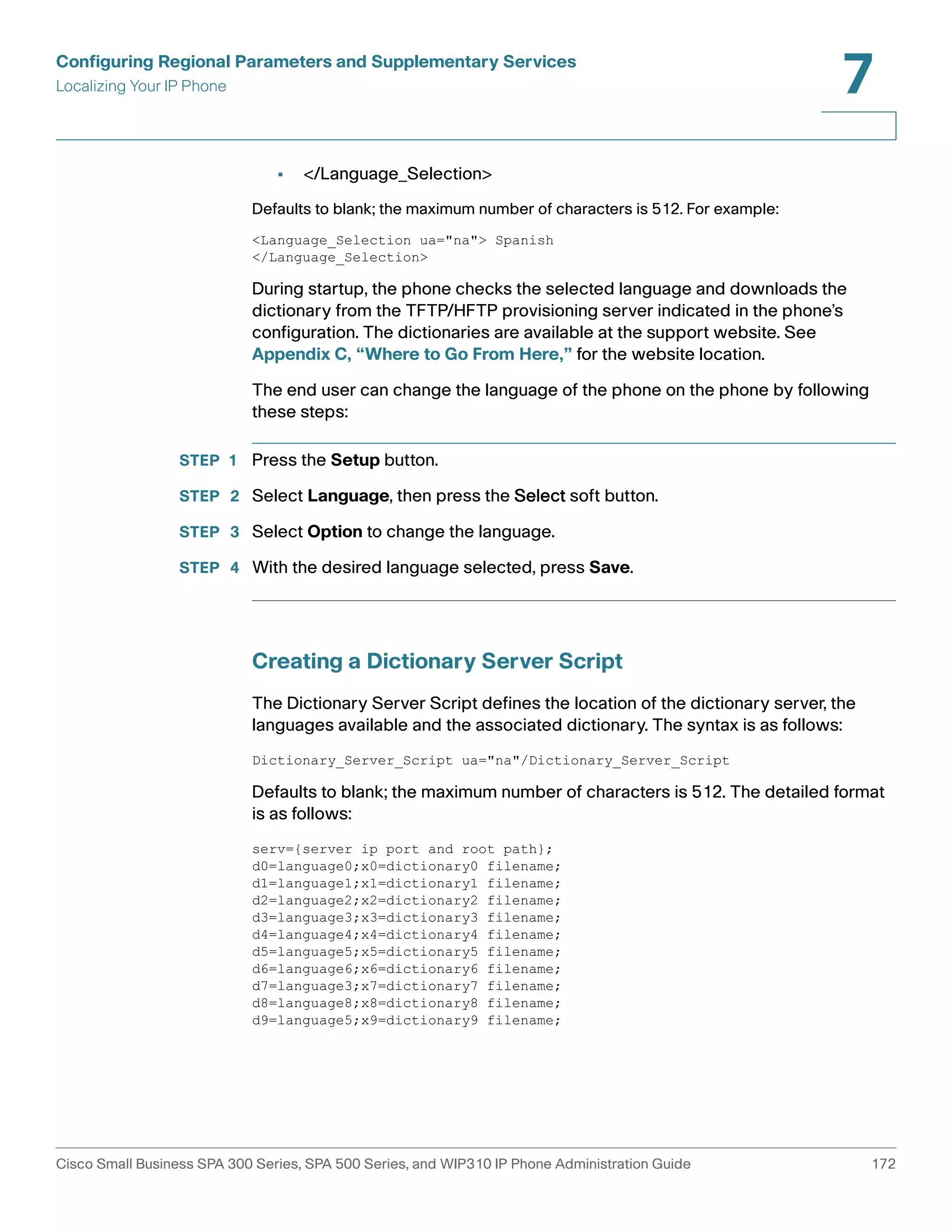
To enter the rule for calculating DST, include the start, end, and save values
separated by semi-colons (;) as follows:
Start = start-time; end=end-time; save = save-time
For example, the default DST rule is
start=4/1/7;end=10/-1/7;save=1.
The start-time and end-time values specify the start and end dates and times of
daylight saving time. Each value is in this format: month/day/ weekday[/HH:mm:ss]
The month value equals any value in the range 1-12 (January-December).
The day value equals any + or - value in the range 1-31. If day is 1, it means the
weekday on or before the end of the month (in other words the last occurrence of
weekday in that month).
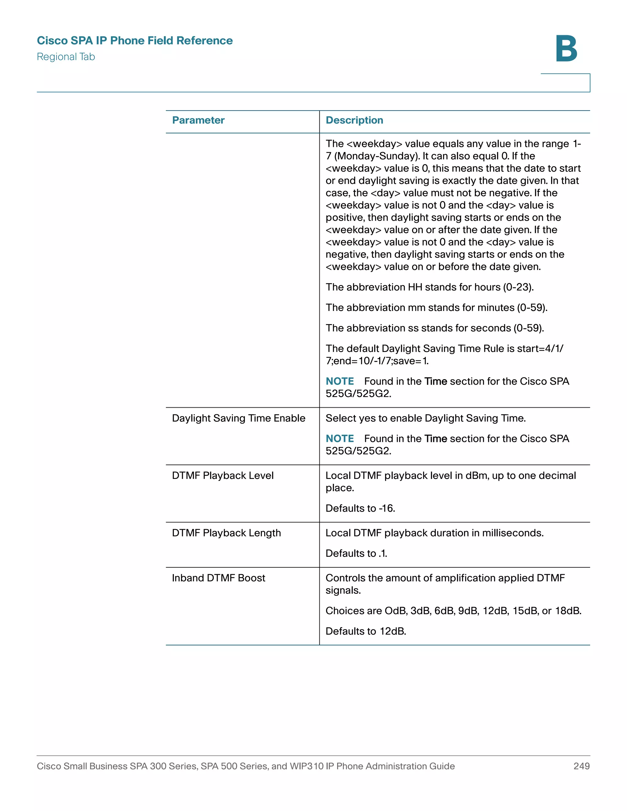
The weekday value equals any value in the range 1-7 (Monday-Sunday). It can also
equal 0. If the weekday value is 0, this means that the date to start or end daylight
saving is exactly the date given. In that case, the day value must not be negative. If
the weekday value is not 0 and the day value is positive, then daylight saving starts
or ends on the weekday value on or after the date given. If the weekday value is
not 0 and the day value is negative, then daylight saving starts or ends on the
weekday value on or before the date given.
Optional time values: HH represents hours (0-23), mm represents minutes (0-59).
and ss represents seconds (0-59). Optional values inside brackets [ ] are assumed
to be 0 if not specified. Midnight is represented by 0:0:0 of the given date.
Cisco Small Business SPA 300 Series, SPA 500 Series, and WIP310 IP Phone Administration Guide 170](https://image.slidesharecdn.com/ciscospa303-administrationguide-141015151631-conversion-gate02/75/Cisco-spa303-administration-guide-182-2048.jpg)
![Configuring Dial Plans
About Dial Plans
8
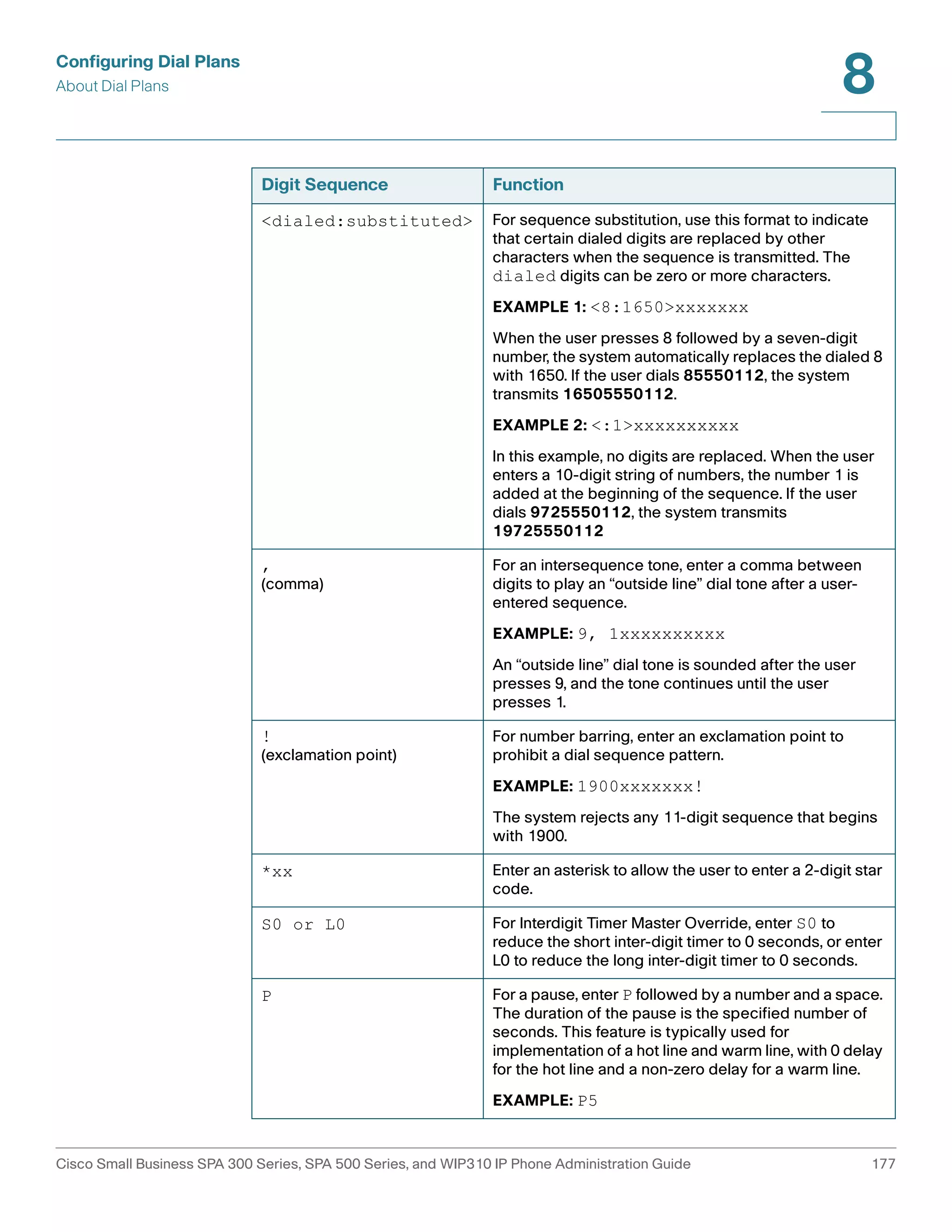
Digit Sequences
A dial plan contains a series of digit sequences, separated by the | character. The
entire collection of sequences is enclosed within parentheses. Each digit
sequence within the dial plan consists of a series of elements, which are
individually matched to the keys that the user presses.
NOTE White space is ignored, but may be used for readability.
Digit Sequence Function
0 1 2 3 4 5 6 7 8 9 0
* #
Enter any of these characters to represent a key that
the user must press on the phone keypad.
x Enter x to represent any character on the phone
keypad.
[sequence] Enter characters within square brackets to create a list
of accepted key presses. The user can press any one
of the keys in the list.
• Numeric range
For example, you would enter [2-9] to allow the
user to press any one digit from 2 through 9.
• Numeric range with other characters
For example, you would enter [35-8*] to allow
the user to press 3, 5, 6, 7, 8, or *.
.
(period)
Enter a period for element repetition. The dial plan
accepts 0 or more entries of the digit. For example,
01. allows users to enter 0, 01, 011, 0111, and so on.
Cisco Small Business SPA 300 Series, SPA 500 Series, and WIP310 IP Phone Administration Guide 176](https://image.slidesharecdn.com/ciscospa303-administrationguide-141015151631-conversion-gate02/75/Cisco-spa303-administration-guide-188-2048.jpg)
![Configuring Dial Plans
About Dial Plans
8
NOTE The Cisco SPA 9000 and the Cisco IP phones implicitly append the vertical code
sequences entered in the regional parameter settings to the end of the dial plan.
Likewise, if Enable_IP_Dialing is enabled, then IP dialing is also accepted on the
associated line.
Digit Sequence Examples
The following examples show digit sequences that you can enter in a dial plan.
In a complete dial plan entry, sequences are separated by a pipe character (|), and
the entire set of sequences is enclosed within parentheses.
EXAMPLE: ( [1-8]xx | 9, xxxxxxx | 9, <:1>[2-9]xxxxxxxxx | 8,
<:1212>xxxxxxx | 9, 1 [2-9] xxxxxxxxx | 9, 1 900 xxxxxxx ! |
9, 011xxxxxx. | 0 | [49]11 )
• Extensions on your system
EXAMPLE: ( [1-8]xx | 9, xxxxxxx | 9, <:1>[2-9]xxxxxxxxx |
8, <:1212>xxxxxxx | 9, 1 [2-9] xxxxxxxxx | 9, 1 900
xxxxxxx ! | 9, 011xxxxxx. | 0 | [49]11 )
[1-8]xx Allows a user dial any three-digit number that starts with the digits 1
through 8. If your system uses four-digit extensions, you would instead enter
the following string: [1-8]xxx
• Local dialing with seven-digit number
EXAMPLE: ( [1-8]xx | 9, xxxxxxx | 9, <:1>[2-9]xxxxxxxxx | 8,
<:1212>xxxxxxx | 9, 1 [2-9] xxxxxxxxx | 9, 1 900 xxxxxxx
! | 9, 011xxxxxx. | 0 | [49]111)
9, xxxxxxx After a user presses 9, an external dial tone sounds. The user can
enter any seven-digit number, as in a local call.
• Local dialing with 3-digit area code and a 7-digit local number
EXAMPLE: ( [1-8]xx | 9, xxxxxxx | 9, <:1>[2-9]xxxxxxxxx | 8,
<:1212>xxxxxxx | 9, 1 [2-9] xxxxxxxxx | 9, 1 900 xxxxxxx
! | 9, 011xxxxxx. | 0 | [49]11 )
9, <:1>[2-9]xxxxxxxxx This example is useful where a local area code is
required. After a user presses 9, an external dial tone sounds. The user must
enter a 10-digit number that begins with a digit 2 through 9. The system
automatically inserts the 1 prefix before transmitting the number to the
carrier.
Cisco Small Business SPA 300 Series, SPA 500 Series, and WIP310 IP Phone Administration Guide 178](https://image.slidesharecdn.com/ciscospa303-administrationguide-141015151631-conversion-gate02/75/Cisco-spa303-administration-guide-190-2048.jpg)
![Configuring Dial Plans
About Dial Plans
8
• Local dialing with an automatically inserted 3-digit area code
EXAMPLE: ( [1-8]xx | 9, xxxxxxx | 9, <:1>[2-9]xxxxxxxxx
| 8, <:1212>xxxxxxx | 9, 1 [2-9] xxxxxxxxx | 9, 1 900 xxxxxxx
! | 9, 011xxxxxx. | 0 | [49]11 )
8, <:1212>xxxxxxx This is example is useful where a local area code is
required by the carrier but the majority of calls go to one area code. After
the user presses 8, an external dial tone sounds. The user can enter any
seven-digit number. The system automatically inserts the 1 prefix and the
212 area code before transmitting the number to the carrier.
• U.S. long distance dialing
EXAMPLE: ( [1-8]xx | 9, xxxxxxx | 9, <:1>[2-9]xxxxxxxxx
| 8, <:1212>xxxxxxx | 9, 1 [2-9] xxxxxxxxx | 9, 1 900 xxxxxxx !
| 9, 011xxxxxx. | 0 | [49]11 )
9, 1 [2-9] xxxxxxxxx After the user presses 9, an external dial tone sounds. The
user can enter any 11-digit number that starts with 1 and is followed by a
digit 2 through 9.
• Blocked number
EXAMPLE: ( [1-8]xx | 9, xxxxxxx | 9, <:1>[2-9]xxxxxxxxx
| 8, <:1212>xxxxxxx | 9, 1 [2-9] xxxxxxxxx | 9, 1 900 xxxxxxx
! | 9, 011xxxxxx. | 0 | [49]11 )
9, 1 900 xxxxxxx ! This digit sequence is useful if you want to prevent users
from dialing numbers that are associated with high tolls or inappropriate
content, such as 1-900 numbers in the U.S.. After the user press 9, an
external dial tone sounds. If the user enters an 11-digit number that starts
with the digits 1900, the call is rejected.
• U.S. international dialing
EXAMPLE: ( [1-8]xx | 9, xxxxxxx | 9, <:1>[2-9]xxxxxxxxx
| 8, <:1212>xxxxxxx | 9, 1 [2-9] xxxxxxxxx | 9, 1 900
xxxxxxx ! | 9, 011xxxxxx. | 0 | [49]11 )
9, 011xxxxxx. After the user presses 9, an external dial tone sounds. The user
can enter any number that starts with 011, as in an international call from the
U.S.
• Informational numbers
Cisco Small Business SPA 300 Series, SPA 500 Series, and WIP310 IP Phone Administration Guide 179](https://image.slidesharecdn.com/ciscospa303-administrationguide-141015151631-conversion-gate02/75/Cisco-spa303-administration-guide-191-2048.jpg)
![Configuring Dial Plans
About Dial Plans
8
EXAMPLE: ( [1-8]xx | 9, xxxxxxx | 9, <:1>[2-9]xxxxxxxxx |
8, <:1212>xxxxxxx | 9, 1 [2-9] xxxxxxxxx | 9, 1 900
xxxxxxx ! | 9, 011xxxxxx. | 0 | [49]11 )
0 | [49]11 This example includes two digit sequences, separated by the pipe
character. The first sequence allows a user to dial 0 for an operator. The
second sequence allows the user to enter 411 for local information or 911
for emergency services.
Acceptance and Transmission of the Dialed Digits
When a user dials a series of digits, each sequence in the dial plan is tested as a
possible match. The matching sequences form a set of candidate digit sequences.
As more digits are entered by the user, the set of candidates diminishes until only
one or none are valid. When a terminating event occurs, the IP PBX either accepts
the user-dialed sequence and initiates a call, or else rejects the sequence as
invalid. The user hears the reorder (fast busy) tone if the dialed sequence is invalid.
The following table explains how terminating events are processed.
Terminating Event Processing
The dialed digits do not match any
sequence in the dial plan.
The number is rejected.
The dialed digits exactly match
one sequence in the dial plan.
• If the sequence is allowed by the dial plan, the
number is accepted and is transmitted
according to the dial plan.
• If the sequence is blocked by the dial plan, the
number is rejected.
A timeout occurs. The number is rejected if the dialed digits are not
matched to a digit sequence in the dial plan within
the time specified by the applicable interdigit
timer.
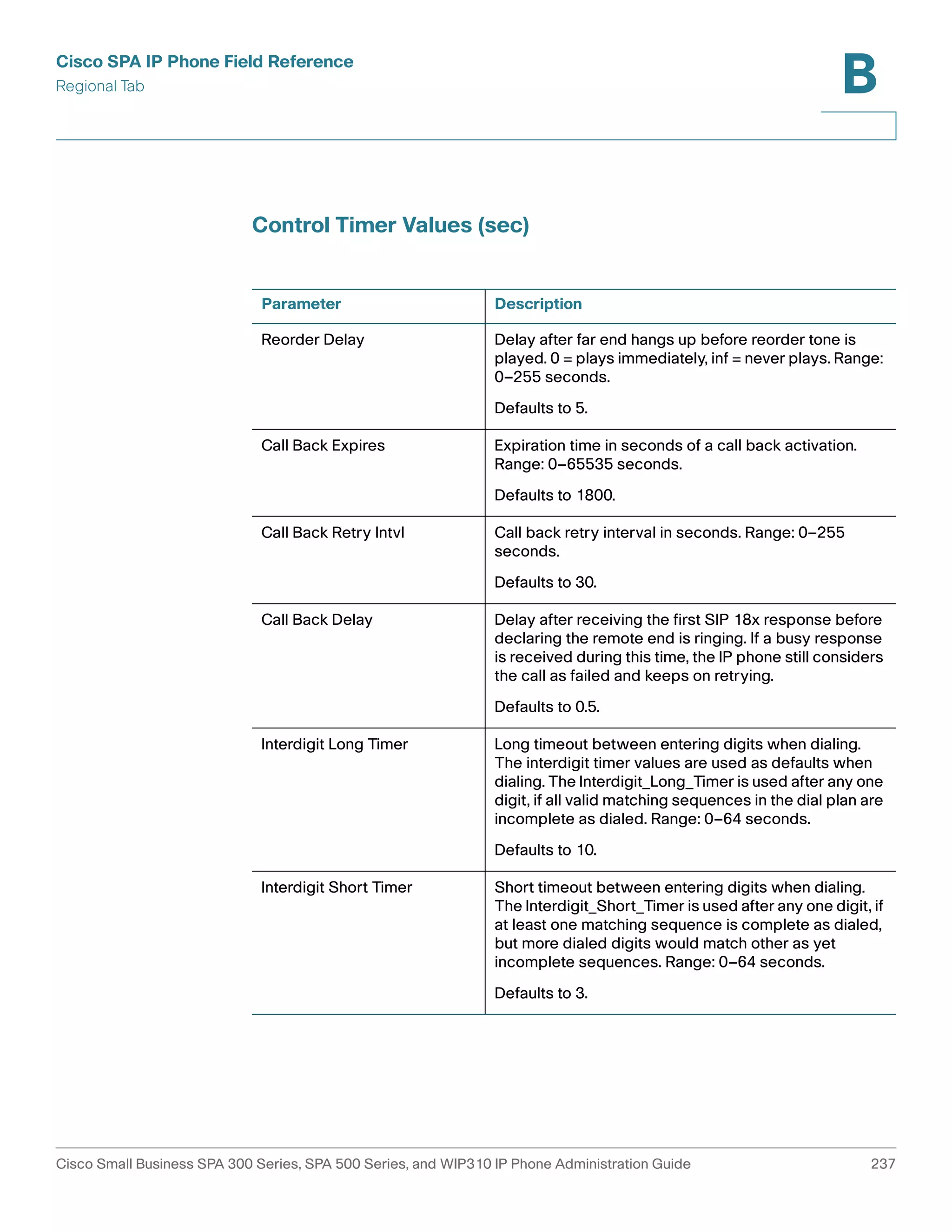
• The Interdigit Long Timer applies when the
dialed digits do not match any digit sequence
in the dial plan. The default value is 10
seconds.
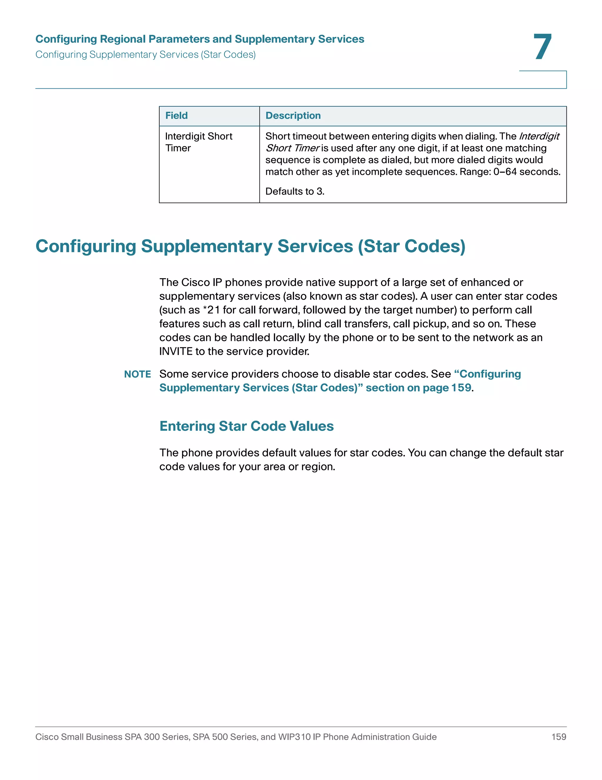
• The Interdigit Short Timer applies when the
dialed digits match one or more candidate
sequences in the dial plan. The default value is
3 seconds.
Cisco Small Business SPA 300 Series, SPA 500 Series, and WIP310 IP Phone Administration Guide 180](https://image.slidesharecdn.com/ciscospa303-administrationguide-141015151631-conversion-gate02/75/Cisco-spa303-administration-guide-192-2048.jpg)
![Configuring Dial Plans
About Dial Plans
8
Terminating Event Processing
The user presses the # key or the
dial softkey on the phone display.
• If the sequence is complete and is allowed by
the dial plan, the number is accepted and is
transmitted according to the dial plan.
• If the sequence is incomplete or is blocked by
the dial plan, the number is rejected.
Dial Plan Timer (Off-Hook Timer)
You can think of the Dial Plan Timer as “the off-hook timer.” This timer starts
counting when the phone goes off hook. If no digits are dialed within the specified
number of seconds, the timer expires and the null entry is evaluated. Unless you
have a special dial plan string to allow a null entry, the call is rejected. The default
value is 5.
Syntax for the Dial Plan Timer
SYNTAX: (Ps<:n> | dial plan )
• s: The number of seconds; if no number is entered after P, the default timer of 5
seconds applies.
• n: (optional): The number to transmit automatically when the timer expires; you
can enter an extension number or a DID number. No wildcard characters are
allowed because the number will be transmitted as shown. If you omit the
number substitution, <:n>, then the user hears a reorder (fast busy) tone after
the specified number of seconds.
Examples for the Dial Plan Timer
• Allow more time for users to start dialing after taking a phone off hook.
EXAMPLE: (P9 | (9,8<:1408>[2-9]xxxxxx | 9,8,1[2-
9]xxxxxxxxx | 9,8,011xx. | 9,8,xx.|[1-8]xx)
P9 After taking a phone off hook, a user has 9 seconds to begin dialing. If no
digits are pressed within 9 seconds, the user hears a reorder (fast busy)
tone. By setting a longer timer, you allow more time for users to enter the
digits.
• Create a hotline for all sequences on the System Dial Plan
EXAMPLE: (P9<:23> | (9,8<:1408>[2-9]xxxxxx | 9,8,1[2-
9]xxxxxxxxx | 9,8,011xx. | 9,8,xx.|[1-8]xx)
Cisco Small Business SPA 300 Series, SPA 500 Series, and WIP310 IP Phone Administration Guide 181](https://image.slidesharecdn.com/ciscospa303-administrationguide-141015151631-conversion-gate02/75/Cisco-spa303-administration-guide-193-2048.jpg)
![Configuring Dial Plans
About Dial Plans
8
P9<:23> After taking the phone off hook, a user has 9 seconds to begin
dialing. If no digits are pressed within 9 seconds, the call is transmitted
automatically to extension 23.
• Create a hotline on a line button for an extension
EXAMPLE: ( P0 <:1000>)
With the timer set to 0 seconds, the call is transmitted automatically to the
specified extension when the phone goes off hook. Enter this sequence in
the Phone Dial Plan for Ext 2 or higher on a client station.
Interdigit Long Timer (Incomplete Entry Timer)
You can think of this timer as the “incomplete entry” timer. This timer measures the
interval between dialed digits. It applies as long as the dialed digits do not match
any digit sequences in the dial plan. Unless the user enters another digit within the
specified number of seconds, the entry is evaluated as incomplete, and the call is
rejected. The default value is 10 seconds.
NOTE This section explains how to edit a timer as part of a dial plan. Alternatively, you can
modify the Control Timer that controls the default interdigit timers for all calls. See
“Resetting the Control Timers,” on page185.
Syntax for the Interdigit Long Timer
SYNTAX: L:s, ( dial plan )
• s: The number of seconds; if no number is entered after L:, the default timer of
5 seconds applies.
• Note that the timer sequence appears to the left of the initial parenthesis for the
dial plan.
Example for the Interdigit Long Timer
EXAMPLE: L:15, (9,8<:1408>[2-9]xxxxxx | 9,8,1[2-9]xxxxxxxxx |
9,8,011xx. | 9,8,xx.|[1-8]xx)
L:15, This dial plan allows the user to pause for up to 15 seconds between digits
before the Interdigit Long Timer expires. This setting is especially helpful to users
such as sales people, who are reading the numbers from business cards and other
printed materials while dialing.
Cisco Small Business SPA 300 Series, SPA 500 Series, and WIP310 IP Phone Administration Guide 182](https://image.slidesharecdn.com/ciscospa303-administrationguide-141015151631-conversion-gate02/75/Cisco-spa303-administration-guide-194-2048.jpg)
![Configuring Dial Plans
About Dial Plans
8
Interdigit Short Timer (Complete Entry Timer)
You can think of this timer as the “complete entry” timer. This timer measures the
interval between dialed digits. It applies when the dialed digits match at least one
digit sequence in the dial plan. Unless the user enters another digit within the
specified number of seconds, the entry is evaluated. If it is valid, the call proceeds.
If it is invalid, the call is rejected. The default value is 3 seconds.
Syntax for the Interdigit Short Timer
• SYNTAX 1: S:s, ( dial plan )
Use this syntax to apply the new setting to the entire dial plan within the
parentheses.
• SYNTAX 2: sequence Ss
Use this syntax to apply the new setting to a particular dialing sequence.
s: The number of seconds; if no number is entered after S, the default timer
of 5 seconds applies.
Examples for the Interdigit Short Timer
• Set the timer for the entire dial plan.
EXAMPLE: S:6, (9,8<:1408>[2-9]xxxxxx | 9,8,1[2-
9]xxxxxxxxx | 9,8,011xx. | 9,8,xx.|[1-8]xx)
S:6, While entering a number with the phone off hook, a user can pause for
up to 15 seconds between digits before the Interdigit Short Timer expires.
This setting is especially helpful to users such as sales people, who are
reading the numbers from business cards and other printed materials while
dialing.
• Set an instant timer for a particular sequence within the dial plan.
EXAMPLE: (9,8<:1408>[2-9]xxxxxx | 9,8,1[2-9]xxxxxxxxxS0 |
9,8,011xx. | 9,8,xx.|[1-8]xx)
9,8,1[2-9]xxxxxxxxxS0 With the timer set to 0, the call is transmitted
automatically when the user dials the final digit in the sequence.
Cisco Small Business SPA 300 Series, SPA 500 Series, and WIP310 IP Phone Administration Guide 183](https://image.slidesharecdn.com/ciscospa303-administrationguide-141015151631-conversion-gate02/75/Cisco-spa303-administration-guide-195-2048.jpg)
![Configuring Dial Plans
Editing Dial Plans on the IP Phone
8
Editing Dial Plans on the IP Phone
You can edit dial plans and can modify the control timers. To edit the dial plans on
the IP phone:
STEP 1 Log in to the configuration utility.
STEP 2 Click Admin Login and advanced.
STEP 3 Click the Ext N tab, where N is the extension being configured.
STEP 4 In the Dial Plan section, enter the digit sequences in the Dial Plan field. For more
information and examples, see “Digit Sequences,” on page176.
The default (US-based) system-wide dial plan appears automatically in the
field. You can delete digit sequences, add digit sequences, or replace the
entire dial plan with a new dial plan. For more information and examples,
see “Digit Sequences,” on page176.
Separate each digit sequence with a pipe character, and enclose the entire
set of digit sequences within parentheses. Refer to the following example:
(9,8<:1408>[2-9]xxxxxx | 9,8,1[2-9]xxxxxxxxx |
9,8,011xx. | 9,8,xx.|[1-8]xx)
STEP 5 (Optional) Enter the Caller ID Map—Inbound caller ID numbers can be mapped to a
different string. For example, a number that begins with +44xxxxxx can be
mapped to 0xxxxxx. This feature has the same syntax as the Dial Plan parameter.
With this parameter, you can specify how to map a caller ID number for display on
screen and recorded into call logs. (Not applicable to WIP310.)
STEP 6 (Optional) Enable IP dialing—Enable or disable IP dialing. Defaults to no.
STEP 7 (Optional) Emergency Number—Enter a comma-separated list of emergency
numbers. When one of these numbers is dialed, the unit disables processing of
CONF, HOLD, and other similar softkeys or buttons to avoid accidentally putting the
current call on hold. The phone also disables hook flash event handling. Only the
far end can terminate an emergency call. The phone is restored to normal after the
call is terminated and the phone is back on-hook.
Maximum number length is 63 characters. Defaults to blank (no emergency
number). (Not applicable to WIP310.)
STEP 8 Click Submit All Changes. The phone reboots.
Cisco Small Business SPA 300 Series, SPA 500 Series, and WIP310 IP Phone Administration Guide 184](https://image.slidesharecdn.com/ciscospa303-administrationguide-141015151631-conversion-gate02/75/Cisco-spa303-administration-guide-196-2048.jpg)
![Configuring the Cisco SPA 500S Attendant Console
Setting Up the Cisco SPA 500S Attendant Console
9
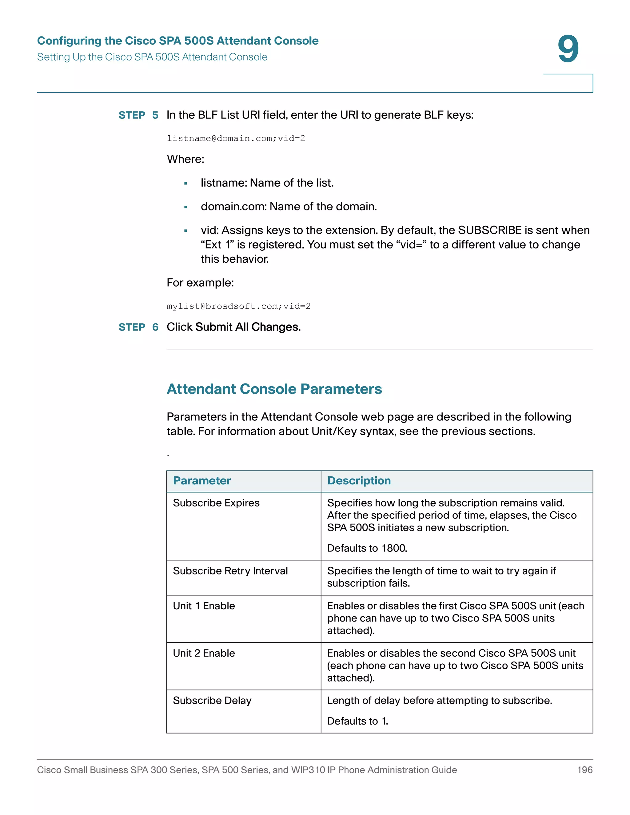
STEP 4 On the Busy Lamp Field page, move users that need to be monitored from the
Available Users column to the Monitored Users column.
STEP 5 Click the Add (or Add All) button to move each user to the Monitored Users
column. The Directory Number (DN) associated with each user account when it is
created on the BroadSoft Server is shown in parenthesis in the Monitored Users
list. You use this DN to identify the specific phone assigned to each key on the
Cisco SPA 500S.
STEP 6 Save and enable your configuration changes on the BroadSoft server.
See also the “Configuring BroadSoft Busy Lamp Field Auto-Configuration”
section on page195.
Configuring the Asterisk Server for the Cisco SPA 500S
To configure the Asterisk server to allow the Cisco SPA 500S to register for BLF
monitoring:
STEP 1 Add a context in the extensions.conf file.
STEP 2 Add a Subscribecontext command to point to the context in the sip.conf file.
STEP 3 Configure the Cisco SPA 500S to register with the Asterisk server (see
“Configuring the Cisco SPA 500S” section on page191.
The following example context uses “home” for extension 3500. This is entered in
the file extensions.conf:
[home]
exten => 3500,1,Dial(SIP/3500)
exten => 3500,hint,SIP/3500
exten => 3500,2,Voicemail,u3500
exten =>3500,1,3,hangup
...
In the following example, extension 3500 is used to add Subscribecontext to
point to the context.
Cisco Small Business SPA 300 Series, SPA 500 Series, and WIP310 IP Phone Administration Guide 190](https://image.slidesharecdn.com/ciscospa303-administrationguide-141015151631-conversion-gate02/75/Cisco-spa303-administration-guide-202-2048.jpg)
![Configuring the Cisco SPA 500S Attendant Console
Setting Up the Cisco SPA 500S Attendant Console
9
This is entered in the file sip.conf:
[3500]
type=friend
secret=3500
callerid="spa3500"<3500>
nat=no
context=home
mailbox=3500
Subscribecontext=home
...
...
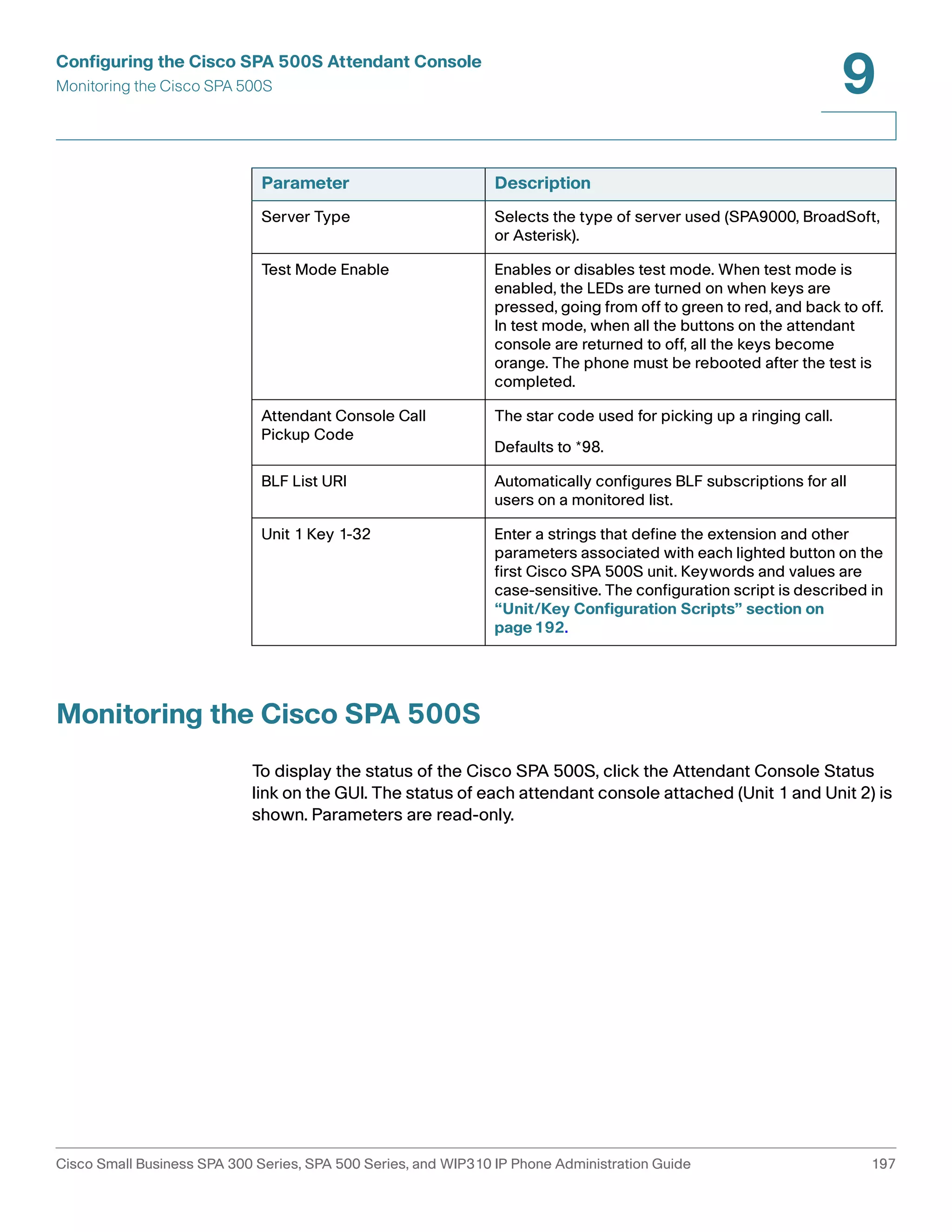
Configuring the Cisco SPA 500S
Complete the configuration required for the extensions on your IP PBX and obtain
the following information:
• IP PBX IP address or other hostname
• Phone extension numbers
To configure the Cisco SPA 500S:
NOTE Steps 1 through 4 are only required when the Server Type field is set to SPA9000.
These steps are not required for other server types such as BroadSoft and
Asterisk.
STEP 1 Connect to the configuration utility for the phone to which the Cisco SPA 500S is
connected.
STEP 2 Click Admin/Advanced on the configuration utility page.
STEP 3 Click the SIP tab.
STEP 4 Select yes from the CTI Enable drop-down list.
STEP 5 Click the Attendant Console tab.
STEP 6 Select yes from the Unit 1 Enable drop-down list. If you have installed two Cisco
SPA 500S units, also select yes from the Unit 2 Enable drop-down list.
Cisco Small Business SPA 300 Series, SPA 500 Series, and WIP310 IP Phone Administration Guide 191](https://image.slidesharecdn.com/ciscospa303-administrationguide-141015151631-conversion-gate02/75/Cisco-spa303-administration-guide-203-2048.jpg)
![Configuring the Cisco SPA 500S Attendant Console
Setting Up the Cisco SPA 500S Attendant Console
9
STEP 7 Select your Server Type from the drop-down list:
• SPA9000
• BroadSoft
• Asterisk
STEP 8 Make sure that no is selected for Test Mode Enable. This option is disabled by
default. You cannot complete the software configuration for the Cisco SPA 500S if
this option is enabled. (You can use Test Mode Enable later to test the Cisco SPA
500S.)
STEP 9 Create a configuration script for each target extension or user you want to monitor
using the Cisco SPA 500S. Enter this script in the appropriate field for each unit/
key. See “Unit/Key Configuration Scripts” section on page192.
STEP 10 Click Submit All Changes.
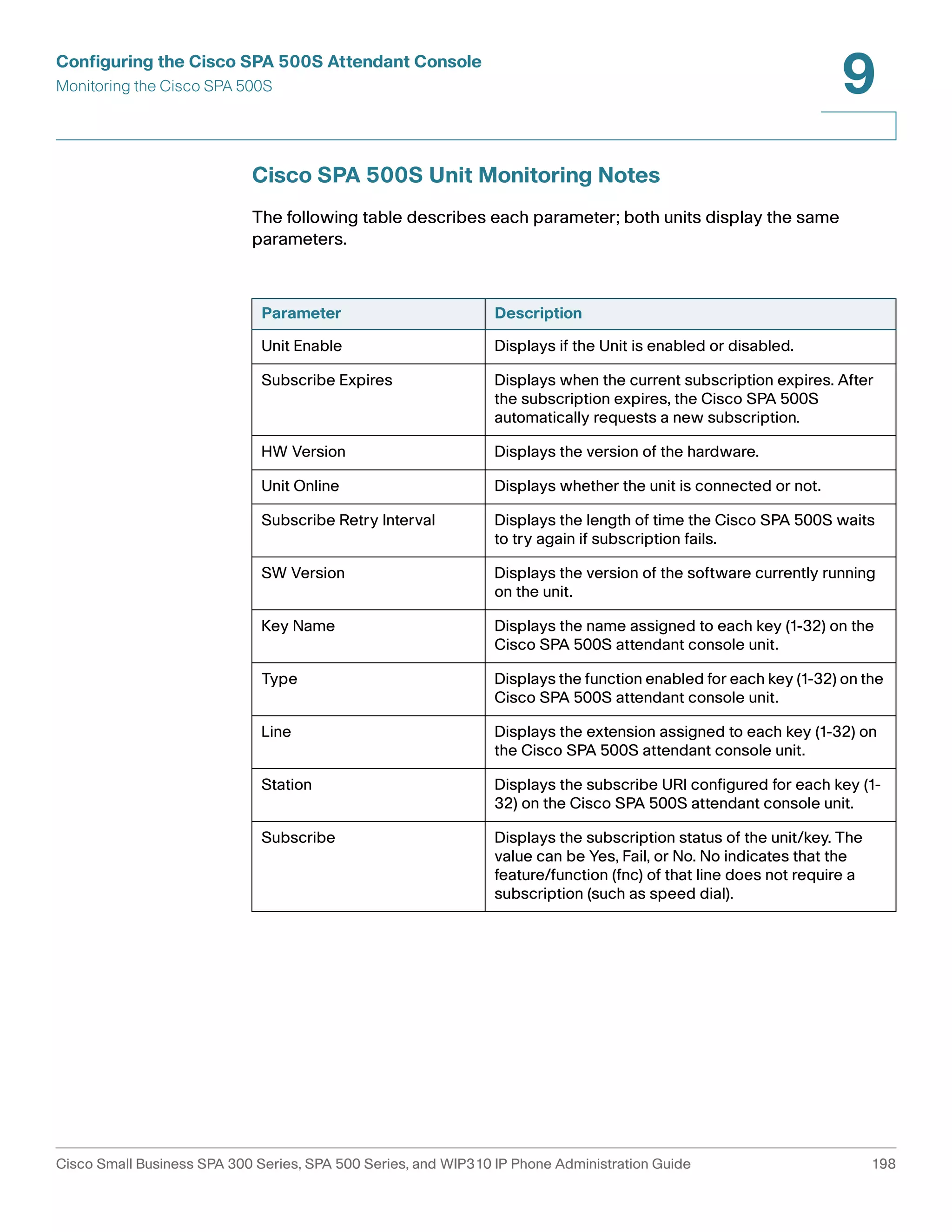
Unit/Key Configuration Scripts
By default, all LEDs on the Cisco SPA 500S are assigned to the first configured
extension on the phone to which it is connected. Assign the LEDs to any of the
other five extensions on the phone that you want to monitor using the Cisco SPA
500S.
The configuration script is composed of the following keywords, followed by an
equal sign (=) and separated by semicolons (;):
• fnc—defines which of the following functions are enabled for the specified key
[separate more than one function with a plus sign (+)]:
• blf—busy lamp field function used for monitoring line activity
• sd—speed dial function
• cp—call pickup (if supported by the SIP proxy server). Call pickup (cp) must
be supported by the SIP proxy server and be used with blf in the
configuration. The syntax is fnc=blf+cp.
Cisco Small Business SPA 300 Series, SPA 500 Series, and WIP310 IP Phone Administration Guide 192](https://image.slidesharecdn.com/ciscospa303-administrationguide-141015151631-conversion-gate02/75/Cisco-spa303-administration-guide-204-2048.jpg)
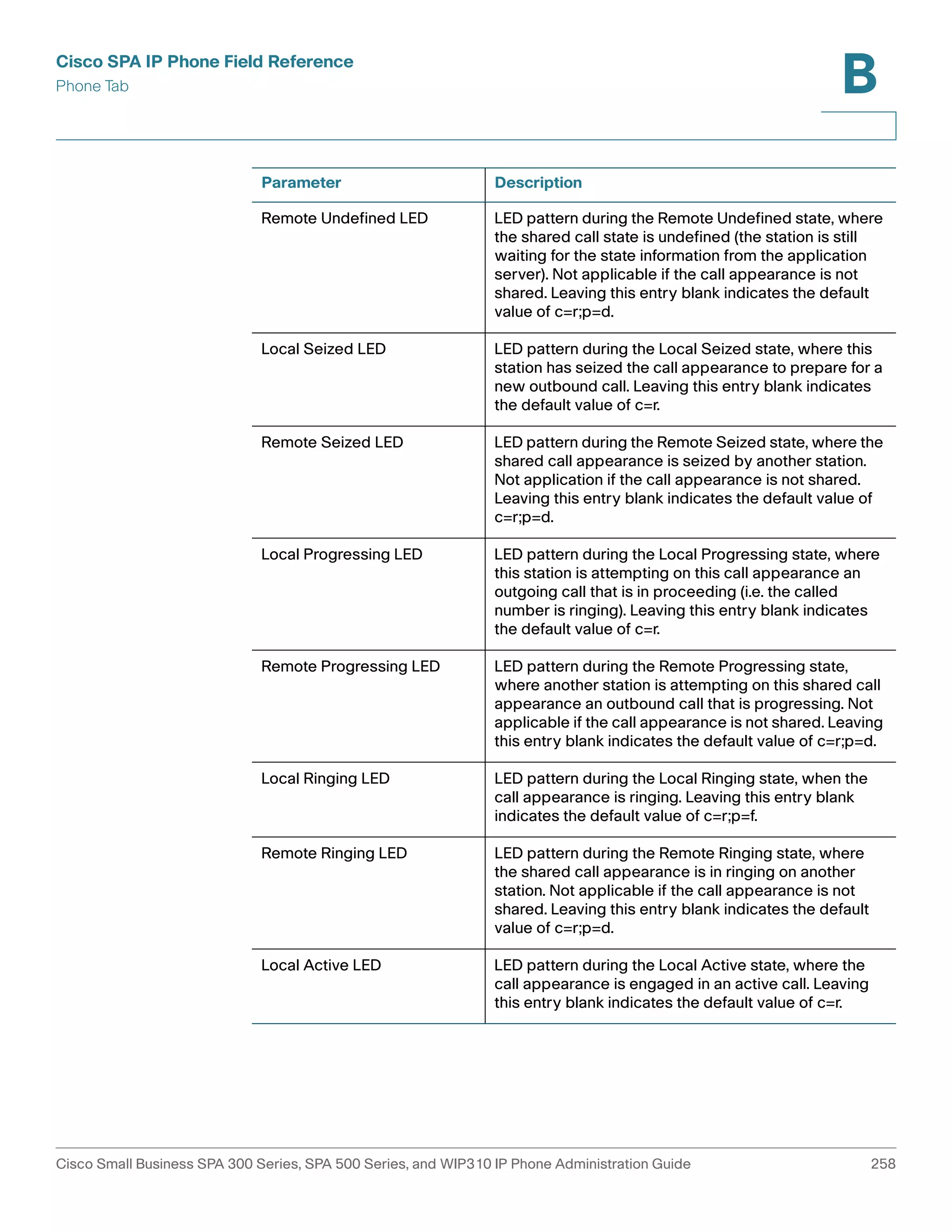
![A
Creating an LED Script
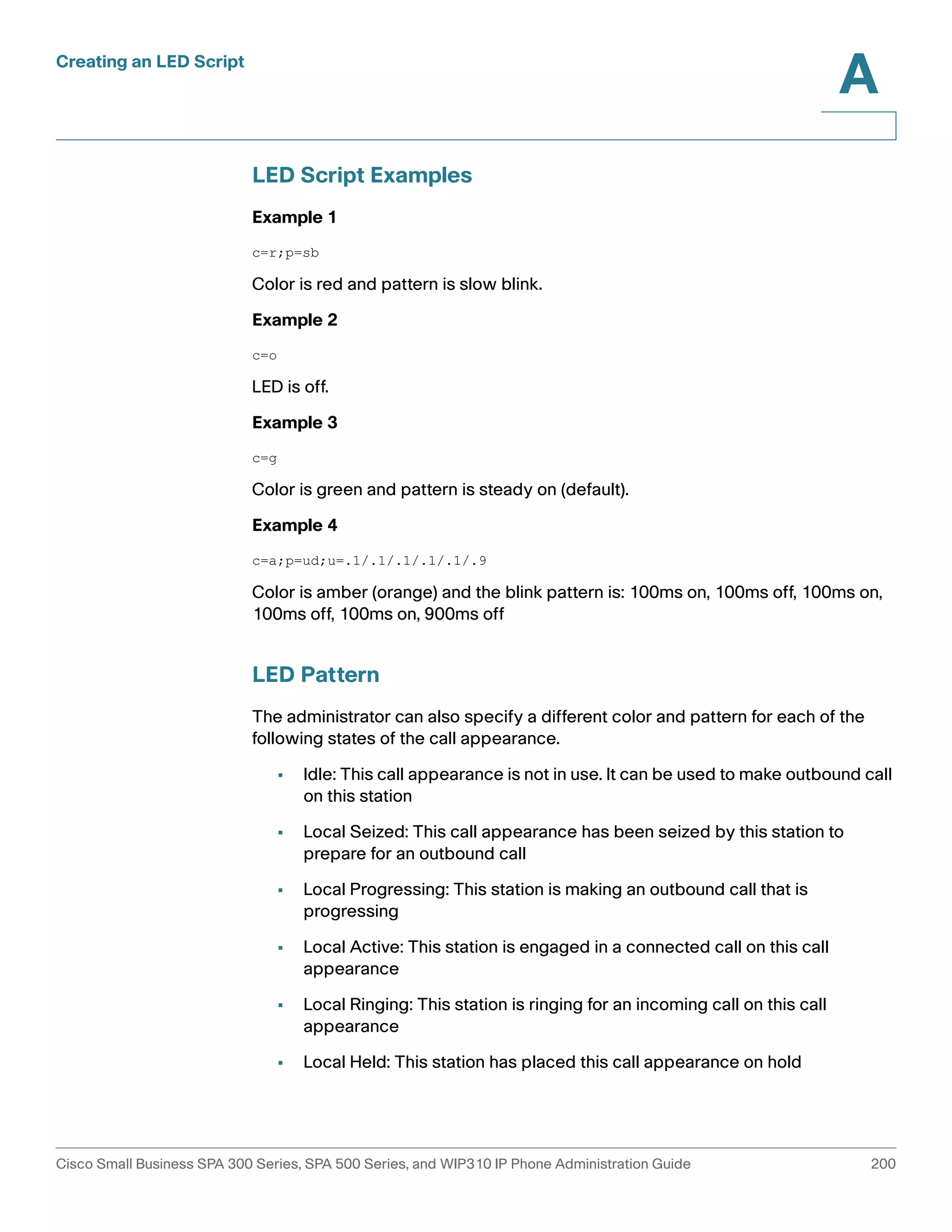
LED Script
The LED script describes the color and blinking pattern of a Line Key LED. Each
script contains a number of fields separated by a semicolon(;). White spaces are
ignored. Each field has the syntax <field-name> = <field-value>. The allowed
field-name and corresponding field-values are listed below:
c=o|r|g|a
This field sets the color of the LED. The 4 choices are:
• o = off
• r = red
• g = green
• a = amber (orange)
p=n[b]|s[b]|f[b]|d[b]|u[d]
This field sets the blinking pattern of the LED. The 4 choices are:
• nb = no blink (steady on or off)
• sb = slow blink (1s on and 1s off)
• fb = fast blink (100ms on and 100ms off)
• ud = user-defined (according to the contents of the u field)
u=on/off/on/off/etc.
This is a user-defined blinking pattern used only when p = ud. It consists of up to 4
pairs of on/off duration in seconds with up to 2 decimal places; each value is
separated by a forward slash (/).
Cisco Small Business SPA 300 Series, SPA 500 Series, and WIP310 IP Phone Administration Guide 199](https://image.slidesharecdn.com/ciscospa303-administrationguide-141015151631-conversion-gate02/75/Cisco-spa303-administration-guide-211-2048.jpg)
![Cisco SPA IP Phone Field Reference
Regional Tab
B
Parameter Description
Daylight Saving Time Rule Enter the rule for calculating daylight saving time; it
should include the start, end, and save values. This rule
is comprised of three fields. Each field is separated by ;
(a semicolon) as shown below. Optional values inside [ ]
(the brackets) are assumed to be 0 if they are not
specified. Midnight is represented by 0:0:0 of the given
date.
This is the format of the rule: Start = <start-time>;
end=<end-time>; save = <save-time>.
The <start-time> and <end-time> values specify the
start and end dates and times of daylight saving time.
Each value is in this format: <month> /<day> /
<weekday>[/HH:[mm[:ss]]]
The <save-time> value is the number of hours, minutes,
and/or seconds to add to the current time during
daylight saving time. The <save-time> value can be
preceded by a negative (-) sign if subtraction is desired
instead of addition. The <save-time> value is in this
format: [/[+|-]HH:[mm[:ss]]]
The <month> value equals any value in the range 1-12
(January-December).
The <day> value equals [+|-] any value in the range 1-
31.
If <day> is 1, it means the <weekday> on or before the
end of the month (in other words the last occurrence of
< weekday> in that month).
Cisco Small Business SPA 300 Series, SPA 500 Series, and WIP310 IP Phone Administration Guide 248](https://image.slidesharecdn.com/ciscospa303-administrationguide-141015151631-conversion-gate02/75/Cisco-spa303-administration-guide-260-2048.jpg)
![Cisco SPA IP Phone Field Reference
Phone Tab
B
Multiple Paging Group Parameters
Parameter Description
Group Paging Script You can configure a phone as part of a paging group.
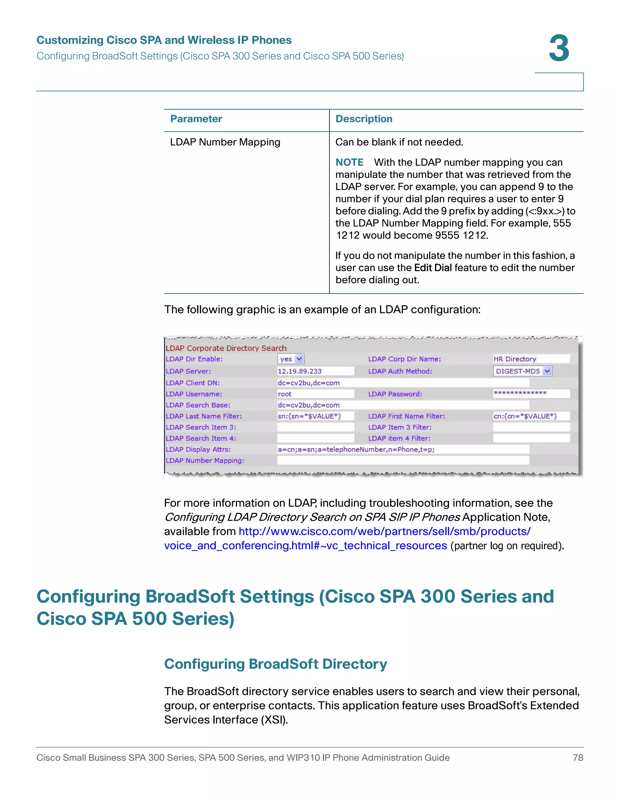
BroadSoft Settings
Users can then direct pages to specific groups of
phones. A phone can be part of no more than two
paging groups, and user can page a maximum of five
paging groups.
The syntax is as follows:
pggrp=ip-address:port;[name=xxx;]num=xxx;
[listen={yes|no}]];
Where:
IP address: Multicast IP address of the phone that will
listen for and receive pages.
port : Port on which to page; you must use different
ports for each paging group.
name (optional): The name of the paging group.
num: The number users will dial to access the paging
group; must be unique to the group.
listen: If the phone should listen on the page group. Only
the first two groups with listen set to yes will listen to
group pages. If the field is not defined, the default value
is no, so you must set this field to listen to the group
pages.
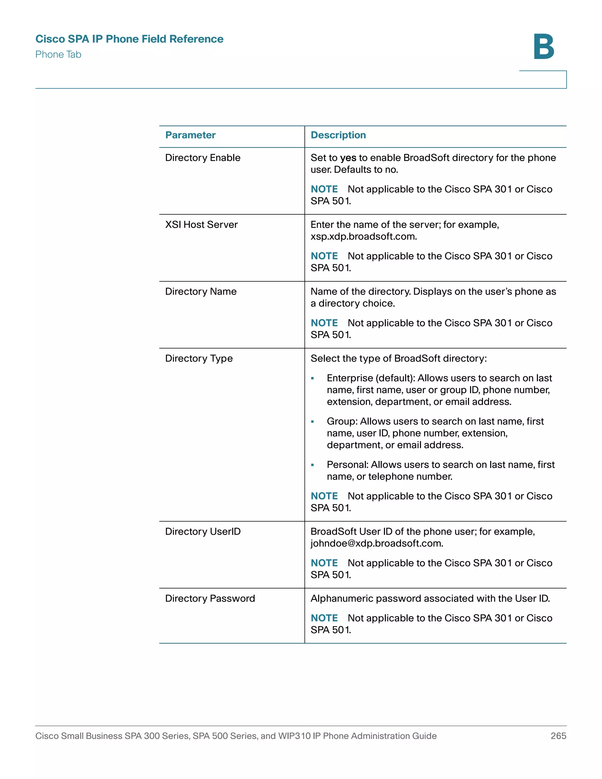
The Cisco SPA 300 Series and Cisco SPA 500 Series supports the BroadSoft
directory feature and synchronization of Do Not Disturb and Call Forward. The
following configuration fields are available:
Cisco Small Business SPA 300 Series, SPA 500 Series, and WIP310 IP Phone Administration Guide 264](https://image.slidesharecdn.com/ciscospa303-administrationguide-141015151631-conversion-gate02/75/Cisco-spa303-administration-guide-276-2048.jpg)
![Cisco SPA IP Phone Field Reference
Phone Tab
B
Parameter Description
LDAP Auth Method Select the authentication method that the LDAP
server requires. Choices are:
• None—No authentication is used between the
client and the server.
• Simple—The client sends its fully-qualified
domain name and password to the LDAP server.
May present security issues.
• Digest-MD5—The LDAP server sends
authentication options and a token to the client.
The client returns an encrypted response that is
decrypted and verified by the server.
LDAP Client DN Enter the distinguished name domain components
[dc] ; for example:
dc=cv2bu,dc=com
If using the default Active Directory schema
(Name(cn)->Users->Domain), an example of the
client DN follows:
cn="David Lee",dc=users,dc=cv2bu,dc=com
LDAP Username Enter the username for a credentialed user on the
LDAP server.
LDAP Password Enter the password for the LDAP username.
LDAP Search Base Specify a starting point in the directory tree from
which to search.
Separate domain components [dc] with a comma.
For example:
dc=cv2bu,dc=com
LDAP Last Name Filter This defines the search for surnames [sn], known as
last name in some parts of the world. For example,
sn:(sn=*$VALUE*). This search allows the provided
text to appear anywhere in a name, beginning,
middle, or end.
LDAP First Name Filter This defines the search for the common name [cn].
For example, cn:(cn=*$VALUE*). This search allows
the provided text to appear anywhere in a name,
beginning, middle, or end.
Cisco Small Business SPA 300 Series, SPA 500 Series, and WIP310 IP Phone Administration Guide 267](https://image.slidesharecdn.com/ciscospa303-administrationguide-141015151631-conversion-gate02/75/Cisco-spa303-administration-guide-279-2048.jpg)
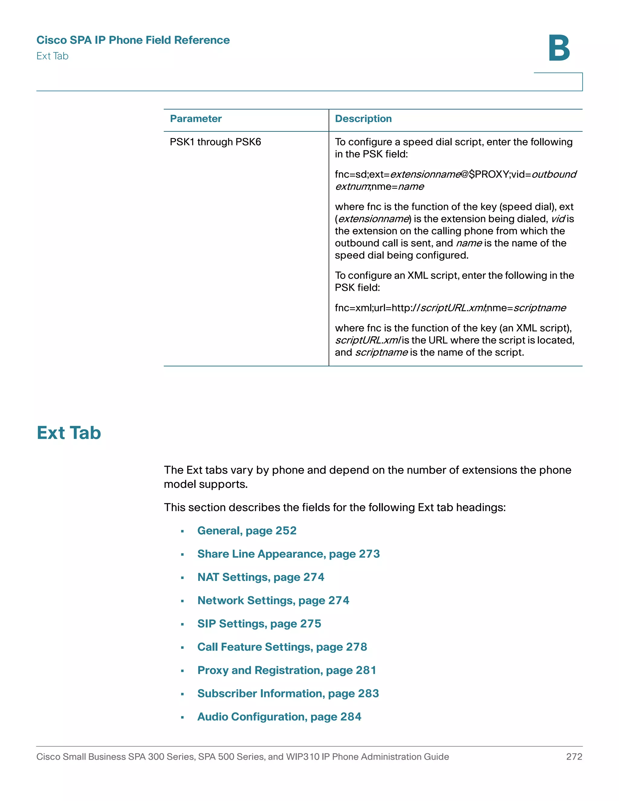
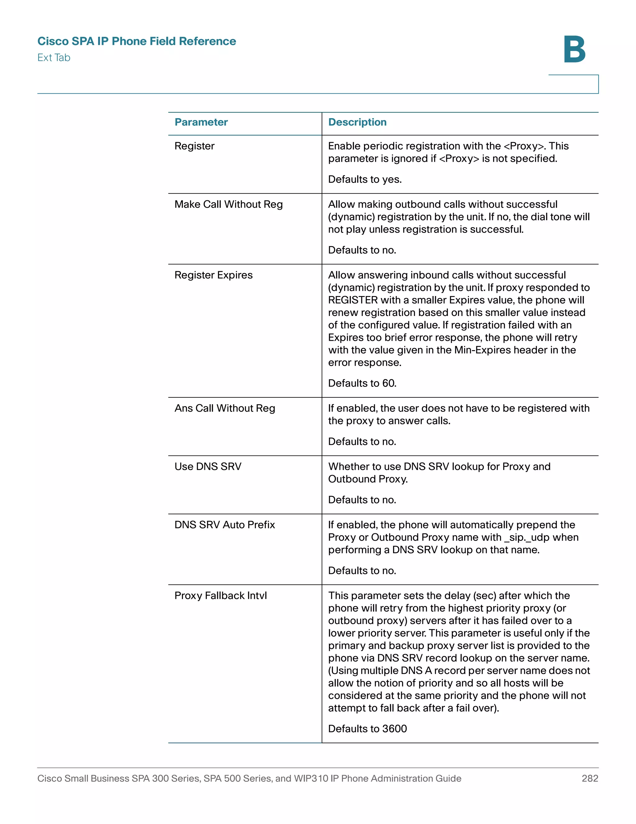
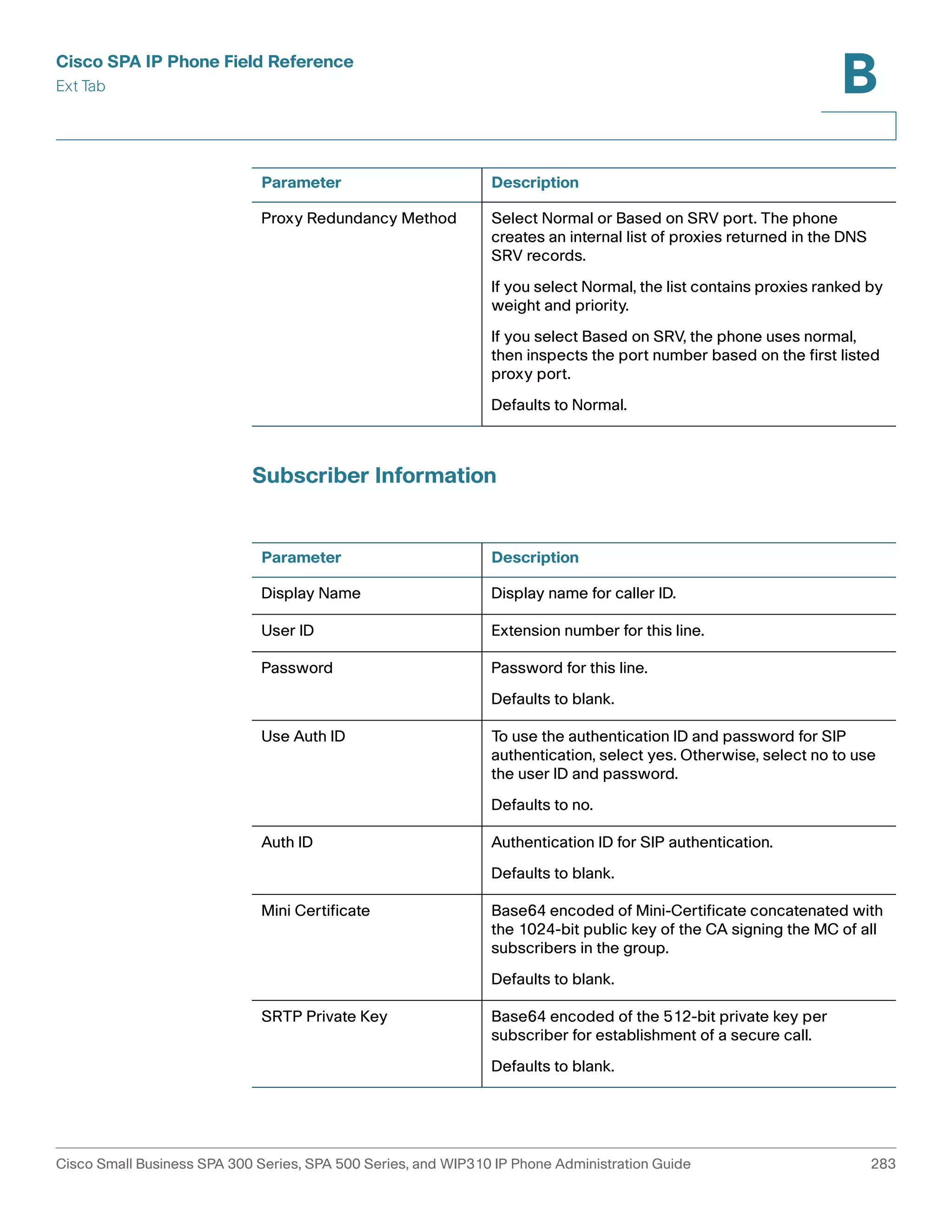
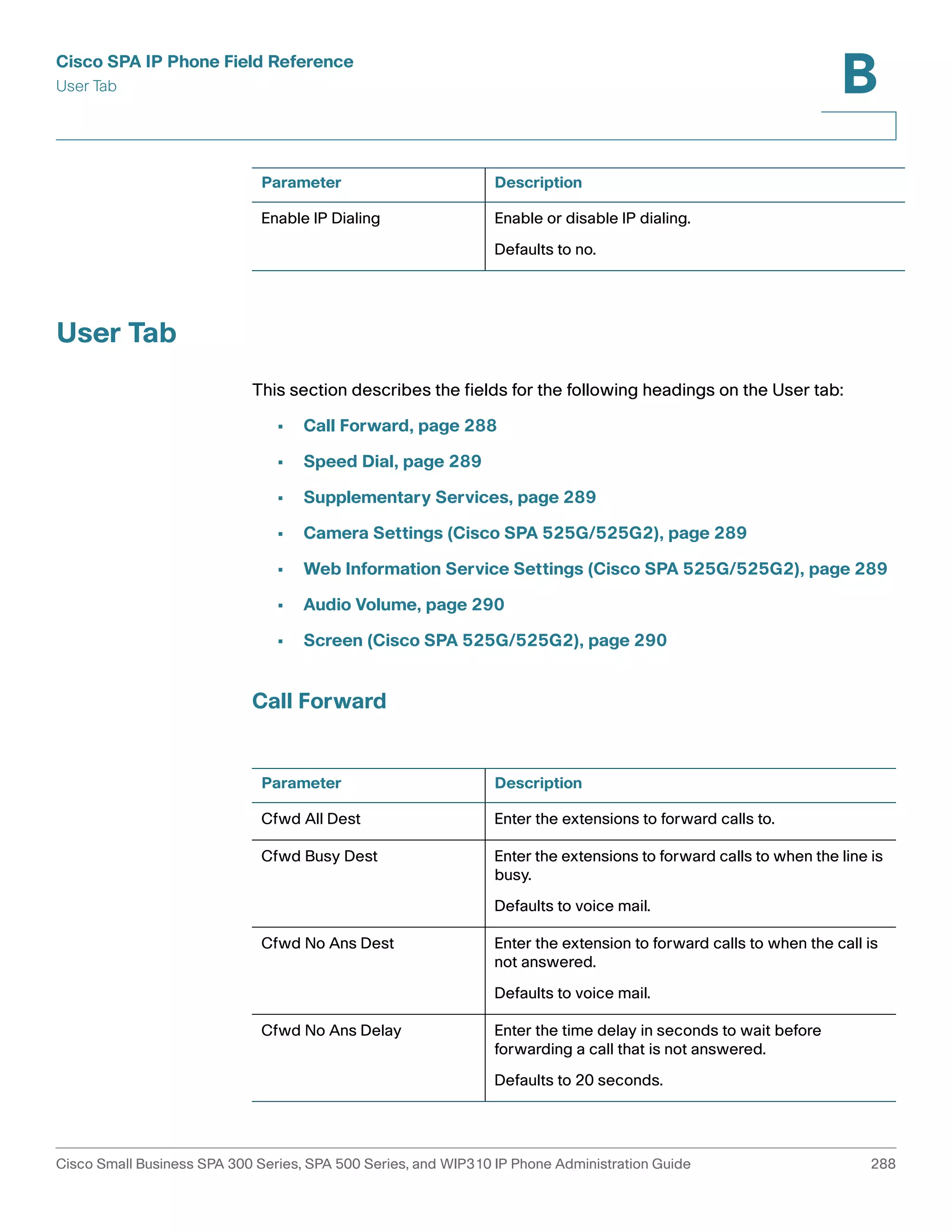
![Cisco SPA IP Phone Field Reference
Ext Tab
B
• Dial Plan, page 287
In a configuration profile, the Line parameters must be appended with the
appropriate numeral to indicate the line to which the setting applies. For example:
[1] to specify line one
[2] to specify line two
General
Line Enable: To enable this line for service, select yes. Otherwise, select no.
Defaults to yes.
Share Line Appearance
Parameter Description
Share Ext Indicates whether this extension is to be shared with
other stations or private. If the extension is not shared,
then a call appearance assigned to this extension is not
shared, regardless the setting of <Share Call
Appearance> for that call appearance. If the extension
is shared, then whether or not a call appearance
assigned to this extension is shared follows the setting
of <Share Call Appearance> for that call appearance.
The choices are shared or private.
Defaults to shared.
Shared User ID The user identified assigned to the shared line
appearance.
Subscription Expires Number of seconds before the SIP subscription
expires. Before the subscription expiration, the phone
gets NOTIFY messages from the SIP server on the
status of the shared phone extension. Defaults to 60
seconds.
Restrict MWI When enabled, the message waiting indicator lights
only for messages on private lines.
Monitor User ID (Cisco SPA
300 Series, Cisco SPA 500
Series)
This field is for future use.
Cisco Small Business SPA 300 Series, SPA 500 Series, and WIP310 IP Phone Administration Guide 273](https://image.slidesharecdn.com/ciscospa303-administrationguide-141015151631-conversion-gate02/75/Cisco-spa303-administration-guide-285-2048.jpg)

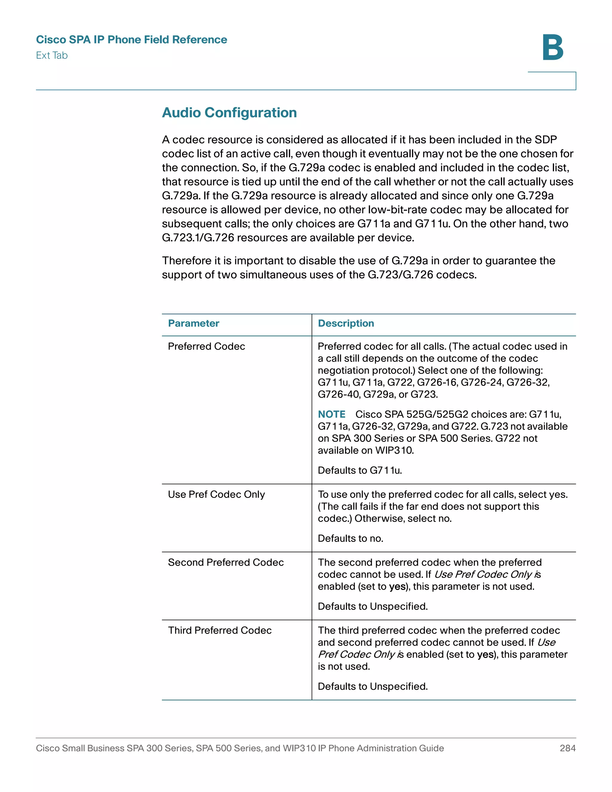
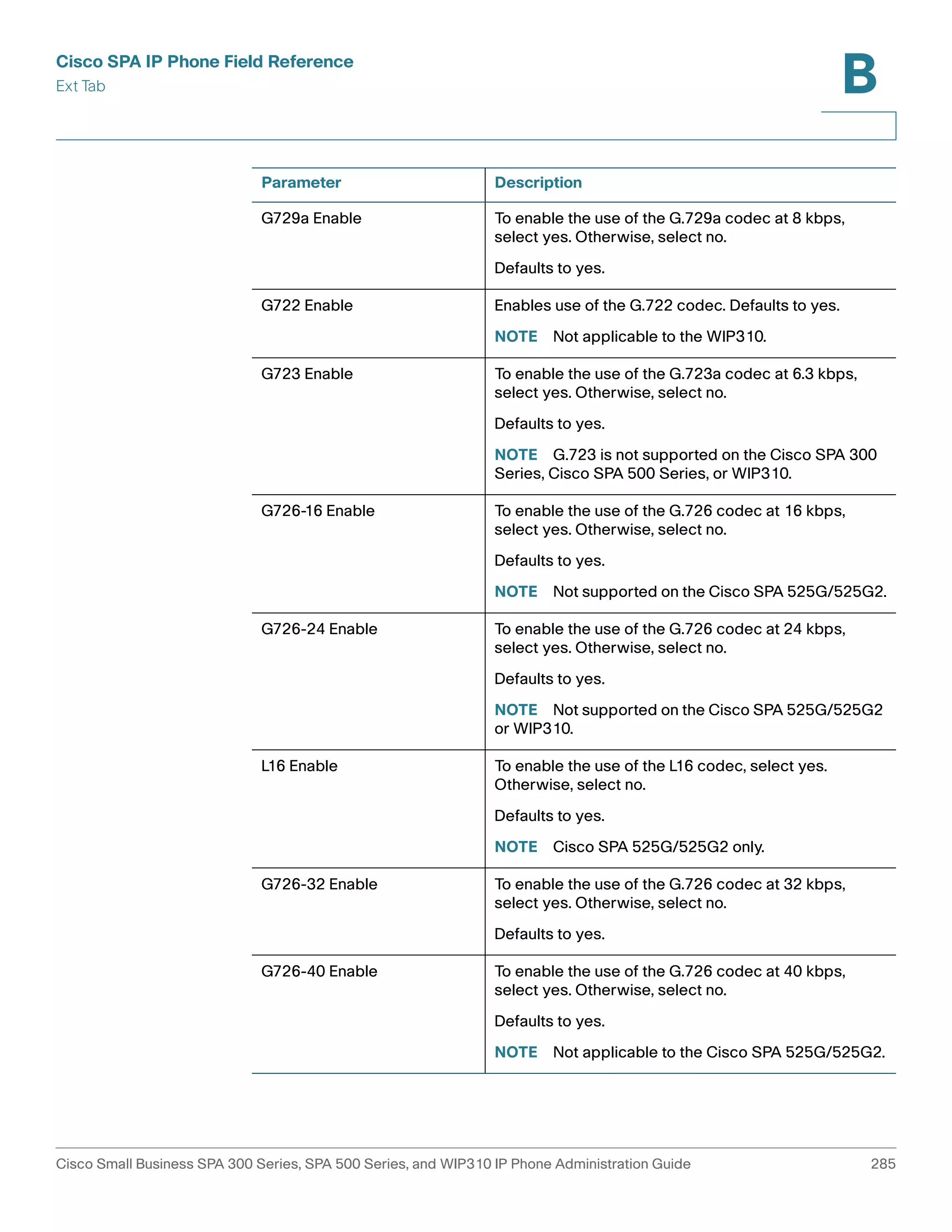
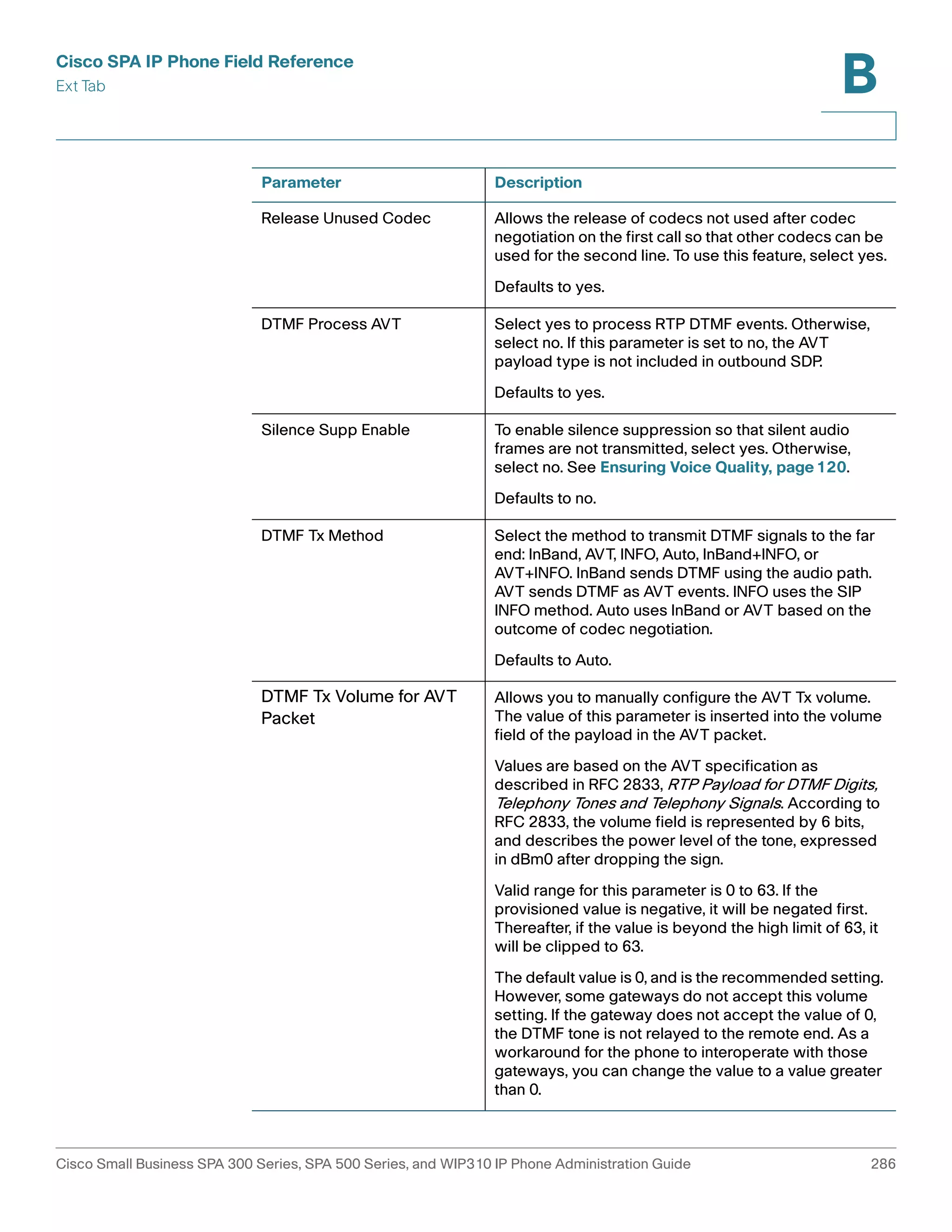
![Cisco SPA IP Phone Field Reference
Ext Tab
B
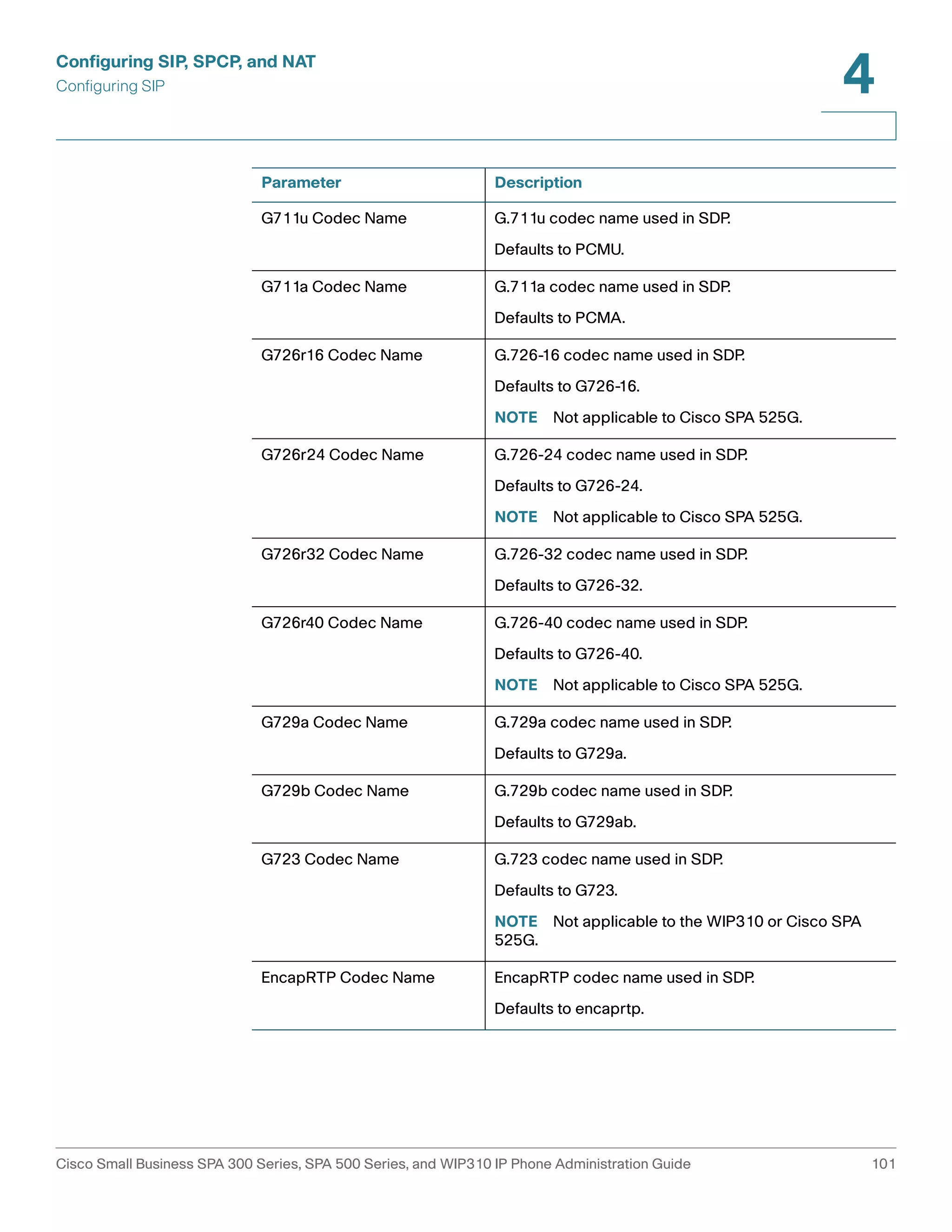
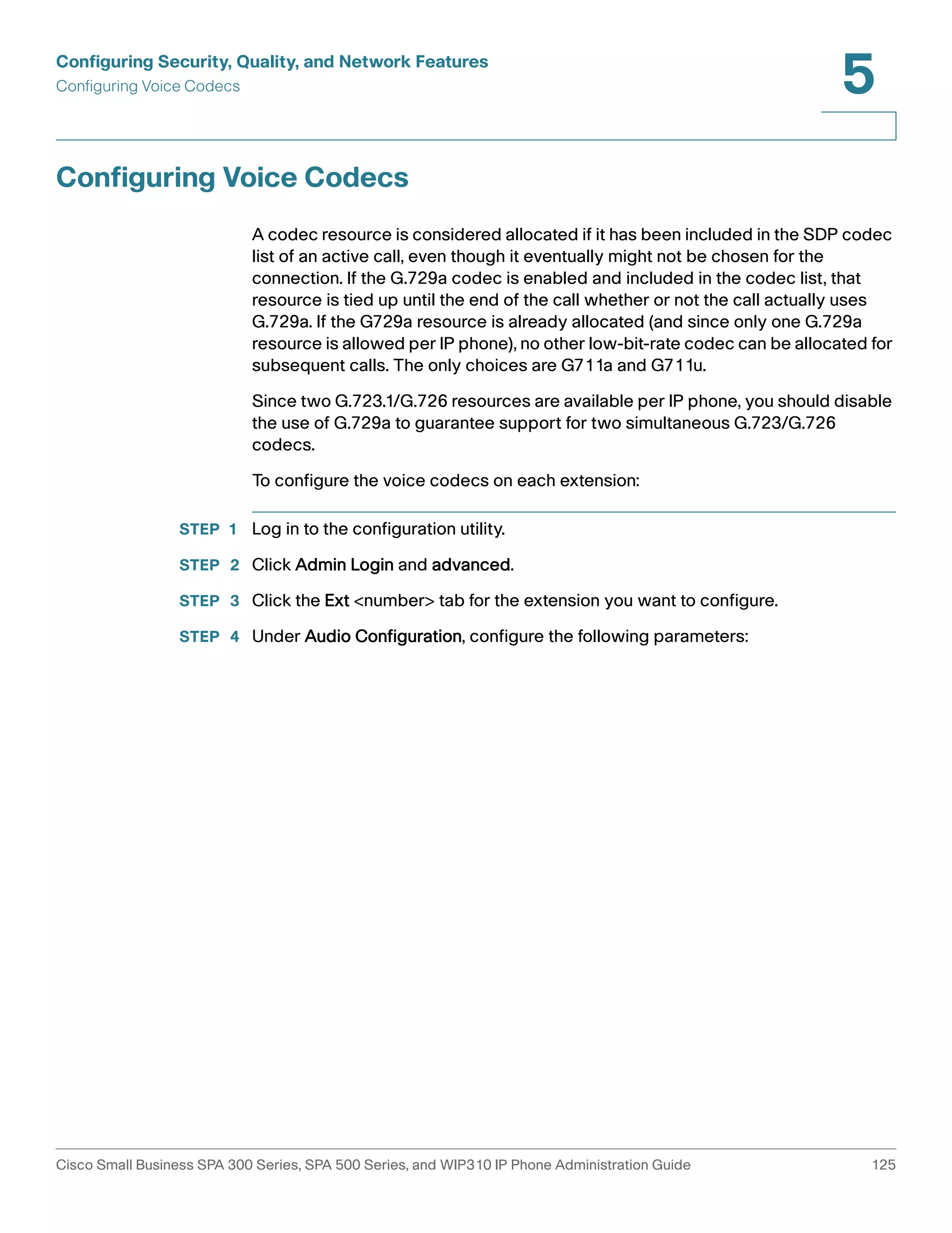
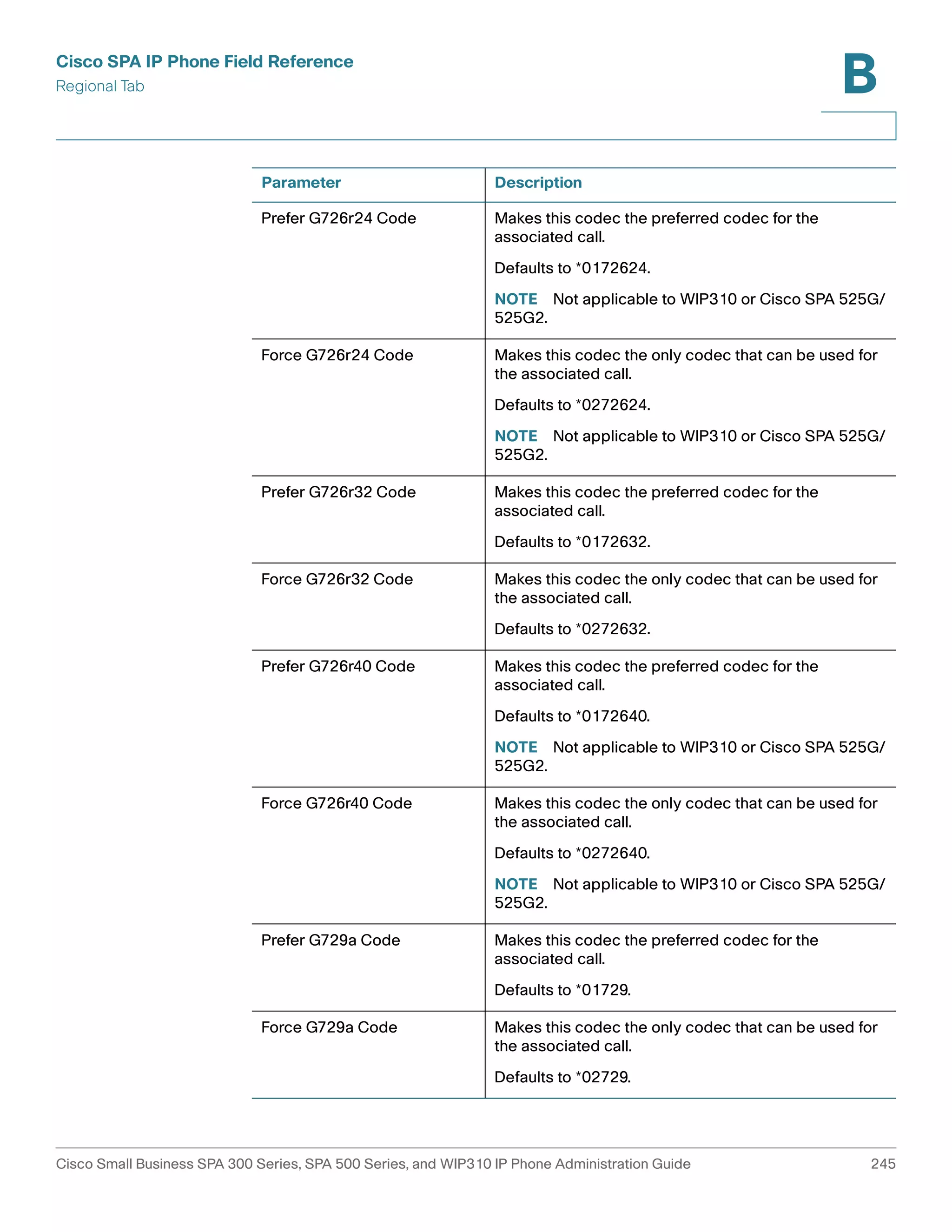
A codec resource is considered allocated if it has been included in the SDP codec
list of an active call, even though it eventually might not be chosen for the
connection. If the G.729a codec is enabled and included in the codec list, that
resource is tied up until the end of the call whether or not the call actually uses
G.729a. If the G729a resource is already allocated (and since only one G.729a
resource is allowed per phone), no other low-bit-rate codec can be allocated for
subsequent calls. The only choices are G711a and G711u.
Since two G.723.1/G.726 resources are available per IP phone, you should disable
the use of G.729a to guarantee support for two simultaneous G.723/G.726
codecs.
Dial Plan
The default dial plan script for each line is as follows: (*xx|[3469]11|0|00|[2-
9]xxxxxx|1xxx[2-9]xxxxxx|xxxxxxxxxxxx.).
Parameter Description
Dial Plan Dial plan script for this line.
The default is (<9:>xx.)
(*xx|[3469]11|0|00|[2-9]xxxxxx|1xxx[2-
9]xxxxxxS0|xxxxxxxxxxxx.)
The dial plan syntax is expanded in the Cisco SPA to
allow the designation of three parameters to be used
with a specific gateway:
• uid – the authentication user-id
• pwd – the authentication password
• nat – if this parameter is present, use NAT mapping
Each parameter is separated by a semi-colon (;).
Caller ID Map Inbound caller ID numbers can be mapped to a different
string. For example, a number that begins with
+44xxxxxx can be mapped to 0xxxxxx. This feature has
the same syntax as the Dial Plan parameter. With this
parameter, you can specify how to map a caller ID
number for display on screen and recorded into call
logs. (Not applicable to WIP310.)
Cisco Small Business SPA 300 Series, SPA 500 Series, and WIP310 IP Phone Administration Guide 287](https://image.slidesharecdn.com/ciscospa303-administrationguide-141015151631-conversion-gate02/75/Cisco-spa303-administration-guide-299-2048.jpg)


![[FOSS4G KOREA 2014] Introduce uDig](https://cdn.slidesharecdn.com/ss_thumbnails/foss4gintroduceudig-140828074849-phpapp01-thumbnail.jpg?width=640&height=640&fit=bounds)


![[DSC Europe 25] Dobrica Cosic - Savings by the Second: How Dynamic Pricing an...](https://cdn.slidesharecdn.com/ss_thumbnails/znp09f3smtqz3w2sq6wn-1-dobrica-cosic-savings-by-the-second-how-dynamic-pricing-and-smart-data-are-bu-251208151905-26e6f41e-thumbnail.jpg?width=640&height=640&fit=bounds)

![[DSC Europe 25] Goran Obradovic - The Rise of Sovereign AI: Building the Regi...](https://cdn.slidesharecdn.com/ss_thumbnails/7nw2xxixrxqdxvrb5wca-6-251205085714-ab09a2ac-thumbnail.jpg?width=640&height=640&fit=bounds)
![[DSC Europe 25] Kaja Kandare - LLM as a judge.pptx](https://cdn.slidesharecdn.com/ss_thumbnails/arxyccaxsdsd1ba99wjw-7-251212104007-2b4e3f64-thumbnail.jpg?width=640&height=640&fit=bounds)


![[DSC Europe 25] Branko Dzakula - From Defense to Attack: How AI Redefines Cyb...](https://cdn.slidesharecdn.com/ss_thumbnails/80bdzdxpr3ky2g0qvyk9-8-251211083048-ce5fc1ee-thumbnail.jpg?width=640&height=640&fit=bounds)
![[DSC Europe 25] Sara Polak - The Archaeology of Innovation: AI as the Next Cr...](https://cdn.slidesharecdn.com/ss_thumbnails/7ecbscdnt8mlcuqbd2ln-2-sara-polak-ai-creative-industries-251208152533-aa1fcf54-thumbnail.jpg?width=640&height=640&fit=bounds)

![[DSC Europe 25] Andy Cotgreave - Nothing is new in analytics.pptx](https://cdn.slidesharecdn.com/ss_thumbnails/mba4vzcurvoh5lfrd5zw-6-251205194645-341bbbbe-thumbnail.jpg?width=640&height=640&fit=bounds)
![[DSC Europe 25] Imai Jen-La Plante - The New Generation: AI and the Future of...](https://cdn.slidesharecdn.com/ss_thumbnails/kxi8t2l5rggivgcenyba-1-jenlaplante-dsc-251208152532-d1e076c2-thumbnail.jpg?width=640&height=640&fit=bounds)
![[DSC Europe 25] Milan Sekuloski - Data, Defence, and Development: Cybersecuri...](https://cdn.slidesharecdn.com/ss_thumbnails/dfrkwwx4qly6atqpbl4z-4-251209104645-c3d4b0ca-thumbnail.jpg?width=640&height=640&fit=bounds)
![[DSC Europe 25] Max Talanov - Non digital NNs.pptx](https://cdn.slidesharecdn.com/ss_thumbnails/wif8tr3gtua74qvtopke-non-digital-nns-251205090438-26b0eea6-thumbnail.jpg?width=640&height=640&fit=bounds)

![[DSC Europe 25] Bassam Maharmeh - Artificial Intelligence: Opportunities and ...](https://cdn.slidesharecdn.com/ss_thumbnails/thhfmr2fqpawzj7hsjpg-5-251211083048-2c23204f-thumbnail.jpg?width=640&height=640&fit=bounds)

