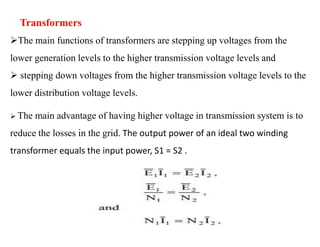
This document provides an overview of power systems, including their basic structure and components. It discusses:
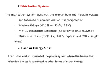
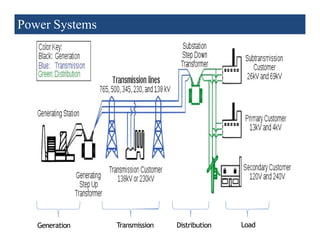
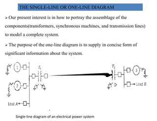
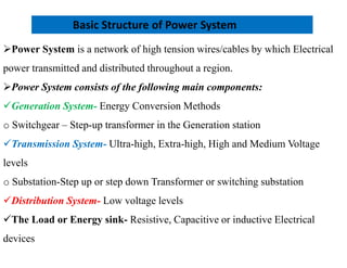
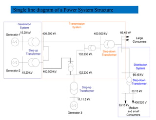
1) The main components of a power system include generation, transmission, distribution, and load. Generation involves converting energy into electricity through various methods.
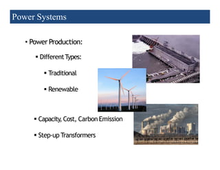
2) Transmission involves transporting bulk power over long distances at high voltages. Distribution delivers power to customers at lower voltages.
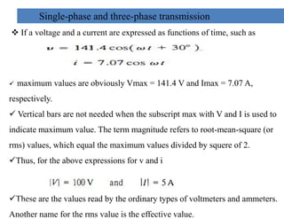
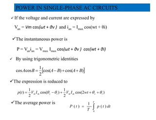
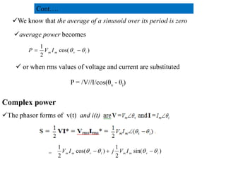
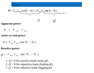
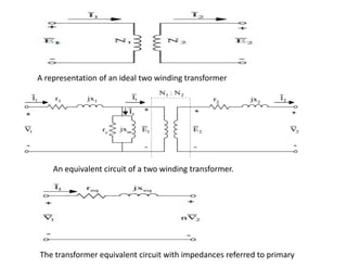
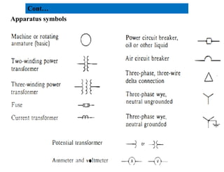
3) The document provides details on AC and DC transmission systems, as well as single and three-phase systems. It also discusses transformers, current transformers, and potential transformers.
![Existing System in Ethiopia
Generation [Source: EEP 2017]
• Hydro Power 4,068 MW
• Diesel Power 112 MW
• Geothermal Power 7 MW
Cont….
• Wind Power 324 MW
• Co-generation thermal 167 MW
Total 4678 MW
8
2/20/2023](https://image.slidesharecdn.com/ch1ppt1-240311072205-6dbf40e9/85/ch_introduction-to-power1-part-1_ppt-1-pdf-8-320.jpg)
![Existing Transmission Capacity in Ethiopia[EEP 2014]
2. Transmission Systems
This component of the power system transmits bulk electrical energy from
generation stations where it is produced to the main load centres. The
transmission system is composed of:
• Step-up and Step-down substations
• Transmission lines
Existing Transmission Capacity in Ethiopia[EEP 2014]
• 400 kV 686.7 km
• 230 kV 4222.95 km
• 132 kV 5033 km
• 66 kV 2234 km
• 45 kV 476 km
Total 12652.65 km
9
2/20/2023](https://image.slidesharecdn.com/ch1ppt1-240311072205-6dbf40e9/85/ch_introduction-to-power1-part-1_ppt-1-pdf-9-320.jpg)