ABSTRACT
The processes of the distributed system considered in this paper use loosely synchronized clocks. The paper describes a method of taking checkpoints by such processes in a truly distributed manner, that is, in the absence of a global checkpoint coordinator. The constituent processes take checkpoints according to their
own clocks at predetermined checkpoint instants. A global consistent set of such asynchronous checkpoints needs to be formed to avoid the domino effect. This is achieved by adding suitable information to the existing clock synchronization messages looking at which the processes synchronize their checkpoints to form a global consistent checkpoint. Communication in this system is synchronous, so, processes may be blocked for communication at checkpointing instants. The blocked processes save the state they were in just before being blocked. It is shown here that the set of such i-th checkpoints is consistent and hence the rollback required by the system in case of failure is only up to the last saved state.
KEYWORDS
Fault tolerance, Checkpointing, Rollback recovery, Synchronized clock,Clock synchronization message
PDF LINK: https://www.airccse.org/journal/iju/papers/0410iju5.pdf
VOLUME LINK: https://www.airccse.org/journal/iju/vol1.html
MORE INFO: https://www.airccse.org/journal/iju/index.html
![10.5121/iju.2010.1205 64
S. Neogy1
A. Sinha1
P. K. Das2
1
Department of Computer Science & Engg., Jadavpur University, India
sarmisthaneogy@gmail.com
2
Faculty of Engg. & Tech., Mody Institute of Technology & Science, India
ABSTRACT
The processes of the distributed system considered in this paper use loosely synchronized clocks. The paper
describes a method of taking checkpoints by such processes in a truly distributed manner, that is, in the
absence of a global checkpoint coordinator. The constituent processes take checkpoints according to their
own clocks at predetermined checkpoint instants. A global consistent set of such asynchronous checkpoints
needs to be formed to avoid the domino effect. This is achieved by adding suitable information to the
existing clock synchronization messages looking at which the processes synchronize their checkpoints to
form a global consistent checkpoint. Communication in this system is synchronous, so, processes may be
blocked for communication at checkpointing instants. The blocked processes save the state they were in just
before being blocked. It is shown here that the set of such i-th checkpoints is consistent and hence the
rollback required by the system in case of failure is only up to the last saved state.
KEYWORDS
Fault tolerance, Checkpointing, Rollback recovery, Synchronized clock,Clock synchronization message
1. INTRODUCTION
The distributed system considered here consists of several processes executing on different nodes
that communicate with each other via synchronous message passing. Each process has its own
logical clock as explained by Lamport in [4]. It is assumed that the system uses a fault-tolerant
hardware platform as described in Neogy [9]. A synchronization layer guarantees the
synchronization of the individual clocks by sending suitable messages (henceforth referred to as
clock synchronization message) at the end of each resynchronization interval as shown by Sinha
[15]. There exists a constant Dmax such that in the kth resynchronization interval (k≥0) for all
correct clocks i and j, if the logical clocks of processes Pi and Pj be denoted by Ci
k
and Cj
k
, then as
given in Srikanth [16],
| Ci
k
(t) - Cj
k
(t)| ≤ Dmax (1)
One of the attractive approaches for providing fault tolerance to such distributed systems is the
checkpoint/rollback recovery mechanism mentioned in Koo [3]. As is widely known,
checkpointing is the method of periodically recording the state of a system in stable storage. Thus,
a checkpoint will include the computational messages transferred by different processes. Any such
periodically saved state is called a checkpoint of the process. As observed by Manivannan [5], a
global state is a set of individual process states, one per process. The state contains a snapshot at
some instant during the execution of a process. The major drawback of implementing rollback
recovery technique is the domino effect dealt with by Tsai [19].](https://image.slidesharecdn.com/0410iju5-250514150325-ebbca6e8/85/Checkpointing-with-Synchronized-Clocks-in-Distributed-Systems-1-320.jpg)
![10.5121/iju.2010.1205 64
S. Neogy1
A. Sinha1
P. K. Das2
1
Department of Computer Science & Engg., Jadavpur University, India
sarmisthaneogy@gmail.com
2
Faculty of Engg. & Tech., Mody Institute of Technology & Science, India
ABSTRACT
The processes of the distributed system considered in this paper use loosely synchronized clocks. The paper
describes a method of taking checkpoints by such processes in a truly distributed manner, that is, in the
absence of a global checkpoint coordinator. The constituent processes take checkpoints according to their
own clocks at predetermined checkpoint instants. A global consistent set of such asynchronous checkpoints
needs to be formed to avoid the domino effect. This is achieved by adding suitable information to the
existing clock synchronization messages looking at which the processes synchronize their checkpoints to
form a global consistent checkpoint. Communication in this system is synchronous, so, processes may be
blocked for communication at checkpointing instants. The blocked processes save the state they were in just
before being blocked. It is shown here that the set of such i-th checkpoints is consistent and hence the
rollback required by the system in case of failure is only up to the last saved state.
KEYWORDS
Fault tolerance, Checkpointing, Rollback recovery, Synchronized clock,Clock synchronization message
1. INTRODUCTION
The distributed system considered here consists of several processes executing on different nodes
that communicate with each other via synchronous message passing. Each process has its own
logical clock as explained by Lamport in [4]. It is assumed that the system uses a fault-tolerant
hardware platform as described in Neogy [9]. A synchronization layer guarantees the
synchronization of the individual clocks by sending suitable messages (henceforth referred to as
clock synchronization message) at the end of each resynchronization interval as shown by Sinha
[15]. There exists a constant Dmax such that in the kth resynchronization interval (k≥0) for all
correct clocks i and j, if the logical clocks of processes Pi and Pj be denoted by Ci
k
and Cj
k
, then as
given in Srikanth [16],
| Ci
k
(t) - Cj
k
(t)| ≤ Dmax (1)
One of the attractive approaches for providing fault tolerance to such distributed systems is the
checkpoint/rollback recovery mechanism mentioned in Koo [3]. As is widely known,
checkpointing is the method of periodically recording the state of a system in stable storage. Thus,
a checkpoint will include the computational messages transferred by different processes. Any such
periodically saved state is called a checkpoint of the process. As observed by Manivannan [5], a
global state is a set of individual process states, one per process. The state contains a snapshot at
some instant during the execution of a process. The major drawback of implementing rollback
recovery technique is the domino effect dealt with by Tsai [19].](https://image.slidesharecdn.com/0410iju5-250514150325-ebbca6e8/75/Checkpointing-with-Synchronized-Clocks-in-Distributed-Systems-1-2048.jpg)
![65
In a truly distributed system, where there is no central checkpoint coordinator, each process takes
its own checkpoint individually. However, at any given point of time it has to be ensured that the
set of most recent checkpoints taken by the processes provides a consistent picture of the system.
The constituent processes of our system take individual (local) checkpoints at predetermined time
instants according to their own logical clock. The set of all such local k-th checkpoints (k ≥ 0)
form the global k-th checkpoint. Since communication in the system is only through messages, it
is to be guaranteed that no message gets lost in case a failure of any system component occurs.
This implies that some sort of synchronization must exist among the set of otherwise
asynchronous local checkpoints. The easiest, as also the much-practised means adopted in such
situation is the introduction of special message as shown in Kalaiselvi [2]. But messages meant for
checkpointing purposes only increase system overhead. To avoid this we have utilized the clock
synchronization message itself for checking the consistency of the set of local checkpoints. The
additional information required for this is appended at the end of the clock synchronization
message. This work shows that any global checkpoint taken in the above-mentioned fashion in our
system is consistent and the system has to roll back only to the last saved state in case of a failure
as described in Neogy [7]. The rest of the paper is organized as follows. Section 2 gives the basic
ideas about consistent checkpoints. Section 3 discusses some related works. Section 4 describes
our system model, Section 5 discusses in detail the checkpointing algorithm with study of various
inconsistent cases along with a proof of correctness of the algorithm. Section 6 presents the
simulation results and Section 7 draws concluding remarks.
2. BASIC CONCEPTS AND IDEAS
In the present discussion we regard consistency of a checkpoint, according to Chandy [1] and Tsai
[18], as the constraint that if a sender 'S' sends a message 'm' before it has taken its i-th checkpoint,
then message 'm' must be received by a receiver 'R' before the receiver has taken its i-th
checkpoint. A message will be termed missing in the i-th global checkpoint if its sending is
recorded by S but its receipt is not recorded by R. Again, if the sending of a message is not
recorded whereas its receipt is recorded then it is termed an orphan as described in Tong [17]. If a
system can ensure that there is no missing or orphan message in the i-th checkpoint, then the set of
all the i-th checkpoints taken by its constituent processes is bound to be consistent. Maintaining
consistency is necessary to avoid the domino effect during rollback recovery in case any process
fails after taking its i-th checkpoint. If the set of the i-th checkpoints can be proved to be
consistent, then in case of failure the system has to roll back only up to the i-th checkpoint.
It is assumed here that a constituent process may be either blocked for communication or
executing or ready for execution. Since communication is assumed to be synchronous, processes
get blocked during communication. The synchronous transfer of a message m between two
processes Pi and Pj involves three significant events E1(m), E2(m) and E3(m) as described below
(Figure 1) where Ti(m) is real time instant. Since processes in this system execute asynchronously,
so, any one of the communication partners may try to execute its communication statement earlier
than the other while the other may not have arrived at that communication statement yet. So, one
of the partners has to wait for the other.
Event E1(m): At T1(m) the process executing its communication statement earlier begins wait
for message m to be sent or received.
Event E2(m): At T2(m) the transfer of message m actually commences. At this point, the process
that reaches its communication statement later has executed it.
Event E3(m): At T3(m) the transfer of m terminates.](https://image.slidesharecdn.com/0410iju5-250514150325-ebbca6e8/85/Checkpointing-with-Synchronized-Clocks-in-Distributed-Systems-2-320.jpg)
![66
Pi T1(m) T2(m) T3(m)
Pj T1(m) T2(m) T3(m)
Figure 1: Significant time instants in the synchronous message passing between Pi and Pj
Blocking interval: The blocking interval [Tx(m), T3(m)] where x = 1 for the process executing its
communication statement earlier and x = 2 for the process executing its communication statement
later. For instance, if Pi executes its communication statement earlier, then Pi is blocked in the
interval [T1(m), T3(m)] while Pj is blocked in the interval [T2(m), T3(m)].
It is assumed here that the state recorded for a blocked process is the state it was in just before it
blocked even if its checkpointing instant occurs during its blocking period. When a particular
process is ‘ready’ or ‘running’ and a checkpointing instant occurs according to its logical clock
then its checkpoint is taken immediately. After taking the checkpoint it however does not resume
its task but just freezes (that is, it stops executing) till the end of the current clock
resynchronization interval. The idea behind the freezing is that the processes would first check
their corresponding checkpoints for consistency and then proceed further. During this check a
process may find out that there is a possibility of having missing/orphan message(s) in the
concerned checkpointing interval that has given rise to inconsistency. Since logical clocks of the
processes do not match exactly with each other there may be a skew between any two clocks
whose upper bound is Dmax as already mentioned in (1). The checkpointing instants will also suffer
from that skew thus giving rise to the possibility of inconsistency. The list of computational
messages exchanged in the current checkpoint interval (checkpoint interval is the time between
two consecutive checkpoints) is appended to the clock synchronization message thus avoiding the
overhead of sending separate messages for consistency checking. These ideas have been
incorporated in designing the present checkpointing algorithm. The algorithm described in Section
5 provides corrective measure that removes any inconsistency. An alternative method of taking
checkpoints by a blocked process is described in Neogy [7] where the blocked process takes
checkpoint after it unblocks even if the checkpointing instant had already occurred.
3. RELATED WORKS
Unlike the approach that should exist in a distributed system Kalaiselvi [2] have a checkpoint
coordinator that matches the message log it gets from all the processes at each checkpointing time.
The present work does not have a checkpoint coordinator. Due to disparity in speed or congestion
in the network, a message belonging to the (i+1)th checkpointing interval may reach the receiver
who has not yet taken its i-th checkpoint. Such a message is not acknowledged in Tong [17] and
the sender retransmits it. In Neves [10] a sender is prevented from sending for a certain time. In
Neves [11] unacknowledged messages are made a part of the next checkpoint. The very design of
our system prevents the occurrence of such a message. Distributed systems that use the recovery
block approach of Randell [14] and have a common time base may estimate a time by which the
participating processes would take acceptance tests. These estimated instants form the pseudo
recovery point times as described in Ramanathan [13]. The disadvantages of such a scheme are
that the fast processes have to wait for slow processes and there is a need for time-out to ensure
that fault in some process does not permanently hold up other non-faulty processes. In the present
work any process takes checkpoints according to its own logical clock and does not have to wait
for others.](https://image.slidesharecdn.com/0410iju5-250514150325-ebbca6e8/85/Checkpointing-with-Synchronized-Clocks-in-Distributed-Systems-3-320.jpg)
![67
The work presented in [20] tries to minimize the number of checkpoints that are not “useful”. A
checkpoint is “useful” if it belongs to some consistent global checkpoint. It can be proved that a
checkpoint is “useful” if and only if it is not involved in any zigzag cycle. This seems to incur a
substantial overhead. The authors do not give any measure of this overhead. On the contrary, our
algorithm does not incur this overhead as we do not need to detect zigzag cycles.
Furthermore, Xu and Netzer’s work does not attempt to eliminate rollback propagation. It does not
guarantee that every checkpoint will belong to some consistent checkpoint. Instead, it reduces
rollback propagation to less than one checkpoint interval. In contrast, our algorithm always
ensures that every checkpoint is globally consistent. We assume a synchronous communication
model and there are no “in-transit” messages. Rollback propagation is irrelevant in our algorithm
and rollback is always to the last (globally consistent) checkpoint.
The work presented in [21] defines a function ~ . Two sets of checkpoints R and S are related R
~ S iff there is a zigzag path from some member of R to some member of S. The authors show
how a consistent set of checkpoints can be obtained by starting from a set S satisfying S ~⁄ S.
In our algorithm, this is not an issue since every global checkpoint is consistent and only the last
one needs to be saved.
The work presented in [22] is a communication-induced checkpointing protocol that ensures the
RDT (Rollback Dependency Trackability) property. Each process maintains a Transitive
Dependency Vector TDV of integers. It also maintains a Boolean array simple and a Boolean
matrix causal. When a message m is sent, the variable tdv, causal and simple are piggybacked on
the message. On receiving ‘m’, the destination process updates its own variables and takes a
forced checkpoint if required. The “per-message overhead” of this algorithm can be significant for
fine-grain applications, i.e., applications which communicate frequently. In contrast, our algorithm
does not involve any “per-message overhead”. The overhead that we incur is only on a per-
checkpoint basis. That overhead is (i) the bookkeeping of the number of messages exchanged
between different processes during the last checkpointing interval. This information is
piggybacked on clock synchronization messages that are periodically exchanged among processes;
and (ii) the freezing time, i.e., the time for which a process remains suspended after taking a
checkpoint.
The work in [23] presents a more formal and generalized framework in which the works of [22]
exists. The author defines Elimentary-Prime-Simple-Causal-Message Z-paths (EPSCM). It is then
established that EPSCM property is RDT-compliant and that this property can not be implied by
any other RDT-compliant property with respect to the set of Z-paths. A protocol based on minimal
EPSCM-path subset has also been presented. This again suffers from the per-message overhead
already discussed.
4. SYSTEM MODEL
Let us now consider a system of ‘n’ processes, P0, P1, …. Pn-1 each of which takes individual
checkpoints at predetermined instants of its logical clock. Let these instants be denoted by Ck
i
,
where i denotes the checkpoint index (i≥0) and k denotes the process id (0≤k≤n-1). Let the
checkpoints be denoted as the initial checkpoint CPk
0
, first checkpoint CPk
1
, second checkpoint
CPk
2
and so on. The initial checkpoint will be taken when the system is initialized. Let us now
state our assumptions regarding the system:
Logical clocks of any two processes are synchronized periodically by exchanging messages [15,
16] (referred to as clock synchronization messages) and are at most Dmax apart from each other
[Section1]
Communication is synchronous and performs the steps mentioned in Section 2 (figure 1) where
Tk(m) denotes instant of time for a message m throughout this paper:
Each process maintains information about messages sent and received during each checkpointing
interval by storing the (sender id/ receiver id, message id) pair.](https://image.slidesharecdn.com/0410iju5-250514150325-ebbca6e8/85/Checkpointing-with-Synchronized-Clocks-in-Distributed-Systems-4-320.jpg)
![68
Checking of consistency between a pair of kth checkpoints CPi
k
and CPj
k
of processes Pi and Pj
respectively involve checking of whether message/s recorded sent by one (Pi or Pj) in its
corresponding checkpoint is/are recorded received by the other (Pj or Pi) in its corresponding
checkpoint and vice versa.
Processes blocked in communication are able to take checkpoint if checkpointing instant t occurs
during that interval that is, Tx(m) < t < Tz(m). The state recorded is the one the process was in
prior to Tx(m) .
Assumption 5 above tells that if a process is in the midst of receiving (at time instant t where
Tx(m) < t < T3(m)) while its checkpointing instant occurs, then the checkpoint will not include the
receiving buffer. Also, if a process is in the midst of sending (at time instant t where Tx(m) < t <
T3(m)) while its checkpointing instant occurs, then the checkpoint will not include the sending
buffer. Communication is taken care of by the existing protocols for synchronous communication.
5. THE CHECKPOINTING ALGORITHM
Before formally presenting the algorithm we describe its working by explaining various situations
under which a process Pi may have to take its checkpoint.
We have used the Clock Synchronization Algorithm of Srikanth [16]. Let the clock
resynchronization period be P. Resynchronization is done periodically and the resynchronization
interval is designated K (=1,2,,….). Let ‘f’ be the maximum number of faulty nodes in the system.
When the logical clock of a node reaches K.., it broadcasts a “Ready-K” message to all other
nodes, signifying that it is ready to resynchronize. This message is “signed” to provide Byzantine
Resilience. On receiving such a messagem every node relays it to the other nodes. When a node
receives (f+1) “Ready-K” messages originated from distinct nodes, it resynchronizes its logical
clock to KP+ where is a constant. It then increments K, the resynchronization interval number.
This algorithm ensures that the logical clocks of all non-faulty nodes are synchronized to within a
predefined constant Dmax. The obvious constraints on Dmax are the maximum clock drift and the
maximum node-to-node message transit time (single-hop) tdel. When any process resynchronizes
its clock, every other process is guaranteed to do so within a time bound Dmax [Axiom 7]. For a
special Dmax, the constant is given by Axiom 2. The upper and lower bounds on P are specified
by Axiom 3 and 4 respectively. The formal specification of the physical clock drift is given by
Axiom 6. The axioms are described in Section 5.3.
From Srikanth [16] we know that a process expects its kth resynchronization at time kP on its
logical clock where P is the logical time between resynchronizations. Resynchronization takes
place by setting the clock of the process to kP+α where α is a constant. In the present work we
have chosen the predetermined checkpointing instants at kP+0.5P+α for specific values of k.
5.1 WORKING OF THE ALGORITHM
Here we describe in details how a process Pi would take its kth checkpoint according to the present
algorithm. Each process maintains a list of computational messages in the form of mlist(Pi, k)
which is essentially a list of message transfers in which Pi participated during the k-th
checkpointing interval. So, mlist(Pi, k) = msent(Pi, k) ∧ mrecd(Pi, k) where msent(Pi, k) and
mrecd(Pi, k) denote respectively the list of messages sent and received by Pi during the k-th
checkpointing interval. Let us denote by sender(m) the process that sent message m and by
receiver(m) the process that receives message m. Let the logical clock of Pi determine the
checkpoint instant for taking k-th checkpoint. The take_ckpt() algorithm is invoked periodically
by the system when the logical clock reaches predefined values [Rule 1, Section 5.3 ]. It is a time-](https://image.slidesharecdn.com/0410iju5-250514150325-ebbca6e8/85/Checkpointing-with-Synchronized-Clocks-in-Distributed-Systems-5-320.jpg)
![69
triggered system process independent of the application process. At that time Pi may be in one of
the following states:
Case 1: Executing computation: Pi is interrupted and immediately saves its current state. This
represents step 2.1 of take_ckpt(). Rather than resuming its computation Pi freezes, that is, stops its
activities and waits for the time-out of the current resynchronization interval (step 2.2). At the end
of the interval Pi sends out messages for resynchronizing logical clock to other processes in the
system as elaborated in Sinha [15] and Srikanth [16]. Pi appends information of computation
messages that it has sent and received (according to assumption 3 in Section 4) in the current
checkpointing interval to the message of clock synchronization. Pi now resumes whatever it was
doing before the kth checkpointing instant occurred.
Case 2: In the midst of communication: Since communication is assumed to be synchronous
(Section 2) Pi is either blocked or transferring data. The checkpoint state-saving can proceed
concurrently without interrupting the communication. In this case, the state saved is the one just
prior to the beginning of execution of communication statement. However, when Pi finishes
communication it has to be suspended, i.e., it cannot reschedule its next activity until the following
clock synchronization instant.
If Pi remains blocked in communication when the following clock synchronization occurs, the
system still works consistently. The information that needs to be exchanged on occurrence of
event1 (time-out of current clock synchronization interval) is exchanged in the background by the
system without any involvement on the part of Pi. The message transfer in which Pi participates is
NOT recorded either at the sender-end or at the receiver-end since the state saved is the one at the
beginning of the communication. Since communication is synchronous, Pi’s partner cannot record
the (termination of) message transfer until Pi does so.
Pi checks each such information for possible existence of any one of the following:
Case 2a: A message has been recorded to be received by some Pj (in CPj
k
) whose sender is Pi
though Pi’s local checkpoint (CPi
k
) does not record the send of the same message, that is,
∃m : mrecd(Pj, k) and m ∉ ((msent(Pi, k)) ∧ (sender(m) = Pi))
In this case Pi’s checkpoint is modified to record the corresponding send. Then Pi resumes its next
task.
Case 2b: A message has been recorded to be sent by Pj (in CPj
k
) whose destination is Pi though
Pi’s local checkpoint (CPi
k
) does not record the receipt of the same message, that is,
∃m : msent(Pj, k) and m ∉ ((mrecd(Pi, k)) ∧ (sender(m) = Pj))
In this case Pi takes another checkpoint called a forced checkpoint to include the corresponding
receipt. Then Pi resumes its task.
Before going into the algorithm let us describe the procedures, events and date structures used in
the algorithm for checkpointing in a system of n processes. The kth checkpoint in process Pi is
denoted by CPi
k
.
Events:
event1: Time-out of current clock synchronization interval
event2: Receiving by Pi of clock resynchronization messages along with other information
(sp_mess) (described later) from Pj where 0≤j≤n-1 and j≠i
Procedures:
save_state(): procedure that writes current process state in stable storage, that is it writes
checkpoint CPi
k
save_block_state(): procedure that writes in stable storage the state of a blocked process prior to
blocking, that is it writes checkpoint CPi
k
.
save_mod_state(): procedure that accesses CPi
k
from stable storage and appends updated
mess_sent_own[] array (defined below)
wait(event): procedure that suspends current activities until event occurs
send(source, destination, message): procedure for sending message in synchronous mode
receive(source, message): procedure for receiving messages in synchronous mode](https://image.slidesharecdn.com/0410iju5-250514150325-ebbca6e8/85/Checkpointing-with-Synchronized-Clocks-in-Distributed-Systems-6-320.jpg)
![70
Data structures:
mess_sent_own[]: an n-element vector maintained by each process Pi that indicates the number
of messages Pi has sent to the process with vector index as process id during the current
checkpointing interval, that is, mess_sent_own[j] = x means that Pi has sent x messages in the
current checkpointing interval to Pj.
mess_recd_own[]: an n-element vector maintained by each process Pi that indicates the number of
messages Pi has received from the process with vector index as process id during the current
checkpointing interval, that is, mess_recd_own[j] = x means that Pi has received x messages in the
current checkpointing interval from Pj.
clock_resynch_mess: message for clock resynchronization as described in Sinha [15] and Srikanth
[16]
sp_message: special message carrying mess_sent_own[] and mess_recd_own[] with
clock_resynch_mess
mess_sent_other[i][]: This array is compiled by Pi after Pi receives mess_sent_own[] of each Pj
from all Pj (0≤j≤n-1 and j≠i) in the following way:
for(all j = 0,1,2,..,n-1 and j≠i)
mess_sent_other[i][j] = mess_sent_own[j]
mess_recd_other[i][]: This array is compiled by Pi after Pi receives mess_recd_own[] of each Pj
from all Pj (0≤j≤n-1 and j≠i) in the following way:
for(all j = 0,1,2,..,n-1 and j≠i)
mess_recd_other[i][j] = mess_recd_own[j]
flag_new, flag_mod: boolean variables which when set indicate that a new checkpoint has to be
taken or the current checkpoint has to be modified respectively
All array elements are initialized to –1 and all boolean variables to false at the beginning of each
checkpointing interval.
Symbols:
: concatenation
Algorithm: take_ckpt()
(For any process Pi whose kth checkpointing instant Ci
k
has occurred)
flag_new, flag_mod = false
If Pi is executing computation, then
Pi calls save_state()
Pi calls wait(event1)
For (all j = 0,1,2,…,n-1 and j ≠ i)
sp_message = clock_resynch_mess mess_sent_own[] mess_recd_own[]
send(Pi, Pj, sp_message)
3. else // Pi is blocked in communication //
Pi calls save_block_state() from its blocked state
Pi calls wait(event1)
For (all j = 0,1,2,…,n-1 and j ≠ i)
sp_message = clock_resynch_mess mess_sent_own[] mess_recd_own[]
send(Pi, Pj, sp_message)
Pi calls wait(event2)
For (all j = 0,1,2,..,n-1 and j≠i)
if (mess_sent_own[j] < mess_recd_other[i][j])
mess_sent_own[j] := mess_recd_other[i][j]
flag_mod = true
if (mess_recd_own[j] < mess_sent_other[i][j])
flag_new = true
break](https://image.slidesharecdn.com/0410iju5-250514150325-ebbca6e8/85/Checkpointing-with-Synchronized-Clocks-in-Distributed-Systems-7-320.jpg)
![72
Case i: Let Pi be faster than Pj as depicted in figure 4. The kth checkpointing instant Ci
k
occurs
when Pi is blocked on event e2ij. This is shown as shaded box in figure 4. Let Pi be the sender in
e2ij. Pi does not record the send of e2ij in CPi
k
since the event has not yet finished. Inconsistency
will occur if Pj records the receipt of e2ij in CPj
k
. Since Pj has finished receiving when its
checkpointing instant Cj
k
occurs, so it records e2ij in CPj
k
leading to inconsistency. It is evident
from the figure that Pj has advanced during the interval (time of occurrence of e2ij, CPj
k
). At xi Pi
notes the inconsistency (step 3.5.1 of the algorithm). Since Pi has not executed anything during the
interval (CPi
k
, xi) (step 3.2 of algorithm) so, the algorithm (steps 3.7, 3.7.1) modifies the CPi
k
only
to the effect that it now records the send of e2ij and thus CPi
k
and CPj
k
become mutually consistent.
Case ii: Let Pi be faster than Pj as depicted in figure 5. The k-th checkpointing instant Ci
k
occurs
when Pi is blocked on event e2ij. This is shown as shaded box in figure 5. Let Pi be the receiver in
e2ij. Pi does not record the receipt of e2ij in CPi
k
since the event has not yet finished. But,
checkpointing instant Cj
k
occurs in Pj after Pj has finished “sending”. So, Pj records event e2ij in
CPj
k
. This leads to inconsistency. Pi notes the inconsistency at xi (step 3.5.2 of the algorithm) and
takes a forced checkpoint CPi
k’
(steps 3.6, 3.6.1. of the algorithm) to become mutually consistent
with Pi.
Case 3: Pi and Pj are both blocked during their respective checkpointing instants
Pi CPi
k-1
CPi
k
xi Pi CPi
k-1
CPi
k
xi CPi
k’
e1ij e2ij e1ij e2im
Pj CPj
k-1
CPj
k
Pj CPj
k-1
CPj
k
e1ij e2ij xj e1ij e2jh xj
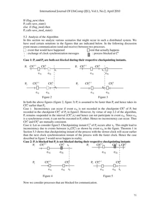
Figure 6 Figure 7
Case 3a: Let Pi and Pj be blocked over the same communication event e2ij. Hence according to the
algorithm none of them would record the communication event in their respective checkpoints
CPi
k
and CPj
k
. Hence no inconsistency would arise.
Case 3b: Let Pi and Pj be blocked over different communication events e2im and e2jh. Hence
according to the algorithm none of them would record the corresponding communication events in
their respective checkpoints CPi
k
and CPj
k
. If the communication partners Pm (of Pi) and Ph (of Pj)
record the corresponding events in their respective checkpoints CPm
k
and CPh
k
, then inconsistency
would be dealt with as already described in Case2. Otherwise no inconsistency would arise.
5.3. PROOF OF CORRECTNESS
Axiom 1: The clock drift rate ρ satisfies 0<ρ<1 by Srikanth [16].
Axiom2: For a user-selected maximum clock deviation Dmax, and maximum message transit time
tdel, the clock correction α has a lower bound given by Srikanth [16]
α ≥ [(1+ρ)Dmax + tdel] * (1+ρ)
Axiom 3: The lower bound on the clock resynchronization interval P is given by Srikanth [16]
P ≥ dmin(1+ρ) + α
Axiom 4: The upper bound on P is (Srikanth [16])
P ≤ [((Dmax – dmin(1+ρ)) / dr) - tdel ] / (1+ρ)
Axiom 5: The maximum drift rate dr between clocks is (Srikanth [16])
dr = (1+ρ) – (1+ρ)-1](https://image.slidesharecdn.com/0410iju5-250514150325-ebbca6e8/85/Checkpointing-with-Synchronized-Clocks-in-Distributed-Systems-9-320.jpg)
![73
Axiom 6: A straight line envelope of the logical clock of a process has a slope m satisfying
(1+ρ)-1
≤ m ≤ (1+ρ)
Axiom 7: The maximum time difference between resynchronization of two processes is
dmin = tdel > 0 (Srikanth[15])
Rule 1: The logical clock time of checkpointing for a process x is chosen by the following rule
Cx
k+1
(Tx
k
) = (k+0.5)P +α
where Tx
k
is the corresponding real time.
This rule is obviously a design issue. It sets the checkpointing instant halfway (on the logical clock
axis) during the (k+1)th resynchronization period (k = 1,2,……). However, a process takes
checkpoint for some specified values of k.
Lemma 1: (i) dr < 2ρ and (ii) (1+ρ)-1
> (1-ρ)
Lemma 2: If z >0 then (a) x>y xz>yz and (b) x>y x/z>y/z
Lemma 3: If x > y >0, then 1/x<1/y
Lemma 4: dr > 0
Lemma 5: The product of positive monotonic increasing functions is a positive monotonic
increasing function.
Lemma 6: The function fn(ρ) = ρn
where n is a positive integer is monotone increasing.
Lemma 7: The sum of two monotone increasing functions is monotone increasing.
Lemma 8: The function e(ρ) = kρn
where k is a positive constant and n is a positive integer is
monotone increasing.
Lemma 9: If x ≥ xmin and y ≤ ymax then xmin – ymax > 0 (x- y > 0)
Lemma 10: If 0<x≤xmax and y≥ymin>0 then x/y ≤ xmax/ymin
Lemma 11: For any two processes Ps and Pr, the respective kth checkpointing instants Ts
k
and Tr
k
during the kth resynchronization interval are selected by RULE-1. Without loss of generality, we
assume that Pr has the faster clock. Then Tr
c
– Ts
k
= (P-α)(1/m1 – 0.5/m2) – (t2 – t1) where Tr
c
is the
next clock resynchronization time of Pr.
Proof: Without loss of generality, we assume that Pr has the faster clock, that is,
m1>m2 and t1<t2
Figure 8 shows the logical clocks Cr
k+1
and Cs
k+1
of Pr and Ps during the (k+1)th resynchronization
interval. They have slopes m1 and m2. By Rule-1,
Cr
k+1
(Tr
k
) = Cs
k+1
(Ts
k
) = (k+0.5)P+0.5α (11.1)
Since (Tr
c
, Cr
k+1
(Tr
c
)) and (t1, Cr
k+1
(t1)) are two points on straight line Cr
k+1
having slope m1,
[Cr
k+1
(Tr
c
) - Cr
k+1
(t1)] / (Tr
c
– t1) = m1 (11.2)
By Srikanth and Toueg’s algorithm [15],
Cr
k+1
(Tr
c
) = (k+1)P (11.3a)
Cs
k+1
(Ts
c
) = (k+1)P (11.3b)
and Cr
k+1
(t1) = kP+α (11.4a)
Cs
k+1
(t2) = kP+α (11.4b)
Substituting (11.3a) and (11.4a) in (11.2) we get,
Tr
c
– t1 = (P-α)/m1 (11.5)](https://image.slidesharecdn.com/0410iju5-250514150325-ebbca6e8/85/Checkpointing-with-Synchronized-Clocks-in-Distributed-Systems-10-320.jpg)
![74
(k+1)P
Logical time
slope=m1 slope=m2
(k+0.5)P+0.5α
Cr
k+1
Cs
k+1
kP+α
t1 t2 Tr
k
Ts
k
Tr
c
Ts
c
Real time
Figure 8. Checkpointing and resynchronization instants of Pr and Ps
during the (k+1)th resynchronization interval
Similarly, since (Ts
k
, Cs
k+1
(Ts
k
)) and (t2, Cs
k+1
(t2)) are two points on straight line Cs
k+1
having slope
m2, [Cs
k+1
(Ts
k
) – Cs
k+1
(t2)] / (Ts
k
– t2) = m2 (11.6)
Substituting (11.1) and (11.4b) in (11.6)
Ts
k
– t2 = 0.5(P-α)/m2 (11.7)
From (11.5) and (11.7), we get
(Tr
c
– t1) – (Ts
k
– t2) = (P-α)(1/m1 – 0.5/m2) (11.8)
(Tr
c
– Ts
k
)+(t2 - t1) = (P-α)(1/m1 – 0.5/m2)
(Tr
c
– Ts
k
) = (P-α)(1/m1 – 0.5/m2) - (t2 - t1) (11.9)
Lemma 12: If (i) (1/m1 – 0.5/m2 > (t2 – t1)/(P – )) and
(ii) t1 < t2
then 1/m1 – 0.5/m2 > 0
Proof:
1. dmin > 0 [by Axiom 7]
2. > 0 [by Axiom 1]
3. 1+ > 0 [by 2]
4. dmin(1+ ) > 0 [by (1), (3) and Lemma 2]
5. (P – ) > dmin(1+ ) [by Axiom 3]
6. (P – ) > 0 [by (4) and (5)]
7. t2 – t1 > 0 [by Hypothesis (ii)]
8. (t2 – t1)/(P – ) > 0 [by (6), (7) and Lemma 2]
9. 1/m1 – 0.5/m2 > (t2 – t1)/(P – ) [by Hypothesis (i)]](https://image.slidesharecdn.com/0410iju5-250514150325-ebbca6e8/85/Checkpointing-with-Synchronized-Clocks-in-Distributed-Systems-11-320.jpg)
![75
10. 1/m1 – 0.5/m2 > 0 [by (8) and (9)]
End Proof
Lemma 13: If ρ < (√2 - 1) then (1+ρ)-1
- 0.5(1+ρ) > 0
Proof:
1. ρ < (√2 - 1) [by Hypothesis]
2. > 0 [by Axiom 1]
3. ρ > -(√2 - 1) [by (2)]
4. ρ + (√2 - 1) > 0 [by (3)]
5. (ρ - √2 + 1) < 0 [by (1)]
6. (ρ + √2 + 1) (ρ - √2 + 1) < 0 [by (4), (5) and Lemma 2]
7. (ρ + 1)2
- (√2)2
< 0 [by (6)]
8. 2 - (ρ + 1)2
> 0 by (7)]
9. 2(1 + ρ)-1
– (1 + ρ) > 0 [by (8), Lemma 2 and Axiom 1]
10. (1 + ρ)-1
– 0.5(1 + ρ) > 0 [by (9) and Lemma 2 since 0.5 > 0]
End Proof
Lemma 14: If ρ < (√2 - 1) then (1/m1 – 0.5/m2) > 0
Proof:
1. ρ < (√2 - 1) [by Hypothesis]
2. (1 + ρ)-1
– 0.5(1 + ρ) > 0 [by (1) and Lemma 13]
3. 1/m1 ≥ (1+ρ)-1
[by Axiom 6]
4. 1/m2 ≤ (1+ρ) [by Axiom 6]
5. 0.5/m2 ≤ 0.5(1+ρ) [by (4) and Lemma 2 since 0.5 > 0]
6. (1 + ρ)-1
– 0.5(1 + ρ) > 0 (1/m1 – 0.5/m2 > 0) [by (3), (5) and Lemma 9]
7. (1/m1 – 0.5/m2 > 0) [by (2) and (6)]
End Proof
Lemma 15: If (i) ρ < (√2 - 1) and
(ii) P – > (t2 – t1) / (1/m1 – 0.5/m2)
then Tr
c
– Ts
k
> 0
Proof:
1. 1/m1 – 0.5/m2 > 0 [by Hypothesis (i) and Lemma 14]
2. Tr
c
– Ts
k
= (P – ) (1/m1 – 0.5/m2) - (t2 – t1) [by Lemma 11]
3. P – > (t2 – t1) / (1/m1 – 0.5/m2) [by Hypothesis (ii)]
4. (P – )(1/m1 – 0.5/m2) > (t2 – t1) [by (3), (1) and Lemma 2]
5. Tr
c
– Ts
k
> 0 [by (4) and (2)]
End Proof
Lemma 16: If (i) ρ < (√2 - 1) and (ii) t2 > t1
then (t2 – t1) / (1/m1 – 0.5/m2) dmin / (1 + ρ)-1
– 0.5(1 + ρ)
Proof:
1. t2 – t 1 > 0 [by Hypothesis (ii)]
2. 0 < t2 – t1 dmin [by (1) and Axiom 7]
3. (1 + ρ)-1
– 0.5(1 + ρ) > 0 [by Hypothesis (i) and Lemma 13]
4. 1/m1 ≥ (1+ρ)-1
[by Axiom 6]
5. 1/m2 ≤ (1+ρ) [by Axiom 6]
6. 0.5/m2 ≤ 0.5(1+ρ) [by (5) and Lemma 2 since 0.5 > 0]
7. (1 + ρ)-1
– 0.5(1 + ρ) (1/m1 – 0.5/m2) [by (4), (6) and Lemma 9(b)]
8. (1/m1 – 0.5/m2) (1 + ρ)-1
– 0.5(1 + ρ) > 0 [by (7) and (3)]
9. (t2 – t1) / (1/m1 – 0.5/m2) dmin / (1 + ρ)-1
– 0.5(1 + ρ) [by (2), (8) and Lemma 10]
End Proof
Lemma 17: dmin / (1 + ρ)-1
– 0.5(1 + ρ) = 2dmin / (1 + ρ)-1
– dr](https://image.slidesharecdn.com/0410iju5-250514150325-ebbca6e8/85/Checkpointing-with-Synchronized-Clocks-in-Distributed-Systems-12-320.jpg)
![76
Proof: dmin / (1 + ρ)-1
– 0.5(1 + ρ)
= 2dmin / 2(1 + ρ)-1
– (1 + ρ)
= 2dmin / ((1 + ρ)-1
+ (1 + ρ)-1
– (1 + ρ))
= 2dmin / ((1 + ρ)-1
– ( (1 + ρ) - (1 + ρ)-1
)))
= 2dmin / ((1 + ρ)-1
– dr) [by Axiom 5]
End Proof
Lemma 18: If (i) (P-α) > 2dmin / ((1 + ρ)-1
– dr)
(ii) ρ < (√2 - 1) and
t2 > t1
then Tr
c
> Ts
k
Proof:
1. (P-α) > 2dmin / ((1 + ρ)-1
– dr) [by Hypothesis]
2. 2dmin / ((1 + ρ)-1
– dr) = dmin / ((1 + ρ)-1
– 0.5 (1 + ρ)) [by Lemma 17]
3. (P-α) > dmin / ((1 + ρ)-1
– 0.5 (1 + ρ)) [by (1) and (2)]
4. (t2 – t1) / (1/m1 – 0.5/m2) dmin / (1 + ρ)-1
– 0.5(1 + ρ) [by Hypothesis (ii), (iii) and Lemma 16]
5. (P-α) > (t2 – t1) / (1/m1 – 0.5/m2) [by (3) and (4)]
6. Tr
c
- Ts
k
> 0 [by (5), Hypothesis (ii) and Lemma 15]
End Proof
Lemma 19: If ρ < (√2 - 1) then 2dmin / ((1 + ρ)-1
– dr) > dmin(1 + ρ)
Proof:
ρ > 0 [by Axiom 1]
1+ρ > 1 [by (1)]
[(1+ρ) -1] > 0 [by (2)]
[(1+ρ) +1] > 1 + 1 [by (2)]
[(1+ρ) +1] > 0 [by (4) and since 2 > 0]
6. [(1+ρ)-1][(1+ρ)+1] > 0 [by (3),s (5) and Lemma 2]
7. (1+ρ)2
-1 > 0 [by (6)]
8. (1+ρ)2
- 2 + 1> 0 [by (7)]
9. 2 - (1+ρ)2
< 1 [by (8)]
10. ρ < (√2 - 1) [by Hypothesis]
11. 1 + ρ < √2 [by (10)]
12. 1 + ρ - √2 < 0 [by (11)]
13. 1 + ρ + √2 > 0 [by Axiom 1]
14. [(1+ρ) - √2][(1+ρ) + √2]< 0 [by (12), (13) and Lemma 2]
15. (1+ρ)2
- 2 < 0 [by (14)]
16. 2 - (1+ρ)2
> 0 [by (15)]
17. 0 < 2 - (1+ρ)2
< 1 [by (9) and (16)]
18. 1 < 1 / [2 - (1+ρ)2
] [by (17) and Lemma 3]
19. 2 < 2 / [2 - (1+ρ)2
] [by (18) and Lemma 2 since 2 > 0]
20. 2 - 1 < 2 / [2 - (1+ρ)2
] - 1 [by (19)]
21. 2 / [2 - (1+ρ)2
] – 1 > 0 [by (20) since 1 > 0]
22. 2dmin / ((1 + ρ)-1
– dr) = 2dmin(1 + ρ) / (1 – [(1 + ρ)2
– 1]) [by Axiom 5]
23. 2dmin / ((1 + ρ)-1
– dr) - dmin(1 + ρ) = dmin(1 + ρ)[2 / (1 – [(1 + ρ)2
– 1]) – 1]
= dmin(1 + ρ)[2 / [(2 – (1 + ρ)2
)] – 1] [by (22)]
24. dmin(1 + ρ) > 0 [since dmin > 0 by Axiom7 and ρ > 0 by Axiom 1]
25. dmin(1 + ρ)[2 / [(2 – (1 + ρ)2
)] – 1] > 0 [by (24), (21) and Lemma 2]
26. 2dmin / ((1 + ρ)-1
– dr) - dmin(1 + ρ) > 0 [by (23) and (25)]](https://image.slidesharecdn.com/0410iju5-250514150325-ebbca6e8/85/Checkpointing-with-Synchronized-Clocks-in-Distributed-Systems-13-320.jpg)
![77
27. 2dmin / ((1 + ρ)-1
– dr) > dmin(1 + ρ) [by (26)]
End Proof
Definition 1. k3 dmin(1+ρ)
Definition 2. k37 2dmin / [(1+ρ)-1
– dr]
P P-α
α
α
α-k37 = 0
π
π
π
π B C P=π
π
π
π
A
P-α
α
α
α-k3 = 0
k37
k3
α
α
α
α
(α
α
α
α2,0) (k2,0)
α
α
α
α=α
α
α
α2
Figure 9: Finding the feasible values of P and α
In figure 9, we plot the design parameters P and α. For convenience, we define,
Definition 3. π ≡ [[[Dmax-dmin(1+ρ)]/dr] – tdel] / (1+ρ)
Definition 4. α2 [(1+ρ)Dmax+tdel] (1+ρ)
Definition 5. k2 π - k37
Definition 6. Z dmin/dr + tdel/(1+ ) + tdel(1+ )
Definition 7. W 2dmin / [dr(1+ )] + dmin/dr + tdel/(1+ ) +2 tdel(1+ )
Lemma 20: If Dmax[1 / dr(1+ ) - (1+ )2
] > 2dmin / ((1 + ρ)-1
– dr) + Z
Then k2 > 2 and conversely.
Proof:
Let k2 > 2
⇔ π -k37 > 2
⇔ π -k37 > [(1+ρ)Dmax+tdel] (1+ρ) [by Definition 4]
⇔ π > 2dmin / [(1+ρ)-1
– dr] + [(1+ρ)Dmax+tdel] (1+ρ) [by Definition 2]
⇔ [[[Dmax-dmin(1+ρ)]/dr] – tdel] / (1+ρ) > 2dmin / [(1+ρ)-1
– dr] + [(1+ρ)Dmax+tdel] (1+ρ)
[by Definition 2]
⇔ Dmax[[1/(1+ρ)dr] – (1+ρ)2
] > dmin/dr + tdel/(1+ρ)+2dmin/[(1+ρ)-1
– dr] + tdel(1+ρ)
⇔ Dmax[[1/(1+ρ)dr] – (1+ρ)2
] > 2dmin/[(1+ρ)-1
– dr] + Z [by Definition 6]
End Proof
Lemma 21: If ρ < 0.2054687
then dr(2 + ) - (1+ρ)-1
< 0
Proof: Let dr(2 + ) - (1+ρ)-1
< 0 (L21.1)
⇔ dr(2 + )(1+ρ) – 1 < 0 [by Lemma 2(i) since 1+ >0 by Axiom 1]
⇔ (2 + )[(1+ρ)2
– 1] - 1 < 0 [by Axiom 5]
⇔ (2 + )[(1+ρ)+1][(1+ρ)-1] - 1 < 0 [by Axiom 5]](https://image.slidesharecdn.com/0410iju5-250514150325-ebbca6e8/85/Checkpointing-with-Synchronized-Clocks-in-Distributed-Systems-14-320.jpg)
![78
⇔ (2 + )(2+ρ) – 1 < 0
⇔ 3
+ 4 2
+ 4ρ < 1 (L21.2)
Let f( ) = 3
+ 4 2
+ 4ρ …… (L21.3)
By iterative techniques, we find that
f(0.205664) = 1.000546 > 1 (L21.4)
and f(0.2054687) = 0.9994189 < 1
By Lemma 8 each of the terms on the right hand side of [L21.3] is monotone increasing. It
follows, therefore, from [L21.4] that
ρ < 0.2054687 f( ) < 1 3
+ 4 2
+ 4ρ < 1 [by L21.3]
dr(2 + ) - (1+ρ)-1
< 0 [by L21.1 and L21.2]
End Proof
Lemma 22: If ρ < 0.2054687
then dr(1 + ) < (1+ρ)-1
- dr
Proof: ρ < 0.2054687
dr(2 + ) - (1+ρ)-1
< 0 [by Lemma 21]
dr(1 + ) + dr - (1+ρ)-1
< 0
dr(1 + ) < (1+ρ)-1
– dr
End Proof
Lemma 23: If ρ < 0.2054687
then 2dmin / ((1 + ρ)-1
– dr) < 2dmin / dr(1 + ρ)
Proof:
dr > 0 [by Lemma 4] (L23.1)
> 0 [by Axiom 1] (L23.2)
So, 1 + > 0 (L23.3)
By (L23.1) and (L23.3),
dr(1 + ) > 0 [Product of positives is positive]
ρ < 0.2054687 (L23.4)
dr(1+ ) < (1+ )-1
– dr [by Lemma 22]
0 < dr(1+ ) < (1+ )-1
– dr [by L23.4]
1 / [(1+ )-1
– dr] < 1 / dr(1+ ) [by Lemma 3]
2dmin / [(1+ )-1
– dr] < 2dmin / dr(1+ )[by Lemma 2(i) since dmin>0 by Axiom 7]
End Proof
Lemma 24: If (i) ρ < 0.2054687 and
(ii) Dmax[[1/dr(1+ )] – (1+ )2
] > 2dmin / dr(1+ ) + Z
then Dmax[[1/dr(1+ )] – (1+ )2
] > 2dmin / [(1+ )-1
– dr] + Z
Proof:
(1) 2dmin / [(1+ )-1
– dr] < 2dmin / dr(1+ ) [by Hypothesis (i) and Lemma 23]
(2) 2dmin / [(1+ )-1
– dr] + Z < 2dmin / dr(1+ ) + Z [by (1)]
(3) 2dmin / dr(1+ ) + Z < Dmax[1/dr(1+ ) - (1+ )2
] [by Hypothesis (ii)]
(4) Dmax[1/dr(1+ ) - (1+ )2
] > 2dmin / [(1+ )-1
– dr] + Z [by (2) and (3)]
End Proof
Lemma 25: If (i) ρ < 0.2054687 and
(ii) Dmax[[1/dr(1+ρ)] – (1+ρ)2
] > tdel/dr(1+ρ)[2ρ3
+6ρ2
+6ρ+4]
then Dmax[[1/(1+ρ)dr] – (1+ρ)2
] > 2dmin/[(1+ρ)-1
- dr] + Z
Proof: We will try to apply Lemma 24 to prove this proposition.
We focus our attention to the expression 2dmin / dr(1+ ) + Z which forms the right hand side of the
antecedent of Lemma 24.
2dmin / dr(1+ ) + Z (L25.1)
= 2dmin / dr(1+ ) + dmin/dr + tdel/(1+ ) + tdel(1+ ) [by Definition 6]](https://image.slidesharecdn.com/0410iju5-250514150325-ebbca6e8/85/Checkpointing-with-Synchronized-Clocks-in-Distributed-Systems-15-320.jpg)
![79
= [2dmin + dmin(1+ ) + tdeldr + tdel(1+ )2
dr] / dr(1+ )
< [2dmin + dmin(1+ ) + tdel(1+ ) + tdel(1+ )2
dr] / dr(1+ ) [since dr=(1+ )-(1+ )-1
and
(1+ )-1
> 0 and (1+ ) > dr]
< [2dmin + dmin(1+ ) + tdel(1+ ) + 2tdel(1+ )2
dr] / dr(1+ ) (L25.2) [since tdel(1+ )2
dr > 0]
Now, 2dmin + dmin(1+ ) + tdel(1+ ) + 2tdel(1+ )2
dr
= tdel[2+(1+ )+(1+ )+2(1+ )2
dr][by Axiom 7]
= tdel[2 3
+6 2
+6 +4] (L25.3) [by Axiom 5]
From (L25.1), (L25.2) and (L25.3),
2dmin / dr(1+ ) + Z < tdel[2 3
+6 2
+6 +4] / dr(1+ ) (L25.4)
We have Dmax[[1/dr(1+ρ)] – (1+ρ)2
] > tdel/dr(1+ρ)[2ρ3
+6ρ2
+6ρ+4] [by Hypothesis (ii)]
Dmax[[1/dr(1+ρ)] – (1+ρ)2
] > 2dmin / dr(1+ ) + Z (L25.5) [by L25.4]
Dmax[[1/dr(1+ρ)] – (1+ρ)2
] > 2dmin / [(1+ )-1
– dr] + Z [by Hypothesis (i), (L25.5) and
Lemma 24]
End Proof
Lemma 26: If (i) ρ < 0.2054687
then 1/dr(1+ρ) – (1+ρ)2
> 0
Proof: Let 1/dr(1+ρ) – (1+ρ)2
> 0
⇔ [1-dr(1+ρ)3
] / dr(1+ρ) > 0
⇔ [1-dr(1+ρ)3
] > 0 [since dr>0 by Lemma 4 and >0 by Axiom 1 so
that (1+ )dr > 0]
⇔ ρ4
+ 4ρ3
+ 5ρ2
+ 2 < 1 (L26.1) [by Axiom 5]
Let g(ρ) = ρ4
+4ρ3
+5ρ2
+2ρ (L26.2)
By iterative techniques, we find that
g(0.272) = 0.999882 < 1 and
g(0.275) = 1.0170316 > 1 (L26.3)
By Lemma 7 and Lemma 8, g(ρ) is monotone increasing. Hence, from (L26.3) we can infer that
( < 0.72) g(ρ) < 1 (L26.4)
From (L26.4) and (L26.1) we get
( < 0.72) [1/[dr(1+ρ)] – (1+ρ)2
> 0]
End Proof
Lemma 27: 1 - 2 - 5 2
- 4 3
– 4
= 1 – dr(1+ )(1+ )2
Proof: 1 – dr(1+ )(1+ )2
= 1 – [(1+ ) – (1+ )-1
] (1+ )(1+ )2
[by Axiom 5]
= 1 – [(1+ )2
– 1] (1+ )2
= 1 – [ 2 + 2
][1 + ]2
= 1 - 2 - 5 2
- 4 3
– 4
End Proof
Lemma 28: If (i) < 0.2054687
and (ii) Dmax > tdel[2ρ3
+6ρ2
+6ρ+4] / [1-2ρ-5ρ2
-4ρ3
-ρ4
]
then Dmax[[1/dr(1+ρ)] – (1+ρ)2
] > tdel/[dr(1+ρ)][2ρ3
+6ρ2
+6ρ+4]
Proof:
(1) Dmax > tdel[2ρ3
+6ρ2
+6ρ+4] / [1-2ρ-5ρ2
-4ρ3
-ρ4
] [by Hypothesis (ii)]
(2) Dmax > tdel[2ρ3
+6ρ2
+6ρ+4] / [1- dr(1 + ρ)(1 + ρ)2
] [by (1) and Lemma 27]
(3) Dmax > tdel/[dr(1 + ρ)] [2ρ3
+6ρ2
+6ρ+4] / [1/[dr(1 + ρ)]- (1 + ρ)2
]
(4) < 0.272 [by Hypothesis (i)]
(5) 1/[dr(1+ρ)] – (1+ρ)2
> 0 [by (4) and Lemma 26]
(6) Dmax[[1/[dr(1+ρ)]] – (1+ρ)2
] > tdel/[dr(1+ρ)][2ρ3
+6ρ2
+6ρ+4] [by (3), (5) and Lemma 2(ii)]
End Proof
Lemma 29: If (i) < 0.2054687](https://image.slidesharecdn.com/0410iju5-250514150325-ebbca6e8/85/Checkpointing-with-Synchronized-Clocks-in-Distributed-Systems-16-320.jpg)
![80
and (ii) Dmax > tdel[2ρ3
+6ρ2
+6ρ+4] / [1-2ρ-5ρ2
-4ρ3
-ρ4
]
then Dmax[[1/[(1+ρ)dr]] – (1+ρ)2
] > 2dmin/[(1+ρ)-1
- dr] + Z
Proof:
(1) Dmax[[1/[(1+ρ)dr]] – (1+ρ)2
] > tdel/[dr(1+ρ)][2ρ3
+6ρ2
+6ρ+4] [by Hypothesis and Lemma 28]
(2) Dmax[[1/[(1+ρ)dr]] – (1+ρ)2
] > 2dmin/[(1+ρ)-1
- dr] + Z[by Hypothesis (i), (1) and Lemma 25]
End Proof
Lemma 30: If (i) < 0.2054687
and (ii) Dmax > tdel[2ρ3
+6ρ2
+6ρ+4] / [1-2ρ-5ρ2
-4ρ3
-ρ4
]
then k2 > 2
Proof:
(1) Dmax[[1/[(1+ρ)dr]] – (1+ρ)2
] > 2dmin/[(1+ρ)-1
- dr] + Z [by Hypothesis and Lemma 29]
(2) k2 > 2 [by (1) and Lemma 20]
End Proof
Lemma 31: If ρ < (√2 - 1) then the following set of inequalities :
P π
2
P – – k3 > 0 and
P – – k37 > 0
has a solution if and only if k2 > 2. [This lays down the criterion for existence of a solution]
Proof: With reference to Figure 9 we have
(1) k37 > k3 [from Lemma 19 since ρ < (√2 - 1) by hypothesis]
(2) P – > k37 P – > k3 [by (1)]
(3) The set of inequalities to be satisfied is
P π
2
P – – k37 > 0 [by (2) and Hypothesis]
(4) The feasible region in the P – plane is the triangle ABC. [by (3) and Figure 9]
(5) The triangle ABC exists only if BC lies above A, that is, if π, the y-intercept of BC, is greater
than Ay, the y-coordinate of A. [follows from Figure 9]
(6) A is the intersection of 2 and P – – k37 = 0. So, Ay is given by Ay – 2 – k37 = 0 that is,
Ay = 2 + k37
(7) The required condition is
π > Ay
i.e, π > 2 + k37
i.e., π - k37> 2
or, k2 > 2 [by Definition 5]
End Proof
We are now approaching the culmination of the Proof. While Lemma 18 lays down a sufficient
condition for Tr
c
> Ts
k
, it does not specify whether this condition is attainable. To design the
system, we must set the clock synchronization parameters P, and Dmax. We will now specify, in
Theorem 1, how this can be done.
Definition 8: A process Pr starting Cr
k+1
at t1 is said to be faster than a process Ps starting Cs
k+1
at t2
during the k-th resynchronization interval if t1 < t2.
Theorem 1: For any two processes Ps and Pr whose k-th checkpointing instants Ts
k
and Tr
k
during
the k-th resynchronization interval are selected by RULE-1, the instant Tc
of next occurrence of
event1 of the process with the faster clock is greater than the checkpointing instant of the process
with slower clock, i.e.,
min(Ts
c
, Tr
c
) > max(Ts
k
, Tr
k
)
if the following conditions are satisfied](https://image.slidesharecdn.com/0410iju5-250514150325-ebbca6e8/85/Checkpointing-with-Synchronized-Clocks-in-Distributed-Systems-17-320.jpg)
![81
< 0.2054687
P – > 2dmin / [(1+ )-1
– dr] and
Dmax > tdel[2ρ3
+6ρ2
+6ρ+4] / [1-2ρ-5ρ2
-4ρ3
-ρ4
]
Proof: With reference to Figure 8 and without loss of generality, we assume that Pr is faster than
Ps (Definition 8), i.e., t1 < t2 (T1.1.)
Then we have to prove Tr
c
> Ts
k
The proof is developed as a sequence of the following assertions:
(1) k2 > 2 [by Hypothesis (i), Hypothesis(iii) and Lemma 30]
(2) (√2 – 1) > 0.2054687 [Number Thoery]
(3) < (√2 – 1) [by Hypothesis (i) and (2)]
(4) The set of inequalities
P π
2
P – – k3 > 0 and
P – – k37 > 0
has a solution [by (3), (1) and Lemma 31]
(5) There exists P and : (P – – k37 > 0) [by 4(iv)]
(6) There exists P and : (P – > 2dmin / [(1+ )-1
– dr]) [by (5) and Definition 2]
(7) There exists P and : Tr
c
> Ts
k
[by (6), (3), (T1.1) and Lemma 18]
End Proof
We now proceed to prove that the checkpoints taken by the algorithm are consistent. We like to
prove this by contradiction, that is, the checkpointing algorithm records checkpoints that are not
consistent with each other. This means that either:
Case1: there is a missing message m that is, there is a message m that is recorded “sent” in
checkpoint CPs
k
in sender Ps but not recorded “received” in the corresponding checkpoint CPr
k
of
the receiver Pr or
Case2: there is an orphan message m that is, there is a message m that is recorded “received” in
checkpoint CPr
k
in receiver Pr but not recorded “sent” in the corresponding checkpoint CPs
k
of the
sender Ps.
We consider the following cases for each of the above Cases1 and 2:
Case 1: (sent∧¬received)
Case 2: (received∧¬sent)
Case 1.1: Pr slower, Case 1.2: Pr faster
Case 2.1: Pr slower, Case 2.2: Pr faster
Case 1.2.1: Tr
k
occurs in midst of communication
Case 1.2.2: Tr
k
occurs before communication
Case 2.1.1: Ts
k
occurs in midst of communication
Case 2.1.2: Ts
k
occurs before communication
Now let us analyze each of the above cases in details – Theorem 2 deals with Case1 and Theorem
3 deals with Case2.
The events of taking kth checkpoints by Ps at Ts
k
and by Pr at Tr
k
are denoted by ECs
k
and ECr
k
respectively. Similarly, the event of clock synchronization in any process Pi is denoted by EClki
c
.
It must be mentioned here that, neither CPs
k
nor CPr
k
happen before each other under the scenario
described in Case1. Hence it is not mandatory that messages recorded “sent” in CPs
k
should also
have to be recorded “received” in CPr
k
, but may have to be dealt with in special ways. However, in
the present work it has been proved that the algorithm would not give rise to either any missing
message or any orphan message.](https://image.slidesharecdn.com/0410iju5-250514150325-ebbca6e8/85/Checkpointing-with-Synchronized-Clocks-in-Distributed-Systems-18-320.jpg)
![83
Assuming Tr
k
occurs before Pr has executed its synchronous “receive” statement, Tr
k
< T2(m), that
is, Pr is not blocked at Tr
k
Pr reaches step 2.1 and hence 2.2 and thereby freezes after taking CPr
k
at Tr
k
till clock
synchronization Tr
c
occurs. In other words, Pr does not participate in any event in the
interval (Tr
k
, Tr
c
)
b) T2(m) denotes the time of an event in which Pr participates (by step 2 and definition of
T2(m))
c) T2(m) ∉[Tr
k
, Tr
c
] (by 3a and 3b)
d) (3c) implies that ((T2(m) < Tr
k
) OR (T2(m) > Tr
c
))
e) (3d) gives (FALSE OR (T2(m) > Tr
c
)) (since by 3, T2(m) > Tr
k
)
f) So, T2(m) > Tr
c
(by 3e)
g) Tr
c
> Ts
k
(by Theorem 1)
h) Ts
k
> T2(m) (since Ts
k
> T3(m) (by Assumption (i)) and T3(m) > T2(m) (by definition) )
i) Tr
c
> T2(m) (by 3g and 3h)
j) Therefore, 3i contradicts 3f, that is, 3i == ¬ 3f .
So, there can not be any message m that is recorded sent but not recorded received in the same
checkpointing interval under the above assumptions.
Theorem 3: There is no message m that is recorded “received” in checkpoint CPr
k
in receiver Pr
but not recorded “sent” in the corresponding checkpoint CPs
k
of the sender Ps.
Proof:
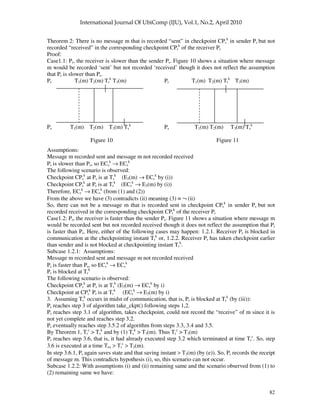
Case2.1: Figure 12 and Figure 13 show situations where message m would be recorded received
but not recorded sent. First we consider the case where Pr, the receiver is slower than the sender Ps.
Here, either of the following cases may happen: 2.1.1. Sender Ps is blocked in communication
during the checkpointing instant Ts
k
or, 2.1.2. Sender Ps has taken checkpoint earlier than receiver
and is not blocked during checkpointing instant Ts
k
.
For 2.1.1 let us consider figure 12 where the dashed line denotes a timing instant T where the
following situation is observed.
Pr T1(m) T2(m) T3(m) Tr
k
T Pr T1(m) T2(m) T3(m) Tr
k
T
Ps Ps
T1(m) T2(m) Ts
k
T3(m) Ts
k
T1(m) T2(m) T3(m)
Figure 12 Figure 13
Subcase 2.1.1. Assumptions:
Message m recorded received and message m not recorded sent
Ps is faster than Pr, so ECs
k
→ ECr
k
Ps is blocked at Ts
k
The following scenario is observed:
Checkpoint at Ps is at Ts
k
(ECs
k
→ E3(m) by (i))
Checkpoint at Pr is at Tr
k
(E3(m) → ECr
k
by (i))
Assuming Ps is blocked at Ts
k
(by (iii))
Ps reaches steps 3.1 and 3.2 of algorithm
In step 3.4 of algorithm Ps calls wait(event2) after Ts
k
.
Let Tr
c
= Instant of first occurrence of event1 in Pr after Tr
k
and
Ts
c
= Instant of first occurrence of event1 in Ps after Ts
k
By (ii) Ts
c
< Tr
c](https://image.slidesharecdn.com/0410iju5-250514150325-ebbca6e8/85/Checkpointing-with-Synchronized-Clocks-in-Distributed-Systems-20-320.jpg)
![84
By Theorem 1 Ts
c
> Tr
k
By (3d) and (3e) Tr
k
< Tr
c
Ps can not terminate wait(event2) before it receives sp_mess from Pr (by definition of event2)
Pr can send sp_mess to Ps only after Tr
c
(by Srikanth[15])
4. a) Pr is not blocked at Tr
k
(by assumption (i))
b) Pr takes checkpoint in step 2.1 of the algorithm at an instant ≥ Tr
k
(by 4(a) and
algorithm)
c) Pr calls wait(event1) in step 2.2. after Tr
k
(by 4(b) and sequential execution semantics)
d) Pr terminates wait(event1) after Tr
c
(by 3(f))
e) Pr executes step 2.3.1 (by 4(d)) to construct sp_mess after Tr
c
f) Tr
c
> T3(m) (by (2) and 3(f))
g) Pr records the receipt of message m in sp_mess (by 4(e) and 4(f))
5. Ps detects inconsistency in step 3.5.1 of algorithm
6. Ps modifies checkpoint CPs
k
in step 3.7 of the algorithm.
7. By (6) we have Ps recording the send of message m thereby contradicting assumption (i).
Hence the scenario 2.1.1 can not occur.
Subcase 2.1.2. Assumptions:
Message m not recorded sent by Ps but recorded received by Pr that is, Ts
k
< T3(m) and Tr
k
> T3(m)
Ts
k
< Tr
k
(since Ps is faster)
Ps is not blocked at Ts
k
that is, Ts
k
< T2(m)
The following scenario is observed:
Ps begins executing algorithm take_ckpt() at Ts
k
(by definition of Ts
k
)
2. Ps reaches step 2.2. of algorithm and commences wait(event1) at time Tx > Ts
k
(by (iii) Ps is not
blocked)
Ps can not participate in any event in the interval [Tx, Ts
c
]where Ts
c
is the time of occurrence of
event1 in Ps (by definition of wait(event1))
T2(m) denotes the time of an event in which Ps participates (by definition of T2(m) and since Ps
sends message m )
T2(m) ∉ [Tx, Ts
c
] (by (3) and (4))
(T2(m) < Tx) OR (T2(m) > Ts
c
) (by (5))
Ps is executing algorithm in the interval [Ts
k
, Tx] and hence can not participate in message transfer
in this interval (by (1) and (2))
T2(m) ∉ [Ts
k
, Tx] (by (4) and (7))
T2(m) > Ts
k
(by (8) and (iii))
From (6) using (9): (FALSE) OR (T2(m) > Ts
c
)
So, T2(m) > Ts
c
(by (10)
Therefore, EClks
c
→ E2(m) (by (11))
From Theorem 1 we have Ts
c
> Tr
k
, that is, ECr
k
→ EClks
c
Therefore, ECr
k
→ E2(m) (by (12) and (13))
Since E2(m) → E3(m) (section 2) and from (14) we have ECr
k
→ E3(m)
(15) therefore contradicts the scenario observed in (i) that is, E3(m) → ECr
k
or, Tr
k
> T3(m)
Thus it is proved that there can not be any message m that is recorded received but not recorded
sent under scenario 2.1.2.
Case2.2: Figure 14 shows a situation where message m would be recorded ‘received’ but not
recorded ‘sent’. Pr, the receiver is faster than the sender Ps. Let us consider figure14 (though it
does not reflect the fact that Pr is faster than Ps) where the dashed line denotes a timing instant T
where the following situation is observed.](https://image.slidesharecdn.com/0410iju5-250514150325-ebbca6e8/85/Checkpointing-with-Synchronized-Clocks-in-Distributed-Systems-21-320.jpg)
![85
Pr T1(m) T2(m) T3(m) Tr
k
T
Ps
Ts
k
T1(m) T2(m) T3(m)
Figure 14
Assumptions:
Message m recorded received and message m not recorded sent
Pr is faster than Ps, so ECr
k
→ ECs
k
The following scenario is observed:
Checkpoint at Ps is at Ts
k
(ECs
k
→ E3(m) by i)
Checkpoint at Pr is at Tr
k
(E3(m) → ECr
k
by i)
Therefore, ECs
k
→ ECr
k
(by 1 and 2)
4. (3) contradicts (ii)
So, there can not be any message m that is recorded received but not recorded sent under scenario
2.2.
Theorem 4: The checkpoints taken by the algorithm are consistent.
Proof: We would prove the theorem by contradiction. Let the checkpoints taken by the algorithm
be inconsistent. This means that either:
Case1: there is a missing message m, or
Case2: there is an orphan message m
Case1: It has been proved in Theorem 2 above that there can not be any missing message m
Case2: It has been proved in Theorem 3 above that there can not be any orphan message m
From Cases (1) and (2), which include all possible cases of inconsistencies, we see from above
that inconsistency can not occur in any of the cases.
This ends the proof of Theorem 4.
5.4. Approximate time of freezing after taking checkpoint
In a multiprogrammed environment CPU time-slice generally belongs to the range of 10 msec to
50 msec. Let us take the degree of multiprogramming to be 16 and average CPU time-slice to be
25 msec. So, average waiting time per process Wm approximately becomes : 375 msec (= (16 – 1)
* 25) msec). Typical round trip time (RTT) for a cross-country connection in USA is 100 msec
[11]. So, we choose tdel (Section 5.3) to be approximately equal to 50 msec in the following
calculations.
It is already stated in section 5.3 (in Proof of Theorem 1) that the checkpointing instant is chosen
to be: kP + α +0.5P (2)
and thus the immediate next clock synchronization instant would be
(k+1)P + α (3)
Hence maximum “freezing” time of a process is calculated to be 0.5P (by subtracting (2) from
(3)). From Srikanth [16] we have
P > tdel(1+ρ) + α (4)
We also have from Srikanth [16] the following relationship:
α ≥ [(1+ρ)Dmax + tdel](1+ρ) (5)
For small ρ: α ≥ Dmax+tdel (6)
Let ρ = 10-5
and tdel = 50 msec
We choose Dmax = 1.25*tdel (since Dmax ≥ tdel from (5a) in section 5.3)) = 62.5 msec
So, from (5) we have α ≥ 112.5 (= 50 + 62.5 )](https://image.slidesharecdn.com/0410iju5-250514150325-ebbca6e8/85/Checkpointing-with-Synchronized-Clocks-in-Distributed-Systems-22-320.jpg)
![87
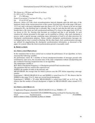
Performance Summary: (All time values are in seconds)
I BCF R cut_off_time
(with ckpt)
exec_time
(NO ckpt)
Chkpt
_
count
forced
ckpts
msgs_
passed
Overhead
(%)
0 0.001 0.00002180 8000.00 4031.12 1030 2 91763 98.46
1 0.002 0.00000000 8000.00 6014.73 515 0 136955 33.01
2 0.003 0.00000000 8000.00 6674,14 344 0 152405 19.87
3 0.004 0.00000000 8000.00 7005.94 258 0 160018 14.19
4 0.005 0.00000000 8000.00 7206.13 206 0 164339 11.02
5 0.006 0.00000000 8000.00 7337.13 172 0 167816 9.03
6 0.010 0.00000000 8000.00 7603.2 103 0 172768 5.22
7 0.022 0.00000000 8000.00 7818.70 47 0 179261 2.32
8 0.046 0.00000000 8000.00 7911.30 23 0 180243 1.12
II. Application Program parameters: MEAN-GRAIN=0.100000 sec, NODES = 20
Checkpoint parameters: TSAVESTATE=0.000000 Measuring overhead for freezing time only
Clock Synchronization parameters: P=8.000000,
RHO=0.000010,TDEL=0.065000,ALPHA=0.300000
Our general observation from the two different parameters is that the number of forced
checkpoints is extremely small, which automatically implies that our algorithm is extremely
efficient.
The overhead of freezing time (i.e., the time for which a process remains suspended after taking a
checkpoint) is higher at low values of BCF, i.e, at high checkpointing frequencies. For a BCF of
0.010, the overhead can be as low as 5.23%. Thus, if the execution time with instantaneous
checkpoints is 8000 sec during which 103 checkpoints are taken, the execution time with no
checkpointing would be 7602.74 sec. With NODES = 6 and MEAN-GRAIN = 0.16 sec, there
would be 55552 messages exchanged among the nodes.
The highest value of R = 0.00006022 that we have obtained is orders of magnitude lower than R =
0.35 of [22].](https://image.slidesharecdn.com/0410iju5-250514150325-ebbca6e8/85/Checkpointing-with-Synchronized-Clocks-in-Distributed-Systems-24-320.jpg)
![88
Performance Summary: (All time values are in seconds)
I BCF R cut_off_time
(with ckpt)
exec_time
(NO ckpt)
chkpt_
count
forced
ckpts
msgs_
passed
Overhead
(%)
0 0.001 0.00000000 8000.00 4027.24 1030 0 115250 98.65
1 0.002 0.00000000 8000.00 6013.36 515 0 172335 33.04
2 0.003 0.00000000 8000.00 6673.08 344 0 190203 19.88
3 0.004 0.00000000 8000.00 7004.65 258 0 200944 14.21
4 0.005 0.00000000 8000.00 7205.52 206 0 205632 11.03
5 0.006 0.00000000 8000.00 7336.92 172 0 210144 9.04
6 0.010 0.00000000 8000.00 7602.50 103 0 218196 5.23
7 0.022 0.00000892 8000.00 7818.73 47 2 224092 2.32
8 0.046 0.00000000 8000.00 7911.02 23 0 226798 1.12
7. CONCLUSION
We have presented here a synchronized-clock-based checkpointing method. This method does not
have a central checkpoint coordinator that poses a single point failure threat to the system. The
overhead of coordinating messages is also absent since clock synchronization messages have been
utilized for checkpoint-synchronizing purposes. Though frequency of checkpointing is basically
driven by the requirement of the application program the time for which processes have to wait to
synchronize their checkpointing action is not an overhead since the clock synchronization
frequency can be adjusted to meet the requirement. At the same time it must be ensured that clock
synchronization itself does not become an overhead. So, coordinating messages for synchronizing
the checkpointing action may be used in cases where the clocks are well synchronized. Since any
global checkpoint is consistent, only one checkpoint needs to be stored in the stable storage [7].
The old checkpoint in a process is deleted once checkpointing synchronization is over and the new
checkpoint is written. So, the system does not have to roll back more than once to restart from a
previous consistent state in case recovery is required.
REFERENCES
1. K.M.Chandy, & L.Lamport, (1985) Distributed Snapshots: Determining Global States of Distributed
Systems, ACM Trans. On Computer Systems, Vol. 3, No.1, pp. 63-75.
2. S.Kalaiselvi & V.Rajaraman, (1997) Checkpointing Algorithm for Parallel Computers based on
Bounded Clock Drifts; Computer Science & Informatics, Vol. 27, No. 3, pp. 7-11
3. R.Koo & S.Toueg, (1987) Checkpointing and Rollback Recovery for Distributed Systems, IEEE Trans.
on Software Engineering, Vol. SE-13, No.1, pp. 28-31.
4. L. Lamport, (1978) Time, Clocks and the Ordering of Events in a Distributed System, Communications
of the ACM, Vol. 21, No. 7, pp. 558-565.](https://image.slidesharecdn.com/0410iju5-250514150325-ebbca6e8/85/Checkpointing-with-Synchronized-Clocks-in-Distributed-Systems-25-320.jpg)


![[Deck] What's New in Spark-Iceberg Integration via DSV2.pptx](https://cdn.slidesharecdn.com/ss_thumbnails/deckwhatsnewinspark-icebergintegrationviadsv2-260210005337-25955b12-thumbnail.jpg?width=640&height=640&fit=bounds)


