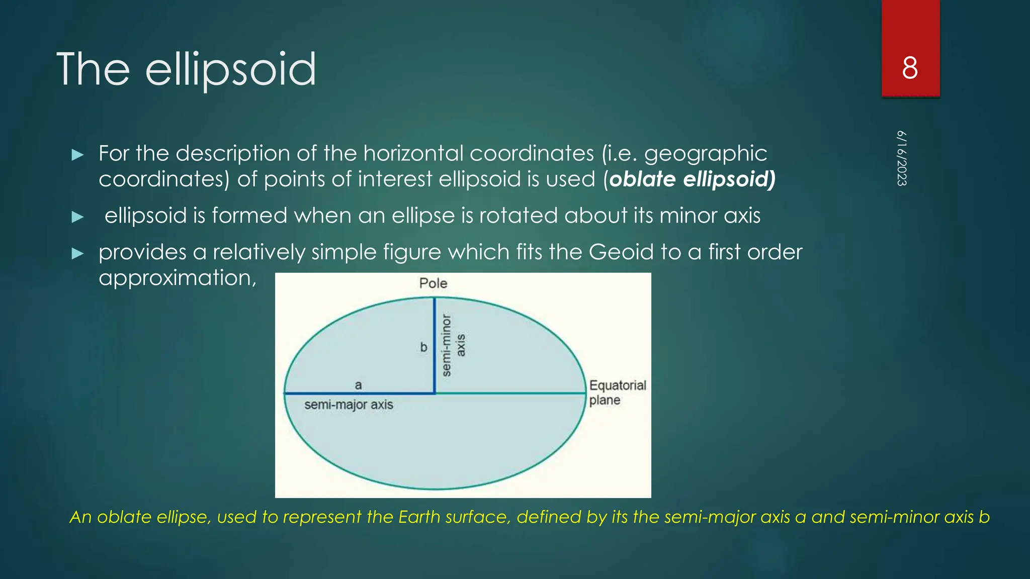
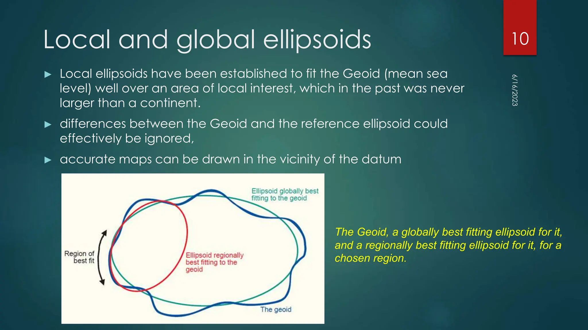
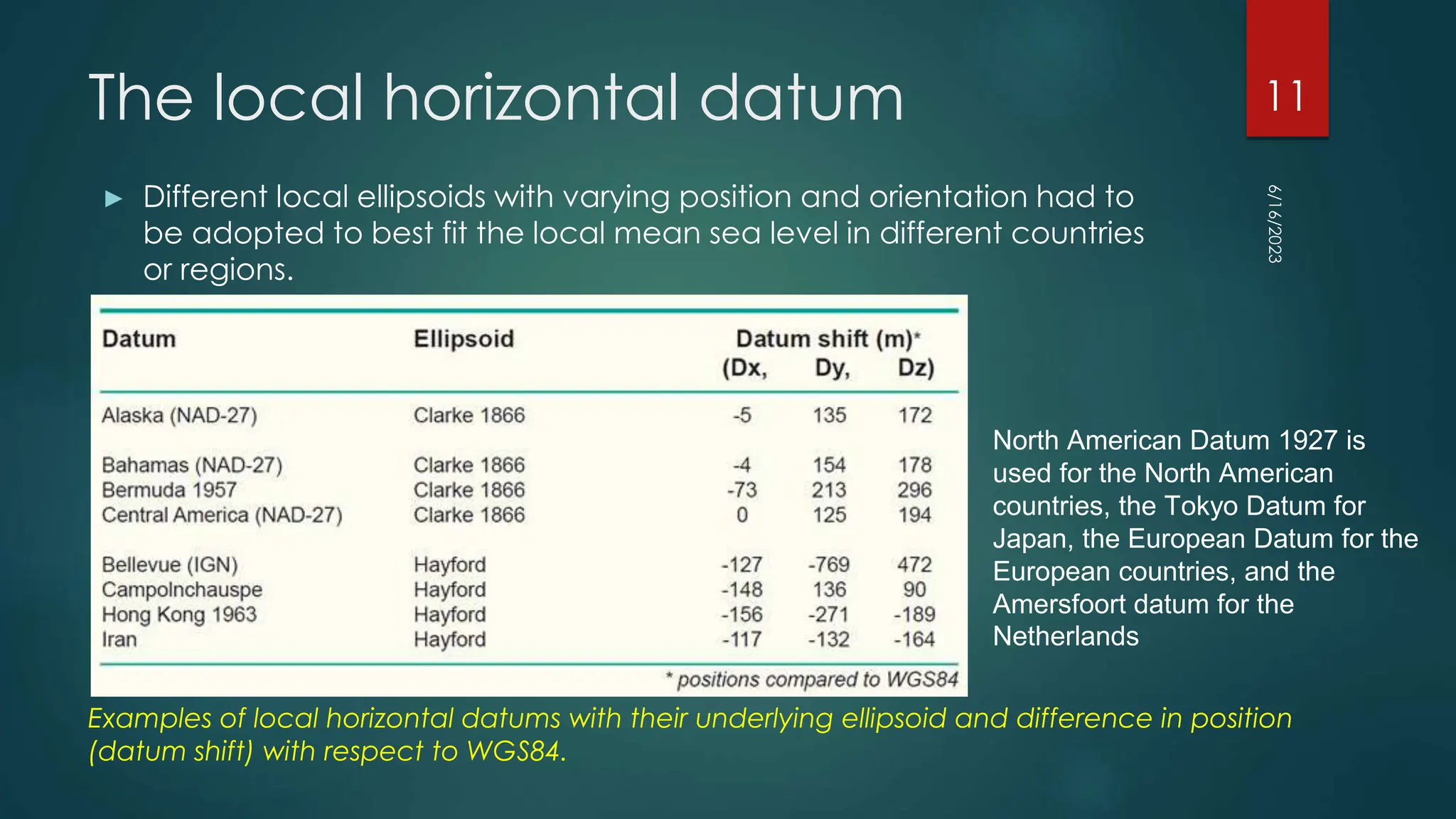
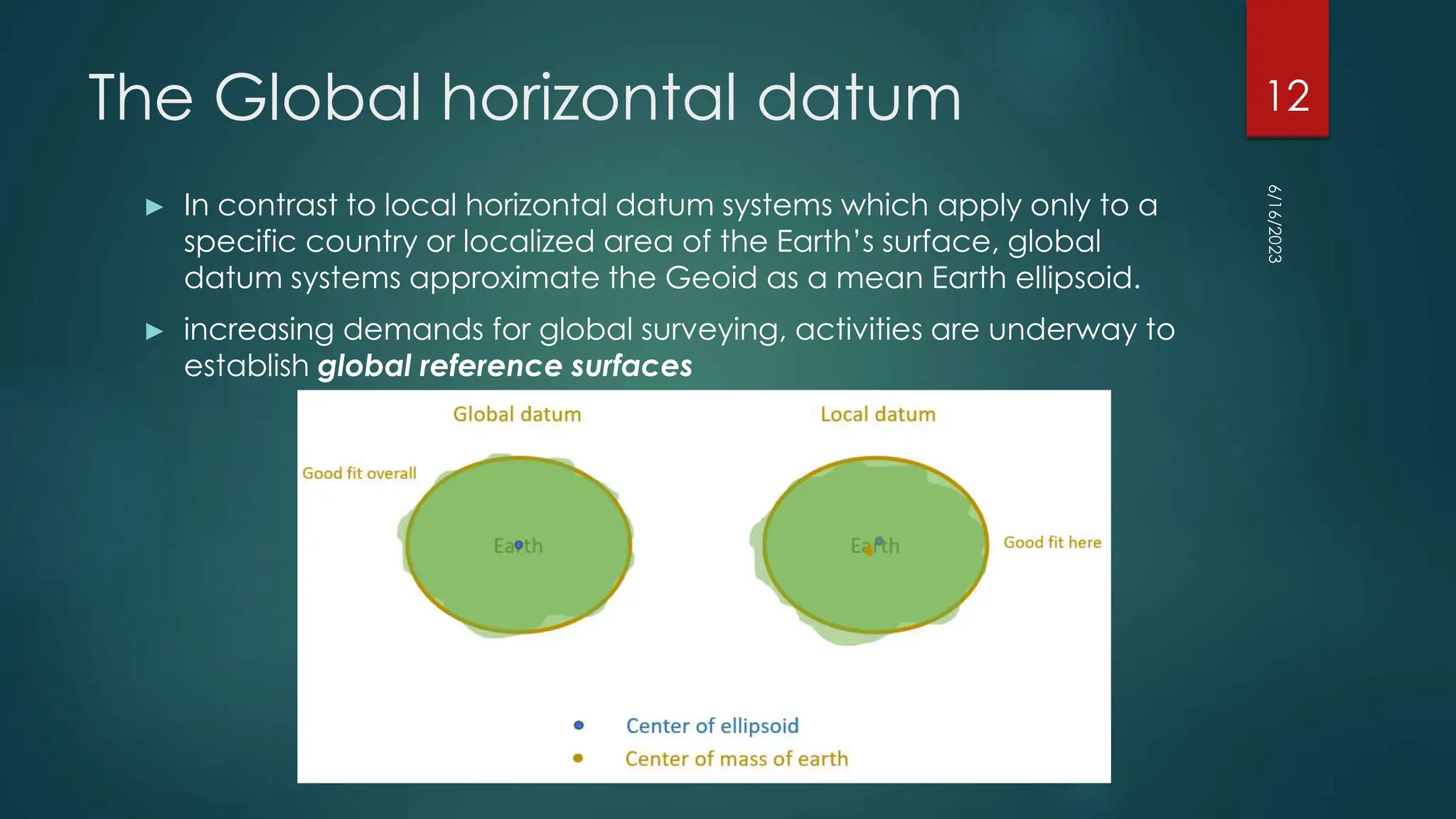
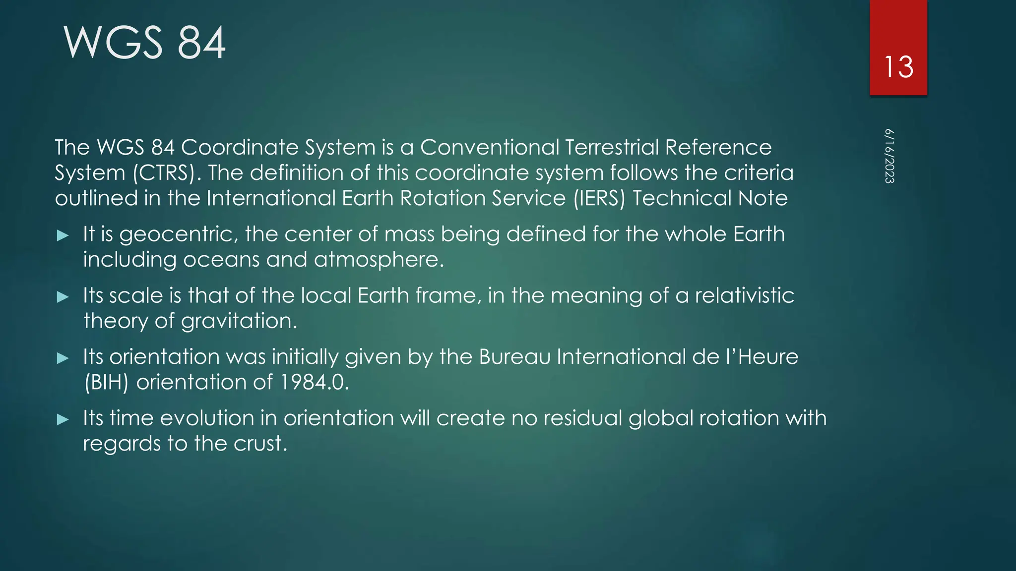
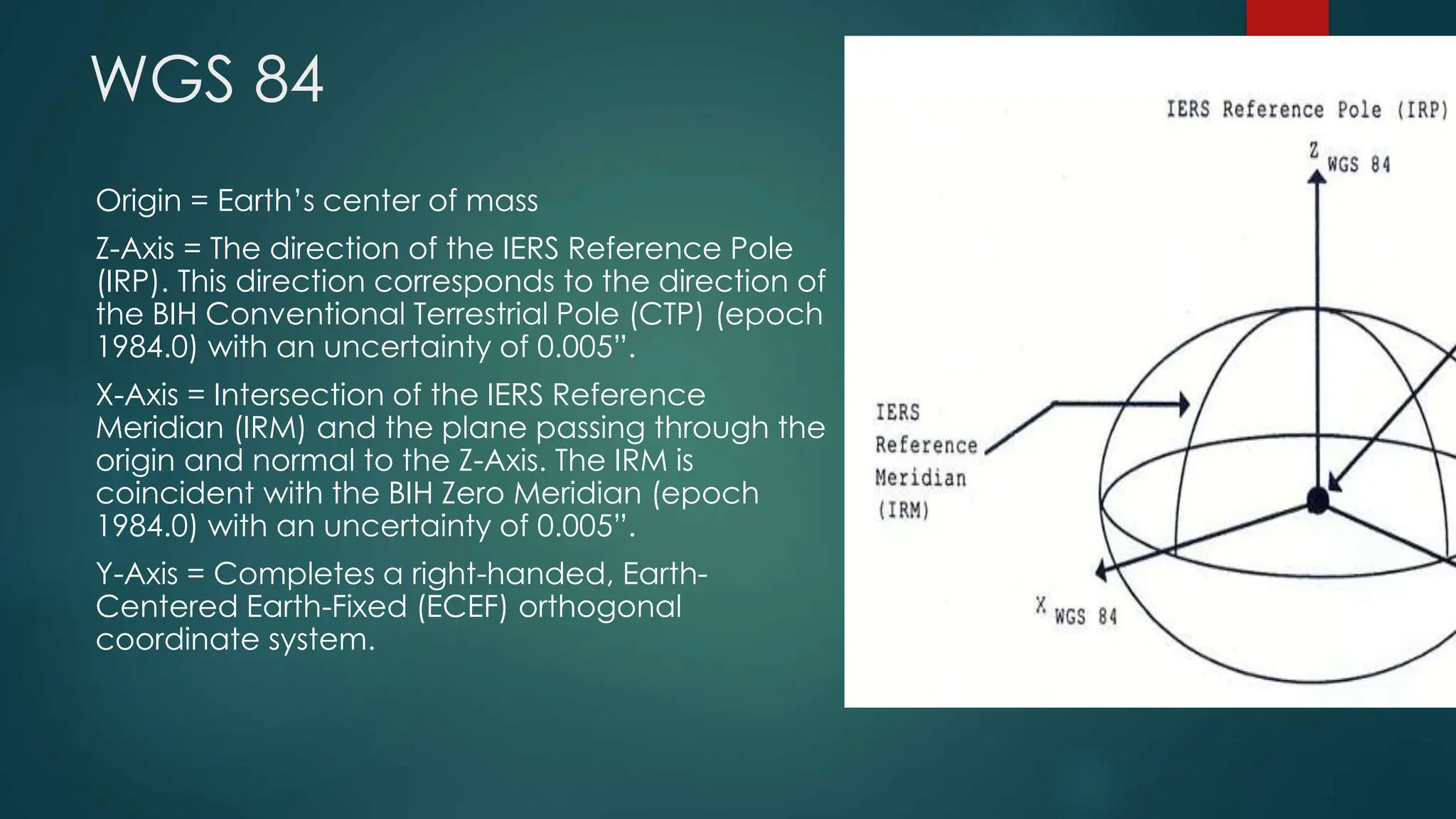
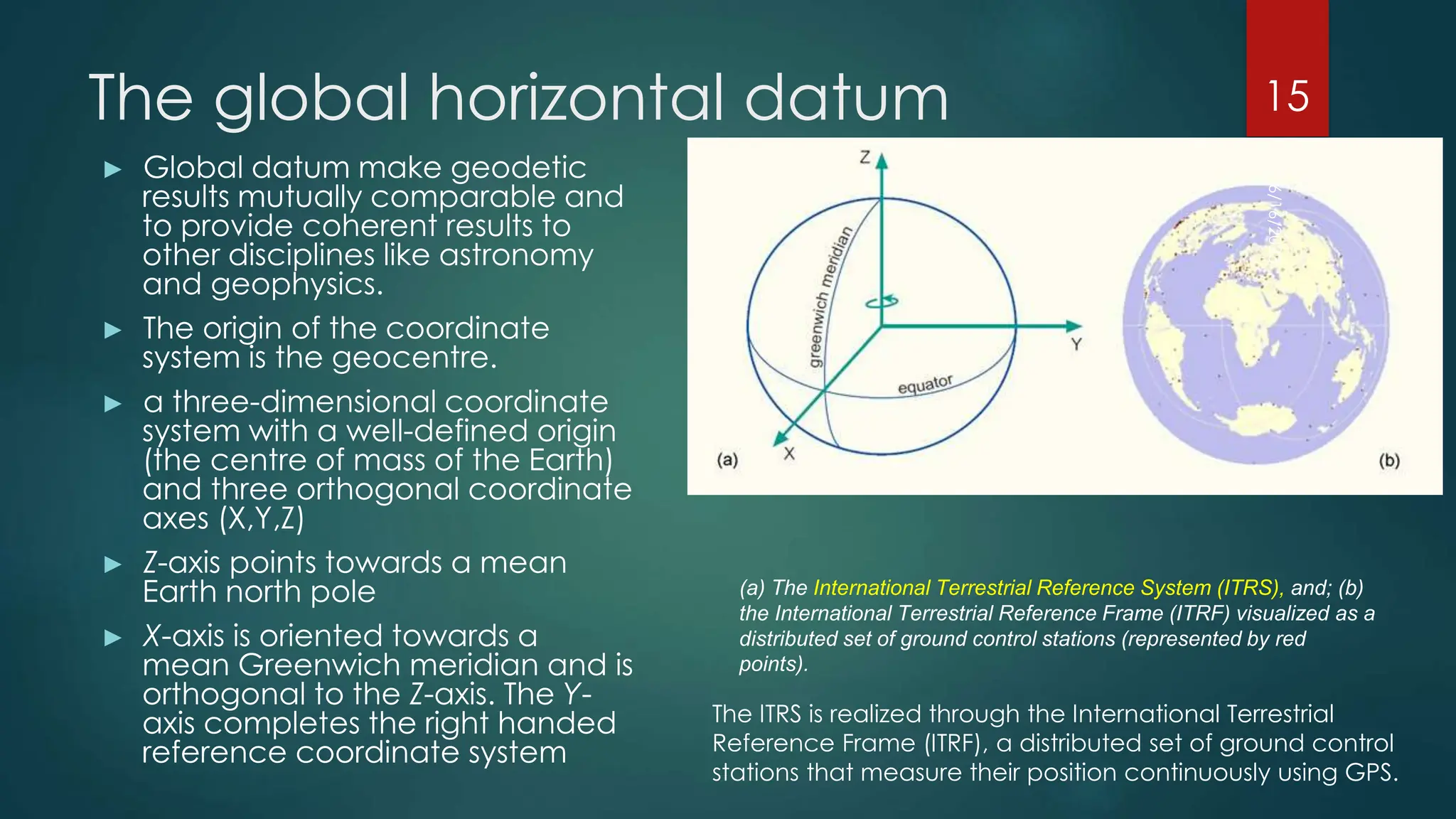
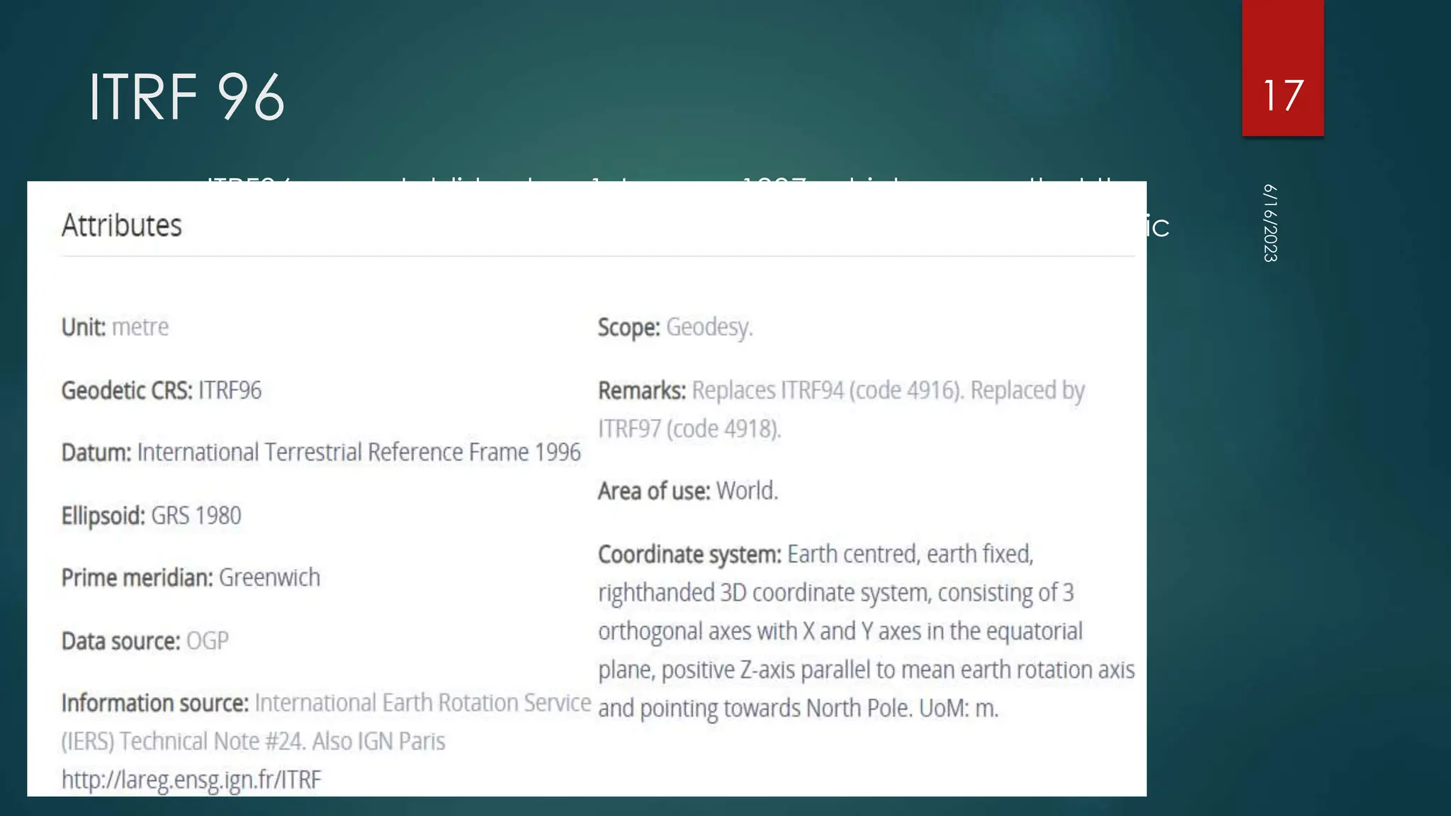
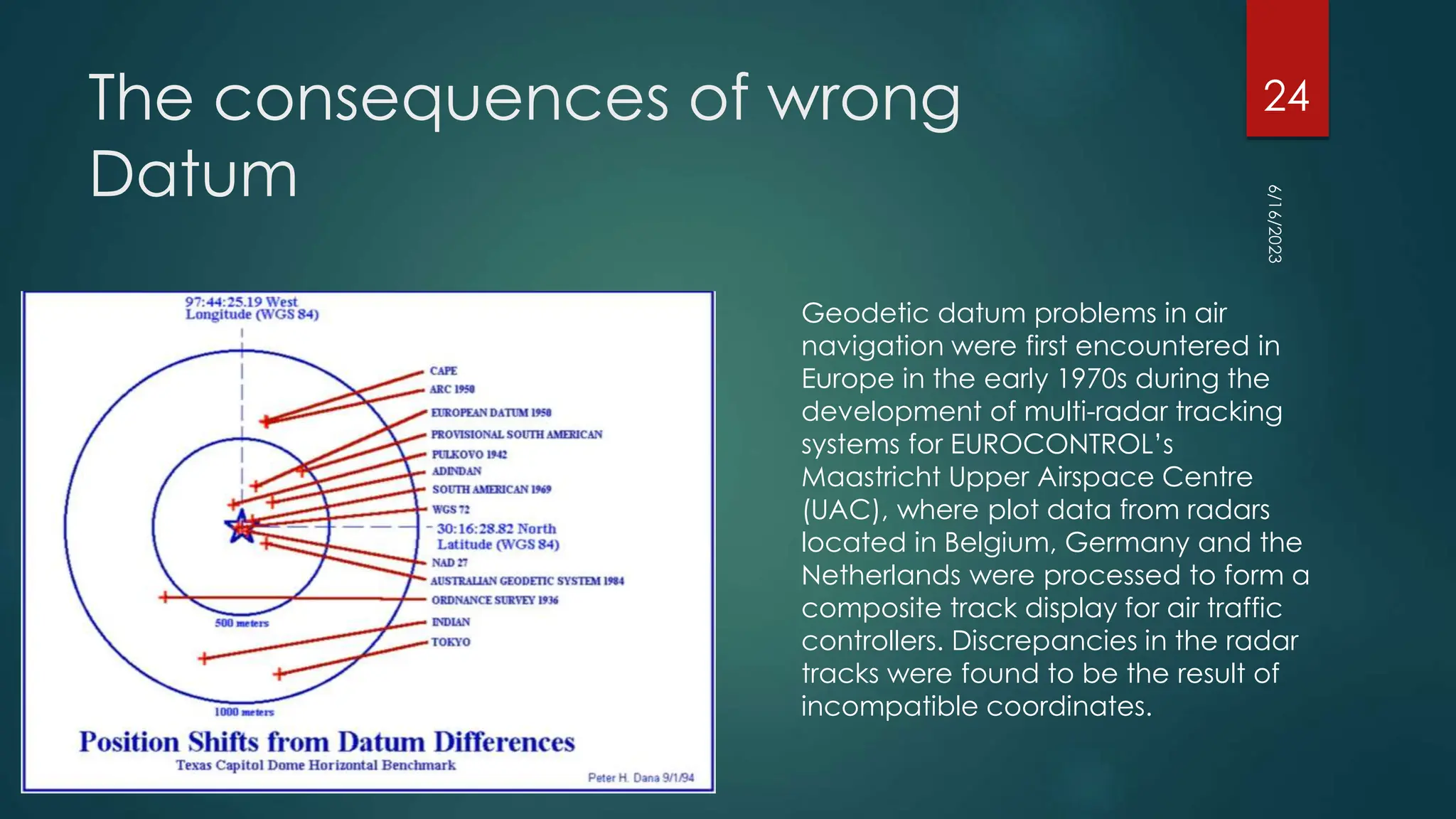
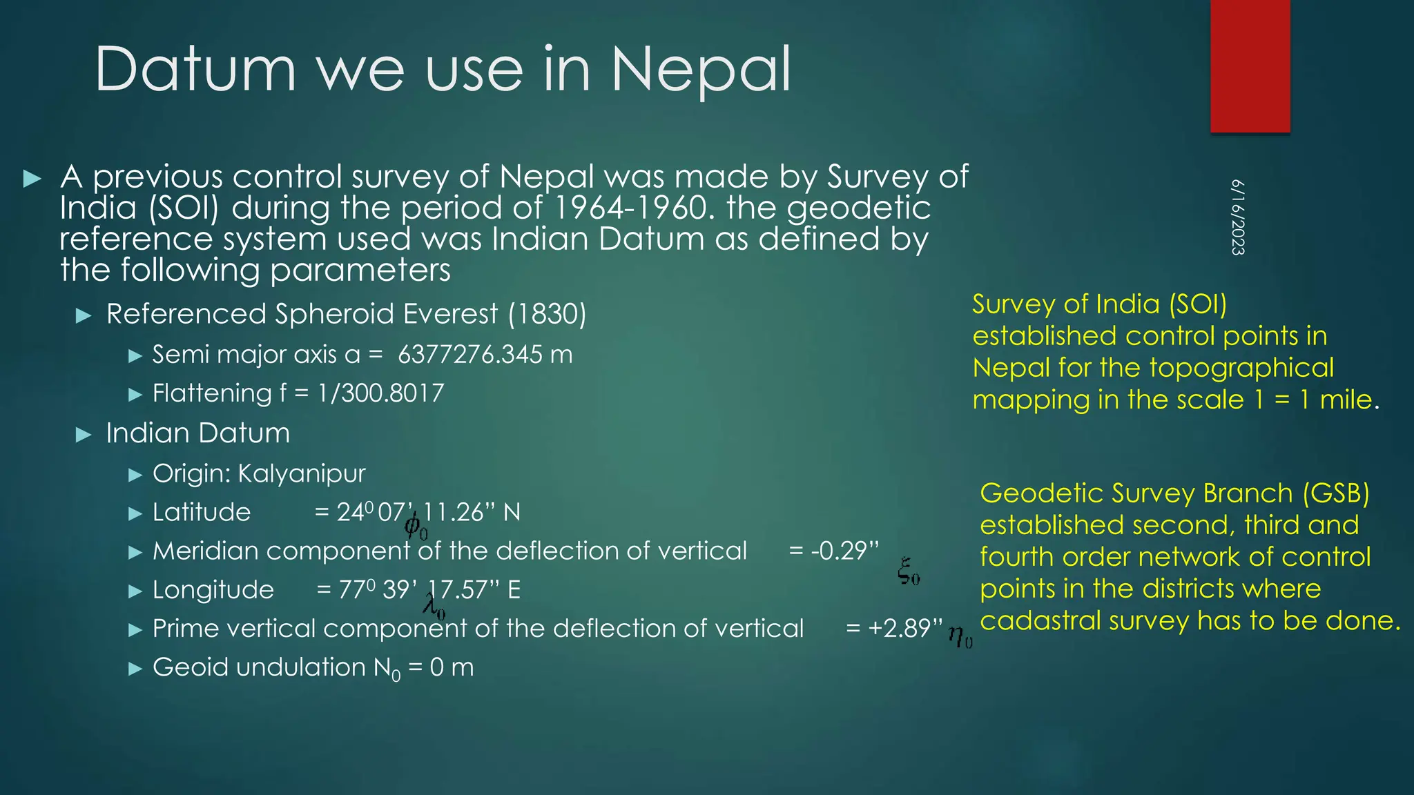
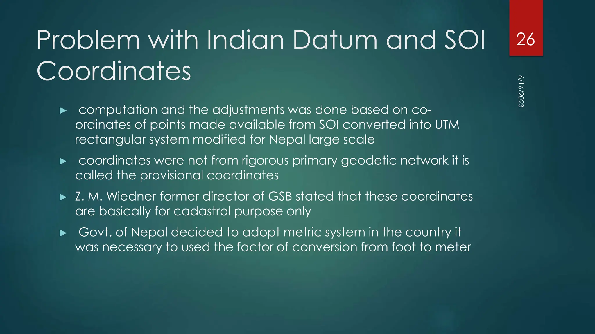
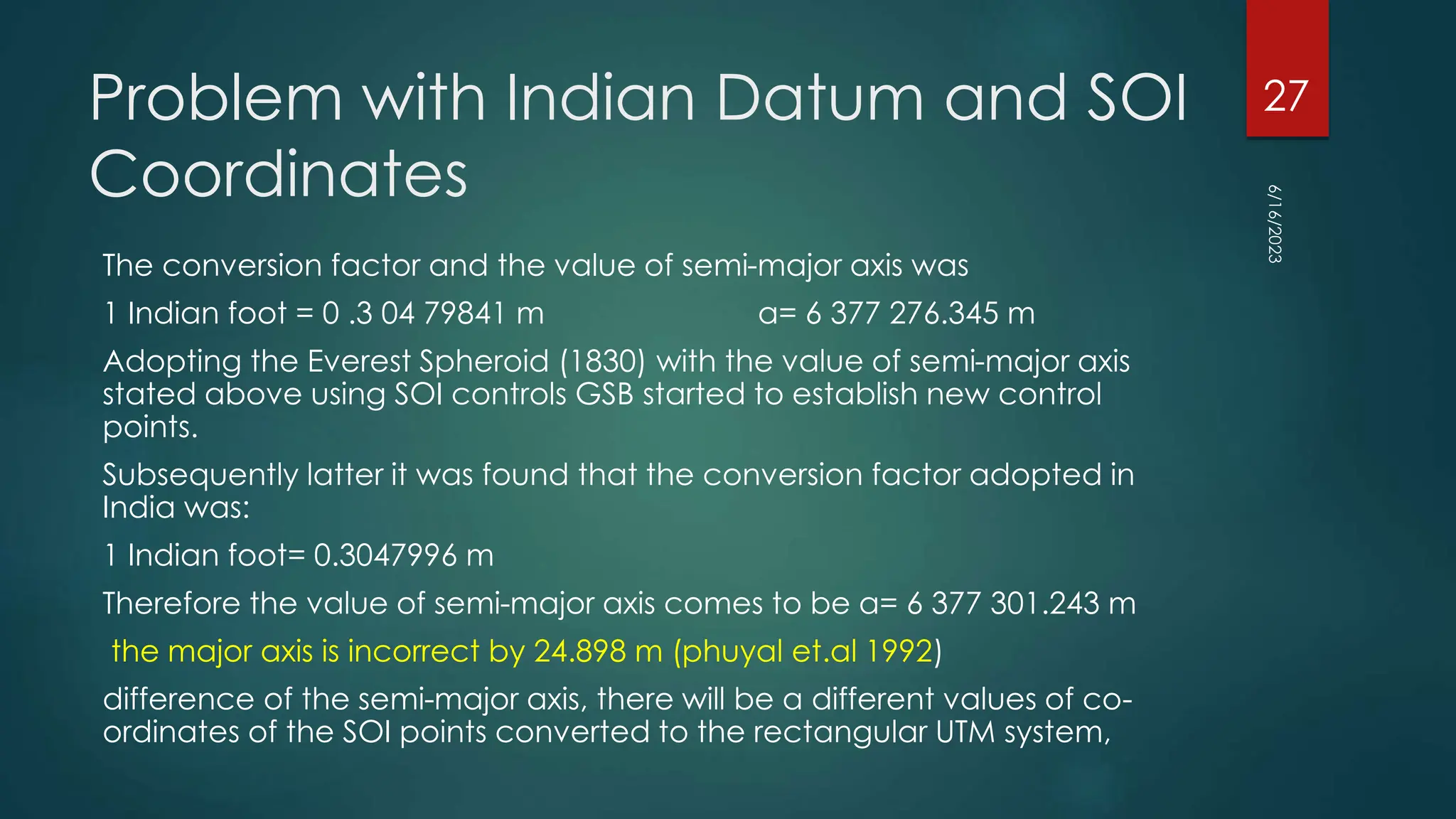
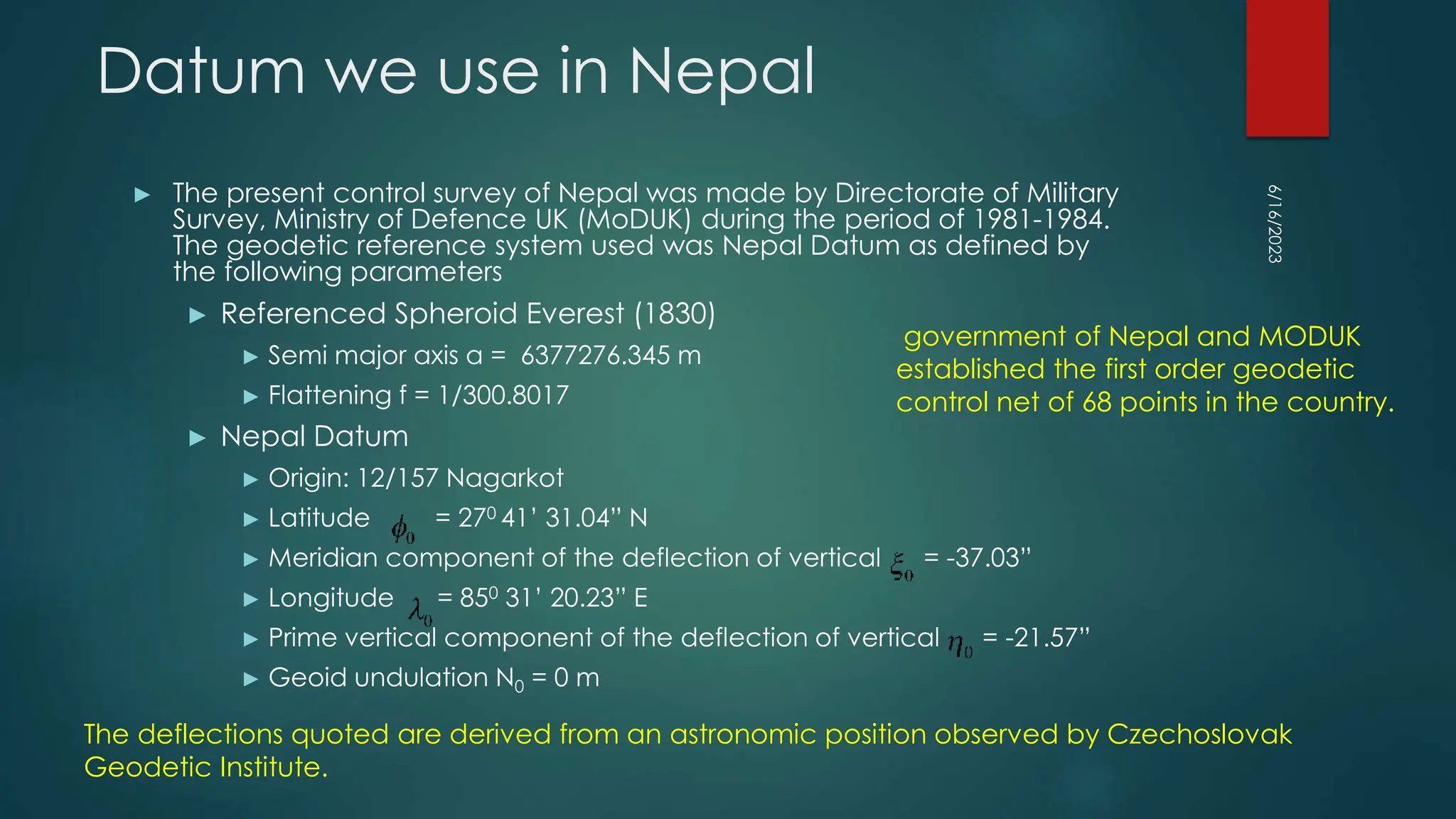
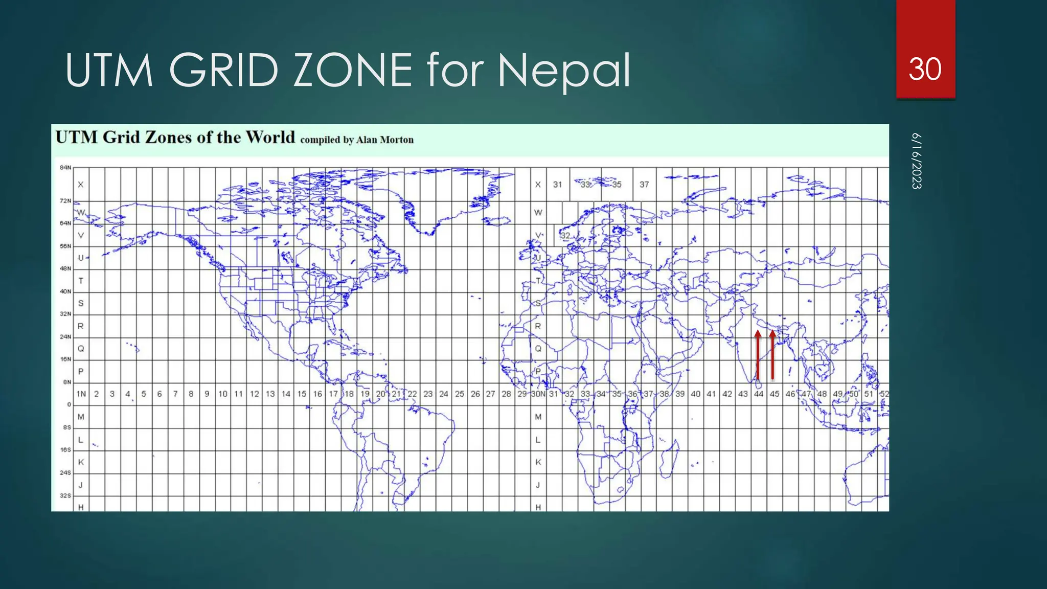
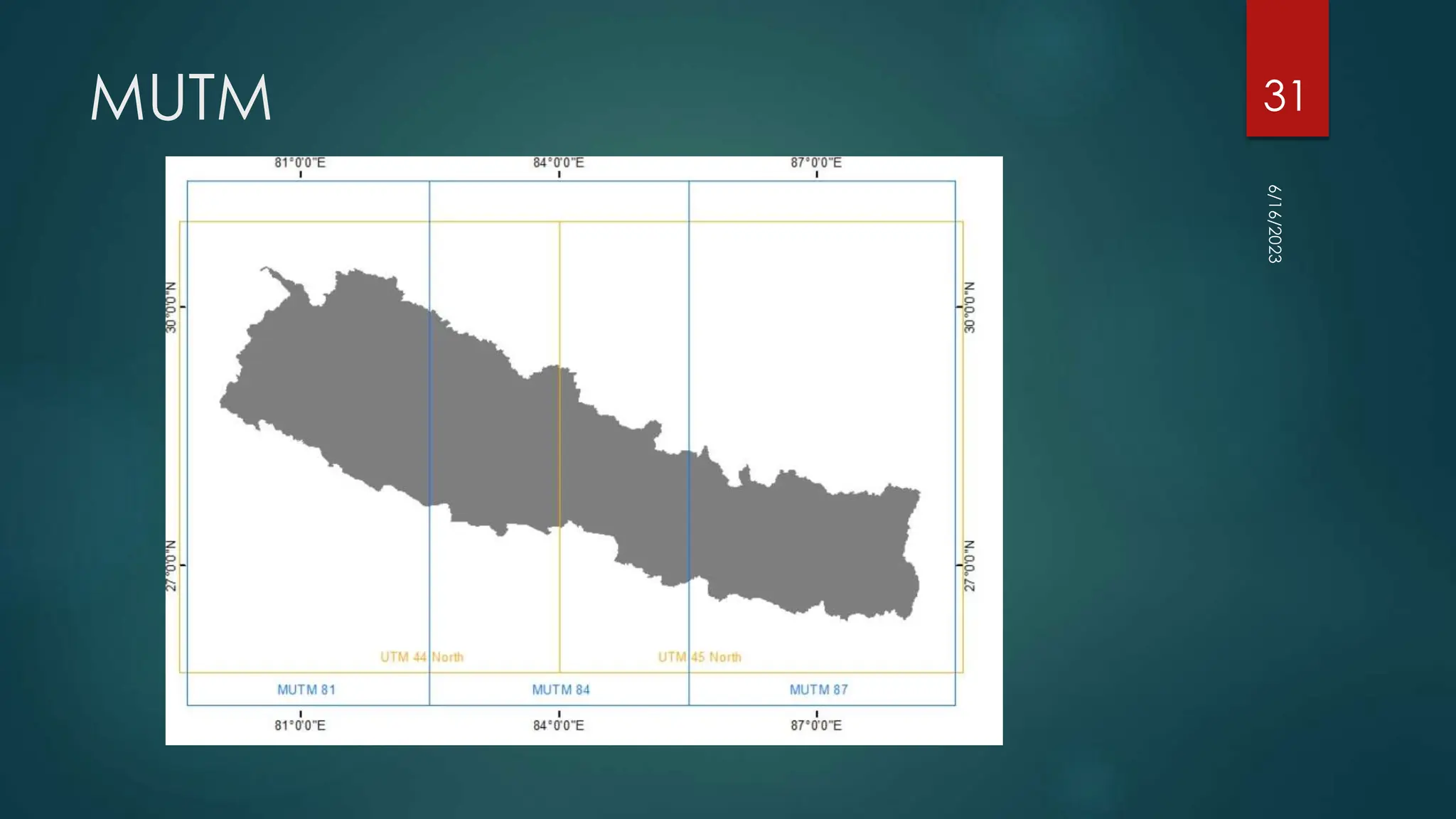
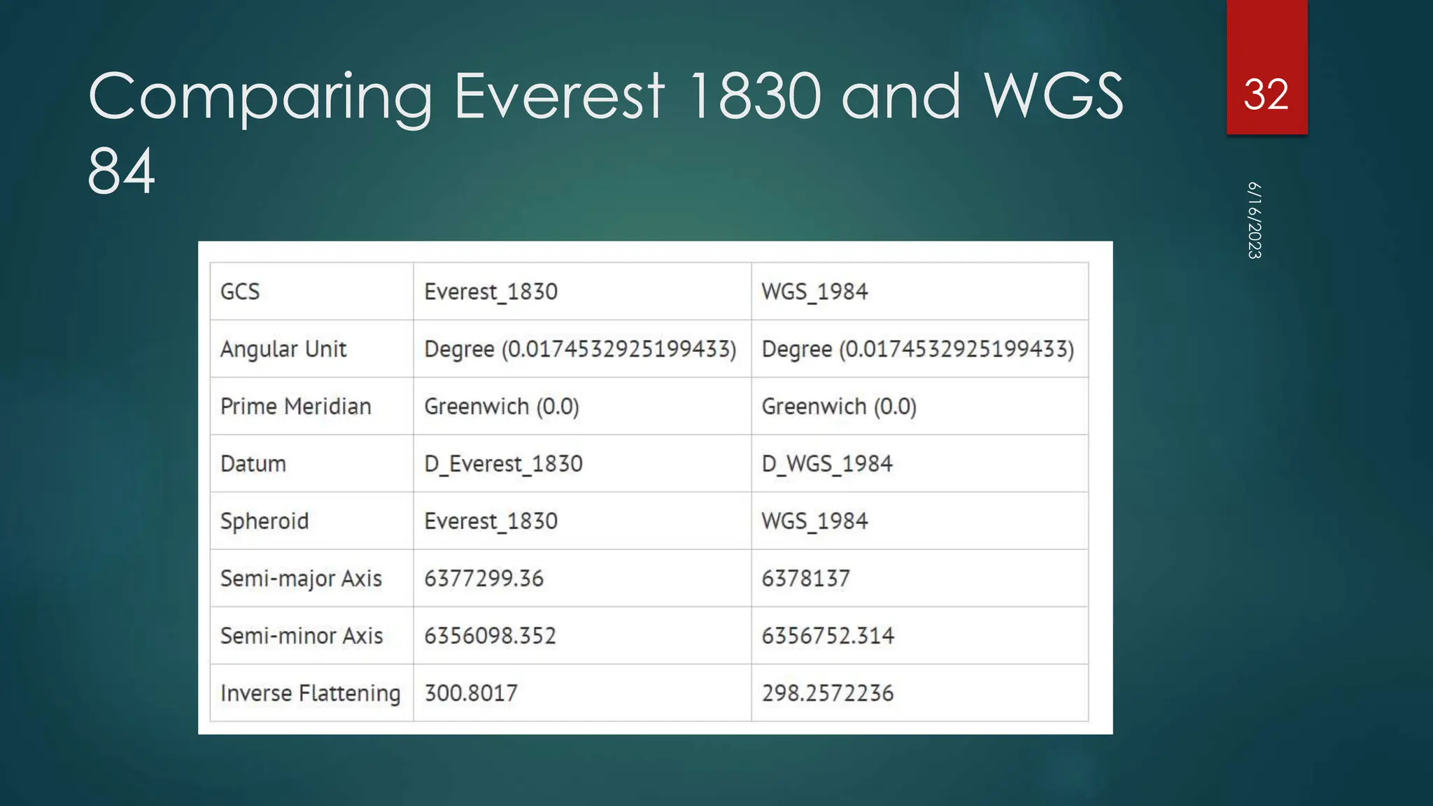
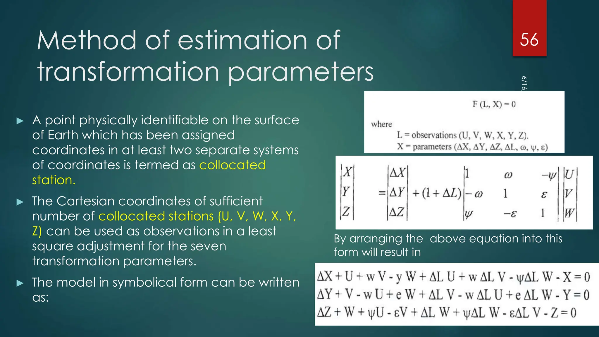
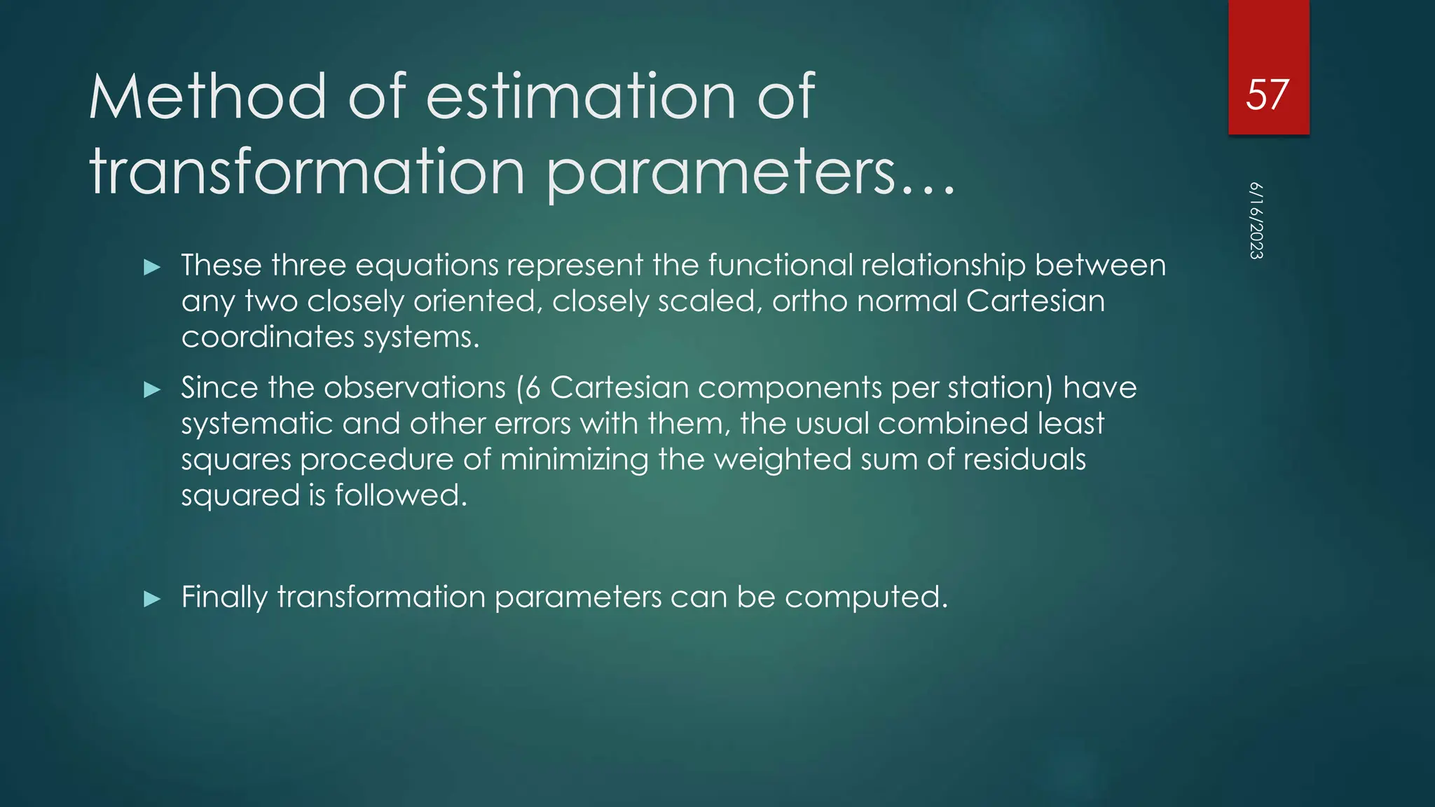
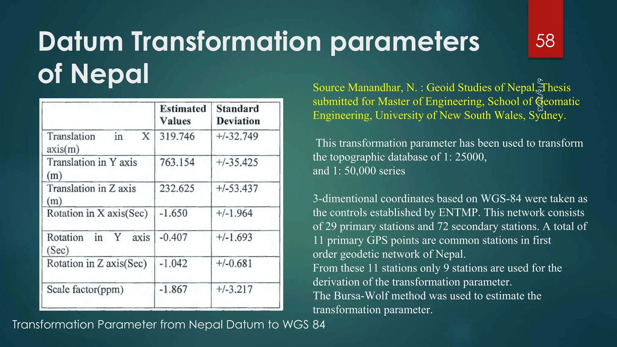
Chapter 2:
Reference System
GE 601
UMESH BHURTYAL
PASHCHIMANCHAL CAMPUS
6/16/2023
1
Content
► Reference system: 7 Hrs
► 2.1 Plane coordinate system, geodetic coordinate system,
Geodetic, geocentric and astronomical latitude, Geodetic, geocentric
and astronomical longitude, Earth centered Earth fixed coordinate
system, Laplace equation, deflection of vertical and Laplace station.
► 2.2 International terrestrial reference system (ITRF), WGS72, NAD83,
WGS84 and Everest 1830 Ellipsoidal datum, Datum transformation from
geodetic system to Cartesain and vice versa, determination of
transformation parameters.
6/16/2023
2
Spatial Reference
► Spatial Reference = Datum + Projection + Coordinate system
► Datum – Horizontal and Vertical Datum
► Projection
► Coordinate System
► Coordinate systems are the central - mathematical - element of any
geodetic reference system.
map projection is one of many
methods used to represent the
3-dimensional surface of the
earth or other round body on a
2-dimensional plane in
cartography (mapmaking)
6/16/2023
3
Spatial Reference System
Creating an unambiguous way of referencing location on the surface
of the earth.
6/16/2023
4
Important of reference frame
► national and regional surveying and mapping works are all based
on one single framework of geodetic control which is considered as
a primary network of the country
► Applied in:
► Defense
► satellite lunching,
► missiles projecting ,
► construction of major infrastructures of the country (dams, roads,
sewerage system, irrigation, hydropower stations etc).
6/16/2023
5
Reference Surfaces
► A reference surface is a datum that provide a reference point to the
Earth's surface
► Two main reference surfaces (or Earth figures) are used to approximate
the shape of the Earth
► Geoid
► Ellipsoid
► the Geoid is the equipotential surface at mean sea level and is used for
measuring heights represented on maps.
► starting point for measuring these heights are mean sea level points
established at coastal places
► ellipsoid (also called spheroid) provides a relatively simple
mathematical figure of the Earth
► used to measure locations, the latitude (φ) and longitude (λ)of points of
interest
► Some well known ellipsoids are the WGS84, GRS80, International 1924
(also known as Hayford), Krasovsky, Bessel, or the Clarke 1880 ellipsoid.
6/16/2023
6
Geoid
The geoid is the shape that the ocean surface would have under the sole influence of gravity and
the Earth’s rotation.
when we say that the top of a hill is 130 metres above sea level, we actually consider it to
be 130 metres above the geoid
plumb line through any surface point is always perpendicular to Geoid
6/16/2023
7
The ellipsoid
► For the description of the horizontal coordinates (i.e. geographic
coordinates) of points of interest ellipsoid is used (oblate ellipsoid)
► ellipsoid is formed when an ellipse is rotated about its minor axis
► provides a relatively simple figure which fits the Geoid to a first order
approximation,
An oblate ellipse, used to represent the Earth surface, defined by its the semi-major axis a and semi-minor axis b
6/16/2023
8
Defining Ellipsoid
► Flattening f
Flattening f is dependent on both the semi-major axis a and the
semi-minor axis b.
► The ellipsoid may also be defined by its semi-major axis a and
eccentricity e, which is given by:
6/16/2023
9
Local and global ellipsoids
► Local ellipsoids have been established to fit the Geoid (mean sea
level) well over an area of local interest, which in the past was never
larger than a continent.
► differences between the Geoid and the reference ellipsoid could
effectively be ignored,
► accurate maps can be drawn in the vicinity of the datum
The Geoid, a globally best fitting ellipsoid for it,
and a regionally best fitting ellipsoid for it, for a
chosen region.
6/16/2023
10
The local horizontal datum
► Different local ellipsoids with varying position and orientation had to
be adopted to best fit the local mean sea level in different countries
or regions.
Examples of local horizontal datums with their underlying ellipsoid and difference in position
(datum shift) with respect to WGS84.
North American Datum 1927 is
used for the North American
countries, the Tokyo Datum for
Japan, the European Datum for the
European countries, and the
Amersfoort datum for the
Netherlands
6/16/2023
11
The Global horizontal datum
► In contrast to local horizontal datum systems which apply only to a
specific country or localized area of the Earth’s surface, global
datum systems approximate the Geoid as a mean Earth ellipsoid.
► increasing demands for global surveying, activities are underway to
establish global reference surfaces
6/16/2023
12
WGS 84
The WGS 84 Coordinate System is a Conventional Terrestrial Reference
System (CTRS). The definition of this coordinate system follows the criteria
outlined in the International Earth Rotation Service (IERS) Technical Note
► It is geocentric, the center of mass being defined for the whole Earth
including oceans and atmosphere.
► Its scale is that of the local Earth frame, in the meaning of a relativistic
theory of gravitation.
► Its orientation was initially given by the Bureau International de l’Heure
(BIH) orientation of 1984.0.
► Its time evolution in orientation will create no residual global rotation with
regards to the crust.
6/16/2023
13
WGS 84
Origin = Earth’s center of mass
Z-Axis = The direction of the IERS Reference Pole
(IRP). This direction corresponds to the direction of
the BIH Conventional Terrestrial Pole (CTP) (epoch
1984.0) with an uncertainty of 0.005”.
X-Axis = Intersection of the IERS Reference
Meridian (IRM) and the plane passing through the
origin and normal to the Z-Axis. The IRM is
coincident with the BIH Zero Meridian (epoch
1984.0) with an uncertainty of 0.005”.
Y-Axis = Completes a right-handed, Earth-
Centered Earth-Fixed (ECEF) orthogonal
coordinate system.
6/16/2023
14
The global horizontal datum
► Global datum make geodetic
results mutually comparable and
to provide coherent results to
other disciplines like astronomy
and geophysics.
► The origin of the coordinate
system is the geocentre.
► a three-dimensional coordinate
system with a well-defined origin
(the centre of mass of the Earth)
and three orthogonal coordinate
axes (X,Y,Z)
► Z-axis points towards a mean
Earth north pole
► X-axis is oriented towards a
mean Greenwich meridian and is
orthogonal to the Z-axis. The Y-
axis completes the right handed
reference coordinate system
(a) The International Terrestrial Reference System (ITRS), and; (b)
the International Terrestrial Reference Frame (ITRF) visualized as a
distributed set of ground control stations (represented by red
points).
The ITRS is realized through the International Terrestrial
Reference Frame (ITRF), a distributed set of ground control
stations that measure their position continuously using GPS.
6/16/2023
15
International Terrestrial Reference
System (ITRS)
► This is a three-dimensional coordinate system with a well-
defined origin (the centre of mass of the Earth) and three
orthogonal coordinate axes (X, Y, Z).
► The Z-axis points towards a mean North Pole. The X-axis is
oriented towards the mean Greenwich meridian and is
orthogonal to the Z-axis. The Y -axis completes the right-handed
reference coordinate system.
► Constant re-measuring is needed (addition of new control
stations and ongoing geophysical processes (mainly tectonic
plate motion))
► deformations cause positional differences over time and have
resulted in more than one realization of the ITRS
► Examples are the ITRF96 and the ITRF2000.
► ITRF2000 or WGS84, are also called geocentric datums
6/16/2023
16
ITRF 96
► ITRF96 was established on 1 January 1997, which means that the
measurements use data acquired up to 1996 to fix the geocentric
coordinates (X, Y and Z in metres) and velocities (positional
change in X, Y and Z in metres per year) of the different stations
6/16/2023
17
ITRF 2000
► an improved frame in terms of quality, network and datum
definition
► The ITRF2000 solution reflects the actual quality of space geodesy
solutions, being free from any external constraints.
► It includes primary core stations observed by VLBI, LLR, SLR, GPS, and
DORIS (usually used in previous ITRF versions) as well as regional GPS
networks for its densification.
6/16/2023
18
ITRF 2020
► ITRF2020 is the new realization of the International Terrestrial
Reference System. Following the procedure already used for
previous ITRF solutions, the ITRF2020 uses as input data time series of
station positions and Earth Orientation Parameters (EOPs) provided
by the Technique Centers of the four space geodetic techniques
(VLBI, SLR, GNSS and DORIS), as well as local ties at colocation sites.
Based on completely reprocessed solutions of the four techniques,
the ITRF2020 is expected to be an improved solution compared to
ITF2014
6/16/2023
19
ITRF 2020
► A number of innovations were introduced in the ITRF2020
processing, including:
▪ The time series of the four techniques were stacked all together,
adding local ties and equating station velocities and seasonal
signals at colocation sites;
▪ Annual and semi-annual terms were estimated for stations of the 4
techniques with sufficient time spans;
▪ Post-Seismic Deformation (PSD) models for stations subject to major
earthquakes were determined by fitting GNSS/IGS data. The PSD
models were then applied to the 3 other technique time series at
earthquake colocation sites.
6/16/2023
20
Difference between ITRS and ITRF
► ITRF (International Terrestrial Reference Frame): The ITRF is a three-
dimensional coordinate reference frame that provides a precise and
consistent set of coordinates for points on the Earth's surface and in space.
It is used as a common reference system by scientists, engineers, and
surveyors worldwide. The ITRF is updated periodically to incorporate new
measurements and improved modeling techniques.
► ITRS (International Terrestrial Reference System): The ITRS is a geocentric
reference system that serves as the mathematical foundation for the ITRF. It
defines the Earth's rotation and orientation parameters and provides a
framework for relating the Earth-centered coordinates of the ITRF to the
Earth's physical motion in space. The ITRS takes into account the motion of
the Earth's tectonic plates, the effects of continental drift, and other
geodynamic processes
ITRS provides the theoretical framework for describing the Earth's rotation and
orientation, while the ITRF is the practical realization of that framework,
providing the actual coordinates for points on the Earth's surface and in
space.
6/16/2023
21
Space techniques contributing to
ITRS
• very long baseline interferometry (VLBI)
(high precision and long term stability)
• satellite laser ranging (SLR)
(long term stability and geo-centricity)
• lunar laser ranging (LLR)
(geo-centricity, long term stability,
relativistic effects)
• the French tracking system DORIS
(excellent global station distribution)
• Global Positioning System
(densest global network, short term
stability, high precision).
Since the tracking network equipped with
the instruments of these techniques is
evolving and the period of data available
increases with time, the ITRF is constantly
being updated.
6/16/2023
22
► VLBI
► VLBI provides the orientation of the ITRF relative to the celestial reference
frame (i.e., the ‘distant stars’) and is also one of the two techniques
currently used for accurately realizing the scale of the ITRF.
► SLR
► SLR is used to locate the center of mass of the Earth system and thereby
defines the ITRF origin and contributes to the ITRF scale.
► GPS
► GPS contributes the large number of sites that define the ITRF (contributing
to its density) and contributes to precise monitoring of polar motion.
► GPS, DORIS, and SLR are used to position space-orbiting platforms in the
ITRF, and GPS is used to position instruments on the Earth’s land and sea
surfaces (for example, tide gauges and buoys).
None of the space geodesy techniques alone is
capable of providing all the necessary parameters
for ITRF definition (origin, scale, and orientation).
6/16/2023
23
The consequences of wrong
Datum
6/16/2023
24
Geodetic datum problems in air
navigation were first encountered in
Europe in the early 1970s during the
development of multi-radar tracking
systems for EUROCONTROL’s
Maastricht Upper Airspace Centre
(UAC), where plot data from radars
located in Belgium, Germany and the
Netherlands were processed to form a
composite track display for air traffic
controllers. Discrepancies in the radar
tracks were found to be the result of
incompatible coordinates.
Datum we use in Nepal
► A previous control survey of Nepal was made by Survey of
India (SOI) during the period of 1964-1960. the geodetic
reference system used was Indian Datum as defined by
the following parameters
► Referenced Spheroid Everest (1830)
► Semi major axis a = 6377276.345 m
► Flattening f = 1/300.8017
► Indian Datum
► Origin: Kalyanipur
► Latitude = 240 07’ 11.26” N
► Meridian component of the deflection of vertical = -0.29”
► Longitude = 770 39’ 17.57” E
► Prime vertical component of the deflection of vertical = +2.89”
► Geoid undulation N0 = 0 m
6/16/2023
Survey of India (SOI)
established control points in
Nepal for the topographical
mapping in the scale 1 = 1 mile.
Geodetic Survey Branch (GSB)
established second, third and
fourth order network of control
points in the districts where
cadastral survey has to be done.
Problem with Indian Datum and SOI
Coordinates
► computation and the adjustments was done based on co-
ordinates of points made available from SOI converted into UTM
rectangular system modified for Nepal large scale
► coordinates were not from rigorous primary geodetic network it is
called the provisional coordinates
► Z. M. Wiedner former director of GSB stated that these coordinates
are basically for cadastral purpose only
► Govt. of Nepal decided to adopt metric system in the country it
was necessary to used the factor of conversion from foot to meter
6/16/2023
26
Problem with Indian Datum and SOI
Coordinates
The conversion factor and the value of semi-major axis was
1 Indian foot = 0 .3 04 79841 m a= 6 377 276.345 m
Adopting the Everest Spheroid (1830) with the value of semi-major axis
stated above using SOI controls GSB started to establish new control
points.
Subsequently latter it was found that the conversion factor adopted in
India was:
1 Indian foot= 0.3047996 m
Therefore the value of semi-major axis comes to be a= 6 377 301.243 m
the major axis is incorrect by 24.898 m (phuyal et.al 1992)
difference of the semi-major axis, there will be a different values of co-
ordinates of the SOI points converted to the rectangular UTM system,
6/16/2023
27
Datum we use in Nepal
► The present control survey of Nepal was made by Directorate of Military
Survey, Ministry of Defence UK (MoDUK) during the period of 1981-1984.
The geodetic reference system used was Nepal Datum as defined by
the following parameters
► Referenced Spheroid Everest (1830)
► Semi major axis a = 6377276.345 m
► Flattening f = 1/300.8017
► Nepal Datum
► Origin: 12/157 Nagarkot
► Latitude = 270 41’ 31.04” N
► Meridian component of the deflection of vertical = -37.03”
► Longitude = 850 31’ 20.23” E
► Prime vertical component of the deflection of vertical = -21.57”
► Geoid undulation N0 = 0 m
6/16/2023
The deflections quoted are derived from an astronomic position observed by Czechoslovak
Geodetic Institute.
government of Nepal and MODUK
established the first order geodetic
control net of 68 points in the country.
Nepal Datum
► The Nepal datum represents a rigorous reference system.
► The net in properly oriented to the conventional origin (CIO) and the
scale of the net is consistent with the international standards of
length defined by the Doppler satellite observation.
► As stated in the Report submitted by MODUK, the geographical co-
ordinates of first order points are of high standard and hence fulfill
the requirement of a rigorous Geodetic datum in Nepal.
6/16/2023
29
UTM GRID ZONE for Nepal
6/16/2023
30
MUTM
6/16/2023
31
Comparing Everest 1830 and WGS
84
6/16/2023
32
Map of Nepal
6/16/2023
33
Latitude and Longitude
► The latitude (φ) of a point P is the angle
between the ellipsoidal normal through P' and
the equatorial plane. Latitude is zero on the
equator (φ = 0°), and increases towards the
two poles to maximum values of φ = +90
(90°N) at the North Pole and φ = - 90° (90°S)
at the South Pole.
► The longitude (λ) is the angle between the
meridian ellipse which passes through
Greenwich and the meridian ellipse containing
the point in question. It is measured in the
equatorial plane from the meridian of
Greenwich (λ€= 0°) either eastwards
through λ = + 180° (180°E) or westwards
through λ = -180° (180°W).
They are also called geodetic coordinates or ellipsoidal coordinates
6/16/2023
34
Geodetic and Geocentric Latitude
Definition of latitude for a geocentric and geodetic coordinate system
6/16/2023
35
Different Latitudes
► The geodetic latitude (φ) of a point P is the
angle between the ellipsoidal normal
through P' and the equatorial plane.
► The geocentric latitude (φ') is the angle
between the equatorial plane and a line
from the center of the ellipsoid (used to
represent the Earth).
► The astronomic latitude(Φ) is the angle
between the equatorial plane and the
normal to the Geoid (i.e. a plumb line).
Three different latitudes: the geodetic (or geographic)
latitude (φ ), the astronomic latitude (Φ) and the
geocentric latitude (φ€' ).
only difference from coordinate systems in
geographic and geocentric formats is their
definition of latitude.
6/16/2023
36
Use of geodetic latitudes
► Geodetic latitude is widely used in various applications that require
accurate location measurements and mapping on Earth's surface.
► Navigation and GPS: Geodetic latitude is essential for navigation systems
and GPS (Global Positioning System) devices.
► Cartography and Mapping: Geodetic latitude is crucial for creating
accurate maps and charts. It forms the basis for defining grid systems,
such as latitude and longitude, that are used to represent Earth's surface
on flat maps.
► Geographical and Earth Sciences: Geodetic latitude is fundamental to
geographic information systems (GIS) and other geographical research
► Civil Engineering and Infrastructure: Geodetic latitude plays a crucial role
in civil engineering projects, including the design and construction of
roads, bridges, tunnels, and buildings.
Used in location measurements, mapping, and spatial analysis on Earth's
surface.
6/16/2023
37
Use of geocentric latitude
► Geocentric latitude is primarily used in geodesy, which is the science of
measuring and understanding Earth's shape, size, and gravitational field.
► Satellite Tracking:Geocentric latitude is employed in tracking and predicting
the positions of satellites orbiting the Earth
► Geodetic Reference Systems: International Terrestrial Reference System (ITRS)
and the World Geodetic System (WGS)
► Geodetic Coordinate Transformations: transforming coordinates between
different reference frames or coordinate systems, geocentric latitude serves
as an intermediate step.
geodetic latitude and longitude >>> geocentric Cartesian coordinates
(x, y, z) using geocentric latitude as an intermediary parameter.
► Gravitational Studies: Geocentric latitude plays a role in gravitational studies,
such as modeling the Earth's gravitational field and determining the geoid (a
representation of Earth's shape considering gravitational equipotential
surfaces). Geocentric latitude is used in calculating gravity anomalies and
understanding the Earth's gravitational forces.
6/16/2023
38
Use of astronomical latitude
► Astronomical latitude, also known as celestial latitude, is primarily
used in the field of astronomy and celestial navigation.
► Celestial Navigation: Astronomical latitude is crucial in celestial
navigation, which involves determining the position of a vessel or
observer on Earth using celestial bodies.
► Astronomical Observations: Astronomical latitude is used to calculate the
position of celestial objects in the sky relative to an observer's location on
Earth.
► Astrometry: Astrometry is the precise measurement of the positions and
motions of celestial objects. Astronomical latitude is employed in
astrometry to accurately determine the declination (angular distance
north or south of the celestial equator) of celestial objects.
► Timekeeping and Earth's Orientation: Astronomical latitude plays a role in
determining and monitoring Earth's orientation in space.
► Celestial Mechanics: In the field of celestial mechanics, astronomical
latitude is employed in orbital calculations and the study of the motion of
celestial bodies.
6/16/2023
39
Geodetic, geocentric and
astronomical longitudes
► For all systems, the longitude of a point is defined as the given angle
between the meridian of origin and the meridian passing through
that point.
6/16/2023
40
3D geographic coordinates
► are obtained by introducing the ellipsoidal
height h to the system
► The ellipsoidal height (h) of a point is the
vertical distance of the point in question
above the ellipsoid. It is measured in
distance units along the ellipsoidal normal
from the point to the ellipsoid surface. 3D
geographic coordinates can be used to
define a position on the surface of the
Earth (point P in figure below).
6/16/2023
41
Geocentric coordinates (X,Y,Z)
► An alternative method of defining a 3D
position on the surface of the Earth is by
means of geocentric coordinates (x,y,z),
also known as 3D Cartesian coordinates.
The system has its origin at the mass-centre
of the Earth with the X- and Y-axes in the
plane of the equator. The X-axis passes
through the meridian of Greenwich, and the
Z-axis coincides with the Earth's axis of
rotation.
► The three axes are mutually orthogonal and
form a right-handed system. Geocentric
coordinates can be used to define a
position on the surface of the Earth (point P
in figure below).
6/16/2023
42
Geocentric coordinates (X,Y,Z)
► It should be noted that the rotational axis of the Earth changes its
position over time (referred to as polar motion). To compensate for
this, the mean position of the pole in the year 1903 (based on
observations between 1900 and 1905) has been used to define the
so-called 'Conventional International Origin' (CIO).
6/16/2023
43
Laplace Equation
► The Laplace equation expresses the relationship between astronomic
azimuth, geodetic azimuth and the astronomic longitude and
geodetic longitude.
► the astronomic latitude is normally observed at each Laplace station
Deflection-of-the-Vertical
The Laplace correction is used to relate a geodetic
azimuth to an astronomical azimuth.
Such a correction is made at a point called a
Laplace Station, where the deflection-of-the-vertical
components are known.
Laplace equations are used to connect the physical
world with a mathematical representation.
6/16/2023
44
Laplace equation
► The difference between the ellipsoid normal and the vertical plumb
line is called deflection-of-the-vertical
► Let geodetic azimuth αG
• Astronomical azimuth αA
• Let geodetic longitude λG
• Astronomical longitude λA
αA - αG = (λA - λG )sinφ
This is called Laplace Azimuth Equation
6/16/2023
45
The relationships between astronomical latitude, longitude, and azimuth
and geodetic latitude, longitude, and azimuth are
Given Equations can be used two ways—if the
geodetic latitude and longitude and the astronomic latitude
and longitude are known, then deflections-of-the-vertical
can be computed at that point. If the deflection-of-the-
vertical components are known, then geodetic latitude,
longitude, and azimuth can be computed from astronomic
latitude, longitude, and azimuth and vice versa.
6/16/2023
46
Datum transformation
6/16/2023
47
Datum shift between two geodetic datums. Apart
from different ellipsoids, the centres or the
rotation axes of the ellipsoids do not coincide.
when the source projection is based upon a different
horizontal datum than the target projection Datum
transformation is required
Datum transformations are transformations from a 3D
coordinate system (i.e. horizontal datum) into another 3D
coordinate system.
spatial data with different underlying horizontal
datums needs a datum transformation for proper
alignment
Datum transformation is part of Coordinate
transformation
Datum Transformation
► The inverse mapping equation of
projection A is used first to take us from
the map coordinates (x,y) of
projection A to the geographic
coordinates (φ,λ) in datum A.
► Next, the datum transformation takes us
from the geographic coordinates (φ,λ) in
datum A to the geographic
coordinates (φ,λ) in datum B.
► Finally, the forward equation of projection
B is used to take us from the geographic
coordinates (φ,λ) in datum B to the map
coordinates (x’,y') of projection B.
6/16/2023
48
The principle of changing from one into another projection
combined with a datum transformation from datum A to datum B.
GCS to CCS and CCS to GCS
6/16/2023
49
These formulae can be
used to convert
geographic coordinates,
latitude ( Φ ), longitude
( λ ), and height ( h ), into
Cartesian coordinates (X,
Y, Z ) and vice versa
N is radius of curvature in the prime vertical
Example:
Convert the given geographic (or geodetic) to geocentric (or 3D
Cartesian) coordinates
6/16/2023
50
φ (ITRF) = 48° 46' 59.6564" N
λ (ITRF) = 9° 10' 30.6113" E
h (ITRF) = 330.397m
X (ITRF) = 4,156,939.96m
Y (ITRF) = 671,428.74m
Z (ITRF) = 4,774,958.21m
Transformation Parameters
► additions to linear coordinates
in the transformation from
source to target
► denoted by ΔX, Δ Y & Δ Z in the
case of Cartesian coordinates
and Δx, Δy in the case of grid
coordinates
► arise from the movement of
the origin from the source
datum to the target datum, as
illustrated in Figures
► Translation parameters do not
affect conformality
(preservation of shape)
6/16/2023
51
Change of origin giving rise to
translation parameters for grid
coordinates
Change of origin giving rise
to translation parameters for
Cartesian coordinates.
Scaling
Parameter
► These are multiplying factors
applied to distances in the
directions of the axes.
► In the often occurring case of
conformal transformations, there is
only one scaling parameter and it
is applied to distances in any
direction.
► A scaling parameter can be
expressed as a scale factor L or a
scale change Δ L (where L=1+ Δ S).
Δ S is often given in parts per million
(ppm).
► define rotation of axes in a grid plane or in 3-
dimensions
► Rotation parameters do not affect conformality
6/16/2023
52
Rotation
Parameter
Rotation convention
for a position vector in the Oxy
plane.
Rotation conventions for
position vectors in the OYZ
plane, the
OZX plane and the OXY plane
Transformation models
► Several mathematical models have been developed which describe
the functional relationship between pairs of three dimensional
coordinates.
► The two most commonly used mathematical models to transform
positions between the reference systems are
► Bursa-Wolf (Bursa, 1962, Wolf, 1963) and
► Molodensky (Molodensky et.al., 1962)
► These are the standard models due to their extensive use around the
world over a number of years.
► The only difference between these two methods is Molodensky uses
local origin about which the transformation is performed where as
Bursa-Wolf method uses reference system origin.
► Bursa–Wolf transformation more popular than Molodensky
transformation
6/16/2023
53
Bursa-Wolf
► The Bursa-Wolf method assumes a similarity three
dimensioned relationship between two consistent sets of
Cartesian coordinate through seven parameters:
► If U, V and W represent the Cartesian components of a
station in reference frame 1 say Everest and X, Y, Z represent
the Cartesian component of same stations in reference
frame number 2 say WGS-84, the transformation can be
expressed as:
…………….(1)
6/16/2023
54
The approximation is very
good as long as the three
rotation angles are rather
small, on the order of two
or three seconds of arc.
When rotation angles
exceed these values, the
results begin to strain
normally expected levels of
accuracy.
ppm is also "mm per km" since there are 1
million millimetres in 1 kilometre.
Bursa-wolf
► where R represents a 3 x 3 rotation matrix and defined a
► If all three angles are small the above rotation matrix can be written in its
simplified form by setting sine of an angle equal to the angle itself, cosine of
the angle equal to 1 and the product of sines equal to zero. This
approximation is valid only for small angles.
► Thus after simplification the above matrix will appear as
……..(2)
► The transformation equation (1)
can now be written as
6/16/2023
55
Note: the rotation parameters ( R ) must be
converted from arc-seconds to radians before
being used in this equation.
Method of estimation of
transformation parameters
► A point physically identifiable on the surface
of Earth which has been assigned
coordinates in at least two separate systems
of coordinates is termed as collocated
station.
► The Cartesian coordinates of sufficient
number of collocated stations (U, V, W, X, Y,
Z) can be used as observations in a least
square adjustment for the seven
transformation parameters.
► The model in symbolical form can be written
as:
6/16/2023
56
By arranging the above equation into this
form will result in
Method of estimation of
transformation parameters…
► These three equations represent the functional relationship between
any two closely oriented, closely scaled, ortho normal Cartesian
coordinates systems.
► Since the observations (6 Cartesian components per station) have
systematic and other errors with them, the usual combined least
squares procedure of minimizing the weighted sum of residuals
squared is followed.
► Finally transformation parameters can be computed.
6/16/2023
57
Datum Transformation parameters
of Nepal
6/16/2023
58
Source Manandhar, N. : Geoid Studies of Nepal, Thesis
submitted for Master of Engineering, School of Geomatic
Engineering, University of New South Wales, Sydney.
This transformation parameter has been used to transform
the topographic database of 1: 25000,
and 1: 50,000 series
3-dimentional coordinates based on WGS-84 were taken as
the controls established by ENTMP. This network consists
of 29 primary stations and 72 secondary stations. A total of
11 primary GPS points are common stations in first
order geodetic network of Nepal.
From these 11 stations only 9 stations are used for the
derivation of the transformation parameter.
The Bursa-Wolf method was used to estimate the
transformation parameter.
Transformation Parameter from Nepal Datum to WGS 84

Chapter2_Reference System bcbcccbcv.pptx

  • 1.
    Chapter 2: Reference System GE601 UMESH BHURTYAL PASHCHIMANCHAL CAMPUS 6/16/2023 1
  • 2.
    Content ► Reference system:7 Hrs ► 2.1 Plane coordinate system, geodetic coordinate system, Geodetic, geocentric and astronomical latitude, Geodetic, geocentric and astronomical longitude, Earth centered Earth fixed coordinate system, Laplace equation, deflection of vertical and Laplace station. ► 2.2 International terrestrial reference system (ITRF), WGS72, NAD83, WGS84 and Everest 1830 Ellipsoidal datum, Datum transformation from geodetic system to Cartesain and vice versa, determination of transformation parameters. 6/16/2023 2
  • 3.
    Spatial Reference ► SpatialReference = Datum + Projection + Coordinate system ► Datum – Horizontal and Vertical Datum ► Projection ► Coordinate System ► Coordinate systems are the central - mathematical - element of any geodetic reference system. map projection is one of many methods used to represent the 3-dimensional surface of the earth or other round body on a 2-dimensional plane in cartography (mapmaking) 6/16/2023 3
  • 4.
    Spatial Reference System Creatingan unambiguous way of referencing location on the surface of the earth. 6/16/2023 4
  • 5.
    Important of referenceframe ► national and regional surveying and mapping works are all based on one single framework of geodetic control which is considered as a primary network of the country ► Applied in: ► Defense ► satellite lunching, ► missiles projecting , ► construction of major infrastructures of the country (dams, roads, sewerage system, irrigation, hydropower stations etc). 6/16/2023 5
  • 6.
    Reference Surfaces ► Areference surface is a datum that provide a reference point to the Earth's surface ► Two main reference surfaces (or Earth figures) are used to approximate the shape of the Earth ► Geoid ► Ellipsoid ► the Geoid is the equipotential surface at mean sea level and is used for measuring heights represented on maps. ► starting point for measuring these heights are mean sea level points established at coastal places ► ellipsoid (also called spheroid) provides a relatively simple mathematical figure of the Earth ► used to measure locations, the latitude (φ) and longitude (λ)of points of interest ► Some well known ellipsoids are the WGS84, GRS80, International 1924 (also known as Hayford), Krasovsky, Bessel, or the Clarke 1880 ellipsoid. 6/16/2023 6
  • 7.
    Geoid The geoid isthe shape that the ocean surface would have under the sole influence of gravity and the Earth’s rotation. when we say that the top of a hill is 130 metres above sea level, we actually consider it to be 130 metres above the geoid plumb line through any surface point is always perpendicular to Geoid 6/16/2023 7
  • 8.
    The ellipsoid ► Forthe description of the horizontal coordinates (i.e. geographic coordinates) of points of interest ellipsoid is used (oblate ellipsoid) ► ellipsoid is formed when an ellipse is rotated about its minor axis ► provides a relatively simple figure which fits the Geoid to a first order approximation, An oblate ellipse, used to represent the Earth surface, defined by its the semi-major axis a and semi-minor axis b 6/16/2023 8
  • 9.
    Defining Ellipsoid ► Flatteningf Flattening f is dependent on both the semi-major axis a and the semi-minor axis b. ► The ellipsoid may also be defined by its semi-major axis a and eccentricity e, which is given by: 6/16/2023 9
  • 10.
    Local and globalellipsoids ► Local ellipsoids have been established to fit the Geoid (mean sea level) well over an area of local interest, which in the past was never larger than a continent. ► differences between the Geoid and the reference ellipsoid could effectively be ignored, ► accurate maps can be drawn in the vicinity of the datum The Geoid, a globally best fitting ellipsoid for it, and a regionally best fitting ellipsoid for it, for a chosen region. 6/16/2023 10
  • 11.
    The local horizontaldatum ► Different local ellipsoids with varying position and orientation had to be adopted to best fit the local mean sea level in different countries or regions. Examples of local horizontal datums with their underlying ellipsoid and difference in position (datum shift) with respect to WGS84. North American Datum 1927 is used for the North American countries, the Tokyo Datum for Japan, the European Datum for the European countries, and the Amersfoort datum for the Netherlands 6/16/2023 11
  • 12.
    The Global horizontaldatum ► In contrast to local horizontal datum systems which apply only to a specific country or localized area of the Earth’s surface, global datum systems approximate the Geoid as a mean Earth ellipsoid. ► increasing demands for global surveying, activities are underway to establish global reference surfaces 6/16/2023 12
  • 13.
    WGS 84 The WGS84 Coordinate System is a Conventional Terrestrial Reference System (CTRS). The definition of this coordinate system follows the criteria outlined in the International Earth Rotation Service (IERS) Technical Note ► It is geocentric, the center of mass being defined for the whole Earth including oceans and atmosphere. ► Its scale is that of the local Earth frame, in the meaning of a relativistic theory of gravitation. ► Its orientation was initially given by the Bureau International de l’Heure (BIH) orientation of 1984.0. ► Its time evolution in orientation will create no residual global rotation with regards to the crust. 6/16/2023 13
  • 14.
    WGS 84 Origin =Earth’s center of mass Z-Axis = The direction of the IERS Reference Pole (IRP). This direction corresponds to the direction of the BIH Conventional Terrestrial Pole (CTP) (epoch 1984.0) with an uncertainty of 0.005”. X-Axis = Intersection of the IERS Reference Meridian (IRM) and the plane passing through the origin and normal to the Z-Axis. The IRM is coincident with the BIH Zero Meridian (epoch 1984.0) with an uncertainty of 0.005”. Y-Axis = Completes a right-handed, Earth- Centered Earth-Fixed (ECEF) orthogonal coordinate system. 6/16/2023 14
  • 15.
    The global horizontaldatum ► Global datum make geodetic results mutually comparable and to provide coherent results to other disciplines like astronomy and geophysics. ► The origin of the coordinate system is the geocentre. ► a three-dimensional coordinate system with a well-defined origin (the centre of mass of the Earth) and three orthogonal coordinate axes (X,Y,Z) ► Z-axis points towards a mean Earth north pole ► X-axis is oriented towards a mean Greenwich meridian and is orthogonal to the Z-axis. The Y- axis completes the right handed reference coordinate system (a) The International Terrestrial Reference System (ITRS), and; (b) the International Terrestrial Reference Frame (ITRF) visualized as a distributed set of ground control stations (represented by red points). The ITRS is realized through the International Terrestrial Reference Frame (ITRF), a distributed set of ground control stations that measure their position continuously using GPS. 6/16/2023 15
  • 16.
    International Terrestrial Reference System(ITRS) ► This is a three-dimensional coordinate system with a well- defined origin (the centre of mass of the Earth) and three orthogonal coordinate axes (X, Y, Z). ► The Z-axis points towards a mean North Pole. The X-axis is oriented towards the mean Greenwich meridian and is orthogonal to the Z-axis. The Y -axis completes the right-handed reference coordinate system. ► Constant re-measuring is needed (addition of new control stations and ongoing geophysical processes (mainly tectonic plate motion)) ► deformations cause positional differences over time and have resulted in more than one realization of the ITRS ► Examples are the ITRF96 and the ITRF2000. ► ITRF2000 or WGS84, are also called geocentric datums 6/16/2023 16
  • 17.
    ITRF 96 ► ITRF96was established on 1 January 1997, which means that the measurements use data acquired up to 1996 to fix the geocentric coordinates (X, Y and Z in metres) and velocities (positional change in X, Y and Z in metres per year) of the different stations 6/16/2023 17
  • 18.
    ITRF 2000 ► animproved frame in terms of quality, network and datum definition ► The ITRF2000 solution reflects the actual quality of space geodesy solutions, being free from any external constraints. ► It includes primary core stations observed by VLBI, LLR, SLR, GPS, and DORIS (usually used in previous ITRF versions) as well as regional GPS networks for its densification. 6/16/2023 18
  • 19.
    ITRF 2020 ► ITRF2020is the new realization of the International Terrestrial Reference System. Following the procedure already used for previous ITRF solutions, the ITRF2020 uses as input data time series of station positions and Earth Orientation Parameters (EOPs) provided by the Technique Centers of the four space geodetic techniques (VLBI, SLR, GNSS and DORIS), as well as local ties at colocation sites. Based on completely reprocessed solutions of the four techniques, the ITRF2020 is expected to be an improved solution compared to ITF2014 6/16/2023 19
  • 20.
    ITRF 2020 ► Anumber of innovations were introduced in the ITRF2020 processing, including: ▪ The time series of the four techniques were stacked all together, adding local ties and equating station velocities and seasonal signals at colocation sites; ▪ Annual and semi-annual terms were estimated for stations of the 4 techniques with sufficient time spans; ▪ Post-Seismic Deformation (PSD) models for stations subject to major earthquakes were determined by fitting GNSS/IGS data. The PSD models were then applied to the 3 other technique time series at earthquake colocation sites. 6/16/2023 20
  • 21.
    Difference between ITRSand ITRF ► ITRF (International Terrestrial Reference Frame): The ITRF is a three- dimensional coordinate reference frame that provides a precise and consistent set of coordinates for points on the Earth's surface and in space. It is used as a common reference system by scientists, engineers, and surveyors worldwide. The ITRF is updated periodically to incorporate new measurements and improved modeling techniques. ► ITRS (International Terrestrial Reference System): The ITRS is a geocentric reference system that serves as the mathematical foundation for the ITRF. It defines the Earth's rotation and orientation parameters and provides a framework for relating the Earth-centered coordinates of the ITRF to the Earth's physical motion in space. The ITRS takes into account the motion of the Earth's tectonic plates, the effects of continental drift, and other geodynamic processes ITRS provides the theoretical framework for describing the Earth's rotation and orientation, while the ITRF is the practical realization of that framework, providing the actual coordinates for points on the Earth's surface and in space. 6/16/2023 21
  • 22.
    Space techniques contributingto ITRS • very long baseline interferometry (VLBI) (high precision and long term stability) • satellite laser ranging (SLR) (long term stability and geo-centricity) • lunar laser ranging (LLR) (geo-centricity, long term stability, relativistic effects) • the French tracking system DORIS (excellent global station distribution) • Global Positioning System (densest global network, short term stability, high precision). Since the tracking network equipped with the instruments of these techniques is evolving and the period of data available increases with time, the ITRF is constantly being updated. 6/16/2023 22
  • 23.
    ► VLBI ► VLBIprovides the orientation of the ITRF relative to the celestial reference frame (i.e., the ‘distant stars’) and is also one of the two techniques currently used for accurately realizing the scale of the ITRF. ► SLR ► SLR is used to locate the center of mass of the Earth system and thereby defines the ITRF origin and contributes to the ITRF scale. ► GPS ► GPS contributes the large number of sites that define the ITRF (contributing to its density) and contributes to precise monitoring of polar motion. ► GPS, DORIS, and SLR are used to position space-orbiting platforms in the ITRF, and GPS is used to position instruments on the Earth’s land and sea surfaces (for example, tide gauges and buoys). None of the space geodesy techniques alone is capable of providing all the necessary parameters for ITRF definition (origin, scale, and orientation). 6/16/2023 23
  • 24.
    The consequences ofwrong Datum 6/16/2023 24 Geodetic datum problems in air navigation were first encountered in Europe in the early 1970s during the development of multi-radar tracking systems for EUROCONTROL’s Maastricht Upper Airspace Centre (UAC), where plot data from radars located in Belgium, Germany and the Netherlands were processed to form a composite track display for air traffic controllers. Discrepancies in the radar tracks were found to be the result of incompatible coordinates.
  • 25.
    Datum we usein Nepal ► A previous control survey of Nepal was made by Survey of India (SOI) during the period of 1964-1960. the geodetic reference system used was Indian Datum as defined by the following parameters ► Referenced Spheroid Everest (1830) ► Semi major axis a = 6377276.345 m ► Flattening f = 1/300.8017 ► Indian Datum ► Origin: Kalyanipur ► Latitude = 240 07’ 11.26” N ► Meridian component of the deflection of vertical = -0.29” ► Longitude = 770 39’ 17.57” E ► Prime vertical component of the deflection of vertical = +2.89” ► Geoid undulation N0 = 0 m 6/16/2023 Survey of India (SOI) established control points in Nepal for the topographical mapping in the scale 1 = 1 mile. Geodetic Survey Branch (GSB) established second, third and fourth order network of control points in the districts where cadastral survey has to be done.
  • 26.
    Problem with IndianDatum and SOI Coordinates ► computation and the adjustments was done based on co- ordinates of points made available from SOI converted into UTM rectangular system modified for Nepal large scale ► coordinates were not from rigorous primary geodetic network it is called the provisional coordinates ► Z. M. Wiedner former director of GSB stated that these coordinates are basically for cadastral purpose only ► Govt. of Nepal decided to adopt metric system in the country it was necessary to used the factor of conversion from foot to meter 6/16/2023 26
  • 27.
    Problem with IndianDatum and SOI Coordinates The conversion factor and the value of semi-major axis was 1 Indian foot = 0 .3 04 79841 m a= 6 377 276.345 m Adopting the Everest Spheroid (1830) with the value of semi-major axis stated above using SOI controls GSB started to establish new control points. Subsequently latter it was found that the conversion factor adopted in India was: 1 Indian foot= 0.3047996 m Therefore the value of semi-major axis comes to be a= 6 377 301.243 m the major axis is incorrect by 24.898 m (phuyal et.al 1992) difference of the semi-major axis, there will be a different values of co- ordinates of the SOI points converted to the rectangular UTM system, 6/16/2023 27
  • 28.
    Datum we usein Nepal ► The present control survey of Nepal was made by Directorate of Military Survey, Ministry of Defence UK (MoDUK) during the period of 1981-1984. The geodetic reference system used was Nepal Datum as defined by the following parameters ► Referenced Spheroid Everest (1830) ► Semi major axis a = 6377276.345 m ► Flattening f = 1/300.8017 ► Nepal Datum ► Origin: 12/157 Nagarkot ► Latitude = 270 41’ 31.04” N ► Meridian component of the deflection of vertical = -37.03” ► Longitude = 850 31’ 20.23” E ► Prime vertical component of the deflection of vertical = -21.57” ► Geoid undulation N0 = 0 m 6/16/2023 The deflections quoted are derived from an astronomic position observed by Czechoslovak Geodetic Institute. government of Nepal and MODUK established the first order geodetic control net of 68 points in the country.
  • 29.
    Nepal Datum ► TheNepal datum represents a rigorous reference system. ► The net in properly oriented to the conventional origin (CIO) and the scale of the net is consistent with the international standards of length defined by the Doppler satellite observation. ► As stated in the Report submitted by MODUK, the geographical co- ordinates of first order points are of high standard and hence fulfill the requirement of a rigorous Geodetic datum in Nepal. 6/16/2023 29
  • 30.
    UTM GRID ZONEfor Nepal 6/16/2023 30
  • 31.
  • 32.
    Comparing Everest 1830and WGS 84 6/16/2023 32
  • 33.
  • 34.
    Latitude and Longitude ►The latitude (φ) of a point P is the angle between the ellipsoidal normal through P' and the equatorial plane. Latitude is zero on the equator (φ = 0°), and increases towards the two poles to maximum values of φ = +90 (90°N) at the North Pole and φ = - 90° (90°S) at the South Pole. ► The longitude (λ) is the angle between the meridian ellipse which passes through Greenwich and the meridian ellipse containing the point in question. It is measured in the equatorial plane from the meridian of Greenwich (λ€= 0°) either eastwards through λ = + 180° (180°E) or westwards through λ = -180° (180°W). They are also called geodetic coordinates or ellipsoidal coordinates 6/16/2023 34
  • 35.
    Geodetic and GeocentricLatitude Definition of latitude for a geocentric and geodetic coordinate system 6/16/2023 35
  • 36.
    Different Latitudes ► Thegeodetic latitude (φ) of a point P is the angle between the ellipsoidal normal through P' and the equatorial plane. ► The geocentric latitude (φ') is the angle between the equatorial plane and a line from the center of the ellipsoid (used to represent the Earth). ► The astronomic latitude(Φ) is the angle between the equatorial plane and the normal to the Geoid (i.e. a plumb line). Three different latitudes: the geodetic (or geographic) latitude (φ ), the astronomic latitude (Φ) and the geocentric latitude (φ€' ). only difference from coordinate systems in geographic and geocentric formats is their definition of latitude. 6/16/2023 36
  • 37.
    Use of geodeticlatitudes ► Geodetic latitude is widely used in various applications that require accurate location measurements and mapping on Earth's surface. ► Navigation and GPS: Geodetic latitude is essential for navigation systems and GPS (Global Positioning System) devices. ► Cartography and Mapping: Geodetic latitude is crucial for creating accurate maps and charts. It forms the basis for defining grid systems, such as latitude and longitude, that are used to represent Earth's surface on flat maps. ► Geographical and Earth Sciences: Geodetic latitude is fundamental to geographic information systems (GIS) and other geographical research ► Civil Engineering and Infrastructure: Geodetic latitude plays a crucial role in civil engineering projects, including the design and construction of roads, bridges, tunnels, and buildings. Used in location measurements, mapping, and spatial analysis on Earth's surface. 6/16/2023 37
  • 38.
    Use of geocentriclatitude ► Geocentric latitude is primarily used in geodesy, which is the science of measuring and understanding Earth's shape, size, and gravitational field. ► Satellite Tracking:Geocentric latitude is employed in tracking and predicting the positions of satellites orbiting the Earth ► Geodetic Reference Systems: International Terrestrial Reference System (ITRS) and the World Geodetic System (WGS) ► Geodetic Coordinate Transformations: transforming coordinates between different reference frames or coordinate systems, geocentric latitude serves as an intermediate step. geodetic latitude and longitude >>> geocentric Cartesian coordinates (x, y, z) using geocentric latitude as an intermediary parameter. ► Gravitational Studies: Geocentric latitude plays a role in gravitational studies, such as modeling the Earth's gravitational field and determining the geoid (a representation of Earth's shape considering gravitational equipotential surfaces). Geocentric latitude is used in calculating gravity anomalies and understanding the Earth's gravitational forces. 6/16/2023 38
  • 39.
    Use of astronomicallatitude ► Astronomical latitude, also known as celestial latitude, is primarily used in the field of astronomy and celestial navigation. ► Celestial Navigation: Astronomical latitude is crucial in celestial navigation, which involves determining the position of a vessel or observer on Earth using celestial bodies. ► Astronomical Observations: Astronomical latitude is used to calculate the position of celestial objects in the sky relative to an observer's location on Earth. ► Astrometry: Astrometry is the precise measurement of the positions and motions of celestial objects. Astronomical latitude is employed in astrometry to accurately determine the declination (angular distance north or south of the celestial equator) of celestial objects. ► Timekeeping and Earth's Orientation: Astronomical latitude plays a role in determining and monitoring Earth's orientation in space. ► Celestial Mechanics: In the field of celestial mechanics, astronomical latitude is employed in orbital calculations and the study of the motion of celestial bodies. 6/16/2023 39
  • 40.
    Geodetic, geocentric and astronomicallongitudes ► For all systems, the longitude of a point is defined as the given angle between the meridian of origin and the meridian passing through that point. 6/16/2023 40
  • 41.
    3D geographic coordinates ►are obtained by introducing the ellipsoidal height h to the system ► The ellipsoidal height (h) of a point is the vertical distance of the point in question above the ellipsoid. It is measured in distance units along the ellipsoidal normal from the point to the ellipsoid surface. 3D geographic coordinates can be used to define a position on the surface of the Earth (point P in figure below). 6/16/2023 41
  • 42.
    Geocentric coordinates (X,Y,Z) ►An alternative method of defining a 3D position on the surface of the Earth is by means of geocentric coordinates (x,y,z), also known as 3D Cartesian coordinates. The system has its origin at the mass-centre of the Earth with the X- and Y-axes in the plane of the equator. The X-axis passes through the meridian of Greenwich, and the Z-axis coincides with the Earth's axis of rotation. ► The three axes are mutually orthogonal and form a right-handed system. Geocentric coordinates can be used to define a position on the surface of the Earth (point P in figure below). 6/16/2023 42
  • 43.
    Geocentric coordinates (X,Y,Z) ►It should be noted that the rotational axis of the Earth changes its position over time (referred to as polar motion). To compensate for this, the mean position of the pole in the year 1903 (based on observations between 1900 and 1905) has been used to define the so-called 'Conventional International Origin' (CIO). 6/16/2023 43
  • 44.
    Laplace Equation ► TheLaplace equation expresses the relationship between astronomic azimuth, geodetic azimuth and the astronomic longitude and geodetic longitude. ► the astronomic latitude is normally observed at each Laplace station Deflection-of-the-Vertical The Laplace correction is used to relate a geodetic azimuth to an astronomical azimuth. Such a correction is made at a point called a Laplace Station, where the deflection-of-the-vertical components are known. Laplace equations are used to connect the physical world with a mathematical representation. 6/16/2023 44
  • 45.
    Laplace equation ► Thedifference between the ellipsoid normal and the vertical plumb line is called deflection-of-the-vertical ► Let geodetic azimuth αG • Astronomical azimuth αA • Let geodetic longitude λG • Astronomical longitude λA αA - αG = (λA - λG )sinφ This is called Laplace Azimuth Equation 6/16/2023 45
  • 46.
    The relationships betweenastronomical latitude, longitude, and azimuth and geodetic latitude, longitude, and azimuth are Given Equations can be used two ways—if the geodetic latitude and longitude and the astronomic latitude and longitude are known, then deflections-of-the-vertical can be computed at that point. If the deflection-of-the- vertical components are known, then geodetic latitude, longitude, and azimuth can be computed from astronomic latitude, longitude, and azimuth and vice versa. 6/16/2023 46
  • 47.
    Datum transformation 6/16/2023 47 Datum shiftbetween two geodetic datums. Apart from different ellipsoids, the centres or the rotation axes of the ellipsoids do not coincide. when the source projection is based upon a different horizontal datum than the target projection Datum transformation is required Datum transformations are transformations from a 3D coordinate system (i.e. horizontal datum) into another 3D coordinate system. spatial data with different underlying horizontal datums needs a datum transformation for proper alignment Datum transformation is part of Coordinate transformation
  • 48.
    Datum Transformation ► Theinverse mapping equation of projection A is used first to take us from the map coordinates (x,y) of projection A to the geographic coordinates (φ,λ) in datum A. ► Next, the datum transformation takes us from the geographic coordinates (φ,λ) in datum A to the geographic coordinates (φ,λ) in datum B. ► Finally, the forward equation of projection B is used to take us from the geographic coordinates (φ,λ) in datum B to the map coordinates (x’,y') of projection B. 6/16/2023 48 The principle of changing from one into another projection combined with a datum transformation from datum A to datum B.
  • 49.
    GCS to CCSand CCS to GCS 6/16/2023 49 These formulae can be used to convert geographic coordinates, latitude ( Φ ), longitude ( λ ), and height ( h ), into Cartesian coordinates (X, Y, Z ) and vice versa N is radius of curvature in the prime vertical
  • 50.
    Example: Convert the givengeographic (or geodetic) to geocentric (or 3D Cartesian) coordinates 6/16/2023 50 φ (ITRF) = 48° 46' 59.6564" N λ (ITRF) = 9° 10' 30.6113" E h (ITRF) = 330.397m X (ITRF) = 4,156,939.96m Y (ITRF) = 671,428.74m Z (ITRF) = 4,774,958.21m
  • 51.
    Transformation Parameters ► additionsto linear coordinates in the transformation from source to target ► denoted by ΔX, Δ Y & Δ Z in the case of Cartesian coordinates and Δx, Δy in the case of grid coordinates ► arise from the movement of the origin from the source datum to the target datum, as illustrated in Figures ► Translation parameters do not affect conformality (preservation of shape) 6/16/2023 51 Change of origin giving rise to translation parameters for grid coordinates Change of origin giving rise to translation parameters for Cartesian coordinates.
  • 52.
    Scaling Parameter ► These aremultiplying factors applied to distances in the directions of the axes. ► In the often occurring case of conformal transformations, there is only one scaling parameter and it is applied to distances in any direction. ► A scaling parameter can be expressed as a scale factor L or a scale change Δ L (where L=1+ Δ S). Δ S is often given in parts per million (ppm). ► define rotation of axes in a grid plane or in 3- dimensions ► Rotation parameters do not affect conformality 6/16/2023 52 Rotation Parameter Rotation convention for a position vector in the Oxy plane. Rotation conventions for position vectors in the OYZ plane, the OZX plane and the OXY plane
  • 53.
    Transformation models ► Severalmathematical models have been developed which describe the functional relationship between pairs of three dimensional coordinates. ► The two most commonly used mathematical models to transform positions between the reference systems are ► Bursa-Wolf (Bursa, 1962, Wolf, 1963) and ► Molodensky (Molodensky et.al., 1962) ► These are the standard models due to their extensive use around the world over a number of years. ► The only difference between these two methods is Molodensky uses local origin about which the transformation is performed where as Bursa-Wolf method uses reference system origin. ► Bursa–Wolf transformation more popular than Molodensky transformation 6/16/2023 53
  • 54.
    Bursa-Wolf ► The Bursa-Wolfmethod assumes a similarity three dimensioned relationship between two consistent sets of Cartesian coordinate through seven parameters: ► If U, V and W represent the Cartesian components of a station in reference frame 1 say Everest and X, Y, Z represent the Cartesian component of same stations in reference frame number 2 say WGS-84, the transformation can be expressed as: …………….(1) 6/16/2023 54 The approximation is very good as long as the three rotation angles are rather small, on the order of two or three seconds of arc. When rotation angles exceed these values, the results begin to strain normally expected levels of accuracy. ppm is also "mm per km" since there are 1 million millimetres in 1 kilometre.
  • 55.
    Bursa-wolf ► where Rrepresents a 3 x 3 rotation matrix and defined a ► If all three angles are small the above rotation matrix can be written in its simplified form by setting sine of an angle equal to the angle itself, cosine of the angle equal to 1 and the product of sines equal to zero. This approximation is valid only for small angles. ► Thus after simplification the above matrix will appear as ……..(2) ► The transformation equation (1) can now be written as 6/16/2023 55 Note: the rotation parameters ( R ) must be converted from arc-seconds to radians before being used in this equation.
  • 56.
    Method of estimationof transformation parameters ► A point physically identifiable on the surface of Earth which has been assigned coordinates in at least two separate systems of coordinates is termed as collocated station. ► The Cartesian coordinates of sufficient number of collocated stations (U, V, W, X, Y, Z) can be used as observations in a least square adjustment for the seven transformation parameters. ► The model in symbolical form can be written as: 6/16/2023 56 By arranging the above equation into this form will result in
  • 57.
    Method of estimationof transformation parameters… ► These three equations represent the functional relationship between any two closely oriented, closely scaled, ortho normal Cartesian coordinates systems. ► Since the observations (6 Cartesian components per station) have systematic and other errors with them, the usual combined least squares procedure of minimizing the weighted sum of residuals squared is followed. ► Finally transformation parameters can be computed. 6/16/2023 57
  • 58.
    Datum Transformation parameters ofNepal 6/16/2023 58 Source Manandhar, N. : Geoid Studies of Nepal, Thesis submitted for Master of Engineering, School of Geomatic Engineering, University of New South Wales, Sydney. This transformation parameter has been used to transform the topographic database of 1: 25000, and 1: 50,000 series 3-dimentional coordinates based on WGS-84 were taken as the controls established by ENTMP. This network consists of 29 primary stations and 72 secondary stations. A total of 11 primary GPS points are common stations in first order geodetic network of Nepal. From these 11 stations only 9 stations are used for the derivation of the transformation parameter. The Bursa-Wolf method was used to estimate the transformation parameter. Transformation Parameter from Nepal Datum to WGS 84