Audio
Dr.Manoj Wairiya 2
Acoustics
Sound is a form of energy similar to heat and light. Sound is
generated from vibrating objects and can flow through a material
medium from one place to another.
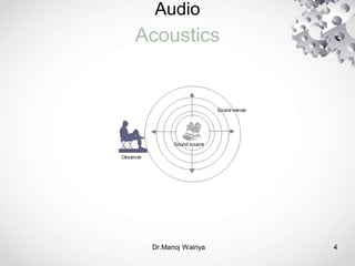
Acoustic energy flowing outwards from its point of generation can
be compared to a spreading wave over the surface of water.
When an object starts vibrating or oscillating rapidly, a part of its
kinetic energy is imparted to the layer of the medium in contact
with the object e.g. the air surrounding a bell.
3.
Audio
Dr.Manoj Wairiya 3
Acoustics
The particles of the medium on receiving the energy starts vibrating on
their own, and in turn help to transfer a portion of their energy to the
next layer of air particles, which also starts vibrating.
This process continues thereby propagating the acoustic energy
throughout the medium. When it reaches our ears it sets the ear-drums
into similar kind of vibration and our brain recognizes this as sound.
Acoustics is the study of sound and is concerned with the generation,
transmission and reception of sound waves. The application of
acoustics in technology is called acoustical engineering.
Audio
Dr.Manoj Wairiya 5
Acoustics
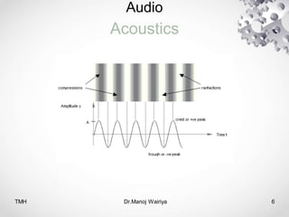
“Sound is an alteration in pressure, particle displacement or
particle velocity propagated in an elastic material” [Olson, 1957].
As sound energy propagates through the material medium, it
sets up alternate regions of compression and rarefaction by
shifting the particles of the medium
This is pictorially represented as a wave, the upper part (i.e. the
crest or positive peak) denoting a compression and the lower
part (i.e. the trough or negative peak) denoting a rarefaction.
Audio
Dr.Manoj Wairiya 7
Acoustics
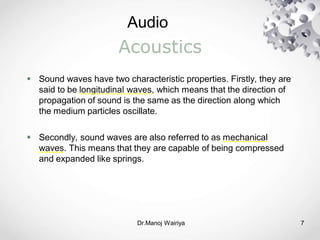
Sound waves have two characteristic properties. Firstly, they are
said to be longitudinal waves, which means that the direction of
propagation of sound is the same as the direction along which
the medium particles oscillate.
Secondly, sound waves are also referred to as mechanical
waves. This means that they are capable of being compressed
and expanded like springs.
8.
Audio
TMH Dr.Manoj Wairiya8
Fundamental Characteristics
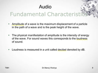
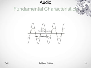
Amplitude of a wave is the maximum displacement of a particle
in the path of a wave and is the peak height of the wave.
The physical manifestation of amplitude is the intensity of energy
of the wave. For sound waves this corresponds to the loudness
of sound.
Loudness is measured in a unit called decibel denoted by dB.
Audio
TMH Dr.Manoj Wairiya10
Fundamental Characteristics
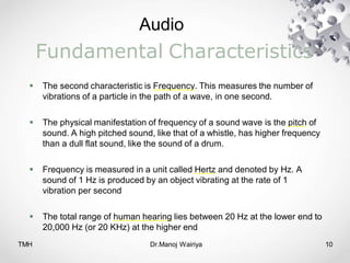
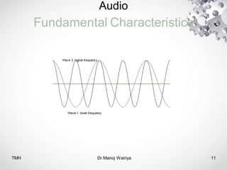
The second characteristic is Frequency. This measures the number of
vibrations of a particle in the path of a wave, in one second.
The physical manifestation of frequency of a sound wave is the pitch of
sound. A high pitched sound, like that of a whistle, has higher frequency
than a dull flat sound, like the sound of a drum.
Frequency is measured in a unit called Hertz and denoted by Hz. A
sound of 1 Hz is produced by an object vibrating at the rate of 1
vibration per second
The total range of human hearing lies between 20 Hz at the lower end to
20,000 Hz (or 20 KHz) at the higher end
TMH Dr.Manoj Wairiya12
Fundamental Characteristics
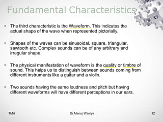
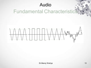
The third characteristic is the Waveform. This indicates the
actual shape of the wave when represented pictorially.
Shapes of the waves can be sinusoidal, square, triangular,
sawtooth etc. Complex sounds can be of any arbitrary and
irregular shape.
The physical manifestation of waveform is the quality or timbre of
sound. This helps us to distinguish between sounds coming from
different instruments like a guitar and a violin.
Two sounds having the same loudness and pitch but having
different waveforms will have different perceptions in our ears.
Audio
TMH Dr.Manoj Wairiya14
Fundamental Characteristics
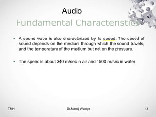
A sound wave is also characterized by its speed. The speed of
sound depends on the medium through which the sound travels,
and the temperature of the medium but not on the pressure.
The speed is about 340 m/sec in air and 1500 m/sec in water.
15.
Audio
TMH Dr.Manoj Wairiya15
Musical Sound & Noise
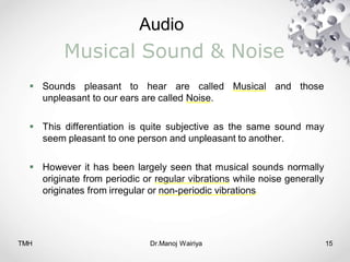
Sounds pleasant to hear are called Musical and those
unpleasant to our ears are called Noise.
This differentiation is quite subjective as the same sound may
seem pleasant to one person and unpleasant to another.
However it has been largely seen that musical sounds normally
originate from periodic or regular vibrations while noise generally
originates from irregular or non-periodic vibrations.
Audio
TMH Dr.Manoj Wairiya17
Musical Sound & Noise
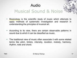
Musicology is the scientific study of music which attempts to
apply methods of systematic investigation and research in
understanding the principles of musical art.
According to its view, there are certain observable patterns in
sound due to which it can be classified as music.
The traditional view of music often associate it with some related
terms like pitch, timbre, intensity, duration, melody, harmony,
rhythm, note and chord.
18.
Audio
TMH Dr.Manoj Wairiya18
Musical Sound & Noise
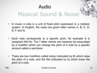
In music a note is a unit of fixed pitch expressed in a notation
system. In English, the notes are given letter names A, B, C, D,
E, F and G.
Each note corresponds to a specific pitch, for example A is
assigned 440 Hz. The 7 letter names can however be associated
by a modifier which can change the pitch of a note by a specific
amount called a semitone.
There are two modifiers called sharp (indicated by #) which raise
the pitch of a note, and the flat (indicated by b) which lower the
pitch of a note.
19.
Audio
Dr.Manoj Wairiya 19
MusicalSound & Noise
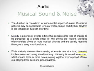
The duration is considered a fundamental aspect of music. Durational
patterns may be specified in terms of meter, tempo and rhythm. Rhythm
is the variation of duration over time.
Melody is a series of events in time that contain some kind of change to
be perceived as a single entity i.e. the events are related. Melodies
often consists of one or more musical phrases and are usually repeated
througout a song in various forms.
While melody stresses the occurring of events one at a time, harmony
implies events occurring simultaneously. Harmony is related to a chord,
which means three or more notes playing together over a period of time
e.g. playing three keys of a piano together.
20.
Audio
Dr.Manoj Wairiya 20
MusicalSound & Noise
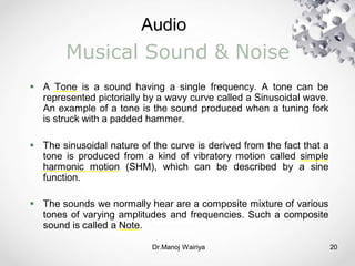
A Tone is a sound having a single frequency. A tone can be
represented pictorially by a wavy curve called a Sinusoidal wave.
An example of a tone is the sound produced when a tuning fork
is struck with a padded hammer.
The sinusoidal nature of the curve is derived from the fact that a
tone is produced from a kind of vibratory motion called simple
harmonic motion (SHM), which can be described by a sine
function.
The sounds we normally hear are a composite mixture of various
tones of varying amplitudes and frequencies. Such a composite
sound is called a Note.
Audio
Dr.Manoj Wairiya 22
MusicalSound & Noise
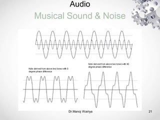
The waveform of a note can be derived from the resultant or sum of all
its tonal components.
The lowest frequency of a note is called the fundamental frequency. All
the other frequencies are called overtones.
Frequencies of some overtones may be integral multiples of the
fundamental frequency. These overtones are called harmonics.
The harmonic nature of periodic waveforms is summarized by the
Fourier Theorem. This theorem states that all complex periodic
waveforms are composed of a harmonic series of sinewaves; complex
waveforms can be synthesized by summing sinewaves
23.
Audio
Dr.Manoj Wairiya 23
MusicalSound & Noise
In acoustics, the term dynamic range is used to mean the ratio of
maximum amplitude of undistorted sound in an audio equipment
like microphone or loudspeaker to the amplitude of the quietest
sound possible.
For digital audio, the dynamic range is synonymous to the signal
to noise ratio (SNR) and is expressed in dB.
It can be shown that increasing the bit-depth of the digital audio
by 1 bit results in its increase in dynamic range by 6 dB
approximately.
24.
Audio
Dr.Manoj Wairiya 24
MusicalSound & Noise
In telecommunication the term crosstalk (XT) is used to indicate
the undesirable effect of a signal transmitted on one channel or
wire of a transmission system on a signal on another wire or
channel.
White noise is a signal that has the same energy or power for
any frequency value i.e. constant power density.
Since a signal physically cannot have power for all frequencies
(which would mean it has infinite energy content), a signal can
be a white noise over a defined frequency range.
25.
Audio
Dr.Manoj Wairiya 25
MusicalSound & Noise
A signal whose power density decreases at the rate of 3 dB per
octave with increasing frequency over a finite frequency range is
called pink noise.
A signal whose power density increases at the rate of 3 dB per
octave with increasing frequency over a finite frequency range is
called blue noise.
A signal whose power density increases at the rate of 6 dB per
octave with increasing frequency over a finite frequency is called
a purple noise.
26.
Audio
Dr.Manoj Wairiya 26
MusicalSound & Noise
A sound which is equally loud at all frequencies is called gray
noise.
A signal whose power density decreases at the rate of 6 dB per
octave with increasing frequency over a finite frequency range is
called brown noise.
A noise capable to canceling other noises and producing silence
is called black noise.
27.
Audio
Dr.Manoj Wairiya 27
Psycho-acoustics
Psycho-acoustics is the branch of acoustics which deals with the
human auditory perception ranging from the biological design of
the ear to the brain’s interpretation of aural information.
A unit for measuring loudness of sound as perceived by the
human ear is Decibel.
It involves comparing the intensity of a sound with the faintest
sound audible by the human ear and expressing the ratio as a
logarithmic value.
28.
Audio
TMH Dr.Manoj Wairiya28
Psycho-acoustics
Power in dB = 10 log10 (power A / power B)
or
Power in dB = 20 log10 (amplitude A / amplitude B)
The second relation is derived from the fact that the power or
intensity of sound energy is proportional to the square of the
amplitude of the sound wave.
The softest audible sound has a power of about 10-12 watt/sq.
meter and the loudest sound we can hear (also known as
threshold of pain), is about 1 watt/sq. meter, giving a total range
of human hearing as 120 dB.
29.
Audio
Psycho-acoustics
TMH Dr.Manoj Wairiya29
There are two popular ways to make acoustical measurements:
the direct method and the comparison method.
The direct method proposes measuring a set of environmental
factors like temperature, humidity, viscosity, echo timings etc.
and using them in appropriate relations to compute sound energy
levels.
The comparison method is conducted by measuring sound
pressure levels of a reference sound of known energy levels and
comparing those pressure levels with the sound being measured.
29
30.
Audio
Psycho-acoustics
Dr.Manoj Wairiya 30
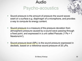
Sound pressure is the amount of pressure the sound waves
exert on a surface e.g. diaphragm of a microphone, and provides
a way to compute its energy content.
Sound pressure is a measure of the pressure deviation from
atmospheric pressure caused by a sound wave passing through
a fixed point, and expressed in a unit called Pascals (1 Pa = 1
Newtons/m2).
Sound pressure level (SPL) is the sound pressure expressed in
decibels, based on a reference sound pressure of 20 µPa.
31.
Audio
Psycho-acoustics
Dr.Manoj Wairiya 31
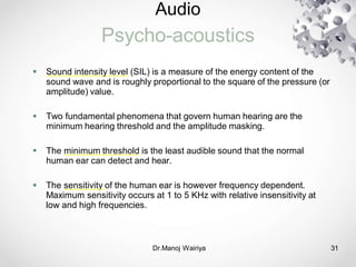
Sound intensity level (SIL) is a measure of the energy content of the
sound wave and is roughly proportional to the square of the pressure (or
amplitude) value.
Two fundamental phenomena that govern human hearing are the
minimum hearing threshold and the amplitude masking.
The minimum threshold is the least audible sound that the normal
human ear can detect and hear.
The sensitivity of the human ear is however frequency dependent.
Maximum sensitivity occurs at 1 to 5 KHz with relative insensitivity at
low and high frequencies.
32.
Audio
Psycho-acoustics
Dr.Manoj Wairiya 32
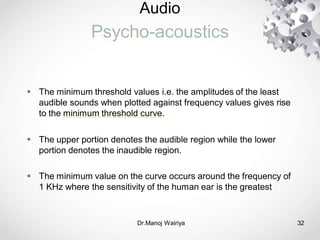
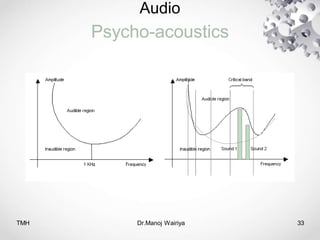
The minimum threshold values i.e. the amplitudes of the least
audible sounds when plotted against frequency values gives rise
to the minimum threshold curve.
The upper portion denotes the audible region while the lower
portion denotes the inaudible region.
The minimum value on the curve occurs around the frequency of
1 KHz where the sensitivity of the human ear is the greatest
Audio
Psycho-acoustics
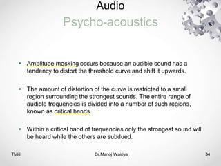
TMH Dr.Manoj Wairiya34
Amplitude masking occurs because an audible sound has a
tendency to distort the threshold curve and shift it upwards.
The amount of distortion of the curve is restricted to a small
region surrounding the strongest sounds. The entire range of
audible frequencies is divided into a number of such regions,
known as critical bands.
Within a critical band of frequencies only the strongest sound will
be heard while the others are subdued.
35.
Audio
Audio Systems
Dr.Manoj Wairiya35
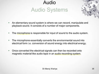
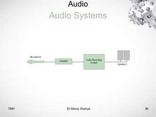
An elementary sound system is where we can record, manipulate and
playback sound. It consists of a number of major components.
The microphone is responsible for input of sound to the audio system.
The microphone essentially converts the environmental sound into
electrical form i.e. conversion of sound energy into electrical energy.
Once converted the electrical signals can then be recorded onto
magnetic material like audio tape in an audio recording system.
Audio
Audio Systems
Dr.Manoj Wairiya37
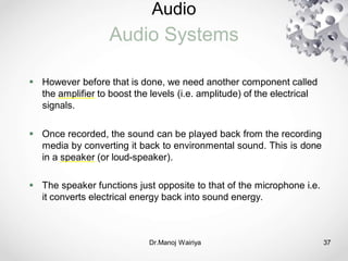
However before that is done, we need another component called
the amplifier to boost the levels (i.e. amplitude) of the electrical
signals.
Once recorded, the sound can be played back from the recording
media by converting it back to environmental sound. This is done
in a speaker (or loud-speaker).
The speaker functions just opposite to that of the microphone i.e.
it converts electrical energy back into sound energy.
38.
Audio
Microphones
Dr.Manoj Wairiya 38
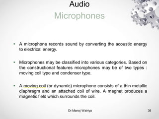
A microphone records sound by converting the acoustic energy
to electrical energy.
Microphones may be classified into various categories. Based on
the constructional features microphones may be of two types :
moving coil type and condenser type.
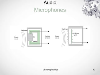
A moving coil (or dynamic) microphone consists of a thin metallic
diaphragm and an attached coil of wire. A magnet produces a
magnetic field which surrounds the coil.
39.
Audio
Microphones
Dr.Manoj Wairiya 39
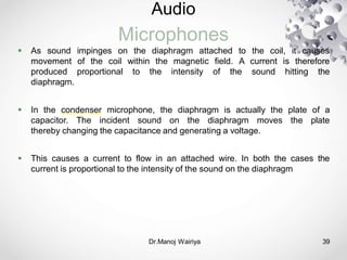
As sound impinges on the diaphragm attached to the coil, it causes
movement of the coil within the magnetic field. A current is therefore
produced proportional to the intensity of the sound hitting the
diaphragm.
In the condenser microphone, the diaphragm is actually the plate of a
capacitor. The incident sound on the diaphragm moves the plate
thereby changing the capacitance and generating a voltage.
This causes a current to flow in an attached wire. In both the cases the
current is proportional to the intensity of the sound on the diaphragm
Audio
Microphones
TMH Dr.Manoj Wairiya41
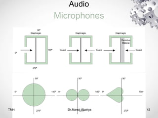
Based on the directional properties, microphones may be
classified into three types : omni-directional, bi-directional and
uni-directional.
An omni-directional microphone is equally sensitive to sounds
coming from all direction. These are used to record sound
coming from multiple sources.
A bi-directional microphone is sensitive to sounds coming from
two directions : the front and rear. It is used to record two
sources of sound simultaneously
42.
Audio
Microphones
Dr.Manoj Wairiya 42
A uni-directional microphone is designed to record sound from a
single source e.g. a single individual speaking.
Its construction is similar to that of the bi-directional one, with a
single exception. On the rear side of the microphone is a
resistive material like foam or cloth near the diaphragm.
The polar plot of a microphone is a graph plotting the output level
of the microphone against the angle at which the incident sound
was produced.
Audio
Amplifier
Dr.Manoj Wairiya 44
In general, amplifier is the name given to a device in which a
varying input signal controls a flow of energy to produce an
output signal that varies in the same way but has a larger
amplitude.
Ampliers used in audio processing are electronic in nature and
use a series of transistors as their principal components,
connected in a printed circuit board.
The ratio of the output amplitude to the input amplitude is known
as the gain of the amplifier.
45.
Audio
Amplifier
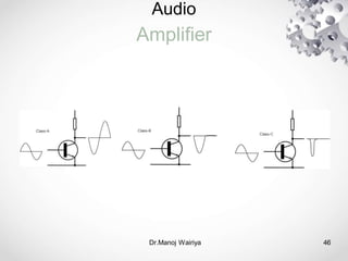
TMH Dr.Manoj Wairiya45
Class-A amplifiers use 100% of the input cycle for generating the
output. They are not very efficient, a theoretical maximum of 50%
effciency is obtained and are usually used for small signal levels.
Class-B amplifiers only use half of the input cycle for
amplification. Though they produce a large amount of distortion,
these amplifiers are more efficient than Class-A because the
amplifying element is switched off during half of the cycle.
Class-C amplifiers use less than half of the input cycle for
amplification. Though they produce a huge amount of distortion,
they are the most efficient.
Audio
Amplifier
Dr.Manoj Wairiya 47
Since the amplifying elements are essentially non-linear,
distortion in the output wave is an inherant problem that needs to
be dealt with. The distortion is perceived as noise in the percived
sound.
One way of reducing distortion further is to introduce a negative
feedback. This involves feeding back a portion of the output back
to the input so that it is subtracted from the original input.
The negative distortions combine with the positive distortions
produced subsequently by the amplifier with the result that the
output signal is more or less linear.
48.
Audio
Amplifier
TMH Dr.Manoj Wairiya48
Class-D digital ampliers use a series of transistors as switches.
The input signal is sampled and converted to digital pulses using
an ADC. The pulses are then used to switch the transistors on
and off.
Class-E digital amplifiers uses pulse width modulation (PWM) to
produce output waves whose widths are proportional to the
desired amplitudes. This requires a single transistor for switching
and is therefore cheaper than the others.
49.
Audio
Loudspeaker
Dr.Manoj Wairiya 49
A loudspeaker is a device that converts electrical energy back to
acoustic energy and therefore functions just opposite to that of a
microphone.
Electrical signals from an amplifier or a playback system is fed to the
loudspeaker based on which it generates environmental sound whose
loudness is proportional to the amplitude of the source electrical signal.
Loudspeakers are based on the traditional design of a wire coil and a
paper cone. A cone made of paper or fibre, known as the diaphragm, is
attached to a coil of wire, kept near a permanent magnet.
50.
Audio
Loudspeaker
TMH Dr.Manoj Wairiya50
When current from a source system is passed through the coil, a
magnetic field is generated around the coil. This field interacts with the
magnetic field of the permanent magnet generating vibrating forces
which oscillate the diaphragm.
Due to resonance characteristics, the physical properties of a vibrating
element makes it suitable to reproduce sounds of a specific frequency
range, instead of the entire 20 KHz human audible range.
Thicker and heavier diaphragms are suitable for low frequency sounds
while thinner and lighter elements are suitable for high frequencies.
51.
Audio
Loudspeaker
TMH Dr.Manoj Wairiya51
Thus to get a good response over the entire audible range, a
loudspeaker is divided into smaller units each of which are tuned
for a small frequency range.
These units are called woofers which handle low frequencies,
mid-range for handling middle frequencies and tweeter for
handling high frequencies.
52.
Audio
Loudspeaker
TMH Dr.Manoj Wairiya52
Woofers usually handle the frequency
range from 20 Hz to 400 Hz. Such low
frequency sounds are known as bass
Mid-range speakers are designed to
handle frequency ranges between 400 Hz
and 4KHz.
Tweeters are designed to handle
frequency ranges between 4 KHz and
20 KHz. Such high frequency sounds are
53.
Audio
Mixer
Dr.Manoj Wairiya 53
In professional studios multiple microphones may be used to
record multiple tracks of sound at a time e.g. recording
performance of an orchestra.
A device called an audio mixer is used to record these individual
tracks and edit them separately. Each of these tracks a number
of controls for adjusting the volume, tempo (speed of playback),
mute etc.
54.
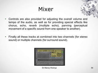
Mixer
Controls arealso provided for adjusting the overall volume and
tempo of the audio, as well as for providing special effects like
chorus, echo, reverb (multiple echo), panning (perceptual
movement of a specific sound from one speaker to another).
Finally all these tracks at combined into two channels (for stereo
sound) or multiple channels (for surround sound).
Dr.Manoj Wairiya 54
55.
Audio
Digital Audio
Dr.Manoj Wairiya55
As per the postulates of the Nyquist's sampling theory sampling
frequency needs to be twice the input frequency.
We know that the full range of human hearing ranges from 20 Hz
to 20 KHz. Thus to be able to represent the entire range digitally,
minimum sampling frequencies should be around 40 KHz.
In practical systems a slightly higher frequency in the range of 44
to 48 KHz is employed during sampling.
For practical purposes, bit depths of 8-bits and 16-bits are
sufficient.
56.
Audio
Digital Audio
TMH Dr.ManojWairiya 56
Aliasing is a consequence of violating the sampling theorem. The highest
audio frequency in a sampling system must be less than or equal to the
Nyquist frequency.
If the audio frequency is greater than the Nyquist frequency
erroneous signals can appear within the audio bandwidth. This effect is
called aliasing.
For an audio-CD sampling is done at 44.1 KHz, 16-bit resolution and
stereo mode. A 1 minute clip occupies a file size of about
• 10.5 MB
56
57.
Audio
Digital Audio
Dr.Manoj Wairiya57
Streaming audio is used for downloading files on the Internet.
The music begins to play as soon as a buffer memory on the
receiving device fills up, while the remaining portion of the audio
continues to be downloaded in the background.
A popular type of streaming format is RealNetwork’s RealAudio.
RealAudio files can be coded at a variety of bit rates
Apple’s QuickTime software offers several compression options
for music and speech applications, for both downloading and
streaming.
58.
Audio
Digital Audio
Dr.Manoj Wairiya58
High fidelity or hi-fi is a term describing the reproduction of sound and
image almost identical to the original in quality i.e. with minimum
distortion and noise.
Technically the term meant that the system conformed to the RIAA
equalization specifications.
This is a specification established by the Recording Industry Association
of America (RIAA) for the correct playback of vinyl records, based on
applying equalization.
Equalization is essentially a process of modifying the frequency
envelope of a sound.
59.
Audio
Synthesizers
Dr.Manoj Wairiya 59
Synthesizers are
generate digital samples of sounds of
electronic instruments which allow us to
various instruments
synthetically i.e. without the actual instrument being present.
FM Synthesizers generate sound by combining elementary
sinusoidal tones to build up a note having the desired waveform.
The basis for this method is the Fourier Transform using which a
waveform can be decomposed into its elementary sinusoidal
components of varying amplitude and frequency.
60.
Audio
Synthesizers
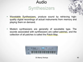
Wavetable Synthesizers,produce sound by retrieving high-
quality digital recordings of actual instruments from memory and
playing them on demand.
Modern synthesizers are generally of wavetable type. The
sounds associated with synthesizers are called patches, and the
collection of all patches is called the Patch Map.
Dr.Manoj Wairiya 60
61.
Audio
Synthesizers
61
The polyphonyof a synthesizer refers to its ability to play more
than one note at a time. Polyphony is generally measured or
specified as a number of notes or voices.
Pressing five keys on the keyboard of a synthesizer which was
polyphonic with four voices of polyphony would, in general,
produce four notes
Dr.Manoj Wairiya
62.
Audio
MIDI
Dr.Manoj Wairiya 62
The Musical Instrument Digital Interface (MIDI) is a protocol or
set of rules for connecting digital synthesizers to personal
computers.
Much in the same way that two computers communicate via
modems, two synthesizers communicate via MIDI.
Technical and administrative related to MIDI
specifications are
issues
the MIDI Manufacturers
(MMA)
handled by
and Japan MIDI Standards
Committee
Association
(JMSC).
63.
Audio
MIDI
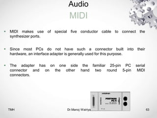
MIDI makesuse of special five conductor cable to connect the
synthesizer ports.
Since most PCs do not have such a connector built into their
hardware, an interface adapter is generally used for this purpose.
The adapter has on one side the familiar 25-pin PC serial
connector and on the other hand two round 5-pin MIDI
connectors.
TMH Dr.Manoj Wairiya 63
64.
Audio
MIDI
TMH Dr.Manoj Wairiya64
The MIDI messages constitute an entire music description language
in binary form. Each word describing an action of musical performance
is assigned a specific binary code.
The messages are transmitted as a unidirectional asynchronous bit
stream at 31.25 Kbits/sec.
The single physical MIDI Channel is divided into 16 logical
channels by the inclusion of a 4 bit Channel number within many of the
MIDI messages.
65.
Audio
MIDI
Dr.Manoj Wairiya 65
The MIDI specifications made provisions to save synthesizer
audio in a separate file format called MIDI files. MIDI files are
extremely compact as compared to WAV files.
This is because the MIDI file does not contain the sampled audio
data, it contains only the instructions needed by a synthesizer to
play the sounds.
These instructions are in the form of MIDI messages, which
instruct the synthesizer which sounds to use, which notes to
play, and how loud to play each note. The actual sounds are
then generated by the synthesizer
66.
Audio
MIDI
Dr.Manoj Wairiya 66
MIDI based instructions are called messages. These messages
carry the information on what instruments to play in which
channel and how to play them.
Each message consists of two or three bytes : the first is the
Status Byte which contains the function or operation to be
performed and the channel number which is to be affected.
The other two bytes are called Data Bytes and they provide
additional parameters on how to perform the indicated operation.
67.
Audio
MIDI
TMH Dr.Manoj Wairiya67
Channel messages are those which apply
to a specific Channel, and the Channel
number is included in the status byte for
these messages.
System messages are not Channel
specific, and no Channel number is
indicated in their status bytes.
Channel Voice Messages carry musical
performance data, and these
68.
Audio
MIDI
Dr.Manoj Wairiya 68
Channel Mode Messages affect the way a synthesizer responds to MIDI
data. Controller number 121 is used to reset all controllers. Controller
number 122 is used to enable or disable Local Control
MIDI System Messages are classified as being System Common
Messages, System Real Time Messages, or System Exclusive
Messages.
System Common Messages are intended for all receivers in the system.
System Real Time messages are used for synchronization between
clock-based MIDI components. System Exclusive messages include a
Manufacturer's Identification (ID) code, and are used to transfer any
number of data bytes in a format specified by the referenced
manufacturer.
68
69.
Audio
Dr.Manoj Wairiya 69
MIDI
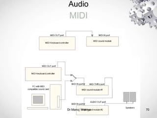
The MIDI interface on a MIDI instrument will generally include three
different MIDI connectors, labeled IN, OUT, and THRU.
A MIDI controller is a device which is played as an instrument, like a
keyboard, and it translates the performance into a MIDI data stream in
real time (as it is played).
A MIDI sequencer is a device which allows MIDI data sequences to be
captured, stored, edited, combined, and replayed. The MIDI data output
from a MIDI controller or sequencer is transmitted via the devices' MIDI
OUT connector.
The recipient of this MIDI data stream is commonly a MIDI sound
generator or sound module, which will receive MIDI messages at its
MIDI IN connector, and respond to these messages by playing sounds.
Audio
Dr.Manoj Wairiya 71
MIDI
Initially there was no standard for the relationship of patch
numbers to specific sounds for synthesizers.
Thus, a MIDI sequence might produce different sounds when
played on different synthesizers, even though the synthesizers
had comparable types of sounds.
The General MIDI (GM) Specification defines a set of general
capabilities for General MIDI Instruments. The General MIDI
Specification includes the definition of a General MIDI Sound Set
(a patch map)
72.
Audio
Dr.Manoj Wairiya 72
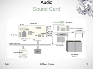
SoundCard
The sound card is an expansion board in your multimedia PC which
interfaces with the CPU via slots on the mother-board.
Externally it is connected to speakers for playback of sound. Other than
playback the sound card is also responsible for digitizing, recording and
compressing the sound files.
Memory Banks
This depicts the local memory of the sound card for storing audio data
during digitization and playback of sound files.
DSP
Newer sound cards makes use of open architecture which uses a multi-
purpose digital signal processor (DSP) as the main controller of all audio
signals in the digital domain.
73.
Audio
Sound Card
Dr.Manoj Wairiya73
DAC/ADC
The digital-to-analog and analog-to-digital converters for
digitizing analog sound and reconverting digital sound files to
analog form for playback.
WaveTable/FM Synthesizer Chip
A MIDI synthesizer chip is necessary to recognize MIDI
sequences recorded onto the disk or input from an external
synthesizer. The chip can either be the FM type or wavetable
type.
74.
Audio
Sound Card
Dr.Manoj Wairiya74
CD Interface
This is the internal connection between the CD drive of the PC
and the sound card. This allows connecting a CD-ROM drive to
the sound card.
16-bit ISA connector
Interface for exchanging audio data between the CPU and sound
card.
75.
Audio
Sound Card
Dr.Manoj Wairiya75
CD Interface
This is the internal connection between the CD drive of the PC
and the sound card. This allows connecting a CD-ROM drive to
the sound card.
16-bit ISA connector
Interface for exchanging audio data between the CPU and sound
card.
76.
Audio
Sound Card
TMH Dr.ManojWairiya 76
Line Out
Output port for connecting to external recording devices like a
cassette player or an external amplifier.
MIC
Input port for feeding audio data to the sound card through a
microphone connected to it.
Line In
Input port for feeding audio data from external CD/cassette
players for recording or playback.
77.
Audio
Sound Card
TMH Dr.ManojWairiya 77
MIDI
Input port for interfacing with an external synthesizer. Using this
connection, MIDI songs can be composed on the PC using
software and then can be sent to the sound modules of external
synthesizers for playback.
TMH Dr.Manoj Wairiya79
Sound Card
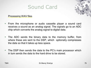
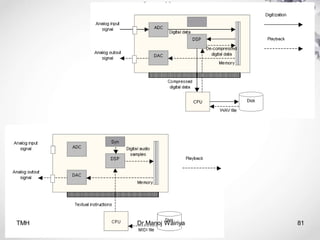
Processing WAV files
From the microphone or audio cassette player a sound card
receives a sound as an analog signal. The signals go to an ADC
chip which converts the analog signal to digital data.
The ADC sends the binary data to the memory buffer, from
where these are sent to the DSP, which optionally compresses
the data so that it takes up less space.
The DSP then sends the data to the PC’s main processor which
in turn sends the data to the hard drive to be stored.
80.
Dr.Manoj Wairiya 80
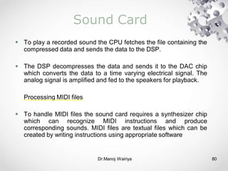
SoundCard
To play a recorded sound the CPU fetches the file containing the
compressed data and sends the data to the DSP.
The DSP decompresses the data and sends it to the DAC chip
which converts the data to a time varying electrical signal. The
analog signal is amplified and fed to the speakers for playback.
Processing MIDI files
To handle MIDI files the sound card requires a synthesizer chip
which can recognize MIDI instructions and produce
corresponding sounds. MIDI files are textual files which can be
created by writing instructions using appropriate software
Audio
Dr.Manoj Wairiya 82
AudioTransmission
The AES/EBU (Audio Engineering Society / European Broadcasting
Union) is a standard for carrying digital audio signals between devices
and components published in 1992 and subsequently revised a number
of times.
The standard specifies the format for serial digital transmission of two
channels of periodically sampled and uniformly quantized audio signals
on a single twisted wire pair.
The Sony Philips Digital Interconnect Format (SPDIF) is a standard for
transmission of digital audio signals between devices and components.
It was developed from the AES/EBU standard used in DAT systems. It
is almost identical at the protocol level, however the physical connectors
are different.
83.
Audio
TMH Dr.Manoj Wairiya83
Audio Transmission
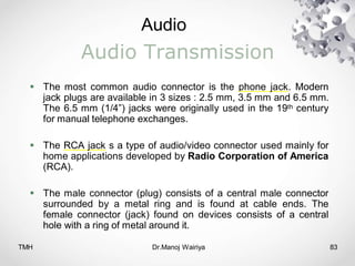
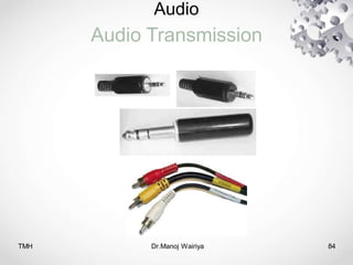
The most common audio connector is the phone jack. Modern
jack plugs are available in 3 sizes : 2.5 mm, 3.5 mm and 6.5 mm.
The 6.5 mm (1/4”) jacks were originally used in the 19th century
for manual telephone exchanges.
The RCA jack s a type of audio/video connector used mainly for
home applications developed by Radio Corporation of America
(RCA).
The male connector (plug) consists of a central male connector
surrounded by a metal ring and is found at cable ends. The
female connector (jack) found on devices consists of a central
hole with a ring of metal around it.
Audio
TMH Dr.Manoj Wairiya85
Audio Recording
A gramophone record or phonograph record (often simply
record) is an analogue sound recording medium: a flat disc
rotating at a constant angular velocity, with inscribed spiral
grooves in which a stylus or needle rides.
Wire recording is a type of analogue audio storage. The
recording is made onto thin wire. This can have a duration of
many hours.
Reel-to-reel or open reel tape recording refers to the form of
magnetic tape audio recording in which the recording medium is
held on a reel, rather than being securely contained within a
cassette.
86.
Audio
Dr.Manoj Wairiya 86
AudioRecording
The 8-track cartridge is a now-obsolete audio storage magnetic
tape cartridge technology, popular during the 1960s and 1970s.
The cartridge was designed in 1956 around a single reel with the
two ends of the plastic recording tape joined with a piece of
conductive foil tape to make one continuous loop.
The compact audio cassette audio storage medium was
introduced by Philips in 1963. It originally consisted of a length of
magnetic tape from BASF inside a protective plastic shell. Four
tracks are available on the tape, giving two stereo tracks – one
for playing with the cassette inserted with its 'A' side up, and the
other with the 'B' side up
87.
Audio
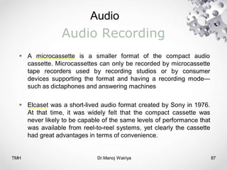
TMH Dr.Manoj Wairiya87
Audio Recording
A microcassette is a smaller format of the compact audio
cassette. Microcassettes can only be recorded by microcassette
tape recorders used by recording studios or by consumer
devices supporting the format and having a recording mode—
such as dictaphones and answering machines
Elcaset was a short-lived audio format created by Sony in 1976.
At that time, it was widely felt that the compact cassette was
never likely to be capable of the same levels of performance that
was available from reel-to-reel systems, yet clearly the cassette
had great advantages in terms of convenience.
88.
Audio
Dr.Manoj Wairiya 88
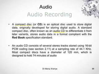
AudioRecording
A compact disc (or CD) is an optical disc used to store digital
data, originally developed for storing digital audio. A standard
compact disc, often known as an audio CD to differentiate it from
later variants, stores audio data in a format compliant with the
Red Book specification standard.
An audio CD consists of several stereo tracks stored using 16-bit
PCM coding (see section 2.11) at a sampling rate of 44.1 KHz.
Most compact discs have a diameter of 120 mm, which is
designed to hold 74 minutes of audio.
89.
Audio
TMH Dr.Manoj Wairiya89
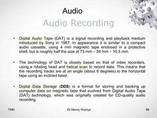
Audio Recording
Digital Audio Tape (DAT) is a signal recording and playback medium
introduced by Sony in 1987. In appearance it is similar to a compact
audio cassette, using 4 mm magnetic tape enclosed in a protective
shell, but is roughly half the size at 73 mm × 54 mm × 10.5 mm.
The technology of DAT is closely based on that of video recorders,
using a rotating head and helical scan to record data. This means that
the recording tracks are at an angle (about 6 degrees) to the horizontal
tape using an inclined head.
Digital Data Storage (DDS) is a format for storing and backing up
computer data on magnetic tape that evolved from Digital Audio Tape
(DAT) technology, which was originally created for CD-quality audio
recording.
90.
Audio
Dr.Manoj Wairiya 90
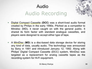
AudioRecording
Digital Compact Cassette (DCC) was a short-lived audio format
created by Philips in the early 1990s. Pitched as a competitor to
Minidisc (MD), it never caught on with the general public. It
shared its form factor with standard analogue cassettes, and
players were designed to accept either type of tape.
A MiniDisc (MD) is a disc-based data storage device for storing
any kind of data, usually audio. The technology was announced
by Sony in 1991 and introduced January 12, 1992. Along with
Philips' Digital Compact Cassette (DCC) system, MiniDisc was
targeted as a replacement for analog cassette tapes as the
recording system for Hi-Fi equipment.
91.
Audio
Dr.Manoj Wairiya 91
Codingand File Formats
WAV is the format for sampled sounds defined by Microsoft for
use with Windows. It is an expandable format which supports
multiple data formats and compression schemes. It is used for
uncompressed 8-, 12- and 16-bit audio files both mono and
multi-channel, at a variety of sampling rates including 44.1 KHz.
Audio Interchange File Format (AIFF) is a file format standard
used for storing audio data on PCs. The format was co-
developed by Apple based on Electronic Arts Interchange File
Format (IFF) and is most commonly used on Apple Macintosh
computer systems.
92.
Dr.Manoj Wairiya 92
Codingand File Formats
AU is developed by Sun Microsystem, this audio file format
consists of a header of six 32-bit words which defines the
metadata about the actual audio data following it.
MP3 is a highly compressed audio format providing almost CD-
quality sound. MP3 can compress a typical song into 5 MB for
which it is extensively used for putting audio content on the
Internet. The files can be coded at a variety of bit rates, and
provides good results at bit rates of 96 kbps.
VOC is used with Sound Blaster sound cards. Sound upto 16-bit
stereo is supported along with compressed formats.

![Audio
Dr.Manoj Wairiya 5
Acoustics
“Sound is an alteration in pressure, particle displacement or
particle velocity propagated in an elastic material” [Olson, 1957].
As sound energy propagates through the material medium, it
sets up alternate regions of compression and rarefaction by
shifting the particles of the medium
This is pictorially represented as a wave, the upper part (i.e. the
crest or positive peak) denoting a compression and the lower
part (i.e. the trough or negative peak) denoting a rarefaction.](https://image.slidesharecdn.com/chapter071-250813194906-de4609e8/85/ChapteR012372321DFGDSFGDFGDFSGDFGDFGDFGSDFGDFGFD-5-320.jpg)