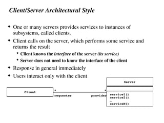
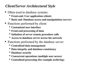
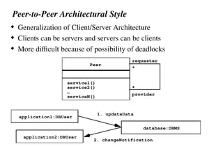
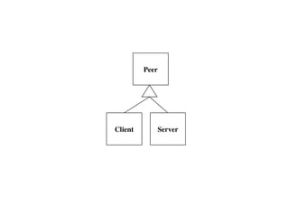
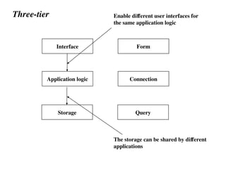
Chapter 6
System Design: Decomposing the system
What is system design
 Decompose the system into smaller subsystems
 Define the design goals of the project
 Select strategies for building the system
 Hardware/software strategy
 Persistent data management strategy
 Global control flow
 Access control policy
 Handling of boundary conditions
 The result of system design is a model that includes a
subsystem decomposition and a clear description of each of
these strategies
System Design
System Design
2. System
Layers/Partitions
Cohesion/Coupling
5. Data
1. Design Goals
Definition
Trade-offs
4. Hardware/
Special purpose
Software
Buy or Build Trade-off
Allocation
Connectivity
3. Concurrency
Data structure
Persistent Objects
Files
Databases
Management
Access control
Security
6. Global
Resource Handling
8. Boundary
Conditions
Initialization
Termination
Failure
Decomposition
Mapping
7. Software
Control
Identification of
Threads
Monolithic
Event-Driven
Threads
Conc. Processes
Overview
System Design I (Today)
0. Overview of System Design
1. Subsystem Decomposition
System Design II: Addressing Design Goals (next lecture)
2. Design Goals
3. Concurrency
4. Hardware/Software Mapping
5. Persistent Data Management
6. Global Resource Handling and Access Control
7. Software Control
8. Boundary Conditions
How to use the results from the Requirements
Analysis for System Design
 Nonfunctional requirements =>
 Activity 1: Design Goals Definition
 Functional model =>
 Activity 2: System decomposition (Selection of subsystems based on
functional requirements, cohesion, and coupling)
 Object model =>
 Activity 4: Hardware/software mapping
 Activity 5: Persistent data management
 Dynamic model =>
 Activity 3: Concurrency
 Activity 6: Global resource handling
 Activity 7: Software control
 Subsystem Decomposition
 Activity 8: Boundary conditions
Section 2. System Decomposition
 Subsystem (UML: Package)
 Collection of classes, associations, operations, events and
constraints that are interrelated
 Seed for subsystems: UML Objects and Classes.
 (Subsystem) Service:
 Group of operations provided by the subsystem
 Seed for services: Subsystem use cases
 Service is specified by Subsystem interface:
 Specifies interaction and information flow from/to subsystem
boundaries, but not inside the subsystem.
 Should be well-defined and small.
 Often called API: Application programmer’s interface, but this
term should used during implementation, not during System
Design
Services and Subsystem Interfaces
 Service: A set of related operations that share a common
purpose
 Notification subsystem service:
 LookupChannel()
 SubscribeToChannel()
 SendNotice()
 UnscubscribeFromChannel()
 Services are defined in System Design
 Subsystem Interface: Set of fully typed related operations.
 Subsystem Interfaces are defined in Object Design
 Also called application programmer interface (API)
Definition: Subsystem Interface Object
 A Subsystem Interface Object provides a service
This is the set of public methods provided by the
subsystem
The Subsystem interface describes all the methods of the
subsystem interface object
System as a set of subsystems communicating via a
software bus
Authoring
Modeling
Augmented
Reality
Workorder
Repair
Inspection
Workflow
A Subsystem Interface Object publishes the service (= Set of public methods)
provided by the subsystem
Choosing Subsystems
 Criteria for subsystem selection: Most of the interaction should
be within subsystems, rather than across subsystem boundaries
(High cohesion).
 Does one subsystem always call the other for the service?
 Which of the subsystems call each other for service?
 Primary Question:
 What kind of service is provided by the subsystems (subsystem
interface)?
 Secondary Question:
 Can the subsystems be hierarchically ordered (layers)?
Subsystem Decomposition Example
Is this the right
Decomposition?
Modeling
Authoring
Workorder Repair
Inspection
Augmented
Reality
Workflow
Coupling and Cohesion
 Goal: Reduction of complexity while change occurs
 Cohesion measures the dependence among classes within a subsystem
 High cohesion: The classes in the subsystem perform similar tasks and are
related to each other (via associations)
 Low cohesion: Lots of miscellaneous and auxiliary classes, no associations
 Coupling measures dependencies between subsystems
 High coupling: Changes to one subsystem will have high impact on the other
subsystem (change of model, massive recompilation, etc.)
 Low coupling: A change in one subsystem does not affect any other subsystem
 Subsystems should have as maximum cohesion and minimum coupling as
possible:
 How can we achieve high cohesion?
 How can we achieve loose coupling?
Our class as a system, graduate/undergraduate as subsystem,
group as subsystems
A 3-layered Architecture
Repair Inspection Authoring
Augmented
Reality
Workflow
Modeling
Partitions and Layers
Partitioning and layering are techniques to achieve low
coupling.
A large system is usually decomposed into subsystems using
both, layers and partitions.
 Partitions vertically divide a system into several independent
(or weakly-coupled) subsystems that provide services on the
same level of abstraction.
 A layer is a subsystem that provides subsystem services to a
higher layers (level of abstraction)
 A layer can only depend on lower layers
 A layer has no knowledge of higher layers
Take our class as an example again. Partitions – groups, layers –
classroom infrastructure and classes
F:Subsystem
E:Subsystem G:Subsystem
D:Subsystem
C:Subsystem
B:Subsystem
A: Subsystem Layer 1
Layer 2
Layer 3
Subsystem Decomposition into Layers
 Subsystem Decomposition Heuristics:
 No more than 7+/-2 subsystems
 More subsystems increase cohesion but also complexity (more
services)
 No more than 4+/-2 layers, use 3 layers (good)
Relationships between Subsystems
 Layer relationship
 Layer A “Calls” Layer B (runtime)
 Layer A “Depends on” Layer B (“make” dependency, compile
time)
 Partition relationship
 The subsystem have mutual but not deep knowledge about each
other
 Partition A “Calls” partition B and partition B “Calls” partition A
Virtual Machine
 Dijkstra: T.H.E. operating system (1965)
 A system should be developed by an ordered set of virtual machines, each built in terms of the
ones below it.
VM4
VM3
VM2
VM1
C1
attr
opr
C1
attr
opr
C1
attr
opr
C1
attr
opr
C1
attr
opr
C1
attr
opr
C1
attr
opr
C1
attr
opr
Problem
Existing System
Virtual Machine
 A virtual machine is an abstraction
 It provides a set of attributes and operations.
 A virtual machine is a subsystem
 It is connected to higher and lower level virtual machines by
"provides services for" associations.
 Virtual machines can implement two types of software
architecture
 Open and closed architectures.
Closed Architecture (Opaque Layering)
 Any layer can only invoke
operations from the
immediate layer below
 Design goal: High
maintainability, flexibility
VM4
VM3
VM2
VM1
C1
attr
op
C1
attr
op
C1
attr
op
C1
attr
op
C1
attr
op
C1
attr
op
C1
attr
op
C1
attr
op
C1
attr
op
Open Architecture (Transparent Layering)
 Any layer can invoke operations
from any layers below
 Design goal: Runtime efficiency
VM4
VM3
VM2
VM1
C1
attr
op
C1
attr
op
C1
attr
op
C1
attr
op
C1
attr
op
C1
attr
op
C1
attr
op
C1
attr
op
C1
attr
op
Properties of Layered Systems
 Layered systems are hierarchical. They are desirable because
hierarchy reduces complexity (by low coupling).
 Closed architectures are more portable.
 Open architectures are more efficient.
 If a subsystem is a layer, it is often called a virtual machine.
G: Op. System
D: File System
A: Debugger
Software Architectural Styles
 Subsystem decomposition
 Identification of subsystems, services, and their relationship to each
other.
 Specification of the system decomposition is critical.
 Patterns for software architecture
 Repository
 Client/Server
 Peer-To-Peer
 Model/View/Controller
 Pipes and Filters
Repository Architectural Style (Blackboard
Architecture, Hearsay II Speech Recognition System)
 Subsystems access and modify data from a single data structure
 Subsystems are loosely coupled (interact only through the
repository)
 Control flow is dictated by central repository (triggers) or by
the subsystems (locks, synchronization primitives)
Subsystem
Repository
createData()
setData()
getData()
searchData()
Examples of Repository Architectural Style
 Hearsay II speech
understanding system
(“Blackboard
architecture”)
 Database Management
Systems
 Modern Compilers
LexicalAnalyzer
SyntacticAnalyzer
SemanticAnalyzer
CodeGenerator
Compiler
SyntacticEditor
ParseTree SymbolTable
Repository
SourceLevelDebugger
Optimizer
Model/View/Controller
 Subsystems are classified into 3 different types
 Model subsystem: Responsible for application domain knowledge
 View subsystem: Responsible for displaying application domain
objects to the user
 Controller subsystem: Responsible for sequence of interactions with
the user and notifying views of changes in the model.
 MVC is a special case of a repository architecture:
 Model subsystem implements the central datastructure, the
Controller subsystem explicitly dictate the control flow
Controller
Model
subscriber
notifier
initiator
*
repository
1
1
*
View
Example of a File System Based on the MVC
Architectural Style
Sequence of Events (Collaborations)
:Controller
:InfoView
:Model
2.User types new filename
1. Views subscribe to event
3. Request name change in model
4. Notify subscribers
5. Updated views
:FolderView
Another Example: A multi-user simulation game system
Client/Server Architectural Style
 One or many servers provides services to instances of
subsystems, called clients.
 Client calls on the server, which performs some service and
returns the result
 Client knows the interface of the server (its service)
 Server does not need to know the interface of the client
 Response in general immediately
 Users interact only with the client
Client
Server
service1()
service2()
serviceN()
…
*
*
requester provider
Client/Server Architectural Style
 Often used in database systems:
 Front-end: User application (client)
 Back end: Database access and manipulation (server)
 Functions performed by client:
 Customized user interface
 Front-end processing of data
 Initiation of server remote procedure calls
 Access to database server across the network
 Functions performed by the database server:
 Centralized data management
 Data integrity and database consistency
 Database security
 Concurrent operations (multiple user access)
 Centralized processing (for example archiving)
Advantages for Client/Server Systems
 Service Portability
 Server can be installed on a variety of machines and operating systems
and functions in a variety of networking environments
 Transparency, Location-Transparency
 The server might itself be distributed (why?), but should provide a
single "logical" service to the user
 Performance
 Client should be customized for interactive display-intensive tasks
 Server should provide CPU-intensive operations
 Scalability
 Server should have spare capacity to handle larger number of clients
 Flexibility
 The system should be usable for a variety of user interfaces and end
devices (eg. WAP Handy, wearable computer, desktop)
 Reliability
 System should survive node or communication link problems
Problems with Client/Server Architectural Styles
 Layered systems do not provide peer-to-peer
communication
 Peer-to-peer communication is often needed
 Example: Database receives queries from application but
also sends notifications to application when data have
changed
Peer-to-Peer Architectural Style
 Generalization of Client/Server Architecture
 Clients can be servers and servers can be clients
 More difficult because of possibility of deadlocks
Peer
service1()
service2()
serviceN()
…
requester
provider
*
*
application1:DBUser
database:DBMS
application2:DBUser
1. updateData
2. changeNotification
Peer
Client Server
Three-tier
 Three layers
 The interface layer includes all boundary objects that deal with
the user, including windows, forms, web pages
 The application logic layer includes all control and entity
objects, realizing the processing, rule checking, and notification
required by the application
 The storage layer realizes the storage, retrieval, and query of
persist objects
Three-tier
Interface
Application logic
Storage
Form
Connection
Query
The storage can be shared by different
applications
Enable different user interfaces for
the same application logic
Application
Presentation
Session
Transport
Network
DataLink
Physical
Level
of
abstraction
Example of a Layered
Architectural Style
 ISO’s OSI Reference
Model
 ISO = International
Standard
Organization
 OSI = Open System
Interconnection
 Reference model
defines 7 layers of
network protocols and
strict methods of
communication
between the layers.
 Closed software
architecture
Layer
OSI model Packages and their Responsibility
 The Physical layer represents the hardware interface to the net-work. It
allows to send() and receive bits over a channel.
 The Datalink layer allows to send and receive frames without error using
the services from the Physical layer.
 The Network layer is responsible for that the data are reliably transmitted
and routed within a network.
 The Transport layer is responsible for reliably transmitting from end to
end. (This is the interface seen by Unix programmers when transmitting
over TCP/IP sockets)
 The Session layer is responsible for initializing a connection, including
authentication.
 The Presentation layer performs data transformation services, such as byte
swapping and encryption
 The Application layer is the system you are designing (unless you build a
protocol stack). The application layer is often layered itself.
Application
Presentation
Session
Transport
Network
DataLink
Physical
Frame
Packet
Bit
Connection
Format
Message
Another View at the ISO Model
• A closed software
architecture
• Each layer is a
UML package
containing a set of
objects
Middleware Allows Focus On The Application Layer
Application
Presentation
Session
Transport
Network
DataLink
Physical
Socket
CORBA
TCP/IP
Object
Ethernet Wire
Middleware
General-purpose software, defined by an
API, that facilitates application elements
to interoperate at a logical level, be
distributed across multiple systems, or
ported to another platform, despite
differences in underlying communication
protocols, operating systems, or other basic
services.
Summary
 System Design
 Reduces the gap between requirements and the (virtual) machine
 Decomposes the overall system into manageable parts
 Subsystem Decomposition
 Results into a set of loosely dependent parts which make up the
system
 Define and Address Design Goals
 Describes and prioritizes the qualities that are important for the
system
 Defines the value system against which options are evaluated
 Next class

Chapter 6 System Design and Decomposing the system.ppt

  • 1.
    Chapter 6 System Design:Decomposing the system
  • 2.
    What is systemdesign  Decompose the system into smaller subsystems  Define the design goals of the project  Select strategies for building the system  Hardware/software strategy  Persistent data management strategy  Global control flow  Access control policy  Handling of boundary conditions  The result of system design is a model that includes a subsystem decomposition and a clear description of each of these strategies
  • 3.
    System Design System Design 2.System Layers/Partitions Cohesion/Coupling 5. Data 1. Design Goals Definition Trade-offs 4. Hardware/ Special purpose Software Buy or Build Trade-off Allocation Connectivity 3. Concurrency Data structure Persistent Objects Files Databases Management Access control Security 6. Global Resource Handling 8. Boundary Conditions Initialization Termination Failure Decomposition Mapping 7. Software Control Identification of Threads Monolithic Event-Driven Threads Conc. Processes
  • 4.
    Overview System Design I(Today) 0. Overview of System Design 1. Subsystem Decomposition System Design II: Addressing Design Goals (next lecture) 2. Design Goals 3. Concurrency 4. Hardware/Software Mapping 5. Persistent Data Management 6. Global Resource Handling and Access Control 7. Software Control 8. Boundary Conditions
  • 5.
    How to usethe results from the Requirements Analysis for System Design  Nonfunctional requirements =>  Activity 1: Design Goals Definition  Functional model =>  Activity 2: System decomposition (Selection of subsystems based on functional requirements, cohesion, and coupling)  Object model =>  Activity 4: Hardware/software mapping  Activity 5: Persistent data management  Dynamic model =>  Activity 3: Concurrency  Activity 6: Global resource handling  Activity 7: Software control  Subsystem Decomposition  Activity 8: Boundary conditions
  • 6.
    Section 2. SystemDecomposition  Subsystem (UML: Package)  Collection of classes, associations, operations, events and constraints that are interrelated  Seed for subsystems: UML Objects and Classes.  (Subsystem) Service:  Group of operations provided by the subsystem  Seed for services: Subsystem use cases  Service is specified by Subsystem interface:  Specifies interaction and information flow from/to subsystem boundaries, but not inside the subsystem.  Should be well-defined and small.  Often called API: Application programmer’s interface, but this term should used during implementation, not during System Design
  • 7.
    Services and SubsystemInterfaces  Service: A set of related operations that share a common purpose  Notification subsystem service:  LookupChannel()  SubscribeToChannel()  SendNotice()  UnscubscribeFromChannel()  Services are defined in System Design  Subsystem Interface: Set of fully typed related operations.  Subsystem Interfaces are defined in Object Design  Also called application programmer interface (API)
  • 8.
    Definition: Subsystem InterfaceObject  A Subsystem Interface Object provides a service This is the set of public methods provided by the subsystem The Subsystem interface describes all the methods of the subsystem interface object
  • 9.
    System as aset of subsystems communicating via a software bus Authoring Modeling Augmented Reality Workorder Repair Inspection Workflow A Subsystem Interface Object publishes the service (= Set of public methods) provided by the subsystem
  • 10.
    Choosing Subsystems  Criteriafor subsystem selection: Most of the interaction should be within subsystems, rather than across subsystem boundaries (High cohesion).  Does one subsystem always call the other for the service?  Which of the subsystems call each other for service?  Primary Question:  What kind of service is provided by the subsystems (subsystem interface)?  Secondary Question:  Can the subsystems be hierarchically ordered (layers)?
  • 11.
    Subsystem Decomposition Example Isthis the right Decomposition? Modeling Authoring Workorder Repair Inspection Augmented Reality Workflow
  • 12.
    Coupling and Cohesion Goal: Reduction of complexity while change occurs  Cohesion measures the dependence among classes within a subsystem  High cohesion: The classes in the subsystem perform similar tasks and are related to each other (via associations)  Low cohesion: Lots of miscellaneous and auxiliary classes, no associations  Coupling measures dependencies between subsystems  High coupling: Changes to one subsystem will have high impact on the other subsystem (change of model, massive recompilation, etc.)  Low coupling: A change in one subsystem does not affect any other subsystem  Subsystems should have as maximum cohesion and minimum coupling as possible:  How can we achieve high cohesion?  How can we achieve loose coupling? Our class as a system, graduate/undergraduate as subsystem, group as subsystems
  • 13.
    A 3-layered Architecture RepairInspection Authoring Augmented Reality Workflow Modeling
  • 14.
    Partitions and Layers Partitioningand layering are techniques to achieve low coupling. A large system is usually decomposed into subsystems using both, layers and partitions.  Partitions vertically divide a system into several independent (or weakly-coupled) subsystems that provide services on the same level of abstraction.  A layer is a subsystem that provides subsystem services to a higher layers (level of abstraction)  A layer can only depend on lower layers  A layer has no knowledge of higher layers Take our class as an example again. Partitions – groups, layers – classroom infrastructure and classes
  • 15.
    F:Subsystem E:Subsystem G:Subsystem D:Subsystem C:Subsystem B:Subsystem A: SubsystemLayer 1 Layer 2 Layer 3 Subsystem Decomposition into Layers  Subsystem Decomposition Heuristics:  No more than 7+/-2 subsystems  More subsystems increase cohesion but also complexity (more services)  No more than 4+/-2 layers, use 3 layers (good)
  • 16.
    Relationships between Subsystems Layer relationship  Layer A “Calls” Layer B (runtime)  Layer A “Depends on” Layer B (“make” dependency, compile time)  Partition relationship  The subsystem have mutual but not deep knowledge about each other  Partition A “Calls” partition B and partition B “Calls” partition A
  • 17.
    Virtual Machine  Dijkstra:T.H.E. operating system (1965)  A system should be developed by an ordered set of virtual machines, each built in terms of the ones below it. VM4 VM3 VM2 VM1 C1 attr opr C1 attr opr C1 attr opr C1 attr opr C1 attr opr C1 attr opr C1 attr opr C1 attr opr Problem Existing System
  • 18.
    Virtual Machine  Avirtual machine is an abstraction  It provides a set of attributes and operations.  A virtual machine is a subsystem  It is connected to higher and lower level virtual machines by "provides services for" associations.  Virtual machines can implement two types of software architecture  Open and closed architectures.
  • 19.
    Closed Architecture (OpaqueLayering)  Any layer can only invoke operations from the immediate layer below  Design goal: High maintainability, flexibility VM4 VM3 VM2 VM1 C1 attr op C1 attr op C1 attr op C1 attr op C1 attr op C1 attr op C1 attr op C1 attr op C1 attr op
  • 20.
    Open Architecture (TransparentLayering)  Any layer can invoke operations from any layers below  Design goal: Runtime efficiency VM4 VM3 VM2 VM1 C1 attr op C1 attr op C1 attr op C1 attr op C1 attr op C1 attr op C1 attr op C1 attr op C1 attr op
  • 21.
    Properties of LayeredSystems  Layered systems are hierarchical. They are desirable because hierarchy reduces complexity (by low coupling).  Closed architectures are more portable.  Open architectures are more efficient.  If a subsystem is a layer, it is often called a virtual machine. G: Op. System D: File System A: Debugger
  • 22.
    Software Architectural Styles Subsystem decomposition  Identification of subsystems, services, and their relationship to each other.  Specification of the system decomposition is critical.  Patterns for software architecture  Repository  Client/Server  Peer-To-Peer  Model/View/Controller  Pipes and Filters
  • 23.
    Repository Architectural Style(Blackboard Architecture, Hearsay II Speech Recognition System)  Subsystems access and modify data from a single data structure  Subsystems are loosely coupled (interact only through the repository)  Control flow is dictated by central repository (triggers) or by the subsystems (locks, synchronization primitives) Subsystem Repository createData() setData() getData() searchData()
  • 24.
    Examples of RepositoryArchitectural Style  Hearsay II speech understanding system (“Blackboard architecture”)  Database Management Systems  Modern Compilers LexicalAnalyzer SyntacticAnalyzer SemanticAnalyzer CodeGenerator Compiler SyntacticEditor ParseTree SymbolTable Repository SourceLevelDebugger Optimizer
  • 25.
    Model/View/Controller  Subsystems areclassified into 3 different types  Model subsystem: Responsible for application domain knowledge  View subsystem: Responsible for displaying application domain objects to the user  Controller subsystem: Responsible for sequence of interactions with the user and notifying views of changes in the model.  MVC is a special case of a repository architecture:  Model subsystem implements the central datastructure, the Controller subsystem explicitly dictate the control flow Controller Model subscriber notifier initiator * repository 1 1 * View
  • 26.
    Example of aFile System Based on the MVC Architectural Style
  • 27.
    Sequence of Events(Collaborations) :Controller :InfoView :Model 2.User types new filename 1. Views subscribe to event 3. Request name change in model 4. Notify subscribers 5. Updated views :FolderView Another Example: A multi-user simulation game system
  • 28.
    Client/Server Architectural Style One or many servers provides services to instances of subsystems, called clients.  Client calls on the server, which performs some service and returns the result  Client knows the interface of the server (its service)  Server does not need to know the interface of the client  Response in general immediately  Users interact only with the client Client Server service1() service2() serviceN() … * * requester provider
  • 29.
    Client/Server Architectural Style Often used in database systems:  Front-end: User application (client)  Back end: Database access and manipulation (server)  Functions performed by client:  Customized user interface  Front-end processing of data  Initiation of server remote procedure calls  Access to database server across the network  Functions performed by the database server:  Centralized data management  Data integrity and database consistency  Database security  Concurrent operations (multiple user access)  Centralized processing (for example archiving)
  • 30.
    Advantages for Client/ServerSystems  Service Portability  Server can be installed on a variety of machines and operating systems and functions in a variety of networking environments  Transparency, Location-Transparency  The server might itself be distributed (why?), but should provide a single "logical" service to the user  Performance  Client should be customized for interactive display-intensive tasks  Server should provide CPU-intensive operations  Scalability  Server should have spare capacity to handle larger number of clients  Flexibility  The system should be usable for a variety of user interfaces and end devices (eg. WAP Handy, wearable computer, desktop)  Reliability  System should survive node or communication link problems
  • 31.
    Problems with Client/ServerArchitectural Styles  Layered systems do not provide peer-to-peer communication  Peer-to-peer communication is often needed  Example: Database receives queries from application but also sends notifications to application when data have changed
  • 32.
    Peer-to-Peer Architectural Style Generalization of Client/Server Architecture  Clients can be servers and servers can be clients  More difficult because of possibility of deadlocks Peer service1() service2() serviceN() … requester provider * * application1:DBUser database:DBMS application2:DBUser 1. updateData 2. changeNotification
  • 33.
  • 34.
    Three-tier  Three layers The interface layer includes all boundary objects that deal with the user, including windows, forms, web pages  The application logic layer includes all control and entity objects, realizing the processing, rule checking, and notification required by the application  The storage layer realizes the storage, retrieval, and query of persist objects
  • 35.
    Three-tier Interface Application logic Storage Form Connection Query The storagecan be shared by different applications Enable different user interfaces for the same application logic
  • 36.
    Application Presentation Session Transport Network DataLink Physical Level of abstraction Example of aLayered Architectural Style  ISO’s OSI Reference Model  ISO = International Standard Organization  OSI = Open System Interconnection  Reference model defines 7 layers of network protocols and strict methods of communication between the layers.  Closed software architecture Layer
  • 37.
    OSI model Packagesand their Responsibility  The Physical layer represents the hardware interface to the net-work. It allows to send() and receive bits over a channel.  The Datalink layer allows to send and receive frames without error using the services from the Physical layer.  The Network layer is responsible for that the data are reliably transmitted and routed within a network.  The Transport layer is responsible for reliably transmitting from end to end. (This is the interface seen by Unix programmers when transmitting over TCP/IP sockets)  The Session layer is responsible for initializing a connection, including authentication.  The Presentation layer performs data transformation services, such as byte swapping and encryption  The Application layer is the system you are designing (unless you build a protocol stack). The application layer is often layered itself.
  • 38.
    Application Presentation Session Transport Network DataLink Physical Frame Packet Bit Connection Format Message Another View atthe ISO Model • A closed software architecture • Each layer is a UML package containing a set of objects
  • 39.
    Middleware Allows FocusOn The Application Layer Application Presentation Session Transport Network DataLink Physical Socket CORBA TCP/IP Object Ethernet Wire
  • 40.
    Middleware General-purpose software, definedby an API, that facilitates application elements to interoperate at a logical level, be distributed across multiple systems, or ported to another platform, despite differences in underlying communication protocols, operating systems, or other basic services.
  • 41.
    Summary  System Design Reduces the gap between requirements and the (virtual) machine  Decomposes the overall system into manageable parts  Subsystem Decomposition  Results into a set of loosely dependent parts which make up the system  Define and Address Design Goals  Describes and prioritizes the qualities that are important for the system  Defines the value system against which options are evaluated  Next class

Editor's Notes

  • #3 1. Design goals 2. System decomposition Breaking the system into subsystems, Layers and partitions, System information flow (topology) 3. Identification of concurrency Threads of control 4. Hardware/software allocation Estimate hardware requirements, Hardware/software trade-offs, Describe processor allocation, Physical connectivity (existing hardware) 5. Data management Data structures implemented in memory or secondary storage 6. Global resource handling Choose access control 7. Software control implementation Procedure-based, event-based, concurrent systems 8. Boundary conditions Describe behavior at initialization, termination and failure 9. Feasibility Discuss design alternatives, Technological constraints that drive the design, What if the constraints change?
  • #4 Rumbaugh distinguishes two kinds of design: System design and Object design. System design, the topic of this and the next lecture is concerned with the overall aspects of the system. What are the goals it tries to achieve. The main goals are: Low cost, good response time, high reliability. Types (Often listed under Global requirements in Problem Statement). Trade-off priorities System design is also concerned about the overall structure of the system. How is it broken into pieces? How do these pieces fit together? Must they know about each other? The best system design is one where the interaction between the subsystems is minimal. Concurrency is another important design issue. The more concurrency we can identify in a system, the better it can perform. Mapping the subsystem to processors is the moment of truth, and the hardest. While decomposotion and concurrency identification are still independent of technology, subsystem allocation is not. Shall we map them to hardware or can we get by with software (Example: Floating point package). The management of data is also a design issue. The FRIEN database group is an example: Most of its problems are design specific. Access methods specify the security of the design. Can a random user or a program gone hay-wire create havoc to the rest of the system? Control is another important design issue. Who is in control? A main program or a set of harmoniously cooperating processes? Boundary conditions specify the non-steady state behavior of the system. Usually the designer worries about the steady state (average number of transactions/sec). However, initialization and termination behavior, in particular failure conditions are important design issues. How does the system behave when an error occurs? Does it simply type "Illegal address at PC 0. Abort!" (Famous last words on a screen cockpit filmed by a video camera before the plane, an F-15 fighter, crashed). For the FRIEND system, database design issues are very important. We will discuss several design goals that are very important for the design of distributed databases
  • #5 In Requirements analysis we have beautifully built 3 descriptions of the problem, the models. Where do the models go in system design? If you read Rumbaugh, the above list of system design issues looks a little bit random. But there is a reason behind it:
  • #6 Relation of subsystems to each other is similar to object model System topology is similar functional model!
  • #14 In an object-oriented design such as JEWEL, each subsystem makes its layer a subclass of the generic layer class provided by the UI subsystem. Each individual subsystem must provide for its own zoom and refresh methods. Ideally the refresh method will be called for every draw operation. The UI subsystem is responsible for knowing when to call for a refresh (but the UI group will not have to implement it itself: it is a callback method implemented by the visualization and GIS group). All the interfaces with UI (such as how UI will provide the other groups with selection information) should be well documented and agreed on by all groups.
  • #18 A virtual machine can be seen a collection of classes instead of a single class. This module uses services provided by lower level virtual machines and provides a service to higher level machines Key concept in structuring and providing abstraction, but slightly out of out of date, cannot deal with distributed architectures. Works still well for single processor architectures (tasks)
  • #38 An example of a closed architecture is the Reference Model of Open Systems Interconnection (in short, the OSI model) is composed of seven layers [Tanenbaum, 1996]. Each layer is responsible for performing a well defined function. In addition, each layer provides its services by using services by the layer below. The Physical layer represents the hardware interface to the network. It is responsible for transmitting bits over a communication channels. The DataLink layer is responsible for transmitting data frames without error using the services of the Physical layer. The Network layer is responsible for transmitting and routing packets within a network. The Transport layer is responsible for ensuring that the data is reliably transmitted from end to end. The Transport layer is the interface Unix programmers see when transmitting information over TCP/IP sockets between two processes. The Session layer is responsible for the initialization of a connection, including authentication. The Presentation layer performs data transformation services, such as byte swapping or encryption. The Application layer is the system you are designing (unless you are building an operating system or protocol stack). The application layer can and should, of course, also consist of layered subsystems. An example of closed architecture: the OSI model (UML class diagram). The OSI model decomposes network services into seven layers, each responsible for a different level of abstraction.