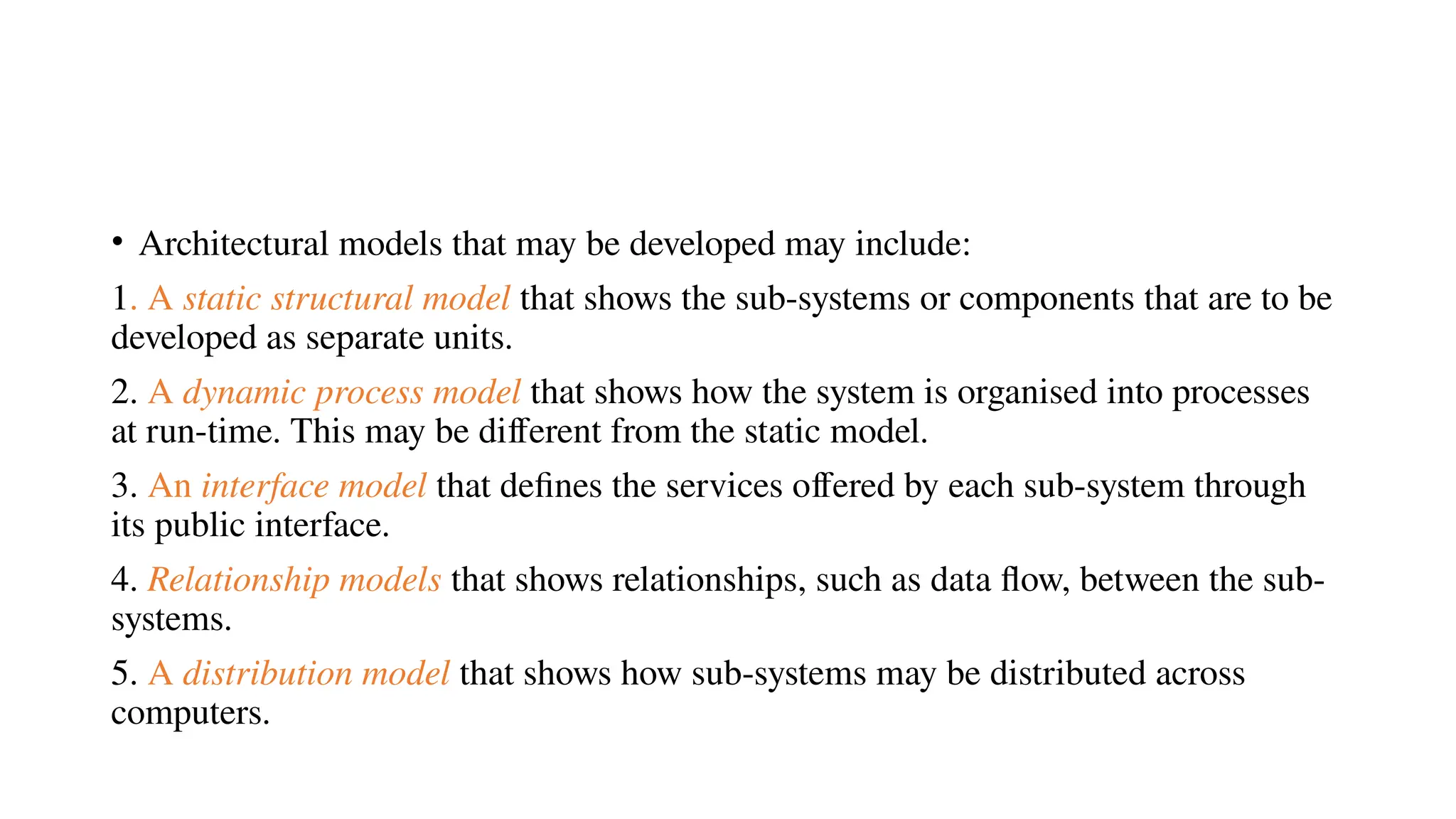
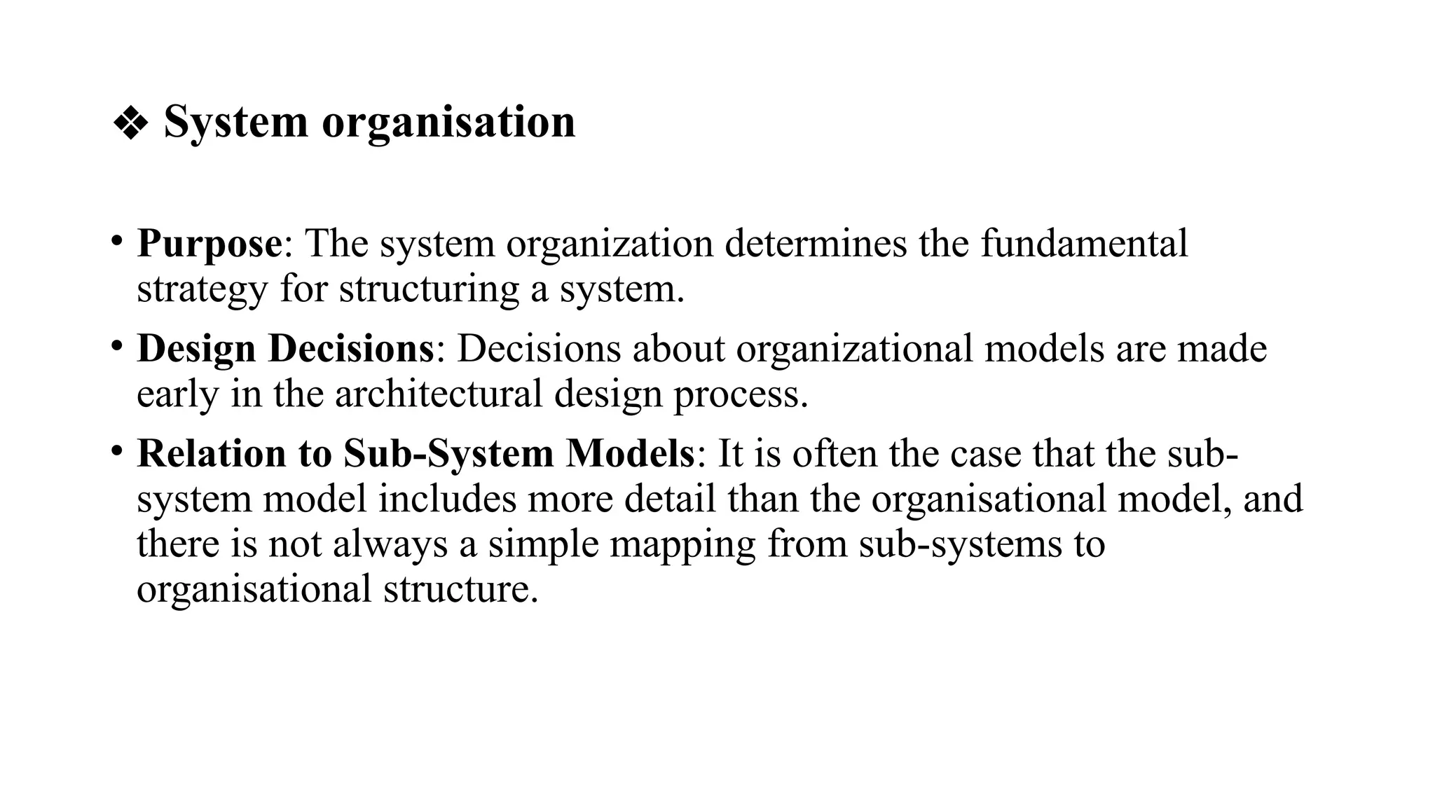
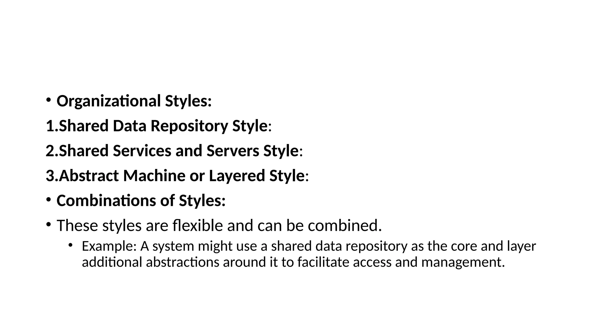
b) Architectural Design:
• Architectural design decisions;
• System organization;
• Modular decomposition styles;
• Control styles,
• reference architectures .
Architectural design
• Large systems are always decomposed into sub-systems that
provide some related set of services.
• The initial design process of identifying these sub-systems
and establishing a framework for sub-system control and
communication is called architectural design.
• The output of this design process is a description of the
software architecture.
•Architectural design is the first stage in the design
process and represents a critical link between the
design and requirements engineering processes.
•The architectural design process is concerned with
establishing a basic structural framework that identifies
the major components of a system and the
communications between these components.
Three advantages of designing and documenting a software architecture:
1. Stakeholder communication The architecture is a high-level presentation of the
system that may be used as a focus for discussion by a range of different
stakeholders.
2. System analysis Making the system architecture explicit at an early stage in the
system development requires some analysis. Architectural design decisions have a
profound effect on whether the system can meet critical requirements such as
performance, reliability and maintainability.
3. Large-scale reuse A system architecture model is a compact, manageable
description of how a system is organised and how the components interoperate. The
system architecture is often the same for systems with similar requirements and so
can support large-scale software reuse.
• The particular style and structure chosen for an application may
therefore depend on the non-functional system requirements:
1. Performance For systems with critical performance requirements,
the architecture should centralize key operations within a few
subsystems, minimizing inter-subsystem communication.
2. Security For systems with critical security requirements, a layered
architecture should protect the most critical assets in the innermost
layers with high level security validation.
3. Safety For systems with critical safety requirements, the architecture
should centralize safety-related operations within a single subsystem or
a small number of subsystems to simplify safety validation and enable
related protection systems.
4. Availability For systems with critical availability requirements, the
architecture should include redundant components and support
component replacement or updates without halting the system,
ensuring fault tolerance.
5. Maintainability For systems with critical maintainability
requirements, the architecture should use self-contained components,
separate data from consumers, and avoid shared data structures.
• Figure 11.1 is an abstract model of the architecture for a packing robot
system that shows The packing robot system that consists of
subsystems for vision, object identification, packaging selection, and
object movement.
• It identifies objects on a delivery conveyor, selects appropriate
packaging, and places the packaged objects on a separate conveyor.
• Simple box-and-line diagrams have limitations because they do not
show detailed relationships between system components or their
external properties. However, they help identify key subsystems for
independent development, allowing managers to assign tasks. These
diagrams should not be the only model used but are one of several
useful architectural tools.
• Breaking a system into subsystems is challenging and depends heavily
on system requirements. The goal is to design subsystems that closely
match requirements so that changes affect only specific parts, not the
entire system.
❖ Architectural design decisions
• Architectural design is a creative process aimed at organizing a system to meet its
functional and non-functional requirements. The process varies greatly depending on the
type of system, the architect's experience, and the system's specific needs. Instead of
focusing on activities, it is more useful to view architectural design as a series of
decisions.
• Key decisions include:
1.Can a generic application architecture serve as a template?
2.How will the system be distributed across processors?
3.What architectural style(s) are suitable?
4.What fundamental structure will the system follow?
5.How will structural units be divided into modules?
6.What strategy will control the operation of system units?
7.How will the design be evaluated?
8.How will the system architecture be documented?
• When designing a system architecture, you have to decide what your system and
broader application classes have in common, and decide how much knowledge
from these application architectures you can reuse.
• The architectural design process produces an architectural design document.
This document includes graphical representations of the system and descriptive
text. It explains how the system is divided into subsystems, the design approach
used, and how each subsystem is broken into modules. The graphical models
provide different views or perspectives on the system architecture.
• Architectural models that may be developed may include:
1. A static structural model that shows the sub-systems or components that are to be
developed as separate units.
2. A dynamic process model that shows how the system is organised into processes
at run-time. This may be different from the static model.
3. An interface model that defines the services offered by each sub-system through
its public interface.
4. Relationship models that shows relationships, such as data flow, between the sub-
systems.
5. A distribution model that shows how sub-systems may be distributed across
computers.
• A number of researchers have proposed the use of architectural
description languages (ADLs) to describe system architectures. The
basic elements of ADLs are components and connectors, and they
include rules and guidelines for well-formed architectures.
❖ System organisation
• Purpose: The system organization determines the fundamental
strategy for structuring a system.
• Design Decisions: Decisions about organizational models are made
early in the architectural design process.
• Relation to Sub-System Models: It is often the case that the sub-
system model includes more detail than the organisational model, and
there is not always a simple mapping from sub-systems to
organisational structure.
• Organizational Styles:
1.Shared Data Repository Style:
2.Shared Services and Servers Style:
3.Abstract Machine or Layered Style:
• Combinations of Styles:
• These styles are flexible and can be combined.
• Example: A system might use a shared data repository as the core and layer
additional abstractions around it to facilitate access and management.
Shared Data Repository Style:
• Sub-systems making up a system must exchange information so that
they can work together effectively. There are two fundamental ways in
which this can be done.
1. All shared data is held in a central database that can be accessed by all
subsystems. A system model based on a shared database is sometimes
called a repository model.
2. Each sub-system maintains its own database. Data is interchanged
with other sub-systems by passing messages to them.
• The majority of systems that use large amounts of data are
organised around a shared database or repository.
• This model is therefore suited to applications where data is
generated by one sub-system and used by another.
• Examples of this type of system include command and
control systems, management information systems, CAD
systems and CASE toolsets.
• Figure 11.2 is an example of a CASE toolset architecture
based on a shared repository.
The advantages and disadvantages of a shared
repository are as follows:
Advantages
1. It is an efficient way to share
large amounts of data. There is
no need to transmit data
explicitly from one sub-system
to another.
2. Sub-systems that produce data
need not be concerned with
how that data is used by other
sub-systems.
Disadvantages
1. However Sub-systems must
compromise on a shared repository
data model, which can affect
performance and hinder integration of
new sub-systems if their models are
incompatible.
2. However, Evolving the system is
difficult and costly due to the large
volume of data tied to the agreed
model, making translation to a new
model expensive or even impossible.
3. Centralized activities like
backup, security, access control,
and error recovery are managed
by the repository, allowing tools
to focus on their main functions.
4. The repository model enables
straightforward integration of
new tools if they are compatible
with the agreed data model.
3. However, different sub-systems
may have different requirements
for security, recovery and backup
policies. The repository model
forces the same policy on all sub-
systems.
4. However, Distributing a logically
centralized repository across
machines can cause issues with
data redundancy and inconsistency.
The client–server model
•The client–server architectural model is a system
model where the system is organised as a set of
services and associated servers and clients that access
and use the services.
The major components of this model are:
1. A set of servers that offer services to other sub-systems. Examples of
servers are print servers that offer printing services, file servers that
offer file management services and a compile server, which offers
programming language compilation services.
2. Clients, typically sub-systems, call on services provided by servers,
with multiple instances of a client program potentially running
concurrently.
3. A network enables clients to access services, though client-server
systems often run as distributed systems rather than on a single
machine.
• Clients must know server names and services, but servers need not
know client identities or numbers; clients use remote procedure calls
with a request-reply protocol like HTTP to access server services.
• Figure 11.3 shows an example of a system that is based on the client–
server model.
• This is a multi-user, web-based system to provide a film and
photograph library.
• From figure, Several servers manage
and display different types of media.
• Video frames need to be
transmitted quickly and in
synchrony but at low resolution.
• The video server handles video
compression and decompression
into various formats.
• Still pictures must be maintained at
high resolution, so they are stored
on a separate server.
• The catalogue manages queries
and provides links to web
information systems.
• These systems include data
about films, video clips, and an
e-commerce system for sales.
• The client program is an
integrated user interface built
using a web browser to access
these services.
• The main advantage of the client-server model is its distributed
architecture, allowing efficient use of networked systems with
multiple processors. It is easy to add or upgrade servers without
impacting other parts of the system.
• However Changes to existing clients and servers may be needed to
fully integrate a new server, as there may be no shared data model,
and servers may organize data differently. Although XML-based data
representation can simplify schema conversion, it is inefficient,
potentially causing performance issues.(XML-Extensible Markup
Language used to define and store data in a sharable manner )
The layered model
• The layered architecture organizes a system into layers, each
providing a set of services.
• Each layer acts as an abstract machine, with its "machine language"
defined by the services it offers.
• This language is used to implement the next layer.
• For example, a language can be implemented by defining an ideal
"language machine," compiling the language into code for it, and then
translating this abstract machine code into real machine code.
Figure 11.4 reflects the APSE structure and shows how a configuration
management system might be integrated using this abstract machine
approach.
• The configuration management
system relies on an object
management system for storing
and managing configuration items
or objects.
• Built on top of a database, it
provides data storage services
such as transaction management,
rollback, recovery, and access
control, utilizing the operating
system's facilities and filestore for
implementation.
advantages
• The layered approach supports incremental system development,
where services from each layer can be made available as it's
developed.
• This architecture is changeable and portable, as long as the interface
remains unchanged, allowing one layer to be replaced with another.
• Changes to layer interfaces or the addition of new features only affect
the adjacent layer.
• By localizing machine dependencies in the inner layers, it simplifies
multi-platform implementation.
Modular decomposition styles
• When designing a system, after selecting the overall system organization, the
next step is to break the system into smaller, manageable components using
modular decomposition.
• Although there is no strict boundary between system organization and modular
decomposition, the following distinctions help guide the design process:
• A sub-system is essentially a self-contained, independent system within the larger system.
• Its functionality does not rely directly on services from other sub-systems, making it relatively
autonomous.
• Sub-systems are usually composed of smaller modules and expose well-defined interfaces to interact
with other sub-systems.
• Sub-systems can sometimes be reused across different systems due to their independence and clear
boundaries.
•A module is a smaller, dependent component that implements specific functionalities or provides
services.
•Unlike sub-systems, modules typically rely on other modules to perform their tasks and are not
considered standalone entities.
•Modules may be built from simpler components and are designed with the purpose of fulfilling specific
roles within the larger sub-system or system.
• There are two main strategies that you can use when decomposing a sub-system
into modules:
1. Object-oriented decomposition where you decompose a system into a set of
communicating objects.
2. Function-oriented pipelining where you decompose a system into functional
modules that accept input data and transform it into output data.
Object-oriented decomposition
• In the object-oriented approach, modules are objects with private state and defined
operations on that state.
• An object-oriented, architectural model structures the system into a set of loosely
coupled objects with well-defined interfaces. Objects call on the services offered
by other objects.
• Figure 11.5 is an example of an object-oriented architectural model of an invoice
processing system.
• This system can issue invoices to customers, receive payments, and issue receipts
for these payments and reminders for unpaid invoices.
• the UML notation is used , where object classes have names and a set of associated
attributes. Operations, if any, are defined in the lower part of the rectangle
representing the object. Dashed arrows indicate that an object uses the attributes or
services provided by another object.
• From fig Object-oriented decomposition focuses on defining object
classes, their attributes, and operations, with objects instantiated from
these classes and coordinated by a control model.
• For example, an Invoice class with operations implementing system
functionality interacts with related classes like Customer, Payment,
and Receipt.
Advantages
• The object-oriented approach enables modular, reusable system design
for real-world entity representations, supported by programming
languages that directly implement architectural components.
Disadvantages:
• The object-oriented approach has drawbacks, such as dependency on
explicit references to object names and interfaces, challenges in
managing interface changes, and difficulty representing complex real-
world entities as objects.
Function-oriented pipelining
• In a function-oriented pipeline or data-flow model, data flows
sequentially or in parallel through a series of functional transformations,
where each step processes inputs to produce outputs. These
transformations handle data either item by item or in batches, converting
it into the desired output.
• When transformations are implemented as separate processes, this
model is often called the pipe and filter style.
• Variants of the pipelining model have been used since the early days of
automatic data processing. When transformations occur sequentially and
process data in batches, the model is referred to as a batch sequential
model.
• An example of this type of system architecture is shown in Figure 11.6.
which is a weekly invoicing system
• where customer payments are responded with issued invoices.
• Paid invoices generate receipts, while overdue invoices trigger
reminders.
Figure 11.6 A pipeline model of an invoice processing system
The advantages of this architecture are:
1. It supports the reuse of transformations.
2. Many people think of their work in terms of input and output
processing.
3. Evolving the system by adding new transformations is usually
straightforward.
4. It is simple to implement either as a concurrent or a sequential
system.
Disadvantages
• The main challenge with the pipelining model is ensuring a common
data format for communication between transformations, which
increases overhead and limits compatibility with non-standard
formats.
• Additionally, interactive systems, especially those with graphical user
interfaces and event-driven controls, are difficult to implement due to
the model's reliance on a continuous data stream.
❖Control styles
• Structural models focus on decomposing a system into sub-systems
but do not include control details, which are handled separately by a
control model.
• Control models define the flow of control between sub-systems to
ensure their services are delivered correctly and on time.
• There are two generic control styles that are used in software systems:
1. Centralised control One sub-system has overall responsibility for
control and starts and stops other sub-systems. It may also devolvep
control to another subsystem but will expect to have this control
responsibility returned to it.
2. Event-based control Rather than control information being embedded
in a subsystem, each sub-system can respond to externally generated
events. These events might come from other sub-systems or from the
environment of the system.
Centralised control
• In a centralised control model, one sub-system is designated as the
system controller and has responsibility for managing the execution of
other sub-systems. Centralised control models fall into two classes,
depending on whether the controlled sub-systems execute sequentially
or in parallel.
1. The call–return model .
2. The manager model.
1. The call–return model : This is the familiar top-down subroutine model where
control starts at the top of a subroutine hierarchy and, through subroutine calls,
passes to lower levels in the tree. The subroutine model is only applicable to
sequential systems.
The call-return model represents program dynamics where control passes from
higher-level routines to lower-level routines and returns to the calling point,
ensuring clear control flow. While its rigid structure simplifies analysis of control
flows, it also makes handling exceptions to normal operations more challenging. As
shown in figure below
The call–return model is illustrated in Figure 11.7.
2. The manager model The manager model applies to both concurrent
and sequential systems, where one component acts as the manager to
control starting, stopping, and coordinating other processes or
subsystems. In concurrent systems, processes run in parallel, while in
sequential systems, the manager calls specific subsystems based on state
variables, typically implemented using a case statement.
• The centralized management model of control is commonly used in
soft real-time systems, where a central controller manages the
execution of processes based on system state variables. Often
referred to as the event-loop model, the controller continuously polls
sensors and processes for events or state changes to decide when to
start, stop, or exchange information between processes.
2. Event-based control
• Event-driven control models respond to externally generated events,
which can range from binary signals to more complex inputs, such as
menu commands or changes in attribute values. The key distinction is
that the timing of the event is not controlled by the process handling
it, and these models are used in systems like editors, rule-based
production systems in AI, and active objects, where changes in
conditions or attributes trigger actions.
• two event-driven control models:
1. Broadcast models.
2. Interrupt-driven models
1. Broadcast models In these models, an event is broadcast to all sub-systems.
Any sub-system that has been programmed to handle that event can respond to it.
• Broadcast models are effective in integrating sub-systems distributed across
different computers on a network.
• In the broadcast model, sub-systems register their interest in specific events, and
when those events occur, control is transferred to the appropriate sub-system to
handle them.
• The broadcast model allows sub-systems to independently decide which events
they need, with the event handler ensuring that these events are routed to the
correct sub-systems.
Advantage
• The broadcast approach offers the advantage of simplicity in
evolution, as new sub-systems can be easily integrated by registering
their events with the event handler. This model allows sub-systems to
interact with each other without needing to know the names or
locations of other sub-systems, and it supports distribution across
multiple machines, with this distribution being transparent to other
sub-systems.
Disadvantage
• The disadvantage of the broadcast model is that sub-systems cannot
predict if or when events will be handled. When a sub-system
generates an event, it does not know which other sub-systems are
interested in it, and multiple sub-systems may register for the same
event, potentially leading to conflicts when the results of event
handling are made available.
2. Interrupt-driven models These are exclusively used in real-time
systems where external interrupts are detected by an interrupt handler.
They are then passed to some other component for processing.
• Interrupt-driven models are used in real-time systems with
stringent timing requirements.
• Real-time systems that need to handle events quickly, such as safety
systems in cars, must be event-driven to ensure timely responses. For
example, detecting a crash and inflating an airbag before the driver's
head hits the steering wheel requires interrupt-driven control, which
allows immediate action in response to critical events.
An interrupt-driven control model is illustrated in Figure 11.10
From figure
• There are a known number of interrupt types with a handler defined for each type.
• Each type of interrupt is associated with the memory location where its handler’s
address is stored.
• When an interrupt of a particular type is received, a hardware switch causes
control to be transferred immediately to its handler.
• This interrupt handler may then start or stop other processes in response to the
event signalled by the interrupt.
• This model is mostly used in real-time systems where an immediate response to
some event is necessary. It may be combined with the centralised management
model.
• The central manager handles the normal running of the system with interrupt-
based control for emergencies.
• Advantages of Interrupt-Driven Control:
• Provides very fast responses to events, enabling timely actions in real-
time systems (e.g., airbag inflation before a crash).
• Allows for immediate processing of critical events, ensuring that time-
sensitive tasks are handled efficiently.
• Disadvantages of Interrupt-Driven Control:
• Complex to program and difficult to validate, as precise control over
timing and event handling is required.
• It may be impossible to replicate interrupt timing patterns during
system testing, making it harder to ensure system reliability.
• If the hardware limits the number of interrupts, adding more events
becomes difficult, and no other events can be processed once the
limit is reached.
❖Reference architectures
• The architectural models are general models: They can be applied to
many classes of application.
• Architectural models that are specific to a particular application
domain may also be used.
• Although these systems differ in detail, the common architectural
structure can be reused when developing new systems.
• These architectural models are called domain specific architectures.
There are two types of domain-specific architectural model:
1. Generic models
2. Reference models
Generic models:
• Generic models are abstractions derived from multiple real systems,
capturing the key characteristics shared across these systems.
• For example, in real-time systems, generic architectural models may
exist for different system types, such as data collection systems or
monitoring systems, providing a reusable framework for similar
applications.
Reference models:
• Reference models are more abstract and describe a larger class of
systems.
• They are a way of informing designers about the general structure of
that class of system. Reference models are usually derived from a study
of the application domain.
• They represent an idealised architecture that includes all the features
that systems might incorporate.
• Reference models are normally used to communicate domain concepts
and compare or evaluate possible architectures.
Purpose of a Reference Model
• Provides guidelines for system design and development.
• Ensures consistency across projects or teams.
• Enables reusability of concepts and solutions.
• Helps analyze and compare systems.
The CASE reference model is illustrated in Figure 11.12.
The five levels of service in the CASE reference model are:
1. Data repository services These provide facilities for
the storage and management of data items and their
relationships.
2. Data integration services These provide facilities for
managing groups or the establishment of relationships
between them. These services and data repository
services are the basis of data integration in the
environment.
3. Task management services These provide facilities
for the definition and enactment of process models.
They support process integration.
4. Message services These provide facilities for tool-
tool, environment-tool and environment-environment
communications. They support control integration.
5. User interface services These provide facilities for
user interface development. They support presentation
integration.
summary
A reference model for a CASE (Computer-Aided Software
Engineering) environment outlines the potential features that
might be included in any specific system, though not all of them
will necessarily appear in every design. It allows designers to ask
critical questions,
such as "How are the data repository services provided?" and
"Does the system provide task management?“ to evaluate whether
the system meets the necessary requirements.
Thank you

VTU_SE_Module-4_b) Architectural Design.pptx

  • 1.
    b) Architectural Design: •Architectural design decisions; • System organization; • Modular decomposition styles; • Control styles, • reference architectures .
  • 2.
    Architectural design • Largesystems are always decomposed into sub-systems that provide some related set of services. • The initial design process of identifying these sub-systems and establishing a framework for sub-system control and communication is called architectural design. • The output of this design process is a description of the software architecture.
  • 3.
    •Architectural design isthe first stage in the design process and represents a critical link between the design and requirements engineering processes. •The architectural design process is concerned with establishing a basic structural framework that identifies the major components of a system and the communications between these components.
  • 4.
    Three advantages ofdesigning and documenting a software architecture: 1. Stakeholder communication The architecture is a high-level presentation of the system that may be used as a focus for discussion by a range of different stakeholders. 2. System analysis Making the system architecture explicit at an early stage in the system development requires some analysis. Architectural design decisions have a profound effect on whether the system can meet critical requirements such as performance, reliability and maintainability. 3. Large-scale reuse A system architecture model is a compact, manageable description of how a system is organised and how the components interoperate. The system architecture is often the same for systems with similar requirements and so can support large-scale software reuse.
  • 5.
    • The particularstyle and structure chosen for an application may therefore depend on the non-functional system requirements: 1. Performance For systems with critical performance requirements, the architecture should centralize key operations within a few subsystems, minimizing inter-subsystem communication.
  • 6.
    2. Security Forsystems with critical security requirements, a layered architecture should protect the most critical assets in the innermost layers with high level security validation. 3. Safety For systems with critical safety requirements, the architecture should centralize safety-related operations within a single subsystem or a small number of subsystems to simplify safety validation and enable related protection systems.
  • 7.
    4. Availability Forsystems with critical availability requirements, the architecture should include redundant components and support component replacement or updates without halting the system, ensuring fault tolerance. 5. Maintainability For systems with critical maintainability requirements, the architecture should use self-contained components, separate data from consumers, and avoid shared data structures.
  • 8.
    • Figure 11.1is an abstract model of the architecture for a packing robot system that shows The packing robot system that consists of subsystems for vision, object identification, packaging selection, and object movement. • It identifies objects on a delivery conveyor, selects appropriate packaging, and places the packaged objects on a separate conveyor.
  • 10.
    • Simple box-and-linediagrams have limitations because they do not show detailed relationships between system components or their external properties. However, they help identify key subsystems for independent development, allowing managers to assign tasks. These diagrams should not be the only model used but are one of several useful architectural tools. • Breaking a system into subsystems is challenging and depends heavily on system requirements. The goal is to design subsystems that closely match requirements so that changes affect only specific parts, not the entire system.
  • 11.
    ❖ Architectural designdecisions • Architectural design is a creative process aimed at organizing a system to meet its functional and non-functional requirements. The process varies greatly depending on the type of system, the architect's experience, and the system's specific needs. Instead of focusing on activities, it is more useful to view architectural design as a series of decisions. • Key decisions include: 1.Can a generic application architecture serve as a template? 2.How will the system be distributed across processors? 3.What architectural style(s) are suitable? 4.What fundamental structure will the system follow? 5.How will structural units be divided into modules? 6.What strategy will control the operation of system units? 7.How will the design be evaluated? 8.How will the system architecture be documented?
  • 12.
    • When designinga system architecture, you have to decide what your system and broader application classes have in common, and decide how much knowledge from these application architectures you can reuse. • The architectural design process produces an architectural design document. This document includes graphical representations of the system and descriptive text. It explains how the system is divided into subsystems, the design approach used, and how each subsystem is broken into modules. The graphical models provide different views or perspectives on the system architecture.
  • 13.
    • Architectural modelsthat may be developed may include: 1. A static structural model that shows the sub-systems or components that are to be developed as separate units. 2. A dynamic process model that shows how the system is organised into processes at run-time. This may be different from the static model. 3. An interface model that defines the services offered by each sub-system through its public interface. 4. Relationship models that shows relationships, such as data flow, between the sub- systems. 5. A distribution model that shows how sub-systems may be distributed across computers.
  • 14.
    • A numberof researchers have proposed the use of architectural description languages (ADLs) to describe system architectures. The basic elements of ADLs are components and connectors, and they include rules and guidelines for well-formed architectures.
  • 15.
    ❖ System organisation •Purpose: The system organization determines the fundamental strategy for structuring a system. • Design Decisions: Decisions about organizational models are made early in the architectural design process. • Relation to Sub-System Models: It is often the case that the sub- system model includes more detail than the organisational model, and there is not always a simple mapping from sub-systems to organisational structure.
  • 16.
    • Organizational Styles: 1.SharedData Repository Style: 2.Shared Services and Servers Style: 3.Abstract Machine or Layered Style: • Combinations of Styles: • These styles are flexible and can be combined. • Example: A system might use a shared data repository as the core and layer additional abstractions around it to facilitate access and management.
  • 17.
    Shared Data RepositoryStyle: • Sub-systems making up a system must exchange information so that they can work together effectively. There are two fundamental ways in which this can be done. 1. All shared data is held in a central database that can be accessed by all subsystems. A system model based on a shared database is sometimes called a repository model. 2. Each sub-system maintains its own database. Data is interchanged with other sub-systems by passing messages to them.
  • 18.
    • The majorityof systems that use large amounts of data are organised around a shared database or repository. • This model is therefore suited to applications where data is generated by one sub-system and used by another. • Examples of this type of system include command and control systems, management information systems, CAD systems and CASE toolsets. • Figure 11.2 is an example of a CASE toolset architecture based on a shared repository.
  • 20.
    The advantages anddisadvantages of a shared repository are as follows: Advantages 1. It is an efficient way to share large amounts of data. There is no need to transmit data explicitly from one sub-system to another. 2. Sub-systems that produce data need not be concerned with how that data is used by other sub-systems. Disadvantages 1. However Sub-systems must compromise on a shared repository data model, which can affect performance and hinder integration of new sub-systems if their models are incompatible. 2. However, Evolving the system is difficult and costly due to the large volume of data tied to the agreed model, making translation to a new model expensive or even impossible.
  • 21.
    3. Centralized activitieslike backup, security, access control, and error recovery are managed by the repository, allowing tools to focus on their main functions. 4. The repository model enables straightforward integration of new tools if they are compatible with the agreed data model. 3. However, different sub-systems may have different requirements for security, recovery and backup policies. The repository model forces the same policy on all sub- systems. 4. However, Distributing a logically centralized repository across machines can cause issues with data redundancy and inconsistency.
  • 22.
    The client–server model •Theclient–server architectural model is a system model where the system is organised as a set of services and associated servers and clients that access and use the services.
  • 23.
    The major componentsof this model are: 1. A set of servers that offer services to other sub-systems. Examples of servers are print servers that offer printing services, file servers that offer file management services and a compile server, which offers programming language compilation services. 2. Clients, typically sub-systems, call on services provided by servers, with multiple instances of a client program potentially running concurrently. 3. A network enables clients to access services, though client-server systems often run as distributed systems rather than on a single machine.
  • 24.
    • Clients mustknow server names and services, but servers need not know client identities or numbers; clients use remote procedure calls with a request-reply protocol like HTTP to access server services. • Figure 11.3 shows an example of a system that is based on the client– server model. • This is a multi-user, web-based system to provide a film and photograph library.
  • 26.
    • From figure,Several servers manage and display different types of media. • Video frames need to be transmitted quickly and in synchrony but at low resolution. • The video server handles video compression and decompression into various formats. • Still pictures must be maintained at high resolution, so they are stored on a separate server.
  • 27.
    • The cataloguemanages queries and provides links to web information systems. • These systems include data about films, video clips, and an e-commerce system for sales. • The client program is an integrated user interface built using a web browser to access these services.
  • 28.
    • The mainadvantage of the client-server model is its distributed architecture, allowing efficient use of networked systems with multiple processors. It is easy to add or upgrade servers without impacting other parts of the system. • However Changes to existing clients and servers may be needed to fully integrate a new server, as there may be no shared data model, and servers may organize data differently. Although XML-based data representation can simplify schema conversion, it is inefficient, potentially causing performance issues.(XML-Extensible Markup Language used to define and store data in a sharable manner )
  • 29.
    The layered model •The layered architecture organizes a system into layers, each providing a set of services. • Each layer acts as an abstract machine, with its "machine language" defined by the services it offers. • This language is used to implement the next layer. • For example, a language can be implemented by defining an ideal "language machine," compiling the language into code for it, and then translating this abstract machine code into real machine code.
  • 30.
    Figure 11.4 reflectsthe APSE structure and shows how a configuration management system might be integrated using this abstract machine approach. • The configuration management system relies on an object management system for storing and managing configuration items or objects. • Built on top of a database, it provides data storage services such as transaction management, rollback, recovery, and access control, utilizing the operating system's facilities and filestore for implementation.
  • 31.
    advantages • The layeredapproach supports incremental system development, where services from each layer can be made available as it's developed. • This architecture is changeable and portable, as long as the interface remains unchanged, allowing one layer to be replaced with another. • Changes to layer interfaces or the addition of new features only affect the adjacent layer. • By localizing machine dependencies in the inner layers, it simplifies multi-platform implementation.
  • 32.
    Modular decomposition styles •When designing a system, after selecting the overall system organization, the next step is to break the system into smaller, manageable components using modular decomposition. • Although there is no strict boundary between system organization and modular decomposition, the following distinctions help guide the design process:
  • 33.
    • A sub-systemis essentially a self-contained, independent system within the larger system. • Its functionality does not rely directly on services from other sub-systems, making it relatively autonomous. • Sub-systems are usually composed of smaller modules and expose well-defined interfaces to interact with other sub-systems. • Sub-systems can sometimes be reused across different systems due to their independence and clear boundaries. •A module is a smaller, dependent component that implements specific functionalities or provides services. •Unlike sub-systems, modules typically rely on other modules to perform their tasks and are not considered standalone entities. •Modules may be built from simpler components and are designed with the purpose of fulfilling specific roles within the larger sub-system or system.
  • 34.
    • There aretwo main strategies that you can use when decomposing a sub-system into modules: 1. Object-oriented decomposition where you decompose a system into a set of communicating objects. 2. Function-oriented pipelining where you decompose a system into functional modules that accept input data and transform it into output data.
  • 35.
    Object-oriented decomposition • Inthe object-oriented approach, modules are objects with private state and defined operations on that state. • An object-oriented, architectural model structures the system into a set of loosely coupled objects with well-defined interfaces. Objects call on the services offered by other objects. • Figure 11.5 is an example of an object-oriented architectural model of an invoice processing system. • This system can issue invoices to customers, receive payments, and issue receipts for these payments and reminders for unpaid invoices. • the UML notation is used , where object classes have names and a set of associated attributes. Operations, if any, are defined in the lower part of the rectangle representing the object. Dashed arrows indicate that an object uses the attributes or services provided by another object.
  • 37.
    • From figObject-oriented decomposition focuses on defining object classes, their attributes, and operations, with objects instantiated from these classes and coordinated by a control model. • For example, an Invoice class with operations implementing system functionality interacts with related classes like Customer, Payment, and Receipt.
  • 38.
    Advantages • The object-orientedapproach enables modular, reusable system design for real-world entity representations, supported by programming languages that directly implement architectural components. Disadvantages: • The object-oriented approach has drawbacks, such as dependency on explicit references to object names and interfaces, challenges in managing interface changes, and difficulty representing complex real- world entities as objects.
  • 39.
    Function-oriented pipelining • Ina function-oriented pipeline or data-flow model, data flows sequentially or in parallel through a series of functional transformations, where each step processes inputs to produce outputs. These transformations handle data either item by item or in batches, converting it into the desired output. • When transformations are implemented as separate processes, this model is often called the pipe and filter style. • Variants of the pipelining model have been used since the early days of automatic data processing. When transformations occur sequentially and process data in batches, the model is referred to as a batch sequential model.
  • 40.
    • An exampleof this type of system architecture is shown in Figure 11.6. which is a weekly invoicing system • where customer payments are responded with issued invoices. • Paid invoices generate receipts, while overdue invoices trigger reminders.
  • 41.
    Figure 11.6 Apipeline model of an invoice processing system
  • 42.
    The advantages ofthis architecture are: 1. It supports the reuse of transformations. 2. Many people think of their work in terms of input and output processing. 3. Evolving the system by adding new transformations is usually straightforward. 4. It is simple to implement either as a concurrent or a sequential system.
  • 43.
    Disadvantages • The mainchallenge with the pipelining model is ensuring a common data format for communication between transformations, which increases overhead and limits compatibility with non-standard formats. • Additionally, interactive systems, especially those with graphical user interfaces and event-driven controls, are difficult to implement due to the model's reliance on a continuous data stream.
  • 44.
    ❖Control styles • Structuralmodels focus on decomposing a system into sub-systems but do not include control details, which are handled separately by a control model. • Control models define the flow of control between sub-systems to ensure their services are delivered correctly and on time.
  • 45.
    • There aretwo generic control styles that are used in software systems: 1. Centralised control One sub-system has overall responsibility for control and starts and stops other sub-systems. It may also devolvep control to another subsystem but will expect to have this control responsibility returned to it. 2. Event-based control Rather than control information being embedded in a subsystem, each sub-system can respond to externally generated events. These events might come from other sub-systems or from the environment of the system.
  • 46.
    Centralised control • Ina centralised control model, one sub-system is designated as the system controller and has responsibility for managing the execution of other sub-systems. Centralised control models fall into two classes, depending on whether the controlled sub-systems execute sequentially or in parallel. 1. The call–return model . 2. The manager model.
  • 47.
    1. The call–returnmodel : This is the familiar top-down subroutine model where control starts at the top of a subroutine hierarchy and, through subroutine calls, passes to lower levels in the tree. The subroutine model is only applicable to sequential systems. The call-return model represents program dynamics where control passes from higher-level routines to lower-level routines and returns to the calling point, ensuring clear control flow. While its rigid structure simplifies analysis of control flows, it also makes handling exceptions to normal operations more challenging. As shown in figure below
  • 48.
    The call–return modelis illustrated in Figure 11.7.
  • 49.
    2. The managermodel The manager model applies to both concurrent and sequential systems, where one component acts as the manager to control starting, stopping, and coordinating other processes or subsystems. In concurrent systems, processes run in parallel, while in sequential systems, the manager calls specific subsystems based on state variables, typically implemented using a case statement.
  • 50.
    • The centralizedmanagement model of control is commonly used in soft real-time systems, where a central controller manages the execution of processes based on system state variables. Often referred to as the event-loop model, the controller continuously polls sensors and processes for events or state changes to decide when to start, stop, or exchange information between processes.
  • 52.
    2. Event-based control •Event-driven control models respond to externally generated events, which can range from binary signals to more complex inputs, such as menu commands or changes in attribute values. The key distinction is that the timing of the event is not controlled by the process handling it, and these models are used in systems like editors, rule-based production systems in AI, and active objects, where changes in conditions or attributes trigger actions. • two event-driven control models: 1. Broadcast models. 2. Interrupt-driven models
  • 53.
    1. Broadcast modelsIn these models, an event is broadcast to all sub-systems. Any sub-system that has been programmed to handle that event can respond to it. • Broadcast models are effective in integrating sub-systems distributed across different computers on a network. • In the broadcast model, sub-systems register their interest in specific events, and when those events occur, control is transferred to the appropriate sub-system to handle them. • The broadcast model allows sub-systems to independently decide which events they need, with the event handler ensuring that these events are routed to the correct sub-systems.
  • 55.
    Advantage • The broadcastapproach offers the advantage of simplicity in evolution, as new sub-systems can be easily integrated by registering their events with the event handler. This model allows sub-systems to interact with each other without needing to know the names or locations of other sub-systems, and it supports distribution across multiple machines, with this distribution being transparent to other sub-systems.
  • 56.
    Disadvantage • The disadvantageof the broadcast model is that sub-systems cannot predict if or when events will be handled. When a sub-system generates an event, it does not know which other sub-systems are interested in it, and multiple sub-systems may register for the same event, potentially leading to conflicts when the results of event handling are made available.
  • 57.
    2. Interrupt-driven modelsThese are exclusively used in real-time systems where external interrupts are detected by an interrupt handler. They are then passed to some other component for processing. • Interrupt-driven models are used in real-time systems with stringent timing requirements.
  • 58.
    • Real-time systemsthat need to handle events quickly, such as safety systems in cars, must be event-driven to ensure timely responses. For example, detecting a crash and inflating an airbag before the driver's head hits the steering wheel requires interrupt-driven control, which allows immediate action in response to critical events.
  • 59.
    An interrupt-driven controlmodel is illustrated in Figure 11.10
  • 60.
    From figure • Thereare a known number of interrupt types with a handler defined for each type. • Each type of interrupt is associated with the memory location where its handler’s address is stored. • When an interrupt of a particular type is received, a hardware switch causes control to be transferred immediately to its handler. • This interrupt handler may then start or stop other processes in response to the event signalled by the interrupt. • This model is mostly used in real-time systems where an immediate response to some event is necessary. It may be combined with the centralised management model. • The central manager handles the normal running of the system with interrupt- based control for emergencies.
  • 61.
    • Advantages ofInterrupt-Driven Control: • Provides very fast responses to events, enabling timely actions in real- time systems (e.g., airbag inflation before a crash). • Allows for immediate processing of critical events, ensuring that time- sensitive tasks are handled efficiently.
  • 62.
    • Disadvantages ofInterrupt-Driven Control: • Complex to program and difficult to validate, as precise control over timing and event handling is required. • It may be impossible to replicate interrupt timing patterns during system testing, making it harder to ensure system reliability. • If the hardware limits the number of interrupts, adding more events becomes difficult, and no other events can be processed once the limit is reached.
  • 63.
    ❖Reference architectures • Thearchitectural models are general models: They can be applied to many classes of application. • Architectural models that are specific to a particular application domain may also be used. • Although these systems differ in detail, the common architectural structure can be reused when developing new systems. • These architectural models are called domain specific architectures.
  • 64.
    There are twotypes of domain-specific architectural model: 1. Generic models 2. Reference models Generic models: • Generic models are abstractions derived from multiple real systems, capturing the key characteristics shared across these systems. • For example, in real-time systems, generic architectural models may exist for different system types, such as data collection systems or monitoring systems, providing a reusable framework for similar applications.
  • 65.
    Reference models: • Referencemodels are more abstract and describe a larger class of systems. • They are a way of informing designers about the general structure of that class of system. Reference models are usually derived from a study of the application domain. • They represent an idealised architecture that includes all the features that systems might incorporate. • Reference models are normally used to communicate domain concepts and compare or evaluate possible architectures.
  • 66.
    Purpose of aReference Model • Provides guidelines for system design and development. • Ensures consistency across projects or teams. • Enables reusability of concepts and solutions. • Helps analyze and compare systems.
  • 67.
    The CASE referencemodel is illustrated in Figure 11.12. The five levels of service in the CASE reference model are: 1. Data repository services These provide facilities for the storage and management of data items and their relationships. 2. Data integration services These provide facilities for managing groups or the establishment of relationships between them. These services and data repository services are the basis of data integration in the environment. 3. Task management services These provide facilities for the definition and enactment of process models. They support process integration. 4. Message services These provide facilities for tool- tool, environment-tool and environment-environment communications. They support control integration. 5. User interface services These provide facilities for user interface development. They support presentation integration.
  • 68.
    summary A reference modelfor a CASE (Computer-Aided Software Engineering) environment outlines the potential features that might be included in any specific system, though not all of them will necessarily appear in every design. It allows designers to ask critical questions, such as "How are the data repository services provided?" and "Does the system provide task management?“ to evaluate whether the system meets the necessary requirements.
  • 69.