1
Module 3
SYSTEMDESIGN
System design-Decomposing the system
Overview of System Design
System design concepts
System Design Activities: Objects to Subsystems
System Design – Addressing design goals:
Activities: An overview of system design activities
UML deployment diagrams
Addressing Design Goals
Managing System Design
2.
S YS TE M D E S I GN I N S O F T W A R E E N GIN E E R I N G R E F E R S T O
T HE PR O C E S S O F P L A N N I N G A N D D E F IN IN G T HE
A R C HI T E C T U R E , C O M PO N E N T S , IN T E R F A C E S , A N D D A T A
FL O W O F A S Y S T E M T O ME E T S PE C IF I C F U N C T I ON A L A N D
N O N - F U N C T I O N A L R E Q U I R E M E N T S . I T I S T HE B L U E PR IN T
OR S T R U C T U R E T HA T G U I D E S T HE D E VE L OP M E N T O F A
S YS T E M .
Module- 3
SYSTEM DESIGN
Steps in SystemDesign
Step 1:Requirement Gathering:
Understand the problem, the requirements, and
constraints of the system.
Collect both functional (what the system should do) and
non-functional (how the system should perform)
requirements.
Step 2:Define the System's High-Level
Components:
Identify the major modules or services that will make up
the system.
Think about how these components will interact with each
other, the data they will handle, and the external systems
they will connect to.
5.
Steps in SystemDesign
Step 3: Design the Data Flow and Interfaces:
Define how data will flow between components,
the type of data, and the interfaces between
components (APIs, databases, etc.).
Step 4: Consider Scaling, Reliability, and
Security:
Plan for future growth, fault tolerance, and
handling system failures.
Think about security and ensure that only
authorized users can access sensitive data and
perform actions.
6.
Steps in SystemDesign
Step 5: Choose Technologies:
Select the tools, programming languages,
frameworks, and databases that will help build
the system.
Step 6: Define Testing Strategies:
Plan how to test the system to ensure that it
meets the requirements and performs well under
load. This includes unit testing, integration
testing, and stress testing.
Step 7: Deployment and Maintenance:
Consider the deployment process, monitoring,
and how the system will be maintained over time.
7.
1. High-Level Design:
UserInterface: For users to view available dates, choose options, and
book.
Booking Service: Manages the booking process.
Payment Service: Handles transactions and integration with third-party
payment systems.
Notification Service: Sends email or SMS notifications to users.
Database: Stores user data, booking details, and transaction history.
2. Low-Level Design:
Booking Service:
Input: Booking request from user interface.
Output: Reservation ID, confirmation message.
Data: Stores booking details (user info, date, time, etc.).
Payment Service:
Input: Payment information from the user.
Output: Payment success/failure status.
Data: Stores payment transactions and confirmation.
Example: Building a System for Online
Booking
8.
1. Decomposition ofthe system
Decomposing a system in system design
refers to breaking down a complex system into
smaller, manageable, and well-structured
components or subsystems.
This helps in reducing complexity,
improving maintainability, enabling
parallel development, and enhancing
scalability.
9.
Decomposition of thesystem
Importance of System Decomposition:
Simplifies System Complexity – Makes the
system easier to understand and develop.
Improves Maintainability – Individual
components can be updated or modified
independently.
Enhances Reusability – Components can be reused
across different projects or systems.
Supports Parallel Development – Different teams
can work on separate modules simultaneously.
Facilitates Scalability – The system can grow by
adding more components without affecting existing
ones.
10.
Approaches to system
decomposition
Thereare several ways to decompose a system
based on different design principles:
A) Functional Decomposition
The system is divided based on its core
functionalities.
Each function or feature is treated as a separate
module.
Example: In a hospital management
system, functional components include Patient
Registration, Billing, Doctor Consultation,
and Pharmacy Management.
11.
Approaches to system
decomposition
B)Object-Oriented Decomposition
The system is decomposed into objects that
encapsulate both data and behavior.
Objects interact with each other through well-
defined interfaces.
Example:
In an online shopping application, objects like User,
Product, Cart, and Order represent different entities.
12.
Approaches to system
decomposition
C)Layered Decomposition
The system is divided into multiple layers where
each layer has a specific responsibility.
Common layers include:
Presentation Layer – Handles user interface and
interaction.
Business Logic Layer – Contains core logic and rules.
Data Layer – Manages database operations.
Example:
A web application with separate frontend (UI),
backend (business logic), and database (storage)
layers.
13.
Approaches to system
decomposition
D)Component-Based Decomposition
The system is broken into reusable components
that operate independently but interact with
each other through APIs.
Often used in Service-Oriented Architecture
(SOA) and Microservices Architecture.
Example:
A food delivery application with independent services
for User Management, Order Processing, Payment
Gateway, and Delivery Tracking.
14.
Approaches to system
decomposition
E)Microservices-BasedDecomposition
The system is divided into small, independent
services that communicate over a network.
Each service is responsible for a single function
and can be deployed separately.
Example:
A social media platform with separate microservices
for User Authentication, Post Management,
Notifications, and Messaging.
15.
Approaches to system
decomposition
F)Database Decomposition
The database is divided into multiple logical or
physical units for better performance and
scalability.
Common techniques include:
Horizontal Partitioning (Sharding) – Splitting data
across multiple databases.
Vertical Partitioning – Storing different attributes in
separate databases.
Example:
A global e-commerce system with separate databases
for customers from different regions (e.g., US,
Europe, Asia).
16.
2. Overview ofSystem Design
System design is the last software engineering
action within the modeling activity and sets the
stage for construction (code generation and
testing).
It is the blueprint or structure that guides the
development of a system.
It is a crucial step in software and hardware
development, ensuring that a system is scalable,
efficient, and maintainable.
17.
Types of SystemDesign
High-Level System Design (Architecture Design): This is
the top-level overview of the system, usually involving the
identification of key components and their interactions. It
provides a rough sketch of the system, showing how
different services, modules, and databases work together.
Examples include monolithic systems, client-server models,
or micro services architectures.
Low-Level System Design: Once the high-level design is
complete, the next step is low-level design, which goes into
more detail about how each component works. This
includes the data structures, algorithms, class diagrams,
database schema, and APIs that make up the individual
components.
18.
Overview of SystemDesign
Fig 1: translating the requirements model
into design model
19.
Overview of SystemDesign
Each of the elements of the requirements model
provides information that is necessary to create
the four design models required for a complete
specification of design. The flow of information
during software design is illustrated in Figure 1.
The requirements model, manifested by
(i)scenario-based elements
(ii)class-based elements
(iii) flow-oriented elements
(iv)and behavioral elements
20.
Overview of SystemDesign
The data/class design model transforms class
models (Chapter 6) into design class real izations
and the requisite data structures required to
implement the software.
The architectural design model defines the
relationship between major structural elements
of the software, the architectural styles and
design patterns and also represents the
framework of a computer-based system.
The interface design model describes how the
software communicates with systems that
interoperate with it, and with humans who use it.
21.
Overview of SystemDesign
The component-level design model
transforms structural elements of the software
architecture into a procedural description of
software components. Information obtained from
the class-based models, flow models, and
behavioral models serve as the basis for
component design.
The importance of software design can be stated
with a single word—quality.
Design provides you with representations of
software that can be assessed for quality.
22.
The Design process
Softwaredesign is an iterative process through
which requirements are translated into a
“blueprint” for constructing the software.
Initially, the blueprint depicts a holistic view of
software. That is, the design is represented at a
high level of abstraction— a level that can be
directly traced to the specific system objective
and more detailed data, functional, and
behavioral requirements.
23.
The Design process
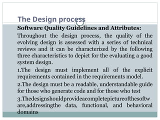
SoftwareQuality Guidelines and Attributes:
Throughout the design process, the quality of the
evolving design is assessed with a series of technical
reviews and it can be characterized by the following
three characteristics to depict for the evaluating a good
system design.
1.The design must implement all of the explicit
requirements contained in the requirements model.
2.The design must be a readable, understandable guide
for those who generate code and for those who test
3.Thedesignshouldprovideacompletepictureofthesoftw
are,addressingthe data, functional, and behavioral
domains
24.
The Design process
QualityGuidelines:
In order to evaluate the quality of a design
representation, consider the following
guidelines:
1.A design should exhibit an architecture that (1) has
been created using recognizable architectural styles
or patterns, (2) exhibit good design characteristics
and (3) can be implemented in an evolutionary
model which depicts implementation and testing.
2. A design should be modular; that is, the software
should be logically partitioned into elements or
subsystems.
25.
The Design process
3.A design should contain distinct representations of data,
architecture, interfaces, and components.
4.A design should lead to data structures that are appropriate
for the classes to be implemented and are drawn from
recognizable data patterns.
5. A design should lead to components that exhibit
independent functional characteristics.
6. A design should lead to interfaces that reduce the
complexity of connections between components and with the
external environment.
7. A design should be derived using a repeatable method that is
driven by information obtained during software requirements
analysis.
8. A design should be represented using a notation that
effectively communicates its meaning.
26.
The Design process
QualityAttributes:
Hewlett-Packard developed a set of software
quality attributes that has been given the
acronym FURPS—functionality, usability,
reliability, performance, and
supportability. The FURPS quality attributes
represent a target for all software design:
1. Functionality: It is assessed by evaluating
the feature set and capabilities of the program.
2. Usability: It is assessed by considering
human factors, overall aesthetics, consistency,
and documentation.
27.
The Design process
3.Reliability: It is evaluated by measuring the
frequency and severity of failure, the accuracy of
output results, the mean-time-to-failure (MTTF),
the ability to recover from failure, and the
predictability of the program.
4.Performance: It is measured by considering
processing speed, response time, resource
consumption, throughput, and efficiency.
5. Supportability: It combines the ability to
extend the program (extensibility), adaptability,
serviceability
28.
3. System DesignConcepts
A set of fundamental software design concepts
has evolved over the history of software
engineering. Each provides the software designer
with a foundation from which more sophisticated
design methods can be applied. Each helps you
answer the following questions:
1.what criteria can be used to partition software
into individual components?
2.How is function or data structure detail separated
from a conceptual representation of the software?
3.What uniform criteria define the technical
quality of a software design?
29.
3. System DesignConcepts
A brief overview of important software design concepts that span both
traditional and object-oriented software development.
1. Abstraction
2. Architecture
3. Patterns
4. Separation of concerns
5. Modularity
6. Information hiding
7. Functional Dependence
8. Refinement
9. Aspects
10. Refactoring
11. Object oriented design concepts
12. Design classes
30.
3. System DesignConcepts
1.Abstraction:
There are two types of abstraction.
1.highest level of abstraction, a solution is
stated in broad terms using the language of the
problem environment.
2.lower levels of abstraction, a more
detailed description of the solution is provided.
As different levels of abstraction are developed,
you work to create both procedural and data
abstractions. A data abstraction is a named
collection of data that describes a data object.
31.
3. System DesignConcepts
2.Architecture:
Software architecture defines “the overall
structure of the software and the ways in
which that structure provides conceptual
integrity for a system.”
Shaw and Garlan describe a set of properties that
should be specified as part of an architectural
design.
1. Structural properties.
2. Extra-functional properties.
3. Families of related systems.
32.
3. System DesignConcepts
1.Structural properties of architectural design
defines the components of a system (e.g., modules,
objects, filters) and the manner in which those
components are packaged.
2. Extra-functional properties of architectural
design description should address how the design
architecture achieves requirements for performance,
capacity, reliability, security, adaptability, and other
system characteristics.
3. Families of related systems of the
architectural design should draw upon repeatable
patterns that are commonly encountered in the
design.
33.
3. System DesignConcepts
3.Patterns:
“A pattern is a named nugget of insight which
conveys the essence of a proven solution to a recur
ring problem within a certain context amidst
competing concerns”.
A design pattern describes a design structure
that solves a particular design problem within a
specific context. The intent of each design pattern
is to provide a description that enables a designer to
determine (1) whether the pattern is applicable to the
current work,(2) it can be reused (3) pattern can
serve as a guide for developing a similar, but
functionally or structurally different pattern.
34.
3. System DesignConcepts
4.Seperation of concerns:
Separation of concerns is a design concept
suggests that any complex problem can be more
easily handled if it is subdivided into pieces that
can each be solved and/or optimized
independently.
A concern is a feature or behavior that is
specified as part of the requirements model for
the software.
35.
3. System DesignConcepts
5.Modularity:
Software is divided into separately named and
addressable components called modules, that
are integrated to satisfy problem requirements.
Fig 2: Modularity and the software
cost
As shown in the figure,
the effort (cost) to develop
an individual software
module decrease as the
total number of modules
increases.
36.
3. System DesignConcepts
6.Information hiding:
Information Hiding defines and enforces
access constraints to both procedural detail
within a module and any local .data structure
used by the module.
Modules should be specified and designed so
that information (algorithms and data)
contained within a module is in accessible to
other modules that have no need for such
information.
37.
3. System DesignConcepts
7.Functional Independence:
The concept of functional independence is a direct
outgrowth of separation of concerns, modularity, and
the concepts of abstraction and information hiding.
Functional independence is achieved by developing
modules with “single minded” function and an
“aversion” to excessive interaction with other
modules.
Functional independence is assessed using two
qualitative criteria: cohesion and coupling.
Cohesion is an indication of the relative functional
strength of a module. Coupling is an indication of
the relative interdependence among modules.
38.
3. System DesignConcepts
8.Refinement:
Refinement is a top-down design strategy in
which A program is developed by successively
refining levels of procedural detail.
“Refinement is actually a process of
elaboration”.
Abstraction and refinement are complementary
concepts. Abstraction enables you to specify
procedure and data internally but refinement
helps you to reveal low-level details as design
progresses.
39.
3. System DesignConcepts
9.Aspects:
An aspect is a representation of a crosscutting
concern.
It is important to identify aspects so that the
design can properly accommodate them as
refinement and modularization occur.
In an ideal context, an aspect is implemented as
a sepa rate module (component) rather than as
software fragments.
40.
3. System DesignConcepts
10.Refactoring:
An important design activity suggested for many
agile methods is refactoring.
Refactoring is a reorganization technique that
simplifies the design (or code) of a component
without change
“Refactoring is the process of changing a
software system in such a way that it does
not alter the external behavior of the code
and its function or behavior yet improves
the internal structure”.
41.
3. System DesignConcepts
11.Object oriented design concepts:
The object-oriented (OO) paradigm is widely
used in modern software engineering. OO design
concepts such as
Classes and objects
Inheritance
Messages and
Polymorphism is widely defined and used in
oo methodology.
42.
3. System DesignConcepts
12. Design Classes:
As the design model evolves, you will define a set of
design classes that refine the analysis classes by
providing design detail that will enable the classes
to be implemented.
There are different design classes to be
represented:
User interface classes
Business domain classes
Process classes
Persistent classes
System classes
43.
4. System Designactivities: objects
to subsystems
System Design Activities are the key steps involved in
transitioning from the requirements and analysis phase to a
well-structured, high-level architecture of the system.
These activities help define how the system will be built,
organized, and function internally.
In System Design, moving from Objects to Subsystems
is a key activity in structuring a software system.
Here's a clear breakdown of how this process works:
1)Identifying Objects:
After Analysis, identify the set of objects/classes (from
Object-Oriented Analysis).
Each object represents real-world entities, with defined
attributes and behaviors.
44.
4. System Designactivities: objects
to subsystems
OBJECT-ORIENTED DECOMPOSITION:
In this model, the system is decomposed into a set of loosely
coupled objects with well-defined interfaces.
Objects call on the services provided by other objects.
The following fig is an example of an object-oriented architectural
model of an invoice processing system.
45.
4. System Designactivities: objects
to subsystems
This system can issue invoices to customers, receive payments
and issue receipts for these payments and reminders for unpaid
invoices.
In this fig UML notation is used where object classes have names
and a set of associated attributes.
Operations if any are defined in the lower part of the rectangle
representing the object.
Dashed arrows indicate that an object uses the attributes or
services provided by another object.
Advantages:-
As the objects are loosely coupled the modifications in one object
do not affect the other objects.
It makes the system structure easily understandable as objects
normally represent real world entities.
The objects of the system are the reusable components. Hence
reusability of the system gets increased.
46.
4. System Designactivities: objects
to subsystems
2) Grouping Related Objects:
Objects are grouped based on common functionalities,
responsibilities, or relationships.
Objects with similar purposes or strong
interconnections are bundled together.
OBJECTS AND OBJECT CLASSES:
Objects and classes are the basic building blocks of an
object-oriented design.
An object is an entity that has a state and a defined set of
operations that operate on that state.
The state is represented as a set of object attributes. The
operations associated with the object provide services to
other objects
47.
4. System Designactivities: objects
to subsystems
In the UML, an object class is represented as a named
rectangle with 2 sections. The object attributes are listed
in the top section. The operations that are associated
with the object are set out in the bottom section.
Fig: An employee object
48.
4. System Designactivities: objects
to subsystems
3) Defining Subsystems:
A Subsystem is a logical grouping of related classes
and objects.
Subsystems hide internal complexity and expose a
simple interface.
Examples: Authentication Subsystem, Payment
Subsystem, Inventory Subsystem, etc.
4) Assigning Responsibilities:
Each subsystem is assigned with specific
responsibilities or services.
Aim is to achieve high cohesion within subsystems
and low coupling between them.
49.
4. System Designactivities: objects
to subsystems
5)Defining Interfaces:
Subsystems interact through well-defined interfaces or
APIs.
Interfaces hide internal details and allow easy interaction
and maintenance.
6) Layering the System:
Subsystems are often organized in layers (e.g., Presentation,
Business Logic, Data Access).
Each layer has distinct roles and interacts only with
neighboring layers.
7) Handling Dependencies:
Dependencies between subsystems are managed carefully to
avoid tight coupling.
Use of design patterns like Facade, Mediator, or Observer
may help.
50.
4. System Designactivities: objects
to subsystems
8) Documenting Subsystems:
We have different Subsystem diagrams to document (like
UML Component Diagrams or Package Diagrams)
visually to represent subsystems and their relationships.
Benefits of Moving from Objects to Subsystems:
1.Modularity:Easier to develop, maintain, and test
individual parts.
2.Scalability: Subsystems can be scaled independently.
3.Reusability: Subsystems can be reused in other
systems.
4. Separation of Concerns: Clear separation makes
the system easier to understand.
51.
5.Addressing Design Goalsin System Design
Here are the most common design goals and how system
design activities address them:
1. Performance:
2. Scalability
3. Reliability/fault tolerance
4. Maintainability
5. Security
6. Usability
7. Portability
8. Cost effectiveness
52.
5.Addressing Design Goalsin System Design
1.Performance:
Goal: Ensure the system responds quickly and handles required load.
How it's addressed:
1.Identifying concurrency: Use multi-threading, parallel processing.
2.Load balancing: Distribute tasks across multiple servers.
3.Caching frequently accessed data.
4.Optimizing algorithms and database queries.
2.Scalability:
Goal: The system should handle growth (more users, data, requests)
easily.
How it's addressed:
1.Subsystem decomposition: Breaking down into independent
services (e.g., micro services).
2.Hardware/software mapping: Using cloud solutions to
dynamically allocate resources.
3.Database sharing and partitioning.
53.
5.Addressing Design Goalsin System Design
3.Reliability / Fault Tolerance:
Goal: System should continue functioning correctly even when
failures occur.
How it's addressed:
1.Fault tolerance design: Implementing redundancy, failover
mechanisms.
2.Backup systems and data replication.
3.Exception handling strategies.
4.Monitoring and alert systems.
4. Maintainability:
Goal: System should be easy to update, fix, and extend.
How it's addressed:
1. High cohesion, low coupling in subsystem design.
2.Clear interface definitions.
3.Following coding standards and documentation.
4.Modular architecture (plug-and-play components).
54.
5.Addressing Design Goalsin System Design
5.Security:
Goal: Protect the system from unauthorized access, data breaches, and
vulnerabilities.
How it's addressed:
1.Defining strong access control policies (Role-Based Access Control,
authentication mechanisms).
2.Encryption of sensitive data.
3.Secure communication protocols (SSL/TLS).
4.Regular security audits.
6. Usability:
Goal: System should provide an intuitive and smooth user
experience.
How it's addressed:
1.Thoughtful User Interface (UI) design.
2.Consistent and clear navigation.
3.Providing meaningful feedback/error messages to users.
55.
5.Addressing Design Goalsin System Design
7.Portability:
Goal: The system should be able to run on different
platforms/environments.
How it's addressed:
1.Using platform-independent technologies (e.g., Java, Docker).
2.Avoiding platform-specific features where unnecessary.
8.Cost-Effectiveness:
Goal: System should be efficient in terms of development and
operational costs.
How it's addressed:
1.Reusing existing components/libraries.
2.Choosing appropriate technology stack.
3.Cloud-based solutions to reduce infrastructure costs.
Hence, Addressing design goals ensures that the system is not only
functional but also robust, scalable, secure, and user-friendly.
56.
6.Overview of SystemDesign Activities
System Design Activities are the key steps involved in
transitioning from the requirements and analysis phase to a
well-structured, high-level architecture of the system.
It defines how the system will be built, organized.
Design activities provide a clear structure and blueprint for
software development.
they break down complex systems into manageable subsystems,
making development easier.
Design activities helps in defining interfaces, data flow, and
security, they ensure smooth communication and safety.
They address performance, scalability, and fault tolerance early,
reducing future issues.
Overall, design activities guide developers, improve
maintainability, and ensure system quality.
The different System Design activities are given below:
7.UML Deployment Diagrams
A deployment diagram is a graph of nodes connected by
communication association.
A node in UML is represented by a square box as shown in the
following figure with a name. A node represents the physical
component of the system.
Node is used to represent the physical part of a system such as the
server, network, etc.
Fig: UML Notation of a Node
59.
7.UML Deployment Diagrams
Deployment diagrams are used to visualize the topology of the
physical components of a system, where the software components
are deployed.
Deployment diagram shows the configuration of run time
processing elements and the software components, processes and
objects that live in them.
Deployment diagrams are used to model the static deployment
view of a system.
Deployment diagrams consist of nodes and their relationships.
Deployment diagrams are used for describing the hardware
components, where software components are deployed.
Component diagrams and deployment diagrams are closely related.
Most of the UML diagrams are used to handle logical
components but deployment diagrams are made to focus on the
hardware topology of a system. Deployment diagrams are used
by the system engineers.
60.
7.UML Deployment Diagrams
Thepurpose of deployment diagrams can be described as:
Visualize the hardware topology of a system.
Describe the hardware components used to deploy software
components.
Describe the runtime processing nodes.
Deployment diagrams are useful for system engineers. An efficient
deployment diagram is very important as it controls the following
parameters −
Performance
Scalability
Maintainability
Portability
Before drawing a deployment diagram, the following artifacts should
be identified:
61.
7.UML Deployment Diagrams
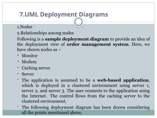
1.Nodes
2.Relationshipsamong nodes
Following is a sample deployment diagram to provide an idea of
the deployment view of order management system. Here, we
have shown nodes as −
Monitor
Modem
Caching server
Server
The application is assumed to be a web-based application,
which is deployed in a clustered environment using server 1,
server 2, and server 3. The user connects to the application using
the Internet. The control flows from the caching server to the
clustered environment.
The following deployment diagram has been drawn considering
all the points mentioned above.
7.UML Deployment Diagrams
Usesof Deployment diagrams:
1.To model the hardware topology of a system.
2.To model the embedded system.
3.To model the hardware details for a client/server system.
4.To model the hardware details of a distributed application.
5.For Forward and Reverse engineering.
Now-a-days software applications are very complex in nature.
Software applications can be standalone, web-based, distributed,
mainframe-based and many more. Hence, it is very important to
design the hardware components efficiently.
64.
8.Addressing Design goals
To address the goals of deployment diagrams in UML like
hardware topology, mapping software to hardware, maintenance
and upgrades, performance and scalability planning in
distribution,
The following are the design goals addresses about the
deployment diagrams:
1.Clear Representation of Physical Architecture:
To provide a visual blueprint of the physical hardware setup,
including servers, devices, and network connections. Helps
designers and stakeholders understand how system components are
physically distributed.
2. Mapping Software Artifacts to Nodes:
To explicitly show which software components (executables,
databases, files) are deployed on which hardware nodes. Ensures
clarity on how software interacts with the hardware infrastructure.
65.
8.Addressing Design goals
3.Modeling System Distribution & Communication:
To illustrate how different hardware nodes communicate (e.g., via
protocols like HTTP, TCP/IP). Supports designing effective
communication strategies in distributed systems.
4. Supporting Non-Functional Requirements:
To address system qualities like performance, scalability,
availability, and security through careful deployment planning.
Ensures that the deployment meets system constraints and business
needs.
5. Facilitating Maintenance & Evolution:
To design the deployment in a modular and well-structured manner. It
Simplifies future upgrades, maintenance, and scalability by providing a
clear, adaptable deployment layout.
6.Reducing System Complexity:
To abstract unnecessary details and focus on key physical components
and their relationships. Makes the system easier to understand and
manage during both development and operations.
66.
9.Managing System Design
Organizing the entire process of designing a system to ensure it meets
its intended goals effectively and efficiently is called Managing of
system design.
It is not just about creating the technical architecture but also involves
planning, coordinating, and controlling all the activities, people,
tools, and resources involved in designing the system.
Managing system design = Managing people + processes + tools
+ quality + risks involved in designing a system.
Key Aspects of Managing System Design:
1. Requirement Management
2. Planning and scheduling
3. Team and collaboration management
4. Monitor of design process
5. Quality of risk management
6. Tool and technology management
7. Communication & Documentation
67.
9.Managing System Design
ManagingSystem Design: Overview
1. Understanding Requirements
Gather functional & non-functional requirements
Define clear system goals (scalability, availability, maintainability, etc.)
Stakeholder meetings to align expectations.
2. High-Level Architecture
Decide architectural style (monolith, microservices, serverless, etc.)
Break down the system into components/services
Define APIs, communication protocols, and data flow.
3. Component Design
Detailed design of each module/component
Database schema design
Use of design patterns (Singleton, Factory, Observer, etc.)
4. Tech Stack Selection
Choosing appropriate programming languages, frameworks, databases,
and cloud services based on requirements.
68.
9.Managing System Design
5.Scalability& Performance Considerations
Load balancing, caching strategies, database sharding, partitioning
CDNs, message queues, rate limiting
6. Security Design
Authentication & Authorization
Data encryption (at rest & in transit)
Secure API gateways
7. Monitoring & Maintenance
Logging, monitoring tools (Prometheus, Grafana)
Automated alerts
Regular audits and updates
8.Project & Team Management
Agile/Scrum methodologies
Version control (Git), CI/CD pipelines
Documentation and code reviews
Risk management and change management
69.
9.Managing System Design
Hence,Managing system design is crucial to:
Deliver the right system
On time
Within budget
With high quality
That can grow and adapt in the future.