The document discusses software design fundamentals including:
- Software design transforms user requirements into a suitable form for programming and implementation.
- There are three levels of software design - architectural, high-level, and detailed design. Architectural design identifies system components and interactions at a high level of abstraction. High-level design breaks this down into sub-systems and modules. Detailed design specifies module logic and interfaces.
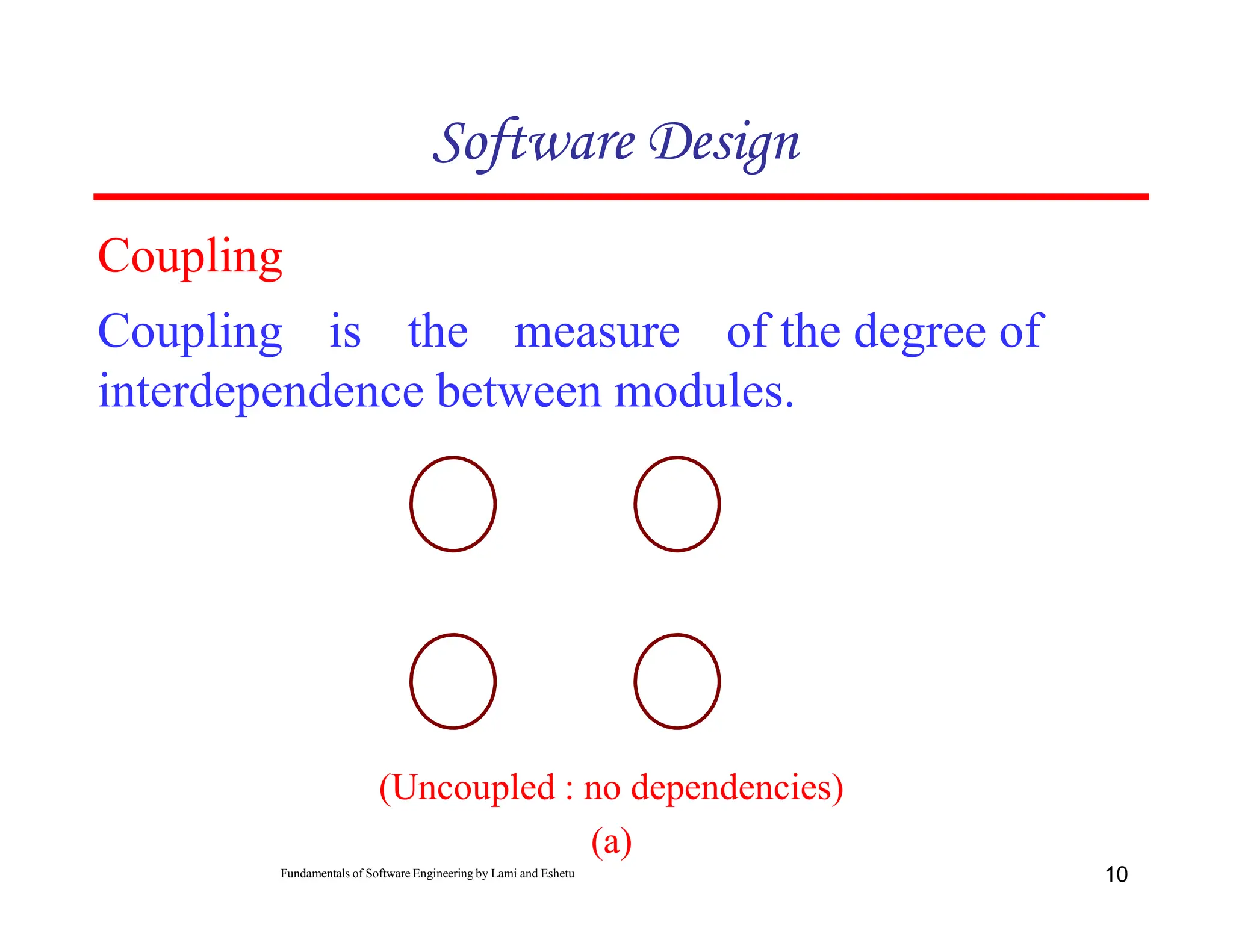
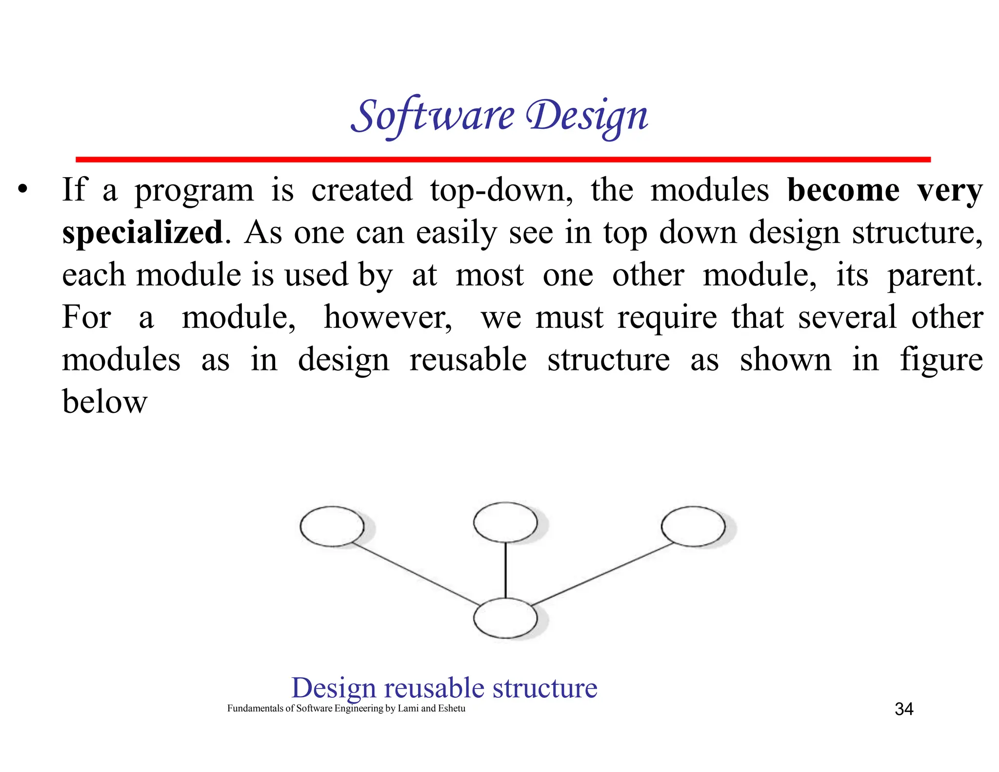
- Good design principles include high cohesion (relatedness of module elements) and loose coupling (few dependencies between modules). Design notations like structure charts and pseudocode can be used to represent the design.