Methods of AnalysisDebretabor University 1
Methods of Analysis
By:-
Tenenet A. (MSc.)
Electromechanical Engineering Department
2018 E.C.
2.
Outline
• Introduction
• Nodalanalysis
• Nodal analysis with voltage source
• Mesh analysis
• Mesh analysis with current source
• Nodal and mesh analyses by inspection
• Nodal versus mesh analysis
3.
Introduction
• Fundamentallaws of circuit theory includes (Ohm’s law and Kirchhoff’s laws),
• By applying these laws we develop two powerful techniques for circuit analysis:
Nodal analysis: which is based on a systematic application of Kirchhoff’s current law (KCL),
Mesh analysis: which is based on a systematic application of Kirchhoff’s voltage law (KVL).
Based on those techniques obtaining a set of simultaneous equations that are solved to obtain the
required values of current or voltage.
The methods of solving simultaneous equations involves;
o Elimination
o Cramer’s rule
4.
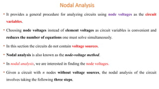
• It providesa general procedure for analyzing circuits using node voltages as the circuit
variables.
• Choosing node voltages instead of element voltages as circuit variables is convenient and
reduces the number of equations one must solve simultaneously.
• In this section the circuits do not contain voltage sources.
• Nodal analysis is also known as the node-voltage method.
• In nodal analysis, we are interested in finding the node voltages.
• Given a circuit with n nodes without voltage sources, the nodal analysis of the circuit
involves taking the following three steps.
Nodal Analysis
5.
Cont …
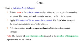
• Stepsto Determine Node Voltages:
1. Select a node as the reference node. Assign voltage v1, v2, …vn-1 to the remaining
n-1 nodes. The voltages are referenced with respect to the reference node.
2. Apply KCL to each of the n-1 non-reference nodes. Use Ohm’s law to express
the branch currents in terms of node voltages.
3. Solve the resulting simultaneous equations to obtain the unknown node
voltages.
Note: The number of non-reference nodes is equal to the number of independent
equations that we will derive.
6.
Debretabor University
Methods ofAnalysis
6
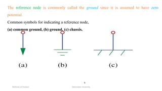
The reference node is commonly called the ground since it is assumed to have zero
potential.
Common symbols for indicating a reference node,
(a) common ground, (b) ground, (c) chassis.
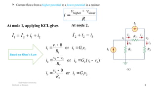
Current flowsfrom a higher potential to a lower potential in a resistor
Debretabor University
Methods of Analysis 8
R
v
v
i lower
higher
2
3
3
3
2
3
2
1
2
2
2
2
1
2
1
1
1
1
1
1
or
0
)
(
or
or
0
v
G
i
R
v
i
v
v
G
i
R
v
v
i
v
G
i
R
v
i
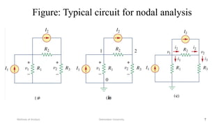
At node 1, applying KCL gives At node 2,
Based on Ohm’s Law
9.
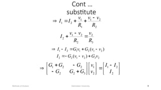
Cont …
substitute
Debretabor University
Methodsof Analysis 9
3
2
2
2
1
2
2
2
1
1
1
2
1
R
v
R
v
v
I
R
v
v
R
v
I
I
2
3
2
1
2
2
2
1
2
1
1
2
1
)
(
)
(
v
G
v
v
G
I
v
v
G
v
G
I
I
2
2
1
2
1
3
2
2
2
2
1
I
I
I
v
v
G
G
G
G
G
G
10.
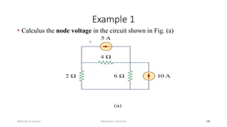
Example 1
• Calculusthe node voltage in the circuit shown in Fig. (a)
Debretabor University
Methods of Analysis 10
11.
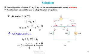
Solution:
At node1: KCL
Debretabor University
Methods of Analysis 11
2
0
4
5 1
2
1
3
2
1
v
v
v
i
i
i
6
0
4
5 2
1
2
5
1
4
2
v
v
v
i
i
i
i
At Node 2: KCL
The assignment of labels (V1, V2, V3, etc.) to the non-reference nodes is entirely arbitrary.
These labels are just variables used to set up the system of equations.
12.
Cont …
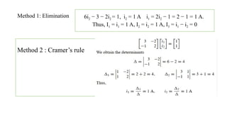
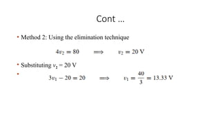
• Method2: Using the elimination technique
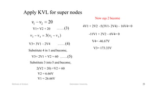
• Substituting v2 = 20 V
•
13.
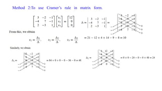
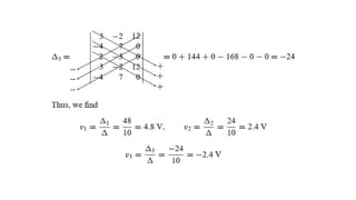
Cont .
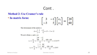
Method 2:Use Cramer’s rule
• In matrix form:
Debretabor University
Methods of Analysis 13
14.
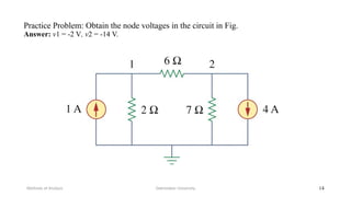
Practice Problem: Obtainthe node voltages in the circuit in Fig.
Answer: v1 = -2 V, v2 = -14 V.
Debretabor University
Methods of Analysis 14
15.
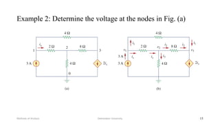
Example 2: Determinethe voltage at the nodes in Fig. (a)
Debretabor University
Methods of Analysis 15
16.
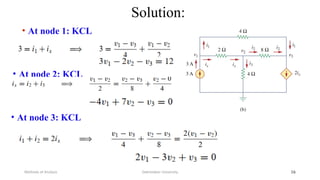
Solution:
• At node1: KCL
Debretabor University
Methods of Analysis 16
• At node 2: KCL
• At node 3: KCL
Nodal Analysis withVoltage Sources
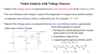
• Case 1: The voltage source is connected between a non-reference node & the reference node:
• The non-reference node voltage is equal to the magnitude of voltage source and the number
of unknown non-reference nodes is reduced by one. For example; V1= 10V
• Case 2: The voltage source is connected between two non-reference nodes: a generalized
node (super-node) is formed.
Debretabor University
Methods of Analysis 20
5
6
0
8
0
4
2
3
2
3
2
3
1
2
1
3
2
4
1
v
v
v
v
v
v
v
v
i
i
i
i
21.
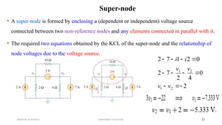
• A super-nodeis formed by enclosing a (dependent or independent) voltage source
connected between two non-reference nodes and any elements connected in parallel with it.
• The required two equations obtained by the KCL of the super-node and the relationship of
node voltages due to the voltage source.
Debretabor University
Methods of Analysis 21
Super-node
2
0
4
2
7
2
0
2
1
7
2
2
1
2
1
v
v
v
v
i
i
22.
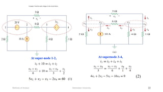
Example: Find thenode voltages in the circuit below.
Debretabor University
Methods of Analysis 22
Mesh Analysis
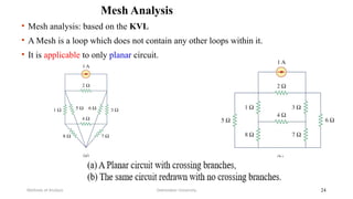
• Meshanalysis: based on the KVL
• A Mesh is a loop which does not contain any other loops within it.
• It is applicable to only planar circuit.
Debretabor University
Methods of Analysis 24
25.
Mesh Analysis
Debretabor University
Methodsof Analysis 25
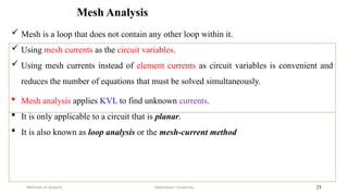
Mesh is a loop that does not contain any other loop within it.
Using mesh currents as the circuit variables.
Using mesh currents instead of element currents as circuit variables is convenient and
reduces the number of equations that must be solved simultaneously.
Mesh analysis applies KVL to find unknown currents.
It is only applicable to a circuit that is planar.
It is also known as loop analysis or the mesh-current method
26.
Mesh Analysis
Debretabor University
Methodsof Analysis 26
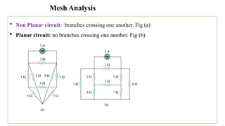
Non Planar circuit: branches crossing one another. Fig (a)
Planar circuit: no branches crossing one another. Fig (b)
27.
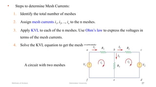
• Steps todetermine Mesh Currents:
1. Identify the total number of meshes
2. Assign mesh currents i1, i2, .., in to the n meshes.
3. Apply KVL to each of the n meshes. Use Ohm’s law to express the voltages in
terms of the mesh currents.
4. Solve the KVL equation to get the mesh currents.
Debretabor University
Methods of Analysis 27
A circuit with two meshes
28.
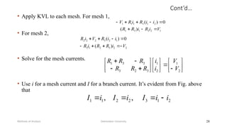
Cont’d…
• Apply KVLto each mesh. For mesh 1,
• For mesh 2,
• Solve for the mesh currents.
• Use i for a mesh current and I for a branch current. It’s evident from Fig. above
that
Debretabor University
Methods of Analysis 28
1
2
3
1
3
1
2
1
3
1
1
1
)
(
0
)
(
V
i
R
i
R
R
i
i
R
i
R
V
2
2
3
2
1
3
1
2
3
2
2
2
)
(
0
)
(
V
i
R
R
i
R
i
i
R
V
i
R
2
1
2
1
3
2
3
3
3
1
V
V
i
i
R
R
R
R
R
R
2
1
3
2
2
1
1 ,
, i
i
I
i
I
i
I
29.
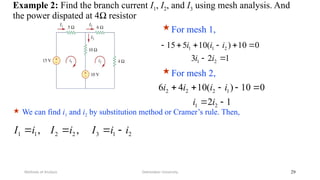
Example 2: Findthe branch current I1, I2, and I3 using mesh analysis. And
the power dispated at 4Ω resistor
Debretabor University
Methods of Analysis 29
For mesh 1,
1
2
3
0
10
)
(
10
5
15
2
1
2
1
1
i
i
i
i
i
For mesh 2,
1
2
0
10
)
(
10
4
6
2
1
1
2
2
2
i
i
i
i
i
i
We can find i1 and i2 by substitution method or Cramer’s rule. Then,
2
1
3
2
2
1
1 ,
, i
i
I
i
I
i
I
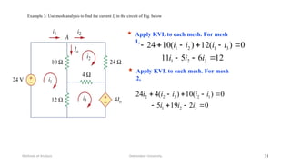
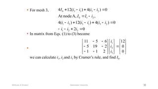
Example 3: Usemesh analysis to find the current I0 in the circuit of Fig. below
Debretabor University
Methods of Analysis 31
Apply KVL to each mesh. For mesh
1,
12
6
5
11
0
)
(
12
)
(
10
24
3
2
1
3
1
2
1
i
i
i
i
i
i
i
Apply KVL to each mesh. For mesh
2,
0
2
19
5
0
)
(
10
)
(
4
24
3
2
1
1
2
3
2
2
i
i
i
i
i
i
i
i
32.
• For mesh3,
• In matrix from Eqs. (1) to (3) become
•
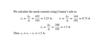
we can calculate i1, i2 and i3 by Cramer’s rule, and find I0.
Debretabor University
Methods of Analysis 32
0
2
0
)
(
4
)
(
12
)
(
4
,
A,
node
At
0
)
(
4
)
(
12
4
3
2
1
2
3
1
3
2
1
2
1
0
2
3
1
3
0
i
i
i
i
i
i
i
i
i
i
I
I
i
i
i
i
I
0
0
12
2
1
1
2
19
5
6
5
11
3
2
1
i
i
i
34.
Mesh Analysis withCurrent Sources
Debretabor University
Methods of Analysis 34
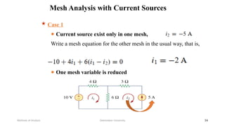
Case 1
● Current source exist only in one mesh,
Write a mesh equation for the other mesh in the usual way, that is,
● One mesh variable is reduced
35.
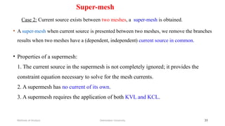
Super-mesh
Case 2: Currentsource exists between two meshes, a super-mesh is obtained.
• A super-mesh when current source is presented between two meshes, we remove the branches
results when two meshes have a (dependent, independent) current source in common.
Debretabor University
Methods of Analysis 35
• Properties of a supermesh:
1. The current source in the supermesh is not completely ignored; it provides the
constraint equation necessary to solve for the mesh currents.
2. A supermesh has no current of its own.
3. A supermesh requires the application of both KVL and KCL.
36.
Debretabor University
Methods ofAnalysis 36
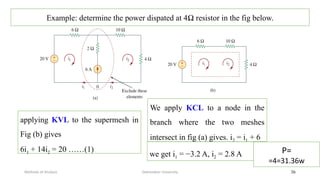
Example: determine the power dispated at 4Ω resistor in the fig below.
applying KVL to the supermesh in
Fig (b) gives
6i1 + 14i2 = 20 ……(1)
We apply KCL to a node in the
branch where the two meshes
intersect in fig (a) gives. i2 = i1 + 6
we get i1 = −3.2 A, i2 = 2.8 A P=
=4=31.36w
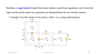
37.
• Example: Forthe circuit in Fig. below,, find i1 to i4 using mesh analysis.
Debretabor University
Methods of Analysis 37
Similarly, a super-mesh formed from three meshes needs three equations: one is from the
super-mesh and the other two equations are obtained from the two current sources.
38.
Debretabor University
Methods ofAnalysis 38
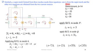
Similarly, a super-mesh formed from three meshes needs three equations: one is from the super-mesh and the
other two equations are obtained from the two current sources
0
10
2
)
(
8
5
0
6
)
(
8
4
2
4
4
3
4
3
2
2
1
2
4
3
3
1
i
i
i
i
i
i
i
i
i
i
i
i
i
Applying KVL in mesh 4,
2i4 + 8(i4 − i3) + 10 = 0 or
5i4 − 4i3 = −5
Hint:
Determinant, Δ=14
Δ1 = -105
Δ2 = -35
Δ3 = 55
Δ4 = 30
39.
Nodal Versus MeshAnalysis
• Both nodal and mesh analyses provide a systematic way of analyzing a complex
network.
• The choice of the better method dictated by two factors.
• First factor: nature of the particular network. The key is to select the method
that results in the smaller number of equations.
• Second factor: information required.
Debretabor University
Methods of Analysis 39
40.
Summary
1. Nodal analysis:the application of KCL at the non-reference nodes
• A circuit has fewer node equations
2. A super-node: two non-reference nodes
3. Mesh analysis: the application of KVL
• A circuit has fewer mesh equations
4. A super-mesh: two meshes
Debretabor University
Methods of Analysis 40

![𝑆𝑜𝑙𝑢𝑡𝑖𝑜𝑛=
[
5 −2 − 3
4 5 0
3 − 6 − 4 ][
𝑣1
𝑣2
𝑣3
]=
[
6 0
0
0 ]](https://image.slidesharecdn.com/chapter3-methodsofanalysis-251205192646-0a57939d/85/Chapter-3-Methods-of-Analysissesd-pptx-19-320.jpg)