Basic Steps in Casting Process (38
•Download as PPTX, PDF•
0 likes•139 views

This document provides information on casting processes and pattern making. It discusses the basic steps in casting including producing parts with complex geometries internally and externally. It then describes the types of patterns used including single piece, split, gated, cope and drag, match plate, loose piece, sweep, skeleton, segmental, and follow board patterns. The document outlines the materials used for patterns including wood, metals and alloys, plastics, and wax. It also discusses allowances provided in patterns for shrinkage, machining, draft, distortion, and rapping. Core types and core making processes are defined. The document explains gating systems and riser components and functions.

Recommended
More Related Content
What's hot
What's hot (20)
Similar to Basic Steps in Casting Process (38
Similar to Basic Steps in Casting Process (38 (20)
Recently uploaded
Recently uploaded (20)
Basic Steps in Casting Process (38
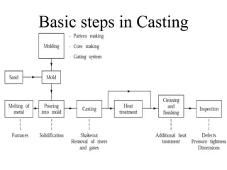
- 1. Basic steps in Casting
- 2. Produce parts with complex geometries, both internally and externally. Possible to net shape with no further manufacturing required. Large parts can be produced. Wide choice of metals. Suitable for mass production. Casting Advantages
- 3. Casting Disadvantages Porosity Poor dimensional control for some processes Poor surface finish for some processes Limitation on mechanical properties Safety hazard Environmental hazard
- 4. Pattern is larger than casting Carries allowances – shrink, machining, draft etc. Carries core prints Patterns may not have all slots and holes which a casting will have Pattern may be in 2 or 3 pieces but casting is in one piece Casting vs. Pattern
- 5. A pattern prepares a mold cavity for the purpose of making a casting. A pattern may contain projections known as core prints if the casting requires a core and need to be made hollow. Runner, gates, and risers used for feeding molten metal in the mold cavity may form a part of the pattern. Patterns properly made and having finished and smooth surfaces reduce casting defects. A properly constructed pattern minimizes the overall cost of the castings. Functions of the Pattern
- 6. Types of Patterns 1. Single piece pattern 2. Split or two piece pattern 3.Gated pattern 4.Cope and drag pattern 5.Match plate pattern 6.Loose piece pattern 7.Sweep pattern 8.Skeleton pattern 9.Segmental pattern 10.Follow board pattern
- 7. 1. Single piece pattern The job is very simple and does not create any withdrawal problems. Most inexpensive of all types of patterns. Very small-scale production or in prototype development. Entirely in the drag and one of the surface is expected to be flat which is used as the parting plane.
- 8. 2. Split or two piece pattern For intricate castings. Split along the parting surface. One half of the pattern is molded in drag and the other half in cope. dowel pins -two halves of the pattern must be aligned properly by making use of the dowel pins, Dowel pins- fitted, to the cope half of the pattern. These dowel pins match with the precisely made holes in the drag half of the pattern
- 9. 3.Gated pattern Simple pattern with gating , runner system. In the mass production of casings, multi cavity molds are used. Such molds are formed by joining a number of patterns and gates and providing a common runner for the molten metal. These patterns are made of metals, and metallic pieces to form gates and runners are attached to the pattern.
- 10. 4. Cope and drag pattern Similar to split pattern Cope and drag halves of pattern along with gating and riser system are attached separately to wooden or metal plates along with alignment pins Cope and drag can be produced separately and assembled Used for heavy and inconvenient for handling
- 12. 5.Match plate pattern Cope and drag along with gating and riser are mounted on single matching metal or wooden plate on either side. On one side of match plate cope flask is prepared & to other side drag flask is prepared. After molding the match plate is removed and complete mold is obtained by joining cope and drag.
- 13. 6.Loose piece pattern Used when contour of part is such that – withdrawing pattern from mold is difficult Obstructing part of pattern is made as loose piece While molding it is held in place While moving main pattern is removed first Loose piece is recovered through gap generated by main pattern
- 14. 7.Sweep pattern For large castings of circular and axis symetric shapes Sweep pattern rotates about the axis or post to sweep shape of casting Reduces cost of pattern E.g. kettles of cast iron
- 15. 8.Skeleton pattern Made up of strips of wood for building final pattern by packing sand around the skeleton After packing sand desired shape is obtained by stickle Used for – turbine casting, water pipe etc.
- 16. 9.Segmental pattern Patterns of this type are generally used for circular castings, for example wheel rim, gear blank etc. Such patterns are sections of a pattern to form a complete mould by being moved to form each section of the mould. The movement of segmental pattern is guided by the use of a central pivot. e.g. segment pattern for a wheel rim
- 17. 10.Follow board pattern When the use of solid or split patterns becomes difficult. The exact shape of one half of the pattern is made in a wooden board, which is called a follow board. It acts as a molding board for the first molding operation.
- 18. Pattern Material Wood, Metals and alloys, Plastic, Wax
- 19. Requirements 1. Easily worked, shaped and joined 2. Light in weight 3. Strong, hard and durable 4. Resistant to wear and abrasion 5. Resistant to corrosion, and to chemical reactions 6. Dimensionally stable and unaffected by variations in temperature and humidity 7. Available at low cost
- 20. Wood is the most popular and commonly used material for pattern making. It is cheap, easily available in large quantity, easily repairable and fabricated in various forms. wooden patterns are preferred only when the numbers of castings to be produced are less. The main varieties of woods used in pattern-making are shisham, white pine, deodar, and mahogany 1. Wood
- 21. Advantages 1 Wood can be easily worked. 2 It is light in weight. 3 It is easily available. 4 It is very cheap. 5 It is easy to join. 6 It is easy to obtain good surface finish. 7 Wooden laminated patterns are strong. 8 It can be easily repaired. Disadvantages 1 It is susceptible to moisture. 2 It tends to warp. 3 It wears out quickly due to sand abrasion. 4 It is weaker than metallic patterns.
- 22. 2. Metals and alloys Metallic patterns are preferred when the number of castings required is large enough to justify their use. These patterns are not much affected by moisture as wooden pattern. The wear and tear of this pattern is very less and hence posses longer life. Moreover, metal is easier to shape the pattern with good precision, surface finish and intricacy in shapes. It can withstand against corrosion and handling for longer period. It possesses excellent strength to weight ratio. The main disadvantages of metallic patterns are higher cost, higher weight and tendency of rusting. The metals commonly used for pattern making are cast iron, brass and bronzes and aluminum alloys.
- 23. Advantages 1 More durable and accurate in size than wooden pattern. 2 Good surface finish. 3 Do not deform in storage. 4 Withstand for rough handling. 5 Good resistance to wear, abrasion and corrosion. Disadvantages 1 Expensive as compared to wood. 2 Heavier than wood. 3 Not easily repaired. 4 Ferrous pattern get rusted.
- 24. Plastics are more popular material in now a days . The plastics used for this purpose are thermosetting resins. Phenolic resin plastics are commonly used. These are prepared with the help of a wooden pattern known as a master pattern. Some other plastic used are polyester, epoxy resin and phenol formaldehyde. 3. Plastics Advantages 1 Light in weight, strong and durable. 2 Smooth surface finish. 3 Good wear resistant. 4 Non sticky to molding sand. Disadvantages 1 less resistant to sudden loading 2 less resistant to heat.
- 25. Patterns made from wax are excellent for investment casting process. The properties desired in a good wax pattern are high tensile strength and hardness, and substantial weld strength. The general practice of making wax pattern is to inject liquid or semi-liquid wax into a split die. 4. Wax Advantages 1 Light in weight. 2 Smooth surface finish. 3 Good dimensional accuracy . 4 Can be reused. Disadvantages 1 Useful for investment casting process. 2 Sticky in nature. Patterns are made from other material like Thermacol rubber etc as per requirement.
- 26. Cast surface as cast– black Cast surface to be machined – red Core print seat – yellow Parting surface – clear or no color Loose piece and seating – Red stripes on yellow base Stop offs or supports – black strips on yellow background Color Coding for Pattern
- 27. Pattern Allowances Pattern allowance is a vital feature as it affects the dimensional characteristics of the casting. The selection of correct allowances greatly helps to reduce machining costs and avoid rejections. 1. Shrinkage or contraction allowance 2. Machining or finish allowance 3. Draft or taper allowance 4. Distortion or camber allowance 5. Shake or Rapping allowance
- 28. Shrinkage or Contraction Allowance All most all cast metals shrink or contract volumetrically on cooling. it refers to the reduction in volume when the metal changes from liquid state to solid state. Rate of contraction with temperature is dependent on the material. Shrinkage depends upon- Metal or alloy Pouring temp Casting dimensions Casting design Molding conditions- material, method
- 29. Grey cast iron- 10.4 mm/m White cast iron -20.8 mm/m Plain Carbon steel-20.8 mm/m Bronze-10.4 to 20.8 mm/m Aluminium-17 mm/m Brass-15.3 mm/m Copper-16mm/m Shrinkage Allowance for Different Materials
- 30. Machining or finish allowance Generally the finish and accuracy achieved in sand casting are poor. Machining- good surface finish or dimensionally accurate. Machining or finish allowances are therefore added in the pattern dimension. The amount of machining allowance to be provided for is affected by the method of molding and casting used viz. hand molding or machine molding, sand casting or metal mold casting. The amount of machining allowance is also affected by the size and shape of the casting; the casting orientation; the metal; and the degree of accuracy and finish required.
- 31. Metal Size Allowance (mm) Cast Iron Medium Large 3 10 Cast Steel Medium Large 4.5 12 Non- Ferrous Medium Large 1.5 5
- 32. Draft or taper allowance • The taper allowance is provided on all vertical surfaces of the pattern • So that it can be removed from the sand without tearing the sides of the sand mold. Without allowance With allowance
- 33. Draft allowance varies the complexity of the sand job. But in general inner sides of the pattern require higher draft than outer sides. The amount of draft depends upon the length of the vertical side of the pattern. For External Surface 10 to 25 mm/meter For Internal Surface 40 to 65 mm/meter
- 34. Distortion or camber allowance The distortion in casting may occur due to internal stresses. These internal stresses are caused on account of unequal cooling of different section of the casting. for long and flat casting. For Unequal Thickness.
- 35. Shake or Rapping allowance • Before the withdrawal from the sand mold, the pattern is rapped all around the vertical faces to enlarge the mold cavity slightly, which facilitate its removal. • Rapping enlarges the final casting. • So it is desirable that the original pattern dimension should be reduced to account for this increase. • It is a negative allowance and is to be applied only to those dimensions that are parallel to the parting plane.
- 36. Selection Criteria for Pattern
- 37. Core Strong , permeable, refractory, low residual gas forming, collapsible Sand plus binder Sand with low clay or clay free
- 38. Core making Core sand preparation – Sand plus binder Core molding – core box, ramming, Core making machines – a. core blowing b. core ramming Core baking – baked to remove moisture and get strength – 1500 to 4000 C. Core finishing – smoothed, pasting with dextrin or water soluble binders. core dressing with fine refractory coating or core wash (ground graphite, silica, zircon).
- 39. Core Box • Core box is nothing but pattern for core. • Core boxes are used for ramming core Sand. • It may be made by wooden or by metal.
- 40. Types of Core Boxes 1. Half Core Box- It is used for cylindrical cores & only half portion is made at one time. 2. Slab or Dump Core Box- It is used for rectangular, square cores & made full core at one time. 3. Split Core Box- It is having two halves & made full core at one time. 4. Left and Right hand Core Box- It is used for making cores of pipe bend & only half portion is made at one time. 5. Gang Core Box-It contain no of cavities so that it can prepare no of cores at one time.
- 41. Types of Cores 1. Based on condition of core- 1.green sand core 2. dry sand core 2. Based on Nature of binder materials- 1.oil bonded core 2. resin bonded core 3. shell core 4. sodium silicate core 3. Based on core hardening process- 1.CO2 process 2.hot box process 3. cold set process 4. oil-no-bake core 4. Based on position of core- 1. horizontal core 2. vertical core 3.hanging core 4.balanced core 5.drop-off core 6.ram-up core
- 42. 1. Horizontal core Horizontal position, Usually cylindrical at parting plane. Core rest in seats provided by core print on pattern 2. Vertical core Vertical position Both in cope and drag Top and bottom provided with taper - alignment
- 43. 3.Hanging core Hanging position Core hangs from cope and no support at bottom of drug 4.Balanced core Balanced Opening on one side of casting Only one core print Core print is made large to balance the weight and sufficient support
- 44. 5.Drop-off core When hole is required in casting above or below the parting line Side of core is given sufficient amount of taper so core can be placed easily Also called as stop-off core, tail core, chair or saddle core 6.Ram-up core Ram – up Setting the core before mould is rammed. Core details located in accessible position
- 45. Components of Gating system
- 47. Gate Ratio Definition- It is defined as the ratio of sprue base area followed by total runner area and total ingate area. Types of gating Ratio 1) Non pressurized gating system- The typical gating system is 1:2:4 or 1:3:3.This is used for light metals like Al, Cu etc. 2) Pressurized gating system- The typical gating system is 1:2:1 or 4:8:3. This is used for heavy metals like CI, Steel etc
- 48. Riser Function of Riser- 1. It acts as reservoir during solidification to feed molten metal towards cavity. 2. A riser indicates that the mold cavity has already filled. 3. A riser permits the escape for air and gases. 4. Riser promote directional solidification. Types of Riser- 1. Open riser 2. Blind riser
- 50. Riser efficiency Definition- It is defined as the amount of molten metal supplied by riser to mold cavity. 𝑒 = 𝐼−𝐹 𝐼 x 100 Where I=Initial volume of metal in riser F=Final volume of metal in riser I-F=The amount of molten metal supplied by riser to mold cavity. As solidification in casting & in riser start at same time therefore efficiency may low. To increase efficiency of riser solidification in casting require to start early or solidification in riser require to start latter.
- 51. Methods to improve Riser efficiency 1. Careful design and location of riser. 2. Use of insulating material. 3. Exothermic materials. 4. Chills (internal & external). 5. Padding.