2
Chapter 2 Objectives
•Understand the fundamentals of numerical data
representation and manipulation in digital
computers.
• Master the skill of converting between various
radix systems.
• Understand how errors can occur in computations
because of overflow and truncation.
3.
3
• Understand thefundamental concepts of floating-
point representation.
• Gain familiarity with the most popular character
codes.
• Understand the concepts of error detecting and
correcting codes.
Chapter 2 Objectives
4.
4
2.1 Introduction
• Abit is the most basic unit of information in a
computer.
– It is a state of “on” or “off” in a digital circuit.
– Sometimes these states are “high” or “low” voltage
instead of “on” or “off..”
• A byte is a group of eight bits.
– A byte is the smallest possible addressable unit of
computer storage.
– The term, “addressable,” means that a particular byte can
be retrieved according to its location in memory.
5.
5
• A wordis a contiguous group of bytes.
– Words can be any number of bits or bytes.
– Word sizes of 16, 32, or 64 bits are most common.
– In a word-addressable system, a word is the smallest
addressable unit of storage.
• A group of four bits is called a nibble.
– Bytes, therefore, consist of two nibbles: a “high-order
nibble,” and a “low-order” nibble.
2.1 Introduction
6.
6
2.2 Positional NumberingSystems
• Bytes store numbers using the position of each
bit to represent a power of 2.
– The binary system is also called the base-2 system.
– Our decimal system is the base-10 system. It uses
powers of 10 for each position in a number.
– Any integer quantity can be represented exactly using
any base (or radix).
7.
7
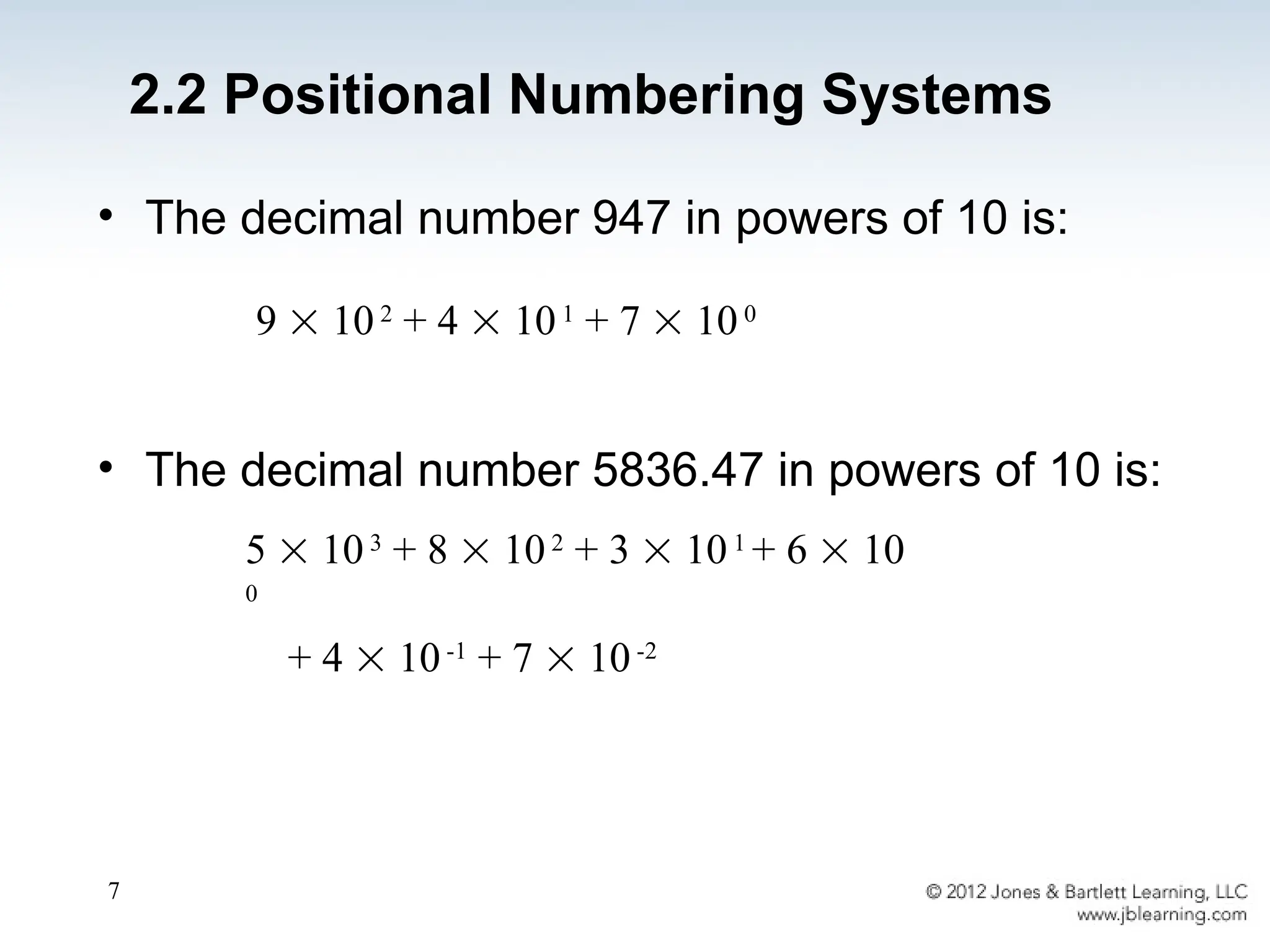
• The decimalnumber 947 in powers of 10 is:
• The decimal number 5836.47 in powers of 10 is:
5 103
+ 8 102
+ 3 101
+ 6 10
0
+ 4 10-1
+ 7 10-2
9 102
+ 4 101
+ 7 100
2.2 Positional Numbering Systems
8.
8
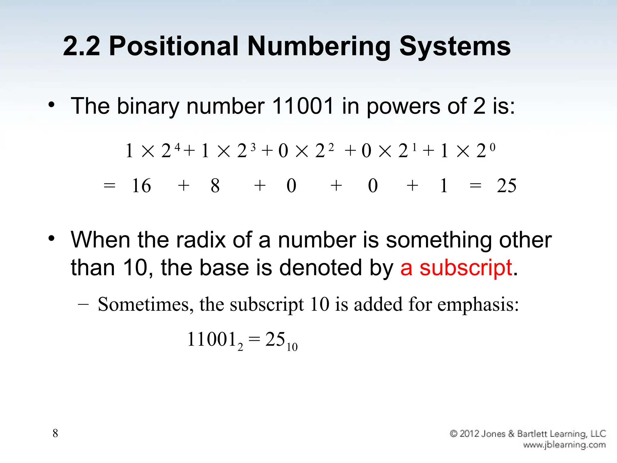
• The binarynumber 11001 in powers of 2 is:
• When the radix of a number is something other
than 10, the base is denoted by a subscript.
– Sometimes, the subscript 10 is added for emphasis:
110012 = 2510
1 24
+ 1 23
+ 0 22
+ 0 21
+ 1 20
= 16 + 8 + 0 + 0 + 1 = 25
2.2 Positional Numbering Systems
9.
9
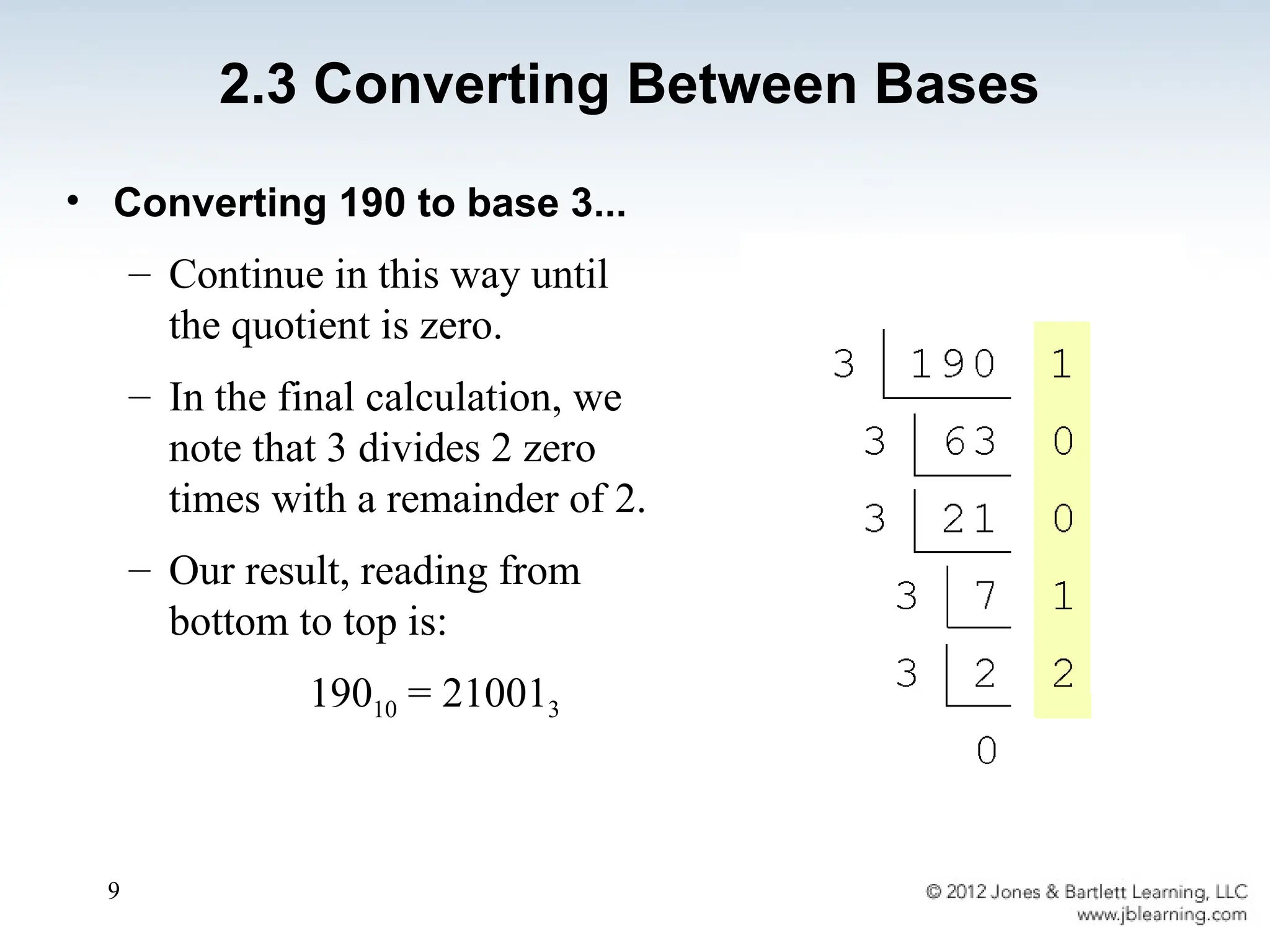
• Converting 190to base 3...
– Continue in this way until
the quotient is zero.
– In the final calculation, we
note that 3 divides 2 zero
times with a remainder of 2.
– Our result, reading from
bottom to top is:
19010 = 210013
2.3 Converting Between Bases
11
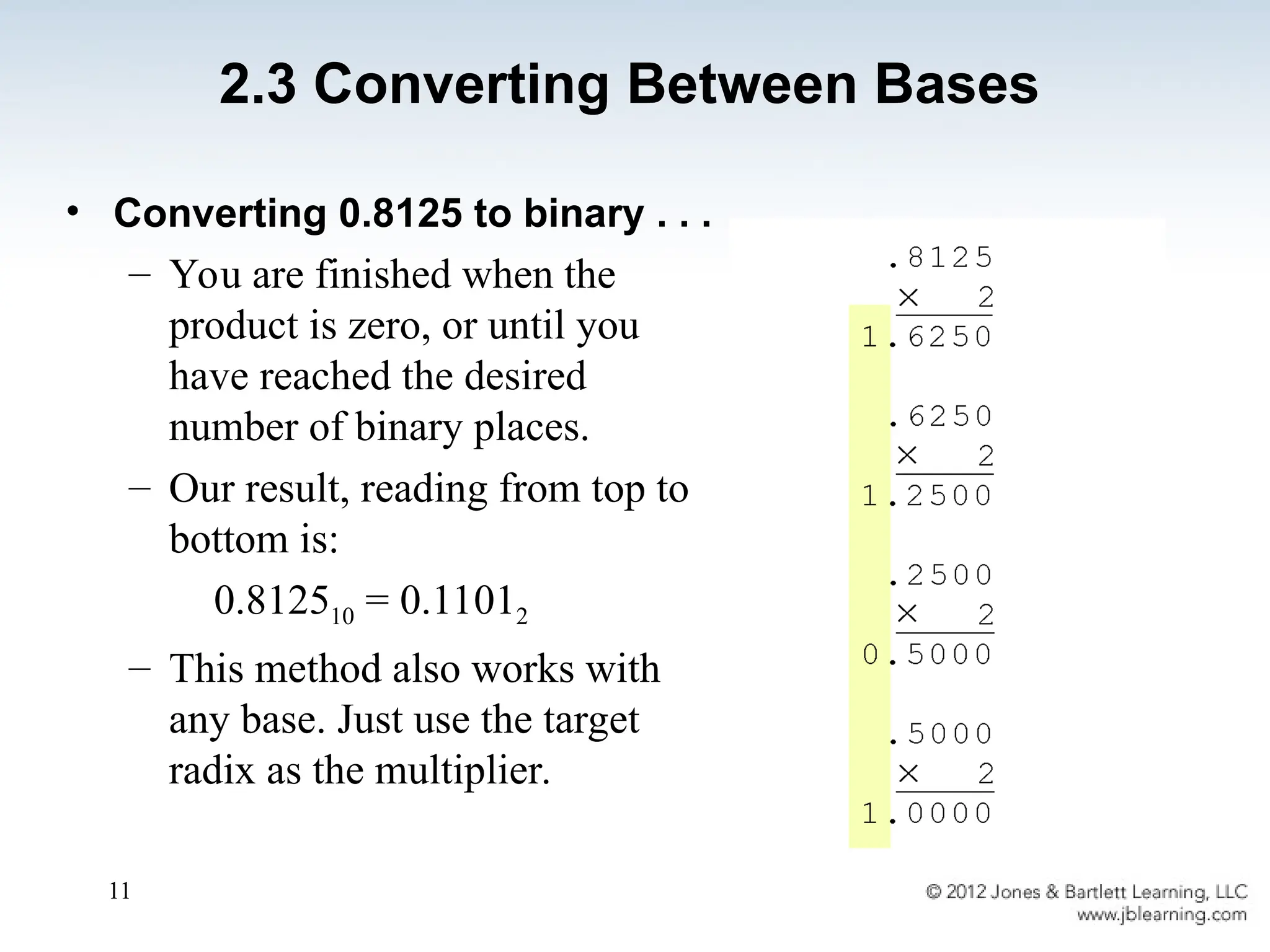
• Converting 0.8125to binary . . .
– You are finished when the
product is zero, or until you
have reached the desired
number of binary places.
– Our result, reading from top to
bottom is:
0.812510 = 0.11012
– This method also works with
any base. Just use the target
radix as the multiplier.
2.3 Converting Between Bases
12.
12
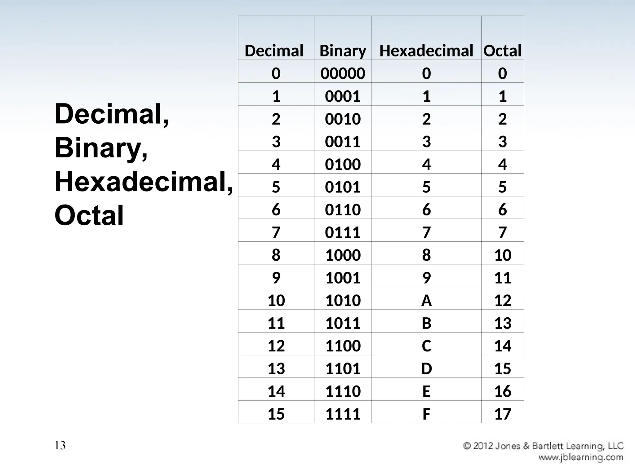
• The binarynumbering system is the most
important radix system for digital computers.
• However, it is difficult to read long strings of binary
numbers -- and even a modestly-sized decimal
number becomes a very long binary number.
– For example: 110101000110112 = 1359510
• For compactness and ease of reading, binary
values are usually expressed using the
hexadecimal, or base-16, numbering system.
2.3 Converting Between Bases
14
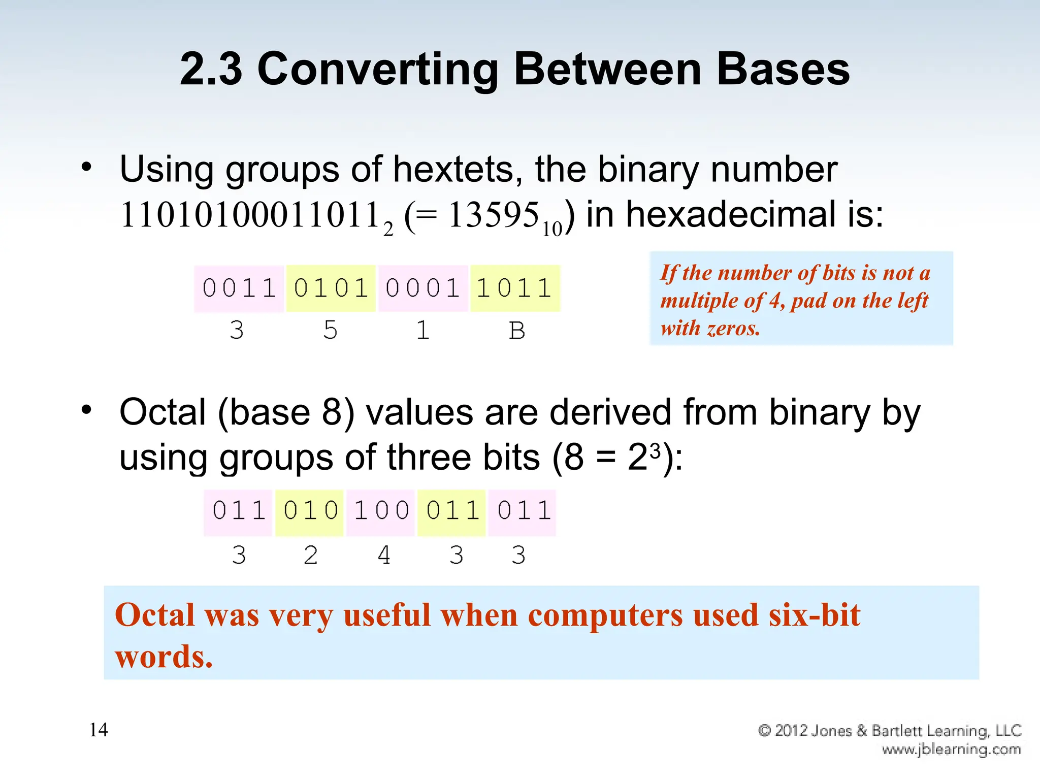
• Using groupsof hextets, the binary number
110101000110112 (= 1359510) in hexadecimal is:
• Octal (base 8) values are derived from binary by
using groups of three bits (8 = 23
):
Octal was very useful when computers used six-bit
words.
If the number of bits is not a
multiple of 4, pad on the left
with zeros.
2.3 Converting Between Bases
15.
15
2.4 Signed IntegerRepresentation
• The conversions we have so far presented have
involved only unsigned numbers.
• To represent signed integers, computer systems
allocate the high-order bit to indicate the sign of a
number.
– The high-order bit is the leftmost bit. It is also called the
most significant bit.
– 0 is used to indicate a positive number; 1 indicates a
negative number.
• The remaining bits contain the value of the number
(but this can be interpreted different ways)
16.
16
• There arethree ways in which signed binary
integers may be expressed:
– Signed magnitude
– One’s complement
– Two’s complement
• In an 8-bit word, signed magnitude
representation places the absolute value of
the number in the 7 bits to the right of the
sign bit.
2.4 Signed Integer Representation
17.
17
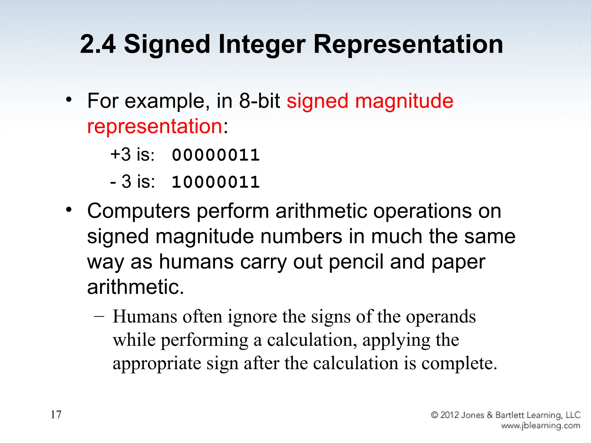
• For example,in 8-bit signed magnitude
representation:
+3 is: 00000011
- 3 is: 10000011
• Computers perform arithmetic operations on
signed magnitude numbers in much the same
way as humans carry out pencil and paper
arithmetic.
– Humans often ignore the signs of the operands
while performing a calculation, applying the
appropriate sign after the calculation is complete.
2.4 Signed Integer Representation
18.
18
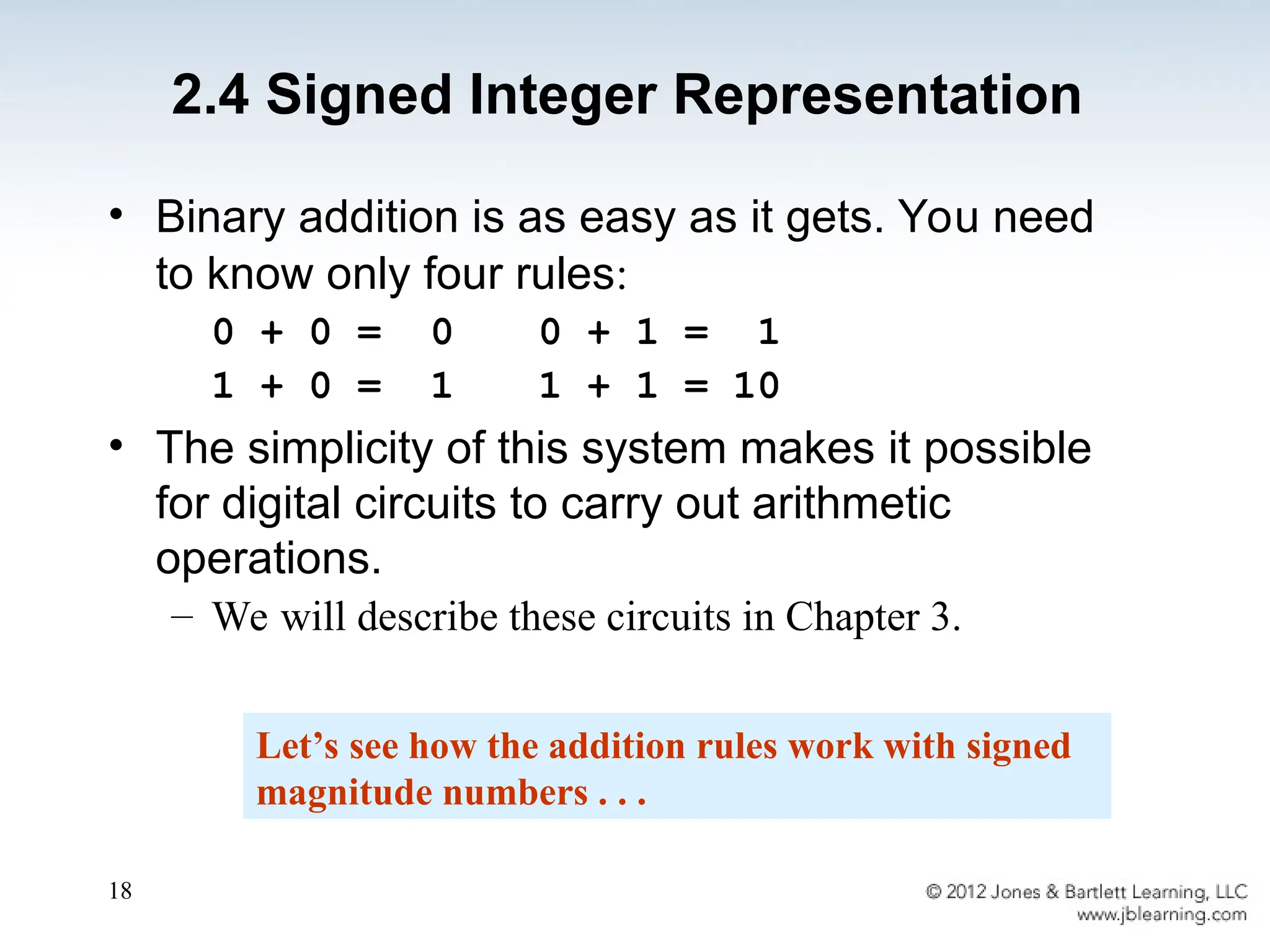
• Binary additionis as easy as it gets. You need
to know only four rules:
0 + 0 = 0 0 + 1 = 1
1 + 0 = 1 1 + 1 = 10
• The simplicity of this system makes it possible
for digital circuits to carry out arithmetic
operations.
– We will describe these circuits in Chapter 3.
Let’s see how the addition rules work with signed
magnitude numbers . . .
2.4 Signed Integer Representation
19.
19
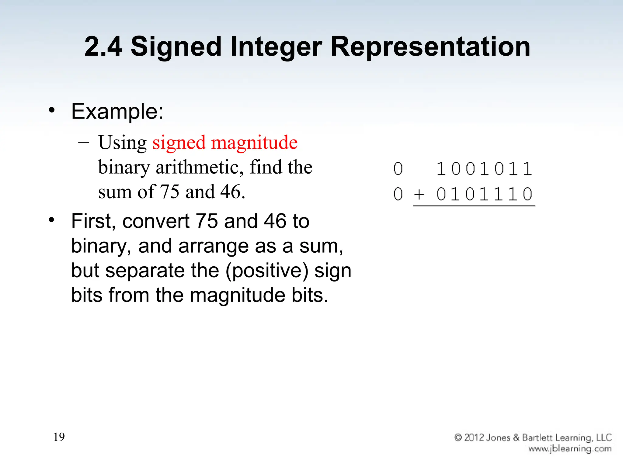
• Example:
– Usingsigned magnitude
binary arithmetic, find the
sum of 75 and 46.
• First, convert 75 and 46 to
binary, and arrange as a sum,
but separate the (positive) sign
bits from the magnitude bits.
2.4 Signed Integer Representation
20.
20
• Signed magnituderepresentation is easy for
people to understand, but it requires
complicated computer hardware.
• Another disadvantage of signed magnitude is
that it allows two different representations for
zero: positive zero and negative zero.
• For these reasons (among others) computers
systems employ complement systems for
numeric value representation.
2.4 Signed Integer Representation
21.
21
• In complementsystems, negative values are
represented by some difference between a
number and its base.
• The diminished radix complement of a non-zero
number N in base r with d digits is (rd
– 1) – N
• In the binary system, this gives us one’s
complement. It amounts to little more than flipping
the bits of a binary number.
2.4 Signed Integer Representation
22.
22
• For example,using 8-bit one’s complement
representation:
+ 3 is: 00000011
- 3 is: 11111100
• In one’s complement representation, as with
signed magnitude, negative values are
indicated by a 1 in the high order bit.
• Complement systems are useful because they
eliminate the need for subtraction. The
difference of two values is found by adding the
minuend to the complement of the subtrahend.
2.4 Signed Integer Representation
23.
23
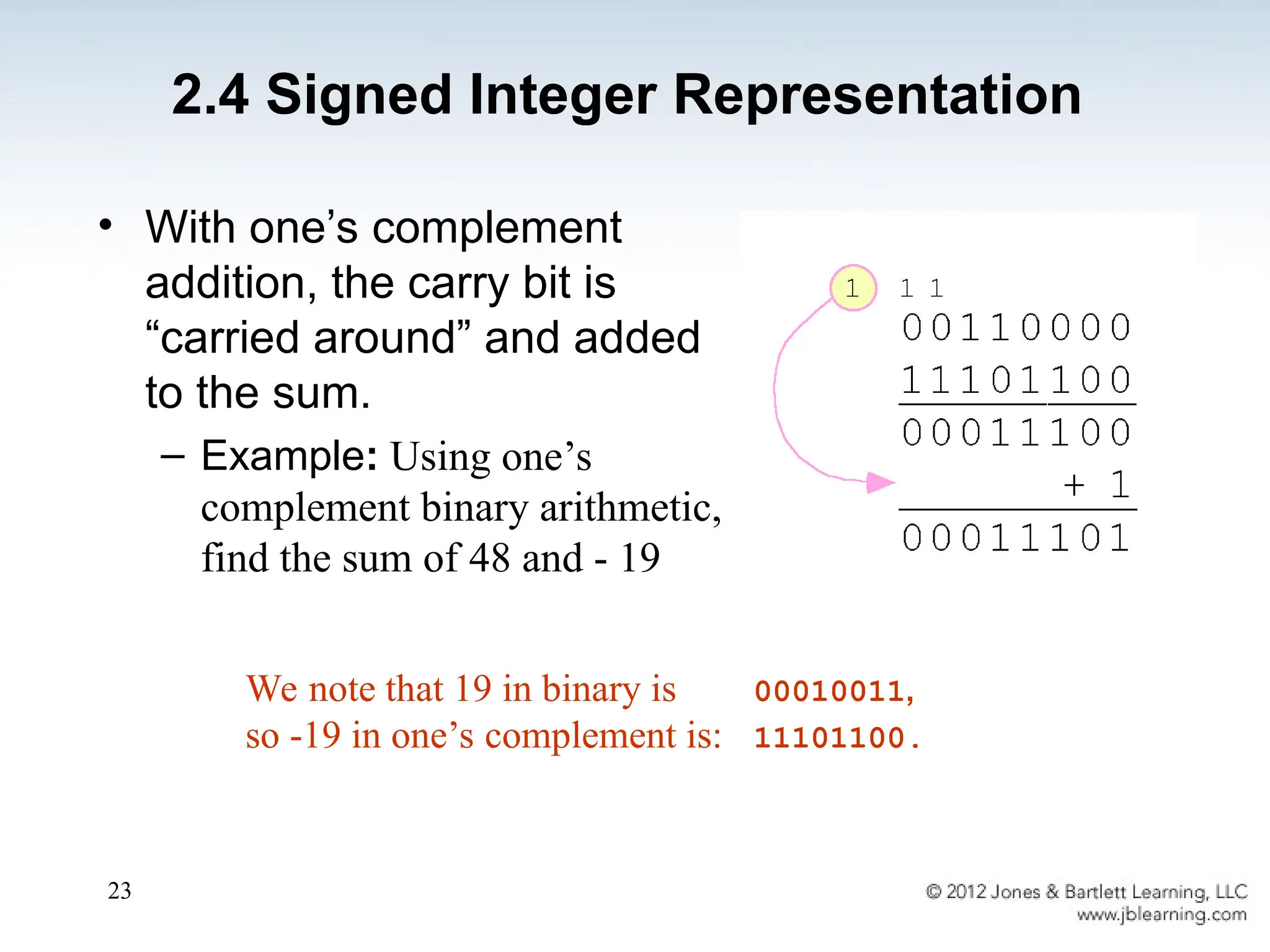
• With one’scomplement
addition, the carry bit is
“carried around” and added
to the sum.
– Example: Using one’s
complement binary arithmetic,
find the sum of 48 and - 19
We note that 19 in binary is 00010011,
so -19 in one’s complement is: 11101100.
2.4 Signed Integer Representation
24.
24
• Although the“end carry around” adds some
complexity, one’s complement is simpler to
implement than signed magnitude.
• But it still has the disadvantage of having two
different representations for zero: positive zero and
negative zero.
• Two’s complement solves this problem.
• Two’s complement is the radix complement of the
binary numbering system; the radix complement of a
non-zero number N in base r with d digits is rd
– N.
2.4 Signed Integer Representation
25.
25
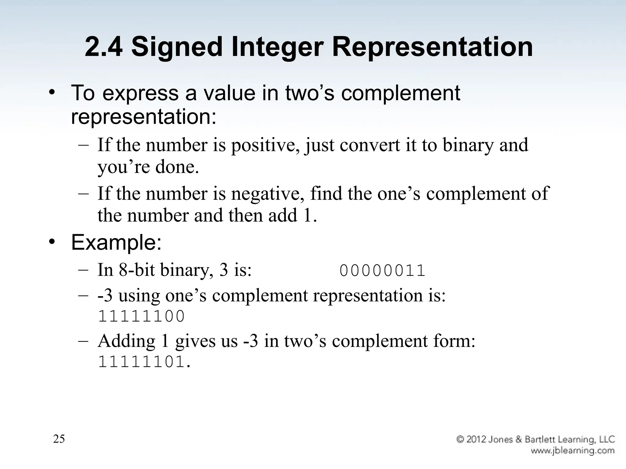
• To expressa value in two’s complement
representation:
– If the number is positive, just convert it to binary and
you’re done.
– If the number is negative, find the one’s complement of
the number and then add 1.
• Example:
– In 8-bit binary, 3 is: 00000011
– -3 using one’s complement representation is:
11111100
– Adding 1 gives us -3 in two’s complement form:
11111101.
2.4 Signed Integer Representation
26.
26
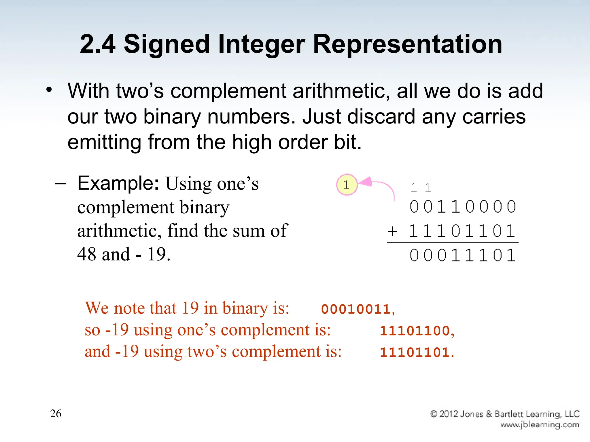
• With two’scomplement arithmetic, all we do is add
our two binary numbers. Just discard any carries
emitting from the high order bit.
We note that 19 in binary is: 00010011,
so -19 using one’s complement is: 11101100,
and -19 using two’s complement is: 11101101.
– Example: Using one’s
complement binary
arithmetic, find the sum of
48 and - 19.
2.4 Signed Integer Representation
27.
27
• When weuse any finite number of bits to
represent a number, we always run the risk of
the result of our calculations becoming too large
or too small to be stored in the computer.
• While we can’t always prevent overflow, we can
always detect overflow.
• In complement arithmetic, an overflow condition
is easy to detect.
2.4 Signed Integer Representation
28.
28
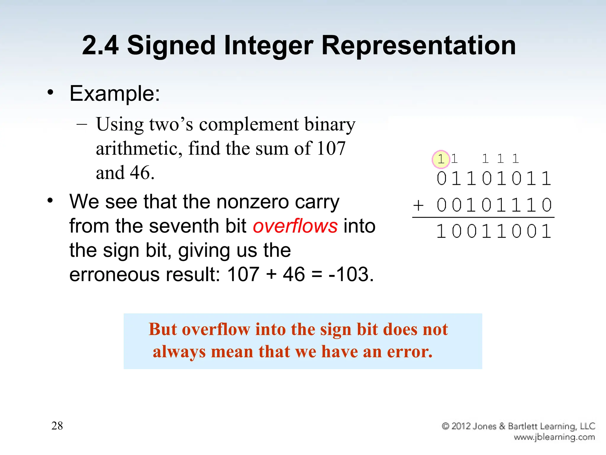
• Example:
– Usingtwo’s complement binary
arithmetic, find the sum of 107
and 46.
• We see that the nonzero carry
from the seventh bit overflows into
the sign bit, giving us the
erroneous result: 107 + 46 = -103.
But overflow into the sign bit does not
always mean that we have an error.
2.4 Signed Integer Representation
29.
29
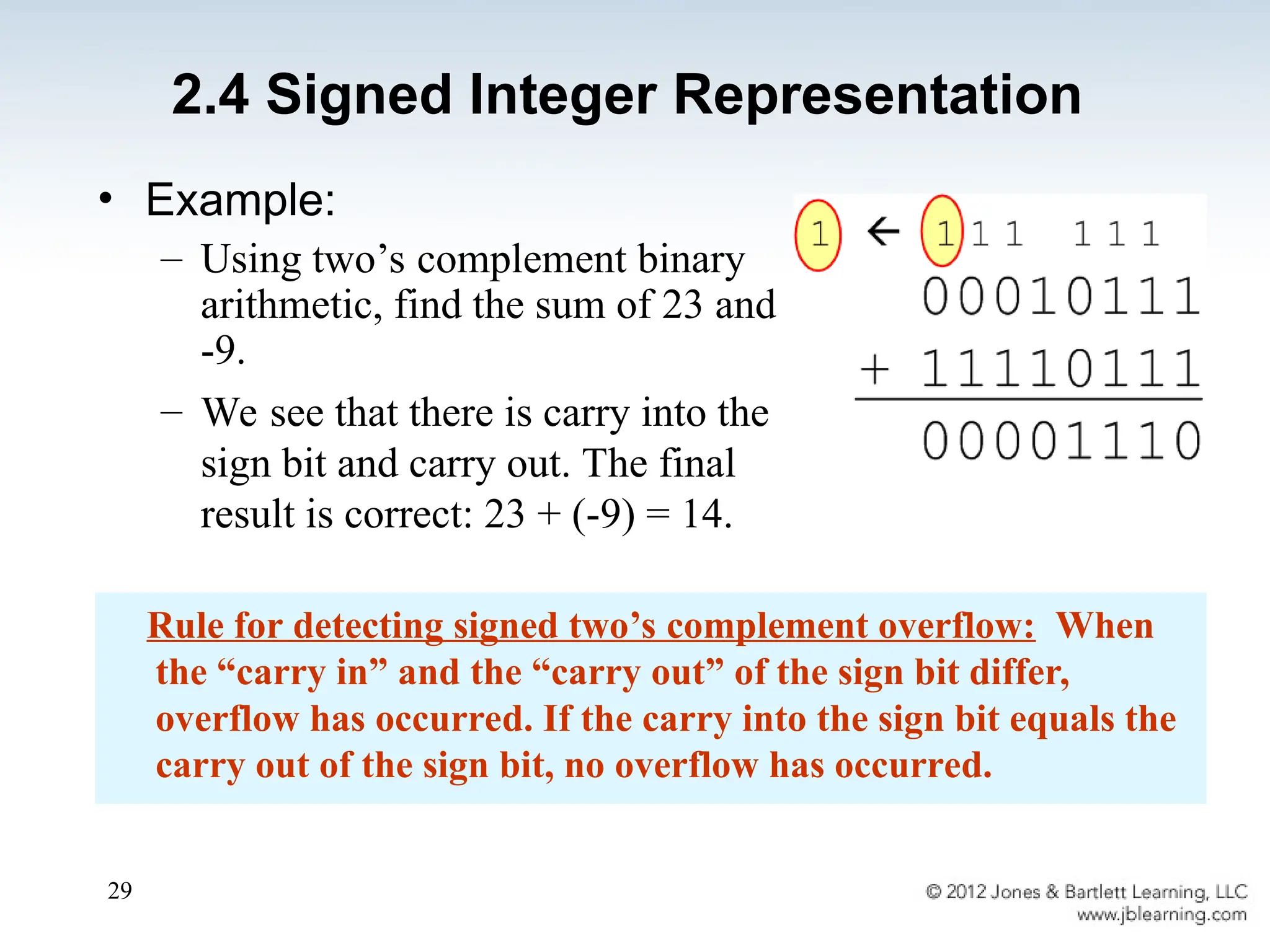
• Example:
– Usingtwo’s complement binary
arithmetic, find the sum of 23 and
-9.
– We see that there is carry into the
sign bit and carry out. The final
result is correct: 23 + (-9) = 14.
Rule for detecting signed two’s complement overflow: When
the “carry in” and the “carry out” of the sign bit differ,
overflow has occurred. If the carry into the sign bit equals the
carry out of the sign bit, no overflow has occurred.
2.4 Signed Integer Representation
30.
30
• The signedmagnitude, one’s complement,
and two’s complement representation that we
have just presented deal with signed integer
values only.
• Without modification, these formats are not
useful in scientific or business applications
that deal with real number values.
• Floating-point representation solves this
problem.
2.5 Floating-Point Representation
31.
31
2.5 Floating-Point Representation
•If we are clever programmers, we can perform
floating-point calculations using any integer format.
• This is called floating-point emulation, because
floating point values aren’t stored as such; we just
create programs that make it seem as if floating-
point values are being used.
• Most of today’s computers are equipped with
specialized hardware that performs floating-point
arithmetic with no special programming required.
32.
32
• Floating-point numbersallow an arbitrary
number of decimal places to the right of the
decimal point.
– For example: 0.5 0.25 = 0.125
• They are often expressed in scientific notation.
– For example:
0.125 = 1.25 10-1
5,000,000 = 5.0 106
2.5 Floating-Point Representation
33.
33
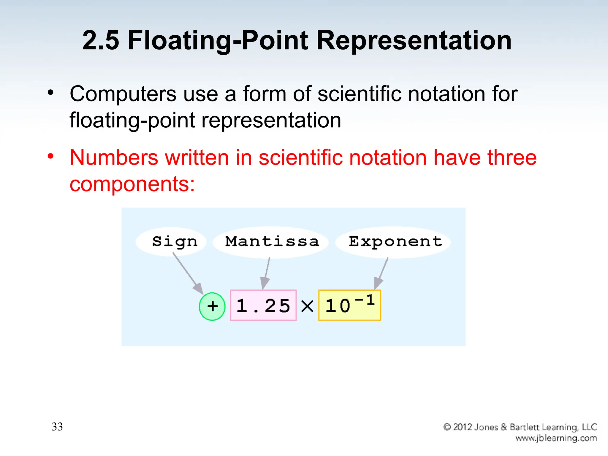
• Computers usea form of scientific notation for
floating-point representation
• Numbers written in scientific notation have three
components:
2.5 Floating-Point Representation
34.
34
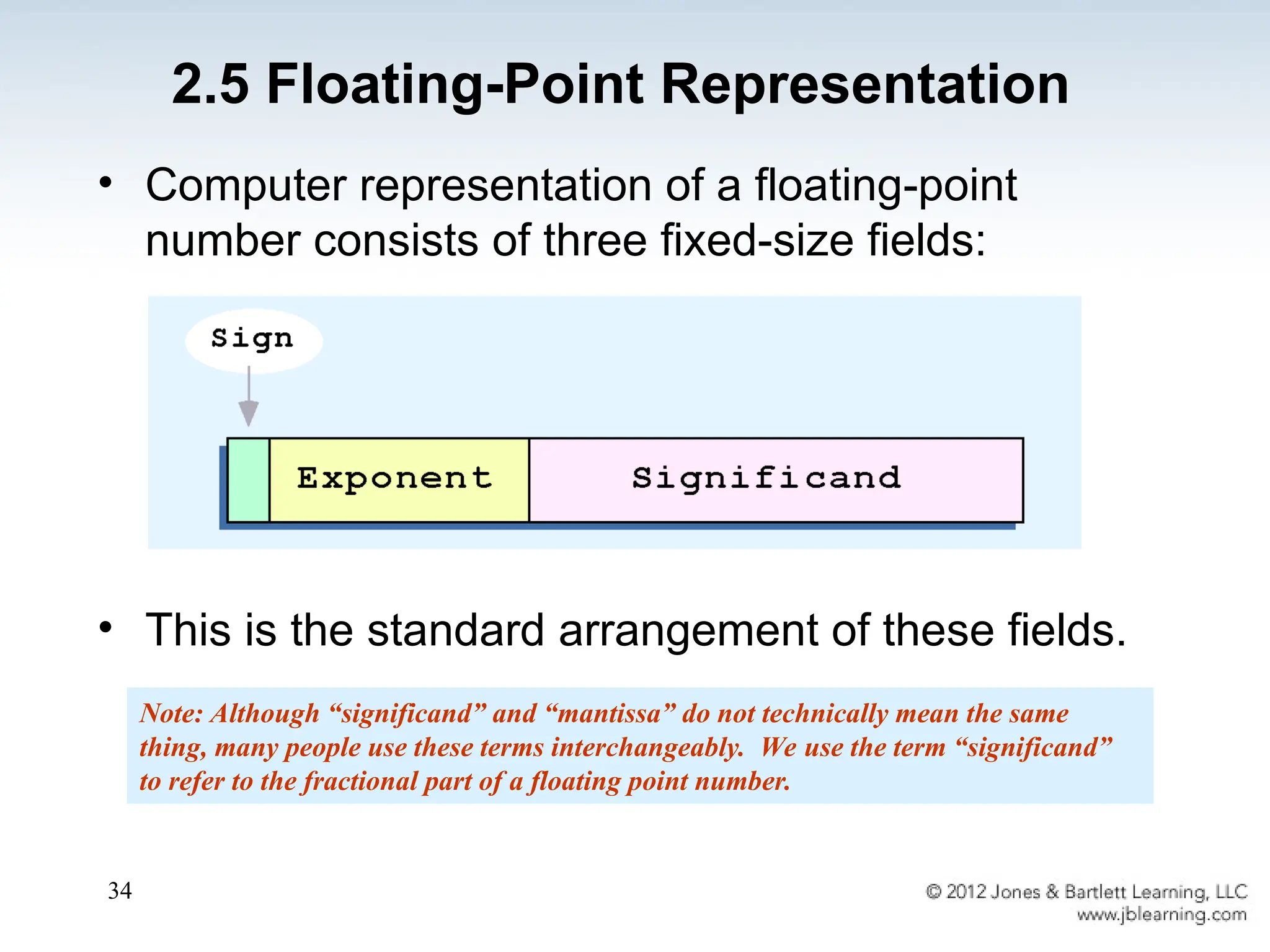
• Computer representationof a floating-point
number consists of three fixed-size fields:
• This is the standard arrangement of these fields.
Note: Although “significand” and “mantissa” do not technically mean the same
thing, many people use these terms interchangeably. We use the term “significand”
to refer to the fractional part of a floating point number.
2.5 Floating-Point Representation
35.
35
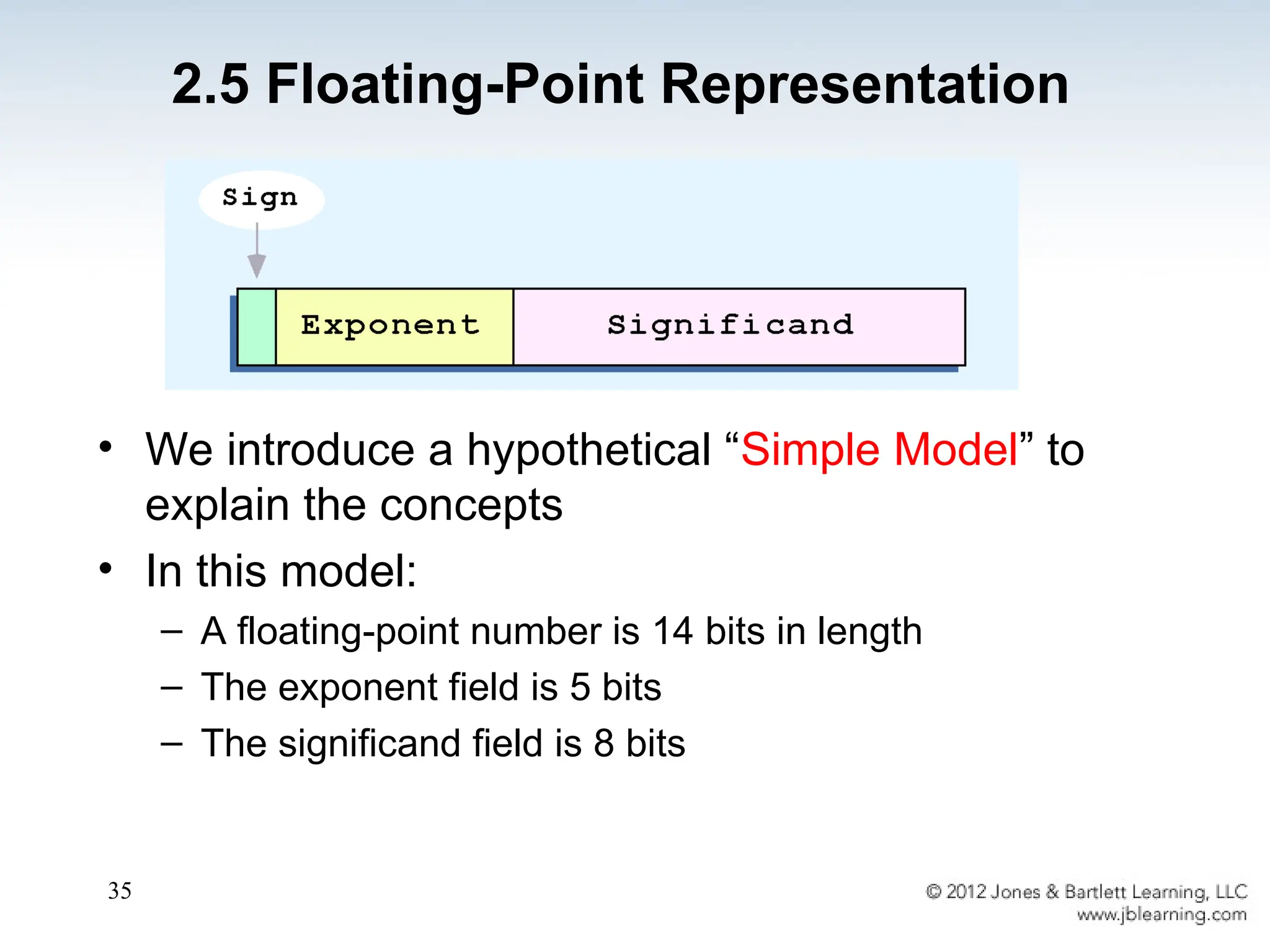
• We introducea hypothetical “Simple Model” to
explain the concepts
• In this model:
– A floating-point number is 14 bits in length
– The exponent field is 5 bits
– The significand field is 8 bits
2.5 Floating-Point Representation
36.
36
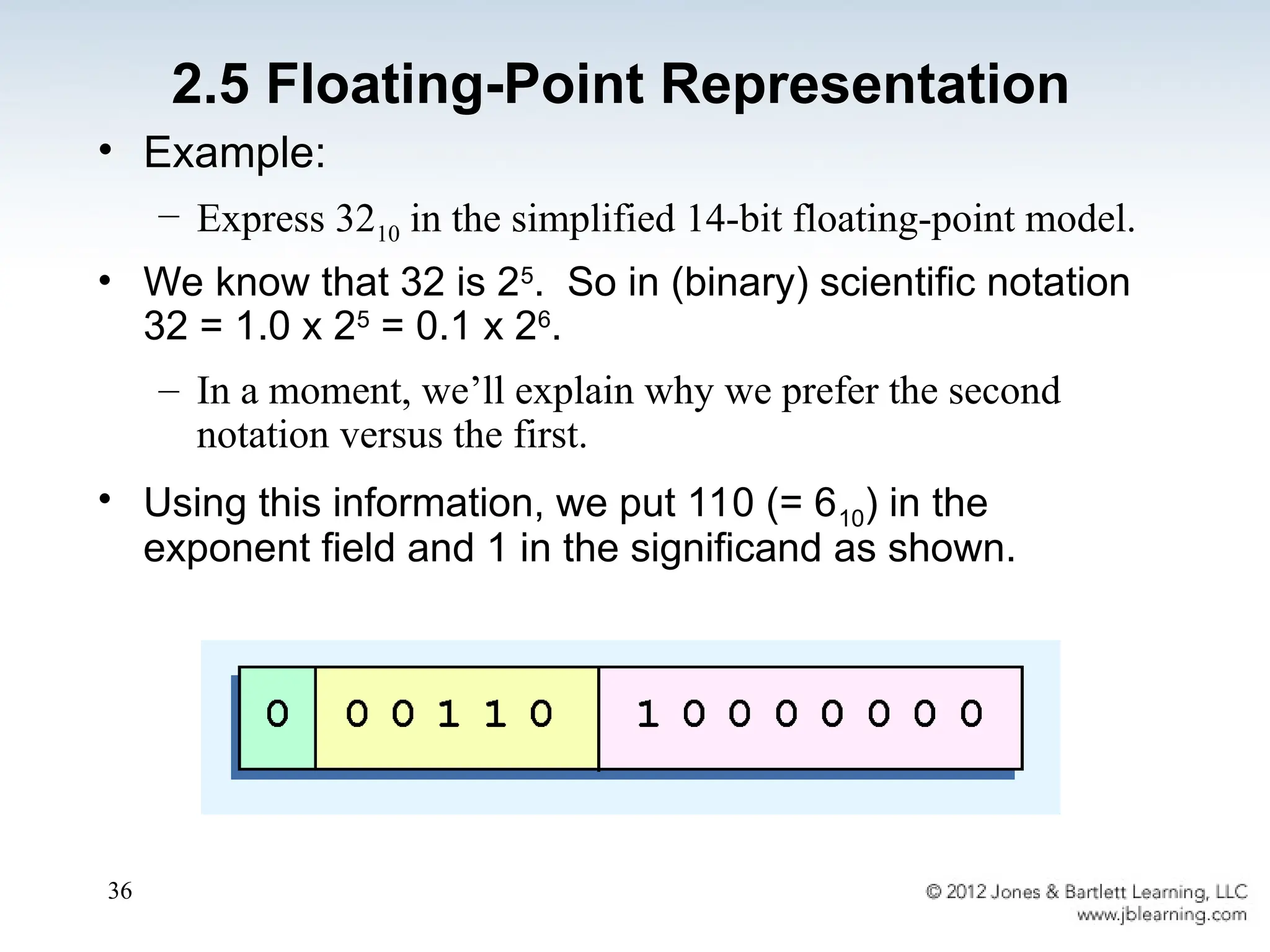
• Example:
– Express3210 in the simplified 14-bit floating-point model.
• We know that 32 is 25
. So in (binary) scientific notation
32 = 1.0 x 25
= 0.1 x 26
.
– In a moment, we’ll explain why we prefer the second
notation versus the first.
• Using this information, we put 110 (= 610) in the
exponent field and 1 in the significand as shown.
2.5 Floating-Point Representation
37.
37
• The IEEEhas established a standard for
floating-point numbers
• The IEEE-754 single precision floating point
standard uses an 8-bit exponent (with a bias of
127) and a 23-bit significand.
• The IEEE-754 double precision standard uses
an 11-bit exponent (with a bias of 1023) and a
52-bit significand.
2.5 Floating-Point Representation
38.
38
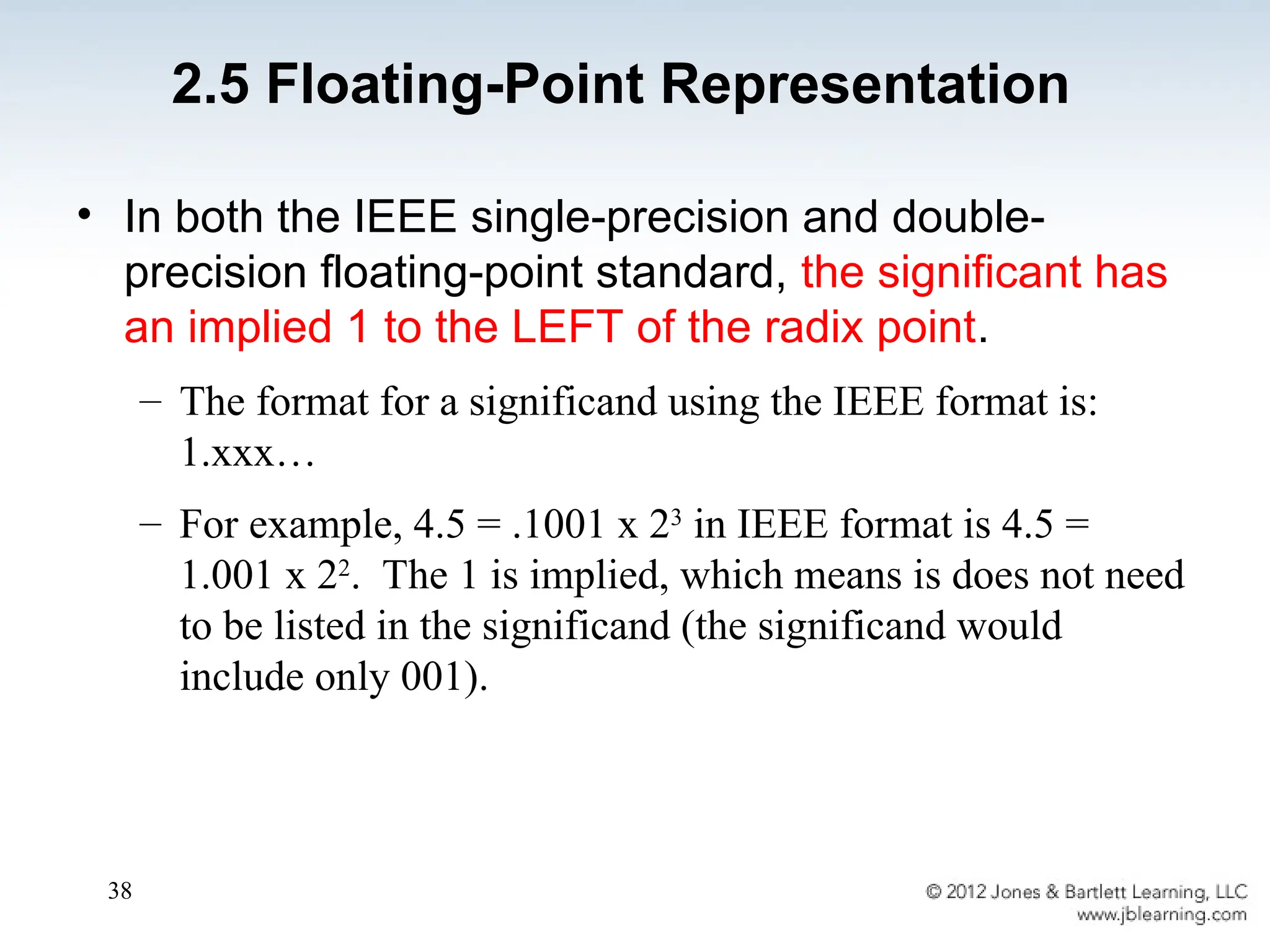
• In boththe IEEE single-precision and double-
precision floating-point standard, the significant has
an implied 1 to the LEFT of the radix point.
– The format for a significand using the IEEE format is:
1.xxx…
– For example, 4.5 = .1001 x 23
in IEEE format is 4.5 =
1.001 x 22
. The 1 is implied, which means is does not need
to be listed in the significand (the significand would
include only 001).
2.5 Floating-Point Representation
39.
39
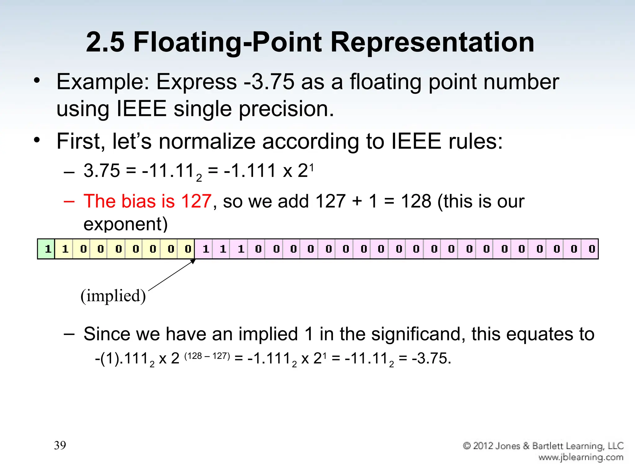
• Example: Express-3.75 as a floating point number
using IEEE single precision.
• First, let’s normalize according to IEEE rules:
– 3.75 = -11.112 = -1.111 x 21
– The bias is 127, so we add 127 + 1 = 128 (this is our
exponent)
– The first 1 in the significand is implied, so we have:
– Since we have an implied 1 in the significand, this equates to
-(1).1112 x 2 (128 – 127)
= -1.1112 x 21
= -11.112 = -3.75.
(implied)
2.5 Floating-Point Representation
40.
40
• Calculations aren’tuseful until their results can
be displayed in a manner that is meaningful to
people.
• We also need to store the results of calculations,
and provide a means for data input.
• Thus, human-understandable characters must be
converted to computer-understandable bit
patterns using some sort of character encoding
scheme.
2.6 Character Codes
41.
41
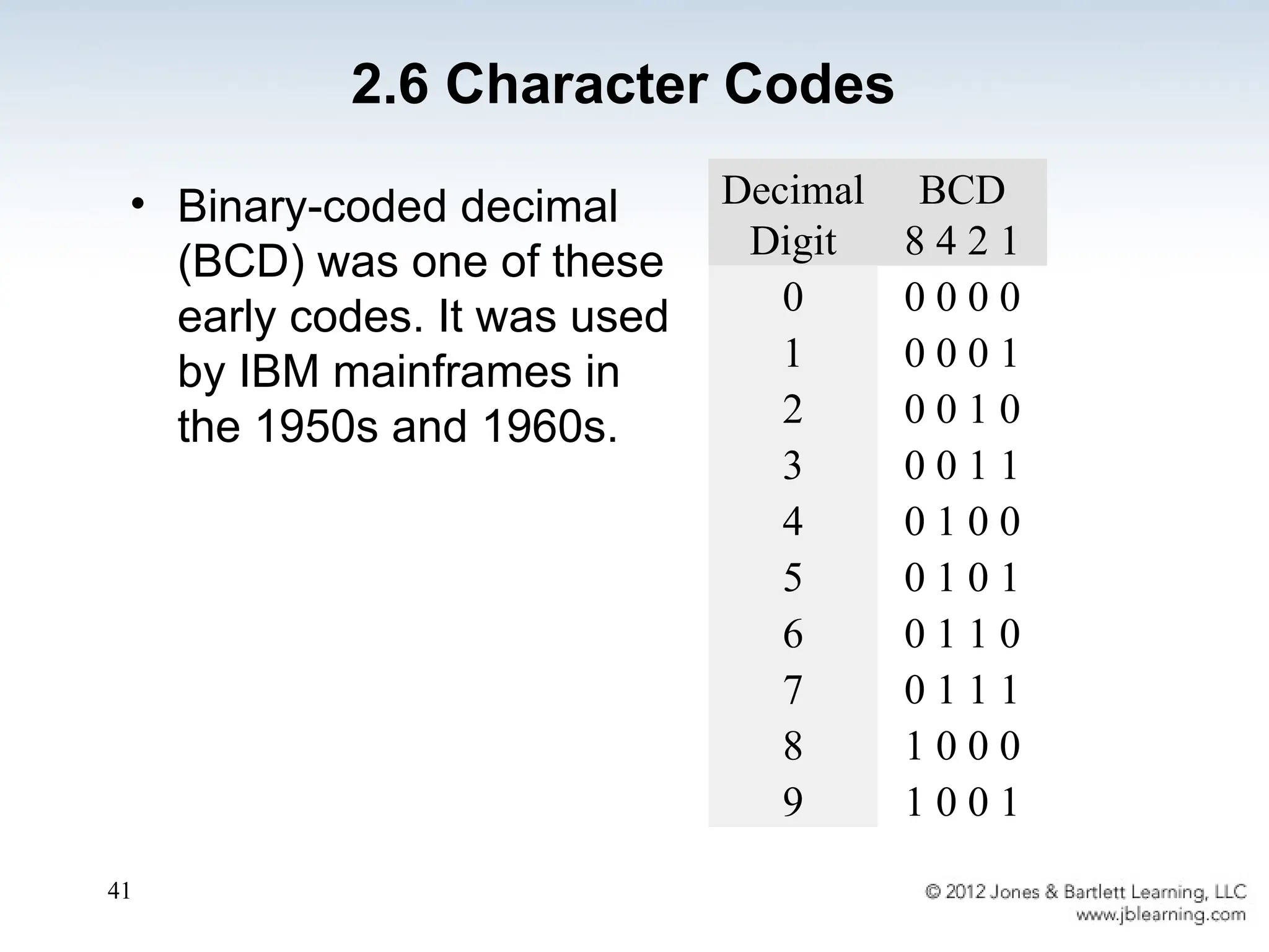
• Binary-coded decimal
(BCD)was one of these
early codes. It was used
by IBM mainframes in
the 1950s and 1960s.
2.6 Character Codes
Decimal
Digit
BCD
8 4 2 1
0 0 0 0 0
1 0 0 0 1
2 0 0 1 0
3 0 0 1 1
4 0 1 0 0
5 0 1 0 1
6 0 1 1 0
7 0 1 1 1
8 1 0 0 0
9 1 0 0 1
42.
42
• In 1964,BCD was extended to an 8-bit code,
Extended Binary-Coded Decimal Interchange
Code (EBCDIC). See textbook Page 89
• EBCDIC was one of the first widely-used
computer codes that supported upper and
lowercase alphabetic characters, in addition to
special characters, such as punctuation and
control characters.
• EBCDIC and BCD are still in use by IBM
mainframes today.
2.6 Character Codes
43.
43
• Other computermanufacturers chose the 7-bit
ASCII (American Standard Code for Information
Interchange) as a replacement for 6-bit codes.
see textbook page 90.
• While BCD and EBCDIC were based upon
punched card codes, ASCII was based upon
telecommunications (Telex) codes.
• Until recently, ASCII was the dominant character
code outside the IBM mainframe world.
2.6 Character Codes
44.
44
• Many oftoday’s systems embrace Unicode, a 16-
bit system that can encode the characters of
every language in the world.
– The Java programming language, and some operating
systems now use Unicode as their default character
code.
• The Unicode codespace is divided into six parts.
The first part is for Western alphabet codes,
including English, Greek, and Russian.
2.6 Character Codes
45.
45
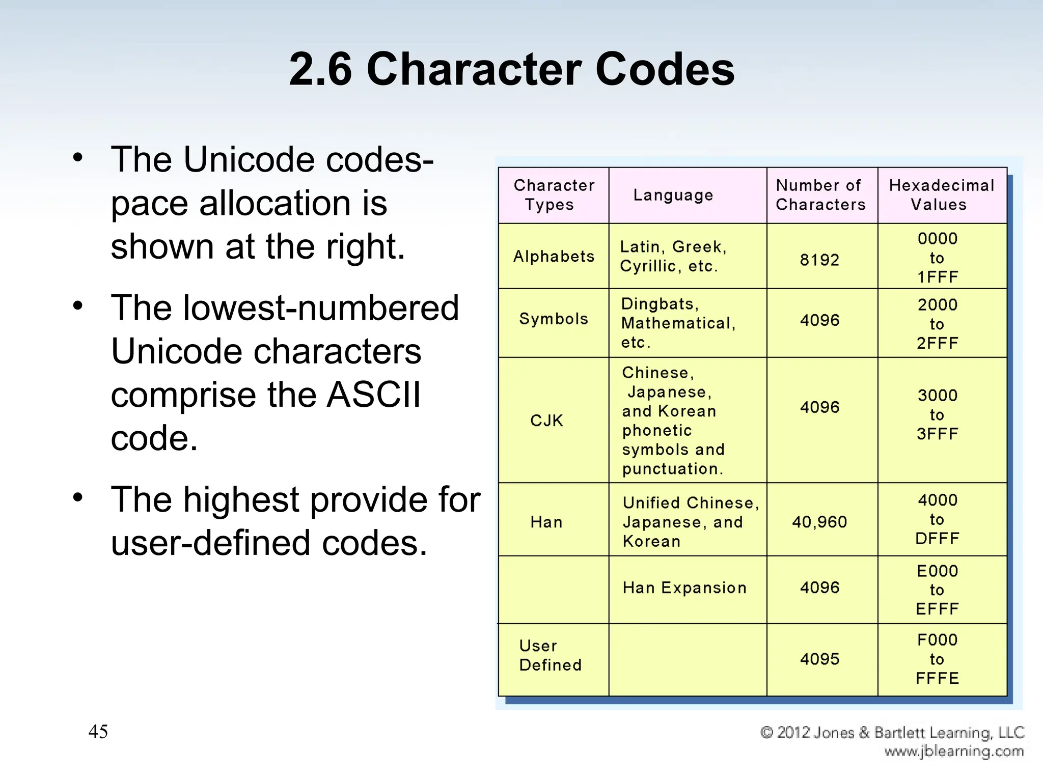
• The Unicodecodes-
pace allocation is
shown at the right.
• The lowest-numbered
Unicode characters
comprise the ASCII
code.
• The highest provide for
user-defined codes.
2.6 Character Codes
46.
46
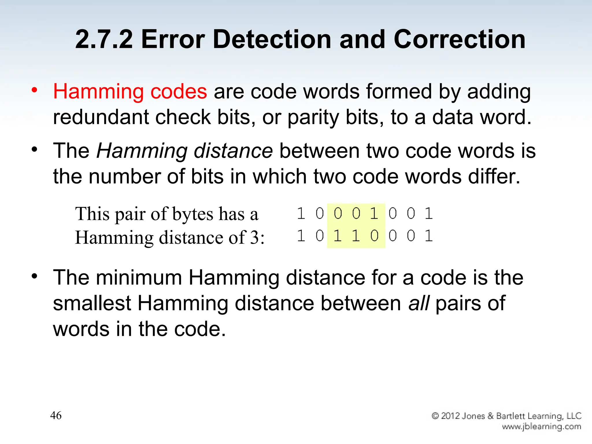
• Hamming codesare code words formed by adding
redundant check bits, or parity bits, to a data word.
• The Hamming distance between two code words is
the number of bits in which two code words differ.
• The minimum Hamming distance for a code is the
smallest Hamming distance between all pairs of
words in the code.
This pair of bytes has a
Hamming distance of 3:
2.7.2 Error Detection and Correction
47.
47
• The minimumHamming distance for a code,
D(min), determines its error detecting and error
correcting capability.
• For any code word, X, to be interpreted as a
different valid code word, Y, at least D(min)
single-bit errors must occur in X.
• Thus, to detect k (or fewer) single-bit errors, the
code must have a Hamming distance of
D(min) = k + 1.
2.7.2 Error Detection and Correction
48.
48
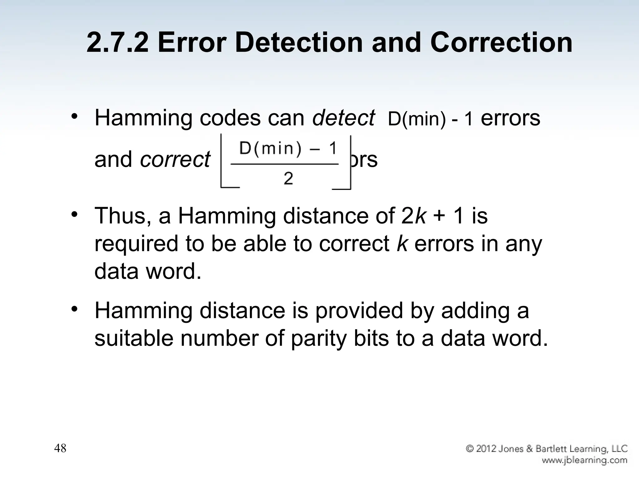
• Hamming codescan detect D(min) - 1 errors
and correct errors
• Thus, a Hamming distance of 2k + 1 is
required to be able to correct k errors in any
data word.
• Hamming distance is provided by adding a
suitable number of parity bits to a data word.
2.7.2 Error Detection and Correction
49.
49
• Suppose wehave a set of n-bit code words
consisting of m data bits and r (redundant) parity
bits.
• Suppose also that we wish to detect and correct one
single bit error only.
• An error could occur in any of the n bits, so each
code word can be associated with n invalid code
words at a Hamming distance of 1.
• Therefore, we have n + 1 bit patterns for each code
word: one valid code word, and n invalid code words
2.7.2 Error Detection and Correction
50.
50
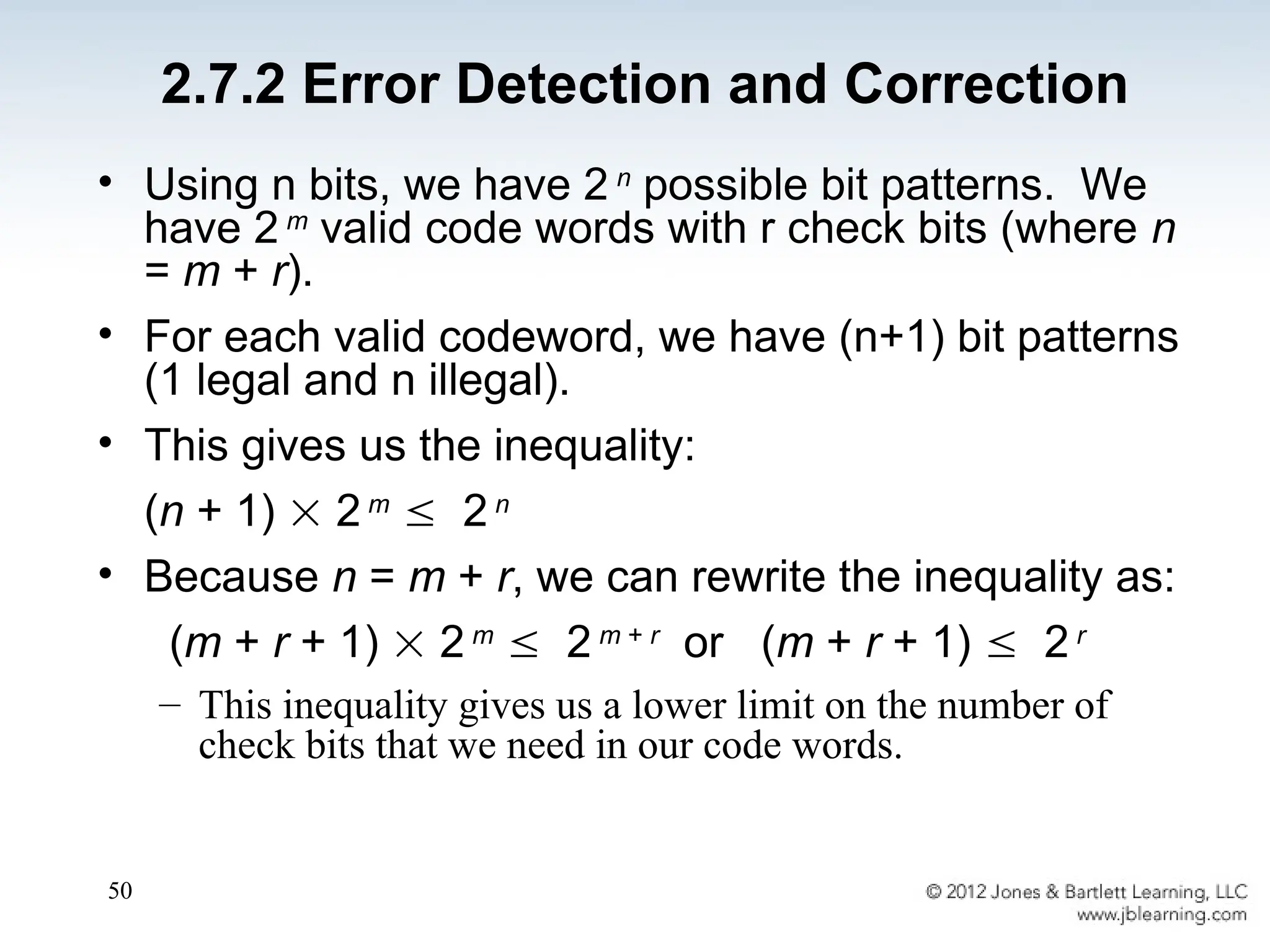
• Using nbits, we have 2 n
possible bit patterns. We
have 2 m
valid code words with r check bits (where n
= m + r).
• For each valid codeword, we have (n+1) bit patterns
(1 legal and n illegal).
• This gives us the inequality:
(n + 1) 2 m
2 n
• Because n = m + r, we can rewrite the inequality as:
(m + r + 1) 2 m
2 m + r
or (m + r + 1) 2 r
– This inequality gives us a lower limit on the number of
check bits that we need in our code words.
2.7.2 Error Detection and Correction
51.
51
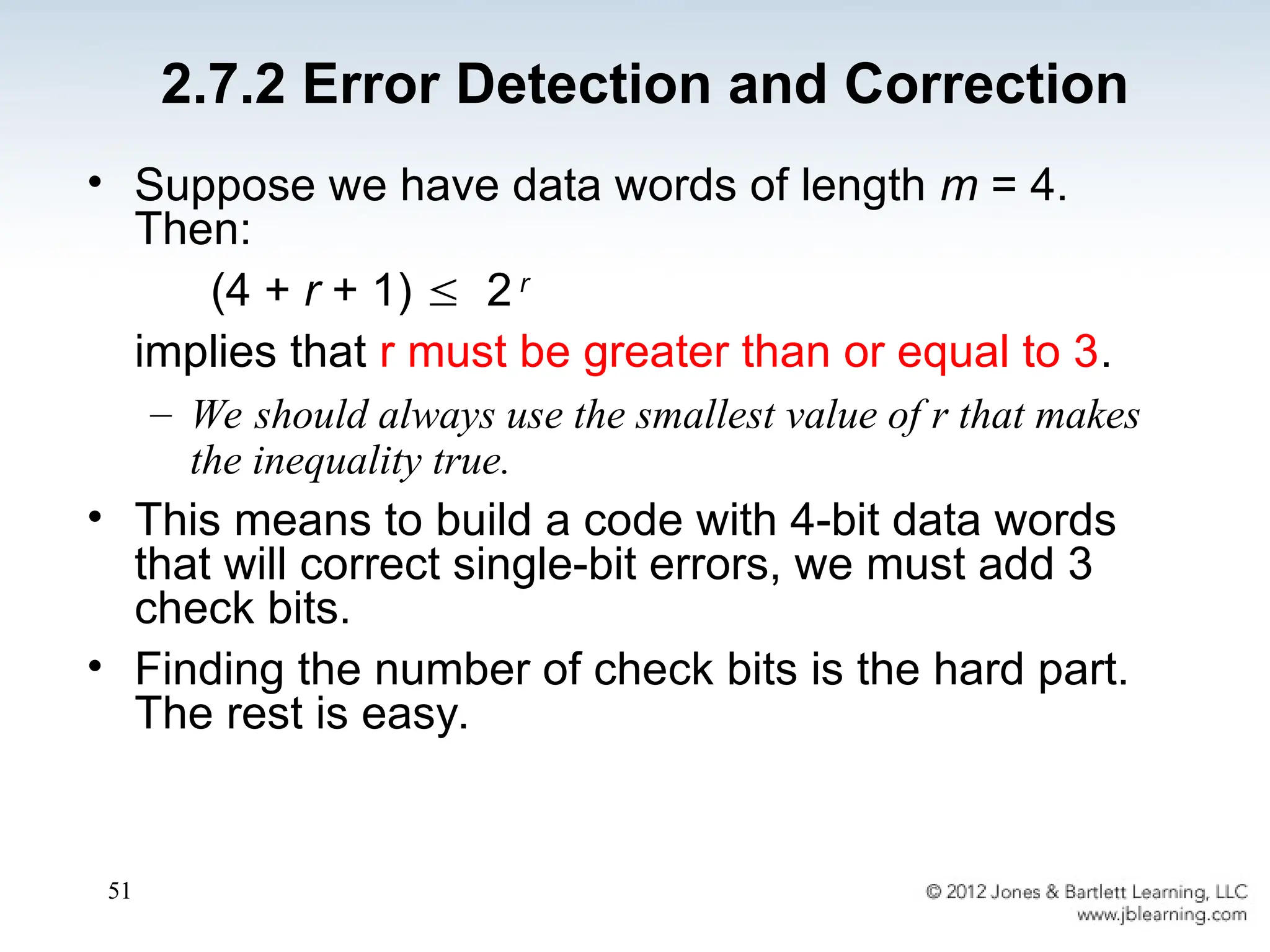
• Suppose wehave data words of length m = 4.
Then:
(4 + r + 1) 2 r
implies that r must be greater than or equal to 3.
– We should always use the smallest value of r that makes
the inequality true.
• This means to build a code with 4-bit data words
that will correct single-bit errors, we must add 3
check bits.
• Finding the number of check bits is the hard part.
The rest is easy.
2.7.2 Error Detection and Correction
52.
52
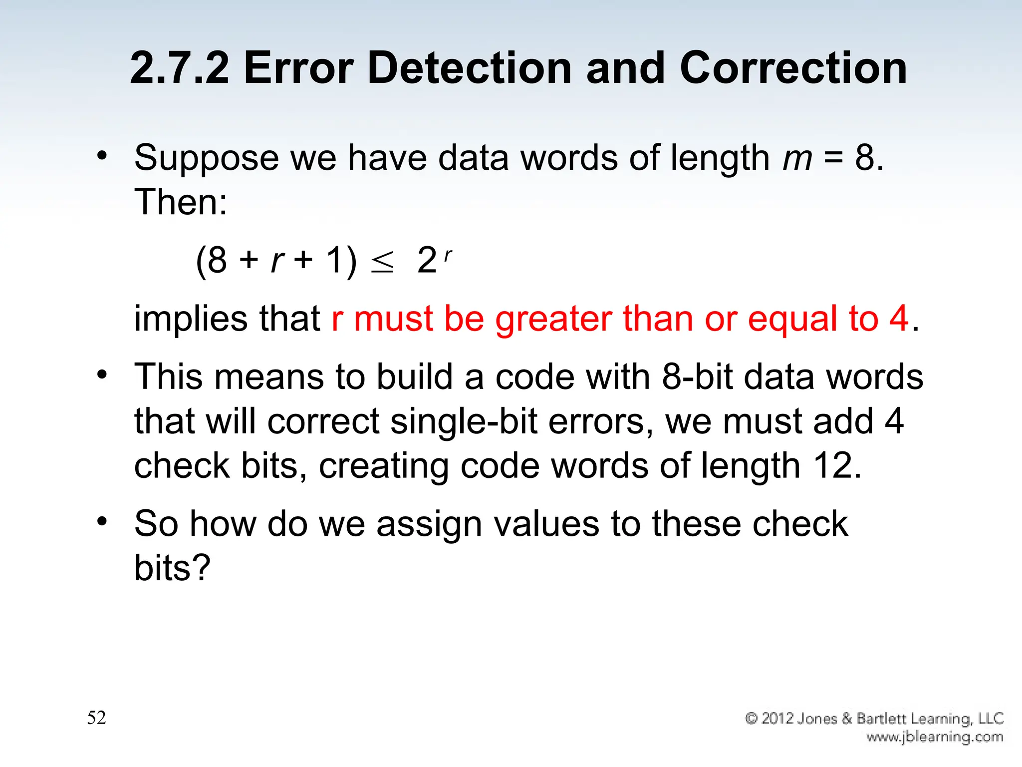
• Suppose wehave data words of length m = 8.
Then:
(8 + r + 1) 2 r
implies that r must be greater than or equal to 4.
• This means to build a code with 8-bit data words
that will correct single-bit errors, we must add 4
check bits, creating code words of length 12.
• So how do we assign values to these check
bits?
2.7.2 Error Detection and Correction
53.
53
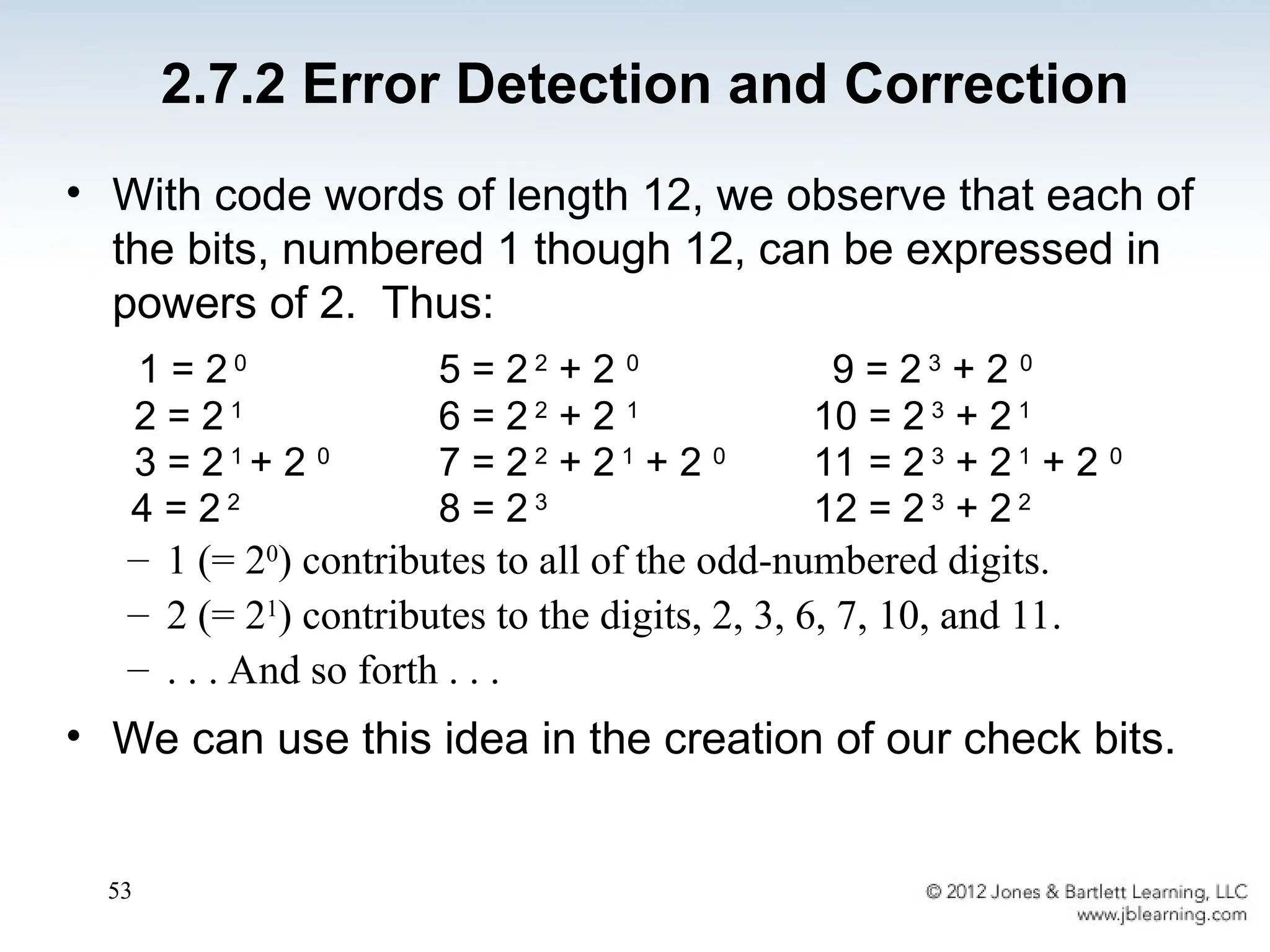
• With codewords of length 12, we observe that each of
the bits, numbered 1 though 12, can be expressed in
powers of 2. Thus:
1 = 2 0
5 = 2 2
+ 2 0
9 = 2 3
+ 2 0
2 = 2 1
6 = 2 2
+ 2 1
10 = 2 3
+ 2 1
3 = 2 1
+ 2 0
7 = 2 2
+ 2 1
+ 2 0
11 = 2 3
+ 2 1
+ 2 0
4 = 2 2
8 = 2 3
12 = 2 3
+ 2 2
– 1 (= 20
) contributes to all of the odd-numbered digits.
– 2 (= 21
) contributes to the digits, 2, 3, 6, 7, 10, and 11.
– . . . And so forth . . .
• We can use this idea in the creation of our check bits.
2.7.2 Error Detection and Correction
54.
54
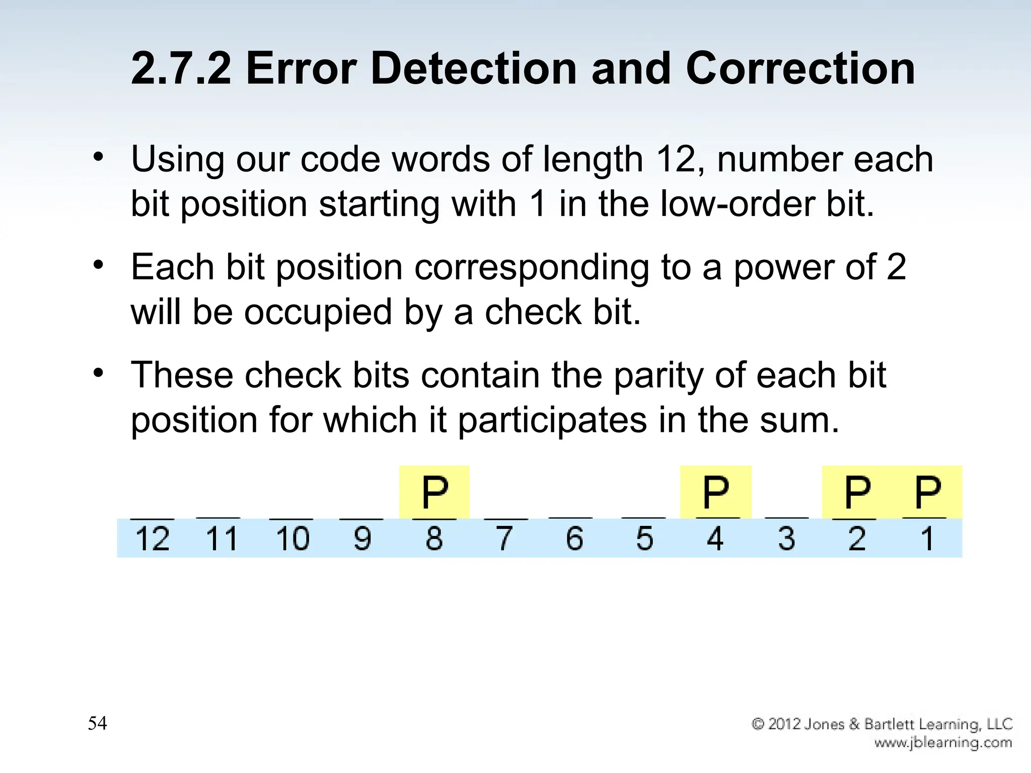
• Using ourcode words of length 12, number each
bit position starting with 1 in the low-order bit.
• Each bit position corresponding to a power of 2
will be occupied by a check bit.
• These check bits contain the parity of each bit
position for which it participates in the sum.
2.7.2 Error Detection and Correction
55.
55
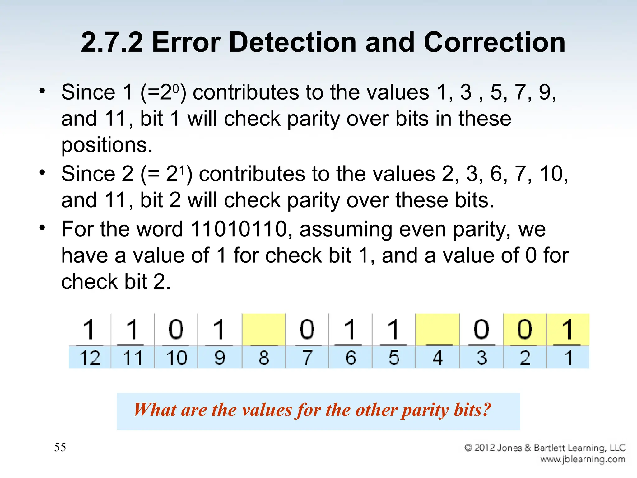
• Since 1(=20
) contributes to the values 1, 3 , 5, 7, 9,
and 11, bit 1 will check parity over bits in these
positions.
• Since 2 (= 21
) contributes to the values 2, 3, 6, 7, 10,
and 11, bit 2 will check parity over these bits.
• For the word 11010110, assuming even parity, we
have a value of 1 for check bit 1, and a value of 0 for
check bit 2.
What are the values for the other parity bits?
2.7.2 Error Detection and Correction
56.
56
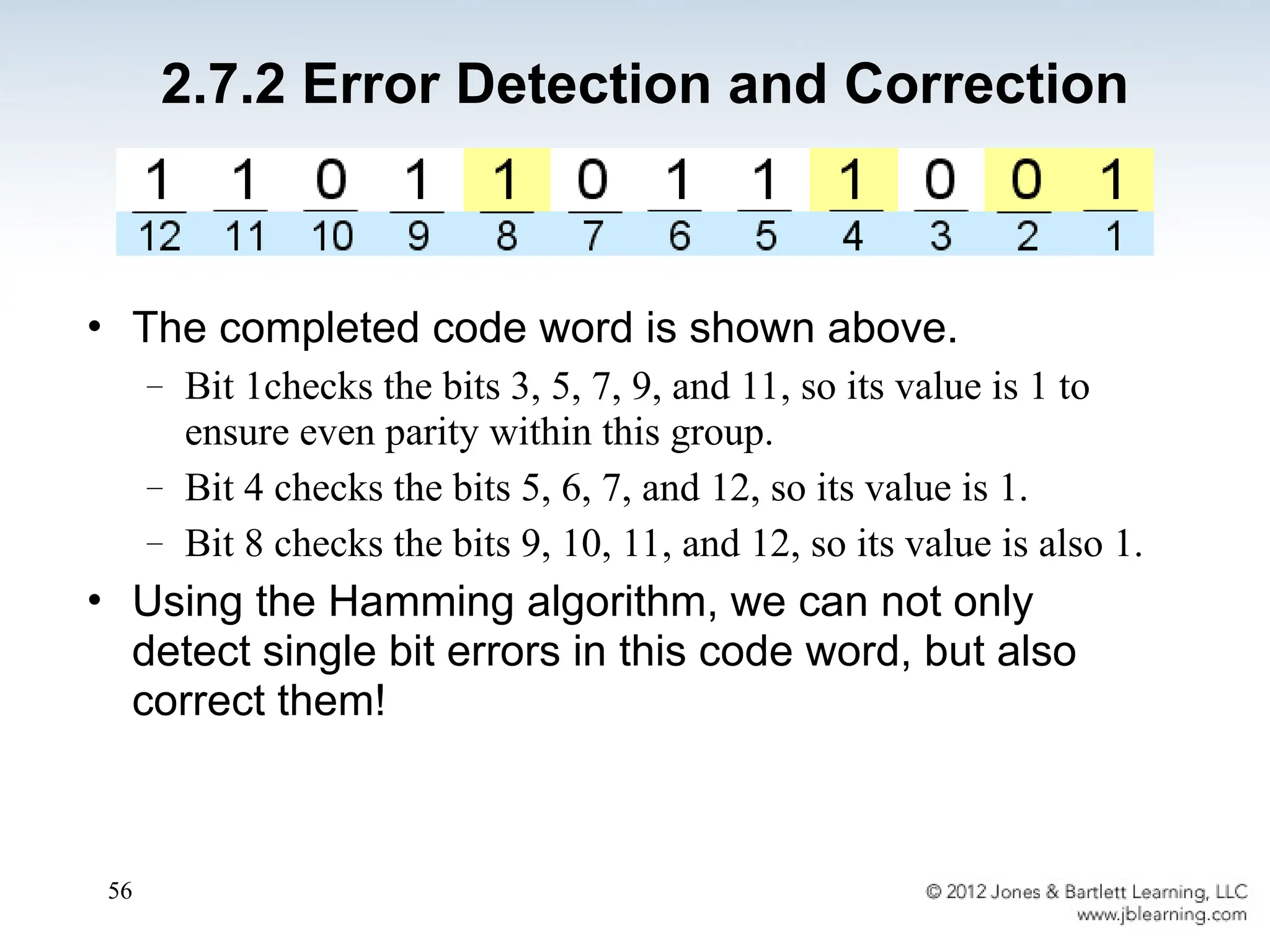
• The completedcode word is shown above.
– Bit 1checks the bits 3, 5, 7, 9, and 11, so its value is 1 to
ensure even parity within this group.
– Bit 4 checks the bits 5, 6, 7, and 12, so its value is 1.
– Bit 8 checks the bits 9, 10, 11, and 12, so its value is also 1.
• Using the Hamming algorithm, we can not only
detect single bit errors in this code word, but also
correct them!
2.7.2 Error Detection and Correction
57.
57
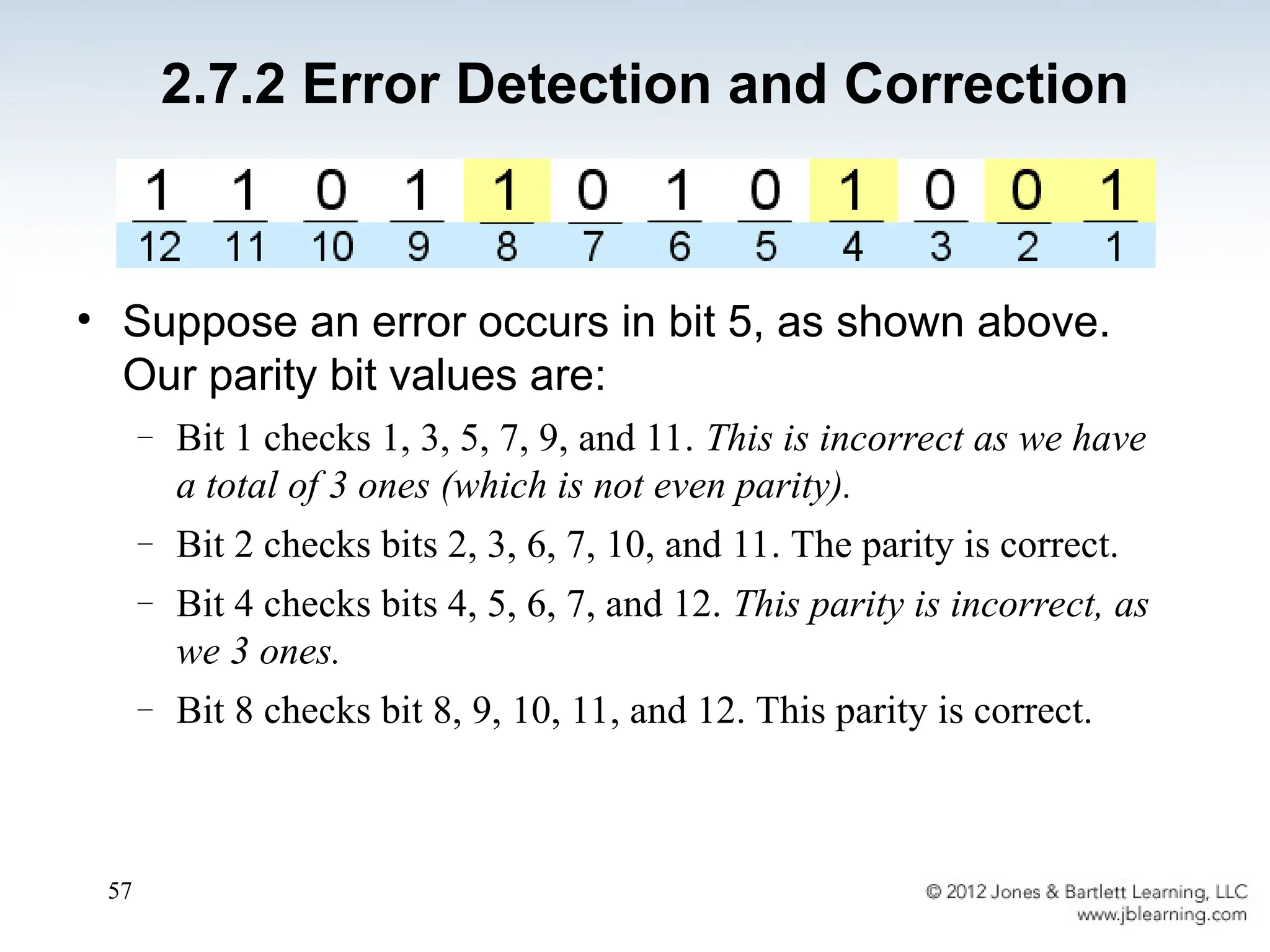
• Suppose anerror occurs in bit 5, as shown above.
Our parity bit values are:
– Bit 1 checks 1, 3, 5, 7, 9, and 11. This is incorrect as we have
a total of 3 ones (which is not even parity).
– Bit 2 checks bits 2, 3, 6, 7, 10, and 11. The parity is correct.
– Bit 4 checks bits 4, 5, 6, 7, and 12. This parity is incorrect, as
we 3 ones.
– Bit 8 checks bit 8, 9, 10, 11, and 12. This parity is correct.
2.7.2 Error Detection and Correction
58.
58
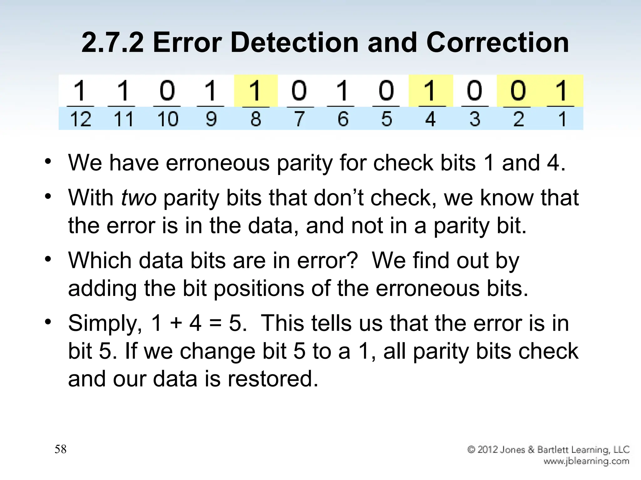
• We haveerroneous parity for check bits 1 and 4.
• With two parity bits that don’t check, we know that
the error is in the data, and not in a parity bit.
• Which data bits are in error? We find out by
adding the bit positions of the erroneous bits.
• Simply, 1 + 4 = 5. This tells us that the error is in
bit 5. If we change bit 5 to a 1, all parity bits check
and our data is restored.
2.7.2 Error Detection and Correction
59.
59
• Computers storedata in the form of bits, bytes,
and words using the binary numbering system.
• Hexadecimal numbers are formed using four-bit
groups called nibbles.
• Signed integers can be stored in one’s
complement, two’s complement, or signed
magnitude representation.
• Floating-point numbers are usually coded using
the IEEE 754 floating-point standard.
Chapter 2 Conclusion
60.
60
• Floating-point operationsare not necessarily
commutative or distributive.
• Character data is stored using ASCII, EBCDIC,
or Unicode.
• Error detecting and correcting codes are
necessary because we can expect no
transmission or storage medium to be perfect.
• CRC, Reed-Solomon, and Hamming codes are
three important error control codes.
Chapter 2 Conclusion