This document discusses various topics related to the physical layer of computer networks including:
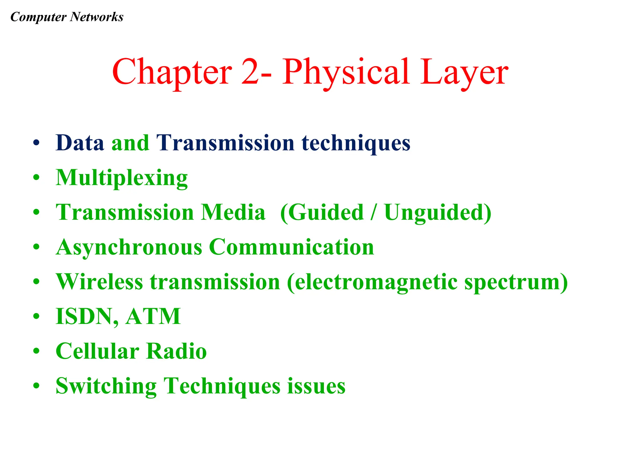
- Data transmission techniques such as multiplexing, different transmission media, asynchronous communication, and wireless transmission.
- Network technologies like ISDN, ATM, and cellular radio.
- Switching techniques and their related issues.
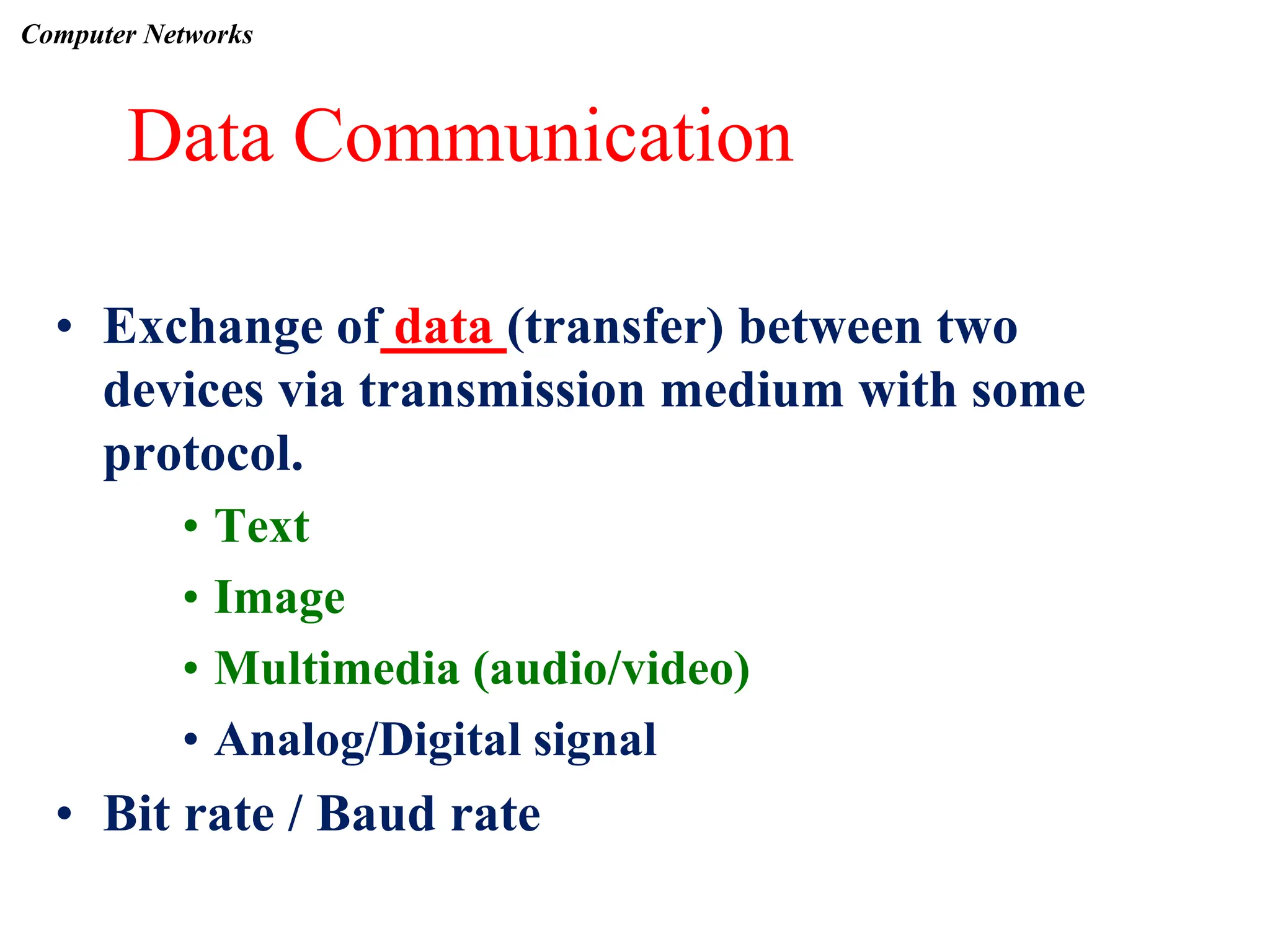
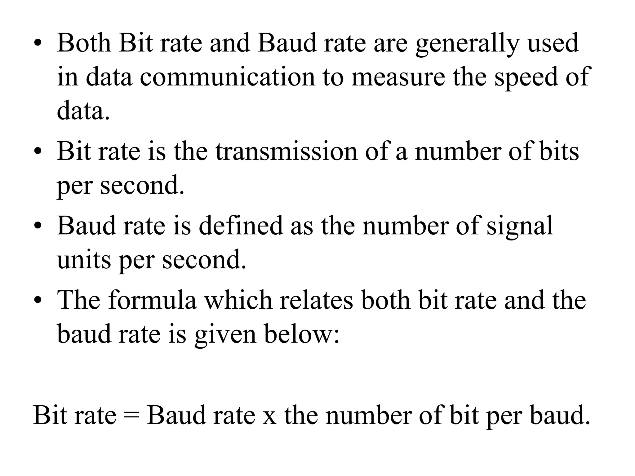
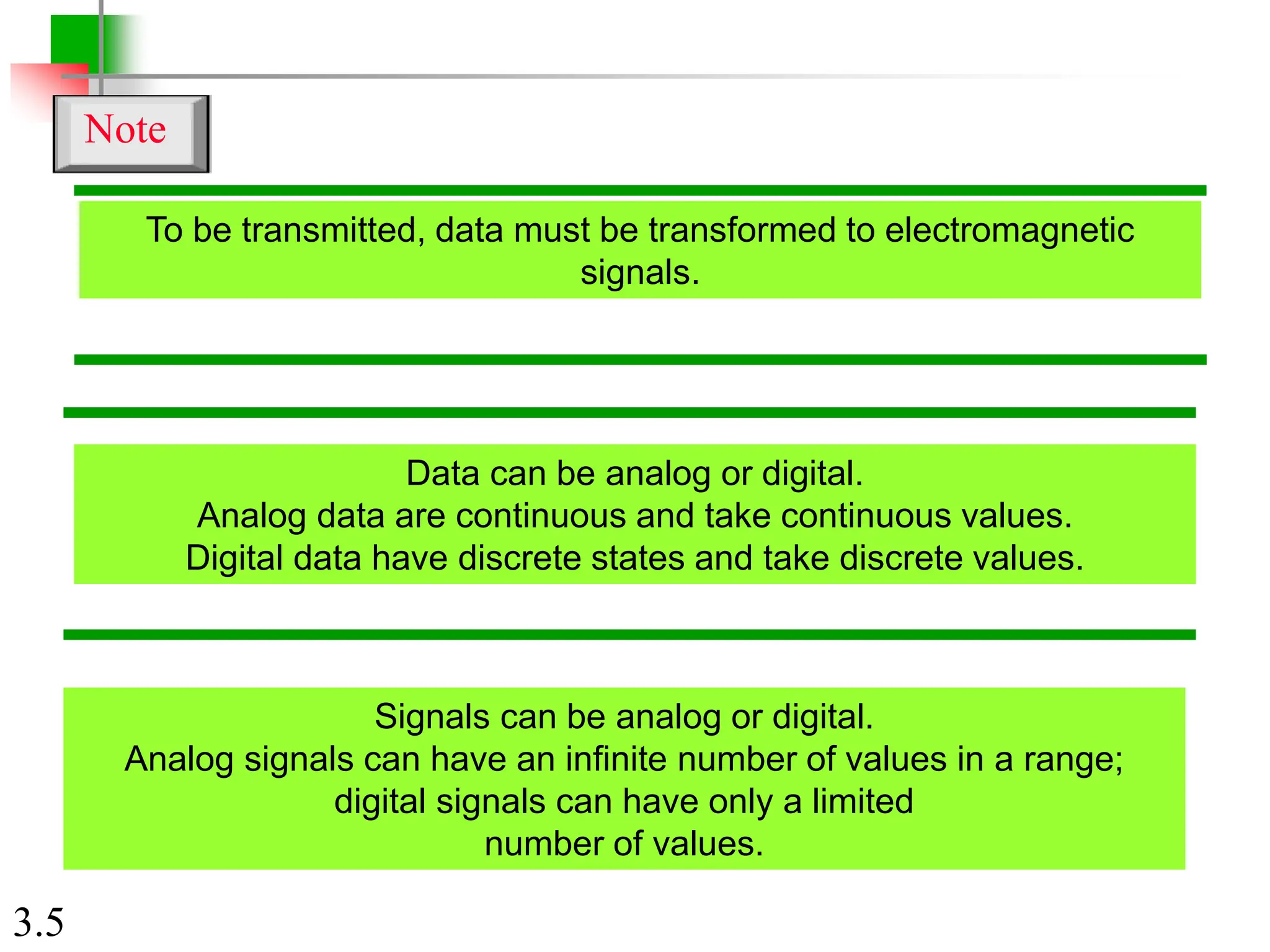
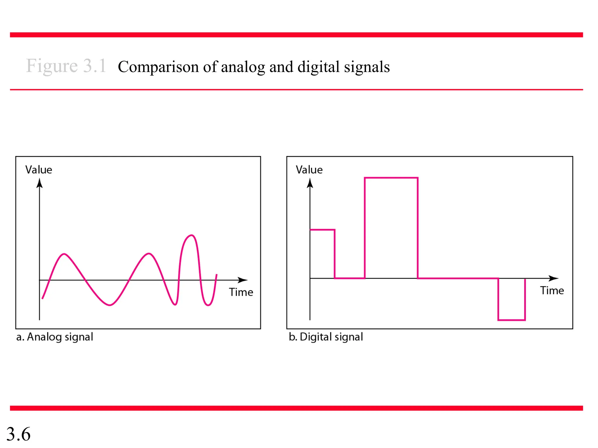
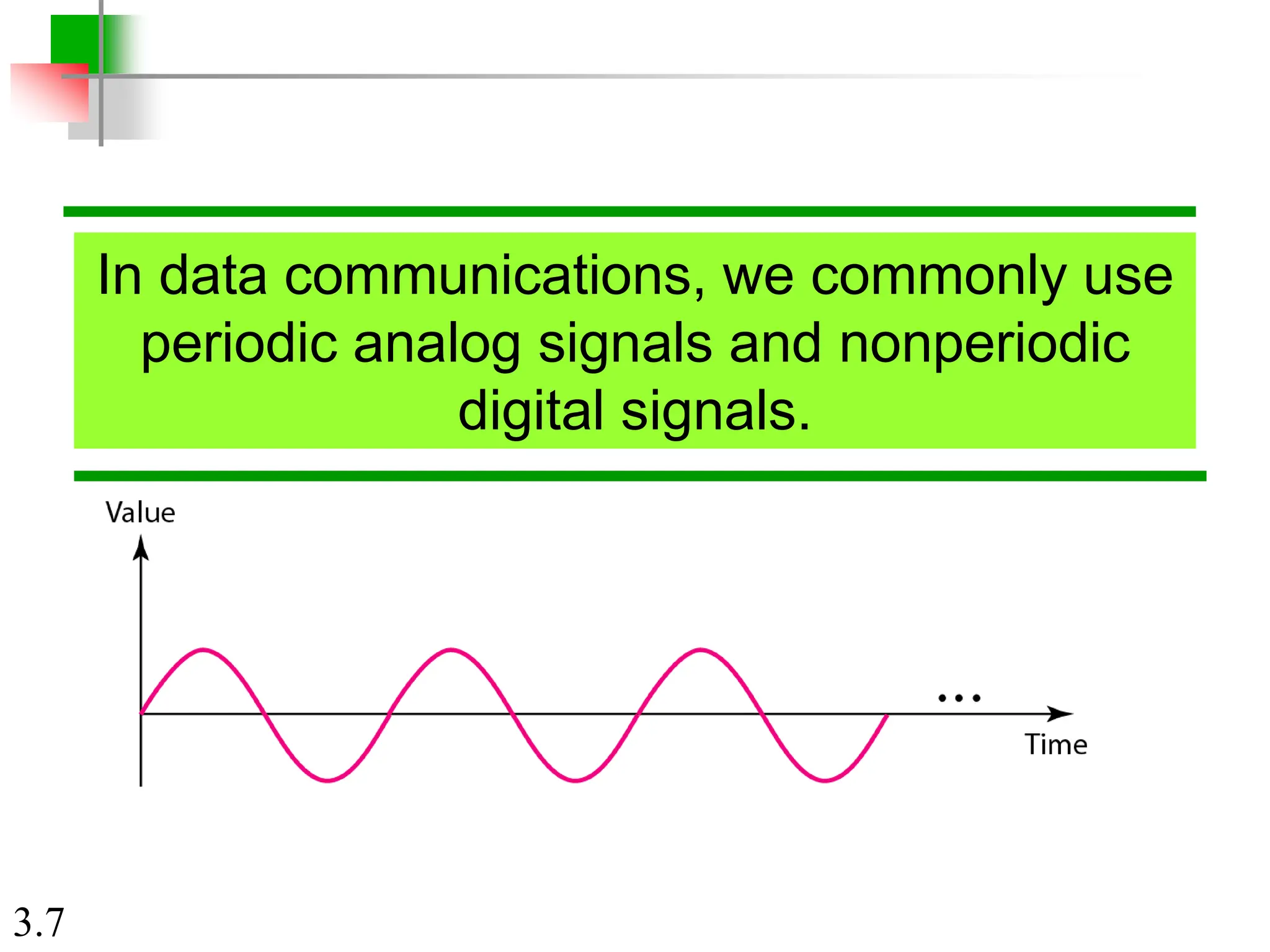
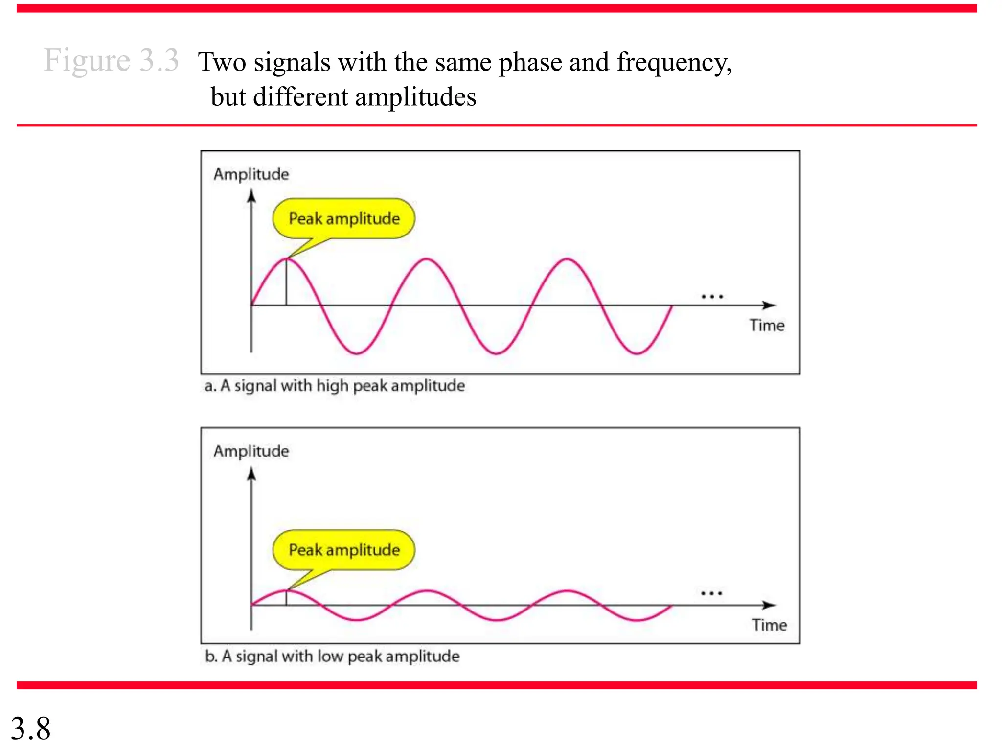
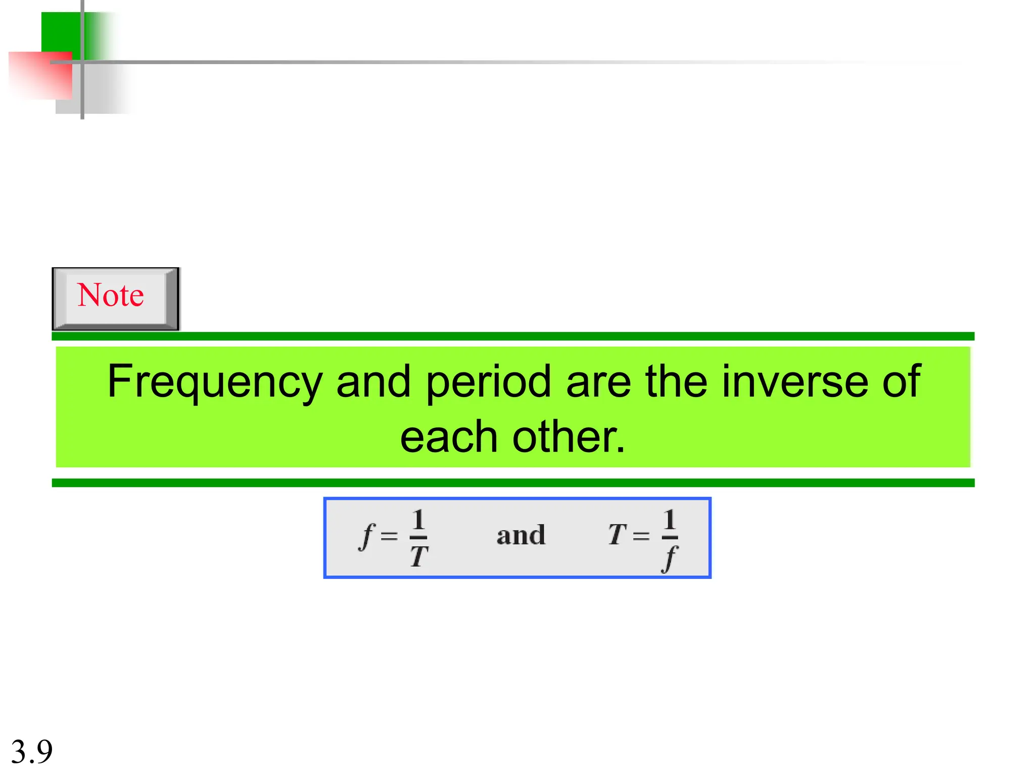
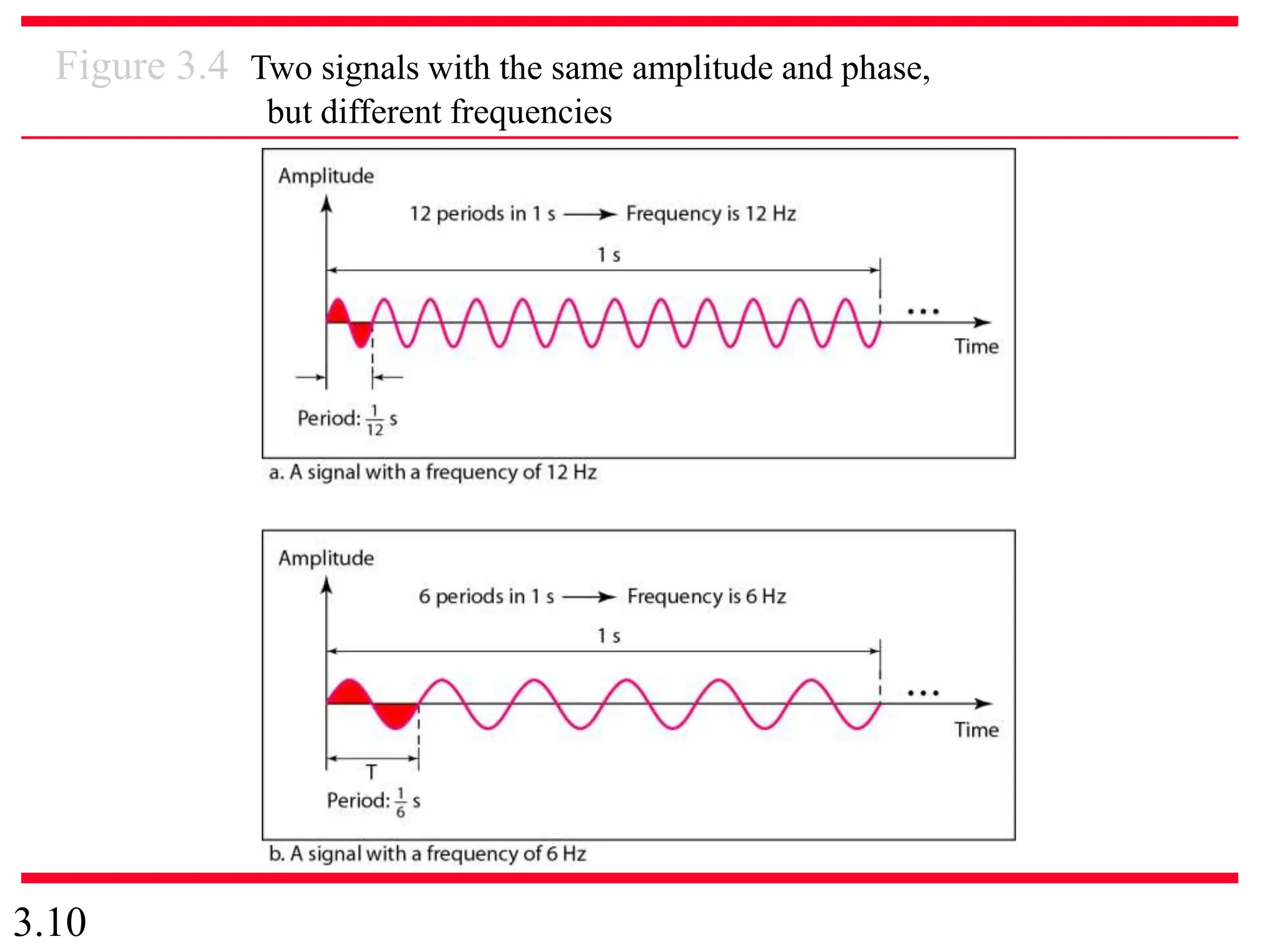
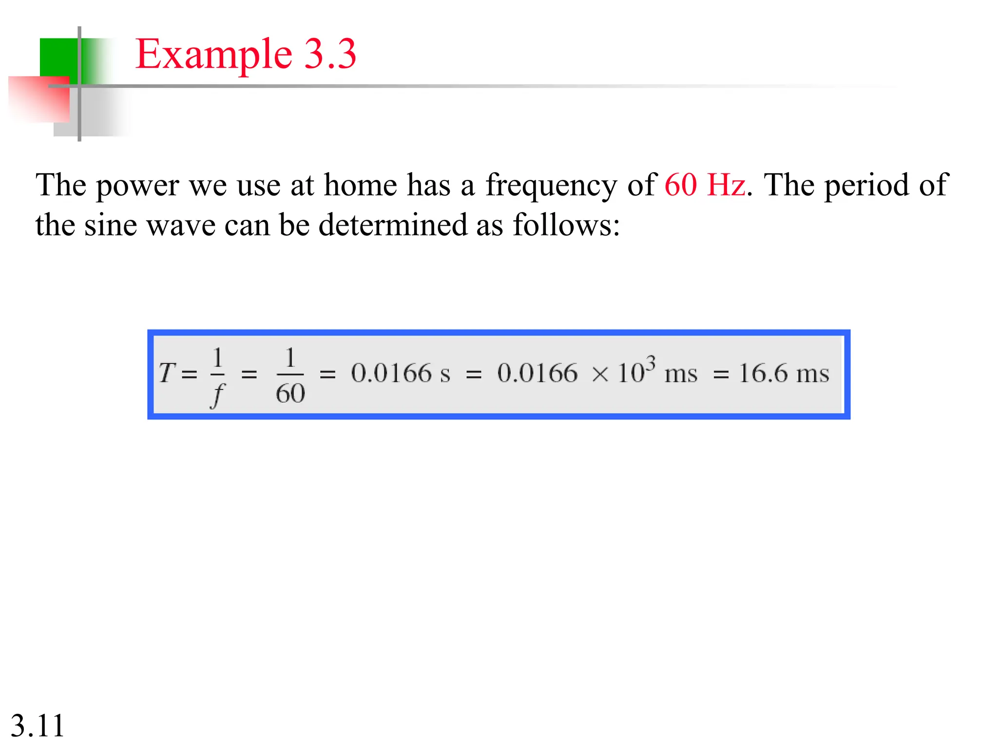
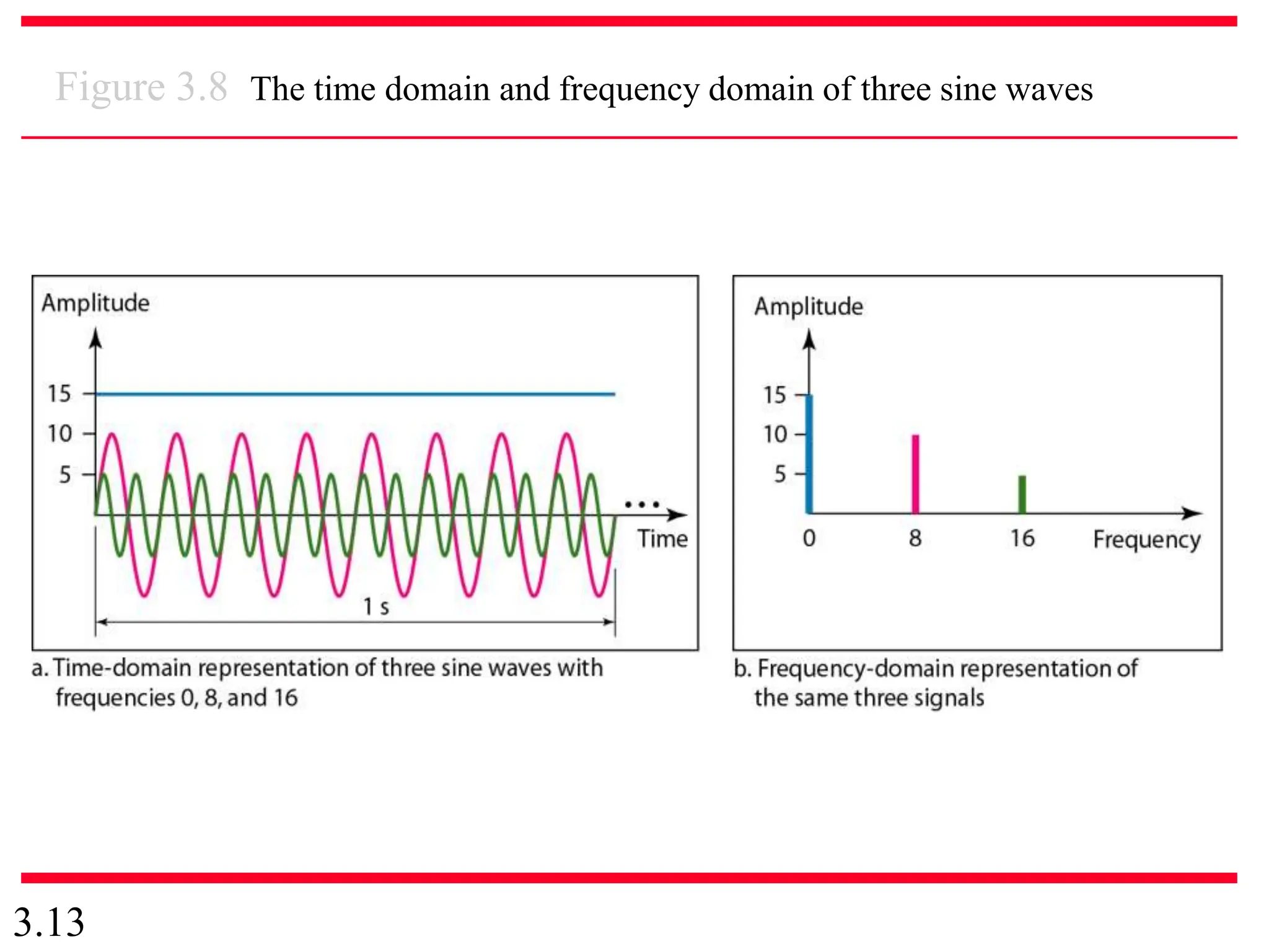
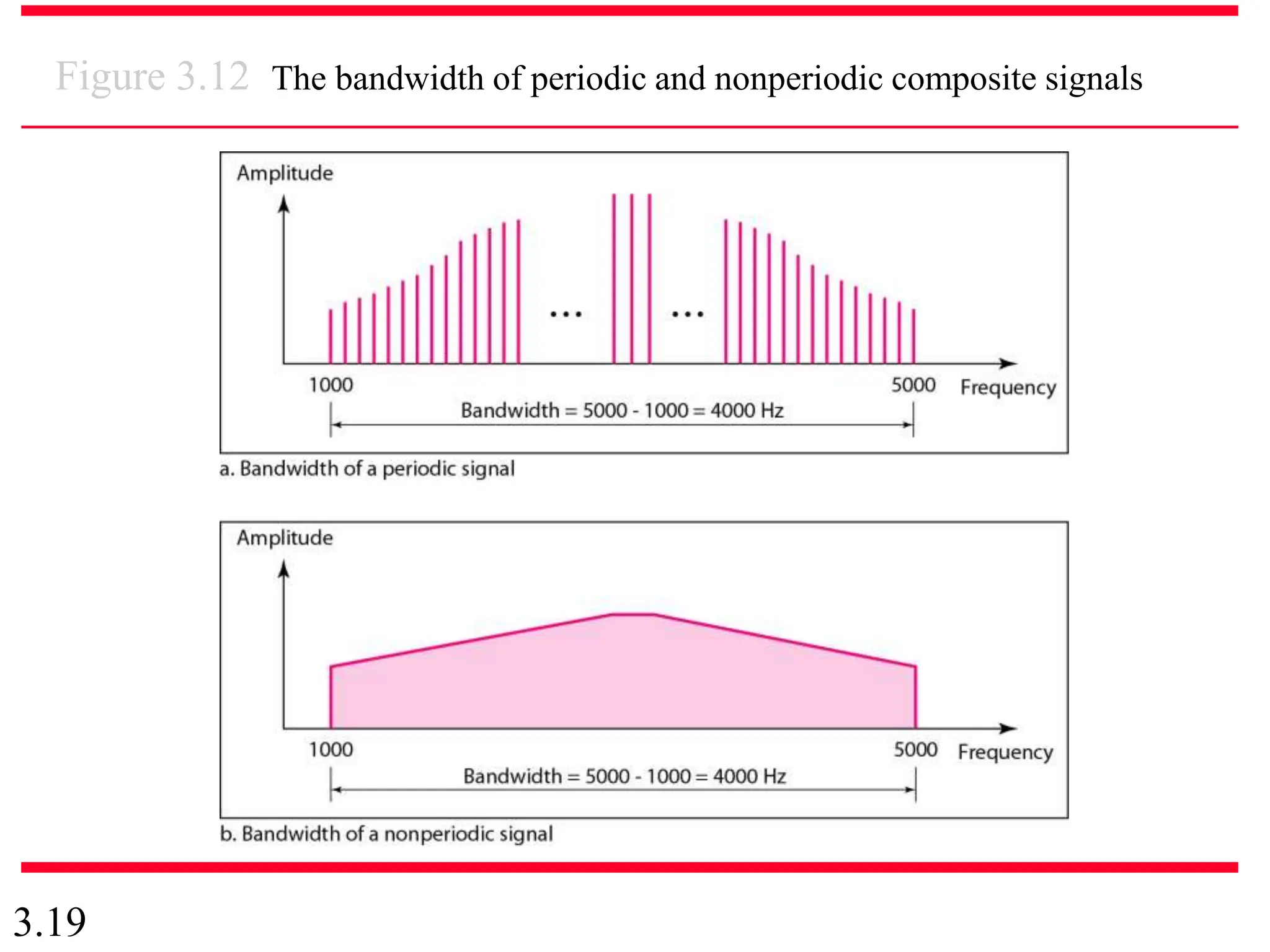
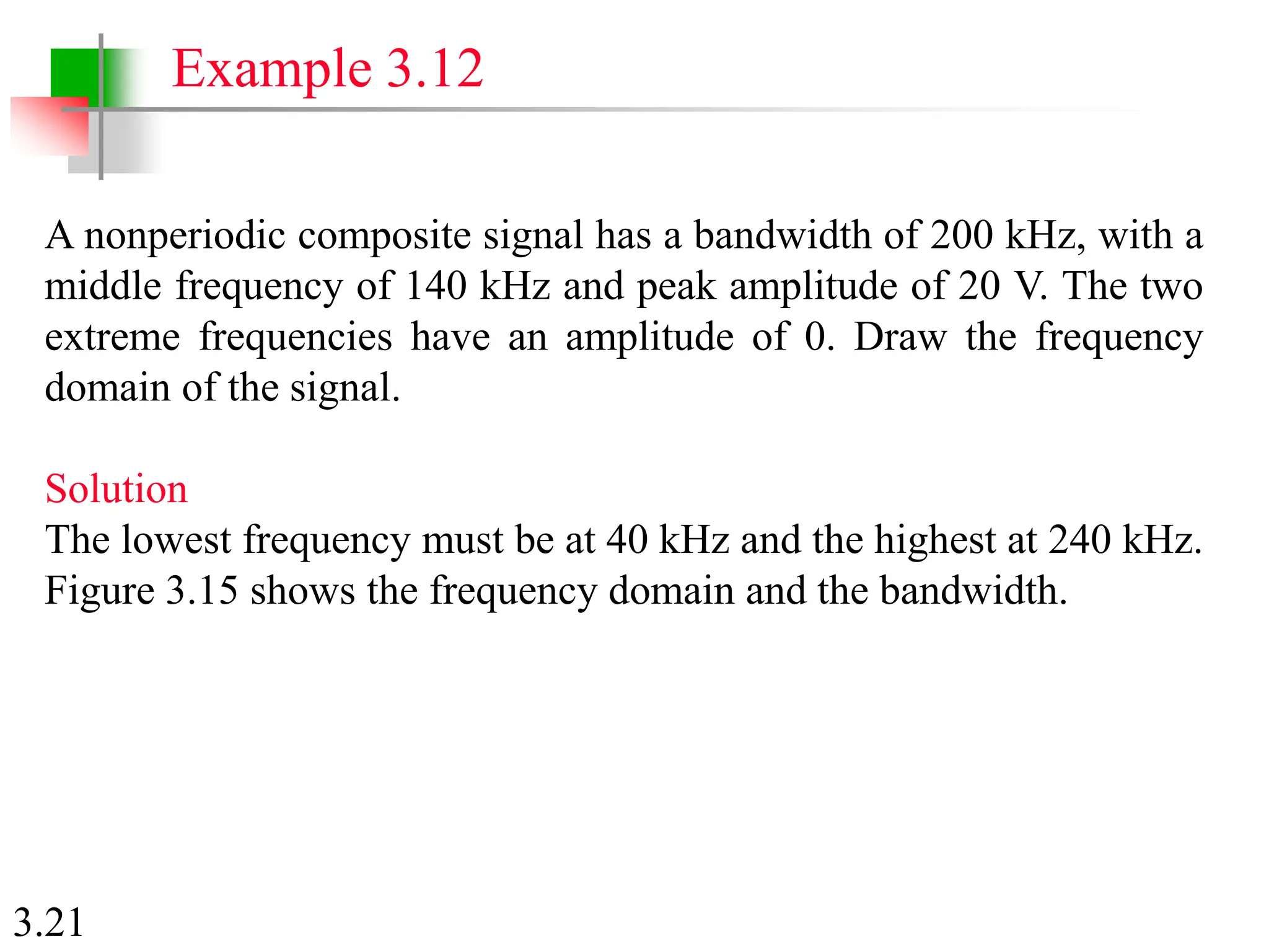
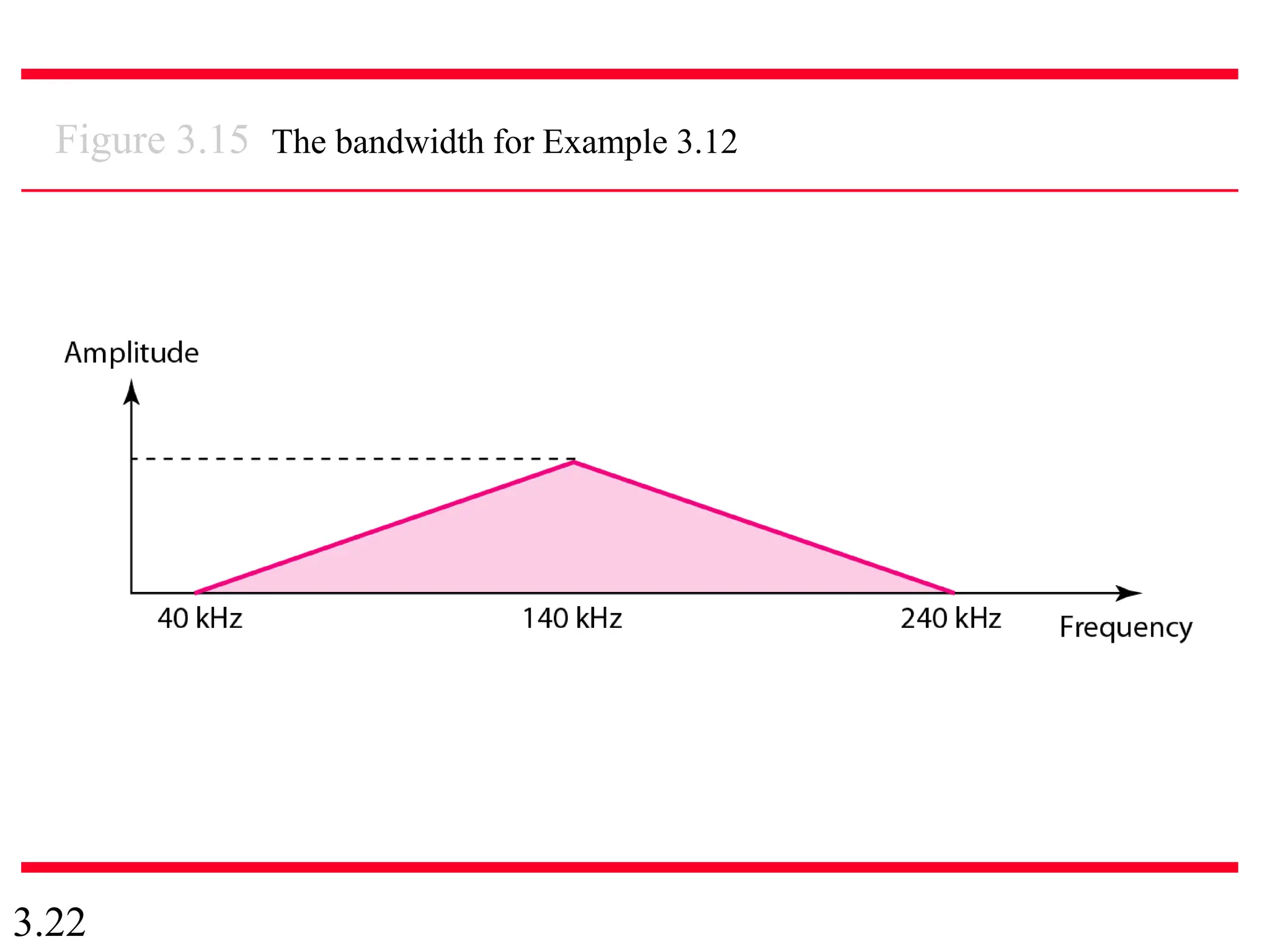
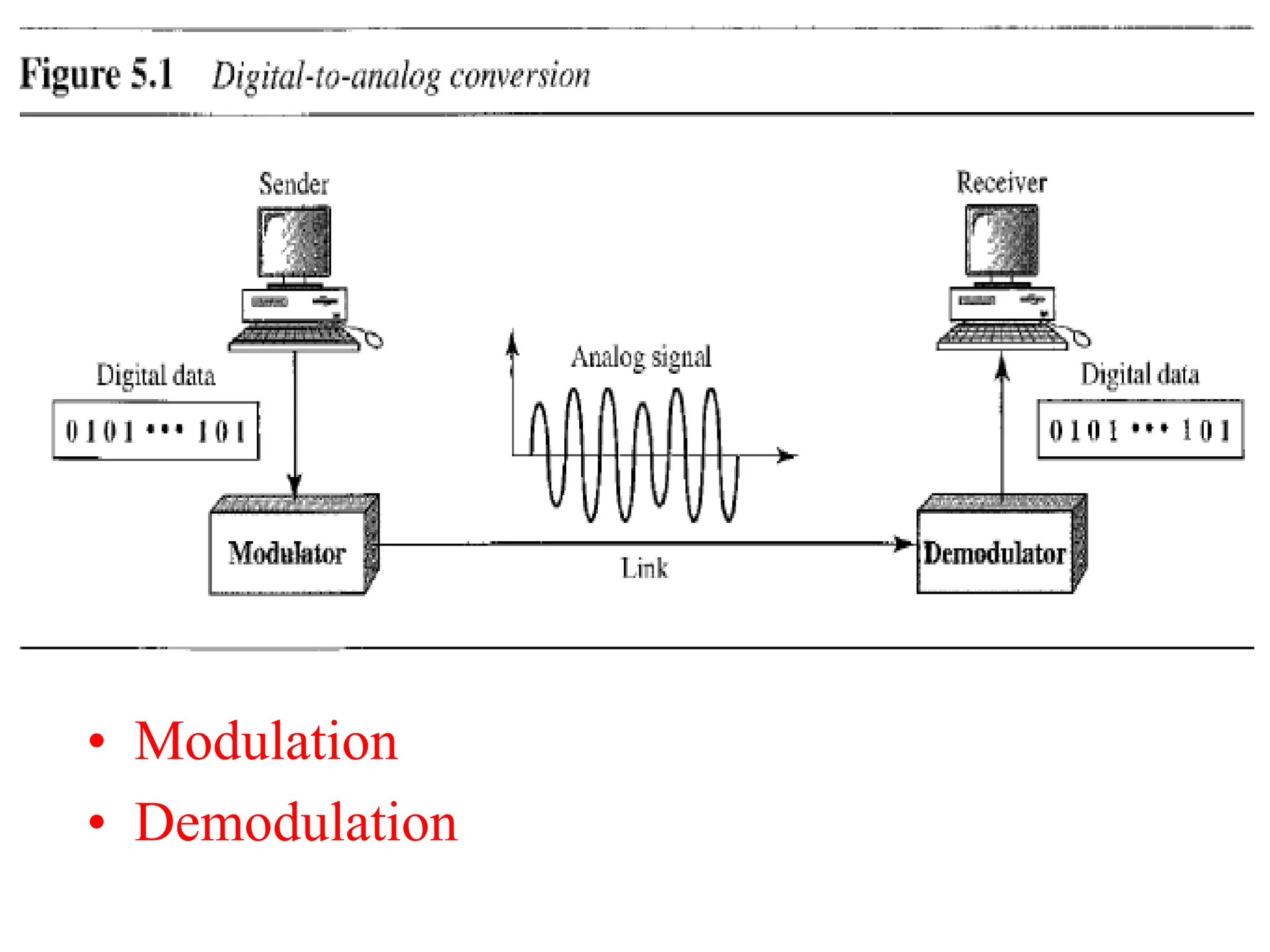
- Analog and digital signals, bit rates, baud rates, and the relationship between them.
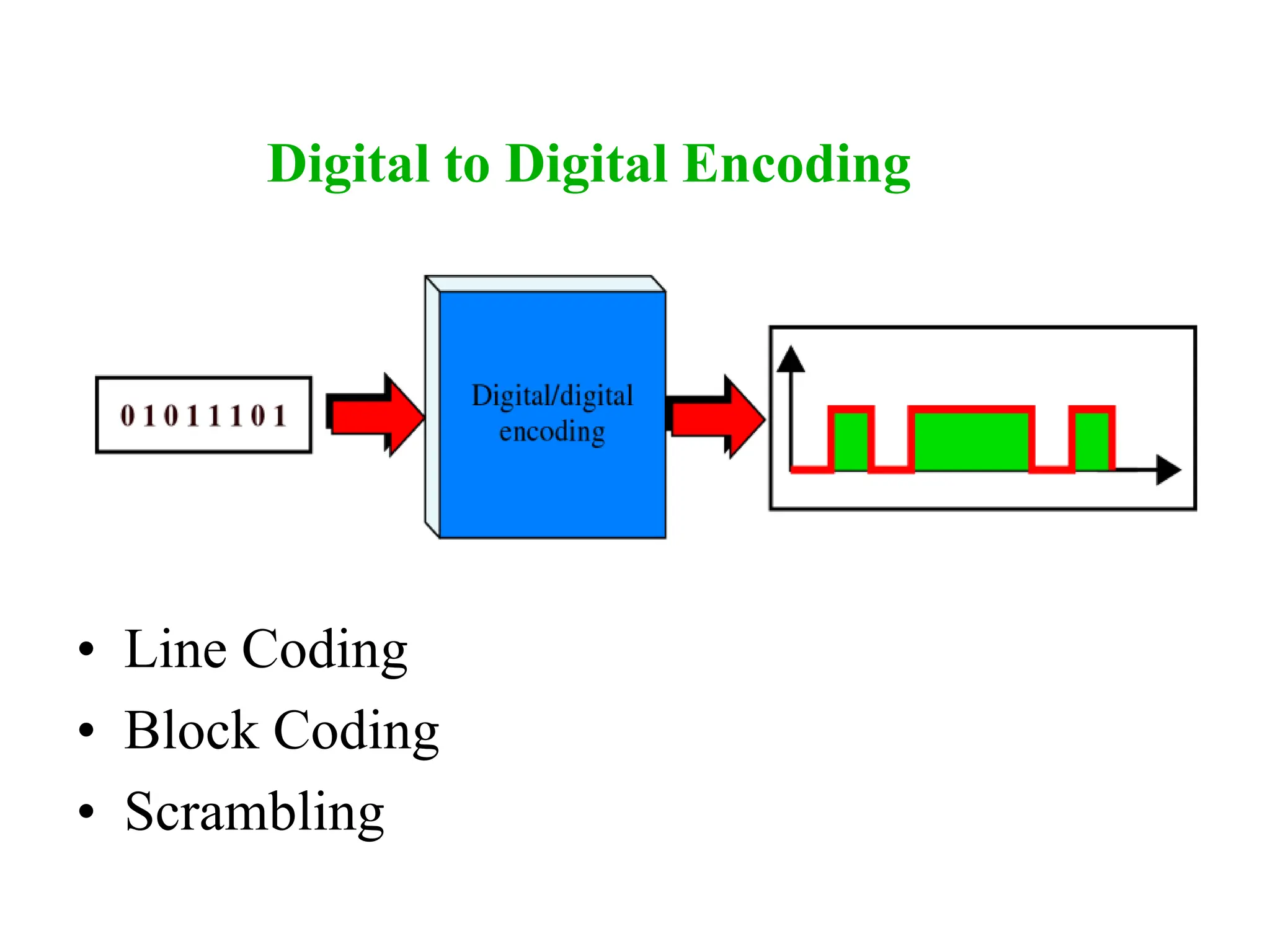
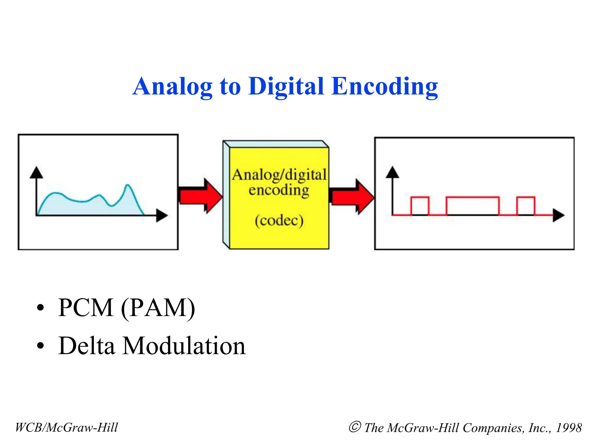
- Encoding schemes for converting between analog and digital domains.
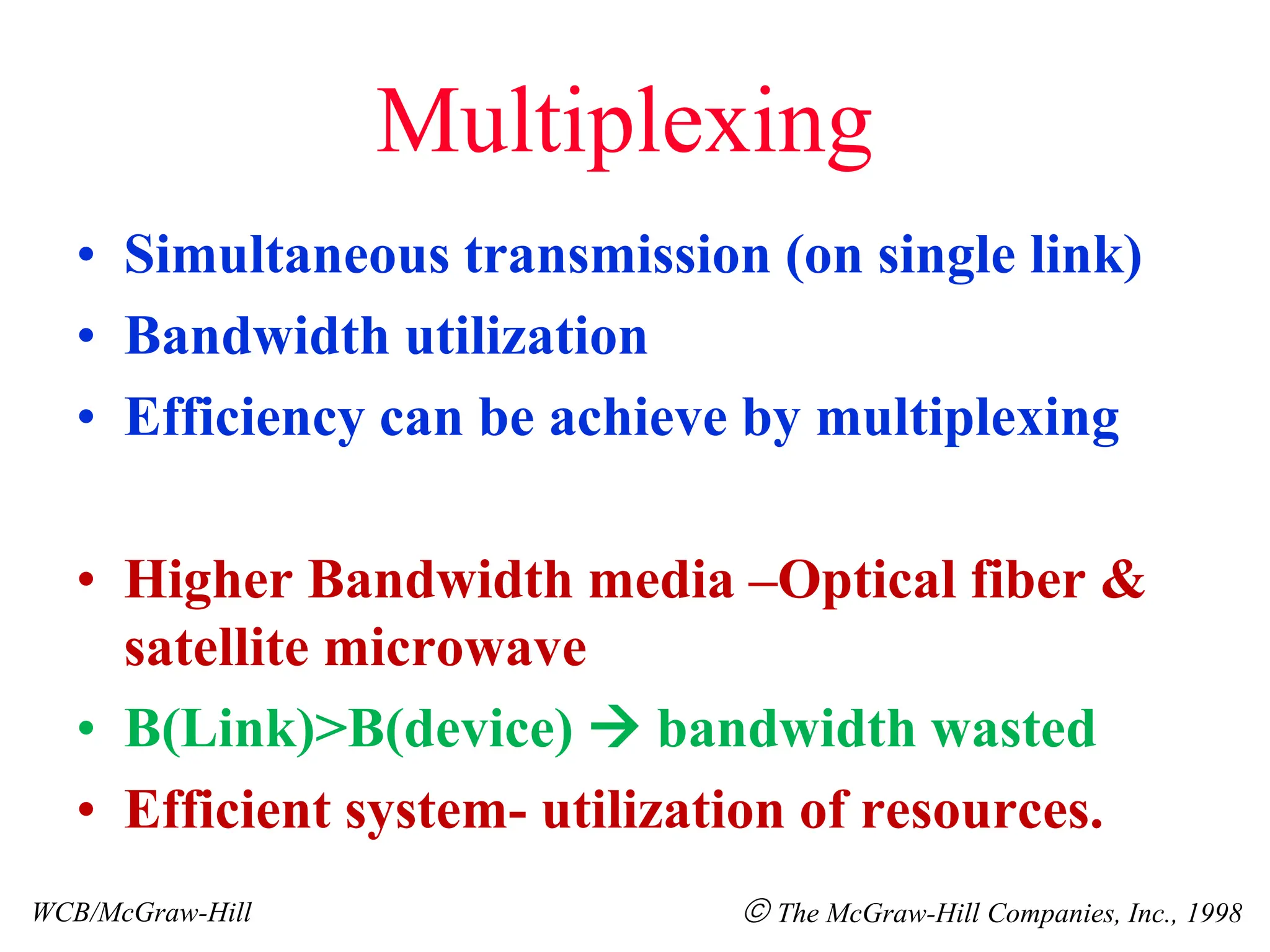
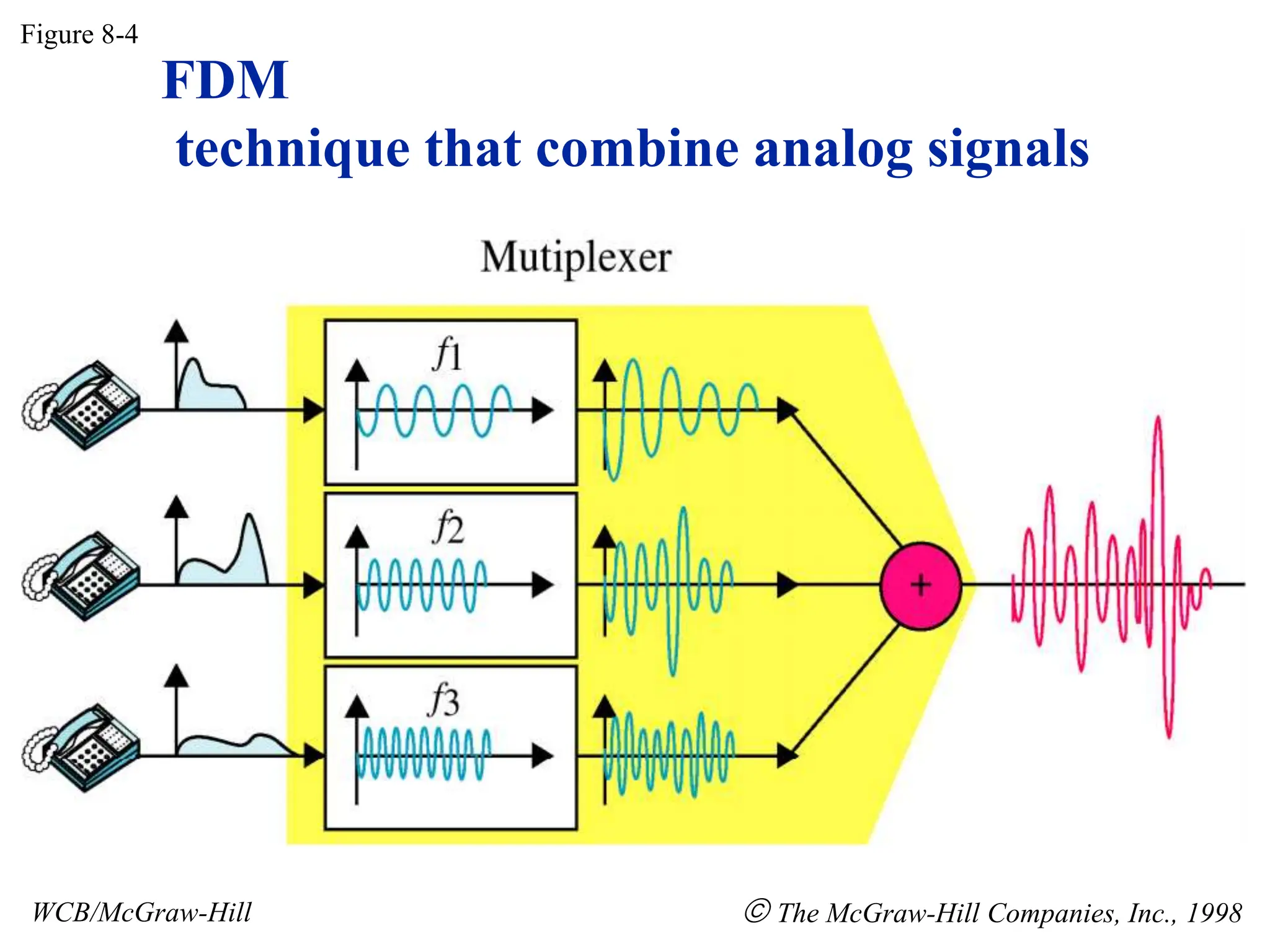
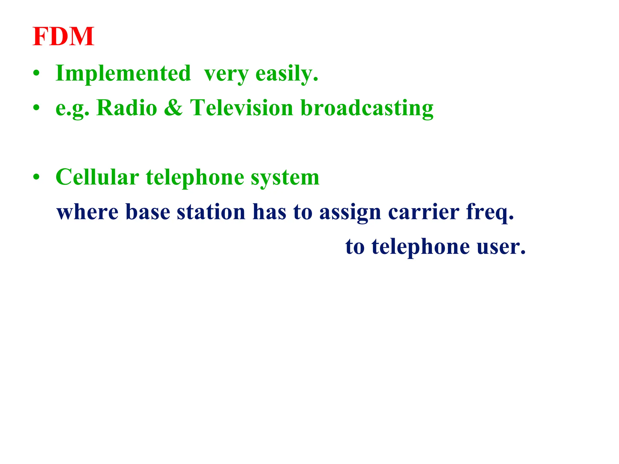
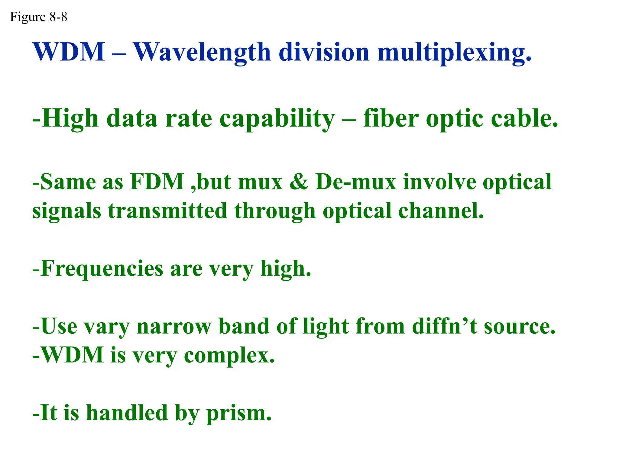
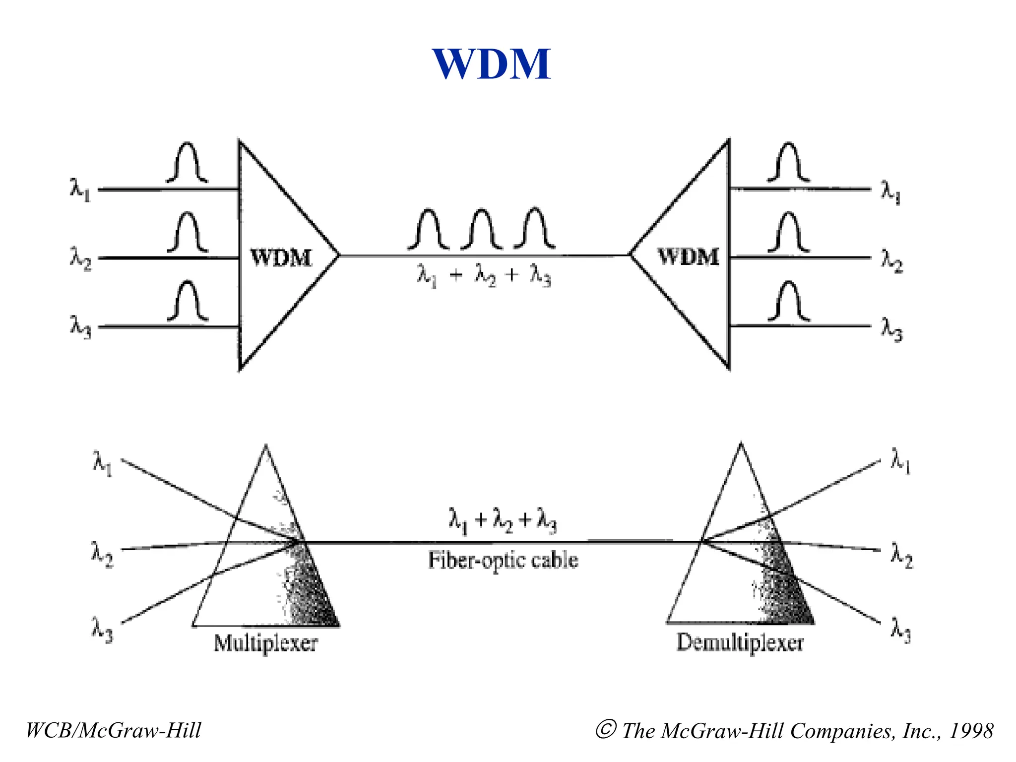
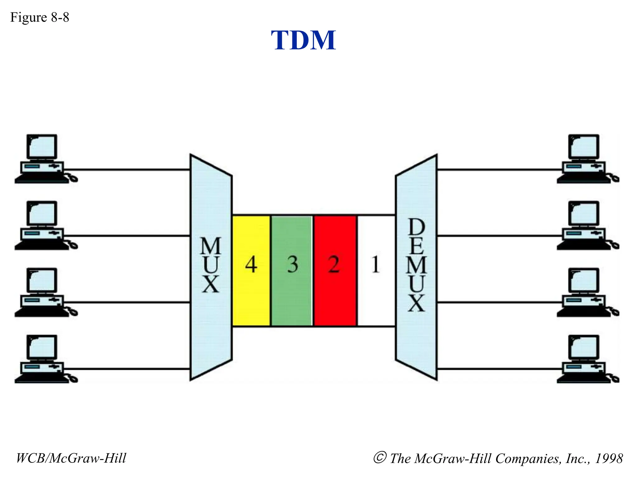
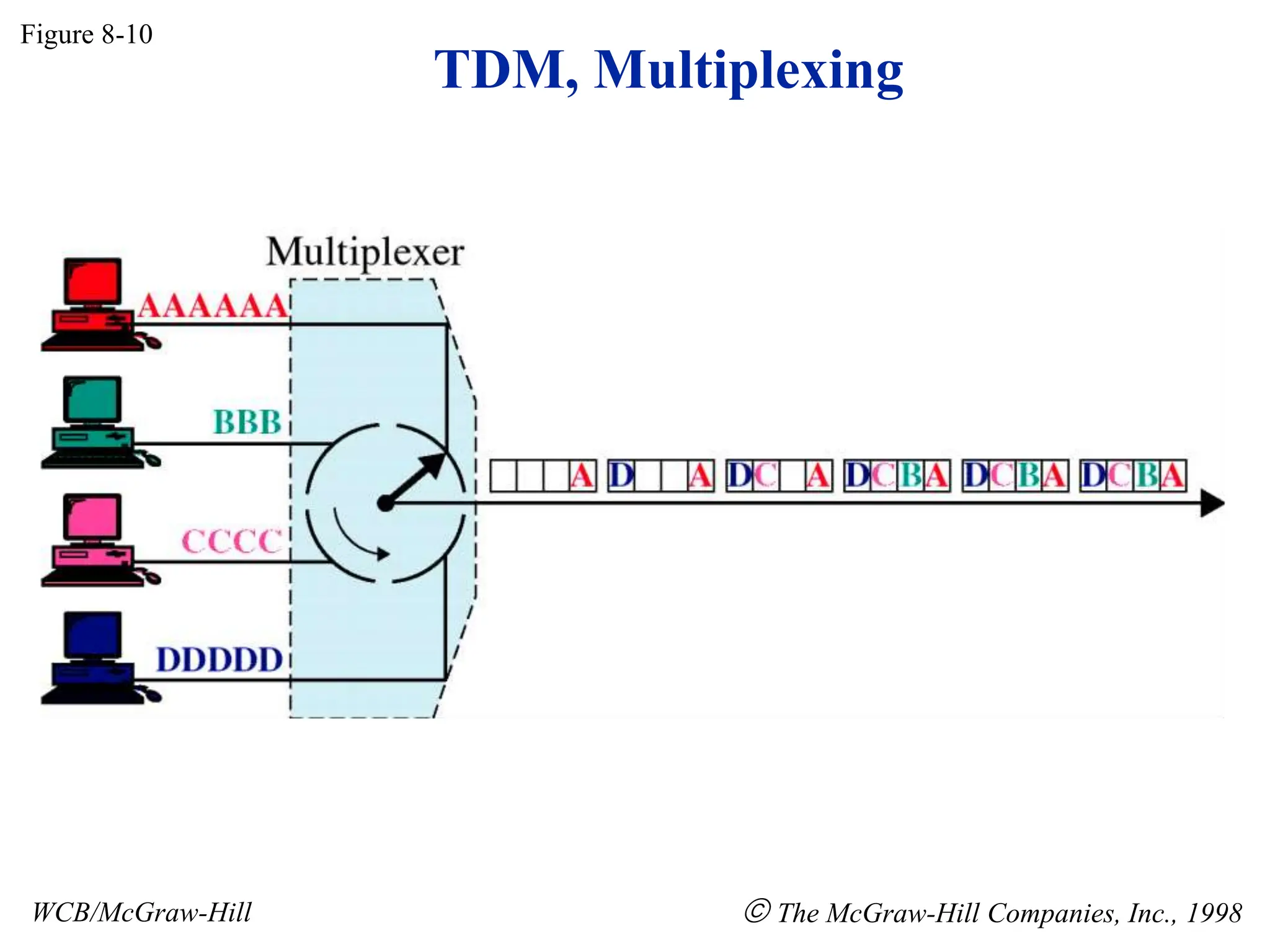
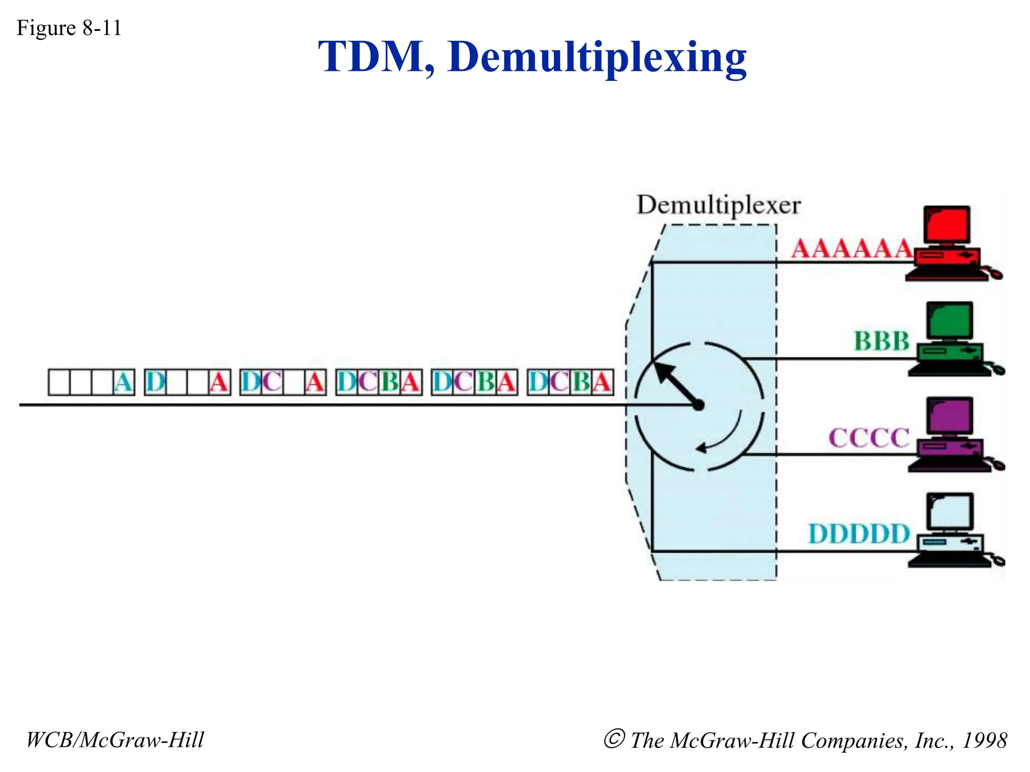
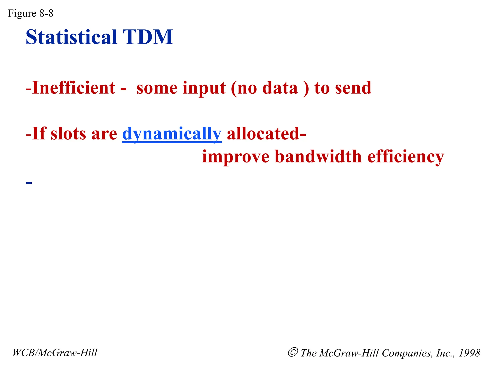
- Multiplexing techniques including frequency division multiplexing (FDM), wavelength division multiplexing (WDM), and time division multiplexing (TDM).


![2[1].1 data transmission](https://cdn.slidesharecdn.com/ss_thumbnails/21-1-datatransmission-111203164944-phpapp01-thumbnail.jpg?width=640&height=640&fit=bounds)


![Number_Guessing_Game_Dsbsbssbzboc[1].pptx](https://cdn.slidesharecdn.com/ss_thumbnails/numberguessinggamedoc1-251206215042-a076fc05-thumbnail.jpg?width=640&height=640&fit=bounds)


