


![207
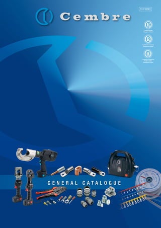
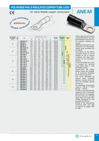
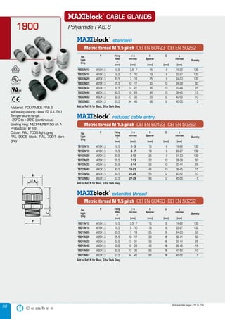
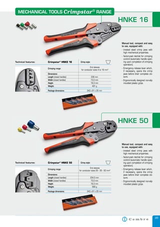
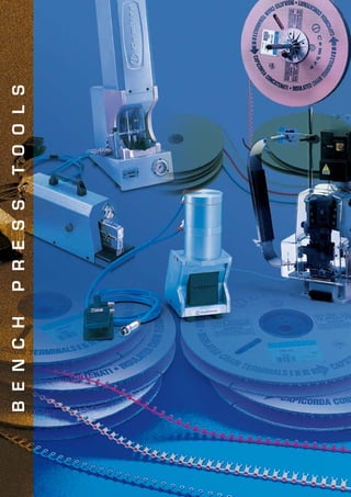
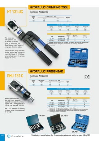
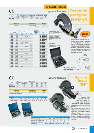
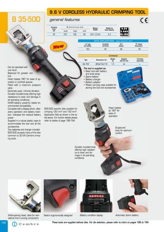
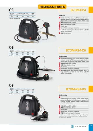
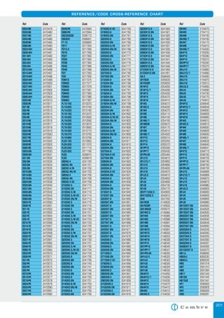
IEC 60228 : 2004 - 11 CONDUCTOR TABLES
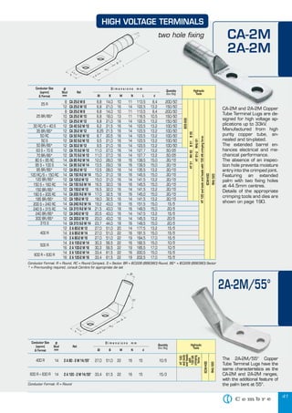
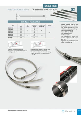
MINIMUM AND MAXIMUM DIAMETERS OF STRANDED COMPACTED CIRCULAR COPPER, ALUMINIUM AND ALUMINIUM ALLOY CONDUCTORS
Cross-sectional area
[mm2
]
Stranded compacted circular conductors (Class 2)
Minimum diameter
[mm]
Maximum diameter
[mm]
10 3,6 4,0
16 4,6 5,2
25 5,6 6,5
35 6,6 7,5
50 7,7 8,6
70 9,3 10,2
95 11,0 12,0
120 12,3 13,5
150 13,7 15,0
185 15,3 16,8
240 17,6 19,2
300 19,7 21,6
400 22,3 24,6
500 25,3 27,6
630 28,7 32,5
NOTES: - The dimensional limits of Aluminium conductors with cross-sectional areas above 630 mm2
are not given as the compaction technology is not generally estabilished.2
are not given as the compaction technology is not generally estabilished.2
- The values are given for compacted Copper conductors in the size range 1,5 mm2
to 6 mm2
to 6 mm2 2
.
MAXIMUM DIAMETERS OF CIRCULAR COPPER CONDUCTORS: SOLID, NON COMPACTED STRANDED AND FLEXIBLE
Cross sectional area
[mm2
]
Conductors in cables for fixed installations
Flexible conductors (Classes 5 and 6)
Maximum diameter [mm]Solid (Class 1)
Maximum diameter [mm]
Stranded (Class 2)
Maximum diameter [mm]
0,5 0,9 1,1 1,1
0,75 1,0 1,2 1,3
1 1,2 1,4 1,5
1,5 1,5 1,7 1,8
2,5 1,9 2,2 2,4
4 2,4 2,7 3,0
6 2,9 3,3 3,9
10 3,7 4,2 5,1
16 4,6 5,3 6,3
25 a
5,7 6,6 7,8
35 a
6,7 7,9 9,2
50 a
7,8 9,1 11,0
70 a
9,4 11,0 13,1
95 a
11,0 12,9 15,1
120 a
12,4 14,5 17,0
150 a
13,8 16,2 19,0
185 15,4 18,0 21,0
240 17,6 20,6 24,0
300 19,8 23,1 27,0
400 22,2 26,1 31,0
500 - 29,2 35,0
630 - 33,2 39,0
800 - 37,6 -
1000 - 42,2 -
NOTE The values given for flexible conductors represent both class 5 and class 6 conductors.
a
Solid Copper conductor shaving cross-sectional areas of 25 mma
Solid Copper conductor shaving cross-sectional areas of 25 mma 2
and above are for particular types of cable, e.g. mineral insulated, and not for general purposes.2
and above are for particular types of cable, e.g. mineral insulated, and not for general purposes.2
MINIMUM AND MAXIMUM DIAMETERS OF CIRCULAR ALUMINIUM CONDUCTORS
Cross-sectional area
[mm2
]
Solid conductors (Class 1)
Minimum diameter
[mm]
Maximum diameter
[mm]
10 3,4 3,7
16 4,1 4,6
25 5,2 5,7
35 6,1 6,7
50 7,2 7,8
70 8,7 9,4
95 10,3 11,0
120 11,6 12,4
150 12,9 13,8
185 14,5 15,4
240 16,7 17,6
300 18,8 19,8
400 21,2 22,2
500 24,0 25,1
630 27,3 28,4
800 30,9 32,1
1000 34,8 36,0
1200 37,8 39,0](https://image.slidesharecdn.com/generalcatalogueltd13v029e-130617025158-phpapp01/85/Cembre-Hydraulic-Tools-Mechanical-Tools-Crimping-Tools-Cable-Cutters-ATEX-Cable-Glands-Cable-Clamps-Copper-Crimping-Lugs-HV-Copper-Terminals-Terminals-Connectors-207-320.jpg)
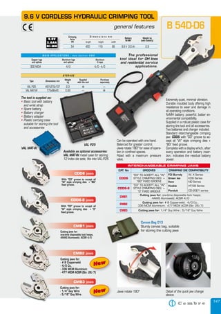
![208
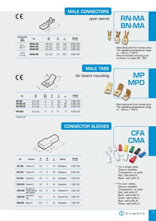
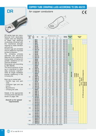
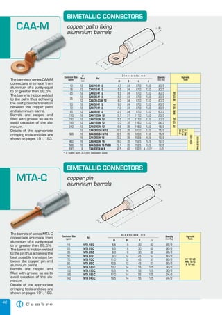
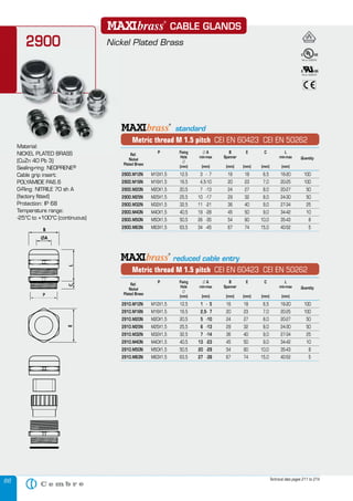
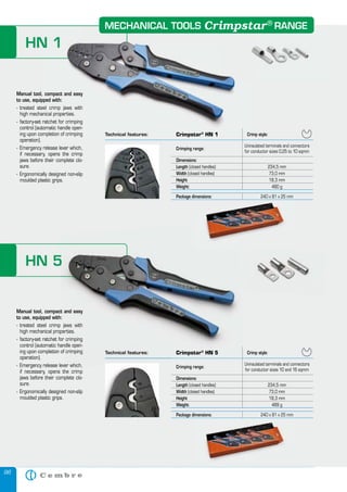
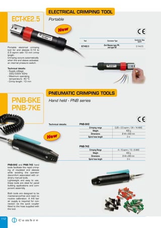
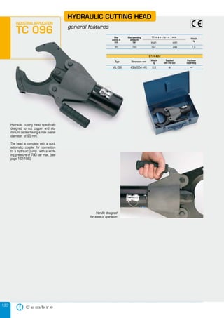
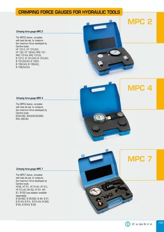
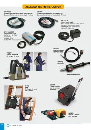
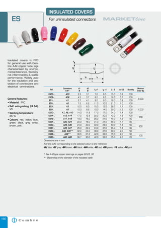
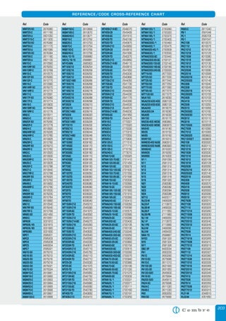
IEC 60228 : 2004 - 11 CONDUCTOR TABLES
CLASS 1:
SOLID CONDUCTORS FOR SINGLE-CORE AND MULTI-CORE CABLES
Nominal cross-sectional
[mm2
]
Maximum resistance of conductor at 20 °C
Circular, annealed Copper conductors Aluminium and Aluminium alloy conductors,
circular or shaped c
[ohm/km]Plain [ohm/km] Metal [ohm/km]
0,5 36 36,7 -
0,75 24,5 24,8 -
1 18,1 18,2 -
1,5 12,1 12,2 -
2,5 7,41 7,56 -
4 4,61 4,70 -
6 3,08 3,11 -
10 1,83 1,84 3,08 a
16 1,15 1,16 1,91 a
25 0,727 b
- 1,20 a
35 0,524 b
- 0,868 a
50 0,387 b
- 0,641
70 0,268 b
- 0,443
95 0,193 b
- 0,320 d
120 0,153 b
- 0,253 d
150 0,124 b
- 0,206 d
185 0,101 b
- 0,164 d
240 0,0775 b
- 0,125 d
300 0,0620 b
- 0,100 d
400 0,0465 b
- 0,0778
500 - - 0,0605
630 - - 0,0469
800 - - 0,0367
1000 - - 0,0291
1200 - - 0,0247
aaa
Aluminium conductors 10 mm2
to 35 mm2
to 35 mm2 2
circular only2
circular only2
bbb
Solid Copper conductors having nominal cross-sectional area of 25 mm2
and above are for particular types of cable, e.g. mineral insulated, and not for general purposes.2
and above are for particular types of cable, e.g. mineral insulated, and not for general purposes.2
ccc
For solid Aluminium alloy conductors, having the same nominal cross-sectional area as an Aluminium conductor, the resistance value given in the table should be multiplied by a factor of
1,162 unless otherwise agreed between the manufacturer and the purchaser.
ddd
For single core cables, four sectoral shaped conductors may be assembled into a single circular conductor. The maximum resistance of the assembled conductor shall be 25% of that of the
individual component conductors.
CLASS 2:
STRANDED CONDUCTORS FOR SINGLE-CORE AND MULTI-CORE CABLES
Nominal cross-
sectional area
[mm2
]
Minimum number of wires in the conductor Maximum resistance of conductor at 20 °C
Circular Circular compacted Shaped Annealed copper conductor Aluminium or Aluminium
alloy conductor c
[ohm/
km]Cu Al Cu Al Cu Al Plain wires [ohm/km]
Metal-coated wires
[ohm/km]
0,5 7 - - - - - 36,0 36,7 -
0,75 7 - - - - - 24,5 24,8 -
1,0 7 - - - - - 18,1 18,2 -
1,5 7 - 6 - - - 12,1 12,2 -
2,5 7 - 6 - - - 7,41 7,56 -
4 7 - 6 - - - 4,61 4,70 -
6 7 - 6 - - - 3,08 3,11 -
10 7 7 6 6 - - 1,83 1,84 3,08
16 7 7 6 6 - - 1,15 1,16 1,91
25 7 7 6 6 6 6 0,727 0,734 1,20
35 7 7 6 6 6 6 0,524 0,529 0,868
50 19 19 6 6 6 6 0,387 0,391 0,641
70 19 19 12 12 12 12 0,268 0,270 0,443
95 19 19 15 15 15 15 0,193 0,195 0,320
120 37 37 18 15 18 15 0,153 0,154 0,253
150 37 37 18 15 18 15 0,124 0,126 0,206
185 37 37 30 30 30 30 0,0991 0,100 0,164
240 61 61 34 30 34 30 0,0754 0,0762 0,125
300 61 61 34 30 34 30 0,0601 0,0607 0,100
400 61 61 53 53 53 53 0,0470 0,0475 0,0778
500 61 61 53 53 53 53 0,0366 0,0369 0,0605
630 91 91 53 53 53 53 0,0283 0,0286 0,0469
800 91 91 53 53 - - 0,0221 0,0224 0,0367
1000 91 91 53 53 - - 0,0176 0,0177 0,0291
1200 b
b
b
b
b
b
0,0151 0,0151 0,0247
1400 a
0,0129 0,0129 0,0212
1600 0,0113 0,0113 0,0186
1800 a
0,0101 0,0101 0,0165
2000 0,0090 0,0090 0,0149
2500 0,0072 0,0072 0,0127
a
Non-preferred sizes. Other non-preferred sizes are recognized for some specialized applications but are not within the scope of this standard.a
Non-preferred sizes. Other non-preferred sizes are recognized for some specialized applications but are not within the scope of this standard.a
b
The minimum number of wires for these sizes is not specified. These sizes may be constructed from 4, 5 or 6 equal segments (Milliken).b
The minimum number of wires for these sizes is not specified. These sizes may be constructed from 4, 5 or 6 equal segments (Milliken).b
c
For stranded Aluminium alloy conductors having the same nominal cross-sectional area as an Aluminium conductor the resistance value should be agreed between the manufacturer and the purchaser.Aluminium conductor the resistance value should be agreed between the manufacturer and the purchaser.Aluminium](https://image.slidesharecdn.com/generalcatalogueltd13v029e-130617025158-phpapp01/85/Cembre-Hydraulic-Tools-Mechanical-Tools-Crimping-Tools-Cable-Cutters-ATEX-Cable-Glands-Cable-Clamps-Copper-Crimping-Lugs-HV-Copper-Terminals-Terminals-Connectors-208-320.jpg)
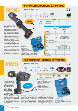
![209
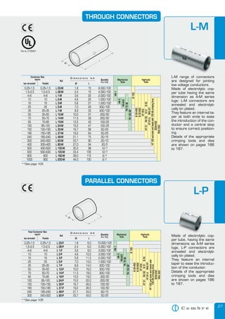
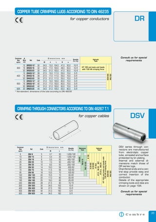
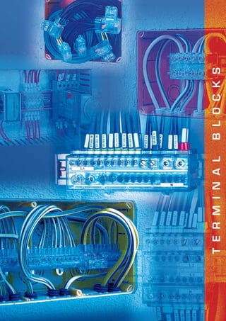
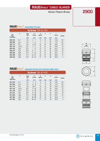
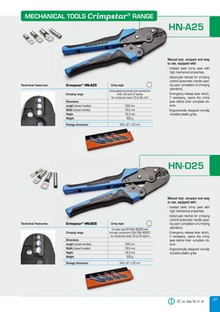
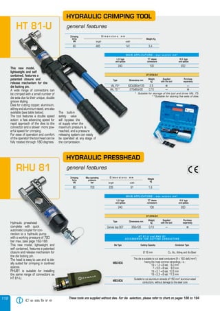
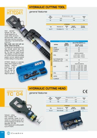
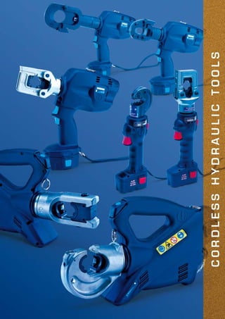
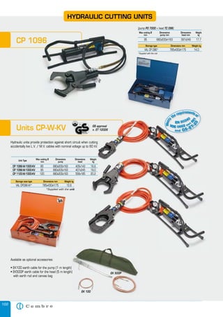
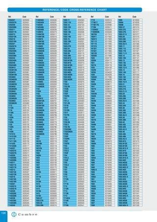
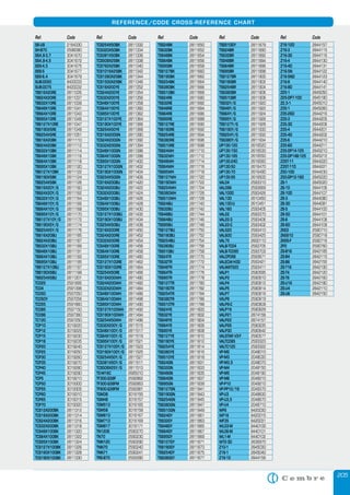
IEC 60228 : 2004 - 11 CONDUCTOR TABLES
CLASS 5:
FLEXIBLE COPPER CONDUCTORS FOR SINGLE-CORE AND MULTI-CORE CABLES
Nominal cross-sectional
[mm2
]
Maximum diameter of wires in conductor
[mm]
Maximum resistance of conductor at 20 °C
Plain wires [ohm/km] Metal-coated wires [ohm/km]
0,5 0,21 39,0 40,1
0,75 0,21 26,0 26,7
1,0 0,21 19,5 20,0
1,5 0,26 13,3 13,7
2,5 0,26 7,98 8,21
4 0,31 4,95 5,09
6 0,31 3,30 3,39
10 0,41 1,91 1,95
16 0,41 1,21 1,24
25 0,41 0,780 0,795
35 0,41 0,554 0,565
50 0,41 0,386 0,393
70 0,51 0,272 0,277
95 0,51 0,206 0,210
120 0,51 0,161 0,164
150 0,51 0,129 0,132
185 0,51 0,106 0,108
240 0,51 0,0801 0,0817
300 0,51 0,0641 0,0654
400 0,51 0,0486 0,0495
500 0,61 0,0384 0,0391
630 0,61 0,0287 0,0292
CLASS 6:
FLEXIBLE COPPER CONDUCTORS FOR SINGLE-CORE AND MULTI-CORE CABLES
Nominal cross-sectional
[mm2
]
Maximum diameter of wires in conductor
[mm]
Maximum resistance of conductor at 20 °C
Plain wires [ohm/km] Metal-coated wires [ohm/km]
0,5 0,16 39,0 40,1
0,75 0,16 26,0 26,7
1.0 0,16 19,5 20,0
1,5 0,16 13,3 13,7
2,5 0,16 7,98 8,21
4 0,16 4,95 5,09
6 0,21 3,30 3,39
10 0,21 1,91 1,95
16 0,21 1,21 1,24
25 0,21 0,780 0,795
35 0,21 0,554 0,565
50 0,31 0,386 0,393
70 0,31 0,272 0,277
95 0,31 0,206 0,210
120 0,31 0,161 0,164
150 0,31 0,129 0,132
185 0,41 0,106 0,108
240 0,41 0,0801 0,0817
300 0,41 0,0641 0,0654](https://image.slidesharecdn.com/generalcatalogueltd13v029e-130617025158-phpapp01/85/Cembre-Hydraulic-Tools-Mechanical-Tools-Crimping-Tools-Cable-Cutters-ATEX-Cable-Glands-Cable-Clamps-Copper-Crimping-Lugs-HV-Copper-Terminals-Terminals-Connectors-209-320.jpg)

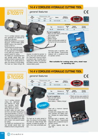
![211
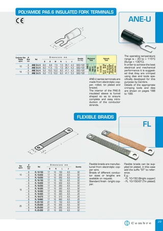
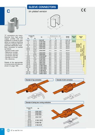
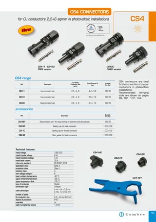
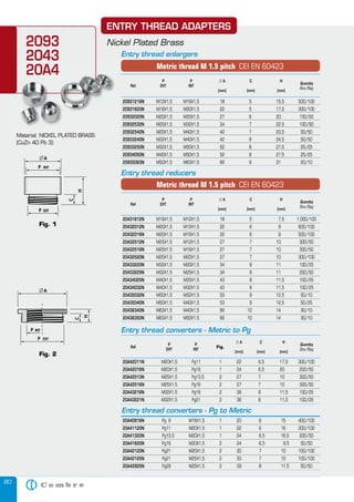
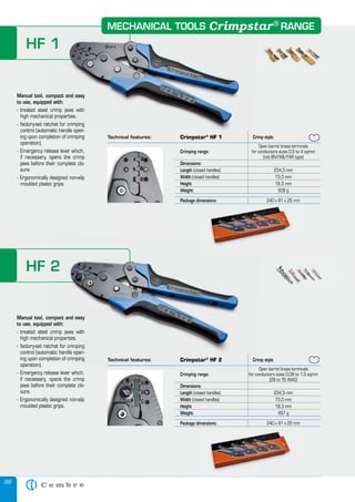
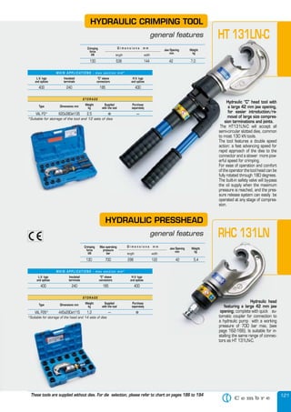
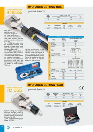
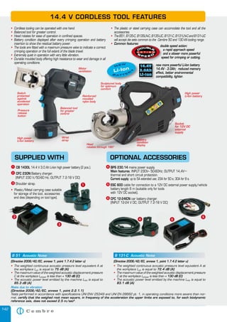
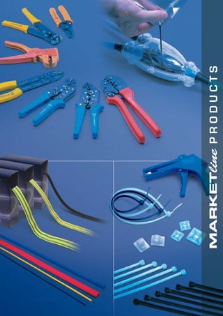
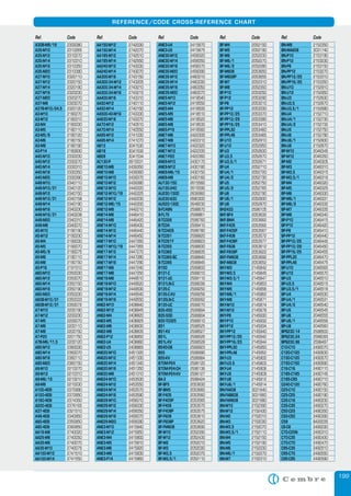
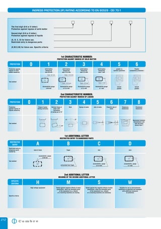
UL AND VDE MARKING OF CABLE GLANDS
VDE: Licence nos 40008472, 40008474, 40008475 and 40008476
USL-CNL: UL LISTING file no E220310; control no 48SB valid in USA & Canada
USR-CNR: UL RECOGNITION file no E220310 valid in USA & Canada (with reduced tightening force)
(*) EN 50262 § 9.4
-
Add to Ref: N for Black, G for Dark Grey
USR-CNR
USR-CNR
USR-CNR
USL-CNL
USL-CNL
USL-CNL
USL-CNL
USL-CNL
USL-CNL
USL-CNL
USR-CNR
USR-CNR
USL-CNL
USL-CNL
USL-CNL
USL-CNL
USL-CNL
USR-CNR
USR-CNR
USR-CNR
USL-CNL
USL-CNL
USL-CNL
USR-CNR
USR-CNR
USL-CNL
USL-CNL
USL-CNL
USR-CNR
USR-CNR
USL-CNL
USL-CNL
Pg 7
Pg 9
Pg 11
Pg 13,5
Pg 16
Pg 21
Pg 29
Pg 36
Pg 42
Pg 48
Pg 9
Pg 11
Pg 13,5
Pg 16
Pg 21
Pg 29
Pg 36
Pg 7
Pg 9
Pg 11
Pg 13,5
Pg 16
Pg 21
G1/4”
G3/8”
G1/2”
G3/4”
G1/2”
G1/4”
G3/8”
G1/2”
G3/4”
3,5-7
5-8
5-10
7-12
10-14
13-18
18-25
20-32
28-38
37-45
5-8
5-10
7-12
10-14
13-18
18-25
20-32
3,5-7
5-8
5-10
7-12
10-14
13-18
3-6,5
4-8
7-12
13-18
7-12
3-6,5
4-8
7-12
13-18
4.5-6.5
5.5-8
6.5-9.5
8-11.5
10.5-14
13-18
18.5-25
21.5-32
28-38
40-44
5.5-8
6.5-9.5
8-11.5
10.5-14
13-18
18.5-25
21.5-32
4.5-6.5
5.5-8
6.5-9.5
8-11.5
10.5-14
13-18
4.5-6.5
5.5-8
8-11.5
13-18
8-11.5
4.5-6.5
5.5-8
8-11.5
13-18
0.18-0.25
0.22-0.31
0.26-0.37
0.31-0.45
0.41-0.55
0.51-0.71
0.73-0.98
0.85-1.26
1.10-1.49
1.57-1.73
0.22-0.31
0.26-0.37
0.31-0.45
0.41-0.55
0.51-0.71
0.73-0.98
0.85-1.26
0.18-0.25
0.22-0.31
0.26-0.37
0.31-0.45
0.41-0.55
0.51-0.71
0.18-0.25
0.22-0.31
0.31-0.45
0.51-0.71
0.31-0.45
0.18-0.25
0.22-0.31
0.31-0.45
0.51-0.71
1900.07
1900.09
1900.11
1900.13
1900.16
1900.21
1900.29
1900.36
1900.42
1900.48
1901.09
1901.11
1901.13
1901.16
1901.21
1901.29
1901.36
1500.07
1500.09
1500.11
1500.13
1500.16
1500.21
1900.14
1900.38
1900.12
1900.34
1901.12
1500.14
1500.38
1500.12
1500.34
COMPRESSION RANGE
Ø min-maxRef.
Light
Grey
Thread
UL 514B
[mm] [inches]
MARKING
Nominal
[mm]
Ref.
Nickel
Plated
Brass
Thread MARKING
M12x1,5
M16x1,5
M20x1,5
M25x1,5
M32x1,5
M40x1,5
M50x1,5
M63x1,5
M12x1,5
M16x1,5
M20x1,5
M25x1,5
M32x1,5
M40x1,5
M50x1,5
M63x1,5
M12x1,5
M16x1,5
M20x1,5
M25x1,5
M32x1,5
M40x1,5
M50x1,5
M12x1,5
M16x1,5
M20x1,5
M25x1,5
M32x1,5
M40x1,5
M50x1,5
3-7
4,5-10
7-13
10-17
11-21
19-28
26-35
34-45
1-5
2,5-7
5-10
6-13
7-14
13-23
20-29
27-39
3-7
4,5-10
7-13
10-17
11-21
19-28
26-35
1-5
2,5-7
5-10
6-13
7-14
13-23
20-29
3-7
4,5-10
8-13
10-17
11-21
19-28
27-35
34-45
2-5
3,5-7
5-10
6-13
7-14
15-23
20-29
28-39
3-7
4,5-10
8-13
10-17
11-21
19-28
27-35
2-5
3,5-7
5-10
6-13
7-14
15-23
20-29
0.12-0.28
0.18-0.39
0.31-0.51
0.39-0.67
0.43-0.83
0.75-1.10
1.06-1.38
1.33-1.77
0.08-0.20
0.14-0.28
0.20-0.39
0.24-0.51
0.28-0.55
0.59-0.90
0.79-1.14
1.10-1.54
0.12-0.28
0.18-0.39
0.31-0.51
0.39-0.67
0.43-0.83
0.75-1.10
1.06-1.38
0.08-0.20
0.14-0.28
0.20-0.39
0.24-0.51
0.28-0.55
0.59-0.90
0.79-1.14
3-7
4,5-10
7-13
10-17
11-21
19-28
26-35
34-45
1-5
2,5-7
5-10
6-13
7-14
17-23
22-29
31-39
3-7
4,5-10
7-13
10-17
11-21
19-28
26-35
1-5
2,5-7
5-10
6-13
7-14
13-23
22-29
USR-CNR / VDE
USL-CNL / VDE
USL-CNL / VDE
USL-CNL / VDE
USL-CNL / VDE
USL-CNL / VDE
USL-CNL / VDE
USL-CNL / VDE
USR-CNR / VDE
USR-CNR / VDE
USR-CNR / VDE
USR-CNR / VDE
USR-CNR / VDE
USL-CNL / VDE
USL-CNL / VDE
USL-CNL / VDE
USR-CNR/VDE
USL-CNL / VDE
USL-CNL / VDE
USL-CNL / VDE
USL-CNL / VDE
USL-CNL / VDE
USL-CNL / VDE
USR-CNR/VDE
USR-CNR / VDE
USR-CNR / VDE
USR-CNR / VDE
USR-CNR/VDE
USL-CNL / VDE
USL-CNL / VDE
2900.M12N
2900.M16N
2900.M20N
2900.M25N
2900.M32N
2900.M40N
2900.M50N
2900.M63N
2910.M12N
2910.M16N
2910.M20N
2910.M25N
2910.M32N
2910.M40N
2910.M50N
2910.M63N
2901.M12N
2901.M16N
2901.M20N
2901.M25N
2901.M32N
2901.M40N
2901.M50N
2911.M12N
2911.M16N
2911.M20N
2911.M25N
2911.M32N
2911.M40N
2911.M50N
EN 50262
[mm]
UL 514B
[mm] [inches]
Nominal
[mm]
COMPRESSION RANGE
Ø min-max IMPACT
CATEGORY
(*)
5
6
6
6
6
6
6
6
5
6
6
6
6
6
6
6
5
6
6
6
6
6
6
5
6
6
6
6
6
6
-
USR-CNR / VDE
USR-CNR / VDE
USL-CNL / VDE
USL-CNL / VDE
USL-CNL / VDE
USL-CNL / VDE
USL-CNL / VDE
USL-CNL / VDE
USR-CNR / VDE
USR-CNR / VDE
USR-CNR / VDE
USR-CNR / VDE
USR-CNR / VDE
USL-CNL / VDE
USL-CNL / VDE
USL-CNL / VDE
USR-CNR / VDE
USR-CNR / VDE
USL-CNL / VDE
USL-CNL / VDE
USL-CNL / VDE
USL-CNL / VDE
USL-CNL / VDE
USL-CNL / VDE
USR-CNR / VDE
USR-CNR / VDE
USL-CNL / VDE
USL-CNL / VDE
USL-CNL / VDE
USL-CNL
USL-CNL
M12x1,5
M16x1,5
M20x1,5
M25x1,5
M32x1,5
M40x1,5
M50x1,5
M63x1,5
M12x1,5
M16x1,5
M20x1,5
M25x1,5
M32x1,5
M40x1,5
M50x1,5
M63x1,5
M12x1,5
M16x1,5
M20x1,5
M25x1,5
M32x1,5
M40x1,5
M50x1,5
M63x1,5
M12x1,5
M16x1,5
M20x1,5
M25x1,5
M32x1,5
M25x1,5
M25x1,5
3,5-7
5-10
7-13
10-17
13-21
19-28
27-35
34-45
2-5
3-7
5-10
7-13
8-14
15-23
21-29
27-39
3,5-7
5-10
7-13
10-17
13-21
19-28
27-35
34-45
3,5-7
5-10
7-13
10-17
13-21
13-18
13-18
3,5
7
13
17
15-21
21-28
27-34
35-45
2-5
4-7
5-10
7-13
8-14
15-23
21-29
28-39
3,5
7
13
17
15-21
21-28
27-34
35-45
3,5
7
13
17
15-21
13-18
13-18
0.14
0.28
0.51
0.67
0.60-0.83
0.83-1.10
1.06-1.34
1.38-1.77
0.08-0.20
0.16-0.28
0.20-0.40
0.28-0.51
0.31-0.55
0.59-0.91
0.83-1.14
1.1-1.54
0.14
0.28
0.51
0.67
0.60-0.83
0.83-1.10
1.06-1.34
1.38-1.77
0.14
0.28
0.51
0.67
0.60-0.83
0.51-0.71
0.51-0.71
3,5-7
7-10
7-13
10-17
13-21
19-28
27-35
34-45
2-5
4-7
5-10
7-13
8-14
15-23
21-29
27-39
3,5-7
7-10
7-13
10-17
13-21
19-28
27-35
34-45
3,5-7
7-10
7-13
10-17
13-21
-
-
1900.M12
1900.M16
1900.M20
1900.M25
1900.M32
1900.M40
1900.M50
1900.M63
1910.M12
1910.M16
1910.M20
1910.M25
1910.M32
1910.M40
1910.M50
1910.M63
1901.M12
1901.M16
1901.M20
1901.M25
1901.M32
1901.M40
1901.M50
1901.M63
1500.M12
1500.M16
1500.M20
1500.M25
1500.M32
1940.M25
1540.M25
COMPRESSION RANGE
Ø min-maxRef.
Light
Grey
Thread
UL 514B
[mm] [inches]
EN 50262
[mm]
MARKING
Nominal
[mm]
IMPACT
CATEGORY
(*)
1
1
3
3
3
3
3
3
1
1
3
3
3
3
3
3
1
1
3
3
3
3
3
3
1
1
3
3
3
-
-
Add to Ref: N for Black, G for Dark Grey
Ref.
Nickel
Plated
Brass
Thread MARKING
Pg 7
Pg 9
Pg 11
Pg 13,5
Pg 16
Pg 21
Pg 29
Pg 36
Pg 42
Pg 48
Pg 7
Pg 9
Pg 11
Pg13,5
Pg 16
Pg 21
Pg 29
Pg 36
Pg 42
Pg 48
Pg 7
Pg 9
Pg 11
Pg13,5
Pg 16
Pg 21
Pg 29
Pg 36
Pg 42
Pg 7
Pg 9
Pg 11
Pg13,5
Pg 16
Pg 21
Pg29
Pg36
Pg42
3-7
4-8
4,5-10
5-12
7-13
10-17
17-25
20-32
28-38
34-45
1-5
2-6
2,5-7
4-10
5-10
6-13
11-20
18-26
24-31
27-39
3-7
4-8
4,5-10
5-12
7-13
10-17
17-25
20-32
28-38
1-5
2-6
2,5-7
4-10
5-10
6-13
11-20
18-26
24-31
3-7
4-8
4,5-10
9-12
10-13
12-17
18-25
22-32
28-35
34-45
1-5
3-6
3,5-7
5,5-10
6-10
7-13
12-20
19-26
24-31
31-39
3-7
4-8
4,5-10
9-12
10-13
12-17
18-25
22-32
28-35
1-5
3-8
3,5-7
5,5-10
6-10
7-13
12-20
19-26
24-31
0.12-0.28
0.16-0.31
0.18-0.39
0.35-0.47
0.39-0.51
0.47-0.67
0.71-0.98
0.86-1.26
1.10-1.38
1.33-1.77
0.04-0.20
0.12-0.24
0.14-0.28
0.22-0.39
0.24-0.39
0.28-0.51
0.47-0.79
0.75-1.02
0.94-1.22
1.22-1.54
0.12-0.28
0.16-0.31
0.18-0.39
0.35-0.47
0.39-0.51
0.47-0.67
0.71-0.98
0.86-1.26
1.10-1.38
0.04-0.20
0.12-0.31
0.14-0.28
0.22-0.39
0.24-0.39
0.28-0.51
0.47-0.79
0.75-1.02
0.94-1.22
USR-CNR
USR-CNR
USR-CNR
USL-CNL
USL-CNL
USL-CNL
USL-CNL
USL-CNL
USL-CNL
USL-CNL
USR-CNR
USR-CNR
USR-CNR
USR-CNR
USR-CNR
USR-CNR
USR-CNR
USL-CNL
USL-CNL
USL-CNL
USR-CNR
USR-CNR
USR-CNR
USL-CNL
USL-CNL
USL-CNL
USL-CNL
USL-CNL
USL-CNL
USR-CNR
USR-CNR
USR-CNR
USR-CNR
USR-CNR
USR-CNR
USR-CNR
USL-CNL
USL-CNL
2900.07N
2900.09N
2900.11N
2900.13N
2900.16N
2900.21N
2900.29N
2900.36N
2900.42N
2900.48N
2910.07N
2910.09N
2910.11N
2910.13N
2910.16N
2910.21N
2910.29N
2910.36N
2910.42N
2910.48N
2901.07N
2901.09N
2901.11N
2901.13N
2901.16N
2901.21N
2901.29N
2901.36N
2901.42N
2911.07N
2911.09N
2911.11N
2911.13N
2911.16N
2911.21N
2911.29N
2911.36N
2911.42N
UL 514B
[mm] [inches]
Nominal
[mm]
COMPRESSION RANGE
Ø min-max](https://image.slidesharecdn.com/generalcatalogueltd13v029e-130617025158-phpapp01/85/Cembre-Hydraulic-Tools-Mechanical-Tools-Crimping-Tools-Cable-Cutters-ATEX-Cable-Glands-Cable-Clamps-Copper-Crimping-Lugs-HV-Copper-Terminals-Terminals-Connectors-211-320.jpg)


Cembre S.p.A. is a certified manufacturer of electrical connectors and accessories based in Brescia, Italy, with a commitment to quality and environmental management. The company has achieved ISO 9001 certification for its quality management system and ISO 14001 for environmental management, as well as OHSAS 18001 for occupational health and safety. The catalogue outlines a wide range of standard products and emphasizes Cembre's focus on product quality and customer service.


