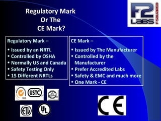
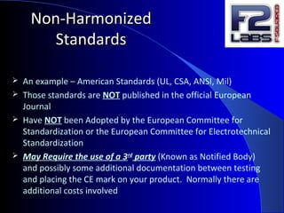
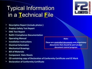
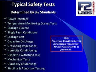
THETHE MARKMARK
******************
Where Do I Start?Where Do I Start?
Revised 05AUG13el
Real-time
diagnostics
as you
test
Our Goal
is to have your
product PASS
all tests required!
CERTIFICATIONS
CE
FCC
Industry Canada
R&TTE
Safety Listings
C-Tick
LVD
MACHINERY
PRODUCTS TESTED
Medical Devices
Laboratory Equipment
Industrial/ Machinery
Household Appliances
Audio/Video
Transmitters
Receivers
IT
& More . . .
SERVICES
Test & Assessment
Training/Seminars
Design Reviews
Performance
Site Survey
Field Evaluations
Verifications
Listing Transfers
TESTING
*EMC/EMI
Radio
Safety
Performance
*Immunity &
Emissions Testing
WE’RE YOUR KEY TO WORLD MARKETS!
World Class testing services with a personal touch.
Doing things faster, respond quicker and provide you with personal attention
We get the job done for you in the time frame that you require
Testing in Damascus, Maryland; Middlefield, Ohio or at YOUR facility
The Choices You Make
Now
Can Provide for a Successful
Evaluation
The
Basics
CE stands for Conformité Européenne, which is
French for "European Conformity." A product in
one of the controlled product categories cannot
legally be sold in the EU unless it has passed
the tests to receive the CE marking.
NRTL (Nationally Recognized Test Lab) & ISO 17025
Laboratories are organizations that have
demonstrated as meeting certain Business and
Technical Disciplines
• Capability, Technically & Administratively
• Control Programs
• Complete Independence
• Reporting & Complaint Handling
• Procedures to Test and Certify
OSHA/NRTL &
ISO 17025 Accredited
Labs
Regulatory Mark
Or The
CE Mark?
Regulatory Mark –
• Issued by an NRTL
• Controlled by OSHA
• Normally US and Canada
• Safety Testing Only
• 15 Different NRTLs
CE Mark –
• Issued by The Manufacturer
• Controlled by the
Manufacturer
• Prefer Accredited Labs
• Safety & EMC and much more
• One Mark - CE
Who needs a CE markWho needs a CE mark
and how do I get one?and how do I get one?
It is EU law that every product that enters the
European Union meet the CE Directives and
applicable Standards
• This mark can only be applied to your
product when you have fully complied with all
relevant Directives and Standards for the type
of system you are marketing
• ….and a Declaration of Conformity has been
developed (other types of Declarations exist)
The European UnionThe European Union
Member States of the EU
Austria Belgium
Bulgaria Croatia
Cyprus Denmark
Czech Republic
Estonia Finland
France Germany
Greece Hungary
Ireland Italy
Latvia Lithuania
Luxembourg
Malta Netherlands
Poland Portugal
Romania Slovakia
Spain Sweden
United Kingdom
December 2009
Countries on the road to EU Membership
Iceland Montenegro
Serbia
The former Yugoslav Republic of Macedonia
Turkey
Potential Candidates
Albania Bosnia and Herzegovina Kosovo
The Road to ComplianceThe Road to Compliance
**Keep in mind there are more than just EMC & Safety**Keep in mind there are more than just EMC & Safety
Directives & StandardsDirectives & Standards
CE MARK
DECLARATION OF CONFORMITY
TECHNICAL DOCUMENTATION FILE
DIRECTIVES DIRECTIVES
STANDARDS STANDARDS
• The CE symbol must be affixed on the equipment itself in such
a manner that it cannot be easily removed. The minimum size is
5 mm. (0.2").
• Only if your equipment is too small, or the usage of a sign is
incompatible with the function of your equipment, may it be
used on any accompanying documentation for identification.
5
m
m
What’s aWhat’s a
Directive ?Directive ?
 A Directive is an EU legally binding document
that is provided to facilitate the free movement of goods
and services - Think of it as the Law
 Directives provide for health, safety and environmental
requirements for a wide range of products, ranging from
residential to industrial equipment
Just a few of The DirectivesJust a few of The Directives
http://www.newapproach.org/directiveshttp://www.newapproach.org/directives
HARMONIZED
&
NON-HARMONIZED
STANDARDS
The StandardsThe Standards
HarmonizedHarmonized
StandardsStandards
 Also known as ‘mandated standards’
 Fulfills the requirements of the European Directives
 The standards are published in the Official European Journal
 Adopted by the European Committee for Standardization & the
European Committee for Electrotechnical Standardization
 Widely accepted throughout the world today
Non-HarmonizedNon-Harmonized
StandardsStandards
 An example – American Standards (UL, CSA, ANSI, Mil)
 Those standards are NOT published in the official European
Journal
 Have NOT been Adopted by the European Committee for
Standardization or the European Committee for Electrotechnical
Standardization
 May Require the use of a 3rd
party (Known as Notified Body)
and possibly some additional documentation between testing
and placing the CE mark on your product. Normally there are
additional costs involved
DDeclarationeclaration ooff CConformityonformity
DOCDOC
A Legally Binding Document
> A sworn statement of fact <
• Contains a legal statement that the product complies
with the requirements of the applicable Directives (Laws)
and Standards (test methods)
• Must be signed by a responsible person representing the
Manufacturer. Someone who is accountable for the design,
testing and validity of the DOC
Information RequiredInformation Required
on aon a
DDeclarationeclaration ooff CConformityonformity
 Description of the system or product
 Model Number/Part Number
 Report number (supplied by the Test Lab)
 Directives Used (supplied by the Test Lab)
 Standards Used (supplied by the Test Lab)
 Signature of the Responsible Person
 On your Letter Head or another Company Document
 Dated and signed
TTechnicalechnical FFileile
 All CE marking directives require the manufacturer of the
product to create a technical file which should contain the
information required to show that the product properly
complies with the requirements of the directives which apply to
it.
 It is important to understand that only the authorities given
power to enforce the directives have a right to see the technical
file. It does not need to be published or given to customers.
 The Machinery Directive requires manufacturers based outside
Europe to appoint someone within Europe to act as the contact
point for their technical documents.
 The purpose of the Technical File is to provide evidence for an
enforcement authority that the product has correctly completed
the assessment and attestation procedures of the relevant
directive(s).
Penalties could lead to
any of the following:
 Shipments Stopped at Port
 Fines
 Products Removed From the
Markets
 No Further Sales Within the
European Union
 Imprisonment
What happens if I don’t CE mark my product?
Typical InformationTypical Information
in ain a TTechnicalechnical FFileile
 Descriptive Report (include photos )
 Product Safety Test Report
 EMC Test Report
 RoHS 2 Compliance Documentation
 Operating Manual
 Installation Instructions
 Electrical Schematics
 Mechanical Drawings
 Bill of Materials
 Component Data Sheets
 CD containing copy of Declaration of Conformity Certificate and CE Mark
 Declaration of Conformity Certificate
Note:
These are controlled documents and proprietary
documents that should be part of your
document control program
RAPEX
Rapid Alert System for non-food products
http://ec.europa.eu/consumers/safety/rapex/alerts/main/index.cfm
PRODUCT
ALERT
PROGRAMS
�General Content
• Details of manufacturer, name/address
• Description of the product / Marking / EC declaration of
conformity
• Determination of the use (purpose)
• Warning on remaining dangers and miss use
Also > Information on - - -
Transport, installation, assembly, putting into operation, training,
operation, maintaining and repairing, dismantling, recycling,
& if need be disposal
**Please note: this is not a complete list of requirements
THE
INSTRUCTION
MANUAL
MANUAL
LANGUAGE
REQUIREMENTS
The Language shall be acceptable
by the Country in which the equipment
is to be installed for use
The Documentation intended for use by
Service personnel should be in English
Chinese
Spanish
English
German
French
FIVE
COMMON
LANUAGES
Cuidado
avertir
Warnung
Caution 
警告 , 告誡 ;
What are the Basics
For an RFQ?
 Identify the countries you wish to place the product
 Draw a simple block diagram
Device
Or System
For
Evaluation
220VAC/50Hz/5A
I/O in from PC (3m)
48VDC Motor Power (10m)
I/O out to Actuator (15m)
 List all electrical inputs & outputs and identify if they are
power or I/O
 Provide the maximum lengths for each input & output cable
 Identify any fluid, gas or air requirements and pressures
 Description of the product and where it is used
120psi air inputCourtesy Power Outlet 220VAC
What Do You
Need to do to Prepare
for Testing & Evaluation?
 Provide all requested documentation
by the date F2 Labs has requested.
 Ensure that the product
functions as close as possible
to normal operation for a
continuous period of time
Typical EMC
Supporting Documentation
Needs
 Test Sample Set-Up Instructions
 Operator/Installation Manual
Typical Safety
Supporting Documentation
Needs
 Test Sample Set-Up Instructions
 Operator/Installation/Maintenance Manual
 Electrical Schematics and Wiring Diagrams
 Mechanical Drawings and Block Diagrams
 Drawings of all applied labels
 Bill of Materials (electrical and mechanical)
 Critical Component Data Sheets such as:
Filters, Power Supplies, Transformers, etc.
 Lasers – CDRH or IEC 60825 report
TheThe
EMCEMC DIRECTIVEDIRECTIVE
 The Electro-Magnetic Compatibility Directive applies to all
electronic and electrical products that are manufactured
 Compliance has been mandatory since January 1, 1996
 Simply stated - in order to comply with this Directive the
product must have an adequate level of immunity & shall not
interfere with any other systems or products
EMCEMC is ais a natural conditionnatural condition that exists when electricalthat exists when electrical
equipment is performing its designed functionsequipment is performing its designed functions
withoutwithout
““Causing”Causing” (Emissions) or “(Emissions) or “sufferingsuffering” (Immunity) from” (Immunity) from
unacceptableunacceptable degradation due to electromagnetic interferencedegradation due to electromagnetic interference
toto oror fromfrom other equipmentother equipment
BASICBASIC
EElectro-lectro-MMagneticagnetic
CCompatibilityompatibility
EMC (Electro-Magnetic Compatibility)
2 conditions must be satisfied: The device does not generate
electromagnetic noise and does not malfunction due to
extraneous noise
EMI (Electro-Magnetic Interference)
The device does not generate electromagnetic noise beyond
established levels
EMS (Electro-Magnetic Susceptibility)
The device does not abnormally malfunction due to
extraneous noise within the environment the
device will be used
EMCEMC
-CONTINUED--CONTINUED-
ImmunityImmunity
AKAAKA
SusceptibilitySusceptibility
……a condition that exists when equipment continues to operate withina condition that exists when equipment continues to operate within
acceptable limits of performanceacceptable limits of performance when exposed to interference inwhen exposed to interference in
which the environment where it is usedwhich the environment where it is used
>>>>For Example<<<<>>>>For Example<<<<
Equipment may work fine in a home but may fail if it is placed inside aEquipment may work fine in a home but may fail if it is placed inside a
machine shop. Why? Equipment is immune to themachine shop. Why? Equipment is immune to the low levellow level residentialresidential
disturbances but not immune todisturbances but not immune to high levelhigh level industrial-strengthindustrial-strength
disturbances.disturbances.
Emissions
AKA
Noise / Leaking Radio Frequency
A condition that exists when your equipment suffers from
unacceptable degradation of performance as a result of
electromagnetic interference
>> For Example <<>> For Example <<
You run the vacuum cleaner at your house while the
television in on and the television screen gets staticky.
BASIC CONCEPTBASIC CONCEPT
Electromagnetic Fields Exist Everywhere
It is NORMAL
There are two paths
Radiated
Airborne
&
Conducted Wires
 
TYPICALTYPICAL
EElectro-lectro-MMagneticagnetic
CCompatibility Tesompatibility Teststs
- Radiated Immunity - Harmonics
- Conducted Immunity - Flicker
- Surge - Radiated Emissions
- ESD - Conducted Emissions
- EFT
- Voltage Dips & Interrupts
IMMUNITY TESTS EMISSIONS TESTS
Radiated
Immunity
Evaluated by controlling a signal source
and power levels to generate field levels
over a defined set of frequencies
Radiated
Immunity
Simulation
Consider the acceptable limits
of performance for your device
within the application of use
 Are you using shielded cabling
 Is your enclosure shielded
 Limit your “vent” openings in the enclosure
 Use ferrites on cabling if needed
 Make sure the connectors are grounded
properly
 Make sure the enclosure has a continuous
ground
 Use multi-layer PCBs where possible
Radiated Immunity
Design Tips
Conducted
Immunity
Evaluates the product’s ability to resist
electrical signals that may be generated
by the switching of inductive loads or
contactors
Conducted Immunity
Simulation
Controlled
Signal
Source
Consider the acceptable limits
of performance for your device
within the application of use
Signal injection
Conducted Immunity
Design Tips
 Are you using shielded cabling
 Is your enclosure shielded
 Are there I/O line filters
 Use ferrites on cabling if needed
 Use multi-layer PCBs where possible
 Are you using a power line filter
Surge
Immunity
This tests the equipment’s level of
resistance or immunity to surges
caused by over voltages from
switching and lightning transients
Surge Immunity
Simulation
Controlled
Pulse
Source
Consider the acceptable limits
of performance for your device
within the application of use

Pulse injection

 Use pre-approved power supplies
 Are there surge suppressors installed
Surge Immunity
Design Tips
ESD
Immunity
Electrostatic Discharges are
applied to all relevant points
while the apparatus is in
operation. These are applied
either by air or by touch (contact)

ESD Immunity
Simulation
Consider the acceptable limits
of performance for your device
within the application of use

Electro-static discharge
 

ESD Immunity
Design Tips
Make sure the enclosure has a common
ground plane
Make sure the AC mains has the 3rd
wire
Ground and is used
 If a plastic enclosure, consider conductive
coatings
 With keyboards consider using a
“back-plane” ground sheet
EFT
(Electrical Fast Transients)
Immunity
EFT is a test process to demonstrate
the equipment’s resistance to line
transients through the connecting
leads simulating relay and
contact bounce
EFT Immunity
Simulation
Controlled
Signal
Source
Consider the acceptable limits
of performance for your device
within the application of use
Signal injection
EFT Immunity
Design Tips
 Make sure the enclosure has a
common ground plane
 Does your unit have a power
line filter
 Are there transient suppression
components employed on the PCBA
 Use shielded cables
 Employ multi-layer PCBs
 Use shielded cables
Voltage Dips &
Interrupts
Immunity
Simulates voltage variations,
and interruptions caused by
short circuits or rapid changes
in power. This may cause a sudden
and extreme increase in current and a
reduction in voltage
Voltage Dips/interrupts
Immunity
Simulation
Controlled
Voltage
Source
Consider the acceptable limits
of performance for your device
within the application of use
Voltage injection
Voltage Dips/interrupts
Immunity
Design Tips
 Use pre-approved power supplies
Harmonic
Emissions
Harmonics is a distortion
of a normal sine wave. When a
product produces distortion it
does this at multiples of the power
line frequency are generated.
Harmonic Emissions
Simulation
Signal
Monitoring
Device
Signal monitoring
Coming from the device
Harmonics Emissions Design
Tips
 Use power factor correction circuits
 The current and voltage wave forms
need to be sinusoidal
Flicker
Emissions
The term “flicker” applies to
uncontrolled intermittent
Emissions. It is also known
as surge emission.
For example: when the lights flicker
Flicker Emission Simulation
Current
Monitoring
Device
Current monitoring
Coming from the device
Flicker Emissions
Design Tips
 Use pre-approved power supplies
Intentional RadiatorsIntentional Radiators are subject to rules (FCC,are subject to rules (FCC,
RTTE, etc.) for preventing interference andRTTE, etc.) for preventing interference and
maximizing the available spectrummaximizing the available spectrum
All other electrical products areAll other electrical products are non-intentionalnon-intentional
RadiatorsRadiators, such as electrical circuits, are not, such as electrical circuits, are not
designed to generate RF energy, but do. As adesigned to generate RF energy, but do. As a
result, theyresult, they couldcould interfere with other devicesinterfere with other devices
RADIATEDRADIATED
EMISSIONSEMISSIONS
Radiated
Emissions
Verifies that the product's
RF emissions do not
exceed a level that will
interfere with the
operation of other
electrical devices in the
operating environment
Radiated Emissions
Simulation
Evaluation of
Radiated Emissions at Your
Location –
Clearance Requirements
 Are you using shielded cabling
 Is your enclosure shielded
 Limit your “vent” openings in the enclosure
 Use ferrites on cabling if needed
 Make sure the connectors are grounded
the port properly
 Make sure the enclosure has a continuous
ground
 Use multi-layer PCBs where possible
Radiated Emissions
Design Tips
Conducted
Emissions
This is energy that is
transmitted from an electrical
device through the power cord
and back into the electrical
system
Conducted Emissions
Simulation
Signal
Monitoring
Device
Signal monitoring
Coming from the device
 Are you using shielded cabling
 Is your enclosure shielded
 Limit your “vent” openings in the enclosure
 Use ferrites on cabling if needed
 Make sure the connectors are grounded
the port properly
 Make sure the enclosure has a continuous
ground
 Use multi-layer PCBs where possible
Conducted Emissions
Design Tips
Have you Noticed
Commonality in
Design Tips?
 Shielded cabling
 Grounding
 Filtering where necessary
 Good workmanship practices
 Using approved power supplies
Electrical Ports
Inputs/Outputs
Testing - Guidance
Port Identity
3m and less >3m (9.8 ft.) >10m (32.8 ft.) >30m (98.4 ft.)
Input AC Power Conducted Im.
EFT Im.
Surge Im.
Dips/Interrupts Im.
Output AC Power Conducted Im.
EFT Im.
Surge Im.
Input and Output DC
Power
Conducted Im. Conducted Im
EFT Im.
Surge Im. (EN61326)
Conducted Im.
EFT Im.
Surge Im.
Signal I/O Conducted Im.
EFT Im.
Conducted Im.
EFT Im.
Surge Im.
Functional Earth Conducted Im. Conducted Im,
EFT Im.
Cable length 1 meter = 3.2808399 feet
The productThe product must complymust comply with thewith the designdesign
and testand test requirements of the properrequirements of the proper
safety standardsafety standard
Typical SafetyTypical Safety
RequirementsRequirements
All products placed on the market
must be safe !
Even if there is no specific Directive or
Standard that
applies
General Product Safety Directive 2001/95/EC
Primary Focus BeingPrimary Focus Being
HUMAN & PROPERTY SAFETYHUMAN & PROPERTY SAFETY
• High Energy LevelsHigh Energy Levels
• Mechanical InjuryMechanical Injury
• Fire HazardsFire Hazards
• Electric ShockElectric Shock
There areThere are
4 Basic Safety4 Basic Safety
ConcernsConcerns
 Power InterfacePower Interface
 Temperature Monitoring During TestsTemperature Monitoring During Tests
 Leakage CurrentLeakage Current
 Single Fault ConditionsSingle Fault Conditions
 Leakage TestLeakage Test
 Capacitor DischargeCapacitor Discharge
 Grounding ImpedanceGrounding Impedance
 Humidity ConditioningHumidity Conditioning
 Dielectric Withstand testDielectric Withstand test
 Mechanical TestsMechanical Tests
 Durability of MarkingsDurability of Markings
 Stability & Abnormal TestingStability & Abnormal Testing
Typical Safety TestsTypical Safety Tests
Determined byDetermined by thethe StandardsStandards
Note
For certain Directives there is
A mandatory requirement
for Risk Assessment to be
performed.
Safety
Design Tips For
Product Enclosures
 Top openings 4mm dia × 100mm long
 Bottom openings 2mm dia max × 3mm
spacing or wire mesh or baffle
 Fasteners for covers/filters over hazardous live parts
and mechanical hazards shall require a tool to remove
 Stability: 10° tilt
 Handles capable of withstanding force of four times the weight
of the equipment
Safety
Design Tips For
Grounding, Wiring
 User-accessible conductive parts shall be bonded to the
Protective Earth (PE) ground
 The integrity of the PE bonding shall be assured
 Circuit/wiring connections shall not cause accessible parts to
become live in normal or single fault condition
Safety
Design Tips For
Grounding, Wiring
-CONTINUED-
 PE soldered connection/s require mechanical securing in
addition to solder
 PE shall not be used for other purposes such as fixing
constructional parts
 Hinges and slides shall not be used for PE path
 Exterior metal braids/foils of cables shall not be considered as PE
bonding
 PE conductors may be bare or insulated; clear or green/yellow
for PE insulation color
Safety
Design Tips - General
 Circuit breakers for AC supply are not polarized in Europe
 Accidental loosen of wiring and screws shall not cause accessible
part to become live
 Self-tapping screws and screws of insulating material should not
be used for electrical connections
 Edges, corners accessible to users shall be rounded or smoothed
Minimum Safety
Design Tips
Labels & Markings
 Products shall bear voltage, current, power, and frequency
ratings, model number and company identification markings
 Input & Output ratings
 Convenience outlets marked with voltage and current ratings
 On/off symbols should be used for disconnect switches
 Internal markings – AC terminals identified, PE symbol adjacent
to ground, earth symbol
Safety
Design Tips
Flammability
 Plastics for fire enclosures rated V-1
 PCB rated V-1
 V-2 for plastics enclosures that have other means to prevent the
spread of fire; for example, a metal sub-enclosure
 Plastics in I/O connectors with non-hazardous voltages, rated V-2
 Connectors and plastic on which components are mounted, rated
V-2
 Plastic air filters, rated V-2 or HF-2
 Plastic enclosures and decorative parts outside fire enclosures,
rated HB
 Plastic wire insulation, rated FV-1
RoHS Directive
2011/65/EU
is now a CE Marking
Directive
What does that mean to you?
It means that if you manufacture an electrical/electronic device, product, or equipment, you
can no longer CE-mark your product in accordance with just the Machinery, EMC, Medical Device
or Low Voltage Directive. Compliance with the RoHS Directive is now required before you can
place the CE mark on your product. This should be included on your Declaration of Conformity.
Lead (0.1 %)
Mercury (0.1 %)
Cadmium (0.01 %)
Hexavalent chromium (0.1 %)
Polybrominated biphenyls (PBB) (0.1 %)
Polybrominated diphenyl ethers (PBDE) (0.1 %)
Restricted substances and maximum
concentration values tolerated by weight
in homogeneous materials (Article 4(1))
Here are links to the ROHS Directive and a blue-guide that you should find useful.
http://eur-lex.europa.eu/LexUriServ/LexUriServ.do?uri=OJ:L:2011:174:0088:0110:en:PDF
http://ec.europa.eu/environment/waste/rohs_eee/pdf/faq.pdf
Household Appliances, IT and
Telecommunications Equipment, Consumer
Equipment, Lighting Equipment, Electrical and
Electronic tools, Toys, Leisure and Sports
Equipment.
Products that must comply NOW
Medical Devices and Monitoring and Control Instruments – must
comply by July 22nd, 2014
In vitro diagnostic medical devices – must comply by July 22nd,
2016
Industrial monitoring and control instruments – must comply by
July 22nd, 2017
Extension to all EEE except for the ones explicitly excluded in
Article 2.4 of the Directive - July 23rd, 2019
http://eur-lex.europa.eu/LexUriServ/LexUriServ.do?uri=OJ:L:2011:174:0088:0110:EN:PDF
New Categories that were formerly
excluded
but are now included are:
There are
Other requirements to
Consider Such as
WEEE
REACH
WEEE
European Directive 2012/19/EU (WEEE)
The purpose of this Directive:
• Avoiding of Waste from Electrical and Electronic Equipment
• Reduction of Waste by Recycling and other Means
• Improvement of the environmental with respect to the life cycle of
materials/products
• Collection, Treatment and Reuse of old Electrical- and Electronic
materials
• Responsibility for Treatment, Reuse and environmental correct
REACH
REACH is a European Community Regulation on chemicals and
their safe use.
EU Directive EC 1907/2006 & deals with the
Registration, Evaluation, Authorization and
Restriction of Chemical substances. The new law
entered into force on 1 June 2007.
The new Regulation aims to improve the
protection of human health and the environment
http://ec.europa.eu/enterprise/reach/index_en.htm
F2 Labs can assist you with your testing needs
We offer a full range of compliance testing
services. We are fully equipped to test and
approve a wide range of products and
equipment for organizational and governmental
certifications. In addition, we offer consulting
and educational services and on-site testing can
be performed by request.
With more than 20 years of experience in the
worldwide market, F2 Laboratories can assist
you through the certification process. We’re
committed to providing our customers with
exceptional customer service.
Call 1-877-405-1580 for a quote today
Or email sales@f2labs.com

CE Mark: Where to Start

  • 1.
    THETHE MARKMARK ****************** Where DoI Start?Where Do I Start? Revised 05AUG13el
  • 2.
    Real-time diagnostics as you test Our Goal isto have your product PASS all tests required! CERTIFICATIONS CE FCC Industry Canada R&TTE Safety Listings C-Tick LVD MACHINERY PRODUCTS TESTED Medical Devices Laboratory Equipment Industrial/ Machinery Household Appliances Audio/Video Transmitters Receivers IT & More . . . SERVICES Test & Assessment Training/Seminars Design Reviews Performance Site Survey Field Evaluations Verifications Listing Transfers TESTING *EMC/EMI Radio Safety Performance *Immunity & Emissions Testing WE’RE YOUR KEY TO WORLD MARKETS! World Class testing services with a personal touch. Doing things faster, respond quicker and provide you with personal attention We get the job done for you in the time frame that you require Testing in Damascus, Maryland; Middlefield, Ohio or at YOUR facility
  • 3.
    The Choices YouMake Now Can Provide for a Successful Evaluation
  • 4.
  • 5.
    CE stands forConformité Européenne, which is French for "European Conformity." A product in one of the controlled product categories cannot legally be sold in the EU unless it has passed the tests to receive the CE marking.
  • 6.
    NRTL (Nationally RecognizedTest Lab) & ISO 17025 Laboratories are organizations that have demonstrated as meeting certain Business and Technical Disciplines • Capability, Technically & Administratively • Control Programs • Complete Independence • Reporting & Complaint Handling • Procedures to Test and Certify OSHA/NRTL & ISO 17025 Accredited Labs
  • 7.
    Regulatory Mark Or The CEMark? Regulatory Mark – • Issued by an NRTL • Controlled by OSHA • Normally US and Canada • Safety Testing Only • 15 Different NRTLs CE Mark – • Issued by The Manufacturer • Controlled by the Manufacturer • Prefer Accredited Labs • Safety & EMC and much more • One Mark - CE
  • 8.
    Who needs aCE markWho needs a CE mark and how do I get one?and how do I get one? It is EU law that every product that enters the European Union meet the CE Directives and applicable Standards • This mark can only be applied to your product when you have fully complied with all relevant Directives and Standards for the type of system you are marketing • ….and a Declaration of Conformity has been developed (other types of Declarations exist)
  • 9.
    The European UnionTheEuropean Union Member States of the EU Austria Belgium Bulgaria Croatia Cyprus Denmark Czech Republic Estonia Finland France Germany Greece Hungary Ireland Italy Latvia Lithuania Luxembourg Malta Netherlands Poland Portugal Romania Slovakia Spain Sweden United Kingdom December 2009
  • 10.
    Countries on theroad to EU Membership Iceland Montenegro Serbia The former Yugoslav Republic of Macedonia Turkey Potential Candidates Albania Bosnia and Herzegovina Kosovo
  • 11.
    The Road toComplianceThe Road to Compliance **Keep in mind there are more than just EMC & Safety**Keep in mind there are more than just EMC & Safety Directives & StandardsDirectives & Standards CE MARK DECLARATION OF CONFORMITY TECHNICAL DOCUMENTATION FILE DIRECTIVES DIRECTIVES STANDARDS STANDARDS
  • 12.
    • The CEsymbol must be affixed on the equipment itself in such a manner that it cannot be easily removed. The minimum size is 5 mm. (0.2"). • Only if your equipment is too small, or the usage of a sign is incompatible with the function of your equipment, may it be used on any accompanying documentation for identification. 5 m m
  • 13.
    What’s aWhat’s a Directive?Directive ?  A Directive is an EU legally binding document that is provided to facilitate the free movement of goods and services - Think of it as the Law  Directives provide for health, safety and environmental requirements for a wide range of products, ranging from residential to industrial equipment
  • 14.
    Just a fewof The DirectivesJust a few of The Directives http://www.newapproach.org/directiveshttp://www.newapproach.org/directives
  • 15.
  • 16.
    HarmonizedHarmonized StandardsStandards  Also knownas ‘mandated standards’  Fulfills the requirements of the European Directives  The standards are published in the Official European Journal  Adopted by the European Committee for Standardization & the European Committee for Electrotechnical Standardization  Widely accepted throughout the world today
  • 17.
    Non-HarmonizedNon-Harmonized StandardsStandards  An example– American Standards (UL, CSA, ANSI, Mil)  Those standards are NOT published in the official European Journal  Have NOT been Adopted by the European Committee for Standardization or the European Committee for Electrotechnical Standardization  May Require the use of a 3rd party (Known as Notified Body) and possibly some additional documentation between testing and placing the CE mark on your product. Normally there are additional costs involved
  • 18.
    DDeclarationeclaration ooff CConformityonformity DOCDOC ALegally Binding Document > A sworn statement of fact < • Contains a legal statement that the product complies with the requirements of the applicable Directives (Laws) and Standards (test methods) • Must be signed by a responsible person representing the Manufacturer. Someone who is accountable for the design, testing and validity of the DOC
  • 19.
    Information RequiredInformation Required onaon a DDeclarationeclaration ooff CConformityonformity  Description of the system or product  Model Number/Part Number  Report number (supplied by the Test Lab)  Directives Used (supplied by the Test Lab)  Standards Used (supplied by the Test Lab)  Signature of the Responsible Person  On your Letter Head or another Company Document  Dated and signed
  • 20.
    TTechnicalechnical FFileile  AllCE marking directives require the manufacturer of the product to create a technical file which should contain the information required to show that the product properly complies with the requirements of the directives which apply to it.  It is important to understand that only the authorities given power to enforce the directives have a right to see the technical file. It does not need to be published or given to customers.  The Machinery Directive requires manufacturers based outside Europe to appoint someone within Europe to act as the contact point for their technical documents.  The purpose of the Technical File is to provide evidence for an enforcement authority that the product has correctly completed the assessment and attestation procedures of the relevant directive(s).
  • 21.
    Penalties could leadto any of the following:  Shipments Stopped at Port  Fines  Products Removed From the Markets  No Further Sales Within the European Union  Imprisonment What happens if I don’t CE mark my product?
  • 22.
    Typical InformationTypical Information inain a TTechnicalechnical FFileile  Descriptive Report (include photos )  Product Safety Test Report  EMC Test Report  RoHS 2 Compliance Documentation  Operating Manual  Installation Instructions  Electrical Schematics  Mechanical Drawings  Bill of Materials  Component Data Sheets  CD containing copy of Declaration of Conformity Certificate and CE Mark  Declaration of Conformity Certificate Note: These are controlled documents and proprietary documents that should be part of your document control program
  • 23.
    RAPEX Rapid Alert Systemfor non-food products http://ec.europa.eu/consumers/safety/rapex/alerts/main/index.cfm PRODUCT ALERT PROGRAMS
  • 24.
    �General Content • Detailsof manufacturer, name/address • Description of the product / Marking / EC declaration of conformity • Determination of the use (purpose) • Warning on remaining dangers and miss use Also > Information on - - - Transport, installation, assembly, putting into operation, training, operation, maintaining and repairing, dismantling, recycling, & if need be disposal **Please note: this is not a complete list of requirements THE INSTRUCTION MANUAL
  • 25.
    MANUAL LANGUAGE REQUIREMENTS The Language shallbe acceptable by the Country in which the equipment is to be installed for use The Documentation intended for use by Service personnel should be in English
  • 26.
  • 27.
    What are theBasics For an RFQ?  Identify the countries you wish to place the product  Draw a simple block diagram Device Or System For Evaluation 220VAC/50Hz/5A I/O in from PC (3m) 48VDC Motor Power (10m) I/O out to Actuator (15m)  List all electrical inputs & outputs and identify if they are power or I/O  Provide the maximum lengths for each input & output cable  Identify any fluid, gas or air requirements and pressures  Description of the product and where it is used 120psi air inputCourtesy Power Outlet 220VAC
  • 28.
    What Do You Needto do to Prepare for Testing & Evaluation?  Provide all requested documentation by the date F2 Labs has requested.  Ensure that the product functions as close as possible to normal operation for a continuous period of time
  • 29.
    Typical EMC Supporting Documentation Needs Test Sample Set-Up Instructions  Operator/Installation Manual
  • 30.
    Typical Safety Supporting Documentation Needs Test Sample Set-Up Instructions  Operator/Installation/Maintenance Manual  Electrical Schematics and Wiring Diagrams  Mechanical Drawings and Block Diagrams  Drawings of all applied labels  Bill of Materials (electrical and mechanical)  Critical Component Data Sheets such as: Filters, Power Supplies, Transformers, etc.  Lasers – CDRH or IEC 60825 report
  • 31.
    TheThe EMCEMC DIRECTIVEDIRECTIVE  TheElectro-Magnetic Compatibility Directive applies to all electronic and electrical products that are manufactured  Compliance has been mandatory since January 1, 1996  Simply stated - in order to comply with this Directive the product must have an adequate level of immunity & shall not interfere with any other systems or products
  • 32.
    EMCEMC is aisa natural conditionnatural condition that exists when electricalthat exists when electrical equipment is performing its designed functionsequipment is performing its designed functions withoutwithout ““Causing”Causing” (Emissions) or “(Emissions) or “sufferingsuffering” (Immunity) from” (Immunity) from unacceptableunacceptable degradation due to electromagnetic interferencedegradation due to electromagnetic interference toto oror fromfrom other equipmentother equipment BASICBASIC EElectro-lectro-MMagneticagnetic CCompatibilityompatibility
  • 33.
    EMC (Electro-Magnetic Compatibility) 2conditions must be satisfied: The device does not generate electromagnetic noise and does not malfunction due to extraneous noise EMI (Electro-Magnetic Interference) The device does not generate electromagnetic noise beyond established levels EMS (Electro-Magnetic Susceptibility) The device does not abnormally malfunction due to extraneous noise within the environment the device will be used EMCEMC -CONTINUED--CONTINUED-
  • 34.
    ImmunityImmunity AKAAKA SusceptibilitySusceptibility ……a condition thatexists when equipment continues to operate withina condition that exists when equipment continues to operate within acceptable limits of performanceacceptable limits of performance when exposed to interference inwhen exposed to interference in which the environment where it is usedwhich the environment where it is used >>>>For Example<<<<>>>>For Example<<<< Equipment may work fine in a home but may fail if it is placed inside aEquipment may work fine in a home but may fail if it is placed inside a machine shop. Why? Equipment is immune to themachine shop. Why? Equipment is immune to the low levellow level residentialresidential disturbances but not immune todisturbances but not immune to high levelhigh level industrial-strengthindustrial-strength disturbances.disturbances.
  • 35.
    Emissions AKA Noise / LeakingRadio Frequency A condition that exists when your equipment suffers from unacceptable degradation of performance as a result of electromagnetic interference >> For Example <<>> For Example << You run the vacuum cleaner at your house while the television in on and the television screen gets staticky.
  • 36.
    BASIC CONCEPTBASIC CONCEPT ElectromagneticFields Exist Everywhere It is NORMAL There are two paths Radiated Airborne & Conducted Wires  
  • 37.
    TYPICALTYPICAL EElectro-lectro-MMagneticagnetic CCompatibility Tesompatibility Teststs -Radiated Immunity - Harmonics - Conducted Immunity - Flicker - Surge - Radiated Emissions - ESD - Conducted Emissions - EFT - Voltage Dips & Interrupts IMMUNITY TESTS EMISSIONS TESTS
  • 38.
    Radiated Immunity Evaluated by controllinga signal source and power levels to generate field levels over a defined set of frequencies
  • 39.
    Radiated Immunity Simulation Consider the acceptablelimits of performance for your device within the application of use
  • 40.
     Are youusing shielded cabling  Is your enclosure shielded  Limit your “vent” openings in the enclosure  Use ferrites on cabling if needed  Make sure the connectors are grounded properly  Make sure the enclosure has a continuous ground  Use multi-layer PCBs where possible Radiated Immunity Design Tips
  • 41.
    Conducted Immunity Evaluates the product’sability to resist electrical signals that may be generated by the switching of inductive loads or contactors
  • 42.
    Conducted Immunity Simulation Controlled Signal Source Consider theacceptable limits of performance for your device within the application of use Signal injection
  • 43.
    Conducted Immunity Design Tips Are you using shielded cabling  Is your enclosure shielded  Are there I/O line filters  Use ferrites on cabling if needed  Use multi-layer PCBs where possible  Are you using a power line filter
  • 44.
    Surge Immunity This tests theequipment’s level of resistance or immunity to surges caused by over voltages from switching and lightning transients
  • 45.
    Surge Immunity Simulation Controlled Pulse Source Consider theacceptable limits of performance for your device within the application of use  Pulse injection 
  • 46.
     Use pre-approvedpower supplies  Are there surge suppressors installed Surge Immunity Design Tips
  • 47.
    ESD Immunity Electrostatic Discharges are appliedto all relevant points while the apparatus is in operation. These are applied either by air or by touch (contact) 
  • 48.
    ESD Immunity Simulation Consider theacceptable limits of performance for your device within the application of use  Electro-static discharge   
  • 49.
    ESD Immunity Design Tips Makesure the enclosure has a common ground plane Make sure the AC mains has the 3rd wire Ground and is used  If a plastic enclosure, consider conductive coatings  With keyboards consider using a “back-plane” ground sheet
  • 50.
    EFT (Electrical Fast Transients) Immunity EFTis a test process to demonstrate the equipment’s resistance to line transients through the connecting leads simulating relay and contact bounce
  • 51.
    EFT Immunity Simulation Controlled Signal Source Consider theacceptable limits of performance for your device within the application of use Signal injection
  • 52.
    EFT Immunity Design Tips Make sure the enclosure has a common ground plane  Does your unit have a power line filter  Are there transient suppression components employed on the PCBA  Use shielded cables  Employ multi-layer PCBs  Use shielded cables
  • 53.
    Voltage Dips & Interrupts Immunity Simulatesvoltage variations, and interruptions caused by short circuits or rapid changes in power. This may cause a sudden and extreme increase in current and a reduction in voltage
  • 54.
    Voltage Dips/interrupts Immunity Simulation Controlled Voltage Source Consider theacceptable limits of performance for your device within the application of use Voltage injection
  • 55.
    Voltage Dips/interrupts Immunity Design Tips Use pre-approved power supplies
  • 56.
    Harmonic Emissions Harmonics is adistortion of a normal sine wave. When a product produces distortion it does this at multiples of the power line frequency are generated.
  • 57.
  • 58.
    Harmonics Emissions Design Tips Use power factor correction circuits  The current and voltage wave forms need to be sinusoidal
  • 59.
    Flicker Emissions The term “flicker”applies to uncontrolled intermittent Emissions. It is also known as surge emission. For example: when the lights flicker
  • 60.
  • 61.
    Flicker Emissions Design Tips Use pre-approved power supplies
  • 62.
    Intentional RadiatorsIntentional Radiatorsare subject to rules (FCC,are subject to rules (FCC, RTTE, etc.) for preventing interference andRTTE, etc.) for preventing interference and maximizing the available spectrummaximizing the available spectrum All other electrical products areAll other electrical products are non-intentionalnon-intentional RadiatorsRadiators, such as electrical circuits, are not, such as electrical circuits, are not designed to generate RF energy, but do. As adesigned to generate RF energy, but do. As a result, theyresult, they couldcould interfere with other devicesinterfere with other devices RADIATEDRADIATED EMISSIONSEMISSIONS
  • 63.
    Radiated Emissions Verifies that theproduct's RF emissions do not exceed a level that will interfere with the operation of other electrical devices in the operating environment
  • 64.
  • 65.
    Evaluation of Radiated Emissionsat Your Location – Clearance Requirements
  • 66.
     Are youusing shielded cabling  Is your enclosure shielded  Limit your “vent” openings in the enclosure  Use ferrites on cabling if needed  Make sure the connectors are grounded the port properly  Make sure the enclosure has a continuous ground  Use multi-layer PCBs where possible Radiated Emissions Design Tips
  • 67.
    Conducted Emissions This is energythat is transmitted from an electrical device through the power cord and back into the electrical system
  • 68.
  • 69.
     Are youusing shielded cabling  Is your enclosure shielded  Limit your “vent” openings in the enclosure  Use ferrites on cabling if needed  Make sure the connectors are grounded the port properly  Make sure the enclosure has a continuous ground  Use multi-layer PCBs where possible Conducted Emissions Design Tips
  • 70.
    Have you Noticed Commonalityin Design Tips?  Shielded cabling  Grounding  Filtering where necessary  Good workmanship practices  Using approved power supplies
  • 71.
    Electrical Ports Inputs/Outputs Testing -Guidance Port Identity 3m and less >3m (9.8 ft.) >10m (32.8 ft.) >30m (98.4 ft.) Input AC Power Conducted Im. EFT Im. Surge Im. Dips/Interrupts Im. Output AC Power Conducted Im. EFT Im. Surge Im. Input and Output DC Power Conducted Im. Conducted Im EFT Im. Surge Im. (EN61326) Conducted Im. EFT Im. Surge Im. Signal I/O Conducted Im. EFT Im. Conducted Im. EFT Im. Surge Im. Functional Earth Conducted Im. Conducted Im, EFT Im. Cable length 1 meter = 3.2808399 feet
  • 72.
    The productThe productmust complymust comply with thewith the designdesign and testand test requirements of the properrequirements of the proper safety standardsafety standard Typical SafetyTypical Safety RequirementsRequirements All products placed on the market must be safe ! Even if there is no specific Directive or Standard that applies General Product Safety Directive 2001/95/EC
  • 73.
    Primary Focus BeingPrimaryFocus Being HUMAN & PROPERTY SAFETYHUMAN & PROPERTY SAFETY • High Energy LevelsHigh Energy Levels • Mechanical InjuryMechanical Injury • Fire HazardsFire Hazards • Electric ShockElectric Shock There areThere are 4 Basic Safety4 Basic Safety ConcernsConcerns
  • 74.
     Power InterfacePowerInterface  Temperature Monitoring During TestsTemperature Monitoring During Tests  Leakage CurrentLeakage Current  Single Fault ConditionsSingle Fault Conditions  Leakage TestLeakage Test  Capacitor DischargeCapacitor Discharge  Grounding ImpedanceGrounding Impedance  Humidity ConditioningHumidity Conditioning  Dielectric Withstand testDielectric Withstand test  Mechanical TestsMechanical Tests  Durability of MarkingsDurability of Markings  Stability & Abnormal TestingStability & Abnormal Testing Typical Safety TestsTypical Safety Tests Determined byDetermined by thethe StandardsStandards Note For certain Directives there is A mandatory requirement for Risk Assessment to be performed.
  • 75.
    Safety Design Tips For ProductEnclosures  Top openings 4mm dia × 100mm long  Bottom openings 2mm dia max × 3mm spacing or wire mesh or baffle  Fasteners for covers/filters over hazardous live parts and mechanical hazards shall require a tool to remove  Stability: 10° tilt  Handles capable of withstanding force of four times the weight of the equipment
  • 76.
    Safety Design Tips For Grounding,Wiring  User-accessible conductive parts shall be bonded to the Protective Earth (PE) ground  The integrity of the PE bonding shall be assured  Circuit/wiring connections shall not cause accessible parts to become live in normal or single fault condition
  • 77.
    Safety Design Tips For Grounding,Wiring -CONTINUED-  PE soldered connection/s require mechanical securing in addition to solder  PE shall not be used for other purposes such as fixing constructional parts  Hinges and slides shall not be used for PE path  Exterior metal braids/foils of cables shall not be considered as PE bonding  PE conductors may be bare or insulated; clear or green/yellow for PE insulation color
  • 78.
    Safety Design Tips -General  Circuit breakers for AC supply are not polarized in Europe  Accidental loosen of wiring and screws shall not cause accessible part to become live  Self-tapping screws and screws of insulating material should not be used for electrical connections  Edges, corners accessible to users shall be rounded or smoothed
  • 79.
    Minimum Safety Design Tips Labels& Markings  Products shall bear voltage, current, power, and frequency ratings, model number and company identification markings  Input & Output ratings  Convenience outlets marked with voltage and current ratings  On/off symbols should be used for disconnect switches  Internal markings – AC terminals identified, PE symbol adjacent to ground, earth symbol
  • 80.
    Safety Design Tips Flammability  Plasticsfor fire enclosures rated V-1  PCB rated V-1  V-2 for plastics enclosures that have other means to prevent the spread of fire; for example, a metal sub-enclosure  Plastics in I/O connectors with non-hazardous voltages, rated V-2  Connectors and plastic on which components are mounted, rated V-2  Plastic air filters, rated V-2 or HF-2  Plastic enclosures and decorative parts outside fire enclosures, rated HB  Plastic wire insulation, rated FV-1
  • 81.
    RoHS Directive 2011/65/EU is nowa CE Marking Directive What does that mean to you? It means that if you manufacture an electrical/electronic device, product, or equipment, you can no longer CE-mark your product in accordance with just the Machinery, EMC, Medical Device or Low Voltage Directive. Compliance with the RoHS Directive is now required before you can place the CE mark on your product. This should be included on your Declaration of Conformity.
  • 82.
    Lead (0.1 %) Mercury(0.1 %) Cadmium (0.01 %) Hexavalent chromium (0.1 %) Polybrominated biphenyls (PBB) (0.1 %) Polybrominated diphenyl ethers (PBDE) (0.1 %) Restricted substances and maximum concentration values tolerated by weight in homogeneous materials (Article 4(1)) Here are links to the ROHS Directive and a blue-guide that you should find useful. http://eur-lex.europa.eu/LexUriServ/LexUriServ.do?uri=OJ:L:2011:174:0088:0110:en:PDF http://ec.europa.eu/environment/waste/rohs_eee/pdf/faq.pdf
  • 83.
    Household Appliances, ITand Telecommunications Equipment, Consumer Equipment, Lighting Equipment, Electrical and Electronic tools, Toys, Leisure and Sports Equipment. Products that must comply NOW
  • 84.
    Medical Devices andMonitoring and Control Instruments – must comply by July 22nd, 2014 In vitro diagnostic medical devices – must comply by July 22nd, 2016 Industrial monitoring and control instruments – must comply by July 22nd, 2017 Extension to all EEE except for the ones explicitly excluded in Article 2.4 of the Directive - July 23rd, 2019 http://eur-lex.europa.eu/LexUriServ/LexUriServ.do?uri=OJ:L:2011:174:0088:0110:EN:PDF New Categories that were formerly excluded but are now included are:
  • 85.
    There are Other requirementsto Consider Such as WEEE REACH
  • 86.
    WEEE European Directive 2012/19/EU(WEEE) The purpose of this Directive: • Avoiding of Waste from Electrical and Electronic Equipment • Reduction of Waste by Recycling and other Means • Improvement of the environmental with respect to the life cycle of materials/products • Collection, Treatment and Reuse of old Electrical- and Electronic materials • Responsibility for Treatment, Reuse and environmental correct
  • 87.
    REACH REACH is aEuropean Community Regulation on chemicals and their safe use. EU Directive EC 1907/2006 & deals with the Registration, Evaluation, Authorization and Restriction of Chemical substances. The new law entered into force on 1 June 2007. The new Regulation aims to improve the protection of human health and the environment http://ec.europa.eu/enterprise/reach/index_en.htm
  • 88.
    F2 Labs canassist you with your testing needs We offer a full range of compliance testing services. We are fully equipped to test and approve a wide range of products and equipment for organizational and governmental certifications. In addition, we offer consulting and educational services and on-site testing can be performed by request. With more than 20 years of experience in the worldwide market, F2 Laboratories can assist you through the certification process. We’re committed to providing our customers with exceptional customer service. Call 1-877-405-1580 for a quote today Or email sales@f2labs.com