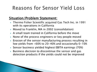
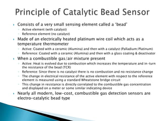
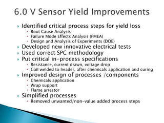
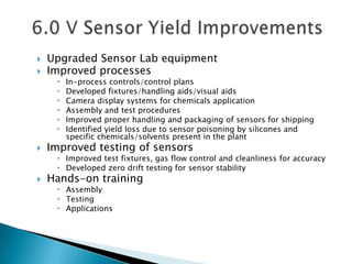
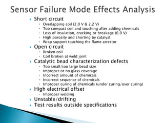
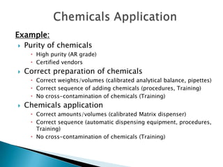
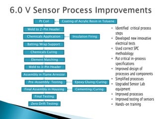
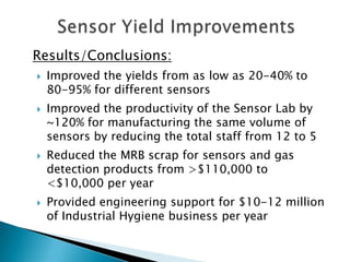
Dr. Rupendra M. Anklekar

  November 20, 2012
Situation/Problem Statement:
   Thermo Fisher Scientific acquired Gas Tech Inc. in 1991
    with its operations in California
   Moved to Franklin, MA in 2002 (consolidation)
   A small team trained in California before the move
   None of the process engineers or key people moved
   Erosion of the sensor manufacturing process resulting in
    low yields from ~60% to 20-40% and occasionally 0-10%
   Sensor business yielded highest EBITA earnings (70%)
   Business decision to discontinue the sensor and gas
    detection products if the yields could not be improved
Sensor Technologies:
   Catalytic Bead (Combustible gas)
   Electro-chemical (Toxic gas & Oxygen)
   Thermal Conductivity (TC)
   Infrared (IR)
   Semiconductor (SC)
   Photo-Ionization Detector (PID)
   Flame Ionization Detector (FID)
   Paper/Tape
   Principle of catalytic bead sensor
   Catalytic bead sensors
      Low Power – 2.0 V
      Medium Power – 2.2 V
      High Power – 6.0 V
   Catalytic bead sensor comparison
        Voltage/current/power
        Process equipment
        Platinum wire
        Chemicals used
        Chemicals application
        Application – Portable or Fixed System
   6.0 V sensor Yield improvement - Focus
   Consists of a very small sensing element called a ‘bead’
    ◦ Active element (with catalyst)
    ◦ Reference element (no catalyst)
   Made of an electrically heated platinum wire coil which acts as a
    temperature thermometer
    ◦ Active: Coated with a ceramic (Alumina) and then with a catalyst (Palladium/Platinum)
    ◦ Reference: Coated with a ceramic (Alumina) and then with a glass coating & deactivator
   When a combustible gas/air mixture present
    ◦ Active: Heat is evolved due to combustion which increases the temperature and in-turn
      the resistance of the bead (TCR)
    ◦ Reference: Since there is no catalyst there is no combustion and no resistance change
    ◦ The change in electrical resistance of the active element with respect to the reference
      element is measured using a standard Wheatstone bridge circuit
    ◦ This change in resistance is directly correlated to the combustible gas concentration
      and displayed on a meter or some similar indicating device
   Nearly all modern, low-cost, combustible gas detection sensors are
    electro-catalytic bead type
Property         2.0 Volt (Low)       2.2 Volt (Medium)           6.0 Volt (High)

   Voltage              2.0 V                  2.2 V                      6.0 V

   Current             91 mA                  142 mA                     242 mA

    Power              0.18 W                  0.31 W                    1.45 W

Platinum Wire           Bare                    Bare                 Alumina Coated

   Platinum       0.6 mils/15 µm Φ       1.2 mils/30 µm Φ           2.0 mils/50 µm Φ
   Alumina                                                      3.8-4.0 mils/95-100 µm Φ
Winder/Bonder      Semi-Automatic              Manual                    Manual
   Catalyst      Palladium + Platinum         Platinum                  Platinum
 Active Bead        40-46 Layers            20-28 Layers              18-26 Layers
Reference Bead      10-12 Layers            20-28 Layers              18-26 Layers
 Chemicals       Alumina Dispersion     Ceramic Former (30%)       Ceramic Former (70%)
 Application     Palladium Chloride     Glass Former Solution      Glass Former Solution
                  Platinum Chloride      Platinized Alumina     Platinum Chloride Solution
                                         Deactivator Solution       Deactivator Solution
 Application      Portables/Genesis       Portables/Innova            Fixed Systems
Innova                      Genesis

 Catalytic Bead Sensors                Portable Systems


Explosion-proof Housing   Polyester Housing     High Temperature Housing

                           Fixed Systems
6.0 V, 2-3 coatings
        Pt Coil             Coating of Acrylic Resin in Toluene
                                                                          20-30 min. drying

  Weld to 2-Pin Header
                                                          6.0 V, slow voltage ramping
 Chemicals Application                Insulation Firing   and soak for 1 hour

  Batting/Wrap Support

    Chemicals Curing         4 days

    Element Matching         Maximum 7 boards each of Active and Reference
                             elements and each board holding 14 elements
   Weld to 3-Pin Header

Assembly in Flame Arrestor

  Pre-Assembly Testing                 Epoxy Gluing/Curing        1 day

Final Assembly in Housing               Cementing/Curing        1 day

       Final Testing            Electrical Offset – 0 +/-20 mV, IP – 5.2-5.65 V
                                Response – 85-140 mV, Noise – </= 1 mV
    Zero Drift Testing    7-10 days
   Identified critical process steps for yield loss
      Root Cause Analysis
      Failure Mode Effects Analysis (FMEA)
      Design and Analysis of Experiments (DOE)
   Developed new innovative electrical tests
   Used correct SPC methodology
   Put critical in-process specifications
      Resistance, current drawn, voltage drop
      Coil welded to header, after chemicals application and curing
   Improved design of processes /components
      Chemicals application
      Wrap support
      Flame arrestor
   Simplified processes
      Removed unwanted/non-value added process steps
   Upgraded Sensor Lab equipment
   Improved processes
        In-process controls/control plans
        Developed fixtures/handling aids/visual aids
        Camera display systems for chemicals application
        Assembly and test procedures
        Improved proper handling and packaging of sensors for shipping
        Identified yield loss due to sensor poisoning by silicones and
         specific chemicals/solvents present in the plant
   Improved testing of sensors
      Improved test fixtures, gas flow control and cleanliness for accuracy
      Developed zero drift testing for sensor stability
   Hands-on training
      Assembly
      Testing
      Applications
   Short circuit
         Overlapping coil (2.0 V & 2.2 V)
         Too compact coil and touching after adding chemicals
         Loss of insulation, cracking or breakage (6.0 V)
         High porosity and shorting by catalyst
         Wrap support touching the flame arrestor
   Open circuit
       Broken coil
       Coil broken at weld joint
   Catalytic bead characterization defects
         Too small/too large bead size
         Improper or no glass coverage
         Incorrect amount of chemicals
         Incorrect sequence of chemicals
         Improper curing of chemicals (under curing/over curing)
   High electrical offset
       Improper welding
   Unstable/drifting
   Test results outside specifications
Example:
  Purity of chemicals
      High purity (AR grade)
      Certified vendors
   Correct preparation of chemicals
      Correct weights/volumes (calibrated analytical balance, pipettes)
      Correct sequence of adding chemicals (procedures, Training)
      No cross-contamination of chemicals (Training)
   Chemicals application
      Correct amounts/volumes (calibrated Matrix dispenser)
      Correct sequence (automatic dispensing equipment, procedures,
       Training)
      No cross-contamination of chemicals (Training)
Pt Coil          Coating of Acrylic Resin in Toluene

  Weld to 2-Pin Header

  Chemicals Application          Insulation Firing

  Batting/Wrap Support

    Chemicals Curing

    Element Matching

   Weld to 3-Pin Header

Assembly in Flame Arrestor

   Pre-Assembly Testing           Epoxy Gluing/Curing

Final Assembly in Housing          Cementing/Curing

      Final Testing

    Zero Drift Testing
Results/Conclusions:
   Improved the yields from as low as 20-40% to
    80-95% for different sensors
   Improved the productivity of the Sensor Lab by
    ~120% for manufacturing the same volume of
    sensors by reducing the total staff from 12 to 5
   Reduced the MRB scrap for sensors and gas
    detection products from >$110,000 to
    <$10,000 per year
   Provided engineering support for $10-12 million
    of Industrial Hygiene business per year
Fostered team work and team building
   Rupendra Anklekar – Senior Project Manager/Consultant / Sensor/
    Detector Scientist/Engineer / Senior Process Engineer
   Jeff Maybruck/Larry Fahey – Manufacturing Engineering Manager
   Mike Loncar - Production Manager
   Jayne Clarke - IH Value Stream Leader
   Van Krikorian/Mike Molinario - Supplier/Product Quality Engineer
   Brian Faulkner/Todd Muccini – Supply Chain/Materials Manager
   Aurora Norton/Jill Ligor – Buyer
   Diane Antosca – Planner
   Denise Whalen/Judith Lavelle - Production Supervisor
   Donna Lavelle/Clay Fournier/Maria Don Bourcier - Cell Leads
   Amy/Jane - Test Technicians
   Ying, Sophie, Air, Von, Noy, Sai, Seepan, Nog, Christe + 4 part-time
    operators - Assembly & Testing
   Open for discussion

Catalytic Bead Sensor Yield Improvement Presentation

  • 1.
    Dr. Rupendra M.Anklekar November 20, 2012
  • 2.
    Situation/Problem Statement:  Thermo Fisher Scientific acquired Gas Tech Inc. in 1991 with its operations in California  Moved to Franklin, MA in 2002 (consolidation)  A small team trained in California before the move  None of the process engineers or key people moved  Erosion of the sensor manufacturing process resulting in low yields from ~60% to 20-40% and occasionally 0-10%  Sensor business yielded highest EBITA earnings (70%)  Business decision to discontinue the sensor and gas detection products if the yields could not be improved
  • 3.
    Sensor Technologies:  Catalytic Bead (Combustible gas)  Electro-chemical (Toxic gas & Oxygen)  Thermal Conductivity (TC)  Infrared (IR)  Semiconductor (SC)  Photo-Ionization Detector (PID)  Flame Ionization Detector (FID)  Paper/Tape
  • 4.
    Principle of catalytic bead sensor  Catalytic bead sensors  Low Power – 2.0 V  Medium Power – 2.2 V  High Power – 6.0 V  Catalytic bead sensor comparison  Voltage/current/power  Process equipment  Platinum wire  Chemicals used  Chemicals application  Application – Portable or Fixed System  6.0 V sensor Yield improvement - Focus
  • 5.
    Consists of a very small sensing element called a ‘bead’ ◦ Active element (with catalyst) ◦ Reference element (no catalyst)  Made of an electrically heated platinum wire coil which acts as a temperature thermometer ◦ Active: Coated with a ceramic (Alumina) and then with a catalyst (Palladium/Platinum) ◦ Reference: Coated with a ceramic (Alumina) and then with a glass coating & deactivator  When a combustible gas/air mixture present ◦ Active: Heat is evolved due to combustion which increases the temperature and in-turn the resistance of the bead (TCR) ◦ Reference: Since there is no catalyst there is no combustion and no resistance change ◦ The change in electrical resistance of the active element with respect to the reference element is measured using a standard Wheatstone bridge circuit ◦ This change in resistance is directly correlated to the combustible gas concentration and displayed on a meter or some similar indicating device  Nearly all modern, low-cost, combustible gas detection sensors are electro-catalytic bead type
  • 6.
    Property 2.0 Volt (Low) 2.2 Volt (Medium) 6.0 Volt (High) Voltage 2.0 V 2.2 V 6.0 V Current 91 mA 142 mA 242 mA Power 0.18 W 0.31 W 1.45 W Platinum Wire Bare Bare Alumina Coated Platinum 0.6 mils/15 µm Φ 1.2 mils/30 µm Φ 2.0 mils/50 µm Φ Alumina 3.8-4.0 mils/95-100 µm Φ Winder/Bonder Semi-Automatic Manual Manual Catalyst Palladium + Platinum Platinum Platinum Active Bead 40-46 Layers 20-28 Layers 18-26 Layers Reference Bead 10-12 Layers 20-28 Layers 18-26 Layers Chemicals Alumina Dispersion Ceramic Former (30%) Ceramic Former (70%) Application Palladium Chloride Glass Former Solution Glass Former Solution Platinum Chloride Platinized Alumina Platinum Chloride Solution Deactivator Solution Deactivator Solution Application Portables/Genesis Portables/Innova Fixed Systems
  • 7.
    Innova Genesis Catalytic Bead Sensors Portable Systems Explosion-proof Housing Polyester Housing High Temperature Housing Fixed Systems
  • 8.
    6.0 V, 2-3coatings Pt Coil Coating of Acrylic Resin in Toluene 20-30 min. drying Weld to 2-Pin Header 6.0 V, slow voltage ramping Chemicals Application Insulation Firing and soak for 1 hour Batting/Wrap Support Chemicals Curing 4 days Element Matching Maximum 7 boards each of Active and Reference elements and each board holding 14 elements Weld to 3-Pin Header Assembly in Flame Arrestor Pre-Assembly Testing Epoxy Gluing/Curing 1 day Final Assembly in Housing Cementing/Curing 1 day Final Testing Electrical Offset – 0 +/-20 mV, IP – 5.2-5.65 V Response – 85-140 mV, Noise – </= 1 mV Zero Drift Testing 7-10 days
  • 9.
    Identified critical process steps for yield loss  Root Cause Analysis  Failure Mode Effects Analysis (FMEA)  Design and Analysis of Experiments (DOE)  Developed new innovative electrical tests  Used correct SPC methodology  Put critical in-process specifications  Resistance, current drawn, voltage drop  Coil welded to header, after chemicals application and curing  Improved design of processes /components  Chemicals application  Wrap support  Flame arrestor  Simplified processes  Removed unwanted/non-value added process steps
  • 10.
    Upgraded Sensor Lab equipment  Improved processes  In-process controls/control plans  Developed fixtures/handling aids/visual aids  Camera display systems for chemicals application  Assembly and test procedures  Improved proper handling and packaging of sensors for shipping  Identified yield loss due to sensor poisoning by silicones and specific chemicals/solvents present in the plant  Improved testing of sensors  Improved test fixtures, gas flow control and cleanliness for accuracy  Developed zero drift testing for sensor stability  Hands-on training  Assembly  Testing  Applications
  • 11.
    Short circuit  Overlapping coil (2.0 V & 2.2 V)  Too compact coil and touching after adding chemicals  Loss of insulation, cracking or breakage (6.0 V)  High porosity and shorting by catalyst  Wrap support touching the flame arrestor  Open circuit  Broken coil  Coil broken at weld joint  Catalytic bead characterization defects  Too small/too large bead size  Improper or no glass coverage  Incorrect amount of chemicals  Incorrect sequence of chemicals  Improper curing of chemicals (under curing/over curing)  High electrical offset  Improper welding  Unstable/drifting  Test results outside specifications
  • 12.
    Example:  Purityof chemicals  High purity (AR grade)  Certified vendors  Correct preparation of chemicals  Correct weights/volumes (calibrated analytical balance, pipettes)  Correct sequence of adding chemicals (procedures, Training)  No cross-contamination of chemicals (Training)  Chemicals application  Correct amounts/volumes (calibrated Matrix dispenser)  Correct sequence (automatic dispensing equipment, procedures, Training)  No cross-contamination of chemicals (Training)
  • 13.
    Pt Coil Coating of Acrylic Resin in Toluene Weld to 2-Pin Header Chemicals Application Insulation Firing Batting/Wrap Support Chemicals Curing Element Matching Weld to 3-Pin Header Assembly in Flame Arrestor Pre-Assembly Testing Epoxy Gluing/Curing Final Assembly in Housing Cementing/Curing Final Testing Zero Drift Testing
  • 14.
    Results/Conclusions:  Improved the yields from as low as 20-40% to 80-95% for different sensors  Improved the productivity of the Sensor Lab by ~120% for manufacturing the same volume of sensors by reducing the total staff from 12 to 5  Reduced the MRB scrap for sensors and gas detection products from >$110,000 to <$10,000 per year  Provided engineering support for $10-12 million of Industrial Hygiene business per year
  • 15.
    Fostered team workand team building  Rupendra Anklekar – Senior Project Manager/Consultant / Sensor/ Detector Scientist/Engineer / Senior Process Engineer  Jeff Maybruck/Larry Fahey – Manufacturing Engineering Manager  Mike Loncar - Production Manager  Jayne Clarke - IH Value Stream Leader  Van Krikorian/Mike Molinario - Supplier/Product Quality Engineer  Brian Faulkner/Todd Muccini – Supply Chain/Materials Manager  Aurora Norton/Jill Ligor – Buyer  Diane Antosca – Planner  Denise Whalen/Judith Lavelle - Production Supervisor  Donna Lavelle/Clay Fournier/Maria Don Bourcier - Cell Leads  Amy/Jane - Test Technicians  Ying, Sophie, Air, Von, Noy, Sai, Seepan, Nog, Christe + 4 part-time operators - Assembly & Testing
  • 16.
    Open for discussion