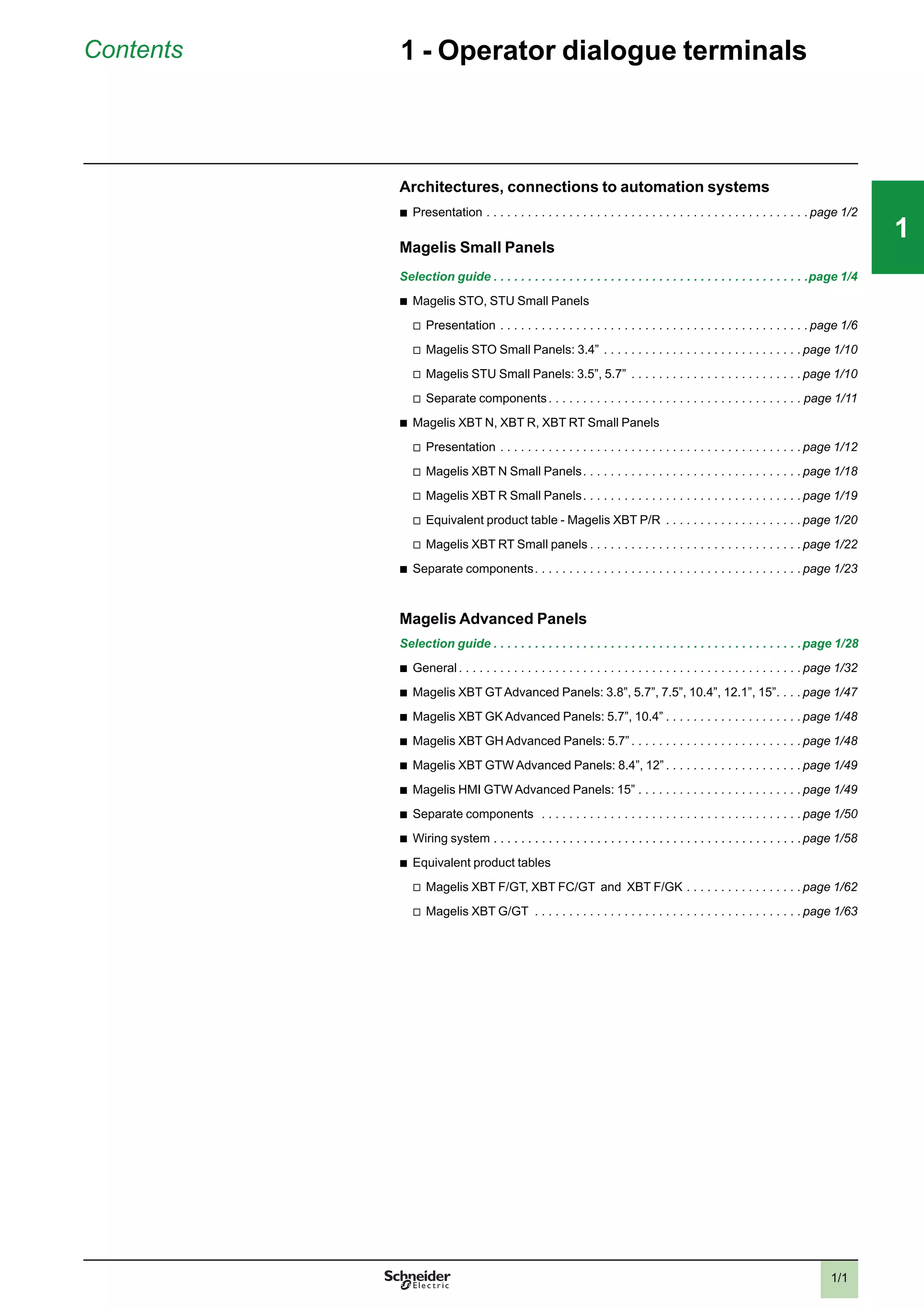
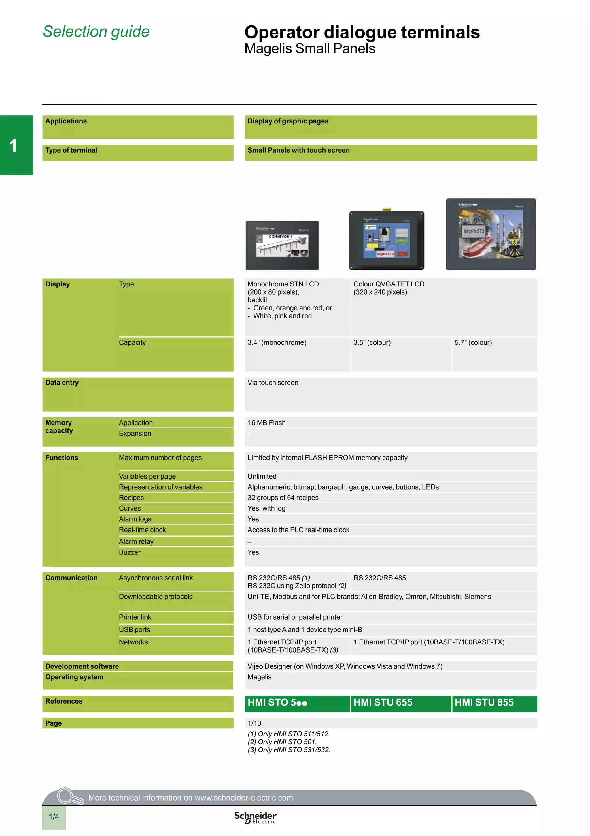
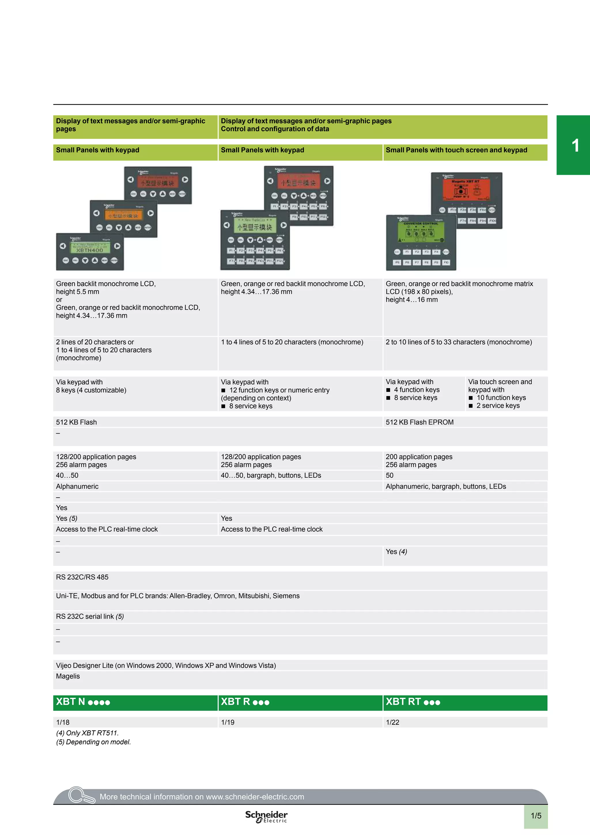
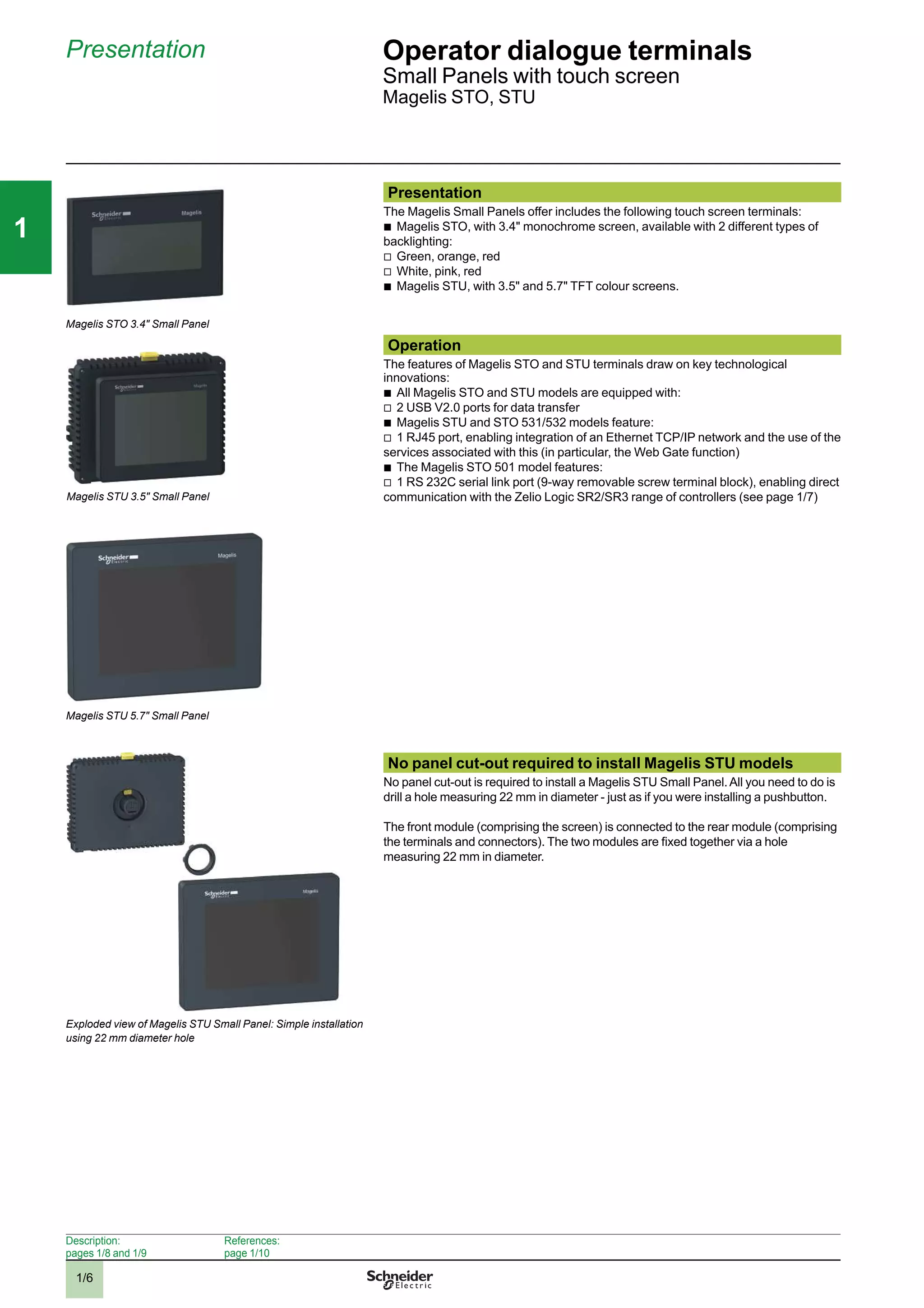
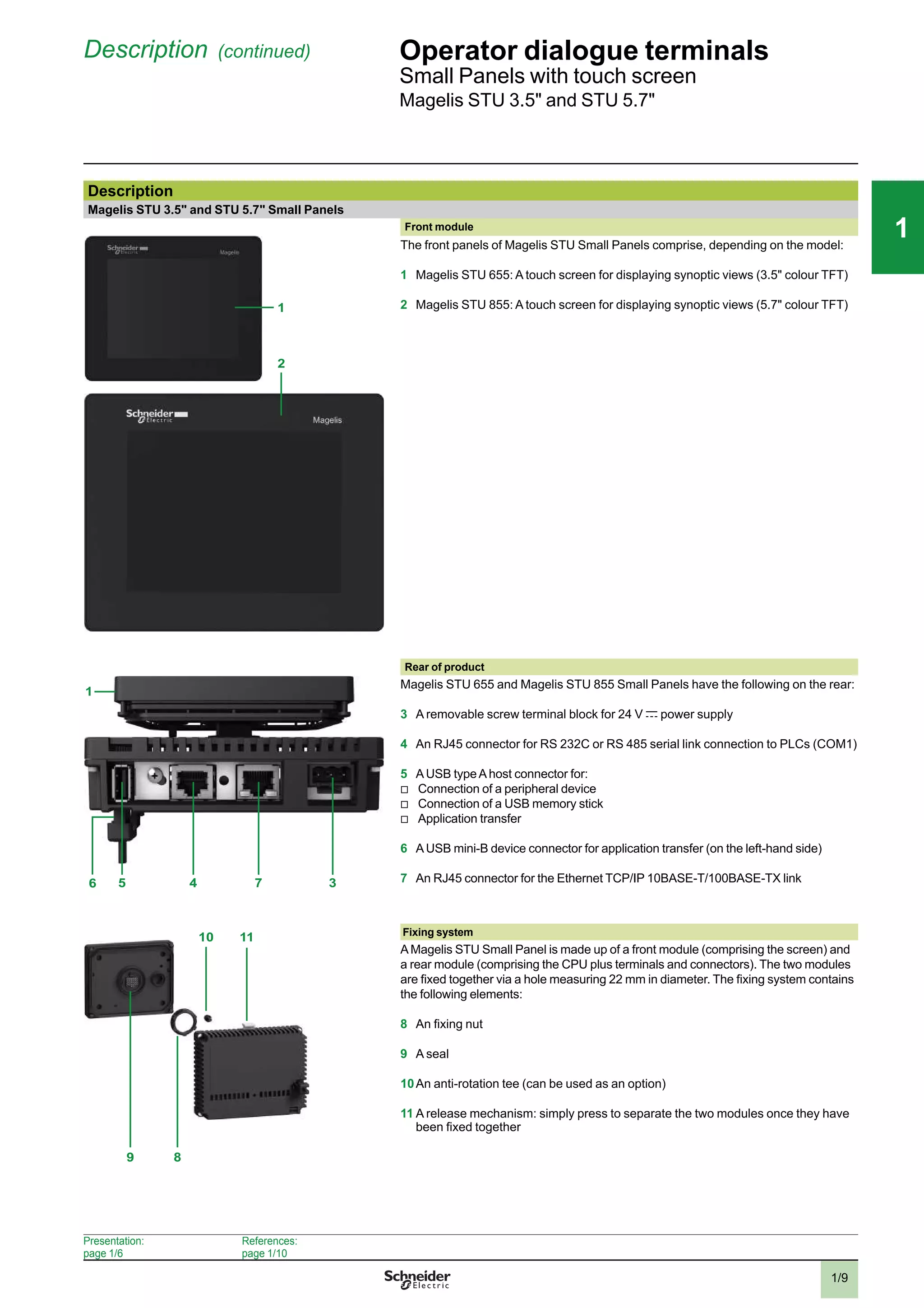
2
1
2
3
4
5
6
7
8
10
1
2
3
4
5
6
7
8
10
1
2
3
4
5
6
7
8
10
Human/Machine
Interfaces
Catalogue
2011
All technical information about products listed in
this catalogue are now available on:
www.schneider-electric.com
Browse the “product data sheet” to check out :
characteristics,
dimensions,
curves, ...
and also the links to the user guides and
the CAD files.
1 From the home page, type the model number* into the
“Search” box.
2 Under ”All” tab, click the model number that interests you.
* type the model
number without any
blank, replace “p
”
by “
*”
U
C
t1
G
R
t'1t2 t'2
U
C
t1
G
R
t'1t2 t'2
89,5
80
82
22,5
78
3 The product data sheet displays.
You can get this information in one single pdf file.
Discover this product
p
Characteritics
p
Functions
p
Connection
p
Dimensions
p
Download &
Documents
Other products
p
Help me to choose
Accessories
p
Plug
p
Sockets
Example : Zelio Time
data sheet
Example : Zelio Time
data sheet
Example : Zelio Time
data sheet
2
2
1
3
4
5
6
7
8
9
10
2
1
3
4
5
6
7
8
9
10
3
General contents Human/Machine Interfaces
1- Operator dialogue terminals
- Magelis Small Panels
- Magelis Advanced Panels
2- HMI Controllers
- Magelis HMI Controllers
- Magelis XBT GT/GK Advanced Panels with control function
- SoMachine
3- Industrial PCs
- PC Panels Magelis
- Magelis Flex PC BOX and Front Panels
- Magelis BOX PC
- Magelis iDisplay
4- HMI software
- Vijeo Designer Lite configuration software
- Vijeo Designer configuration software
5- Appendices
- Technical appendices
- Product references index
2
1
3
4
5
6
7
8
9
10
2
1
3
4
5
6
7
8
9
10
1/0
2
1
3
4
5
6
7
8
9
10
2
1
3
4
5
6
7
8
9
10
111
1/1
Contents 1 - Operator dialogue terminals
Architectures, connections to automation systems
b
Presentation . . . . . . . . . . . . . . . . . . . . . . . . . . . . . . . . . . . . . . . . . . . . . . . page 1/2
Magelis Small Panels
Selection guide . . . . . . . . . . . . . . . . . . . . . . . . . . . . . . . . . . . . . . . . . . . . . .page 1/4
b
Magelis STO, STU Small Panels
v
Presentation . . . . . . . . . . . . . . . . . . . . . . . . . . . . . . . . . . . . . . . . . . . . . page 1/6
v
Magelis STO Small Panels: 3.4” . . . . . . . . . . . . . . . . . . . . . . . . . . . . . page 1/10
v
Magelis STU Small Panels: 3.5”, 5.7” . . . . . . . . . . . . . . . . . . . . . . . . . page 1/10
v
Separate components . . . . . . . . . . . . . . . . . . . . . . . . . . . . . . . . . . . . . page 1/11
b
Magelis XBT N, XBT R, XBT RT Small Panels
v
Presentation . . . . . . . . . . . . . . . . . . . . . . . . . . . . . . . . . . . . . . . . . . . . page 1/12
v
Magelis XBT N Small Panels. . . . . . . . . . . . . . . . . . . . . . . . . . . . . . . . page 1/18
v
Magelis XBT R Small Panels. . . . . . . . . . . . . . . . . . . . . . . . . . . . . . . . page 1/19
v
Equivalent product table - Magelis XBT P/R . . . . . . . . . . . . . . . . . . . . page 1/20
v
Magelis XBT RT Small panels . . . . . . . . . . . . . . . . . . . . . . . . . . . . . . . page 1/22
b
Separate components. . . . . . . . . . . . . . . . . . . . . . . . . . . . . . . . . . . . . . . page 1/23
Magelis Advanced Panels
Selection guide . . . . . . . . . . . . . . . . . . . . . . . . . . . . . . . . . . . . . . . . . . . . .page 1/28
b
General . . . . . . . . . . . . . . . . . . . . . . . . . . . . . . . . . . . . . . . . . . . . . . . . . . page 1/32
b
Magelis XBT GTAdvanced Panels: 3.8”, 5.7”, 7.5”, 10.4”, 12.1”, 15”. . . . page 1/47
b
Magelis XBT GK Advanced Panels: 5.7”, 10.4” . . . . . . . . . . . . . . . . . . . . page 1/48
b
Magelis XBT GH Advanced Panels: 5.7” . . . . . . . . . . . . . . . . . . . . . . . . . page 1/48
b
Magelis XBT GTW Advanced Panels: 8.4”, 12” . . . . . . . . . . . . . . . . . . . . page 1/49
b
Magelis HMI GTW Advanced Panels: 15” . . . . . . . . . . . . . . . . . . . . . . . . page 1/49
b
Separate components . . . . . . . . . . . . . . . . . . . . . . . . . . . . . . . . . . . . . . page 1/50
b
Wiring system . . . . . . . . . . . . . . . . . . . . . . . . . . . . . . . . . . . . . . . . . . . . .page 1/58
b
Equivalent product tables
v
Magelis XBT F/GT, XBT FC/GT and XBT F/GK . . . . . . . . . . . . . . . . . page 1/62
v
Magelis XBT G/GT . . . . . . . . . . . . . . . . . . . . . . . . . . . . . . . . . . . . . . . page 1/63
2
1
3
4
5
6
7
8
9
10
2
1
3
4
5
6
7
8
9
10
111
1/2
111
Presentation Operator dialogue terminals
Architectures, connection to automation
systems
Examples of connectionsExamples of connections
Presentation
Magelis operator dialogue terminals communicate with automation system equipment:
b
Via serial link
b
By means of integration into an Ethernet TCP/IP architecture
Communication via serial link
Twido
XBTN
Modicon M 340
Modicon M238
Modbus
XBTGK
XBTGT
Quantum
Modbus
STO
STU
All Magelis terminals feature an integrated RS 232 C or
RS 422/485 asynchronous serial link.
Use of the Uni-TE or Modbus protocol makes it easy to
set up communication with Schneider Electric PLCs.
Third-party protocols enable connection to PLCs offered
by major manufacturers on the market:
b
DF1, DH485 for Allen-Bradley PLCs
b
SysmacWay for Omron PLCs
b
MPI/PPI for Siemens Simatic S7 PLCs
b
Mitsubishi Melsec FX PLC
2
3
4
5
6
7
8
9
10
2
3
4
5
6
7
8
9
10
1/3
111
Presentation (continued) Operator dialogue terminals 1
Architectures, connection to automation
systems
Presentation (continued)
Integration into an architecture with Ethernet TCP/IP network
XBT GK
STU
XBT GT
Web GateXBT GTW
Premium
ATV 71
Ethernet TCP/IP
XBT GK
XBT GH
XBT GT
TSX MicroTwido
Modicon STB
@
Automation platforms provide transparent routing of
Uni-TE or Modbus messages from a TCP/IP network to a
Uni-TE or Modbus network and vice versa.
The various services offered for the terminals are:
b
Modbus TCP/IP messaging (for XBT GT, XBT GK,
XBT GH and XBT GTW, access with Ethernet TCP/IP
Modbus protocol)
b
Browse function with XBT GTW or standard PC
b
Web Gate function: Diagnostics to remotely control
the application
b
FTP server: Transfer of data files with the terminal
b
Data Sharing function: Data exchange on Ethernet
between 8 terminals (maximum)
b
E-mail function
2
3
4
5
6
7
8
9
10
2
3
4
5
6
7
8
9
10
1/4
111
Selection guide Operator dialogue terminals
Magelis Small Panels
Applications Display of graphic pages
Type of terminal Small Panels with touch screen
Display Type Monochrome STN LCD
(200 x 80 pixels),
backlit
- Green, orange and red, or
- White, pink and red
Colour QVGATFT LCD
(320 x 240 pixels)
Capacity 3.4" (monochrome) 3.5" (colour) 5.7" (colour)
Data entry Via touch screen
Memory
capacity
Application 16 MB Flash
Expansion –
Functions Maximum number of pages Limited by internal FLASH EPROM memory capacity
Variables per page Unlimited
Representation of variables Alphanumeric, bitmap, bargraph, gauge, curves, buttons, LEDs
Recipes 32 groups of 64 recipes
Curves Yes, with log
Alarm logs Yes
Real-time clock Access to the PLC real-time clock
Alarm relay –
Buzzer Yes
Communication Asynchronous serial link RS 232C/RS 485 (1)
RS 232C using Zelio protocol (2)
RS 232C/RS 485
Downloadable protocols Uni-TE, Modbus and for PLC brands: Allen-Bradley, Omron, Mitsubishi, Siemens
Printer link USB for serial or parallel printer
USB ports 1 host type A and 1 device type mini-B
Networks 1 Ethernet TCP/IP port
(10BASE-T/100BASE-TX) (3)
1 Ethernet TCP/IP port (10BASE-T/100BASE-TX)
Development software Vijeo Designer (on Windows XP, Windows Vista and Windows 7)
Operating system Magelis
References HMI STO 5p p HMI STU 655 HMI STU 855
Page 1/10
(1) Only HMI STO 511/512.
(2) Only HMI STO 501.
(3) Only HMI STO 531/532.
1/5
111
Display of text messages and/or semi-graphic
pages
Display of text messages and/or semi-graphic pages
Control and configuration of data
Small Panels with keypad Small Panels with keypad Small Panels with touch screen and keypad
Green backlit monochrome LCD,
height 5.5 mm
or
Green, orange or red backlit monochrome LCD,
height 4.34…17.36 mm
Green, orange or red backlit monochrome LCD,
height 4.34…17.36 mm
Green, orange or red backlit monochrome matrix
LCD (198 x 80 pixels),
height 4…16 mm
2 lines of 20 characters or
1 to 4 lines of 5 to 20 characters
(monochrome)
1 to 4 lines of 5 to 20 characters (monochrome) 2 to 10 lines of 5 to 33 characters (monochrome)
Via keypad with
8 keys (4 customizable)
Via keypad with
b
12 function keys or numeric entry
(depending on context)
b
8 service keys
Via keypad with
b
4 function keys
b
8 service keys
Via touch screen and
keypad with
b
10 function keys
b
2 service keys
512 KB Flash 512 KB Flash EPROM
–
128/200 application pages
256 alarm pages
128/200 application pages
256 alarm pages
200 application pages
256 alarm pages
40…50 40…50, bargraph, buttons, LEDs 50
Alphanumeric Alphanumeric, bargraph, buttons, LEDs
–
Yes
Yes (5) Yes
Access to the PLC real-time clock Access to the PLC real-time clock
–
– Yes (4)
RS 232C/RS 485
Uni-TE, Modbus and for PLC brands: Allen-Bradley, Omron, Mitsubishi, Siemens
RS 232C serial link (5)
–
–
Vijeo Designer Lite (on Windows 2000, Windows XP and Windows Vista)
Magelis
XBT N p p p p XBT R p p p XBT RT p p p
1/18 1/19 1/22
(4) Only XBT RT511.
(5) Depending on model.
1/6
111
Presentation Operator dialogue terminals 1
Small Panels with touch screen
Magelis STO, STU
Presentation
The Magelis Small Panels offer includes the following touch screen terminals:
b
Magelis STO, with 3.4" monochrome screen, available with 2 different types of
backlighting:
v
Green, orange, red
v
White, pink, red
b
Magelis STU, with 3.5" and 5.7" TFT colour screens.
Operation
The features of Magelis STO and STU terminals draw on key technological
innovations:
b
All Magelis STO and STU models are equipped with:
v
2 USB V2.0 ports for data transfer
b
Magelis STU and STO 531/532 models feature:
v
1 RJ45 port, enabling integration of an Ethernet TCP/IP network and the use of the
services associated with this (in particular, the Web Gate function)
b
The Magelis STO 501 model features:
v
1 RS 232C serial link port (9-way removable screw terminal block), enabling direct
communication with the Zelio Logic SR2/SR3 range of controllers (see page 1/7)
No panel cut-out required to install Magelis STU models
No panel cut-out is required to install a Magelis STU Small Panel.All you need to do is
drill a hole measuring 22 mm in diameter - just as if you were installing a pushbutton.
The front module (comprising the screen) is connected to the rear module (comprising
the terminals and connectors). The two modules are fixed together via a hole
measuring 22 mm in diameter.
Magelis STO 3.4" Small Panel
Exploded view of Magelis STU Small Panel: Simple installation
using 22 mm diameter hole
Description:
pages 1/8 and 1/9
References:
page 1/10
Magelis STU 5.7" Small Panel
Magelis STU 3.5" Small Panel
2
3
4
5
6
7
8
9
10
2
3
4
5
6
7
8
9
10
1/7
111
Presentation (continued) Operator dialogue terminals 1
Small Panels with touch screen
Magelis STO, STU
Configuration
Magelis STO/STU terminals can be configured using Vijeo Designer software in a
Windows XP, Windows Vista or Windows 7 environment.
Vijeo Designer software boasts an advanced user interface with many configurable
windows, enabling operator dialogue projects to be developed quickly and easily.
See page 4/8.
Communication
Magelis STO/STU terminals communicate with PLCs via an integrated serial link,
using the following communication protocols:
b
Schneider Electric (Uni-TE, Modbus)
b
Third-party: Mitsubishi Electric, Omron, Allen-Bradley and Siemens
The Magelis STO 501 terminal is dedicated exclusively to communication with Zelio
Logic SR2/SR3 range controllers.
It communicates with these controllers via a direct connection cable SR2 CBL 09
(see page 1/25) , using Zelio protocol, which is included in Vijeo Designer V6.0.
Magelis STU and STO 531/532 terminals are connected on Ethernet TCP/IP
networks via Modbus TCP or a third-party protocol.
Display of a video sequence
Ethernet TCP/IP
CANopen
Premium
Modicon M340
Modicon STB
ATV 71
Modicon M340
Modbus / Uni-TelwayTwido
STU
STO
STO 531/532
STU
WEB GATE
Description:
pages 1/8 and 1/9
References:
page 1/10
Example of serial link architecture
Example of Ethernet TCP/IP network architecture
2
3
4
5
6
7
8
9
10
2
3
4
5
6
7
8
9
10
1/8
111
Description
Magelis STO 3.4" Small Panels
Front panel
The front panels of Magelis STO Small Panels comprise:
1 A touch screen for displaying synoptic views (3.4" backlit monochrome) with:
v
Green, orange or red backlighting for STO 511, STO 531 and STO 501 terminals
v
White orange or red backlighting for STO 512 and STO 532 terminals
Rear panel
Magelis STO Small Panelshave the following on the rear panel:
1 A removable screw terminal block for 24 V c power supply
2 A connector for connecting to PLCs or controllers, depending on the terminal
model:
v
Magelis STO 511/ 512: An RJ45 (COM1) connector for RS 232C or RS 485 serial
link
v
Magelis STO 531/532: An RJ45 (ETHERNET) connector for Ethernet 10BASE-T/
100BASE-TX link
v
Magelis STO 501: A 9-way removable screw terminal block (COM1) for RS 232C
serial link using Zelio protocol
3 AUSB typeAhost connector for:
v
Connection of a peripheral device
v
Connection of a USB memory stick
v
Application transfer
4 AUSB mini-B device connector for application transfer
Presentation:
page 1/6
References:
page 1/10
Operator dialogue terminals 1
Small Panels with touch screen
Magelis STO 3.4"
Description
1
1 2 4 3
Magelis STO 511/512/531/532 Small Panels
Magelis STO 501 Small Panel
1 4 32
2
3
4
5
6
7
8
9
10
2
3
4
5
6
7
8
9
10
1/9
111
Operator dialogue terminals 1
Small Panels with touch screen
Magelis STU 3.5" and STU 5.7"
Description (continued)
Description
Magelis STU 3.5" and STU 5.7" Small Panels
Front module
1
2
The front panels of Magelis STU Small Panels comprise, depending on the model:
1 Magelis STU 655: A touch screen for displaying synoptic views (3.5" colour TFT)
2 Magelis STU 855: A touch screen for displaying synoptic views (5.7" colour TFT)
37456
1
Rear of product
Magelis STU 655 and Magelis STU 855 Small Panels have the following on the rear:
3 A removable screw terminal block for 24 V c power supply
4 An RJ45 connector for RS 232C or RS 485 serial link connection to PLCs (COM1)
5 AUSB typeAhost connector for:
v
Connection of a peripheral device
v
Connection of a USB memory stick
v
Application transfer
6 AUSB mini-B device connector for application transfer (on the left-hand side)
7 An RJ45 connector for the Ethernet TCP/IP 10BASE-T/100BASE-TX link
11
8
10
9
Fixing system
AMagelis STU Small Panel is made up of a front module (comprising the screen) and
a rear module (comprising the CPU plus terminals and connectors). The two modules
are fixed together via a hole measuring 22 mm in diameter. The fixing system contains
the following elements:
8 An fixing nut
9 A seal
10An anti-rotation tee (can be used as an option)
11 A release mechanism: simply press to separate the two modules once they have
been fixed together
Presentation:
page 1/6
References:
page 1/10
2
3
4
5
6
7
8
9
10
2
3
4
5
6
7
8
9
10
1/10
111
Operator dialogue terminals
Small Panels with touch screen
Magelis STO, STU
References
Magelis STO monochrome touch screen terminals
3.4" screen
Type of screen Number of ports Application
memory
capacity
Compact Flash
memory
Embedded
Ethernet
Reference Weight
kg
STN
Green, orange, red
1 COM1 (1)
2 USB
16 MB No – HMI STO 511 1.000
1 ETHERNET (2)
2 USB
16 MB No 1 HMI STO 531 1.000
STN
White, pink, red
1 COM1 (1)
2 USB
16 MB No – HMI STO 512 1.000
1 ETHERNET (2)
2 USB
16 MB No 1 HMI STO 532 1.000
STN
Green, orange, red
1 COM1 (1)
2 USB
16 MB No – HMI STO 501 1.000
Magelis STU colour touch screen terminals
Type of screen Number of ports Application
memory
capacity
Compact Flash
memory
Embedded
Ethernet
Reference Weight
kg
3.5" screen
TFT 1 COM1 (1)
1 ETHERNET (2)
2 USB
16 MB No 1 HMI STU 655 1.000
5.7" screen
TFT 1 COM1 (1)
1 ETHERNET (2)
2 USB
16 MB No 1 HMI STU 855 –
Software
Configuration software
Description Operating system Reference Weight
kg
Vijeo Designer Windows XP Professional (32-bit)
Windows Vista (32-bit)
Windows 7 (32-bit)
See page 4/13 –
(1) RS 232C or RS 485 serial link.
(2) Ethernet 10BASE-T/100BASE-TX link.
(3) RS 232C serial link using Zelio protocol, for direct connection to Zelio Logic SR2/SR3 controllers.
Presentation:
page 1/6
Description:
pages 1/8 to 1/9
HMI STO 511
HMI STU 655
HMI STU 855
2
3
4
5
6
7
8
9
10
2
3
4
5
6
7
8
9
10
1/11
111
Operator dialogue terminals
Small Panels with touch screen
Magelis STO, STU
References (continued)
Separate components (1)
Description Description/function Compatible with Reference Weight
kg
Accessories kit Contains:
b
An anti-rotation tee
b
A USB A type clip
b
A USB mini-B type clip
b
An adaptor panel for mounting on an
enclosure of 1 mm in thickness
HMI STU 655
HMI STU 855
HMIZSUKIT –
Protective sheets 5 peel-off sheets for protecting the screen HMI STO 5p p HMIZS60 –
HMI STU 655 HMIZS61 –
HMI STU 855 HMIZS62 –
USB clip Holds the USB A type connection in place HMI STO 5p p HMIZSCLP1 –
Holds the USB mini-B type connection
in place
HMI STO 5p p HMIZSCLP3 –
Replacement parts (2)
Description Description/function Compatible with Reference Weight
kg
Nuts Set of 10 nuts, 22 mm
(front module of the HMI STU is
fixed to the enclosure using a 22 mm nut
(see page 1/6))
HMI STU 655
HMI STU 855
ZB5AZ901 –
Bezel key Enables the fixing nut to be tightened HMI STU 655
HMI STU 855
ZB5AZ905 –
Seal Dust and damp proofs the connection
between the front and rear modules of the
HMI STO 5p p
HMI STO 5p p HMIZS50 –
(1) Non-exhaustive list: other separate components are listed on pages 1/24 onwards.
(2) Non-exhaustive list: other replacement parts are listed on page 1/24.
Presentation:
page 1/6
Description:
pages 1/8 and 1/9
2
3
4
5
6
7
8
9
10
2
3
4
5
6
7
8
9
10
1/12
111
Presentation Operator dialogue terminals
Magelis XBT N, XBT R Small Panels with
keypad,
Magelis XBT RT Small Panels with touch screen
and keypad
Presentation
XBT R411 XBT N400 XBT RT511
Magelis XBT N and Magelis XBT R/RT terminals are
used to display messages and variables.
In addition, Magelis terminals XBT RT can display
small graphic elements.
The various keys can be used to:
b
Modify variables
b
Control a device
b
Navigate within the operator dialogue application
On XBT RT terminals, the touch screen can also be
used to modify variables, control devices and navigate
within the dialogue application.
Alarm messages can be printed out from models that
have a printer port.
Operation
All Magelis terminals have the same user interface:
b
A configurable touch screen, on XBT RT only
(“touch-sensitive” mode)
b
2 service keys ( , ) configurable for contextual
link or control, on XBT N/R and XBT RT
(“entry”/“control” modes)
b
2 service keys (ESC, ENTER), non-configurable
b
These keys are complemented by:
v
On XBT N terminals: 4 customizable service keys
which can be configured as function keys (“control”
mode) or service keys (“entry” mode)
v
On XBT R terminals: 4 service keys, non-
configurable, and 12 function or numeric entry keys
(depending on context)
v
On XBT RT terminals in “control” or “entry” mode:
4 customizable and configurable function keys
4 service keys (non-configurable)
“Entry” customization
“Control” customization
Description:
pages 1/15 to 1/17
References:
pages 1/18, 1/19 and 1/22
2
3
4
5
6
7
8
9
10
2
3
4
5
6
7
8
9
10
1/13
111
Presentation (continued) Operator dialogue terminals
Magelis XBT N, XBT R Small Panels with
keypad,
Magelis XBT RT Small Panels with touch screen
and keypad
Configuration
Magelis terminals can be configured using Vijeo
Designer Lite software in a Windows environment.
Vijeo Designer Lite software uses the concept of
pages: each page can be viewed in its entirety.
A 2, 4 or 10-line window, depending on the terminal
model to be configured, is used to view the screen of
this virtual terminal.
The symbol databases of TwidoSoft, PL7 and Concept
applications can be imported into the Vijeo Designer
Lite operator dialogue application.
See page 4/4.
Communication
XBT N and XBT R/RT terminals communicate with
PLCs via an integrated serial link in either point-to-
point or multidrop mode, depending on the model.
The communication protocols used are those of
Schneider Electric PLCs (Uni-TE, Modbus) and those
of the main manufacturers on the market.
XBT N401, XBT R411 and XBT RT 511 terminals
communicate with Zelio Logic smart relays via a direct
connection cable and using the Zelio protocol, which is
included in Vijeo Designer Lite V1.3.
Vijeo Designer Lite
Twido
programmable
controller
XBT N terminal
XBT N terminal
Zelio Logic
smart relay
Connection example with Zelio Logic smart relay
Connection example with Twido programmable
controller
Description:
pages 1/15 to 1/17
References:
pages 1/18, 1/19 and 1/22
2
3
4
5
6
7
8
9
10
2
3
4
5
6
7
8
9
10
1/14
111
Functions Operator dialogue terminals
Magelis XBT N, XBT R Small Panels with
keypad,
Magelis XBT RT Small Panels with touch screen
and keypad
Functions
On their front panel, XBT N/R/RT terminals have function keys and service keys
(depending on how the keys have been configured for “control” and “entry” modes).
XBT RT terminals feature a touch screen which can be configured in “touch-
sensitive” operating mode.
“F” function keys
The function keys are defined for the whole application.
The number of function keys depends on the model:
b
F1, F2, F3, F4 on XBT N
b
F1…F12 on XBT R
b
F1…F10 or F1...F4 according to configuration on XBT RT
They can have the following functions:
b
Accessing a page
b
Impulse command
b
“Toggle” command
b
...
In addition, with the XBT R terminal, if the MOD key is pressed, the 12 function keys
become numeric entry keys 1…0, +/- and ..
“R” function keys for XBT RT (“entry” mode)
The R1, R2, R3 and R4 function keys on the XBT RT are defined for the pages
displayed. They can be used for:
b
Accessing a page
b
Memorising memory bits
b
Toggling memory bits (ON/OFF)
b
Resetting memory bits to 1/0
An icon can be displayed on the screen, above the Ri keys. This icon is defined
using the Vijeo Designer Lite software.
Matrix touch screen (5 x 11 cells) for XBT RT
The touch screen can be configured to be active on XBT RT (“touch-sensitive” mode).
This is used for:
b
Accessing a page
b
Memorising/toggling memory bits
b
Modifying a numeric field via a virtual numeric keypad
Service keys
Service keys , ESC, DEL, , , MOD, ENTER and are used to modify the
parameters of the automation system.
They perform the following actions:
ESC Cancel an entry, suspend or stop a current action, go up one level in a menu
DEL Delete the character selected in entry mode
MOD Select the variable field in which to enter data. Enable entry in the next field,
on each press, from left to right and top to bottom.
ENTER Confirm a selection or entry, acknowledge an alarm
The “arrow” keys are used to:
v
Change the page within a menu
v
Display the current alarms
v
Change a digit in a variable field in which data is being entered
v
Activate the function associated with a functional link
v
Move up and down within a page (XBT N40p )
v
Select the value of a digit
v
Select a value from a list of choices
v
Increment or decrement the value of a variable field
Description:
pages 1/15 to 1/17
References:
pages 1/18, 1/19 and 1/22
2
3
4
5
6
7
8
9
10
2
3
4
5
6
7
8
9
10
1/15
111
Description Operator dialogue terminals
Magelis XBT N Small Panels with keypad
Description of XBT N terminals
XBT N terminals comprise:
On the front panel
1 A communication monitoring lamp (model XBT N401)
2 A backlit ultra-bright LCD display: 122 x 32 pixels (matrix) or 2 lines of
20 characters (alphanumeric)
3 Two non-customizable command or contextual link keys
4 An “alarm” LED (model XBT N401)
5 Six service keys, four of which (framed) can be configured as function keys and
customized using labels
6 Two system LEDs in entry mode or four LEDs that can be controlled by the PLC in
control mode (model XBT N401)
Supplied separately
b
A sheet of labels comprising:
7 An “entry” label
8 A “control” label (F1, F2, F3 and F4)
9 Four customizable blank labels
b
Two spring clips for fixing the terminal on the panel
On the rear panel
XBT N200/N400 terminals
1 An RJ45 connector for point-to-point serial link and connection for 5 V c power
supply (supplied by PLC)
XBT N401/N410/NU400 terminals
2 A removable screw terminal block for 24 V c external power supply
3 A 25-way female SUB-D connector for multidrop serial link
4 An 8-way female mini-DIN connector for serial printer link (model XBT N401)
2
3
5
3
2
5
1
4
XBT N401
XBT N200
6
7
8
9
1
2
3 4
XBT N200
XBT N401
Presentation:
pages 1/12 and 1/13
References:
page 1/18
2
3
4
5
6
7
8
9
10
2
3
4
5
6
7
8
9
10
1/16
111
Description (continued) Operator dialogue terminals
Magelis XBT R Small Panels with keypad
Description of XBT R terminals with keypad
XBT R terminals comprise:
On the front panel:
1 A communication monitoring LED (model XBT R411)
2 A backlit ultra-bright LCD display: 122 x 32 pixels (matrix)
3 Two non-customizable command or contextual link keys
4 An “alarm” lamp (model XBT R411)
5 Six service keys
6 Two system LEDs (model XBT R411)
7 Twelve function or numeric entry keys (depending on context), customizable
using labels
8 Twelve lamps (for model XBT R411), that can be controlled by the PLC
Supplied separately:
b
A sheet of labels comprising:
9 A “control” label (F1...F12)
10Two customizable blank labels
b
Four spring clips for fixing the terminal on the panel
On the rear panel
XBT R400 terminals
1 An RJ45 connector for point-to-point serial link and connection for 5 V c power
supply (supplied by PLC)
XBT R410/R411 terminals
2 A removable screw terminal block for 24 V c external power supply
3 A 25-way female SUB-D connector for multidrop serial link
4 An 8-way female mini-DIN connector for serial printer link (model XBT R411)
2
3
5
7
1
8
2 6
3
5
7
4
XBT R400
XBT R411
9
10
1
2
3 4
XBT R400
XBT R411
Presentation:
pages 1/12 and 1/13
References:
page 1/19
2
3
4
5
6
7
8
9
10
2
3
4
5
6
7
8
9
10
1/17
111
Description (continued) Operator dialogue terminals
Magelis XBT RT Small Panels with touch screen
and keypad
Description of XBT RT terminals with touch screen and keypad
XBT RT terminals comprise:
On the front panel:
XBT RT terminals
1 An ultra-bright backlit LCD display: 198 x 80 pixels (matrix)
2 Two service keys
3 Function or service keys which can be configured and customized using labels
4 Matrix touch screen (11 x 5 cells)
XBT RT511 terminal
5 A communication monitoring LED
6 A “touch panel or keys being pressed” LED
7 An “alarm” LED
8 Six or ten lamps, depending on the configuration, that can be controlled by the
PLC
Supplied separately:
b
2 sheets of labels comprising:
9 A configurable “control” label (F1…F4)
10A customizable blank “control” label
11 An “entry” label (R1…R4)
12A “touch-sensitive” label (F1…F10)
13Two customizable blank “touch-sensitive” labels
On the rear panel
XBT RT500 terminal
1 An RJ45 connector for point-to-point serial link and connection for 5 V c power
supply (supplied by PLC)
XBT RT511 terminal
2 A removable screw terminal block for 24 V c external power supply
3 An RJ45 connector for multidrop serial link
4 An 8-way female mini-DIN connector for serial printer link
1
2
3
XBT RT 500
4
XBT RT511
5
6
7
8
9
10
11
12
13
1
XBT RT500
XBT RT511
4
3
2
Presentation:
pages 1/12 and 1/13
References:
page 1/22
2
3
4
5
6
7
8
9
10
2
3
4
5
6
7
8
9
10
1/18
111
References Operator dialogue terminals
Small Panels with keypad
Magelis XBT N
Magelis XBT N Small Panels
Downloadable exchange
protocol
Compatible PLCs Supply voltage Type of screen Reference Weight
kg
Terminal with 2 lines of 20 characters (with alphanumeric screen)
Uni-TE, Modbus Twido, Nano, TSX Micro,
Premium, Modicon M340
5 V c via PLC
terminal port
Green backlit LCD XBT N200 0.360
Terminals with 4 lines of 20 characters (with matrix screen)
Uni-TE, Modbus Twido, Nano, TSX Micro,
Premium, Modicon M340
5 V c via PLC
terminal port
Green backlit LCD
(122 x 32 pixels)
XBT N400 0.360
Twido (1), Nano, TSX Micro,
Premium, TSX series 7,
Momentum, Quantum
Other Modbus slave devices,
Modicon M340
24 V c external
supply
Green backlit LCD
(122 x 32 pixels)
XBT N410 0.380
Uni-TE, Modbus Twido (1), Nano, TSX Micro,
Premium, TSX series 7,
Momentum, Quantum
Other Modbus slave devices,
Modicon M340
24 V c external
supply
Green, orange and
red backlit LCD (2)
(122 x 32 pixels)
XBT N401 0.380
Zelio Zelio Logic
Modbus TeSys model U motor starters
(3)
Altivar drives
24 V c external
supply
Green backlit LCD
(122 x 32 pixels)
XBT NU400 0.380
Software
Description Operating system Reference
Configuration software
Vijeo Designer Lite
Windows 2000, XP and Vista See page 4/7 –
Accessories (4)
Description Details For use with Reference Weight
kg
Accessory for flush
mounting
Kit for applications requiring a higher degree of
protection
or customization of the control desk, using flat
inner insulation (not included)
All XBT N XBT ZN01 –
Protective sheets 10 peel-off sheets All XBT N XBT ZN02 –
Sheets of re-usable labels 10 sheets of 6 labels XBT N200/400 XBL YN00 –
XBT N401
XBT NU400
XBL YN01 –
Mechanical adaptors for
substitution of XBT H
From XBT H0p 2p 1/H0p 1010 to XBT N410
From XBT H811050 to XBT N410
– XBT ZNCO –
Connection cables and accessories (5)
Description Compatibility Types of
connector
Physical
link
Protocol Length Reference Weight
kg
Adaptor cable XBT N200
XBT N400 (6)
RJ45-RJ45 RS 232C
RS 485
Modbus,
Uni-TE
0.1 m XBT ZN999 –
(1) Connection via integrated port or optional serial port on the Twido programmable controller.
(2) Also available with 4 signalling LEDs.
(3) Factory preloaded application for monitoring, diagnostics and adjustment of
1 to 8 TeSys model U motor starters.
(4) For other accessories, see page 1/24.
(5) For other connection cables and accessories, see pages 1/24 to 1/27.
(6) Adaptor XBT ZN999 is designed for use with XBT N200/N400 terminals (new version) and
cable XBT Z978 (replaced by XBT Z9780), or with XBT N200/N400 terminals (old version)
and the new XBT Z9780 cable.
Note: The new version of the XBT N terminal can be distinguished from the old version by its exterior,
as it features the Schneider Electric logo on the front panel (on the left above the screen).
ESC
DEL
MOD
XBT ZN01
521377
ENTER
ESC
DEL
MOD ENTER
ESC
DEL
MOD
XBT ZN02
521373
XBT N200
XBT N400/N410/NU400
XBT N401
Presentation:
pages 1/12 and 1/13
Description:
page 1/15
2
3
4
5
6
7
8
9
10
2
3
4
5
6
7
8
9
10
1/19
111
References (continued) Operator dialogue terminals
Small Panels with keypad
Magelis XBT R
Magelis XBT R Small Panels
Downloadable exchange
protocol
Compatible PLCs Supply voltage Type of screen Reference Weight
kg
Terminals with 4 lines of 20 characters (with matrix screen)
Uni-TE, Modbus Twido, Nano, TSX Micro,
Premium, Modicon M340
5 V c via PLC
terminal port
Green backlit
LCD
(122 x 32 pixels)
XBT R400 0.550
Twido (1), Nano, TSX Micro,
Premium, TSX series 7,
Momentum, Quantum
Other Modbus slave devices,
Modicon M340
24 V c external
supply
Green backlit
LCD
(122 x 32 pixels)
XBT R410 0.550
Uni-TE, Modbus Twido (1), Nano, TSX Micro,
Premium, TSX series 7,
Momentum, Quantum
Other Modbus slave devices,
Modicon M340
24 V c external
supply
Green, orange
and red backlit
LCD (2)
(122 x 32 pixels)
XBT R411 0.550
Zelio Zelio Logic
Software
Description Operating system Reference
Configuration software
Vijeo Designer Lite
Windows 2000, XP and Vista See page 4/7 –
Accessories (3)
Description Details For use with Reference Weight
kg
Accessory for flush
mounting
Kit for applications requiring a higher degree of
protection
or customization of the control desk, using flat
inner insulation (not included)
All XBT R XBT ZR01 –
Protective sheets 10 peel-off sheets All XBT R XBT ZR02 –
Sheets of re-usable labels 10 sheets of 6 labels XBT R400/R410 XBL YR00 –
XBT R411 XBL YR01 –
Mechanical adaptor for
substitution of XBT P
From XBT P01p 010/P02p 010 to XBT R410 – XBT ZRCO
–From XBT P02p 110 to XBT R411
(1) Connection via integrated port or optional serial port on the Twido PLC.
(2) Also available with 16 signalling LEDs.
(3) For other accessories, see pages 1/24 to 1/27.
ENTER
ESC
DEL
MOD
1
F1
2
F2
3
F3
4
F4
5
F5
6
F6
7
F7
8
F8
9
F9
0
F10
+/-
F11
.
F12
XBT ZR01
DA573255
ENTER
ESC
DEL
MOD
1
F1
2
F2
3
F3
4
F4
5
F5
6
F6
7
F7
8
F8
9
F9
0
F10
+/-
F11
.
F12
ENTER
ESC
DEL
MOD
1
F1
2
F2
3
F3
4
F4
5
F5
6
F6
7
F7
8
F8
9
F9
0
F10
+/-
F11
.
F12
XBT ZR02
DA573256
XBT R400/R410
XBT R411
Presentation:
pages 1/12 and 1/13
Description:
page 1/16
2
3
4
5
6
7
8
9
10
2
3
4
5
6
7
8
9
10
1/20
111
Substitution Operator dialogue terminals
Equivalent product tables
Magelis XBT P/XBT R
Equivalent product table - XBT P to XBT R terminals
Old range XBT P XBT R range Mechanical adaptor (1)
XBT P011010 XBT R410 XBT ZRCO
XBT P012010 XBT R410 XBT ZRCO
XBT P021010 XBT R410 XBT ZRCO
XBT P021110 XBT R411 XBT ZRCO
XBT P022010 XBT R410 XBT ZRCO
XBT P022110 XBT R411 XBT ZRCO
(1) Mechanical adaptor for mounting XBT R terminal in place of the substituted XBT P terminal.
Equivalent product table - Cables for connection to Schneider Electric products
Summary
Old range XBT P XBT R range
Type of link Type of link Cable
Serial port, 25-way SUB-D
RS 232C/RS 485/RS 422
Serial port, 25-way SUB-D
RS 232C/RS 485
Existing cable (see below)
Printer port, 9-way SUB-D
(model XBT P02p 110)
Printer port, 8-way mini-DIN
(model XBT R411)
XBT Z926
(new cable)
Equivalent product table - Cables
Old range XBT P XBT R range
Type of terminal Type of link Length Reference Type of
terminal
Type of link Length Reference
Twido, Modicon TSX Micro, Modicon Premium, 8-way mini-DIN terminal port, Uni-TE (V1/V2), Modbus protocol
XBT P RS 485 serial port,
25-way SUB-D
2.5 m XBT Z968 XBT R RS 485 serial port,
25-way SUB-D
2.5 m XBT Z968
5 m XBT Z9681 5 m XBT Z9681
2.5 m,
angled
XBT Z9680 2.5 m,
angled
XBT Z9680
Modicon Premium with TSX SCY 2160p , 25-way female SUB-D connector, Uni-TE (V1/V2) protocol
XBT P RS 485 serial port,
25-way SUB-D
2.5 m XBT Z918 XBT R RS 485 serial port,
25-way SUB-D
2.5 m XBT Z918
Modicon Quantum, 9-way male SUB-D connector, Modbus protocol
XBT P RS 232C serial port,
25-way SUB-D
2.5 m XBT Z9710 XBT R RS 232C serial port,
25-way SUB-D
2.5 m XBT Z9710
Advantys STB, HE13 connector (network interface module, NIM), Modbus protocol
XBT P RS 232C serial port,
25-way SUB-D
2.5 m XBT Z988 XBT R RS 232C serial port,
25-way SUB-D
2.5 m XBT Z988
Modicon Momentum M1, RJ45 connector (port 1), Modbus protocol
XBT P RS 232C serial port,
25-way SUB-D
2.5 m XBT Z9711 XBT R RS 232C serial port,
25-way SUB-D
2.5 m XBT Z9711
TeSys U starters, ATV 31/61/71 drives, ATS 48 starters, RJ45 connector, Modbus protocol
XBT P RS 485 serial port,
25-way SUB-D
2.5 m XBT Z938 XBT R RS 485 serial port,
25-way SUB-D
2.5 m XBT Z938
LT6 P multifunction protection relay, 9-way female SUB-D connector, Modbus protocol
XBT P RS 232C serial port,
25-way SUB-D
2.5 m XBT Z938 XBT R RS 232C serial port,
25-way SUB-D
2.5 m XBT Z938
Equivalent product table - Cables for application transfer to PC and printer cable
Old range XBT P XBT R range
Type of terminal Type of link Length Reference Type of
terminal
Type of link Length Reference
Cables for application transfer to PC
XBT P 25-way SUB-D/
9-way SUB-D
2.5 m XBT Z915 XBT R 25-way SUB-D/
9-way SUB-D
2.5 m XBT Z915
25-way SUB-D/USB 2.5 m XBT Z915 +
adaptor SR2 CBL 06
25-way SUB-D/
USB
2.5 m XBT Z915 + adaptor SR2 CBL 06
Serial printer cable
XBT P Printer port,
9-way SUB-D
2.5 m XBT Z936 XBT R Printer port,
mini-DIN 8
2.5 m XBT Z926
XBT R410
XBT ZRCO
XBT R411
2
3
4
5
6
7
8
9
10
2
3
4
5
6
7
8
9
10
1/21
111
Substitution (continued) Operator dialogue terminals
Equivalent product tables
Magelis XBT P/XBT R
Compatibility table - Downloadable third-party protocols
PLC brand Compatibility Protocol name
XBT P XBT R
Allen-Bradley
b b
DF1/DH485
GE Fanuc
b
– SNPX
Omron
b
b
(on RS 232) Sysmacway
Siemens
b b
PPI
b
– AS511, 3964R, MPI
Equivalent product table - Cables for connection to third-party PLCs
Omron CQM1 & CVM1, Sysmac PLCs
Old range XBT P XBT R range
Type of
terminal
Type of
connector
Serial
port
Length Reference Type of terminal Type of
connector
Serial
port
Length Reference
Sysmacway protocol
XBT P 25-way SUB-D/
9-way SUB-D
RS 232 2.5 m XBT Z9740 XBT R 25-way SUB-D/
9-way SUB-D
RS 232C 2.5 m XBT Z9740
Rockwell Automation, Allen-Bradley PLCs
Old range XBT P XBT R range
Type of
terminal
Type of
connector
Serial
port
Length Reference Type of terminal Type of
connector
Serial
port
Length Reference
DF1 protocol
XBT P
AP SLC5
25-way SUB-D/
9-way SUB-D
RS 232C 2.5 m XBT Z9730 XBT R
AP SLC5
25-way SUB-D/
9-way SUB-D
RS 232C 2.5 m XBT Z9730
XBT P
AP PLC5
25-way SUB-D/
25-way SUB-D
RS 232C 2.5 m XBT Z9720 XBT R
AP PLC5
25-way SUB-D/
25-way SUB
RS 232C 2.5 m XBT Z9720
XBT P
AP
Micro-logix
25-way SUB-D/
Micro-logix 1000
RS 232C 2.5 m XBT Z9731 XBT R
AP Micro-logix
25-way SUB-D/
Micro-logix 1000
RS 232C 2.5 m XBT Z9731
DH 485 point-to-point protocol
XBT P
AP
Micro-logix
25-way SUB-D/
Micro-logix 1000
RS 232C 2.5 m XBT Z9732 XBT R
AP Micro-logix
25-way SUB-D/
Micro-logix 1000
RS 232C 2.5 m XBT Z9732
DH 485 multidrop protocol
XBT P
SLC500
with AIC
gateway
25-way SUB-D/
9-way SUB-D
RS 232C 2.5 m XBT Z9730 XBT R
AP SLC5 with
AIC gateway
25-way SUB-D/
Micro-logix 1000
RS 232C 2.5 m XBT Z9732
Siemens, Simatic PLCs
Old range XBT P XBT R range
Type of
terminal
Type of
connector
Serial
port
Length Reference Type of terminal Type of
connector
Serial
port
Length Reference
PPI (S7) protocol
XBT P 25-way SUB-D/
9-way SUB-D
RS 485 2.5 m XBT Z9721 XBT R 25-way SUB-D/
9-way SUB-D
RS 485 2.5 m XBT Z9721
Equivalent product table - Connection to Uni-Telway serial link
Old range XBT P XBT R range
Type of
terminal
Type of
connector
Serial
port
Length Reference Type of terminal Type of
connector
Serial
port
Length Reference
On subscriber socket TSX SCA 62
XBT P 25-way SUB-D/
15-way SUB-D
RS 485 1.8 m XBT Z908 XBT R 25-way SUB-D/
15-way SUB
RS 485 1.8 m XBT Z908
On connection box TSX P ACC 01
XBT P 25-way SUB-D/
8-way mini-DIN
RS 485 2.5 m XBT Z968 XBT R 25-way SUB-D/
8-way mini-DIN
RS 485 2.5 m XBT Z968
5 m XBT Z9681 5 m XBT Z9681
Equivalent product table - Connection to Modbus serial link
Old range XBT P XBT R range
Type of
terminal
Type of
connector
Serial
port
Length Reference Type of terminal Type of
connector
Serial
port
Length Reference
On subscriber socket TSX SCA 64
XBT P 25-way SUB-D/
15-way SUB-D
RS 485/
RS422
1.8 m XBT Z908 XBT R 25-way SUB-D/
15-way SUB-D
RS 485/
RS 422
1.8 m XBT Z908
On 8-port splitter box LU9 GC3
XBT P 25-way SUB-D/RJ45 RS 485 2.5 m XBT Z938 XBT R 25-way SUB-D/RJ45 RS 485 2.5 m XBT Z938
2
3
4
5
6
7
8
9
10
2
3
4
5
6
7
8
9
10
1/22
111
References Operator dialogue terminals
Small Panels with touch screen and keypad
Magelis XBT RT
Magelis XBT RT Small Panels
Downloadable exchange
protocol
Compatible PLCs Supply voltage Type of screen Reference Weight
kg
Terminal with 10 lines of 30 characters (with matrix screen)
Uni-TE, Modbus Twido, Nano, TSX Micro,
Premium, Modicon M340
5 V c via PLC
terminal port
Green backlit LCD
(198 x 80 pixels)
XBT RT500 0.550
Uni-TE, Modbus Twido, Nano, TSX Micro,
Premium, TSX Series 7,
Momentum, Quantum, other
Modbus slave devices,
Modicon M340
24 V c external
supply
Green, orange or
red backlit LCD
(198 x 80 pixels)
+ 13 signalling
LEDs
+ buzzer
XBT RT511 –
Zelio Zelio Logic
Software
Description Operating system Reference
Configuration software
Vijeo Designer Lite
Windows 2000, XP and Vista See page 4/7 –
XBT RT500
XBT RT511
Presentation:
pages 1/12 and 1/13
Description:
page 1/17
2
3
4
5
6
7
8
9
10
2
3
4
5
6
7
8
9
10
1/23
111
References (continued) Operator dialogue terminals
Small Panels
Separate components for Magelis XBT N/R/RT and
Magelis STO/STU
Accessories (1)
Description Details For use with Reference Weight
kg
Accessory for flush
mounting
Kit for applications requiring a higher degree of
protection
or customization of the control desk, using flat
inner insulation (not included)
All XBT RT XBT ZR01 –
Protective sheets 10 peel-off sheets All XBT RT XBT ZR02 –
Sheets of re-usable labels 10 sheets of 6 labels XBT RT500 XBL YRT00 –
XBT RT511 XBL YRT01 –
Mechanical adaptor for
substitution
XBT P/PM
– XBT ZRCO –
Description Compatibility Type of
connector
Physical
link
Protocol Length
m
Reference Weight
kg
Downloading adaptor (2) XBT RT500 RJ45-RJ45 RS 485 Modbus 0.2 XBT ZRT 999 –
(1) For other accessories, see page 1/24.
For other connection cables and accessories, see pages 1/24 to 1/27.
(2) Also included in kit XBT Z 945.
ENTER
ESC
DEL
MOD
1
F1
2
F2
3
F3
4
F4
5
F5
6
F6
7
F7
8
F8
9
F9
0
F10
+/-
F11
.
F12
XBT ZR01
DA573255
ENTER
ESC
DEL
MOD
1
F1
2
F2
3
F3
4
F4
5
F5
6
F6
7
F7
8
F8
9
F9
0
F10
+/-
F11
.
F12
ENTER
ESC
DEL
MOD
1
F1
2
F2
3
F3
4
F4
5
F5
6
F6
7
F7
8
F8
9
F9
0
F10
+/-
F11
.
F12
XBT ZR02
DA573256
2
3
4
5
6
7
8
9
10
2
3
4
5
6
7
8
9
10
1/24
111
References Operator dialogue terminals
Small Panels
Separate components for Magelis XBT N/R/RT and
Magelis STO/STU
Accessories
Type Compatibility Sold in lots of Unit reference Weight
kg
External 5 V adaptor
(1)
XBT N200/N400
XBT R400
XBT RT500
1 XBT ZRT PW –
XBT RT download adaptor (2) XBT RT500/511 1 XBT ZRT999 –
Spring clips
(replacement parts)
XBT N/R/RT/GT
HMI STO
12 XBT Z3002 0.200
Power supply connector
(replacement parts)
XBT N/R/RT 10 XBT Z3004 0.200
HMI STO 5 HMI ZS PWO –
HMI STU 5 XBT ZG PWS1 –
Connection to PCs and printers
Used Compatibility Length Peripheral side
connector
Reference Weight
kg
Cables for PC connection,
RS 232C serial port
XBT N401/N410/NU400
XBT R410/R411
2.5 m 9-way male SUB-D XBT Z915 0.200
XBT N200/N400/R400
XBT RT500/RT511
2.5 m 9-way male SUB-D
and
mini-DIN (PS/2)
XBT Z945 0.200
USB cable for PC connection
(3)
XBT N/R/RT – USB type A male TSX CUSB 485 –
HMI STO/STU 2.5 m USB type A male XBT ZG935 –
HMI STO/STU 1.8 m USB type
mini-B male
BMX XCA USB H018 0.230
XBT adaptor for USB cable XBT N/R/RT 2 m Set of 2 cables
(RJ45/RJ45
RJ45/25-way
SUB-D)
XBT Z925 –
Serial printer cables XBT N/R/RT 2.5 m 25-way female
SUB-D
XBT Z926 0.220
HMI STO/STU 1.8 m 9-way male SUB-D HMI ZURS –
USB host extension cable HMI STO/STU 2 m USB type A male,
dust and damp proof
XBT ZG USB 0.220
USB device extension cable HMI STO/STU 2 m USB type
mini-B male,
dust and damp proof
HMI ZS USBB –
(1) Use a 5 V c power supply: ABL 8MEM 05040
(2) XBT Z945 cable included.
(3) Adaptor to be used with XBT Z925 cable.
2
3
4
5
6
7
8
9
10
2
3
4
5
6
7
8
9
10
1/25
111
References (continued) Operator dialogue terminals
Small Panels
Separate components for Magelis XBT N/R/RT and
Magelis STO/STU
Cables for connecting Magelis terminals
Type of PLC to be
connected
Type of
connector
Physical
link
Protocol Length Reference Weight
kg
Direct connection of XBT N/R/RT (XBT N200/N400/R400/RT500/RT511) and HMI STO/STU terminals to
Schneider Electric PLCs
Twido, Modicon Nano,
Modicon TSX Micro,
Modicon Premium
mini-DIN RS 485 Modbus/Uni-TE 2.5 m XBT Z9780 –
10 m XBT Z9782 (1) –
Modicon M340 RJ45 RS485 Modbus 2.5 m XBT Z9980 –
10 m XBT Z9982 (1) –
Direct connection of XBT N/R (XBT N410/N401/R410/R411) terminals to Schneider Electric PLCs
Twido, Modicon Nano,
Modicon TSX Micro,
Modicon Premium
Terminal port, 8-way
female mini-DIN
RS 485 Uni-TE
(V1/V2) and
Modbus
2.5 m XBT Z968 0.180
5 m XBT Z9681 0.340
2.5 m (2) XBT Z9680 0.170
Modicon Premium
with TSX SCY 2160p
25-way female SUB-D RS 485 Uni-TE
(V1/V2)
2.5 m XBT Z918 0.230
Modicon Quantum 9-way male SUB-D RS 232 Modbus 2.5 m XBT Z9710 0.210
Modicon STB HE13 (NIM) RS 232 Modbus 2.5 m XBT Z988 0.170
Modicon Momentum M1
(Port 1)
RJ45 RS 232 Modbus 2.5 m XBT Z9711 0.210
Modicon M340 RJ45 RS 485 Modbus 2.5 m XBT Z938 0.210
Direct connection of XBT N/R/RT (XBT N401/R411/RT511) terminals to Schneider Electric PLCs via the
2nd mini-DIN serial port and Vijeo Designer Lite 1.3 minimum
Zelio Logic Programming port
(specifically for Zelio
Logic)
– Zelio 3 m SR2 CBL 08 –
Direct connection of the HMI STO 501 terminal to Zelio Logic SR2/SR3 controllers
Zelio Logic
SR2/SR3 (3)
Programming port
(specifically for Zelio
Logic)
RS 232C Zelio 2.5 m SR2 CBL 09 –
(1) For XBT N200/N400/R400/RT500, use a cable with adaptor XBT ZRT PW and a 5 V c power supply.
(2) Angled SUB-D connector.
(3) Cable included with 9-way removable screw terminal block.
2
3
4
5
6
7
8
9
10
2
3
4
5
6
7
8
9
10
1/26
111
References (continued) Operator dialogue terminals
Small Panels
Separate components for Magelis XBT N/R/RT and
Magelis STO/STU
Cables for connecting Magelis terminals (continued)
Direct connection of XBT RT500/RT511 and Magelis STO/STU terminals to Modicon STB I/O (1)
Modicon STB HE13
(NIM)
RS 232 Modbus 2.5 m XBT Z9715 –
Direct connection of XBT (XBT NU400/N410/N401/R410/R411) terminals to Schneider Electric motor
starters and drives
TeSys U, T
ATV 312/32/61/71 variable
speed drives
ATS 48 starter
Lexium 32, Preventa XPSMC
RJ45 RS 485 Modbus 2.5 m XBT Z938 0.210
Direct connection of XBT (XBT N200/N400/R400/RT500/RT511) and Magelis STO/STU terminals to
Schneider Electric motor starters and drives (2)
TeSys U, T
ATV 312/32/61/71 variable
speed drives
ATS 48 starter
Lexium 32, Preventa XPSMC
RJ45 RS 485 Modbus 2.5 m XBT Z9980 –
Direct connection of XBT (XBT N410/N401/R410/R411) terminals to third-party PLCs
Allen-Bradley SLC5 9-way male SUB-D RS 232 DF1 2.5 m XBT Z9730 0.210
PLC5 25-way female SUB-D RS 232 DF1 2.5 m XBT Z9720 0.210
Micro-logix Micro-logix 1000 RS 232 DF1 2.5 m XBT Z9731 0.210
DH485 2.5 m XBT Z9732 –
Mitsubishi FX 8-way female
mini-DIN
RS 232/RS 422
converter
Melsec FX 2.5 m XBT Z980 –
Omron CPM1, CPM2,
CJ1, CS1
9-way male
SUB-D
RS 232 Sysmacway 2.5 m XBT Z9740 0.210
Siemens S7 (PG) 9-way male
SUB-D
RS 485 PPI 2.5 m XBT Z9721 0.210
Direct connection of the XBT RT500/RT511 and Magelis STO/STU terminal to third-party PLCs (1)
Allen-Bradley SLC5 9-way male
SUB-D
RS 232 DF1 2.5 m XBT Z9734 –
Micro-logix Micro-logix 1000 RS 232 DF1 2.5 m XBT Z9733 –
Mitsubishi FX 8-way female
mini-DIN
RS 232/RS 42
converter
Melsec FX 2.5 m XBT Z980 +
(3)
–
Omron CPM1, CPM2,
CJ1, CS1
9-way male
SUB-D
RS 232 Sysmacway 2.5 m XBT Z9743 –
Siemens S7 (PG) 9-way male
SUB-D
RS 485 PPI 2.5 m XBT ZG9721 0.210
(1) For XBT RT500, use a cable with adaptor XBT ZRT PW and a 5 V c power supply.
(2) For Magelis XBT N200/N400/R400/RT500, , , use a cable with adaptor XBT ZRT PW and a 5 V c power supply.
(3) Adaptor XBT ZG939 to be used with cables with “ + (3) ” after the reference.
2
3
4
5
6
7
8
9
10
2
3
4
5
6
7
8
9
10
1/27
111
References (continued) Operator dialogue terminals
Small Panels
Separate components for Magelis XBT N/R/RT and
Magelis STO/STU
Cables for connecting Magelis terminals (continued)
Bus and network connections for XBT N410/N401/R410/R411 terminals
Type of bus/network Tap-off
units
Type of connector Length Reference Weight
kg
Uni-Telway serial link Subscriber socket
TSX SCA 62
15-way female SUB-D 1.8 m XBT Z908 0.240
Connection box
TSX PACC 01
8-way female mini-DIN 2.5 m XBT Z968 0.180
5 m XBT Z9681 0.340
10 m XBT Z9686
20 m XBT Z9687
25 m XBT Z9688
Modbus serial link Subscriber socket
TSX SCA 64
15-way female SUB-D 1.8 m XBT Z908 0.240
8-port Modbus splitter
box LU9 GC3,
Modbus tap-off,
TWD XCA ISO,
TWD XCAT3RJ
RJ45 2.5 m XBT Z938 0.210
Bus and network connections for XBT RT511 and Magelis STO/STU terminals
Type of bus/network Tap-off
units
Type of connector Length Reference Weight
kg
Uni-Telway serial link Connection box
TSX PACC 01
8-way female mini-DIN 2.5 m XBT Z9780 0.180
Modbus serial link 8-port Modbus splitter
box LU9 GC3,
Modbus tap-off,
TWD XCA ISO,
TWD XCAT3RJ
RJ45 2.5 m XBT Z9980 –
2
3
4
5
6
7
8
9
10
2
3
4
5
6
7
8
9
10
1/28
111
Selection guide Operator dialogue terminals
Magelis GT, GK, GH and GTW Advanced
Panels
Applications Display of text messages, graphic objects and synoptic views
Control and configuration of data
Type of terminal Touch screen Advanced Panels
Display Type Backlit monochrome (amber or
red mode) STN LCD
(320 x 240 pixels) or TFT LCD
Backlit monochrome or colour
STN LCD or backlit colour
TFT LCD (320 x 240 pixels) or
(640 x 480 pixels) (3)
Backlit colour STN LCD or
colour TFT LCD
(640 x 480 pixels)
Capacity 3.8" (monochrome or colour) 5.7" (monochrome or colour) 7.5" (colour)
Data entry Via touch screen
Static function keys –
Dynamic function keys –
Service keys –
Alphanumeric keys –
Memory capacity Applications 32 MB Flash EPROM 16 MB Flash EPROM (3) 32 MB Flash EPROM
Expansion – By means of 128, 256, 512 MB, 1, 2 or 4 GB CF card (except
XBT GT2110)
Functions Maximum number of pages Limited by internal Flash
EPROM memory capacity
Limited by capacity of internal Flash EPROM memory or CF
card memory
Variables per page Unlimited (8000 variables max.)
Representation of variables Alphanumeric, bitmap, bargraph, gauge, tank, tank level indicator, curves, polygon, button,
LED
Recipes 32 groups of 64 recipes comprising 1024 ingredients max.
Curves Yes, with log
Alarm logs Yes
Real-time clock Built-in
Discrete I/O – 1 input (reset) and 3 outputs
(alarm, buzzer, run)
Multimedia I/O – (3) 1 audio input (microphone),
1 composite video input
(digital or analogue video
camera), 1 audio output
(loudspeaker) (1)
Communication Downloadable protocols Uni-TE (2), Modbus, Modbus TCP/IP (1) and for PLC brands: Mitsubishi, Omron, Allen-Bradley
and Siemens
Asynchronous serial link RS 232C/485 (COM1) RS 232C/RS 422/485 (COM1) and RS 485 (COM2)
USB ports 1 1 (3) 1
Bus and networks – Modbus Plus and Fipway with USB gateway, PROFIBUS DP
and Device Net with optional card
Ethernet TCP/IP (10BASE-T/100BASE-TX) (1)
Printer link USB port for parallel printer RS 232C (COM1) serial link, USB port for parallel printer
Development software Vijeo Designer (on Windows XP, Windows Vista and Windows 7)
Operating system Magelis
(200 MHz RISC CPU)
Magelis
(133 MHz RISC CPU) (3)
Magelis
(266 MHz RIS CPU)
Type of terminal XBT GT11/13 XBT GT21/22/23/24/29 XBT GT42/43
Page 1/47
(1) Depending on model.
(2) Uni-TE version V2 for Twido controller and TSX Micro/Premium platform.
(3) For XBTGT 2430, 32 MB Flash EPROM, 1 sound output, 2 USB ports, 266 MHz RISC CPU.
(4) For XBT GT 5430.
2
3
4
5
6
7
8
9
10
2
3
4
5
6
7
8
9
10
1/29
111
Display of text messages, graphic objects and synoptic views
Control and configuration of data
Touch screen Advanced Panels
Backlit colour STN LCD or colour TFT LCD
(640 x 480 pixels or 800 x 600 pixels) (4)
Backlit colour TFT LCD (800 x 600 pixels) Backlit colour TFT LCD (1024 x 768 pixels)
10.4" (colour) 12.1" (colour) 15" (colour)
Via touch screen
–
–
–
–
32 MB Flash EPROM
By means of 128, 256, 512 MB, 1, 2 or 4 GB CF card
Limited by capacity of internal Flash EPROM memory or CF card memory
Unlimited (8000 variables max.)
Alphanumeric, bitmap, bargraph, gauge, tank, tank level indicator, curves, polygon, button, LED
32 groups of 64 recipes comprising 1024 ingredients max.
Yes, with log
Yes
Built-in
1 input (reset) and 3 outputs (alarm, buzzer, run)
1 audio input (microphone), 1 composite video input (digital or analogue video camera), 1 audio output (loudspeaker) (1)
Uni-TE (2), Modbus, Modbus TCP/IP (1) and for PLC brands: Mitsubishi, Omron, Allen-Bradley and Siemens
RS 232C/RS 422/485 (COM1) and RS 485 (COM2)
2
Modbus Plus with USB gateway
Ethernet TCP/IP (10BASE-T/100BASE-TX)
RS 232C (COM1) serial link, USB port for parallel printer
Vijeo Designer (on Windows XP, Windows Vista and Windows 7)
Magelis
(266 MHz RIS CPU)
XBT GT52/53/54 XBT GT63 XBT GT73
1/47
2
3
4
5
6
7
8
9
10
2
3
4
5
6
7
8
9
10
1/30
111
Selection guide (continued) Operator dialogue terminals
Magelis GT, GK, GH and GTW Advanced
Panels
Applications Display of text messages, graphic objects and synoptic views
Control and configuration of data
Type of terminal Advanced Panels with keypad
Display Type Colour TFT LCD
(320 x 240 pixels) or monochrome STN
Colour TFT LCD
(640 x 480 pixels)
Capacity 5.7" (monochrome or colour) 10.4" (colour)
Data entry Via keypad and/or touch screen (configurable) and/or by industrial pointer
Static function keys 10 12
Dynamic function keys 14 18
Service keys 8
Alphanumeric keys 12
Memory capacity Application 16 MB Flash EPROM 32 MB Flash EPROM
Expansion By means of 128, 256, 512 MB, 1, 2 or 4 GB CF card
Functions Maximum number of pages Limited by capacity of internal Flash EPROM memory or CF card memory
Variables per page Unlimited (8000 variables max.)
Representation of variables Alphanumeric, bitmap, bargraph, gauge, tank, tank level indicator, curves, polygon, button,
LED
Recipes 32 groups of 64 recipes comprising 1024 ingredients max.
Curves Yes, with log
Alarm logs Yes
Real-time clock Built-in
Discrete I/O – 1 input - 3 outputs
Multimedia I/O – –
Communication Downloadable protocols Uni-TE (2), Modbus, Modbus TCP/IP (1) and for PLC brands: Mitsubishi, Omron,
Allen-Bradley and Siemens
Asynchronous serial link RS 232C/RS 422/485 (COM1)
RS 485 (COM2)
USB ports 1 2
Bus and networks Modbus Plus, Fipway with USB gateway, PROFIBUS DP and Device Net with optional card
Ethernet TCP/IP (10BASE-T/100BASE-TX)
Printer link RS 232C (COM1) serial link, USB port for parallel printer
Development software Vijeo Designer (on Windows XP, Windows Vista and Windows 7)
Operating system Magelis
(CPU 266 MHz RISC)
Type of terminal XBT GK 21/23 XBT GK 53
Page 1/48
(1) Depending on model.
(2) Uni-TE version V2 for Twido controller and TSX Micro/Premium platform.
2
3
4
5
6
7
8
9
10
2
3
4
5
6
7
8
9
10
1/31
111
Display of text messages, graphic objects and synoptic views
Control and configuration of data
Portable Advanced Panels Open touch screen Advanced Panels
Colour TFT LCD
(640 x 480 pixels)
Colour TFT LCD
(800 x 600 pixels)
Colour TFT LCD
(800 x 600 pixels)
Colour TFT LCD
(1024 x 768 pixels)
5.7" (colour) 8.4" (colour) 12" (colour) 15" (colour)
Via touch screen Via touch screen
11 –
– –
– –
– –
32 MB Flash EPROM 1 GB CF system card included with
terminal, expandable to 4 GB
2 GB CF system card included with terminal,
expandable to 4 GB
By means of 128, 256, 512 MB, 1, 2 or 4 GB CF card
Limited by capacity of internal Flash EPROM memory or CF card memory
Unlimited (8000 variables max.)
Alphanumeric, bitmap, bargraph, gauge, tank, tank level indicator, curves, polygon, button, LED
32 groups of 64 recipes comprising 1024 ingredients max.
Yes, with log
Yes
Built-in
–
1 audio output
Uni-TE (2), Modbus, Modbus TCP/IP
and for PLC brands: Mitsubishi,
Omron, Rockwell
Automation and Siemens
Uni-TE (2), Modbus, Modbus TCP/IP (1) and for PLC brands: Mitsubishi, Omron, Allen-Bradley and Siemens
RS 232C/RS 422-485 (COM1) RS 232C (COM1)
RS 232C (COM2)
RS 232C (COM1) RS 232C (COM1)
RS 232C (COM2)
1 4 4 + 1 on front
– Modbus Plus with USB gateway
1 Ethernet port (10BASE-T/100BASE-
TX)
1 TCP/IP Ethernet port (10BASE-T/100BASE-TX) and 1 Ethernet port (10BASE-T/100BASE-TX/1 GB)
– RS 232C (COM1 or COM2) serial link, USB port for parallel printer
Vijeo Designer (on Windows XP, Windows Vista and Windows 7)
Magelis
(266 MHz RISC CPU)
Windows XP Embedded
XBT GH 2460 XBT GTW 450 XBT GTW 652 HMI GTW 7353
1/48 1/49
(1) Depending on model.
(2) Uni-TE version V2 for Twido controller and TSX Micro/Premium platform.
2
3
4
5
6
7
8
9
10
2
3
4
5
6
7
8
9
10
1/32
111
General Operator dialogue terminals
Magelis GT, GK, GH and GTW Advanced
Panels
Presentation
Touch screen terminals with monochrome or colour screen in 6 sizes from 3.8" to 15"
The Magelis Advanced Panels touch screen terminals offer consists of:
b
A range of 20 touch screen terminals (XBT GT) available with a wide choice of
screen sizes (3.8", 5.7", 7.5", 10.4" 12.1" and 15") in various versions (monochrome,
colour, STN or TFT)
b
An XBT GT 5.7" terminal (XBT GT 2930) equipped with a screen featuring an
anti-reflection coating and a backlit display that is twice as intense for applications in
brightly-lit environments, in particular those which are exposed to sunlight
b
A range of 3 keypad/touch screen terminals (XBT GK), sizes 5.7" and 10.4"
(monochrome, colour).
b
A range of touch screen/open terminals (GTW), sizes 8.4", 12" and 15", with
Windows XP Embedded operating system for open access to new automation
functions
b
A portable touch screen terminal (XBT GH) with 5.7" colour screen and safety
devices (emergency stop, enabling grip switch, etc.)
Operation
Magelis Advanced Panels feature new information and communication technologies,
which, depending on the model, include:
b
High level of communication (embedded Ethernet, multilink, Web server and FTP)
b
External storage of data (Compact Flash memory card and USB memory stick) for
storing production data and backing up applications
b
Multimedia data with integrated image and sound management (digital or
analogue camera)
b
Management of peripherals: printers, bar code readers, loudspeakers, etc.
Description:
pages 1/36 to 1/46
References:
pages 1/47 to 1/57
Connections:
pages 1/58 to 1/61
Substitution:
pages 1/62 to 1/65
2
3
4
5
6
7
8
9
10
2
3
4
5
6
7
8
9
10
1/33
111
Functions Operator dialogue terminals
Magelis GT, GK, GH and GTW Advanced
Panels
Configuration
Magelis Advanced Panels can be configured using Vijeo Designer software in a
Windows XP and Windows Vista environment.
Vijeo Designer software boasts an advanced user interface with many configurable
windows, enabling projects to be developed quickly and easily. This version can
process composite video signals from a camera or camcorder.
See page 4/8.
Display of a video sequence
Communication
Magelis Advanced Panels communicate with PLCs via one or two integrated serial
links, using communication protocols:
b
Schneider Electric (Uni-TE, Modbus)
b
Third-party: Mitsubishi Electric, Omron, Allen-Bradley and Siemens
Magelis multifunction terminals can be connected, depending on the model, to
Ethernet TCP/IP networks using Modbus TCP or third party protocols, and to
fieldbuses (FIPWAY, Modbus Plus, Device Net, PROFIBUS DP).
Ethernet TCP/IP
CANopen
Premium
Quantum
Modicon M340
Modicon STB
XBT GT
XBT GK
HMI GTW
ATV 71
Modicon M340
Modbus / Uni-TelwayTwido
XBT GT
XBT GH
XBT GTW
Description:
pages 1/36 to 1/46
References:
pages 1/47 to 1/57
Connections:
pages 1/58 to 1/61
Substitution:
pages 1/62 to 1/65
2
3
4
5
6
7
8
9
10
2
3
4
5
6
7
8
9
10
1/34
111
Functions (continued) Operator dialogue terminals
Magelis GT, GK, GH and GTW Advanced
Panels
Functions
Magelis Advanced Panels offer the following functions:
b
Display of animated mimics with 8 types of animation (pressing the touch panel,
colour changes, filling, movement, rotation, size, visibility and value display)
b
Control and modification of numeric or alphanumeric variables
b
Display of current date and time
b
Real-time and trending curves with log
b
Alarm display, alarm log and management of alarm groups
b
Multiwindow management
b
Page calls initiated by the operator
b
Multilingual application management (10 languages at the same time)
b
Recipe management
b
Data processing via Java script
b
Storage of the application and logs on external Compact Flash application
memory card (multifunction range) or USB key
b
Serial printer and bar code reader management (multifunction range)
b
Sound messages management (multifunction range)
b
Composite video signal management from camera or camcorder on XBT GT and
digital video signal (Webcam) management on Magelis GTW
Magelis Advanced Panels have been designed for Transparent Ready architectures
and equipment (combination of Web and Ethernet TCP/IP technologies).
Therefore, all terminals with an Ethernet port feature a built-in FTP server for data file
transfer and a Web Gate function for remote access to the application of the terminal
from a PC with an Internet browser.
The latest version of Vijeo Designer thus allows Magelis Advanced Panels to browse
HTML pages and send e-mails.
The flexible nature of Windows XP Embedded enables Internet Explorer or Office
Readers (.pdf, .doc, .xls, .ppt documents) to be used on touch screen/open Magelis
GTW Advanced Panels while a Vijeo Designer application is running.
Description:
pages 1/36 to 1/46
References:
pages 1/47 to 1/57
Connections:
pages 1/58 to 1/61
Substitution:
pages 1/62 to 1/65
2
3
4
5
6
7
8
9
10
2
3
4
5
6
7
8
9
10
1/35
111
Functions (continued) Operator dialogue terminals
Magelis GT, GK, GH and GTW Advanced
Panels
Panel operating modes
The following illustrations show the equipment that can be connected to Magelis
Advanced Panels according to their two operating modes.
Edit mode
XBT GT
XBT GK
XBT GH
XBT GTW / HMI GTW
USB
Memory
stick
Ethernet network (1)
PC running Vijeo
Designer software
Compact Flash
memory card (2)
Connection cable
XBT ZG935
Operating mode
XBT GT
XBT GK
Premium
Twido
USB
Memory
stick
Modicon M340
XBT GH + XBT ZGJBOX
XBT GTW / HMI GTW
USB port expander
Bar code reader (3)
Parallel
printer (4)
Compact Flash
memory card (2)
Alarm
(beacon) (5)
Camera (6) Microphone (6) Loudspeaker (5)
Bar code readers
(3)
Serial
printerXBT Z915
COM1
TSX PCX 1031
COM2 (7)
XBT Z9780
Mouse
Keyboard
Ethernet network (1)
(1) With XBT GTp p 30/XBT GTp p 40, XBT GKp p 30/XBT GTWp p p 0/XBT GH2460
(2) Memory card, except XBT GT11/13/2110
(3) Validated with DataLogic Gryphon bar code reader
(4) Validated with Hewlett Packard printer via USB/PIO converter
(5) With any multifunction XBT GT, XBT GK, XBT GTW and HMI GTW 7.5" to 15"
(6) With multimedia XBT GT 7.5" to 15" XBT GTp 340
(7) With XBT GT and XBT GK 5.7" screen min
Improve environmental resistance with Conformal Coating
The Conformal Coating service offer consists of varnishing the electronic cards to
prolong the service life of the terminals and enable them to be used in corrosive
environments. The varnishing increases resistance to condensation, dusty
atmospheres and chemical corrosion (sulphurous and halogenous atmospheres).
For further information on this service offer, please consult our Customer Care
Centre.
Description:
pages 1/36 to 1/46
References:
pages 1/47 to 1/57
Connections:
pages 1/58 to 1/61
Substitution:
pages 1/62 to 1/65
2
3
4
5
6
7
8
9
10
2
3
4
5
6
7
8
9
10
1/36
111
Description Operator dialogue terminals
Advanced Panels
Magelis XBT GT with 3.8" screen
Description
Magelis XBT GT1105/1135/1335 Advanced Panels
Front panel
The front panels of Magelis XBT GT1105/1135/1335 Advanced Panels comprise:
1 A touch screen for displaying synoptic views (3.8" amber or red mode
monochrome, colour TFT)
2 A control LED indicating the operating mode of the terminal
Rear panel
The rear panels of Magelis XBT GT1105/1135/1335 Advanced Panels comprise:
1 A removable screw terminal block for the 24 V c power supply
2 An RJ45 connector for RS 232C or RS 485 serial link connection to PLCs (COM1)
3 AUSB typeAhost connector for peripheral connection, application transfer and
Modicon M340 terminal port communication
4 Aswitch for polarization of the serial link, used on RS 485 Modbus
On XBT GT1135/1335 only
5 An RJ45 connector for Ethernet TCP/IP link, 10/100BASE-T
1
2
1 2 5
3
4
Presentation:
pages 1/32 and 1/33
References:
pages 1/47 to 1/57
Connections:
pages 1/58 to 1/61
Substitution:
pages 1/62 to 1/65
2
3
4
5
6
7
8
9
10
2
3
4
5
6
7
8
9
10
1/37
111
Description (continued) Operator dialogue terminals
Advanced Panels
Magelis XBT GT with 5.7" screen
Description
Magelis XBT GT2110 and multifunction XBT GT2p 20 & XBT GT2p 30 Advanced Panels
The front panel comprises:
1 A touch screen for displaying synoptic views (5.7" monochrome or colour)
2 A multicolour indicator (green, orange and red) showing the terminal’s operating
mode
The rear panel comprises:
1 A removable screw terminal block for 24 V c power supply
2 AUSB typeAhost connector for connecting peripherals, transferring applications
and Modicon M340 terminal port communication
3 A 9-way male SUB-D connector for RS 232C or RS 422/485 serial link to PLCs
(COM1)
4 An expansion unit interface for fieldbus communication card (Device Net,
PROFIBUS DP) (1)
5 Aswitch for polarization of the COM2 serial link, used on Modbus
6 An RJ45 connector for RS 485 serial link (COM2)
7 ACompact Flash memory card slot, with cover (except XBT GT2110 optimum
model)
On XBT GT2130, GT2330 and GT 2930 only:
8 An RJ45 connector for Ethernet TCP/IP link, 10BASE-T/100BASE-TX
On XBT GT2430 only:
8 An RJ45 connector for Ethernet TCP/IP link, 10BASE-T/100BASE-TX
9 Amini-jack connector for audio output
(1) See page 1/57 for details of the required connection accessories.
2
1
1
2
3 4 5
6 7 8
3
8
2 9
5 6
Presentation:
pages 1/32 and 1/33
References:
pages 1/47 to 1/57
Connections:
pages 1/58 to 1/61
Substitution:
pages 1/62 to 1/65
2
3
4
5
6
7
8
9
10
2
3
4
5
6
7
8
9
10
1/38
111
Description (continued) Operator dialogue terminals
Advanced Panels
Magelis XBT GT with 7.5" screen
Description
Magelis XBT GT4230 & 43p 0 Advanced Panels
The front panel comprises:
1 A touch screen for displaying synoptic views (7.5" colour STN or 7.5" colour TFT,
depending on model)
2 A multicolour indicator (green, orange and red) showing the terminal’s operating
mode
The rear panel comprises:
1 A removable screw terminal block for 24 V c power supply
2 A 9-way male SUB-D connector for RS 232C or RS 422/485 serial link to PLCs
(COM1)
3 An RJ45 connector for RS 485 serial link (COM2) with switch for polarization of the
link used on Modbus
4 An expansion unit interface for fieldbus communication card (Device Net,
PROFIBUS DP) (1)
5 An RJ45 connector for Ethernet TCP/IP link, 10BASE-T/100BASE-TX, with an
activity LED
6 AUSB typeAhost connector for connecting peripherals, transferring applications
and Modicon M340 terminal port communication
7 Aslot for Compact Flash memory card, with hinged cover
8 A removable I/O connector, 12 spring terminals for loudspeaker connection, one
input (reset) and 3 outputs (alarm, buzzer, run)
On XBT GT4340 only:
9 A mini-jack connector for connecting a microphone
10An RCA connector for connecting a digital or analogue video camera (NTSC/PAL)
(1) See page 1/57 for details of the required connection accessories.
1 2 3 4 5
10 9 8
76
1
2
Presentation:
pages 1/32 and 1/33
References:
pages 1/47 to 1/57
Connections:
pages 1/58 to 1/61
Substitution:
pages 1/62 to 1/65
2
3
4
5
6
7
8
9
10
2
3
4
5
6
7
8
9
10
1/39
111
Description (continued) Operator dialogue terminals
Advanced Panels
Magelis XBT GT with 10.4" screen
Description
Magelis XBT GT5230, XBT GT53p 0 & XBT GT 5430 Advanced Panels
The front panel comprises:
1 A touch screen for displaying synoptic views
(10.4" colour STN or 10.4" colour TFT, depending
on model)
2 A multicolour indicator (green, orange and red)
showing the terminal’s operating mode
The rear panel comprises:
1 A removable screw terminal block for the 24 V c
power supply
2 A slot for Compact Flash memory card, with hinged
cover
3 A removable I/O terminal block (1), 12 spring
terminals for loudspeaker connection, one input
(reset) and 3 outputs (alarm, buzzer, run)
4 An expansion unit interface for fieldbus
communication card (Device Net, PROFIBUS DP)
(2)
5 An RJ45 connector for Ethernet TCP/IP link,
10BASE-T/100BASE-TX, with an activity LED
6 Two USB typeAhost connectors for connecting
peripherals, transferring applications and Modicon
M340 terminal port communication
7 An RJ45 connector for RS 485 serial link (COM2)
with switch for polarization of the link used on
Modbus
8 A 9-way male SUB-D connector for RS 232C or
RS 422/485 serial link to PLCs (COM1)
On XBT GT5340 only:
9 A mini-jack connector for connecting a microphone
10An RCA connector for connecting a digital or
analogue video camera (NTSC/PAL)
(1) On model XBT GT5230, this removable terminal block is
located on the rear panel of the terminal.
(2) See page 1/57 for details of the required connection
accessories.
1
2
1 2 3 4 5
10 9 8 7 6
Presentation:
pages 1/32 and 1/33
References:
pages 1/47 to 1/57
Connections:
pages 1/58 to 1/61
Substitution:
pages 1/62 to 1/65
2
3
4
5
6
7
8
9
10
2
3
4
5
6
7
8
9
10
1/40
111
Description (continued) Operator dialogue terminals
Advanced Panels
Magelis XBT GT with 12.1" or 15" screen
Description
Magelis XBT GT63p 0 & XBT GT7340 Advanced Panels
The front panel comprises:
1 A touch screen for displaying synoptic views (12.1"
or 15" colour TFT, depending on model)
2 A multicolour indicator (green, orange and red)
showing the terminal’s operating mode
The rear panel comprises:
1 A removable screw terminal block for 24 V c power
supply
2 A slot for Compact Flash memory card, with hinged
cover
3 A removable I/O connector, 12 spring terminals for
loudspeaker connection, one input (reset) and
3 outputs (alarm, buzzer, run)
4 An expansion unit interface for fieldbus
communication card (Device Net, PROFIBUS DP)
(1)
5 An RJ45 connector for Ethernet TCP/IP link,
10BASE-T/100BASE-TX, with an activity LED
6 Two USB typeAhost connectors for connecting
peripherals, transferring applications and Modicon
M340 terminal port communication
7 An RJ45 connector for RS 485 serial link (COM2)
with switch for polarization of the link used on
Modbus
8 A 9-way male SUB-D connector for RS 232C or
RS 422/485 serial link to PLCs (COM1)
On XBT GT6340 and XBT GT7340 only:
9 A mini-jack connector for connecting a microphone
10An RCA connector for connecting a digital or
analogue video camera (NTSC/PAL)
(1) See page 1/57 for details of the required connection
accessories.
1
2
15" screen
12.1" screen
1 2 3 4 5
10 9 8 7 6
1 2 3 4 5
10 9 8 7 6
15" screen
12.1" screen
Presentation:
pages 1/32 and 1/33
References:
pages 1/47 to 1/57
Connections:
pages 1/58 to 1/61
Substitution:
pages 1/62 to 1/65
2
3
4
5
6
7
8
9
10
2
3
4
5
6
7
8
9
10
1/41
111
Description (continued) Operator dialogue terminals
Advanced Panels
Magelis XBT GK with 5.7" screen
Description
XBT GK2120 & XBT GK2330 Advanced Panels
The front panel comprises:
1 A touch screen for displaying synoptic views (5.7" monochrome or colour),
configurable using Vijeo Designer
2 A multicolour indicator (green, orange and red) showing the terminal’s operating
mode
3 Fourteen dynamic keys (Ri) with 3-colour LED (green, orange, red)
4 Ten static keys (Fi) with 3-colour LED (green, orange, red) and customizable
labels
5 An industrial pointer “ ”, configurable using Vijeo Designer
6 Twelve alphanumeric keys (0...9, +/-, .), which can be pressed several times in
succession to access characters (A...Z)
7 Eight service keys:
Delete character to left of cursor
Move cursor to right or left in an entry field
Confirm a selection or entry
Access the second of the dual key functions
Increment or decrement a numeric field value or activate the next or
previous object
Exit entry mode
Display the configuration menu of the terminal
Copy the current screen
Delete entire field
The rear panel comprises:
1 A removable screw terminal block for 24 V c power supply
2 AUSB typeAhost connector for connecting peripherals, transferring applications
and Modicon M340 terminal port communication
3 A9-way male SUB-D connector for RS 232C or RS 422/485 serial link to PLCs
(COM1)
4 An expansion unit interface for fieldbus communication card (PROFIBUS DP,
Device Net) (1)
5 Aswitch for polarization of the COM2 serial link, used on Modbus
6 An RJ45 connector for RS 485 serial link (COM2)
7 Aslot for Compact Flash memory card, with cover
On GK2330 only:
8 An RJ45 connector for Ethernet TCP/IP link, 10BASE-T/100BASE-TX
(1) See page 1/57 for details of the required connection accessories.
2
1
3
4
5
6
7
ENTER
Shift
+1-1
ESC
ESCShift +
Shift +ENTER
Shift +
1 2
7 84 3 6 5
Presentation:
pages 1/32 and 1/33
References:
pages 1/47 to 1/57
Connections:
pages 1/58 to 1/61
Substitution:
pages 1/62 to 1/65
2
3
4
5
6
7
8
9
10
2
3
4
5
6
7
8
9
10
1/42
111
Description (continued) Operator dialogue terminals
Advanced Panels
Magelis XBT GK with 10.4" screen
Description
XBT GK5330 Advanced Panels
The front panel comprises:
1 A touch screen for displaying synoptic views (10.4" colour TFT), configurable
using Vijeo Designer
2 A multicolour indicator (green, orange and red) showing the terminal’s operating
mode
3 Eighteen dynamic keys (Ri) with 3-colour LED (green, orange, red)
4 Twelve static keys (Fi) with 3-colour LED (green, orange, red) and customizable
labels
5 An industrial pointer “ ”, configurable using Vijeo Designer
6 Twelve alphanumeric keys (0...9, +/-, .), which can be pressed several times in
succession to access characters (A...Z)
7 Eight service keys:
Delete character to left of cursor
Move cursor to right or left in an entry field
Confirm a selection or entry
Access the second of the dual key functions
Increment or decrement a numeric field value or activate the next or
previous object
Exit entry mode
Display the configuration menu of the terminal
Copy the current screen
Delete entire field
The rear panel comprises:
1 A removable screw terminal block for the 24 V c power supply
2 A slot for Compact Flash memory card, with hinged cover
3 A removable I/O connector, 12 spring terminals for loudspeaker connection, one
input (reset) and 3 outputs (alarm, buzzer, run)
4 An expansion unit interface for fieldbus communication card (Device Net,
PROFIBUS DP)
5 An RJ45 connector for Ethernet TCP/IP link, 10BASE-T/100BASE-TX with an
activity LED
6 Two USB typeAhost connectors for connecting peripherals, transferring
applications and Modicon M340 terminal port communication
7 An RJ45 connector for RS 485 serial link (COM2) with switch for polarization of the
link used on Modbus
8 A9-way male SUB-D connector for RS 232C or RS 422/485 serial link to PLCs
(COM1)
2
1
3
4
5
6
7
ENTER
Shift
+1-1
ESC
ESCShift +
Shift +ENTER
Shift +
1 6
8 7
5
24
3
Presentation:
pages 1/32 and 1/33
References:
pages 1/47 to 1/57
Connections:
pages 1/58 to 1/61
Substitution:
pages 1/62 to 1/65
2
3
4
5
6
7
8
9
10
2
3
4
5
6
7
8
9
10
1/43
111
Description (continued) Operator dialogue terminals
Advanced Panels
Magelis XBT GTW with 8.4" or 12" screen
Description of XBT GTW terminals
8.4" touch screen front panel, XBT GTW 450
The touch screen front panel of terminal XBT GTW 450 comprises:
1 An 8.4" SVGA active matrix colour TFT LCD screen (maximum display area 800 x
600 points) with high-definition analogue touch panel
2 An aluminum alloy front panel with IP 65 membrane (mounted on a hardened
steel frame)
3 Two LEDs marked:
v
ON (green), terminal switched on
v
DISK (green), accessing IDE bus (accessing Compact Flash memory, etc.)
Underside, 8.4"
All expansion slots and connection elements can be accessed from the rear of the
terminal, with the following elements located on the lower face:
1 A removable screw terminal block for connecting 24 V c power supply
2 Two Compact Flash memory card slots, one for the card containing the operating
system and integrated software, and the other free
3 Two 9-way male SUB-D connectors marked COM1 and COM2 for the RS 232
serial link
4 Four USB 2.0 ports
5 Two RJ45 connectors for Ethernet 10/100 Mbps and
Ethernet 10/100 Base-TX/1 GB link
6 A mini-jack connector for loudspeaker
12" touch screen front panel, XBT GTW 652
The touch screen front panel of terminal XBT GTW 652 comprises:
1 A 15" SVGA active matrix colour TFT LCD screen (maximum display area 800 x
600 points) with high-definition analogue touch panel
2 An aluminum alloy front panel with IP 65 membrane (mounted on a hardened
steel frame)
3 Two LEDs marked:
v
ON (green), terminal switched on
v
DISK (green), accessing IDE bus (accessing Compact Flash memory, etc.)
4 A USB port (dust and damp proof)
Underside and side panels, 12"
All expansion slots and connection elements can be accessed from the rear of the
terminal, with the following elements located on the lower face:
1 A removable screw terminal block for connecting 24 V c power supply
2 A slot for the Compact Flash memory card containing the operating system and
integrated software
3 A 25-way female SUB-D connector marked RAS for product monitoring and
diagnostics
4 Two 9-way male SUB-D connectors marked COM1 and COM2 for the RS 232
serial link
5 Four USB 2.0 ports
6 A mini-DIN PS/2 connector for connecting the external keyboard
7 Two RJ45 connectors for Ethernet 10/100 Mbps and
Ethernet 10/100 Base-TX/1 GB link
8 A slot for additional PCMCIA type II cards
9 A mini-jack connector for loudspeaker
1
3
2
3
5
2 4
6 1
1
3
2
4
1
3 52
4
1
46
78
Presentation:
pages 1/32 and 1/33
References:
pages 1/47 to 1/57
Connections:
pages 1/58 to 1/61
Substitution:
pages 1/62 to 1/65
2
3
4
5
6
7
8
9
10
2
3
4
5
6
7
8
9
10
1/44
111
Description (continued) Operator dialogue terminals
Advanced Panels
Magelis HMI GTW with 15" screen
Software pre-installed on Magelis XBT GTW/HMI GTW
1
3
2
4
4 52
91 3 7 6 8
Description of HMI GTW terminals
15" touch screen front panel, HMI GTW 7353
The touch screen front panel of terminal HMI GTW 7353 comprises:
1 A 15" XGA active matrix colour TFT LCD screen (maximum display area 1024 x
768 points) with high-definition analogue touch panel
2 An aluminum alloy front panel with IP 65 membrane (mounted on a hardened
steel frame)
3 Two LEDs marked:
v
ON (green), terminal switched on
v
DISK (green), accessing IDE bus (accessing Compact Flash memory, etc.)
4 A USB port (dust and damp proof)
Underside, 15"
All expansion slots and connection elements can be accessed from the rear of the
terminal, with the following elements located on the lower face:
1 A removable screw terminal block for connecting 24 V c power supply
2 A slot for the Compact Flash memory card containing the operating system and
integrated software
3 A 25-way female SUB-D connector marked RAS for product monitoring and
diagnostics
4 Two 9-way male SUB-D connectors marked COM1 and COM2 for the RS 232
serial link
5 Four USB 2.0 ports
6 A mini-DIN PS/2 connector for connecting the external keyboard
7 Two RJ45 connectors for Ethernet 10/100 Mbps and
Ethernet 10/100 Base-TX/1 GB link
8 A slot for additional PCMCIA type III cards
9 A mini-jack connector for loudspeaker
Pre-installed software
Magelis XBT GTW and HMI GTW terminals have the following software installed on
the Compact Flash system card, in addition to Windows XP Embedded:
b
Vijeo Designer Run Time, unlimited use after activation of authorization code
b
Vijeo Citect web client dll on XBT GTW 652/HMI GTW 7353
b
Internet Explorer
b
Acrobat Reader
b
Word/Excel/PowerPoint viewer
b
Framework .Net on XBT GTW 652/HMI GTW 7353
Presentation:
pages 1/32 and 1/33
References:
pages 1/47 to 1/57
Connections:
pages 1/58 to 1/61
Substitution:
pages 1/62 to 1/65
2
3
4
5
6
7
8
9
10
2
3
4
5
6
7
8
9
10
1/45
111
Description (continued) Operator dialogue terminals
Advanced Panels
Magelis XBT GH with 5.7" screen
Junction box XBT ZGJBOX, cables XBT ZGHL
Description
Overview
Ethernet
Modbus
1
2
3
The Magelis XBT GH2460 1 is a portable graphic display terminal with a 5.7" touch
screen.
It enables connection on the Ethernet or Modbus network at any point where an
XBT ZGJBOX junction box 3 is installed.
The connection between the terminal and junction box is established using an
XBT ZGHL3 or XBT ZGHL10 cable 2.
Advanced Panels XBT GH2460
The front panel comprises:
1 A touch screen for displaying synoptic views (5.7" colour), configurable using
Vijeo Designer
2 A multicolour indicator (green, orange and red) showing the terminal’s operating
mode
3 Eleven function keys Fi
4 An operating key with O.P. LED (green) for touch screen validation
5 An emergency stop button with 2 NC safety contacts and 1 NO auxiliary contact for
stopping the machine if necessary
The rear panel comprises:
6 AUSB typeAhost connector for peripheral connection and application transfer
(with protective cover)
7 Aslot for a Compact Flash memory card (also protected by the cover)
8 Akey switch for switching the Magelis XBT GH on/off
9 A3-position enabling grip switch for protecting the operator (the OK signal is only
sent when the grip switch is in the centre position)
10 A24-way connector for connecting the 3 m or 10 m flexible interface cable between
the Magelis XBT GH and the junction box
11 Astylus for the touch screen
12 Two holes for inserting re-usable labels in the function keys
5
4
2
1
3
12
6
7
8
11
9
10
Presentation:
pages 1/32 and 1/33
References:
pages 1/47 to 1/57
Connections:
pages 1/58 to 1/61
Substitution:
pages 1/62 to 1/65
2
3
4
5
6
7
8
9
10
2
3
4
5
6
7
8
9
10
1/46
111
Description (continued) Operator dialogue terminals
Advanced Panels
Magelis XBT GH with 5.7" screen
Junction box XBT ZGJBOX, cables XBT ZGHL
Description (continued)
XBT ZGJBOX junction box for XBT GH
It comprises:
1 A9-way SUB-D connector for RS 232C or RS 422/485 serial link to PLCs (COM1)
2 An ON/OFF switch for the junction box
3 An RJ45 connector for Ethernet TCP/IP link, 10BASE-T/100BASE-TX
4 A24-way screw terminal block for connecting 24 V c power supply and output
signals from the Magelis XBT GH terminal
5 An LED indicating the status of the link with the Magelis XBT GH, 3 colours (green,
orange and red)
6 Two thumbwheels for configuring the station number on the junction box
7 A32-way connector for connecting the Magelis XBT GH terminal using the 3 m or
10 m flexible cable (XBT ZGHL3 or XBT ZGHL10)
XBT ZGHL3 and XBT ZGHZ10 flexible cables
For connecting the Magelis XBT GH terminals to their XBT ZGJBOX junction boxes
6
4
2
5
7
7
1
3
Presentation:
pages 1/32 and 1/33
References:
pages 1/47 to 1/57
Connections:
pages 1/58 to 1/61
Substitution:
pages 1/62 to 1/65
2
3
4
5
6
7
8
9
10
2
3
4
5
6
7
8
9
10
1/47
111
References Operator dialogue terminals
Advanced Panels
Magelis XBT GT
Monochrome touch screen terminals (1)
Type of screen Number of
ports
Application
memory
capacity
Compact
Flash
memory
Composite
video input
Number of
Ethernet
ports
Reference Weight
kg
Optimum, 3.8" QVGA screen
STN
Amber or red
1 COM1
1 USB
32 MB No No – XBT GT1105 –
1 XBT GT1135
Optimum, 5.7" QVGA screen
STN
Blue mode
1 COM1
1 COM2
1 USB
16 MB No No – XBT GT2110 1.000
Multifunction, 5.7" QVGA screen
STN
Black and white
1 COM1
1 COM2
1 USB
16 MB Yes No – XBT GT2120 1.000
1 XBT GT2130 1.000
Colour touch screen terminals (1)
Type of screen Number of
ports
Application
memory
capacity
Compact
Flash
memory
Composite
video input
Embedded
Ethernet
Reference Weight
kg
Optimum, 3.8" QVGA screen
TFT 1 COM1
1 USB
32 MB No No 1 XBT GT1335 1.000
Multifunction, 5.7" QVGA screen
STN 1 COM1
1 COM2
1 USB
16 MB Yes No – XBT GT2220 1.000
TFT 1 COM1
1 COM2
1 USB
16 MB Yes No 1 XBT GT2330 1.000
TFT High Brightness 1 COM1
1 COM2
1 USB
16 MB Yes No 1 XBT GT2930 1.000
Multifunction, 5.7" VGA screen
TFT 1 COM1
1 COM2
2 USB
32 MB Yes No 1 XBT GT2430 –
Multifunction, 7.5" VGA screen
STN 1 COM1
1 COM2
1 USB
32 MB Yes No 1 XBT GT4230 1.800
TFT 1 COM1
1 COM2
1 USB
32 MB Yes No 1 XBT GT4330 1.800
Yes 1 XBT GT4340 1.800
Multifunction, 10.4" VGA
STN 1 COM1
1 COM2
2 USB
32 MB Yes No 1 XBT GT5230 3.000
TFT 1 COM1
1 COM2
2 USB
32 MB Yes No 1 XBT GT5330 2.500
Yes 1 XBT GT5340 2.500
Multifunction, 10.4" SVGA
TFT 1 COM1
1 COM2
2 USB
32 MB Yes No 1 XBT GT 5430 2.500
Multifunction, 12.1" SVGA
TFT 1 COM1
1 COM2
2 USB
32 MB Yes No 1 XBT GT6330 3.000
Yes 1 XBT GT6340 3.000
Multifunction, 15" XGA
TFT 1 COM1
1 COM2
2 USB
32 MB Yes Yes 1 XBT GT7340 5.600
(1) Fixing kit (screw clips), locking device for USB connectors (except XBT GT 11p 0) and instruction sheet included with
terminals. Setup documentation for XBT GT terminals is included in electronic format with Vijeo Designer configuration
software (see page 4/13).
XBT GT1105/1135
XBT GT21p 0/2220/2330
XBT GT4230/43p 0
XBT GT53p 0
XBT GT63p 0
XBT GT7340
Presentation:
pages 1/32 and 1/33
Description:
pages 1/36 to 1/46
Connections:
pages 1/58 to 1/61
Substitution:
pages 1/62 to 1/65
2
3
4
5
6
7
8
9
10
2
3
4
5
6
7
8
9
10
1/48
111
References (continued) Operator dialogue terminals
Advanced Panels
Magelis XBT GK, XBT GH
Keypad/touch screen terminals (1)
Type of screen Number of
ports
Application
memory
capacity
Compact
Flash
memory
Video input Number of
Ethernet
ports
Reference Weight
kg
Multifunction, 5.7" screen
STN
Black and white
1 COM1
1 COM2
1 USB
32 MB Yes No – XBT GK2120 –
Multifunction, 5.7" screen
TFT
Colour mode
1 COM1
1 COM2
1 USB
32 MB Yes No 1 XBT GK2330 –
Multifunction, 10.4" screen
TFT
Colour mode
1 COM1
1 COM2
2 USB
32 MB Yes No 1 XBT GK5330 –
Portable touch screen terminal
Type of screen Number of
ports
Application
memory
capacity
Compact
Flash
memory
Video input Number of
Ethernet
ports
Reference Weight
kg
Multifunction, 5.7" screen
TFT
Colour mode
1 COM1
1 USB
32 MB Yes No 1 XBT GH2460 (2) –
Connection components
Description Usage Length Reference Weight
kg
Junction box for XBT GH Specifically for XBT GH terminal, it enables:
b
24 V c power supply to XBT GH terminal
b
Connection of various safety inputs/outputs
b
Connection on multiprotocol serial link (9-way
SUB-D) or Ethernet TCP/IP (RJ45).
Can be mounted on 35 mm
5
rail
– XBT ZGJBOX (2) (3) –
Interface cable for XBT GH For connecting XBT GH terminal to junction box
XBT ZGJBOX
3 m XBT ZGHL3 (2) –
5 m XBT ZGHL5 (2) –
10 m XBT ZGHL10 (2) –
(1) Fixing kit (spring clips), locking device for USB connectors, customizable label sheets and instruction sheet included with
terminals.
(2) XBT GH terminal is connected to junction box XBT ZGJBOX using cable XBT ZGHLp p , to be ordered separately (see
table above). Description on page 1/48.
(3) A junction box is required at each XBT GH terminal connection point.
XBT GK2120/2330
XBT GK5330
XBT GH2460
XBT ZGJBOX XBT ZGHLp p
Presentation:
pages 1/32 and 1/33
Description:
pages 1/36 to 1/46
Connections:
pages 1/58 to 1/61
Substitution:
pages 1/62 to 1/65
2
3
4
5
6
7
8
9
10
2
3
4
5
6
7
8
9
10
1/49
111
References (continued) Operator dialogue terminals
Advanced Panels
Magelis XBT GTW with 8.4" or 12" screen
Magelis HMI GTW with 15" screen
Open touch screen terminals (1)
Type of screen Number of
ports
Application
memory
capacity
Compact
Flash
memory
Video input Number of
Ethernet
ports
Reference Weight
kg
Multifunction, 8.4" screen
TFT 1 COM1
1 COM2
4 USB
256 MB
RAM
expandable
to 1 GB, for
system and
application
1 GB
expandable
to 4 GB
No 2 XBT GTW450 3.500
Multifunction, 12" screen
TFT 1 COM1
1 COM2
5 USB
512 MB
RAM
expandable
to 1 GB, for
system and
application
2 GB
expandable
to 4 GB
No 2 XBT GTW652 3.800
Multifunction, 15" screen
TFT 1 COM1
1 COM2
5 USB
512 MB
RAM
expandable
to 1 GB, for
system and
application
2 GB
expandable
to 4 GB
No 2 HMI GTW 7353 6.000
(1) Fixing kit (screw clips), locking device for USB connectors and instruction sheet included with terminals. Setup
documentation for GTW terminals is included in electronic format with Vijeo Designer configuration software (see page 4/13).
XBT GTW450
XBT GTW652
HMI GTW 7353
Presentation:
pages 1/32 and 1/33
Description:
pages 1/36 to 1/46
Connections:
pages 1/58 to 1/61
Substitution:
pages 1/62 to 1/65
2
3
4
5
6
7
8
9
10
2
3
4
5
6
7
8
9
10
1/50
111
References (continued) Operator dialogue terminals
Advanced Panels
Separate components for Magelis GT/GK/GH/GTW
XBT ZGMp p p
Separate components
Description Characteristics Compatible with Reference Weight
kg
Compact
Flash
memory cards
128 MB, blank All XBT terminals except
XBT GT1p p p /GT2110
XBT ZGM128 0.050
256 MB, blank XBT ZGM256 0.050
512 MB, blank MPC YN0 0CFE 00N 0.050
1 GB, blank MPC YN0 0CF1 00N –
2 GB, blank MPC YN0 0CF2 00N –
4 GB, blank MPC YN0 0CF4 00N –
2 GB, with pre-installed software:
b
Windows XP Embedded SP9 in 9
languages (English, French, Spanish, Italian,
German, Swedish, Chinese, Russian,
Portuguese)
b
.NET Run Time framework
b
Web Application
b
Vijeo Designer Run Time trial version
(21 days)
XBT GTW 450 HMI YPSC 42E01 –
2 GB, with pre-installed software:
b
Windows XP Embedded SP9 in 9
languages (English, French, Spanish, Italian,
German, Swedish, Chinese, Russian,
Portuguese)
b
.NET Run Time framework
b
Vijeo Citect Web Client
b
Office Reader
b
Vijeo Designer Run Time trial version
(21 days)
HMI GTW 7353 MPC YN5 2CF2 20T –
Maintenance
kits
Includes panel mounting fixings and seals 8.4" models
MPC ST1 1Np J 00T
MPC YK1 0MNT KIT –
12" models
MPC ST2 1Np J20p
MPC YK2 0MNT KIT –
15" models
MPC ST5 2NDJ 10
MPC YK5 0MNT KIT –
Protective
sheets
(5 peel-off
sheets)
– XBT GT1105/GT1135/GT1335 XBT ZG60 –
– XBT GT1100/GT1130 XBT ZG61 –
– XBT GT21p 0/GT2220/GT2p 30 XBT ZG62 0.200
– XBT GT4230/GT43p 0 XBT ZG64 0.200
– XBT GT53p 0/XBT GT54p 0 XBT ZG65 0.200
– XBT GT5230/GT63p 0 XBT ZG66 0.200
– XBT GK 2p p 0/GH2460 XBT ZG68 –
– XBT GK 5330 XBT ZG69 –
– XBT GT7340/HMI GTW 7353 MPC YK5 0SPS KIT 0.200
– XBT GTW450 MPC YK1 0SPS KIT –
– XBT GTW652 MPC YK2 0SPS KIT –
Protective
covers
(5 covers)
– XBT GT2p p p XBT ZG70 –
XBT GT53p p XBT ZG71 –
Spring fixing
clips
Sold in lots
of 12
– XBT GT terminals
(number of spring clips
depends on terminal)
XBT Z3002 –
Wall
mounting
kit
Fixing components for mounting XBT GH
terminal on a wall
XBT GH terminal XBT ZGWMKT –
Neck
strap
For use with XBT GH hand-held terminal XBT GH terminal XBT ZGNSTP –
Emergency
stop button
protection
For preventing accidental operation of the
emergency stop button
XBT GH terminal XBT ZGESGD –
Presentation:
pages 1/32 and 1/33
Description:
pages 1/36 to 1/46
Connections:
pages 1/58 to 1/61
Substitution:
pages 1/62 to 1/65
2
3
4
5
6
7
8
9
10
2
3
4
5
6
7
8
9
10
1/51
111
References (continued) Operator dialogue terminals
Advanced Panels
Replacement parts for Magelis GT/GK/GH/GTW
XBT ZGUSB
XBT ZGCOp
Separate components (continued)
Description Details Length Reference Weight
kg
Mechanical adaptors for
substitution of old range
Magelis terminals
From XBT F032p 10 to XBT GT2p p 0 – XBT ZGCO1 –
From XBT G2110 to XBT GT2p p 0 – XBT ZGCO2 –
From XBT F034p p p to XBT GT53p 0 – XBT ZGCO3 –
From XBT G5330 to XBT GT5330 – XBT ZGCO4 –
Remote USB port for XBT
terminal
GT2p p 0…GT7340
GT1p p 5, GKp p p , GTWp p p
For remote location of the USB port on the rear of the
XBT terminal, on a panel or the enclosure door
(Ø 21 mm fixing device)
1 m XBT ZGUSB –
Adaptor for Compact Flash
cards
Enables a PC with a PCMCIA card slot to take a
Compact Flash card
– XBT ZGADT 0.050
Spare parts
Description For use with Reference Weight
kg
Seals XBT GH (for junction box) XBT ZG5H –
XBT GT1100/GT1130/GT1105/GT1135/GT1335 XBT ZG51 0.030
XBT GT21p 0/GT2220/GT2330 XBT ZG52 0.030
XBT GT4230/GT43p 0 XBT ZG54 0.030
XBT GT53p 0 XBT ZG55 0.030
XBT GT5230/GT63p 0 XBT ZG56 0.030
XBT GT7340 XBT ZG57 0.030
XBT GK2p p 0 XBT ZG58 –
XBT GK5330 XBT ZG59 –
Backlighting lamps XBT GT5230 XBT ZG43 0.100
XBT GT53p 0 XBT ZG45 0.200
XBT GT53p 0 PV u 3/XBT GT54p 0 XBT ZG45B 0.200
XBT GT63p 0 XBT ZG46 0.200
XBT GT7340 XBT ZG47 0.200
USB fastenings
Sold in lots of 5
XBT GT1p p 0/GT2p p 0/GT4p p 0 XBT ZGCLP1 –
XBT GT1p p 5/GT5p p 0/GT6p p 0/GT7p p 0 XBT ZGCLP2 –
XBT GK XBT ZGCLP3 –
Fixing kit 4 clips and screws (max. tightening torque: 0.5 Nm) included
with all XBT GT terminals
XBT ZG FIX 0.100
Extension connector
protection
XBT GT/GK, except XBT GT1p p p XBT ZGCNC 0.030
Power supply connector
Sold in lots of 5
XBT GT1p p p /GT2p p p
XBT GT4p p p
XBT GK2p p p
XBT ZGPWS1 0.030
XBT GT5p p p /6p p p /7p p p
XBT GK5p p p
XBT GTWp p p
XBT ZGPWS2 –
Auxiliary connector XBT GT4p p p /5p p p /6p p p /7p p p , XBT GK5p p p XBT ZGAUX –
Sheets of customizable
labels
Sold in lots of 10
XBT GK2p p 0 XBL YGK2 0.030
XBT GK5p p p XBL YGK5 –
XBT GH XBT YGH2 –
Stylus
Sold in lots of 5
XBT GH XBT ZGPEN –
Emergency stop button
protection
XBT GH XBT ZGESD –
Hand strap XBT GH XBT ZGHSTP –
Presentation:
pages 1/32 and 1/33
Description:
pages 1/36 to 1/46
Connections:
pages 1/58 to 1/61
Substitution:
pages 1/62 to 1/65
2
3
4
5
6
7
8
9
10
2
3
4
5
6
7
8
9
10
1/52
111
References (continued) Operator dialogue terminals
Advanced Panels
Connection accessories for Magelis GT/GK/GH/GTW
Application transfer cables - Terminal to PC
Type of terminal
(terminal end connector)
Connector (PC end) Type Length Reference
(1)
Weight
kg
XBT GT2p p 0...GT7340,
XBT GT1p p 5, XBT GK,
XBT GH
XBT GTW
USB TTL 2 m XBT ZG935 0.290
Printer connection cables
Type of printer Connector (printer end) Type Length Reference Weight
kg
Serial printer for XBT GT/
GK/GTW terminal
(except XBT GT1p p p )
(2)
25-way female SUB-D RS 232C (COM1) 2.5 m XBT Z915 0.200
Adaptors and isolation boxes for XBT terminals
These 3 adaptors are for use with the connection cables, as appropriate.
For example, the XBT Z968 cable is used with “+ (2)”, i.e. the XBT ZG909 adaptor, to connect a Twido
controller (via its terminal port) to an XBT GT2p p 0 terminal (via its COM1 port).
Description Type of connector
(automation product end)
Physical link
(XBT GT terminal end)
Length Reference Weight
kg
Adaptor for
XBT GT1p p p
(COM1 port)
XBT GT2p p 0...7340/
XBT GK (COM2 port)
25-way SUB-D RJ45 connector 0.2 m XBT ZG939 –
Adaptors for
XBT GT2p p 0...7340/
XBT GK (COM1 port)
XBT GTW (COM1
and COM2 ports)
25-way SUB-D 9-way SUB-D connector,
RS 485
0.2 m XBT ZG909 –
9-way SUB-D connector,
RS 232C
0.2 m XBT ZG919 –
Description For use with Link to isolate Reference Weight
kg
Serial link isolation
boxes for
XBT GT2p p 0...7340/
XBT GK
- Connection to serial port of XBT terminal
- Isolated link on 9-way SUB-D connector
(3)
- Box power supply via USB port of terminal.
Incorporates a USB port expander.
RS 232C/RS 485
(COM1)
XBT ZGI232 –
RS 485 (COM2) XBT ZGI485 –
(1) Cable included (depending on model) with Vijeo Designer software packages (see page 4/13).
(2) Parallel printer (see page 1/33).
(3) Male connector with XBT ZGI232, female connector with XBT ZGI485
XBT ZGI485
Presentation:
pages 1/32 and 1/33
Description:
pages 1/36 to 1/46
Connections:
pages 1/58 to 1/61
Substitution:
pages 1/62 to 1/65
2
3
4
5
6
7
8
9
10
2
3
4
5
6
7
8
9
10
1/53
111
References (continued) Operator dialogue terminals
Advanced Panels
Connection accessories for Magelis GT/GK/GH/GTW
Cables for connecting XBT GT to other Schneider Electric products
Automation
product type
Type of
connector
(automation
product end)
Protocol Type of XBT terminal,
physical link
On XBT
port
Length Reference Weight
kg
Twido, Nano,
Modicon TSX Micro,
Modicon Premium
Terminal port,
8-way female
mini-DIN
Uni-TE
(V1/V2),
Modbus
XBT GT1p p p , RS 485 COM1 2.5 m XBT Z9780 0.180
XBT GT2p p 0...7340,
XBT GK, RS 485
COM2 10 m XBT Z9782 –
XBT GT2p p 0...7340,
XBT GK, RS 485
COM1 2.5 m XBT Z968 + (2) 0.180
5 m XBT Z9681 + (2) 0.340
XBT GT2p p 0...7340,
XBT GK, RS 485
XBT GH (Junction box)
COM1 2.5 m XBT Z9018 0.170
XBT GTWp p ,
RS 232
XBT GH (Junction box)
COM1 2.5 m TSX PCX 1031 –
Modicon M340
Modicon M238
RJ45 Modbus XBT GT1p p p ,
RS 485
COM1 2.5 m XBT Z9980 0.230
XBT GT2p p 0...7340,
XBT GK, RS 485
COM2 10 m XBT Z9982 –
XBT GT2p p 0...7340,
XBT GK, RS 485
XBT GH (Junction box)
COM1 1.8 m XBT Z938 + (2) 0.230
2.5 m XBT Z9008 –
USB Terminal
port
XBT GT (4)
XBT GK/GTW
USB 1.8 m BMX XCA USB H018 0.230
4.5 m BMX XCA USB H045 –
Modicon Premium
with TSX SCY 2160p
25-way
female
SUB-D
Uni-TE
(V1/V2)
XBT GT1p p p , RS 485 COM1 2.5 m XBT Z918 + (1) 0.230
XBT GT2p p 0...7340,
XBT GK, RS 485
XBT GH (Junction box)
COM1 2.5 m XBT Z918 +(2) 0.230
Modicon Quantum 9-way male
SUB-D
Modbus XBTGT1p p p , RS 232C COM1 2.5 m XBT Z9710 + (1) 0.210
XBT GT2p p 0...7340,
XBT GK/GTW, RS 232C
XBT GH (Junction box)
COM1 2.5 m XBT Z9710 + (3) 0.210
3.7 m 990 NAA 263 20 0.290
Modicon STB HE13 (NIM,
network
interface
module)
Modbus XBTGT1p p p , RS 232C COM1 2.5 m XBT Z988 + (1) 0.220
XBT Z9715 –
XBT GT2p p 0...7340,
XBT GK/GTW, RS 232C
XBT GH (Junction box)
COM1 2 m STB XCA 4002 0.210
2.5 m XBT Z988 + (3) 0.220
Modicon
Momentum M1
RJ45 (port 1
on Momentum
M1)
Modbus XBTGT1p p p , RS 232C COM1 2.5 m XBT Z9711 + (1) 0.210
XBT GT2p p 0...7340,
XBT GK, XBT GTW
RS 232C
XBT GH (Junction box)
COM1 2.5 m XBT Z9711 + (3) 0.210
TeSys U, T
starters
ATV 312/61/71
variable speed
drives
ATS 48 starters
Lexium 05
Preventa XPSMC
RJ45 Modbus XBT GT1p p p ,
RS 485
COM1 3 m VW3 A8 306 R30 0.060
2.5 m XBT Z9980 –
XBT GT2p p 0...7340,
XBT GK, RS 485
COM2 10 m XBT Z9982 –
XBT GT2p p 0...7340,
XBT GK, RS 485
XBT GH (Junction box)
COM1 2.5 m XBT Z9008 –
(1) Adaptor XBT ZG939 to be used with cables with “ + (1) ” after the reference.
(2) Adaptor XBT ZG909 to be used with cables with “ + (2) ” after the reference.
(3) Adaptor XBT ZG919 to be used with cables with “ + (3) ” after the reference.
(4) Except XBT GT1p p 0.
TSX PCX 1031
2
3
4
5
6
7
8
9
10
2
3
4
5
6
7
8
9
10
1/54
111
References (continued) Operator dialogue terminals
Advanced Panels
Connection accessories for Magelis GT/GK/GH/GTW
Cables and adaptors for connecting XBT terminals to third-party PLCs
Mitsubishi, Melsec PLCs
Description
Driver used
Type of XBT
terminal
Type of connectors
(fitted to cable, excluding adaptor)
Physical
link
(COM1)
Length Reference Weight
kg
Connection
cable,
A CPU (SIO)
GT2p p 0...7340/
GK/
GH (Junction
box)
9-way SUB-D/25-way SUB-D RS 422 5 m XBT ZG9773 –
Connection cable,
Q Link (SIO)
GT2p p 0...7340
/GK/GTW/
GH (Junction
box)
9-way SUB-D/9-way SUB-D RS 232C 5 m XBT ZG9772 –
Connection cable,
Q CPU (SIO)
GT2p p 0...7340
/GK/GTW/
GH
(Junction box)
9-way SUB-D/mini-DIN RS 232C 5 m XBT ZG9774 –
Connection cable,
A Link (SIO)
GT2p p 0...7340
/GK/GTW/
GH (Junction
box)
9-way SUB-D/25-way SUB-D RS 232C 5 m XBT ZG9731 –
Connection cable,
FX (CPU)
GT2p p 0...7340
/GK/
GH (Junction
box)
9-way SUB-D/mini-DIN RS 422 5 m XBT ZG9775 –
GT1p p p 25-way SUB-D/mini-DIN RS 422 5 m XBT Z980 + (1)
Cable for 2-port
adaptor,
FX (CPU),
A CPU (SIO)
QnA CPU (SIO)
GT2p p 0...7340
/GK/
GH (Junction
box)
9-way SUB-D/flying leads other end RS 422 5 m XBT ZG9778 + (4) –
Adaptor case
FX (CPU),
A CPU (SIO)
QnA CPU (SIO)
GT2p p 0...7340
/GK/
GH (Junction
box)
2-port case
Screw terminal/2 x 9-way SUB-D
RS 422 – XBT ZG979 –
Omron, Sysmac PLCs
Description
Driver used
Type of XBT
terminal
Type of connectors
(fitted to cable, excluding adaptor)
Physical
link
(COM1)
Length Reference Weight
kg
Connection cables,
Link (SIO)
GT1p p p 25-way SUB-D/9-way SUB-D RS 232C 2.5 m XBT Z9740 + (1) 0.210
XBT Z9743 –
GT2p p 0...7340
/GK/GTW/
GH (Junction
box)
9-way SUB-D/9-way SUB-D RS 232C 5 m XBT ZG9740 –
9-way SUB-D/25-way SUB-D RS 232C 5 m XBT ZG 9731 –
Connection cables,
FINS (SIO)
GT1p p p 25-way SUB-D/9-way SUB-D RS 232C 2.5 m XBT Z9740 + (1) 0.210
XBT Z9743 –
GT2p p 0...7340
/GK/GTW/
GH (Junction
box)
9-way SUB-D/9-way SUB-D RS 232C 5 m XBT ZG9740 –
(1) Adaptor XBT ZG939 to be used with cables with “ + (1) ” after the reference (see page 1/52).
(4) Adaptor XBT ZGCOM1 (9-way female/female SUB-D) to be used with cables with “ + (4)” after the reference (XBT ZG9778).
XBT ZG9772
XBT ZG9731
Presentation:
pages 1/32 and 1/33
Description:
pages 1/36 to 1/46
Connections:
pages 1/58 to 1/61
Substitution:
pages 1/62 to 1/65
2
3
4
5
6
7
8
9
10
2
3
4
5
6
7
8
9
10
1/55
111
References (continued) Operator dialogue terminals
Advanced Panels
Connection accessories for Magelis GT/GK/GH/GTW
Cables and adaptors for connecting XBT GT terminals to third party PLCs (continued)
Rockwell Automation, Allen-Bradley PLCs
Description
Driver used
Type of XBT
terminal
Type of connectors
(fitted to cable, excluding adaptor)
Physical
link
(COM1)
Length Reference Weight
kg
Connection
cables,
DF1 Full Duplex
GT1p p p 25-way SUB-D/9-way SUB-D RS 232C 2.5 m XBT Z9730 + (1) 0.210
XBT Z9733 –
25-way SUB-D/8-way mini-DIN RS 232C 2.5 m XBT Z9731 + (1) 0.210
GT2p p 0...7340
/GK/GTW/
GH (Junction
box)
9-way SUB-D/25-way SUB-D RS 232C 5 m XBT ZG 9731 –
Connection
cables,
DH485
GT1p p p 25-way SUB-D/9-way SUB-D RS 232C 2.5 m XBT Z9734 –
25-way SUB-D/8-way mini-DIN RS 485 5 m XBT Z9732 + (1) –
GT2p p 0...7340
/GK/
GH (Junction
box)
25-way SUB-D/8-way mini-DIN RS 485 5 m XBT Z9732 + (2) –
Siemens, Simatic PLCs
Description
Driver used
Type of XBT
terminal
Type of connectors
(fitted to cable, excluding adaptor)
Physical
link
Length Reference Weight
kg
Connection cable,
PPI, S7 200
GT1p p p RJ45/9-way SUB-D RS 485
(COM1)
2.5 m XBT ZG9721 –
GT2p p 0...7340
/GK
RJ45/9-way SUB-D RS 485
(COM2)
Connection
cables,
MPI port,
S7 300/400
GT2p p 0...7340
/GK/GTW/
GH (Junction
box)
9-way SUB-D/9-way SUB-D RS 232C
(COM1)
3 m XBT ZG9292 –
GT2p p 0...7340
/GK
RJ45/flying leads other end RS 485 (7)
(COM2)
3 m VW3 A8 306 D30 0.150
RJ45/9-way SUB-D RS 485 (7)
(COM2)
2.5 m XBT ZG9721 –
Customizable cables
Description
Driver used
Type of XBT
terminal
Type of connectors
(fitted to cable, excluding adaptor)
Physical
link
Length Reference Weight
kg
Universal cable,
RS 422
GT2p p 0...7340
/GK/
GH (Junction
box)
9-way SUB-D/flying leads other end RS 422
(COM1)
2.5 m XBT ZG9722 0.210
Universal adaptor,
RS 422/485
GT2p p 0...7340
/GK/
GH (Junction
box)
9-way SUB-D/Screw terminal RS 422
(COM1)
– XBT ZG949 + (5) –
9-way SUB-D/Screw terminal RS 485
(COM2)
– XBT ZG949 + (6) –
(1) Adaptor XBT ZG939 to be used with cables with “ + (1) ” after the reference (see page 1/52).
(2) Adaptor XBT ZG909 to be used with cables with “ + (2) ” after the reference (see page 1/52).
(5) Cable to be created by user and used in conjunction with 9-way female/female SUB-D adaptor XBT ZGCOM1.
(6) Cable to be created by user and used in conjunction with isolation box XBT ZGI485 and 9-way male/female SUB-D adaptor
XBT ZGCOM2.
(7) Non-isolated RS 485 serial link, 12 Mbps (187.5 kbps with XBT GT11p 0/2110).
XBT ZG9731
Presentation:
pages 1/32 and 1/33
Description:
pages 1/36 to 1/46
Connections:
pages 1/58 to 1/61
Substitution:
pages 1/62 to 1/65
2
3
4
5
6
7
8
9
10
2
3
4
5
6
7
8
9
10
1/56
111
References (continued) Operator dialogue terminals
Advanced Panels
Connection accessories for Magelis GT/GK/GH/GTW
Connection of XBT terminals via serial links and Ethernet network
Type of bus/
network
Tap-off units Connector
(tap-off unit
end)
Type of XBT terminal Length Reference Weight
kg
Uni-Telway
serial link
Subscriber
socket
TSX SCA 62
15-way
female
SUB-D
GT1p p p (COM1) 3 m VW3 A8 306 0.150
GT2p p 0...7340/GK
(COM2)
GT2p p 0...7340/GK
(COM1)
GH (Junction box)
1.8 m XBT Z908 + (2) 0.240
Connection
box
TSX P ACC01
8-way female
mini-DIN
GT1p p p (COM1) 2.5 m XBT Z9780 0.180
GT2p p 0...7340/GK
(COM2)
GT2p p 0...7340/GK
(COM1)
GH (Junction box)
2.5 m XBT Z9018 –
Modbus serial link Subscriber
socket
TSX SCA 64
15-way
female
SUB-D
GT1p p p (COM1) 3 m VW3 A8 306 0.150
GT2p p 0...7340/GK
(COM2)
GT2p p 0...7340/GK
(COM1)
GH (Junction box)
1.8 m XBT Z908 + (2) 0.240
8-port Modbus
splitter box
LU9 GC3
2-port
tap-off junction
TWDXCAISO
TWDXCAT3RJ
RJ45 GT1p p p (COM1) 3 m VW3 A8 306R30 0.060
2.5 m XBT Z9980 –
GT2p p 0...7340/GK
(COM1)
2.5 m XBT Z9008 –
GH (Junction box)
T-connector With
integrated
cable, RJ45
fitted
GT1p p p (COM1) 1 m VW3 A8 306 TF10 –
GT2p p 0...7340/GK
(COM2)
Ethernet TCP/IP
network
Hubs
499 NEH/NOH
Switches
499 NES,
499 NMS,
499 NSS and
499 NOS
RJ45 GTp p 30/p p 40
GKp p 30
GTWp p p
GH (Junction box)
2 m 490 NTW 000 02 –
5 m 490 NTW 000 05 –
12 m 490 NTW 000 12 –
40 m 490 NTW 000 40 –
80 m 490 NTW 000 80 –
(2) Adaptor XBT ZG909 to be used with cables with “ + (2) ” after the reference
(see page 1/52).
TSX SCA 62 TSX PACC 01
TSX SCA 64 LU9 GC3
VW3 A8 306 TF10
TWDXCAISO
Presentation:
pages 1/32 and 1/33
Description:
pages 1/36 to 1/46
Connections:
pages 1/58 to 1/61
Substitution:
pages 1/62 to 1/65
2
3
4
5
6
7
8
9
10
2
3
4
5
6
7
8
9
10
1/57
111
Connecting XBT terminals to fieldbuses
Type of bus/
network
Connection components Type of XBT terminal Reference Weight
kg
FIPWAY,
FIPIO
USB gateway XBT GT/GK (1) TSXCUSBFIP –
Modbus Plus USB gateway XBT GT/GK (1) XBTZGUMP –
XBT GTW TSXCUSBMBP –
PROFIBUS DP Card on bus expansion XBT GT/GK (1) XBTZGPDP –
Device Net Card on bus expansion XBT GT/GK (1) XBTZGDVN –
Modular regulated switch mode power supplies (2)
Input voltage/
output voltage
Use with
XBT
Nominal
power
Nominal
current
Reference Weight
kg
100...240/24 V
single-phase wide
range line supply
47...63 Hz
GT1100...6340
/GK/GH
30 W 1.2 A ABL 8MEM24012 0.195
GT7340/GTW 60 W 2.5 A ABL 7RM24025 0.255
(1) Except XBT GT1p p p .
(2) Dimensions: H x W x D = 90 x 54 x 59 mm (ABL 8MEM24012),
90 x 72 x 59 mm (ABL 7RM24025). For further information, please consult our website
www.schneider-electric.com
References (continued) Operator dialogue terminals
Advanced Panels
Connection accessories for Magelis GT/GK/GH/GTW
ABL 7RM24025
Presentation:
pages 1/32 and 1/33
Description:
pages 1/36 to 1/46
Connections:
pages 1/58 to 1/61
Substitution:
pages 1/62 to 1/65
2
3
4
5
6
7
8
9
10
2
3
4
5
6
7
8
9
10
1/58
111
Connections Operator dialogue terminals
Advanced Panels
Wiring system
XBT GT11p
5 terminals and Schneider Electric products
XBT ZG939 XBT Z9710, 9-way SUB-D Modicon Quantum
XBT Z9711, RJ45 Modicon Momentum M1
XBT Z988, HE 13 Modicon STB
XBT Z9715, HE 13 Twido
XBT Z9780, mini-DIN Nano
XBT 9782, mini-DIN
XBT Z968, 8-way mini-DIN Modicon TSX Micro
XBT Z9681, 8-way mini-DIN Modicon Premium
XBT Z9680, 8-way mini-DIN TSX P ACC 01
XBT ZG939 XBT Z918,25-way SUB-D TSX SCY2160p
XBT Z938, RJ45 TeSys U
VW3 A8 306 Rp 0, RJ45 ATV 31/61/71
XBT Z9980 ATS 48
Lexium 05
LU9 GC3
XBT Z908,15-way SUB-D TSX SCA 62/64 (box)
VW3 A8 306,15-way SUB-D
VW3 A8 306TF10 (T-junction)
XBT Z9982
XBT Z9980 Modicon M340
BMXXCAUSBH018
USB port
XBT GT1p p 5
XBT GT 1p p p
XBT GT 1p p 5
COM1 port
RJ45
RS 232C
RS 485
Presentation:
pages 1/32 and 1/33
Description:
pages 1/36 to 1/46
References:
pages 1/47 to 1/57
Substitution:
pages 1/62 to 1/65
2
3
4
5
6
7
8
9
10
2
3
4
5
6
7
8
9
10
1/59
111
Connections (continued) Operator dialogue terminals
Advanced Panels
Wiring system
XBT GT2p p 0/GT7340/GKp p p p terminals and
Schneider Electric products
990 NAA26320, 9-way SUB-D Modicon Quantum
XBT ZG919 XBT Z9710, 9-way SUB-D
XBT Z9711, RJ45 Momentum M1
XBT Z988, HE 13 Modicon STB
STB XCA 4002, HE 13 Modicon M340
TSX PCX 1031, mini-DIN Twido
XBT Z9018, mini-DIN
XBT Z9008 Nano
XBT ZG909 XBT Z968, 8-way mini-DIN Modicon TSX Micro
XBT ZG939 XBT Z968p , 8-way mini-DIN (2) Modicon Premium
XBT Z9780, 8-way mini-DIN TSX P ACC 01 (box)
XBT Z9782
VW3 A8 306 Rp 0, RJ45 TeSys U
XBT Z938, RJ45 ATV 31/61/71
XBT Z9980 ATS 48
Lexium 05
LU9 GC3 (splitter box)
Modicon Quantum
XBT Z918, 25-way SUB-D TSX SCY2160p
XBT Z908, 15-way SUB-D
VW3 A8 306, 15-way SUB-D TSX SCA 62/64
VW3 A8 306TF10 (T-junction)
XBT Z9982
XBT Z9980 Modicon M340
BMXXCAUSBH018
(1) XBT GK USB port only
(2) p defines the length:
- 0, 2.5 m (elbowed connector)
- 1, 5 m
- 6, 16 m
- 7, 20 m
- 8, 25 m
RS 485
+ XBT ZGI232
if with isolation
RS 485
RS 232C
COM1 port
9-way SUB-D
COM2 port
RJ45
XBT GT2p p 0
to
XBT GK7340
XBT GKp p p p
(1)
USB port
Presentation:
pages 1/32 and 1/33
Description:
pages 1/36 to 1/46
Connections:
pages 1/58 to 1/61
Substitution:
pages 1/62 to 1/65
2
3
4
5
6
7
8
9
10
2
3
4
5
6
7
8
9
10
1/60
111
Connections (continued) Operator dialogue terminals
Advanced Panels
Wiring system
XBT GT11p
5 terminals and third-party PLCs
XBT ZG939 XBT Z9740, 9-way SUB-D Omron, Sysmac Link (SIO)
XBT Z9743, 9-way SUB-D Omron, Sysmac FINS (SIO)
User cable Mitsubishi, Melsec
XBT Z9731, 8-way mini-DIN Rockwell Micro-Logix,
DF1-Full Duplex
XBT Z9733, 8-way mini-DIN
XBT Z9730, 9-way SUB-D Rockwell SLC5, DF1 & DH 485
XBT Z9734, 9-way SUB-D
XBT ZG939 XBT Z9732, RJ45 Rockwell Micro-Logix, DH 485
VW3 A8 306 D30, fly. leads Siemens S7, PPI
XBT ZG9721, 9-way SUB-D Siemens S7, PPI
COM1 port
RJ45
XBT GT1p p p
RS 232C
RS 485
Presentation:
pages 1/32 and 1/33
Description:
pages 1/36 to 1/46
References:
pages 1/47 to 1/57
Substitution:
pages 1/62 to 1/65
2
3
4
5
6
7
8
9
10
2
3
4
5
6
7
8
9
10
1/61
111
Connections (continued) Operator dialogue terminals
Advanced Panels
Wiring system
XBT GT2p p 0/GT7340/GKp p p p terminals and third-party PLCs
XBT ZG979, terminals Mitsubishi FX CPU, A CPU,
QnA CPU, Melsec
XBT ZGCOM1 XBT ZG9778, fly. leads
XBT ZG9775, 8-way mini-DIN Mitsubishi FX CPU, Melsec
XBT ZG949, terminals
XBT ZG9722, fly. leads RS 422 serial devices
XBT ZG9773, 25-way SUB-D Mitsubishi A CPU, Melsec
Omron CQM1, CVM1, Sysmac
XBT ZG9731, 25-way SUB-D Mitsubishi A Link, Melsec
Rockwell, DF1-Full Duplex
XBT ZG919 XBT Z9730, 9-way SUB-D
XBT Z9731, 25-way SUB-D
XBT Z9720, 25-way SUB-D
XBT ZG9772, 9-way SUB-D Mitsubishi Q Link, Melsec
XBT ZG9774, 8-way mini-DIN Mitsubishi Q CPU, Melsec
XBT ZG9740, 9-way SUB-D Omron CQM1, CVM1, Sysmac
XBT Z9740, 9-way SUB-D
XBT Z979, 9-way SUB-D Siemens S7, Simatic MPI
XBT ZG9292, 9-way SUB-D
XBT ZG909 XBT Z9732, RJ45 Rockwell Micro-Logix, DH 485
XBT ZG939 XBT Z9721, 9-way SUB-D Siemens S7, Simatic PPI
XBT ZG9721, 9-way SUB-D Siemens S7, Simatic PPI & MPI
VW3 A8 306 D30, fly. leads
XBT ZGCOM2 XBT ZG949, terminals RS 485 serial devices
Application transfer from XBT GT terminals to PC
XBT ZG915, 9-way SUB-D
XBT ZG925, type A
XBT ZG935, type A
COM1 port
9-way SUB-D
XBT GT2p p 0
to
XBT GK7340
XBT GKp p p p
RS 422
RS 232C
COM2 port
RJ45
RS 485
+ XBT ZGI232
if with isolation
XBT GT1100/1130
XBT GT2p p 0
to
XBT GT7340
XBTGT1p p 5
8-way mini-DIN
Serial port
USB port
USB type A
RS 485
Presentation:
pages 1/32 and 1/33
Description:
pages 1/36 to 1/46
Connections:
pages 1/58 to 1/61
Substitution:
pages 1/62 to 1/65
2
3
4
5
6
7
8
9
10
2
3
4
5
6
7
8
9
10
1/62
111
Substitution Operator dialogue terminals
Equivalent product tables
Magelis XBT F/GT, XBT FC/GT and XBT F/GK
Equivalent product table - XBT F 5" colour touch screen
terminals to XBT GT terminals
Old range XBT F New range XBT GT Mechanical adaptor
XBT F032110 XBT GT2220 XBT ZGCO1
XBT F032310 XBT GT2220 XBT ZGCO1
Equivalent product table -
XBT F 10" colour touch screen terminals to XBT GT terminals
Old range XBT F New range XBT GT Mechanical adaptor
XBT F034310 XBT GT5330 XBT ZGCO3
XBT F034110 XBT GT5330 XBT ZGCO3
XBT F034510 XBT GT5330 XBT ZGCO3
XBT F034610 XBT GT5330 XBT ZGCO3
Equivalent product table -
XBT FC 5" terminals to XBT GT terminals
Old range XBT FC New range XBT GT Mechanical adaptor
XBT FC022310 XBT GT2220 XBT ZGCO1
Equivalent product table -
XBT FC 10" terminals to XBT GT terminals
Old range XBT FC New range XBT GT Mechanical adaptor
XBT FC044310 XBT GT5330 XBT ZGCO3
XBT FC044510 XBT GT5330 XBT ZGCO3
XBT FC044610 XBT GT5330 XBT ZGCO3
XBT FC064310 XBT GT5330 XBT ZGCO3
XBT FC064510 XBT GT5330 XBT ZGCO3
XBT FC064610 XBT GT5330 XBT ZGCO3
XBT FC084310 XBT GT5330 XBT ZGCO3
XBT FC084510 XBT GT5330 XBT ZGCO3
XBT FC084610 XBT GT5330 XBT ZGCO3
Equivalent product table - Magelis XBT F/XBT GK
Equivalent product table - XBT F 5" and 10" colour keypad terminals to
XBT GK terminals
Old range XBT F New range XBT GK Mechanical adaptor
XBT F011110 XBT GK2330/GK2120 –
XBT F011310 XBT GK2330/GK2120 –
XBT F023110 XBT GK5330 –
XBT F023310 XBT GK5330 –
XBT F024110 XBT GK5330 –
XBT F024510 XBT GK5330 –
XBT F024610 XBT GK5330 –
The dimensions of the products are identical.
Presentation:
pages 1/32 and 1/33
Description:
pages 1/36 to 1/46
References:
pages 1/47 to 1/57
Connections:
pages 1/58 to 1/61
2
3
4
5
6
7
8
9
10
2
3
4
5
6
7
8
9
10
1/63
111
Substitution (continued) Operator dialogue terminals
Equivalent product tables
Magelis XBT G/GT
Equivalent product table - XBT G terminals to XBT GT terminals
Old range XBT G New range XBT GT
Requires
Vijeo Designer u V4.3
Mechanical adaptor (1)
XBT G2110 XBT GT2110 XBT ZGCO2
XBT G2120 XBT GT2120 –
XBT G2130 XBT GT2130 –
XBT G2220 XBT GT2220 –
XBT G2330 XBT GT2330 –
XBT G4320 XBT GT4330 –
XBT G4330 XBT GT4330 –
XBT G5230 XBT GT5230 –
XBT G5330 XBT GT5330 XBT ZGCO4
XBT G6330 XBT GT6330 –
XBT ZG MBP XBT ZG UMP Modbus Plus network connection
Equivalent product table - Cables for connection to Schneider Electric products
Summary
Old range XBT G New range XBT GT2p p 0...GT6330
Type of link Type of link Cable + adaptor reference
COM1, RS 232C,
25-way SUB-D
COM1, RS 232C, 9-way SUB-D Existing cable + XBT ZG919
COM2, RS 485, RJ45 Existing cable + RS 485/RS
232C converter + XBT ZG939
COM1, RS 485,
25-way SUB-D
COM1, RS 485, 9-way SUB-D Existing cable + XBT ZG909
COM2, RS 485, RJ45 Existing cable + XBT ZG939
COM2, RS 232C,
9-way SUB-D
COM1, RS 232C, 9-way SUB-D Existing cable
COM2, RS 485, RJ45 Existing cable + RS 485/RS
232C converter + XBT ZG939
Equivalent product table - Cables
Old range XBT G2p p 0...G6330 New range XBT GT2p p 0...GT6330
Type of terminal Type of link Length Reference Type of
terminal
Type of link Length New reference
Cable + adaptor
Twido, Modicon TSX Micro, Modicon Premium, 8-way mini-DIN terminal port, Uni-TE (V1/V2), Modbus protocol
XBT G COM1, RS 485
25-way SUB-D
2.5 m XBT Z968 XBT GT COM1, RS 485
9-way SUB-D
2.5 m XBT Z968 + XBT ZG909
5 m XBT Z9681 5 m XBT Z9681 + XBT ZG909
XBT G COM2, RS 232C
9-way SUB-D
2.5 m TSX PCX 1031 XBT GT COM1, RS 232C
9-way SUB-D
2.5 m TSX PCX 1031
XBT GT COM2, RS 485
RJ45
2.5 m XBT Z9780
Modicon Premium with TSX SCY 2160p , 25-way female SUB-D connector, Uni-TE (V1/V2) protocol
XBT G COM1, RS 485
25-way SUB-D
2.5 m XBT Z918 XBT GT COM1, RS 485
9-way SUB-D
2.5 m XBT Z918 + XBT ZG909
Modicon Quantum, 9-way male SUB-D connector, Modbus protocol
XBT G COM1, RS 232C
25-way SUB-D
2.5 m XBT Z9710 XBT GT COM1, RS 232C
9-way SUB-D
2.5 m XBT Z9710 + XBT ZG919
3.7 m 990 NAA 26320
Advantys STB, HE13 connector (network interface module, NIM), Modbus protocol
XBT G COM2, RS 232C
9-way SUB-D
2 m STB XCA 4002 XBT GT COM1, RS 232C
9-way SUB-D
2 m STB XCA 4002
Modicon Momentum M1, RJ45 connector (port 1), Modbus protocol
XBT G COM1, RS 232C
25-way SUB-D
2.5 m XBT Z9711 XBT GT COM1, RS 232C
9-way SUB-D
2.5 m XBT Z9711 + XBT ZG919
TeSys U starters, ATV 31/61/71 drives, ATS 48 starters, RJ45 connector, Modbus protocol
XBT G COM1, RS 485
25-way SUB-D
2.5 m XBT Z938 XBT GT COM1, RS 485
9-way SUB-D
2.5 m XBT Z938 + XBT Z909
XBT GT COM2, RS 485
RJ45
3 m VW3 A8 306 R30
(1) Mechanical adaptor for mounting XBT GT terminal in place of the substituted XBT G terminal.
XBT GT5330
XBT ZGCO4
Presentation:
pages 1/32 and 1/33
Description:
pages 1/36 to 1/46
Connections:
pages 1/58 to 1/61
Connections:
pages 1/58 to 1/61
2
3
4
5
6
7
8
9
10
2
3
4
5
6
7
8
9
10
1/64
111
Substitution (continued) Operator dialogue terminals
Equivalent product tables
Magelis XBT G/GT
Equivalent product table - Cables for application transfer to PC and printer cables
Old range XBT G2p p 0...G6330 New range XBT GT2p p 0...GT6330
Type of terminal Type of link Length Reference Type of
terminal
Type of link Length New reference
Cables for application transfer to PC
XBT G Mini-DIN/9-way SUB-D 2 m XBT ZG915 XBT GT USB/USB 2 m XBT ZG935
Mini-DIN/USB 2 m XBT ZG925
Serial printer cable
XBT G COM2, RS 232C 2.5 m XBT Z915 XBT GT COM1, RS 232C 2.5 m XBT Z915
Parallel printer cable
XBT G Centronics, Epson ESC/P XBT ZG946 XBT GT USB,
Hewlett Packard model
Connection via USB/PIO converter
(not supplied by Schneider
Electric)
Centronics,
Epson ESC/P
2 m XBT Z925
XBT Z935
Equivalent product table - Cables for connection to third-party PLCs
Mitsubishi, Melsec PLCs
Old range XBT G2p p 0...G6330 New range XBT GT2p p 0...GT6330
Type of
terminal
Type of connector Physical
link
Length Substituted reference Type of terminal Type of connector Physical
link
Length New reference
+
adaptor
Q Link (SIO) protocol
XBT G 25-way SUB-D/
9-way SUB-D
COM1,
RS 232C
3 m XBT ZG9771 XBT GT 9-way SUB-D/9-way
SUB-D
COM1,
RS 232C
5 m XBT ZG9772
A Link (SIO) protocol
XBT G 25-way SUB-D/
25-way SUB-D
COM1,
RS 232C
5 m XBT ZG973 XBT GT 9-way SUB-D/25-
way SUB-D
COM,1
RS 232C
5 m XBT ZG9731
25-way SUB-D/
9-way SUB-D
COM1,
RS 232C
3 m XBT ZG9771
Q FX (CPU) protocol
XBT G 25-way SUB-D/
25-way SUB-D
COM1,
RS 422
5 m XBT ZG9770 XBT GT 9-way SUB-D/
mini-DIN
COM1,
RS 422
5 m XBT ZG9775
2-port adaptor, FX (CPU), A CPU (SIO) and QnA CPU (SIO) protocols
XBT G 25-way SUB-D/flying
leads other end
COM1,
RS 422
5 m XBT ZG9777 XBT GT 9-way SUB-D/flying
leads other end
COM1,
RS 422
5 m XBT ZG9778 +
XBT ZGCOM1
Adaptor case, FX (CPU), A CPU (SIO) and QnA CPU (SIO) protocols
XBT G 2-port case
Screw terminal/
2 x 9-way SUB-D
COM1,
RS 422
– XBT ZG979 XBT GT 2-port case
Screw terminal/2 x
9-way SUB-D
COM1,
RS 422
– XBT ZG979
Adaptor case, A Link (SIO) and Q Link (SIO) protocols
XBT G 1-port case
Screw terminal/
1 x 25-way SUB-D
COM1,
RS 422
– XBT ZG989 XBT GT – – – –
Presentation:
pages 1/32 and 1/33
Description:
pages 1/36 to 1/46
References:
pages 1/47 to 1/57
Connections:
pages 1/58 to 1/61
2
3
4
5
6
7
8
9
10
2
3
4
5
6
7
8
9
10
1/65
111
Substitution (continued) Operator dialogue terminals
Equivalent product tables
Magelis XBT G/GT
Equivalent product table - Cables for connection to third-party PLCs (continued)
Omron, Sysmac PLCs
Old range XBT G2p p 0...G6330 New range XBT GT2p p 0...GT6330
Type of
terminal
Type of connector Physical
link
Length Substituted reference Type of terminal Type of connector Physical
link
Length New reference
Link (SIO) protocol
XBT G 9-way SUB-D/
9-way SUB-D
COM2,
RS 232C
5 m XBT ZG9740 XBT GT 9-way SUB-D/
9-way SUB-D
COM1,
RS 232C
5 m XBT ZG9740
25-way SUB-D/
25-way SUB-D
COM1,
RS 232C
5 m XBT ZG973 9-way SUB-D/
25-way SUB-D
COM1,
RS 232C
5 m XBT ZG 9731
FINS (SIO) protocol
XBT G 25-way SUB-D/
9-way SUB-D
COM1,
RS 232C
2.5 m XBT Z9740 XBT GT 9-way SUB-D/
9-way SUB-D
COM1,
RS 232C
5 m XBT ZG9740
Rockwell Automation, Allen-Bradley PLCs
Old range XBT G2p p 0...G6330 New range XBT GT2p p 0...GT6330
Type of
terminal
Type of connector Physical
link
Length Substituted reference Type of terminal Type of connector Physical
link
Length New reference
DF1 Full Duplex protocol
XBT G 25-way SUB-D/
25-way SUB-D
COM1,
RS 232C
5 m XBT ZG973 XBT GT 9-way SUB-D/
25-way SUB-D
COM1,
RS 232C
5 m XBT ZG 9731
Siemens, Simatic PLCs
Old range XBT G2p p 0...G6330 New range XBT GT2p p 0...GT6330
Type of
terminal
Type of connector Physical
link
Length Substituted reference Type of terminal Type of connector Physical
link
Length New reference
MPI (S7-300/400) protocol
XBT G 25-way SUB-D/
9-way SUB-D
COM1,
RS 232C
3 m XBT ZG929 XBT GT 9-way SUB-D/
9-way SUB-D
COM1,
RS 232C
3 m XBT ZG9292
RJ45/
9-way SUB-D 9
COM2,
RS485
2.5 m XBT ZG9721
Adaptor case, RK512/3964F (S7-300/400) protocol
XBT G 1-port case
Screw terminal/
1 x 25-way SUB-D
COM1,
RS 422
3 m XBT ZG989 XBT GT – – – –
Presentation:
pages 1/32 and 1/33
Description:
pages 1/36 to 1/46
Connections:
pages 1/58 to 1/61
Connections:
pages 1/58 to 1/61
2
3
4
5
6
7
8
9
10
2
3
4
5
6
7
8
9
10
2/0
2
1
3
4
5
6
7
8
9
10
2
1
3
4
5
6
7
8
9
10
22
2/1
Contents 2 - HMI Controllers
HMI Controllers Magelis
Selection guide . . . . . . . . . . . . . . . . . . . . . . . . . . . . . . . . . . . . . . . . . . . . . .page 2/2
b
Presentation . . . . . . . . . . . . . . . . . . . . . . . . . . . . . . . . . . . . . . . . . . . . . . . page 2/4
b
Magelis XBT GC HMI Controller
v
Magelis XBT GC HMI Controller: 3.8”, 5.7” . . . . . . . . . . . . . . . . . . . . . page 2/10
v
Separate parts. . . . . . . . . . . . . . . . . . . . . . . . . . . . . . . . . . . . . . . . . . . page 2/11
v
Discrete I/O extension modules. . . . . . . . . . . . . . . . . . . . . . . . . . . . . page 2/12
v
Analog I/O extension modules. . . . . . . . . . . . . . . . . . . . . . . . . . . . . . . page 2/13
v
Modicon Telefast®
pre-wired system . . . . . . . . . . . . . . . . . . . . . . . . . . page 2/16
v
CANopen bus master module for XBT GC. . . . . . . . . . . . . . . . . . . . . . page 2/20
b
Magelis XBT GT/GK Advanced Panels with control function
v
CANopen bus master module for XBT GT/GK. . . . . . . . . . . . . . . . . . . page 2/22
v
Magelis XBT GTAdvanced Panels: 5.7”, 7.5”, 10.4”, 12.1”, 15” . . . . . page 2/24
v
Magelis XBT GK Advanced Panels: 5.1”, 10.4” . . . . . . . . . . . . . . . . . . page 2/25
b
Wiring system CANopen bus. . . . . . . . . . . . . . . . . . . . . . . . . . . . . . . . . . page 2/26
Software platform
b
SoMachine Software. . . . . . . . . . . . . . . . . . . . . . . . . . . . . . . . . . . . . . . .page 2/28
2
1
3
4
5
6
7
8
9
10
2
1
3
4
5
6
7
8
9
10
22
2/2
22
Selection guide HMI Controllers
Magelis XBT GC HMI Controller
Magelis XBT GT, XBT GK Advanced Panels +
control function
Applications Display of text messages, graphic objects and mimics
Control and configuration of data
IEC 1131-2 control function
Terminal type HMI Controllers
Display Type Back-lit monochrome (amber or
red mode) STN LCD
(320 x 240 pixels)
Backlit monochrome STN LCD
(320 x 240 pixels)
Colour STN LCD
(320 x 240 pixels)
Capacity 3.8” (monochrome) 5.7” (monochrome) 5.7” (colour)
Data entry Via touch screen
Static function keys –
Dynamic function keys –
Service keys –
Alphanumeric keys –
Memory capacity Application 16 MB EPROM Flash
Extension –
Functions Maximum number of pages
and maximum number of
instructions
Limited by internal Flash EPROM memory capacity
Variables per page Unlimited (8000 variables max.)
Programmed logic 5 languages according to IEC 1131-2 (LD, ST, FBD, SFC, IL)
Counting/positioning 4 x 100 kHz fast counter inputs/4 x 65 kHz pulse train outputs
Control (PID) Yes
Representation of variables Alphanumeric, bitmap, bargraph, gauge, tank, tank level indicator, curves, polygon, button,
indicator
Recipes 32 groups of 64 recipes comprising 1024 ingredients max.
Curves Yes, with log
Alarm logs Yes
Real-time clock Built-in
I/O Integrated 12 x 24 V c digital inputs
6 sink or source
transistor outputs (1)
16 x 24 V c digital inputs
16 sink or source
transistor outputs (1)
I/O modular extensions Two M238 I/O modules max. Three M238 I/O modules max.
Communication Downloadable protocols – Uni-TE, Modbus, Modbus TCP/IP (1) and for PLC brands:
Mitsubishi, Omron, Allen-Bradley and Siemens
Asynchronous serial link – RS 232C/RS 422/485 (COM1)
USB ports 1
Buses and networks 1 CANopen master with optional module (XBT ZGC CAN)
– Ethernet TCP/IP
(10BASET/100 BASE-TX)
Printer link USB port for parallel printer
Design software SoMachine with Windows XP and Vista (see page 2/31)
Operating system Magelis
(131 MHz RISC CPU)
Terminal type XBT GC 1100 T/U XBT GC 2120 T/U XBT GC 2230 T/U
Pages 2/10 2/10 2/10
(1) Depending on model
2/3
22
Display of text messages, graphic objects and mimics
Control and configuration of data
IEC 1131-2 control function
Touch screen Advanced Panels + control function Advanced Panels with keypad + control function
+ +
Back-lit monochrome or colour STN LCD or colour TFT LCD
(320 x 240 pixels to 1024 x 708 pixels)
(1)
Monochrome STN LCD or colour TFT LCD
(320 x 240 pixels or 640 x 480 pixels)
(1)
5.7” (monochrome or colour)
7.5”, 10.4”, 12.1” or 15” (colour)
(1)
5.7” (monochrome or colour) or 10.4” (colour)
(1)
Via touch screen Via keypad and/or touch screen (configurable) and/or by industrial pointer
– 10 or 12 (1)
– 14 or 18 (1)
– 8
– 12
16 MB Flash EPROM or 32 MB Flash EPROM (1)
By 128 MB to 4 GB CF card (1)
Limited by internal Flash EPROM memory capacity
Unlimited (8000 variables max.)
5 languages according to IEC 1131-2 (LD, ST, FBD, SFC, IL)
–
Yes
Alphanumeric, bitmap, bargraph, gauge, tank, tank level indicator, curves, polygon, button, indicator
32 groups of 64 recipes comprising 1024 ingredients max.
Yes, with log
Yes
Built-in
–
–
Uni-TE, Modbus, Modbus TCP/IP (1) and for PLC brands: Mitsubishi, Omron, Allen-Bradley and Siemens
RS 232C/RS 422/485 (COM1) and RS 485 (COM2)
1 or 2 (1)
1 CANopen master with external module (XBT ZG CANM) which is mandatory for the control function
Ethernet TCP/IP (10BASET/100BASE-TX) (1)
USB port for parallel printer
SoMachine with Windows XP and Vista (see page 2/31)
Magelis
(131 MHz RISC or 266 MHz RISC CPU) (1)
Magelis
(133 MHz RISC CPU)
XBT GT 2p
/4p
/5p
/63/73 + XBT ZG CANM XBT GK 2p
/53 + XBT ZG CANM
1/47 and 2/22 1/48 and 2/22
2/4
22
HMI Controllers
Magelis XBT GC HMI Controller
Magelis XBT GT/GK Advanced Panels with
control
Presentation
Presentation
Magelis HMI Controllers are part of Schneider's Flexible Machine Control concept, a
key element in MachineStruxureTM
.
The Magelis HMI Controller offer brings together Human Machine Interface and
control functions within in a single product. This reduces the amount of equipment
required and the associated costs throughout the life cycle of the machine.
This offer features two product ranges:
b
The compact range: Magelis XBT GC HMI Controllers
b
The modular range: Magelis XBT GT/GK Advanced Panels + XBT ZC CANM
CANopen module
Magelis XBT GC HMI Controllers
(compact range)
The compact design of Magelis XBT GC HMI Controllers optimizes setup.
This range comprises six touch screen terminals, with the following, depending on
the model:
b
3.8” monochrome screen, 12 integrated inputs/6 integrated outputs (sink or
source)
b
5.7” monochrome or colour screen, 16 integrated inputs/16 integrated outputs
(sink or source)
b
A wide choice of communication interfaces (USB, serial link, CANopen and
Ethernet)
In order to adapt easily to different configurations, it is possible to add digital or
analog I/O expansion modules at the rear of the Controller.
Magelis XBT GT/GK Advanced Panels + XBT ZC CANM CANopen module
(modular range)
This range is made up of the complete Magelis XBT GT or Magelis XBT GK
Advanced Panels offers combined with a control part using the XBT ZG CANM
CANopen module. During operation, this module controls the I/O and the peripherals
distributed via the CANopen bus.
The combination with Magelis XBT GT or Magelis XBT GK Advanced Panels gives a
wide choice of screen sizes and types of data entry, depending on the model:
b
17 XBT GT touch screen terminals:
v
5.7” monochrome or colour screens
v
7.5”, 10.4”, 12.1” and 15” colour screens
b
3 XBT GK terminals with keypad and/or touch screen:
v
5.7” monochrome or colour screens
v
10.4” colour screens
This combination also offers numerous advanced functions such as video, data
management (sharing of data, log), etc.
Operation
With their fast, multitasking processors, all the HMI Controllers combine HMI and
control functions and share the same screen and communication features and
dimensions.
The internal memory can be freely used by both the HMI function and the control
function.
Processing is split 75% on the HMI part and 25% on the control part. The proces-
sing can be configured for 3 tasks, including 1 master task.
XBT GC HMI Controllers also share the same I/O modules, the same Telefast
pre-wired system and the same peripherals on the CANopen bus as the M238 logic
controller.
Magelis XBT GC HMI Controllers
HMI function: Magelis XBT GT/GK Advanced Panels
+
Control function: XBT ZG CANM CANopen master
module
+
XBT GT Advanced Panels
XBT GK Advanced Panels Module XBT ZG CANM
Functions:
pages 2/6 to 2/7
Description:
pages 2/8 to 2/9
References:
pages 2/10 to 2/11
1
3
4
5
6
7
8
9
10
1
3
4
5
6
7
8
9
10
2/5
22
Configuration
Magelis XBT GC HMI Controllers and Magelis XBT GT/GK Advanced Panels are
configured using Schneider Electric's unique machine automation software,
SoMachine.
This software, combining both HMI and control functions, is based on Vijeo Designer
software in the Windows XP and Windows Vista environment.
SoMachine software boasts an advanced user interface with many configurable
windows, enabling unique projects to be developed quickly and easily.
See page 2/28.
Communication
Module
XBT ZG CANM
+
ATV 312
SoMachine: WebGate
function
Ethernet
TeSys U
ATV 32
Lexium 32
OTB
ATV 32
Lexium 32
OTB
Seriallink
CANopen
CANopen
XBT GC
XBT GT/GK
+
XBT ZG CANM
(1) With XBT ZGC CAN CANopen master module
Examples of communication architectures
Depending on the model, Magelis HMI Controllers and Magelis XBT GT/GK
Advanced Panels communicate with automation devices via 1 or 2 integrated serial
links using the following communication protocols:
b
Schneider Electric (Uni-TE, Modbus)
b
Third-party: Mitsubishi Electric, Omron, Allen-Bradley and Siemens
Depending on the model, they can be connected to Ethernet TCP/IP networks with
the Modbus TCP protocol or a third-party protocol, and can be used as the CANopen
master to control all the peripherals which can be connected on this bus.
HMI Controllers
Magelis XBT GC HMI Controller
Magelis XBT GT/GK Advanced Panels with
control
Presentation (continued)
SoMachine
Vijeo Designer
(included in SoMachine)
(1)
Functions:
pages 2/6 to 2/7
Description:
pages 2/8 to 2/9
References:
pages 2/10 to 2/11
1
3
4
5
6
7
8
9
10
1
3
4
5
6
7
8
9
10
2/6
22
Functions
Magelis HMI Controllers are part of Schneider's Flexible Machine Control concept, a
key element in MachineStruxureTM
.
Magelis XBT GC HMI Controllers and Magelis XBT GT/GK Advanced Panels offer
the following HMI functions:
b
Display of animated mimics with 8 types of animation (pressing the touch panel,
colour changes, filling, movement, rotation, size, visibility and value display)
b
Control, modification of numeric and alphanumeric values
b
Display of current date and time
b
Real-time curves and trend curves with log
b
Alarm display, alarm log and management of alarm groups
b
Multi-window management
b
Page calls initiated by the operator
b
Multilingual application management (10 languages simultaneously)
b
Recipe management
b
Data processing via Java script
b
Application support and USB key external memory logs
b
Management of serial printers and barcode readers
Magelis XBT GC HMI Controllers and Magelis XBT GT/GK Advanced Panels (1)
have been designed for Transparent Ready architectures and equipment
(combination of Web and Ethernet TCP/IP technologies).
With the WebGate function, it is possible to control or carry out maintenance
remotely.
Magelis XBT GC HMI Controllers and Magelis XBT GT/GK Advanced Panels offer
the following functions for control:
b
Execution of programmed logic sequences with the five IEC 1131-2 languages
(LD, ST, FBD, SFC, IL)
b
Management of equipment on the CANopen fieldbus
In addition to these functions, Magelis XBT GC HMI Controllers manage:
b
Integrated and remote I/O on expansion modules
b
Remote analog I/O on expansion modules
(1) Depending on model
HMI Controllers
Magelis XBT GC HMI Controller
Magelis XBT GT/GK Advanced Panels with
control
Functions
Presentation:
pages 2/4 to 2/5
Description:
pages 2/8 to 2/9
References:
pages 2/10 to 2/11
1
3
4
5
6
7
8
9
10
1
3
4
5
6
7
8
9
10
2/7
22
Functions (continued) HMI Controllers
Magelis XBT GC HMI Controller
Magelis XBT GT/GK Advanced Panels with
control
Operating modes for the terminals
The illustrations below show which equipment can be connected to XBT terminals
based on their two operating modes.
Edit mode
USB key
Connection cable
XBT ZG935
PC with SoMachine
software
Ethernet network (1)
XBT GC
or
XBT GT/GK + XBT ZG CANM
Run mode
Barcode reader (3)
Parallel
printer (4)
USB port duplicator Ethernet network (1)
Modicon M340
Barcode reader
(3)
Keyboard
Mouse
OTB
ATV 32
Lexium 32
Twido
CANopen (5)
COM2 (6)
COM1
XBT GC + 3 I/O modules (2)
or
XBT GT/GK + XBT ZG CANM
(1) With XBT GC 2230T/U, XBT GTp p 30, XBT GTp p 40, XBT GKp p 30
(2) With XBT GCp p p p T/U, maximum 2/3 I/O modules according to model
(3) Should be a DataLogic Gryphon barcode reader
(4) Should be a Hewlett Packard printer via a USB/PIO converter
(5) Requires:
- for XBT GC: XBT ZGC CAN CANopen master module
- for XBT GT/GK: XBT ZG CANM CANopen master module
(6) With XBT GT/GK
Presentation:
pages 2/4 to 2/5
Description:
pages 2/8 to 2/9
References:
pages 2/10 to 2/11
1
3
4
5
6
7
8
9
10
1
3
4
5
6
7
8
9
10
2/8
22
Description HMI Controllers
XBT GC HMI Controller with 3.8” screen
Description
Magelis XBT GC1100 T/U HMI Controller
The front panel comprises:
1
2
1 A touch screen for displaying mimics (3.8” amber or red mode monochrome)
2 A control indicator showing the terminal's operating mode
The rear panel comprises:
5 4
123
1 A removable screw terminal block for 24 V c power supply
2 A type A USB master connector for peripheral connection and application transfer
3 A removable terminal block for 12 digital inputs and 6 digital outputs
4 An interface for connecting M238 logic controller I/O expansion modules
5 An interface for connecting the CANopen bus master module (see page 2/22)
6 Digital (TM2 Dp p
) or analog (TM2 Ap p
) I/O expansion module (to be ordered
separately, see pages 2/12 and 2/13)
It is possible to combine a maximum of two I/O expansion modules, depending
on the module type (see page 2/14).
6
Presentation:
pages 2/4 to 2/5
Functions:
pages 2/6 to 2/7
References:
pages 2/10 to 2/11
1
3
4
5
6
7
8
9
10
1
3
4
5
6
7
8
9
10
2/9
22
Description (continued) HMI Controllers
XBT GC HMI Controller with 5.7” screen
Description
Magelis XBT GC2p 20 and XBT GC2p 30 HMI Controller
The front panel comprises:
2
1
1 A touch screen for displaying mimics (5.7” monochrome or colour)
2 A multicolour indicator (green, orange and red) showing the terminal's operating
mode
The rear panel comprises:
3
45
2
1
6
8
1 A removable screw terminal block for 24 V c power supply
2 A type A USB master connector for peripheral connection and application transfer
3 A 9-way male SUB-D connector for RS 232C or RS 422/485 serial link to PLCs
(COM1)
4 An interface for connecting the M238 logic controller I/O expansion module
5 An interface for connecting the CANopen bus master module (see page 2/22)
6 A removable terminal block for 16 digital inputs and 16 digital outputs
7 Digital (TM2 Dp p
) or analog (TM2 Ap p
) I/O expansion module (to be ordered
separately, see pages 2/12 and 2/13)
It is possible to combine a maximum of three I/O expansion modules, depending
on the module type (see page 2/15).
For XBT GC2230 only:
8 An RJ45 connector for Ethernet TCP/IP 10BASE-T/100BASE-TX link
6
7
Presentation:
pages 2/4 to 2/5
Functions:
pages 2/6 to 2/7
References:
pages 2/10 to 2/11
1
3
4
5
6
7
8
9
10
1
3
4
5
6
7
8
9
10
2/10
22
Magelis XBT GC HMI Controller (1)
Type of screen No. of
ports
Application
memory
capacity
Compact
Flash
memory
Integrated I/O No. of
Ethernet
ports
Reference Weight
kg
3.8’’ screen
STN
amber or red
1 USB 16 MB No 12 I/6 O source - XBT GC1100T 0.400
12 I/6 O sink - XBT GC1100U 0.400
5.7’’ screen
STN
black and white mode
1 COM 1 16 MB No 16 I/16 O source - XBT GC2120T 1.000
1 USB 16 I/16 O sink - XBT GC2120U 1.000
5.7’’ screen
STN
colour
1 COM 1 16 MB No 16 I/16 O source 1 XBT GC2230T 1.000
1 USB 16 I/16 O sink 1 XBT GC2230U 1.000
(1) Terminals supplied with mounting kit (screw clips), locking device for USB connectors, spring clip for expansion modules
(except XBT GC 1100) and instruction sheet. The setup documentation for XBT GC terminals is supplied in electronic format
with SoMachine software (see page 2/31).
References HMI Controllers
XBT GC HMI Controller
XBT GC1100p
XBT GC2p p p p
Presentation:
pages 2/4 to 2/5
Functions:
pages 2/6 to 2/7
Description:
pages 2/8 to 2/9
1
3
4
5
6
7
8
9
10
1
3
4
5
6
7
8
9
10
2/11
22
References (continued) HMI Controllers
Separate parts for Magelis XBT GC
HMI Controller
Separate parts
Designation Compatibility Size Reference Weight
kg
Protective sheets XBT GC 1100 – XBT ZG60
(5 peel-off sheets) XBT GC2p p 0 – XBT ZG62 0.200
Designation Description Length Reference Weight
kg
Remote USB port location for
type A XBT terminal
Enables the USB port to be located remotely on
the rear of the XBT terminal on a panel or cabinet
door (Ø 21 mm fixing device)
1 m XBT ZGUSB –
Remote USB port location for
mini type B XBT terminal
- XBT ZGUSBB –
XBT GC connection to
CANopen master fieldbus
Connection via card on bus extension - XBT ZGCCAN –
Cable for transferring
application to PC
USB TTL connector 2 m XBT ZG 935 –
Replacement parts
Designation Used for Reference Weight
kg
Installation gaskets XBT GC1100 XBT ZG51 0.030
XBT GT21p 0 XBT ZG52 0.030
USB spring clip XBT GC 1100 XBT ZGCLP2 –
XBT GC 2p p 0 XBT ZGCLP4 –
Mounting kit 4 clips and screws (max. tightening torque: 0.5 Nm),
included with all XBT GC terminals
XBT ZG FIX 0.100
Spring clip for expansion
modules on XBT GC
XBT GC2p p 0 terminals XBT ZGCHOK 0.030
Power supply connector XBT GC1p p p / GC2p p p XBT ZGPWS1 0.030
Direct I/O connector XBT GC1000 XBT ZG DIO1 –
XBT GC2000 XBT ZG DIO2 –
XBT ZGUSB
Presentation:
pages 2/4 to 2/5
Functions:
pages 2/6 to 2/7
Description:
pages 2/8 to 2/9
1
3
4
5
6
7
8
9
10
1
3
4
5
6
7
8
9
10
2/12
Combinations HMI Controllers
Magelis XBT GC HMI Controller
Digital I/O expansion modules
Digital I/O expansion modules are mounted on the rear of XBT GC controller bases. The maximum
permitted number of digital and/or analog I/O modules depends on the type of XBT GC terminal and
the thickness of the modules (see combination rule on page 2/14).
Digital input modules (1)
Input voltage No. of
channels
No. of
common
points
Connection Thickness
mm (Type)
Reference Weight
kg
24 V c
sink/source
8 1 By removable
screw terminal
block (provided)
23.5 (B) TM2 DDI 8DT 0.085
16 1 By removable
screw terminal
block (provided)
23.5 (B) TM2 DDI 16DT 0.100
By HE 10
connector
23.5 (B) TM2 DDI 16DK (2) 0.065
32 2 By HE 10
connector
29.7 (C) TM2 DDI 16DK (2) 0.100
120 V a 8 1 By removable
screw terminal
block (provided)
23.5 (B) TM2 DAI 8DT 0.081
Digital output modules (1)
Input voltage No. of
channels
No. of
common
points
Connection Thickness
mm (Type)
Reference Weight
kg
Transistors
24 V c
8, sink
0.3 A
1 By removable
screw terminal
block (provided)
23.5 (B) TM2 DDO 8UT 0.085
8, sink
0.5 A
1 By removable
screw terminal
block (provided)
23.5 (B) TM2 DDO 8TT 0.085
Transistors
24 V c
16, sink
0.1 A
1 By HE 10
connector
17.6 (A) TM2 DDO 16UK 0.070
16, sink
0.4 A
1 By HE 10
connector
17.6 (A) TM2 DDO 16TK
(2)
0.070
32, sink
0.1 A
2 By HE 10
connector
29.7 (C) TM2 DDO 32UK 0.105
32, sink
0.4 A
2 By HE 10
connector
type
29.7 (C) TM2 DDO 32TK
(2)
0.105
2 A relays (lth)
230 V a /30 V c
8
(NO
contact)
2 By removable
screw terminal
block (provided)
23.5 (B) TM2 DRA 8RT 0.110
16
(NO
contact)
2 By removable
screw terminal
block (provided)
23.5 (B) TM2 DRA 16RT 0.145
Digital mixed I/O modules (1)
No. of
I/O
No./type of
inputs
No./type of
outputs
No. of
common
points
Connection Thickness
mm (Type)
Reference Weight
kg
8 4 I, 24 V c
sink/source
4 relay O
(NO contact)
2 A (lth)
Inputs: 1
common
Outputs: 1
common
By removable
screw terminal
block (provided)
23.5 (B) TM2 DMM 8DRT 0.095
24 16 I, 24 V c
sink/source
8 relay O
(NO contact)
2 A (lth)
Inputs: 1
common
Outputs: 2
common
By spring
terminal block
39.1 (D) TM2 DMM 24DRF 0.140
(1) Please refer to the “Modicon M238 logic controller” catalogue.
(2) Module supports use of the Modicon Telefast ABE 7 pre-wired system.
TM2 DDI 8DT
TM2 DDO 8p T/DRA 8RT
TM2 DDO 32p K
TM2 DDM 24DRF
XBT GC references:
page 2/10
2
1
3
4
5
6
7
8
9
10
2
1
3
4
5
6
7
8
9
10
22
2/13
Analog I/O expansion modules
Analog I/O expansion modules are mounted on the rear of XBT GC controller bases. The maximum number of
digital and/or analog I/O modules depends on the type of XBT GC terminal and the thickness of the modules (see
combination rule on page 2/15).
Analog input modules (1)
Channel type Input range Output range Resolution Connected by Thickness
mm (Type)
Reference Weight
kg
2 inputs 0…10 V
4…20 mA
– 12-bit Removable
screw terminal
block (provided)
23.5 (B) TM2 AMI 2LT 0.085
Thermocouple
J, K, T
– 12-bit Removable
screw terminal
block (provided)
23.5 (B) TM2 AMI 2LT 0.085
4 inputs 0…10 V
0…20 mA
2, 3 or 4 wire
Pt100/1000
Ni100/1000
temperature
probe
– 12-bit Removable
screw terminal
block (provided)
23.5 (B) TM2 AMI 4LT 0.085
8 inputs 0…10 V
4…20 mA
– 10-bit Removable
screw terminal
block (provided)
23.5 (B) TM2 AMI 8LT 0.085
2 or 3-wire
Pt100/1000
temperature
probe
– 12-bit RJ11 connector 23.5 (B) TM2 ARI 8LRJ –
Removable
screw terminal
block (provided)
23.5 (B) TM2 ARI 8LT –
PTC/NTC – 10-bit in NTC
Detection of 2
thresholds in
PTC
Removable
screw terminal
block (provided)
23.5 (B) TM2 ARI 8LT 0.085
Analog output modules (1)
1 output – 0…10 V
4…20 mA
12-bit Removable
screw terminal
block (provided)
23.5 (B) TM2 AMO 1HT 0.085
2 outputs – ± 10 V 11-bit + sign Removable
screw terminal
block (provided)
23.5 (B) TM2 AVO 2HT 0.085
Analog I/O modules (1)
2 inputs and
1 output
0…10 V
4…20 mA
0…10 V
4…20 mA
12-bit Removable
screw terminal
block (provided)
23.5 (B) TM2 AMM 3HT 0.085
Thermocouple
J, K, T
2 or 3-wire
Pt100
temperature
probe
0…10 V
4…20 mA
12-bit Removable
screw terminal
block (provided)
23.5 (B) TM2 ALM 3LT 0.085
4 inputs and
1 output
0…10 V
4…20 mA
0…10 V
4…20 mA
12-bit Removable
screw terminal
block (provided)
23.5 (B) TM2 AMM 6HT 0.085
Separate parts
Designation Description Reference Weight
kg
Earthing plate Support equipped with 10 male Faston connectors for connecting the cable
shielding (via 6.35 mm Faston connectors, not included) and the functional
earths (FE)
TM2 XMT GB 0.045
Mounting kit
Sold in lots of 5
For plate or panel mounting of analog modules TWD XMT 5 0.065
(1) For characteristics, please refer to the “Modicon M238 logical controller” catalogue.
Combinations (continued) HMI Controllers
Magelis XBT GC HMI Controller
Analog I/O expansion modules
TM2 AMI 2LT
TM2 ARI 8LRJ
TM2 ARI 8LT
XBT GC references:
page 2/10
2
1
3
4
5
6
7
8
9
10
2
1
3
4
5
6
7
8
9
10
22
2/14
Combinations (continued) HMI Controllers
Magelis XBT GC HMI Controller
I/O expansion modules
XBT GC1p p p
Combinations of two expansion modules
Combinations of
2 I/O expansion
modules with
XBT GC1p p p
Type (1) Type (1) Total thickness
(mm)
A A 35.2 Permitted
combinations
A B 41.1
B B 47.0
A C 47.3
B C 53.2
A D 56.7
C C 59.4
B D 62.6 Prohibited
combinations
C D 68.8
D D 78.2
(1) For digital (TM2 Dp p ) and analog (TM2 Ap p ) I/O expansion module types, see pages 2/12
and 2/13:
- Type A: thickness 17.6 mm
- Type B: thickness 23.5 mm
- Type C: thickness 29.7 mm
- Type D: thickness 39.1 mm
XBT GC references:
page 2/10
XBT GC1p p p
TM2 Dp p
TM2 Ap p
2
1
3
4
5
6
7
8
9
10
2
1
3
4
5
6
7
8
9
10
22
2/15
XBT GC2p p p
Combinations of two expansion modules
Combinations of
2 I/O expansion
modules with
XBT GC2p p p
Type (1) Type (1) Total thickness
(mm)
A A 35.2 Permitted
combinations
A B 41.1
B B 47.0
A C 47.3
B C 53.2
A D 56.7
C C 59.4
B D 62.6 Prohibited
combinations
C D 68.8
D D 78.2
XBT GC2p p p
Combinations of three expansion modules
Combinations of
3 I/O expansion
modules with
XBT GC2p p p
Type (1) Type (1) Type (1) Total thickness
(mm)
A A A 5.8 Permitted
combinations
with hook
(2)
A A B 58.7
A B B 64.6
B B B 70.5
All other combinations – Prohibited
(1) For digital (TM2 Dp p ) and analog (TM2 Ap p ) I/O expansion module types, see pages 2/12
and 2/13:
- Type A: thickness 17.6 mm
- Type B: thickness 23.5 mm
- Type C: thickness 29.7 mm
- Type D: thickness 39.1 mm
(2) Hook included with product
Combinations (continued) HMI Controllers
Magelis XBT GC HMI Controller
I/O expansion modules
XBT GC references:
page 2/10
XBT GC2p p p
TM2 Dp p
TM2 Ap p
2
1
3
4
5
6
7
8
9
10
2
1
3
4
5
6
7
8
9
10
22
2/16
Combinations (continued) HMI Controllers
Modicon Telefast®
pre-wired system
for Magelis XBT GC HMI Controller
Connection sub-bases for digital I/O (integrated or on
expansion modules)
Presentation
1
2
3
5
4
6
4
7
1 XBT GC equipped with 22 or 38-way direct I/O connectors. The modularity
options offered have 18 or 32 I/O.
2 Digital I/O expansion modules equipped with 20-way HE10 connectors. The
modularity options offered have 16 or 32 I/O.
3 2 m AWG 28/0.08 mm2
cordsets, depending on the model:
v
For XBT GC 1100T/U: XBT ZG ABE1 preassembled cordset with a 26-way
HE 10 connector and a 22-way Direct I/O-XBT GC connector at each end
v
For XBT GC 2p p p T/U: XBT ZG ABE2 preassembled cordset with two 20-way
HE10 connectors and a 38-way Direct I/O-XBT GC connector
4 ABF T20Ep p 0 preassembled cordset with a 20-way HE 10 connector at each
end, available in 0.5, 1, 2 and 3 m lengths ( AWG 28/0.08 mm2
)
5 Depending on model:
v
For XBT GC 1100T: ABE 7B20MPN2p or ABE 7B20MRM20 20-channel
sub-base for the bases
v
For XBT GC 2p p p T: ABE 7E16EPN20 or ABE 7E16SPN2p 16-channel
sub-base
6 ABE 7E16SPN22 or ABE 7E16SRM20 16-channel sub-base for digital outputs
integrated or on expansion modules
7 ABE 7E16EPN20 or ABE 7E16SPN20 16-channel sub-base for digital inputs or
outputs integrated or on expansion modules
2
1
3
4
5
6
7
8
9
10
2
1
3
4
5
6
7
8
9
10
22
2/17
Combinations (continued) HMI Controllers
Modicon Telefast®
pre-wired system
for Magelis XBT GC HMI Controller
Connection sub-bases for digital I/O (integrated or on
expansion modules)
Combinations involving modular bases and I/O expansion modules
XBT GC Digital I/O expansion modules
Integrated digital I/O Inputs Outputs (source)
XBT GC 1100T XBT GC 2p p p T TM2 DDI 16DK (16 I)
TM2 DDI 32DK (32 I)
TM2 DDO 16TK (16 O)
TM2 DDO 32TK (32 O)Integrated in Twido programmable controllers 12 I 6 O
source
16 I 16 O
source
Connection block types Direct I/O,
22-way
Direct I/O,
38-way
HE 10, 20-way
Connection to XBT GC programmable HMI Controller XBT ZG ABE1 XBT ZG ABE2 ABF T20E
p p
0 (HE 10, 20-way)
Passive connection sub-bases
20-channel ABE 7B20MPN2p
(1)
16-channel ABE 7E16EPN20
ABE 7E16SPN2p
Output adaptor sub-bases
20-channel ABE 7B20MRM20 (2)
16-channel ABE 7E16SRM20
Compatible
Incompatible
Note: Telefast cables and modules are not compatible with XBT GC units with sink outputs
(U suffix).
(1) 6 channels used for 8 available
(2) 6 channels used for 8 available with 2 transistor outputs and 4 relay outputs
2
1
3
4
5
6
7
8
9
10
2
1
3
4
5
6
7
8
9
10
22
2/18
Combinations (continued) HMI Controllers
Modicon Telefast®
pre-wired system
for Magelis XBT GC HMI Controller
Connection sub-bases for digital I/O (integrated or on
expansion modules)
References
For XBT GC 1100T bases
Number
of I/O
No./
type of
inputs
No./
type of
outputs
Compatibility LED
per
chnnl
Fuse Reference Weight
kg
20 12, sink
24 V c
6, sink
24 V c
XBT GC1100T No No ABE 7B20MPN20 0.430
Yes Yes ABE 7B20MPN22 0.430
12, sink
24 V c
2, source
24 V c ,
2 A
and
4, relay
XBT GC1100T No No ABE 7B20MRM20 0.430
For expansion modules or XBT GC 2p p bases
Number
of inputs
Input type Compatibility LED
per
chnnl
Fuse Reference Weight
kg
16 Sink
24V c
TM2
DDI16DK/
DDI32K
and
XBT
GC2p p p T
No No ABE 7E16EPN20 0.430
Number
of
outputs
Output type Compatibility LED
per
chnnl
Fuse Reference Weight
kg
16 Source
24 V c
TM2
DDO16TK/
DDO32TK
and
XBT
GC2p p p T
No No ABE 7E16SPN20 0.450
Yes Yes ABE 7E16SPN22 0.450
Relay
24 V c , 250 Va , 3 A
No No ABE 7E16SRM20 0.430
Connection cables for XBT GC
Type
of
signal
Compatibility Connection type Gauge
Cross-
sect.
Length
(1)
Reference Weight
kgXBT GC
side
Telefast
side
Digital
I/O
XBT GC
1100T
Direct I/O
22-way
HE 10
26-way
AWG 28
0.08 mm2
2.0 m XBT ZG ABE1 0.180
XBT GC
2p p 0T
Direct I/O
38-way
2 x HE 10
20-way
2.0 m XBT ZG ABE2 0.180
TM2
DDI16DK/
DDI32DK/
DDO16TK/
DDO32TK
HE 10
20-way
HE 10
20-way
AWG 28
0.08 mm2
0.5 m ABF T20E050 0.060
1 m ABF T20E100 0.080
2 m ABF T20E200 0.140
Accessories
Designation Number
of
shunted
terminals
Characteristics Order in
multiples
of
Unit reference Weight
kg
Optional snap-on
terminal blocks
20 – 5 ABE 7BV20 0.060
12+8 – 5 ABE 7BV20TB 0.060
Quick-blow fuses
5 x 20, 250 V, UL
– 0.125 A 10 ABE 7FU012 0.010
0.315 A 10 ABE 7FU030 0.010
1 A 10 ABE 7FU100 0.010
2 A 10 ABE 7FU200 0.010
(1) For cable lengths > 2 m, please contact our Customer Care Centre.
ABE 7B20MPN20
ABE 7E16EPN20
ABE 7E16SRM20
2
1
3
4
5
6
7
8
9
10
2
1
3
4
5
6
7
8
9
10
22
2/19
Combinations (continued) HMI Controllers
Modicon Telefast®
pre-wired system
for Magelis XBT GC HMI Controller
Connection sub-bases for digital I/O (integrated or on
expansion modules)
References (continued)
Separate parts
Designation Type Compatibility Reference Weight
kg
Connectors
Sold in lots of 5
HE 10 female
26-way
TWD
LMDA20DTK/
LMDA40DTK
TWD FCN2K26 –
HE 10 female
20-way
TM2
DDI16DK/
DDI32DK/
DDO16TK/
DDO32TK
TWD FCN2K20 –
Screw terminals
Sold in lots of 5
10-way TM2
DDIp DT/DAI8DT/
DDO8p T/DRAp RT
TWD FTB2T10 –
11-way TM2
DMM8DRT/
AMIp p T/ARI8HT
TWD FTB2T11 –
Designation Compatibility Connection type Gauge/
Cross-sect.
Length Reference Weight
kgTwido side Other end
Cables for
digital I/O
TM2
DDI16DK/
DDI32DK/
DDO16TK/
DDO32TK
HE 10
20-way
Flying leads AWG 22
0.035 mm2
3 m TWD FCW30K 0.405
5 m TWD FCW50K 0.670
Rolled ribbon
cable
20 conductors – – AWG 28
0.08 mm2
20 m ABF C20R200 1.310
2
1
3
4
5
6
7
8
9
10
2
1
3
4
5
6
7
8
9
10
22
2/20
Presentation,
description,
references
HMI Controllers
CANopen bus
CANopen master bus module for XBT GC
Presentation
The XBT ZGC CAN module provides the CANopen bus master function for Magelis
XBT GC HMI Controllers.
SoMachine software is used to configure the CANopen machine bus for the Magelis
XBT GC HMI Controllers (see page 2/28).
The various services on offer include:
b
For Schneider Electric slaves such as ATV 312/61/71 variable speed drives and
Lexium 32 servo drives one or more profiles are supplied for configuring the slave
according to a predefined mode.
The use of profiles means that the user has a defined operating mode without having
to configure it.
b
For third-party slaves:
v
The user can choose from an editable list by simply importing an EDS (Electronic
Data Sheet) description file.
v
The slave can be positioned on the bus with definition of the slave number,
speed, monitoring, etc.
v
The user can select variables from the list of variables managed by the slave.
v
Variables can be linked to exchange data.
v
Exchange data can be symbolized.
Description
The XBT ZGC CAN CANopen master bus module features:
1 3 LEDs (PWR, RUN and ERR) providing power supply and module operation
status information
2 A 9-way male SUB-D connector for the CANopen bus
3 A connector for the XBT GC HMI Controller
Reference
Description Reference Weight
kg
CANopen bus master module for
Magelis XBT GC HMI Controller
Conformity class M10
XBT ZGC CAN 0.100
1
3
577208
1
2
577210
XBT ZGC CAN
XBT GC + XBT ZGC CAN
2
1
3
4
5
6
7
8
9
10
2
1
3
4
5
6
7
8
9
10
22
2/21
Architecture HMI Controllers
CANopen bus
CANopen master bus module for XBT GC
Example architecture
The above configuration shows an example architecture based on the Magelis
XBT GC HMI Controller.
The XBT ZGC CAN expansion module provides the CANopen bus master function
for the XBT GC HMI Controller.
The CANopen bus is made up of a master station, the Magelis XBT GC HMI
Controller and slave stations. The master is in charge of configuration, exchanges
and diagnostics to the slaves.
The CANopen bus is used to manage various slaves such as:
b
Digital slaves
b
Analog slaves
b
Variable speed drives
b
Motor starters
b
...
For an example connection from a Distributed CANopen Optimized architecture, see
page 2/26.
2
1
3
4
5
6
7
8
9
10
2
1
3
4
5
6
7
8
9
10
22
2/22
Presentation,
description,
references
HMI Controllers
CANopen bus
CANopen master bus module for XBT GT/GK
Presentation
The XBT ZG CANM CANopen master bus module provides the control function for
the XBT GT (5.7”, 10.4”, 12.1” or 15”) and XBT GK (5.7” or 10.4”) ranges of
Advanced Panels (see page 2/24).
SoMachine software is used to configure the CANopen machine bus for this module
(see page 2/28).
The various services on offer include:
b
For Schneider Electric slaves such as ATV 312/61/71 variable speed drives and
Lexium 32 servo drives one or more profiles are supplied for configuring the slave
according to a predefined mode.
The use of profiles means that the user has a defined operating mode without having
to configure it.
b
For third-party slaves:
v
The user can choose from an editable list by simply importing an EDS (Electronic
Data Sheet) description file.
v
The slave can be positioned on the bus with definition of the slave number,
speed, monitoring, etc.
v
The user can select variables from the list of variables managed by the slave.
v
Variables can be linked to exchange data.
v
Exchange data can be symbolized.
Description
The XBT ZG CANM CANopen master bus module features:
1 3 LEDs (PWR, RUN and ERR) providing power supply and module operation
status information
2 A 9-way male SUB-D connector for connecting to the CANopen bus
3 A connector for connecting to the rear of the Magelis XBT GT/GK Advanced
Panels
4 Positions for fixing screws
Reference
Description Reference Weight
kg
CANopen bus master module for
Magelis XBT GT/GK Advanced Panels
Conformity class M10
XBT ZG CANM 0.100
515867
1
2
3
4
HMI function: Magelis XBT GT/GK Advanced Panels
+
Control function: XBT ZG CANM CANopen master
module
+
XBT GT Advanced Panels
XBT GK Advanced Panels Module XBT ZG CANM
XBT ZG CANM
2
1
3
4
5
6
7
8
9
10
2
1
3
4
5
6
7
8
9
10
22
2/23
Architecture HMI Controllers
CANopen bus
CANopen master bus module for XBT GT/GK
Example architecture
TThe above configuration shows an example architecture based on an XBT GT/GK
Advanced Panel.
The XBT ZG CANM expansion module provides the CANopen bus master function
for the Magelis XBT GT/GK Advanced Panel.
The CANopen bus is made up of a master station, the Magelis XBT GT/GK
Advanced Panel and slave stations. The master is in charge of configuration,
exchanges and diagnostics to the slaves.
The CANopen bus is used to manage various slaves such as:
b
Digital slaves
b
Analog slaves
b
Variable speed drives
b
Motor starters
b
...
For an example connection from a Distributed CANopen Optimized architecture, see
page 2/26.
2
1
3
4
5
6
7
8
9
10
2
1
3
4
5
6
7
8
9
10
22
2/24
References HMI Controllers
Magelis XBT GTAdvanced Panels
XBT GK monochrome touch screen terminals compatible with the XBT ZG CANM
CANopen master module (1) (2)
Screen type No. of
ports
Application
memory
capacity
Compact
Flash
memory
Composite
video
input
No. of
Ethernet
ports
Reference Weight
kg
5.7” optimum QVGA screen
STN
blue mode
1 COM 1
1 COM 2
1 USB
16 MB No No – XBT GT2110 1.000
5.7” multifunction QVGA screen
STN
Black and white
1 COM 1
1 COM 2
1 USB
16 MB Yes No – XBT GT2120 1.000
1 XBT GT2130 1.000
XBT GK colour touch screen terminals compatible with the XBT ZG CANM
CANopen master module (1) (2)
Screen type No. of
ports
Application
memory
capacity
Compact
Flash
memory
Composite
video
input
Embedded
Ethernet
Reference Weight
kg
5.7” multifunction QVGA screen
STN 1 COM 1
1 COM 2
1 USB
16 MB Yes No – XBT GT2220 1.000
TFT 1 COM 1
1 COM 2
1 USB
16 MB Yes No 1 XBT GT2330 1.000
High Brightness TFT 1 COM 1
1 COM 2
1 USB
16 MB Yes No 1 XBT GT2930 1.000
5.7” multifunction VGA screen
TFT 1 COM 1
1 COM 2
2 USB
32 MB Yes No 1 XBT GT2430 –
7.5” multifunction VGA screen
STN 1 COM 1
1 COM 2
1 USB
32 MB Yes No 1 XBT GT4230 1.800
TFT 1 COM 1
1 COM 2
1 USB
32 MB Yes No 1 XBT GT4330 1.800
Yes 1 XBT GT4340 1.800
Multifunction 10.4” VGA screen
STN 1 COM 1
1 COM 2
2 USB
32 MB Yes No 1 XBT GT5230 3.000
TFT 1 COM 1
1 COM 2
2 USB
32 MB Yes No 1 XBT GT5330 2.500
Yes 1 XBT GT5340 2,500
Multifunction 10.4” SVGA screen
TFT 1 COM 1
1 COM 2
2 USB
32 MB Yes No 1 XBT GT 5430 2.500
Multifunction 12.1” SVGA screen
TFT 1 COM 1
1 COM 2
2 USB
32 MB Yes No 1 XBT GT6330 3.000
Yes 1 XBT GT6340 3.000
Multifunction 15” XGA screen
TFT 1 COM 1
1 COM 2
2 USB
32 MB Yes Yes 1 XBT GT7340 5.600
(1) Terminals supplied with mounting kit (screw clips), locking device for USB connectors and instruction sheet. The setup
documentation for XBT GT teminals is supplied in electronic format with Vijeo Designer configuration software; please
consult our website www.schneider-electric.com.
(2) All data relating to Magelis XBT GT Advanced Panels is available on our site www.schneider-electric.com
XBT GT21p 0 / 2220 / 2330
XBT GT4230 / 43p 0
XBT GT53p 0
XBT GT63p 0
XBT GT7340
2
1
3
4
5
6
7
8
9
10
2
1
3
4
5
6
7
8
9
10
22
2/25
References (cont'd) HMI Controllers
Magelis XBT GK Advanced Panels
XBT GK keypad/touch screen terminals compatible with the XBT ZG CANM
CANopen master module (1) (2)
Screen type No. of
ports
Application
memory
capacity
Compact
Flash
memory
Video
input
No. of
Ethernet
ports
Reference Weight
kg
5.7” multifunction screen
STN
Black and white
1 COM 1
1 COM 2
1 USB
32 MB Yes No - XBT GK2120 –
5.7” multifunction screen
TFT
Colour mode
1 COM 1
1 COM 2
1 USB
32 MB Yes No 1 XBT GK2330 –
10.4” multifunction screen
TFT
Colour mode
1 COM 1
1 COM 2
2 USB
32 MB Yes No 1 XBT GK5330 –
(1) Terminals supplied with mounting kit (spring clips), locking device for USB connectors, customizable label sheets and
instruction sheet.
(2) All data relating Magelis XBT GK Advanced Panels is available on our website www.schneider-electric.com.
XBT GK5330
XBT GK2120 / 2330
2
1
3
4
5
6
7
8
9
10
2
1
3
4
5
6
7
8
9
10
22
2/26
Optimized CANopen architecture
5
7 7 6 6
2 2
4 1
3Modicon M238
TM238LFp C24Dp
HMI
ATV 312
Modicon OTB
or
XBT GC
+ XBT ZGC CAN
XBT GT/GK
+ XBT ZG CANM
ATV 61/71
+ ATV IMC
ATV 312Lexium 32 Lexium 32
References
Standard tap junctions and connectors
Designation Description Item no. Length Unit reference Weight
kg
IP 20 CANopen tap
junction
4 SUB-D ports. Screw terminal block for
connecting the trunk cables
Line termination
1 – TSX CAN TDM4 0.196
IP 20 CANopen
connectors (9-way
female SUB-D)
Switch for line
termination
Right angle 2 – TSX CAN KCDF 90T 0.046
Straight (1) – – TSX CAN KCDF 180T 0.049
Right angle with 9-way SUB-D for connecting
a PC or diagnostic tool
3 – TSX CAN KCDF 90TP 0.051
M12 IP 67
connectors
Male – – FTX CN 12M5 0.050
Female – – FTX CN 12F5 0.050
IP 20 CANopen tap
junction for Altivar and
Lexium 32
2 RJ45 ports 4 – VW3 CAN TAP2 0.250
Daisy chain taps Equipped with:
- 2 spring terminal blocks for daisy chain
connection of the CANopen bus
- 1 preassembled cordset with RJ45
connector for connecting the drive
– 0.6 TCS CTN 026M 16M –
Equipped with:
- 2 RJ45 connectors for daisy chain
connection of the CANopen bus
- 1 preassembled cordset with RJ45
connector for connecting the drive
– 0.3 TCS CTN 023F
13M03
–
CANopen line
terminators
For RJ45 connector
Sold in lots of 2
– – TCS CAR013M120 –
For screw terminal block connector
Sold in lots of 2
– – TCS CAR01NM120 –
(1) To connect to the Altivar IMC card.
HMI Controllers
CANopen bus
Wiring system
Architecture,
references
VW3 CAN TAP2
TSX CAN TDM4
TSX CAN KCD
F90T
TSX CAN KCD
F180T
TSX CAN KCD
F90TP
Example of connection of the Distributed CANopen Optimized architecture
dedicated to machines and modular installations.
TCS CAR013M120
2
1
3
4
5
6
7
8
9
10
2
1
3
4
5
6
7
8
9
10
22
2/27
HMI Controllers
CANopen bus
Wiring system
References (continued)
AM0 2CA 001V000
FTX DP21p p
VW3 CAN A71
References (continued)
IP 20 standard cables and preassembled cordsets
Designation Description Item no. Length Unit
reference
Weight
kg
CANopen cables
(2 x AWG 22
2 x AWG 24)
For standard environment (1), e marking:
Low smoke zero halogen
Flame-retardant (IEC 60332-1)
5 50 m TSX CAN CA50 4.930
100 m TSX CAN CA100 8.800
300 m TSX CAN CA300 24.560
For standard environment (1), UL certification,
e marking: Flame-retardant (IEC 60332-2)
5 50 m TSX CAN CB50 3.580
100 m TSX CAN CB100 7.840
300 m TSX CAN CB300 21.870
For harsh environment (2) or mobile installation,
e marking: Low smoke zero halogen.
Flame-retardant (IEC 60332-1).
Resistance to oils
5 50 m TSX CAN CD50 3.510
100 m TSX CAN CD100 7.770
300 m TSX CAN CD300 21.700
CANopen
preassembled
cordsets
One 9-way female
SUB-D connector at
each end
For standard environment (1), e marking:
Low smoke zero halogen.
Flame-retardant (IEC 60332-1)
– 0.3 m TSX CAN CADD03 0.091
1 m TSX CAN CADD1 0.143
3 m TSX CAN CADD3 0.295
5 m TSX CAN CADD5 0.440
For standard environment (1), UL certification,
label marking e : flame retardant (IEC 60332-2)
– 0.3 m TSX CAN CBDD03 0.086
1 m TSX CAN CBDD1 0.131
3 m TSX CAN CBDD3 0.268
5 m TSX CAN CBDD5 0.400
CANopen
preassembled
cordsets
Cordsets with one 9-way female SUB-D
connector and one RJ45 connector
6 0.5 m TCS CCN 4F3 M05T 0.100
1 m TCS CCN 4F3 M1T 0.100
VW3 M38 05 R010 (3) 0.100
3 m VW3 M38 05 R010 (3) 0.300
TCS CCN 4F3 M3T 0.160
Cordsets with two 9-way SUB-D connectors,
one male and one female
– 0.5 m TLA CD CBA 005 0.100
1.5 m TLA CD CBA 015 0.120
3 m TLA CD CBA 030 0.190
5 m TLA CD CBA 0 0.350
IP 20 connection accessories
CANopen connector
for Altivar 71 (4)
9-way female SUB-D. Switch for line termination.
Cables exit at 180°
– – VW3 CAN KCDF 180T 0.100
Adaptor for Altivar 71
drive
SUB-D to RJ45 CANopen adaptor – – VW3 CAN A71 0.100
CANopen
preassembled
cordsets
1 RJ45 connector at each end 7 0.3 m VW3 CAN CARR03 0.100
1 m VW3 CAN CARR1 0.100
CANopen bus
adaptor for
Lexium 17D
Hardware interface for link conforming to the
CANopen standard + 1 connector for connecting
a PC terminal
– – AM0 2CA 001V000 0.110
Y-connector CANopen/Modbus – – TCS CTN011M11F 0.100
(1) Standard environment: no particular environmental constraints, operating temperature between + 5°C and + 60°C, and in fixed
installations.
(2) Harsh environment: resistance to hydrocarbons, industrial oils, detergents, solder splashes, relative humidity up to 100%,
saline atmosphere, significant temperature variations, operating temperature between - 10°C and + 70°C, or in mobile
installations.
(3) Cordset equipped with a line terminator.
(4) For ATV 71Hp p p M3, ATV 71HD11M3X, HD15M3X, ATV 71H075N4... HD18N4 drives, this connector can be replaced by the
TSX CAN KCDF 180T connector.
2
1
3
4
5
6
7
8
9
10
2
1
3
4
5
6
7
8
9
10
22
22
2/282/28
Presentation SoMachine software suite
Simplify machine programming and
commissioning
Presentation
SoMachine is the OEM solution software for developing, configuring and
commissioning the entire machine in a single software environment, including logic,
motion control, HMI and related network automation functions.
SoMachine allows you to program and commission all the elements in
Schneider Electric’s Flexible and Scalable Control platform, the comprehensive
solution-oriented offer for OEMs, which helps you achieve the most optimized
control solution for each machine’s requirements.
Flexible and Scalable Control platforms include:
Controllers:
b
HMI controllers: XBT GC, XBT GT/GK CANopen,
b
Logic controllers: Modicon M238, Modicon M258,
b
Motion Controller Modicon LMC 058,
b
Integrated Controller Card Altivar IMC,
b
Modicon TM2, Modicon TM5 and Modicon TM7 offers
HMI:
b
HMI Magelis graphic panels: XBT GT, XBT GK.
SoMachine is a professional, efficient, and open software solution integrating
Vijeo-Designer.
It integrates also the configuring and commissioning tool for motion control devices.
It features all IEC 61131-3 languages, integrated field bus configurators, expert
diagnostics and debugging, as well as outstanding capabilities for maintenance and
visualisation.
SoMachine integrates tested, validated, documented and supported expert
application libraries dedicated to applications in Packaging, Hoisting and Conveying.
SoMachine provides you:
b
One software package
b
One project file
b
One cable connection
b
One download operation
Visual graphic user interface
Navigation within SoMachine is intuitive and highly visual. Presentation is optimized
in such a way that selecting the development stage of the desired project makes the
appropriate tools available. The user interface ensures nothing is overlooked, and
suggests the tasks to be performed throughout the project development cycle. The
workspace has been streamlined, so that only that which is necessary and relevant
to the current task is featured, without any superfluous information.
Learning centre
From the home menu, the learning centre provides several tools to get started with
SoMachine. An animated file explains briefly the SoMachine interface and concept.
An e-learning allows to run a self-training about SoMachine. A third section gives
access to several documented examples of simple coding with SoMachine.
Projects management
The implemented project management principle allows to browse quickly through
the existing projects getting the relevant information without the need to open
them before selection.
The user can create a new project, starting from several means: using Tested
Validated and Documented Architectures, using the provided examples, using an
existing project or start with an empty project. There is quick access to the most
recently-used projects.
Project management
SoMachine software platform
Software solution
PC Variable speed drive
HMI
Motion
controller
Controller
22
2/292/29
SoMachine software suite
Simplify machine programming and
commissioning
Project properties
For each project, the user has the option to define additional information, through
simple forms. It’s also possible to attach documents, a customer picture and
a configuration picture.
Configuration
From the graphic user interface, the user can easily build his architecture and
configure the devices of the architecture.
Description of the architecture
A graphic editor can be used to assemble the various elements easily by a simple
drag & drop. A devices catalogue is displayed on the left of the screen. It is split into
several sections: controllers, HMI, Miscellaneous and search.
Configuration of the device
Directly from the topologic view of the user interface, a simple click drives the user to
the configuration screen of the selected device.
Programming and debug
Programming is an essential step, and the user has to carefully design it to be as
efficient as possible. Advanced control and HMI functions cover all the needs of an
OEM engineer in terms of creating the control and visualisation system.
Powerful tools allow debug and functional tests such as simulation, step by step
execution, break points and trace.
Commissioning
For an easy and fast diagnostic, the menu commissioning allows the user to check
the online state of his architecture.Through the topologic view of the configuration,
the devices display if you are logged in or not, as well as if they are in run or stop
mode.
Documentation
Because a printed file of the project is an important element, it is possible to build
and customize the project report:
- select the items to be included in the report,
- organize the sections,
- define the page layout
- and then launch the printing.
Transparency (1)
SoMachine supports Device Type manager (DTM) because it is a field device tool
(FDT) container.
With DTM’s representing field device in SoMachine, direct communications are
possible to every single device via SoMachine, the controller and the field bus
CANopen, thus avoiding the individual cable connections to each device for
configuration.
From the SoMachine unique environment, the remote devices can be set-up off-line
and tuned on-line.
Dedicated OEM application libraries (AFB libraries)
SoMachine can be extended through its solution extension DVD. It integrates tested,
validated, documented and supported expert application libraries dedicated to many
OEM applications. Their simple configuration speeds up design, commissioning,
installation and troubleshooting.
These libraries cover the following applications:
b
Packaging,
b
Hoisting,
b
Conveying.
Tested Validated Documented Architectures (TVDA)
SoMachine provides a variety of preset projects with ready-to-use architectures you
can adapt to individual requirements. Some of them are generic TVDA, they are
based on controllers configuration. The solution extension DVD brings specific
application solutions oriented TVDA’s to SoMachine.
(1) Available: second quarter 2011.
Presentation (continued)
Commissioning
Transparency
Application Function Blocks
Configuration
22
2/302/30
SoMachine software suite
Simplify machine programming and
commissioning
SoMachine characteristics
Overview
IEC 61131-3
programming languages
b
IL (Instruction List)
b
LD (Ladder Diagram)
b
SFC (Sequential Function Chart)
b
ST (Structured Text)
b
FBD (Function Block Diagram)
b
CFC (Continous Function Chart)
Controller programming services
b
Multi-tasking: Mast, Fast, Event
b
Functions (Func) and Function Blocks (FBs)
b
Data Unit Type (DUTs)
b
On-line changes
b
Watch windows
b
Graphical monitoring of variables (trace)
b
Breakpoints, step-by-step execution
b
Simulation
b
Visualization for application and machine set-up
HMI-based services
b
Graphics libraries containing more than 4000 2D and 3D objects.
b
Simple drawing objects (points, line, rectangles, ellipses, etc …)
b
Preconfigured objects (button, switch, bar graph, etc …)
b
Recipes (32 groups of 256 recipes with max. 1024 ingredients)
b
Action tables
b
Alarms
b
Printing
b
Java scripts
b
Multimedia file support: wav, png, jpg, emf, bmp
b
Variable trending
Motion services
b
Embeded devices configuration and commissioning
b
CAM profile editor
b
Sample application trace
b
Motion and drive function blocks libraries for inverters, servos and steppers
b
Visualization screens
Global services
b
User access and profile
b
Project documentation printing
b
Project comparison (control)
b
Variable sharing based on publish/subscribe mechanism
b
Library version management
Integrated fieldbus configurators
b
Control network:
v
Modbus Serial Line
v
Modbus TCP
b
Field bus:
v
CANopen
v
CANmotion
v
AS-interface
b
Connectivity:
v
Profibus-DP
v
Ethernet IP
Expert and solutions libraries
b
PLCopen function blocks for Motion control
v
Exemple: MC_MoveAbsolute, MC_CamIn, ServoDrive, ...
b
Packaging function blocks
v
Exemple: Analog film tension control, rotary knife, lateral film position control, ...
b
Conveying function blocks
v
Exemple: tracking, turntable, conveyor , ...
b
Hoisting function blocks
v
Exemple: anti-sway, anti-crab, hoisting position synchronisation, ...
Characteristics
22
2/312/31
SoMachine software suite
Simplify machine programming and
commissioning
Product offer
SoMachine software is delivered on a DVD, it is a product oriented version that includes all SoMachine features
related to generic hardware (M238, M258, LMC058, XBT GC), as well as generic TVDA
The solution features are added to SoMachine by installing its solution extension DVD. It includes all SoMachine
solutions hardware, plus all the dedicated application libraries and TVDA.
References
b
SoMachine is available in 6 languages:
v
English
v
French
v
German
v
Italian
v
Spanish
v
Simplified Chinese.
b
System Requirements:
v
Processor: Pentium 3 - 1.2 GHz or higher
v
RAM Memory: 2 GByte; recommended: 3 GByte
v
Hard Disk: 3.5 GB, recommended: 4 GB
v
OS: Windows XP Professional, Windows 7 32 bits
v
Drive: DVD reader
v
Display: 1024 × 786 pixel resolution or higher
v
Peripherals: a Mouse or compatible pointing device
v
Peripherals: USB interface
v
Web Access: Web registration requires Internet access
b
The documentation is supplied in electronic format: complete on-line help plus pdf version.
SoMachine software for generic controllers
Supported controllers TVDA Nb.
oflicence
Reference Weight
kg
b
M238
b
M258
b
LMC058
b
XBT GC
b
XBT GT/GK with control
function
v
Optimized HW XBT GC
v
Optimized HW M238
v
Optimized CANopen M238
v
OptimizedAS-Interface M238
v
Optimized CANopen XBT GC/GT/GK
v
Performance HW M258
v
Performance CANopen M258
v
Performance CANmotion LMC058
Trial (30 days) MSD CHNSFNV30 –
1 (Single) MSD CHNLMUA –
10 (Team) MSD CHNLMTA –
SoMachine solution extension for Solution controllers (1)
Added
controllers
Added TVDA Added
libraries
Nb.
of licence
Reference Weight
kg
b
M238S
b
M258S
b
LMC058S
b
XBT GC with CANopen
module type S
b
XBT GT/GK with control
function type S
b
Altivar IMC
v
Optimized CANopenAltivar IMC
v
Performance CANmotion LMC058
v
Hoisting Optimized CANopen
M238
v
Conveying Performance
CANmotion LMC058
Hoisting
Conveying
Packaging
1 (Single) MSD CHLLMUV30S0 –
10 (Team) MSD CHLLMTV30S0 –
(1) For this offer, please contact Schneider electric.
SoMachine software compatibility and controllers
Product type Version
Logic controller Modicon M238 ≥ V1.0
HMI controller XBT GC ≥ V1.0
Logic controller Modicon M238S ≥ V2.0
Logic controller Modicon M258 ≥ V2.0
Logic controller Modicon M258S ≥ V2.0
Motion controller Modicon LMC058 ≥ V2.0
Motion controller Modicon LMC058S ≥ V2.0
HMI controller XBT GT/GK with control function type S, XBT GC with CANopen module type S ≥ V2.0
Altivar IMC integrated controller card ≥ V2.0
TM5 CANopen Interface ≥ V3.0
TM7 CANopen Interface block ≥ V3.0
References
3/0
2
1
3
4
5
6
7
8
9
10
2
1
3
4
5
6
7
8
9
10
33
3/1
Contents
Maintenance-free PC Panels Magelis
Selection guide . . . . . . . . . . . . . . . . . . . . . . . . . . . . . . . . . . . . . . . . . . . . . page 3/2
b
PC Panels Magelis Smart and Smart+
v
Presentation. . . . . . . . . . . . . . . . . . . . . . . . . . . . . . . . . . . . . . . . . . . . . page 3/6
v
Magelis Smart: 8.4”, 12”,15” . . . . . . . . . . . . . . . . . . . . . . . . . . . . . . . page 3/10
v
Magelis Smart+: 15” . . . . . . . . . . . . . . . . . . . . . . . . . . . . . . . . . . . . . page 3/10
v
Separate components . . . . . . . . . . . . . . . . . . . . . . . . . . . . . . . . . . . . .page 3/11
v
Equivalent product table . . . . . . . . . . . . . . . . . . . . . . . . . . . . . . . . . . page 3/18
PC Panels Magelis
Selection guide . . . . . . . . . . . . . . . . . . . . . . . . . . . . . . . . . . . . . . . . . . . . . page 3/4
b
Magelis Compact iPC PC Panels
v
Presentation. . . . . . . . . . . . . . . . . . . . . . . . . . . . . . . . . . . . . . . . . . . . page 3/12
v
Magelis Compact iPC: 8.4”, 12”, 15” screen. . . . . . . . . . . . . . . . . . . . page 3/16
v
Separate components . . . . . . . . . . . . . . . . . . . . . . . . . . . . . . . . . . . . page 3/17
v
Equivalent product table. . . . . . . . . . . . . . . . . . . . . . . . . . . . . . . . . . . page 3/19
Front Panels and Magelis Flex PC BOX
Selection guide . . . . . . . . . . . . . . . . . . . . . . . . . . . . . . . . . . . . . . . . . . . . page 3/20
Magelis BOX PC
Selection guide . . . . . . . . . . . . . . . . . . . . . . . . . . . . . . . . . . . . . . . . . . . . page 3/22
b
Magelis BOX PC
v
Presentation. . . . . . . . . . . . . . . . . . . . . . . . . . . . . . . . . . . . . . . . . . . . page 3/24
v
Magelis BOX PC . . . . . . . . . . . . . . . . . . . . . . . . . . . . . . . . . . . . . . . . page 3/28
v
Separate components . . . . . . . . . . . . . . . . . . . . . . . . . . . . . . . . . . . . page 3/29
v
Configured Magelis BOX PC . . . . . . . . . . . . . . . . . . . . . . . . . . . . . . . page 3/30
v
Equivalent product table. . . . . . . . . . . . . . . . . . . . . . . . . . . . . . . . . . . page 3/31
Magelis iDisplay
Selection guide . . . . . . . . . . . . . . . . . . . . . . . . . . . . . . . . . . . . . . . . . . . . page 3/32
b
iDisplay flat screens
v
Presentation. . . . . . . . . . . . . . . . . . . . . . . . . . . . . . . . . . . . . . . . . . . . page 3/34
v
iDisplay flat screens: 15”, 19” . . . . . . . . . . . . . . . . . . . . . . . . . . . . . . page 3/35
v
Separate components . . . . . . . . . . . . . . . . . . . . . . . . . . . . . . . . . . . . page 3/35
3 - Industrial PCs
2
1
3
4
5
6
7
8
9
10
2
1
3
4
5
6
7
8
9
10
33
3/2
Selection guide Industrial PCs
PC Panels
Magelis Smart and Smart+
Industrial PC Maintenance-free PC Panels
Model 8.4” Magelis Smart 12” Magelis Smart
Screen Type 8.4” SVGA active matrix colour TFT LCD 12” SVGA active matrix colour TFT LCD
Definition 800 x 600
Number of colours 262,144 16,777,216
Brightness ≥ 200 cd/m2
adjustable ≥ 250 cd/m2
adjustable
Touch screen Analog resistive, 1 million cycles
CPU Processor Intel Celeron M 600 MHz Intel Celeron M 1 GHz
Storage Flash disk
(SLC type SSD)
– –
Compact Flash
card (SLC type)
2 GB minimum expandable to 4 GB
(with OS and software) + 1 free slot
2 GB minimum expandable to 4 GB
(with OS and installed software)
RAM
(1 memory slot)
512 MB SDRAM expandable to 1024 MB
Expansion slots PCMCIA memory
card
– 1 x free bus slot (taking 1 type II
PCMCIA card)
Ethernet TCP/IP ports 2 RJ45 ports: 1 x 10/100/1000BASE-T and 1 x 10/100BASE-T
I/O ports On the front panel – 1 x USB 2.0 type A
Other 4 x USB 2.0 type A
1 x COM1 (RS 232C, 9-way male SUB-D)
1 x COM2 (RS 232C, 9-way male SUB-D)
1 x audio (1 line out, mini-jack)
4 x USB 2.0 type A
1 x COM1 (RS 232C, 9-way male SUB-D)
1 x audio (1 line out, mini-jack)
1 x RAS (1)
Standards and certifications UL 508, CSA 142, IEC 61131-2, ATEX II 3 gas and dust (zone 2/22) (2)
Marine certification DNV Marine (2) –
Integrated
software
Operating system Windows XP Embedded SP2
Human machine interface Vijeo Designer Run Time 21-day trial version (3)
Supervision – Vijeo Citect Web Client
Development environment – .NET Framework
Other Internet Explorer, Outlook Express Client, Microsoft Office Readers
Power supply
b
24 V c (19.2...28.8 V)
b
100…240 V a (4)
b
24 V c (19.2...28.8 V)
b
100…240 V a (85...265 V)
Consumption (without peripherals) 40 W max.
b
40 W max. (c )
b
95 VA max. (a )
Degree of protection (when mounted on enclosure door) IP 65 for front panel,
IP 20 for rest of product
IP 65 for front panel when USB port not in use,
IP 20 for rest of product
Dimensions Overall dimensions (W x H x D) 230 x 177 x 65 mm 313 x 239 x 60 mm
Cut-out (W x H) 218.5 x 165.5 (+1, -0) mm 301.5 x 227.5 (+1, -0) mm
Environment Operating temperature 0...+ 50°C
Vibration resistance
during operation
0.075 mm amplitude from 10...57.6 Hz, 1 g from 57.6...150 Hz, according to EN 61131-2
References 100…240 V a
MPC ST1 1NAJ 00T (4)
24 V c
MPC ST1 1NDJ 00T
Vijeo Citect Web
Client
100…240 V a
MPC ST2 1NAJ 20T
24 V c
MPC ST2 1NDJ 20T
Vijeo Citect Lite
1200 I/O
100…240 V a
Vijeo Citect Full
500 I/O
100…240 V a
Pages 3/10
(1) Reliability, Availability and Serviceability
(2) c version only
33
3/3
Maintenance-free PC Panels
15” Magelis Smart 15” Magelis Smart+
15" XGA active matrix colour TFT LCD
1024 x 768
16,777,216
≥ 250 cd/m2
adjustable
Analog resistive, 1 million cycles
Intel Celeron M 1 GHz
– Flash disk (SLC type SSD)
u
15 GB (with OS and installed software)
4 GB (with OS and installed software) 1 x free slot
1024 MB SDRAM
1 free slot (taking 1 type III PCMCIA card or 2 type I PCMCIA cards)
2 RJ45 ports: 1 x 10/100/1000BASE-T and 1 x 10/100BASE-T
1 x USB 2.0 type A
4 x USB 2.0 type A
1 x COM1 (RS 232C, 9-way male SUB-D)
1 x COM2 (RS 232C, 9-way male SUB-D)
1 x audio (1 line out, mini-jack)
UL 1604 (Haz. Loc Class 1 Div 2), CSA 142, ATEX II 3 gas and dust (zone 2/22) (2)
DNV Marine (2)
Windows XP Embedded SP2
Vijeo Designer Run Time 21-day trial version (3)
Vijeo Citect Web Client
b
For HMI PSF7 APL3: Vijeo Citect Lite 1200 I/O
b
For HMI PSF7 APF3: Vijeo Citect Full 500 I/O
.NET Framework –
Internet Explorer, Outlook Express Client, Microsoft Office Readers
b
24 V c (19.2...28.8 V)
b
100…240 V a (85...265 V)
b
90 W max. (c )
b
150 VA max. (a )
IP 65 for front panel when USB port not in use, IP 20 for rest of product
395 x 294 x 60 mm
383.5 x 282.5 (+1, -0) mm
0...+ 50°C
0.075 mm amplitude from 10...57.6 Hz, 1 g from 57.6...150 Hz, according to EN 61131-2
HMI PSF7 AP03
HMI PSF7 DP03
HMI PSC7 AE03
HMI PSC7 DE03
HMI PSF7 APL3
HMI PSF7 APF3
3/10
(3) Unlimited usage available by activation of licence VJDSNRTMPC (sold separately, see page 4/13)
(4) Includes external power supply
33
3/4
33
Selection guide Industrial PCs
PC Panels
Magelis Compact iPC
Industrial PC PC Panels
Model 8.4” Magelis Compact iPC
Screen Type 8.4” SVGA active matrix colour TFT LCD
Definition 800 x 600
Number of colours 262,144
Brightness ≥ 200 cd/m2
adjustable
Touch screen Analog resistive, 1 million cycles
CPU Processor Intel Celeron M 1 GHz
Storage Storage disks IDE hard disk (HDD) (2.5”)
u
250 GB
RAM
(slots)
With
Windows XP Pro
512 MB SDRAM, expandable to 1024 MB (1 slot)
Floppy disk drive
and DVD-ROM drive
–
Expansion slots PCI bus 1 x free PCI bus slot
Compact Flash
and PCMCIA
memory cards
2 x free bus slots for Compact Flash card (SLC type)
Ethernet TCP/IP ports 2 RJ45 ports: 1 x 10/100/1000BASE-T and 1 x 10/100BASE-T
I/O ports On the front
panel
–
Other 4 x USB 2.0 type A
1 x COM1 (RS 232C, 9-way male SUB-D)
1 x COM2 (RS 232C, 9-way male SUB-D)
1 x audio (line out, mini jack)
Standards and certifications UL 508, CSA 142, IEC 61131-2
Installed software Operating system Windows XP Pro SP2
Human machine interface Vijeo Designer Run Time 21-day trial version (1)
Supervision –
Power supply 100…240 V a (85...265 V), according to EN 61131-2
Consumption 120 VA max.
Degree of protection (when mounted on enclosure door) IP 65 for front panel, IP 20 for rest of PC Panel
Dimensions Overall dimensions (W x H x D) 230 x 177 x 120 mm
Cut-out (W x H) 218.5 x 165.5 (+1, -0) mm
Environment Operating temperature 0...+ 50°C
Vibration resistance
during operation
0.075 mm amplitude from 10...57.6 Hz, 1 g from 57.6...150 Hz, according to EN 61131-2
Magelis Compact iPC
General Purpose
(HDD)
100…240 V a
MPC KT1 2NAX 00N
24 V c
Magelis Compact iPC
Heavy Duty
(SSD)
100…240 V a
Vijeo Citect Lite
1200 I/O
100…240 V a
Vijeo Citect Full
500 I/O
100…240 V a
Pages 3/16
(1) All Magelis Compact iPC references are supplied with a (21-day) trial version of Vijeo Designer Run Time. Unlimited usage is available by activation of licence
VJDSNRTMPC (sold separately, see page 4/13).
3/5
33
PC Panels
12” Magelis Compact iPC 15” Magelis Compact iPC
XGA active matrix colour TFT LCD SVGA active matrix colour TFT LCD
1024 x 768 1024 x 768
262,144 16,777,216
≥ 250 cd/m2
adjustable
Analog resistive, 1 million cycles
Intel Celeron M 1.5 GHz Pentium M 1.6 GHz
b
For MPC KT2 2NAX 20N: IDE hard disk (HDD) (2.5”)
u
250 GB
b
For MPC KT2 2MAX 20N: Flash disk (SLC type SSD)
u
15 GB
b
For MPC KT5 5Np
X 20N: IDE hard disk (HDD) (2.5”)
u
250 GB
b
For MPC KT5 5MAX 20p
: Flash disk (SLC type SSD)
u
15 GB
512 MB SDRAM, expandable to 1024 MB (1 slot)
b
512 MB SDRAM, expandable to 2 GB (2 slots) (2)
b
1.5 GB SDRAM, expandable to 2 GB (2 slots) (3)
– 1 x 3.5” floppy disk drive, 1.44 MB
1 x DVD-ROM drive
1 x free PCI bus slot
1 x free bus slot for Compact Flash card (SLC type)
1 x free bus slot for PCMCIA card (taking a maximum of 1 type II card)
1 x free bus slot for Compact Flash card (SLC type)
1 x free bus slot for PCMCIA card (taking a maximum of 1 type III card or
2 x type I cards)
2 RJ45 ports: 1 x 10/100/1000BASE-T and 1 x 10/100BASE-T
1 x USB 2.0 type A
4 x USB 2.0 type A
1 x COM1 (RS 232C, 9-way male SUB-D)
1 x RAS (9-way female SUB-D)
1 x audio (line out, mini jack)
4 x USB 2.0 type A
4 x COM1 to COM4 (RS 232C, 9-way male SUB-D)
1 x VGA video (external video screen, RGB support, 15-way female SUB-D)
1 x RAS (25-way male SUB-D)
3 x audio (1 line out, 1 line in, 1 mic in, mini jack)
1 x PS/2 keyboard (6-way female mini-DIN)
UL 508, IEC 61131-2, cUL UL 508,UL 1604 (Haz. Loc Class 1 Div 2), cULus, IEC 61131-2
Windows XP Pro SP2
Vijeo Designer Run Time 21-day trial version (1)
–
b
For MPC KT5 5MAX 20L: Vijeo Citect Lite 1200 I/O
b
For MPC KT5 5MAX 20V: Vijeo Citect Full 500 I/O
100…240 V a (85...265 V), according to EN 61131-2
b
For MPC KT5 5NDX 20N: 24 V c (19.2...28.8 V)
b
For MPC KT5 5p
AX 20p
: 100…240 V a (85...265 V), according to EN 61131-2
120 VA max. 90 W max. (c )
150 VA max. (a )
IP 65 for front panel (when USB port on front panel not in use), IP 20 for rest of PC Panel
313 x 239 x 103 mm 395 x 294 x 103 mm
301.5 x 227.5 (+1, -0) mm 383.5 x 282.5 (+1, -0) mm
0...+ 50°C
0.075 mm amplitude from 10...57.6 Hz, 1 g from 57.6...150 Hz, according to EN 61131-2
MPC KT2 2NAX 20N MPC KT5 5NAX 20N
MPC KT5 5NDX 20N
MPC KT2 2MAX 20N MPC KT5 5MAX 20N
MPC KT5 5MAX 20L
MPC KT5 5MAX 20V
3/16
(2) For MPC KT5 Np
X 20N and MPC KT5 MAX 20N models.
(3) For MPC KT5 MAX 20L and MPC KT5 MAX 20V models.
3/6
Presentation Industrial PCs
PC Panels
Magelis Smart and Smart+
Presentation
Certified UL 508, Magelis Smart and Smart+ combine all the benefits of a PC Box
industrial PC with those of an operator terminal.
On the one hand they offer the openness of PCs to Windows XP: Windows XP
Embedded on Compact Flash for Magelis Smart and Windows XP Pro on Flash Disk
for Magelis Smart+. They are compatible with standard Windows applications, such
as Internet Explorer, Outlook Express and Office readers.
They are also available bundled with the SCADA Vijeo Citect supervisor.
On the other hand they include all the features of industrial terminals:
b
Maintenance-free owing to the lack of rotating parts (no fan or hard disk)
b
Ultra-slim, compact design
b
Compatible with the human machine interface software Vijeo Designer
Magelis Smart and Smart+
Magelis Smart and Smart+ are PC Panels comprising an IP 65 front panel with an
8.4”, 12” or 15” SVGA or XGA colour screen and a high-definition analog touch
panel.
They have two built-in Ethernet TCP/IP ports:
b
1 x 10/100/1000BASE-T
b
1 x 10/100BASE-T
These two ports make them perfectly suited for use with Transparent Ready
architectures and equipment (combination of Web and Ethernet TCP/IP
technologies). They therefore allow the viewing of Web pages either locally or
remotely, with the same level of ease.
Magelis Smart has Windows XP Embedded installed on its Compact Flash and the
following software components:
b
Internet Explorer browser and Outlook Express e-mail client
b
JVM (Java Virtual Machine)
b
Windows Terminal Services Client for client/server architectures
b
Office readers for access to device documentation (.pdf, .doc, .xls and .ppt
documents)
b
Vijeo Citect Client Web for 12” and 15” screens
b
Vijeo Designer (demo version)
b
.NET Framework.
With these components Magelis Smart can be used for the system diagnostics,
viewing and setting of Schneider Electric Transparent Ready products, as well as for
access to FactoryCast services (see “Transparent Ready, embedded Web servers”)
and access to SCADA Vijeo Citect servers (with a Web Client licence).
Magelis Smart+ has Windows XP Pro installed on its Flash disk, making it easy to
add third-party software. Magelis Smart+ 15’’ is also available bundled with the
SCADA Vijeo Citect Lite and Full supervisor.
Vijeo Designer and Vijeo Citect bundle offers
Magelis Smart and Smart+ are supplied with a 21-day trial version of Vijeo Designer
Run Time. Continued use of Vijeo Designer requires a licence which is sold
separately (see page 3/11).
The Magelis Smart+ and Vijeo Citect bundles comprise:
b
A DVD containing the software and documentation
b
A USB key with the user rights already registered
b
One year's technical support
The Vijeo Citect software can be used immediately upon installation (1). Updates
and licence upgrades are available by providing the key number and subject to the
usual conditions. This type of bundle offer enables users to acquire, at an attractive
price, a tested industrial-grade system, which is correctly dimensioned to suit
software application requirements and is supported across the entire Schneider
Electric sales network.
(1) Requires an external DVD drive (not included) for connection to a USB port.
Architecture:
page 3/7
Description:
pages 3/8 to 3/9
References:
pages 3/10 to 3/11
2
1
3
4
5
6
7
8
9
10
2
1
3
4
5
6
7
8
9
10
33
3/7
Architecture Industrial PCs
PC Panels
Magelis Smart and Smart+
Example Smart and Smart+ architectures
Connections to Vijeo Citect architectures
Magelis
Smart
Browser JVM
Windows XP
Embedded
Ethernet TCP/IP
Premium Quantum
Modicon STB Modicon STB
Vijeo Citect
Server
Modicon M340
With its built-in dual Ethernet port, the Magelis Smart or
Smart+ can be integrated into "full Ethernet" architectures,
such as Transparent Ready (transparent communication
on the Ethernet TCP/IP network). Communication and
Web services assure the sharing and distribution of data
between levels 1, 2 and 3 of the Transparent Ready
architecture.
Used as a Client station, Magelis Smart or Smart+ makes
it easier to implement Web Client solutions for:
b
Basic servers embedded in field devices (Modicon STB/
Momentum distributed I/O, ATV 32/ATV 61/ATV 71 drives,
Ositrack identification systems, etc.)
b
FactoryCast Web servers embedded in Modicon PLCs
(M340, Premium and Quantum) or the FactoryCast
gateway
v
The following services are available as standard
(without the need for additional programming): alarm
management, synoptic view management and Web home
pages created by the user.
v
Other services include basic data management,
automatic e-mail transmission triggered by specific
process events and arithmetic and logic calculations for
data preprocessing.
Magelis Smart
With the pre-installed Vijeo Citect Web Client software and
by using Internet Explorer, Magelis Smart 12” and 15” are
Web Client on a Vijeo Citect server. The Web Client
licence must be activated on the Vijeo Citect server.
Magelis Smart +
Smart+ is available bundled with the SCADA Vijeo Citect
supervisor.
Human machine interface applications
Windows XP Pro
Ethernet TCP/IP
Intelligent Data
Service (IDS)
Vijeo
Designer
Browser JVM
Magelis
Smart or
Smart +
Modicon M238 Modicon M258
Modicon M340
XBT GT XBT GT
Magelis Smart and Smart+ include a 21-day trial version of
Vijeo Designer Run Time. Continued use of Vijeo Designer
requires a licence which is sold separately (see page
3/11).
Vijeo Designer can be used to create control applications
for Magelis terminals and industrial PCs.
Presentation:
page 3/6
Description:
pages 3/8 to 3/9
References:
pages 3/10 to 3/11
Browser JVM
Windows XP Pro
Ethernet TCP/IP
Modicon M340 QuantumPremium
Modicon STB Modicon STB
Vijeo
Citect
Magelis
Smart +
2
1
3
4
5
6
7
8
9
10
2
1
3
4
5
6
7
8
9
10
33
3/8
Description Industrial PCs
PC Panels
Magelis Smart and Smart+
Description of Smart and Smart+
8.4” touch screen front panel
The touch screen front panel of the industrial PC MPC ST1 1Np J 00p comprises:
1 An 8.4” SVGA active matrix colour TFT LCD screen (maximum display area 800 x
600 points) with high-definition analog touch panel
2 An aluminium alloy front panel with IP 65 membrane (mounted on a hardened
steel frame)
3 Two LEDs marked:
v
ON (green), PC switched on
v
DISK (green), accessing IDE bus
Underside and left-hand side, 8.4”
The underside and left-hand side of the industrial PC MPC ST1 1Np J 00p comprise:
1 A removable screw terminal block for connecting the 24 V c or 220 V a power
supply with the 24 V c external power supply
2 A slot for the Compact Flash memory card containing the operating system and
integrated software, and a free slot for an additional Compact Flash memory card
3 Two 9-way male SUB-D connectors marked COM1 and COM2 for the RS 232
serial link
4 4 USB 2.0 ports
5 2 RJ45 connectors for the Ethernet link:
v
1 x 10/100/1000 Mbps
v
1 x 10/100 Mbps
6 A mini-jack connector for loudspeaker
All expansion slots and connection elements are therefore accessible from the rear
of the PC.
Note: AC versions have an On/Off switch.
12” touch screen front panel
The touch screen front panel of the industrial PC MPC ST2 1Np J 20T comprises:
1 A 12” SVGA active matrix colour TFT LCD screen (maximum display area 800 x
600 points) with high-definition analog touch panel
2 An aluminium alloy front panel with IP 65 membrane (mounted on a hardened
steel frame)
3 Two LEDs marked:
v
ON (green), PC switched on
v
DISK (green), accessing IDE bus (accessing Compact Flash memory, etc.)
4 A USB 2.0 port (dust and damp proof)
Underside and left-hand side, 12”
The underside and left-hand side of the industrial PC MPC ST2 1Np J 20T comprise:
1 A removable screw terminal block for connecting the AC power supply
2 A slot for the Compact Flash memory card containing the operating system and
installed software
3 One 9-way male SUB-D connector marked COM1 for the RS 232 serial link
4 4 USB 2.0 ports
5 2 RJ45 connectors for the Ethernet link:
v
1 x 10/100/1000 Mbps
v
1 x 10/100 Mbps
6 A slot for 1 additional PCMCIA type II card
7 A mini-jack connector for loudspeaker
8 An RAS (Reliability, Availability and Serviceability) connector
All expansion slots and connection elements are therefore accessible from the rear
of the PC.
Note: AC versions have an On/Off switch.
1
3
2
3
5
2 4
16
1
3
2
4
1
3 52
4
1
46
78
Presentation:
page 3/6
Architecture:
page 3/7
References:
pages 3/10 to 3/11
2
1
3
4
5
6
7
8
9
10
2
1
3
4
5
6
7
8
9
10
33
3/9
Description (continued) Industrial PCs
PC Panels
Magelis Smart and Smart+
1
3
2
4
Description of Smart and Smart+ (continued)
15” touch screen front panel
The touch screen front panel of the industrial PC HMI PSp 7 p p p 3 comprises:
1 A 15” XGA active matrix colour TFT LCD screen (maximum display area 1024 x
768 points) with high-definition analog touch panel
2 An aluminium alloy front panel with IP 65 membrane (mounted on a hardened
steel frame)
3 Two LEDs marked:
v
ON (green), PC switched on
v
DISK (green), accessing IDE bus (accessing Compact Flash memory, etc.)
4 A USB 2.0 port (dust and damp proof)
Underside and left-hand side, 15”
The underside and left-hand side of the industrial PC HMI PSp 7 p p p 3 comprise:
1 A removable screw terminal block for connecting the 24 V c power supply
2 Depending on model:
v
Smart (HMI PSC7 p Ep 3): a slot for the Compact Flash memory card containing
the operating system and installed software
v
Smart+ (HMI PSF7 p Pp 3): a free Compact Flash card slot
3 A 25-way female SUB-D connector marked RAS port for diagnostics
4 Two 9-way male SUB-D connectors marked COM1 and COM2 for the RS 232
serial link
5 4 USB 2.0 ports
6 2 RJ45 connectors for the Ethernet link:
v
1 x 10/100/1000 Mbps
v
1 x 10/100 Mbps
7 A slot for 2 additional PCMCIA cards
8 A mini-jack connector for loudspeaker
All expansion slots and connection elements are therefore accessible from the rear
of the PC.
Note: AC versions have an On/Off switch.
Presentation:
page 3/6
Architecture:
page 3/7
References:
pages 3/10 to 3/11
4 52
81 3 6 7
2
1
3
4
5
6
7
8
9
10
2
1
3
4
5
6
7
8
9
10
33
3/10
References Industrial PCs
PC Panels
Magelis Smart and Smart+
Magelis Smart PC Panel - 8.4” screen (1)
With 2 GB Compact Flash
Supply voltage RAM processor Free expansion
slots
Vijeo Citect Reference Weight
kg
24 V c Celeron M 600 MHz
512 MB expandable
to 1024 MB
1 Compact Flash – MPC ST1 1NDJ 00T 3.500
100…240 V a
(with external
power supply)
Celeron M 600 MHz
512 MB expandable
to 1024 MB
1 Compact Flash – MPC ST1 1NAJ 00T 3.500
Magelis Smart PC Panel - 12” screen (1)
With 2 GB Compact Flash
Supply voltage RAM processor Free expansion
slots
Vijeo Citect Reference Weight
kg
24 V c Celeron M 1 GHz
512 MB expandable
to 1024 MB
1 PCMCIA Web Client MPC ST2 1NDJ 20T 3.800
100…240 V a Celeron M 1 GHz
512 MB expandable
to 1024 MB
1 PCMCIA
Web Client MPC ST2 1NAJ 20T 3.800
Magelis Smart PC Panel - 15” screen (1)
With 4 GB Compact Flash
Supply voltage RAM processor Free expansion
slots
Vijeo Citect Reference Weight
kg
24 V c Celeron M 1 GHz
1024 MB
1 PCMCIA Web Client HMI PSC7 DE03 6.000
100…240 V a Celeron M 1 GHz
1024 MB
1 PCMCIA Web Client HMI PSC7 AE03 6.000
Magelis Smart+ PC Panel - 15” screen (1)
15 GB Flash Disk
Supply voltage RAM processor Free expansion
slots
Vijeo Citect Reference Weight
kg
24 V c Celeron M 1 GHz
1024 MB
1 Compact Flash
1 PCMCIA
– HMI PSF7 DP03 6.000
100…240 V a Celeron M 1 GHz
1024 MB
1 Compact Flash
1 PCMCIA
– HMI PSF7 AP03 6.000
Lite 1200 I/O HMI PSF7 APL3 6.000
Full 500 I/O HMI PSF7 APF3 6.000
(1) Magelis Smart and Smart+ are supplied with a trial version of Vijeo Designer Run Time. Unlimited usage available by
activation of licence VJDSNRTMPC (see page 3/11).
MPC ST2 1NAJ 10p
MPC ST5 2Np J 20p
MPC ST1 1Np J 00p
Presentation:
page 3/6
Architecture:
page 3/7
Description:
pages 3/8 to 3/9
2
1
3
4
5
6
7
8
9
10
2
1
3
4
5
6
7
8
9
10
33
3/11
References (continued) Industrial PCs
PC Panels
Magelis Smart and Smart+
Separate components for Smart and Smart+
Description Characteristics Compatible with Reference Weight
kg
Vijeo Designer Run Time
licence
Unlimited All Smart models VJDSNRTMPC –
RAM expansion 512 MB All Smart models MPC YK0 5RAM 512 –
1024 MB All Smart models MPC YK2 2RA1 024 –
Compact Flash
memory cards
512 MB, blank All Smart and Smart+
models
MPC YN0 0CFE 00N 0.050
1 GB, blank MPC YN0 0CF1 00N 0.050
2 GB, blank MPC YN0 0CF2 00N 0.050
4 GB, blank MPC YN0 0CF4 00N 0.050
2 GB, with the following pre-installed software:
b
Windows XP Embedded SP9 in 9 languages (English, French, Spanish,
Italian, German, Swedish, Chinese, Russian, Portuguese)
b
.NET Framework Run Time
b
Web Application
b
Vijeo Designer Run Time 21-day trial version
Smart 8.4” models
MPC ST1 1Np J 00p
HMI YPSC 42E01 –
2 GB, with the following pre-installed software:
b
Windows XP Embedded SP2 in 9 languages (English, French, Spanish,
Italian, German, Swedish, Chinese, Russian, Portuguese)
b
.NET Framework Run Time
b
Vijeo Citect Web Client
b
Office Reader
b
Vijeo Designer Run Time 21-day trial version
Smart 15” models
MPC ST5 2Np J 20p
MPC YN5 2CF2 20T
PCMCIA adaptor for
Compact Flash card
Enables a Smart panel to receive the second Compact Flash card needed for
Vijeo Designer in the PCMCIA slot
All Smart models
All Compact Flash
memory cards
XBT ZGADT 0.050
Maintenance kits Includes panel mounting fixings and seals 8.4” Smart models MPC YK1 0MNT KIT –
12” Smart models MPC YK2 0MNT KIT –
15” Smart models MPC YK5 0MNT KIT –
Screen protection Protective film for Smart panels 8.4” Smart models MPC YK1 0SPS KIT –
12” Smart models MPC YK2 0SPS KIT –
15” Smart models MPC YK5 0SPS KIT –
Replacement power
supply connectors
AC connector All Smart and Smart+
models
with AC supply
MPC STp p NAJ p 0p
and HMI PSC p p Ap p
MPC YN0 0PWA CTE –
Presentation:
page 3/6
Architecture:
page 3/7
Description:
pages 3/8 to 3/9
2
1
3
4
5
6
7
8
9
10
2
1
3
4
5
6
7
8
9
10
33
3/12
Presentation Industrial PCs
Magelis Compact iPC PC panels
Presentation
Magelis Compact iPCs are “ruggedized” PCs adapted to the restrictions of industrial
environments, and combine compact dimensions with advanced performance.
With identical dimensions to Magelis XBT GT (1) terminals, Magelis Compact iPCs
(like the Magelis Smart PC Panels) should be regarded as the natural extension of
these earlier terminals.
Complementing the Magelis PC BOX range, the Magelis Compact iPC range of
industrial PCs offers compact "all in one" products designed with the needs of
machine manufacturers, systems integrators and users in mind, featuring reduced
dimensions, incredible ease of installation and setup, and openness to Web
technologies.
Magelis Compact iPC
Like the Magelis Smart, the Magelis Compact iPC is built around an IP 65 front panel
with an 8.4”, 12” or 15” colour TFT LCD screen and a high definition analog touch
panel.
Although compact in size, the Magelis Compact iPC is an open PC designed for
open-ended solutions. It offers:
b
The choice of three processor speeds: 1 GHz (Intel Celeron M), 1.5 GHz
(Intel Celeron M) or 1.6 GHz (Intel Pentium M)
b
The characteristics common to all three sizes of Magelis Compact iPC are:
v
512 MB expandable RAM
v
Possible expansion on PCI bus (1 slot)
v
UL 508 certification
v
Availability in 100 to 240 V a version
The 8.4” model has a Celeron M 1 GHz processor.
The 12” model has a Celeron M 1.5 GHz processor, its hard disk (u 250 GB) is
replaceable and it has a SATA interface. It is also available with a Flash Disk u
15 GB. It also has a slot for a type II PCMCIA card.
The 15” model has a Pentium M 1.6 GHz processor, a hard disk u 250 GB or a Flash
Disk u 15 GB depending on the model, and 1 slot for a PCMCIA card that can take 1
type III or 2 type I cards. In addition, the 15” model is also available with 24 V c
power supply.
Magelis Compact iPCs also feature:
b
512 MB to 1024 MB RAM (8.4” and 12”), 512 MB to 2 GB RAM (15”)
b
2 Ethernet TCP/IP ports:
v
1 x 10/100/1000BASE-T
v
1 x 10/100BASE-T
b
USB 2.0 ports
b
A 100 to 240 V a , 50/60 Hz power supply
b
Various standard serial/parallel ports
b
A DVD-ROM drive (reader/writer) (15” model)
The Windows XP Pro operating system is installed on Magelis Compact iPCs.
Vijeo Designer and Vijeo Citect bundle offers
The Magelis Compact iPC is supplied with a 21-day trial version of Vijeo Designer
Run Time. Continued use of Vijeo Designer requires a licence which is sold
separately (see page 3/17).
In addition, references MPC KT5 5MAX 20L/V are supplied with the Vijeo Citect
application software:
- DVD containing the software and documentation
- USB key with the user rights already registered
- One year's technical support
(1) Identical screen size
Architecture:
page 3/13
Description:
pages 3/14 to 3/15
References:
pages 3/16 to 3/17
2
1
3
4
5
6
7
8
9
10
2
1
3
4
5
6
7
8
9
10
33
3/13
Architecture Industrial PCs
Magelis Compact iPC PC panels
Example architectures
Supervision and Transparent Ready applications
The built-in Ethernet ports on the Magelis Compact iPC
allow it to be integrated into "full Ethernet"
architectures, such as Transparent Ready.
Transparent Ready devices with this type of
architecture enable transparent communication over
the Ethernet TCP/IP network.
Communication services and Web services assure the
sharing and distribution of data between levels 1, 2 and
3 of the Transparent Ready architecture.
Used as a Client station, Magelis Compact iPC makes
it easier to implement Web Client solutions for:
b
Basic servers embedded in field devices (Modicon
STB/Momentum distributed I/O, ATV 32, ATV 61 and
ATV 71 drives, Ositrack identification systems, etc.)
b
FactoryCast Web servers embedded in Modicon
PLCs (M340, Premium and Quantum) or the
FactoryCast gateway
The following services are available as standard
(without the need for additional programming): alarm
management, synoptic view management and Web
home pages created by the user.
FactoryCast HMI Web servers embedded in Modicon
Premium and Quantum PLCs also provide basic data
management services, automatic e-mail transmission
triggered by specific process events, and arithmetic
and logic calculations for data preprocessing.
In addition, Vijeo Citect supervisory software is
provided pre-installed on Compact iPC models with
15” screen MPC KT5 5 MAX 20L (Vijeo Citect Lite) and
MPC KT5 5 MAX 20V (Vijeo Citect Full).
HMI applications
Compact
iPC
Vijeo
Designer
Browser
Windows XP
Embedded
XBT GT
JVM
Intelligent Data
Service (IDS)
XBT GT
Ethernet TCP/IP
M238 M258
M340
The Magelis Compact iPC is supplied with a 21-day
trial version of Vijeo Designer Run Time. Continued use
of Vijeo Designer requires a licence which is sold
separately (see page 3/17).
Vijeo Designer can be used to create control
applications for Magelis terminals and industrial PCs.
Presentation:
page 3/12
Description:
pages 3/14 to 3/15
References:
pages 3/16 to 3/17
Magelis
Compact
iPC
Browser JVM
Windows XP Pro
Ethernet TCP/IP
QuantumPremium
Modicon STB
Modicon STB
Vijeo
Citect
M340
2
1
3
4
5
6
7
8
9
10
2
1
3
4
5
6
7
8
9
10
33
3/14
Description Industrial PCs
Magelis Compact iPC PC Panels
Description of Compact iPC
8.4” touch screen front panel MPC KT1 2NAX 00p
The touch screen front panel of the 8.4” MPC KT1 2NAX 00p industrial PCs
comprises:
1 An 8.4” SVGA active matrix colour TFT LCD screen (maximum display area 800 x
600 points) with high-definition analog touch panel
2 An aluminium alloy front panel with IP 65 membrane (mounted on a hardened
steel frame)
3 Two LEDs marked:
v
ON (green), PC switched on
v
DISK (green), accessing IDE bus (accessing hard disk memory, etc.)
Underside and side, 8.4”
All expansion slots and connection elements are accessible from the rear of the PC:
1 A connector for plugging in the 100 to 240 V a power cable
2 One vent fitted with an anti-dust filter and fan
3 Two free slots for additional Compact Flash memory cards
4 Two 9-way male SUB-D ports marked COM1 and COM2 for serial links
5 4 USB 2.0 ports
6 2 RJ45 connectors for the Ethernet link:
v
1 x 10/100/1000 Mbps
v
1 x 10/100 Mbps
7 A slot for a PCI bus expansion card
Note: AC versions have an On/Off switch.
12” touch screen front panel MPC KT2 2p AX 20N
The touch screen front panel of the 12” MPC KT2 2p AX 20N industrial PCs
comprises:
1 A 12” XGA active matrix colour TFT LCD screen (maximum display area 1024 x
768 points) with high-definition analog touch panel
2 An aluminium alloy front panel with IP 65 membrane (mounted on a hardened
steel frame)
3 Two LEDs marked:
v
ON (green), PC switched on
v
DISK (green), accessing IDE bus (accessing hard disk memory, etc.)
4 A cover plate which provides IP 65 protection when in position and gives access
when removed to:
v
a USB 2.0 port
v
a “pencil point” RESET button for restarting the processor
Underside and side, 12”
All expansion slots and connection elements are accessible from the rear of the PC:
1 A connector for plugging in the 100 to 240 V a power cable
2 One vent fitted with an anti-dust filter and fan
3 A free slot for an additional Compact Flash memory card
4 One 9-way male SUB-D port marked COM1 for serial links
5 4 USB 2.0 ports
6 A slot for 1 additional PCMCIA card
7 2 RJ45 connectors for the Ethernet link:
v
1 x 10/100/1000 Mbps
v
1 x 10/100 Mbps
8 A slot for a PCI bus expansion card
9 An RAS port
Note: AC versions have an On/Off switch.
1
3
2
4
1 3 7
6 5
2
1
3
2
4
1
2 3 4
5
6
7
8
9
Presentation:
page 3/12
Architecture:
page 3/13
References:
pages 3/16 to 3/17
2
1
3
4
5
6
7
8
9
10
2
1
3
4
5
6
7
8
9
10
33
3/15
Description (continued) Industrial PCs
Magelis Compact iPC PC Panels
Description of Compact iPC (continued)
15” touch screen front panel MPC KT5 5p AX 20p
The touch screen front panel of the 15” industrial PCs MPC KT5 5p AX 20p
comprises:
1 A 15” XGA active matrix colour TFT LCD screen (maximum display area 1024 x
768 points) with high-definition analog touch panel
2 An aluminium alloy front panel with IP 65 membrane (mounted on a hardened
steel frame)
3 Two LEDs marked:
v
ON (green), PC switched on
v
DISK (green), accessing IDE bus (accessing hard disk memory, etc.)
4 A cover plate which provides IP 65 protection when in position and gives access
when removed to:
v
a USB 2.0 port
v
a “pencil point” RESET button for restarting the processor
Underside and side, 15”
All expansion slots and connection elements are accessible from the rear of the PC:
1 A connector for plugging in the 100 to 240 V a power cable
2 Two vents, each with an anti-dust filter and fan
3 A slot for an additional Compact Flash memory card
4 Four 9-way male SUB-D connectors marked COM1, COM2, COM3 and COM4 for
serial links
5 4 USB 2.0 ports
6 A slot for 2 additional PCMCIA cards
7 2 RJ45 connectors for the Ethernet link:
v
1 x 10/100/1000 Mbps
v
1 x 10/100 Mbps
8 A slot for a PCI bus expansion card
9 A DVD-ROM drive (reader/writer)
10A 3.5” floppy disk drive
11 A VGA port
Note: AC versions have an On/Off switch.
1
3
2
4
7
6
1 2 3 4 5
8 9-10-11
Presentation:
page 3/12
Architecture:
page 3/13
References:
pages 3/16 to 3/17
2
1
3
4
5
6
7
8
9
10
2
1
3
4
5
6
7
8
9
10
33
3/16
References Industrial PCs
Magelis Compact iPC PC Panels
General Purpose Compact iPC with 8.4” screen (1)
With hard disk
Processor
Supply voltage
RAM Free expansion
slots
Vijeo Citect Reference Weight
kg
Celeron M 1 GHz
100…240 V a
512 MB
expandable
to 1024 MB
1 PCI
2 Compact Flash
– MPC KT1 2NAX 00N 4.500
General Purpose Compact iPC with 12” screen (1)
With hard disk
Processor
Supply voltage
RAM Free expansion
slots
Vijeo Citect Reference Weight
kg
Celeron M 1.5 GHz
100…240 V a
512 MB
expandable
to 1024 MB
1 PCI
1 Compact Flash
1 PCMCIA (type II)
– MPC KT2 2NAX 20N
(1)
4.500
With Flash Disk (15 GB min.)
Processor
Supply voltage
RAM Free expansion
slots
Vijeo Citect Reference Weight
kg
Celeron M 1.5 GHz
100…240 V a
512 MB
expandable
to 1024 MB
1 PCI
1 Compact Flash
1 PCMCIA (type II)
– MPC KT2 2MAX 20N
(1)
4.500
General Purpose Compact iPC with 15” screen (1)
With hard disk
Processor
Supply voltage
RAM Free expansion
slots
Vijeo Citect Reference Weight
kg
Pentium M 1.6 GHz
100…240 V a
512 MB
expandable
to 2 GB
1 PCI
1 Compact Flash
1 PCMCIA (1 type
III or 2 type I)
– MPC KT5 5NAX 20N 8.000
24 V c 512 MB
expandable
to 2 GB
1 PCI
1 Compact Flash
1 PCMCIA (1 type
III or 2 type I)
– MPC KT5 5NDX 20N 8.000
Heavy Duty Compact iPC with 15” screen (1)
With Flash Disk (15 GB min.)
Processor
Supply voltage
RAM Free
expansion slots
Vijeo Citect Reference Weight
kg
Pentium M 1.6 GHz
100…240 V a
512 MB
expandable
to 2 GB
1 PCI
1 Compact Flash
1 PCMCIA (1 type
III or 2 type I)
Client Edition MPC KT5 5MAX 20N 8.000
1.5 GB
expandable
to 2 GB
1 PCI
1 Compact Flash
1 PCMCIA (1 type
III or 2 type I)
Vijeo Citect Lite
1200 I/O
MPC KT5 5MAX 20L 8.000
Vijeo Citect Full
500 I/O
MPC KT5 5MAX 20V 8.000
(1) Compact iPC is supplied with a trial version of Vijeo Designer Run Time. For unlimited usage see page 3/17.
MPC KT1 2NAX 00N
MPC KT2 1NAX 00N
MPC KT5 5NAX 20N
Presentation:
page 3/12
Architecture:
page 3/13
Description:
pages 3/14 to 3/15
2
1
3
4
5
6
7
8
9
10
2
1
3
4
5
6
7
8
9
10
33
3/17
References (continued) Industrial PCs
Magelis Compact iPC PC Panels
Presentation:
page 3/12
Architecture:
page 3/13
Description:
pages 3/14 to 3/15
Separate components for Compact iPC
Description Characteristics Compatible with
(1)
Reference Weight
kg
Vijeo Designer Run Time
Licence
Unlimited All Compact iPCs VJDSNRTMPC –
RAM expansion 512 MB All Compact iPCs MPC YK0 5RAM 512 –
1024 MB All Compact iPCs MPC YK2 2RA1 024 –
Hard disk
u
250 GB 12” Compact iPC
MPC YNK2 MSD 20N
MPC YNK2 SHD 20N –
Flash disk
u
15 GB 12” Compact iPC
MPC KT2 2MAX 20N
MPC YNK2 MSD 20N –
Replacement power
supply connector
AC connector All Compact iPC models
with a power supply
MPC KTp p p AX p 0p
MPC YN0 0PWA CTE –
Maintenance kits Includes panel mounting
fixings and seals
8.4” models
MPC KT1 2NAX 00p
MPC YK1 0MNT KIT
12” models
MPC KT2 2p AX 00p
MPC YK2 0MNT KIT –
15” models
MPC KT5 5p AX 20p
MPC YK5 0MNT KIT –
Screen protection Protective film for
Compact iPC
8.4” models
MPC KT1 2NAX 00p
MPC YK1 0SPS KIT
12” models
MPC KT2 2NAX 00p
MPC YK2 0SPS KIT –
15” models
MPC KT5 5NAX 20p
MPC YK5 0SPS KIT –
(1) And software package variants when available.
2
1
3
4
5
6
7
8
9
10
2
1
3
4
5
6
7
8
9
10
33
3/18
Magelis Smart equivalent product table
Type Old range New range
a 8.4” Smart MPC ST1 1NAJ 00H MPC ST1 1NAJ 00T +
VJDSNRTMPC
a 12” Smart MPC ST2 1NAJ 10R MPC ST2 1NAJ 20T +
VJDSNRTMPC
a 15” Smart with Vijeo Designer
Run Time
MPC ST5 2NAJ 20H MPC ST5 2NAJ 20T +
VJDSNRTMPC
or HMI PSC 7AE 03 +
VJDSNRTMPC
c 15” Smart MPC ST5 2NDJ 20T HMI PSC 7DE 03
a 15” Smart MPC ST5 2NAJ 20T HMI PSC 7AE 03
Substitution Industrial PCs
Magelis Smart
equivalent product table
2
1
3
4
5
6
7
8
9
10
2
1
3
4
5
6
7
8
9
10
33
3/19
Magelis iPC equivalent product table
Type Old range New range
8.4” Compact iPC MPC KT1 2NAX 00H MPC KT1 2NAX 00N +
VJDSNRTMPC
12” Compact iPC MPC KT2 2NAX 00R MPC KT2 2NAX 20N +
VJDSNRTMPC
15” Compact iPC MPC KT5 5p p
X 20H MPC KT55 p p
X 20N +
VJDSNRTMPC
Substitution (continued) Industrial PCs
Magelis Compact iPC
equivalent product table
2
1
3
4
5
6
7
8
9
10
2
1
3
4
5
6
7
8
9
10
33
3/20
Selection guide Industrial PCs
Front Panels and Magelis Flex PC BOX
Industrial PCs Front Panels for Magelis Flex PC BOX
Model 12” touch screen
and keypad
15” touch screen 15” touch screen
and keypad
19” touch screen
Screen Type 12” SVGA active
matrix colour TFT LCD
15” XGA active matrix colour TFT LCD 19” SXGA active
matrix colour TFT LCD
Definition 800 x 600 1024 x 768 1280 x 1024
Number of colours 262,144
Brightness ≥ 200 cd/m2
adjustable
Touch screen Analog resistive, resolution 1024 x 1024
Keypad 70 standard IBM keys
and 2 x 20 user
function keys
– 70 standard IBM keys
and 2 x 20 user
function keys
–
Front panel 1 x USB 2.0 type A
Built-in pointing device
Dimensions Overall dimensions (W x H)/(W x H x D) 425 x 325 mm 488 x 367 mm 425 x 325 mm 460 x 390 mm
Cut-out (W x H) 383.5 x 282.5 mm 441.5 x 313.5 mm 383.5 x 282.5 mm 419.5 x 352.5 mm
Compatibility With all Magelis Flex PC BOX units
CPU Processor –
Storage Hard disk (HDD) –
Flash Disk (SSD) –
RAID redundant
hard disk
–
RAM –
DVD drive (reader/writer) –
Expansion slots PCI bus –
Flash memory card
(CF)
–
Ethernet TCP/IP ports –
I/O ports –
Certifications –
Installed software Operating system –
Human machine interface –
Supervision –
Power supply Via Magelis Flex PC BOX
Consumption See Magelis Flex PC BOX
Degree of protection (mounting) IP 65 for front panel screens (when mounted on panel or enclosure door)
Environment Operating temperature See Magelis Flex PC BOX
Vibration resistance See Magelis Flex PC BOX
Front Panels for Flex PC BOX MPC YB2 0NNN 00N MPC YT5 0NNN 00N MPC YB5 0NNN 00N MPC YT9 0NNN 00N
Flex PC BOX
General Purpose (HDD)
100...240 V a
24 V c
Flex PC BOX
Heavy Duty (SSD)
100...240 V a
Vijeo Citect Full
500 I/O
100...240 V a
(1) For 24 V c Magelis PC BOX versions only.
33
3/21
Magelis Flex PC BOX
Magelis Flex PC BOX F Magelis Flex PC BOX H
–
–
–
–
–
–
–
243 x 163 x 289 mm 243 x 214 x 289 mm
–
With all Front Panels for Magelis Flex PC BOX and all Magelis iDisplay screens
Intel Celeron M 1.86 GHz or Core Duo 2 GHz
For General Purpose Flex PC BOX MPC p
N0 p
Np
X 00p
: Hard disk
u
250 GB (option of adding an additional removable hard disk)
For Heavy Duty Flex PC BOX MPC p
N0 5p
AX 00p
: Flash disk
u
15 GB (option of adding an additional removable hard disk)
Available as an option, removable RAID disk ≥ 250 GB and RAID software
512 MB minimum, expandable to 4 GB (management based on operating system capacity)
Reader/writer as standard for MPC FN0 5p p
X 00N and MPC HN0 2NAX 00N; Reader as standard with writer available as option for the other references
2 free PCI bus slots 4 free PCI bus slots
1 free slot for Compact Flash card (type I/II compatible)
2 RJ45 ports: 1 x 10/100/1000BASE-T and 1 x 10/100BASE-T
4 x USB 2.0 type A
4 x COM1 to COM4 (RS 232C, 9-way male SUB-D)
1 x DVI-I video (for external video screen, RGB support, 29-way connector)
1 x RAS (9-way female SUB-D)
1 x audio (stereo mini-jack)
UL 508, UL 1604 (Haz Loc), ATEX (1)
Windows XP Pro SP2
Vijeo Designer Run Time 21-day trial version (2)
Vijeo Citect Full Run Time 500 I/O for MPC p
N0 5MAX 00V
b
100...240 V a (85...265 V)
b
24 V c (19.8...28.8 V)
120 VA max. (a ); 120 W max. (c )
IP 20 (mounting in type 4X or 12 enclosure)
5...50°C
For General Purpose Flex PC BOX MPC p
N0 p
Np
X 00p
: 0.075 mm amplitude from 10...57.6 Hz, 1 g from 57.6...100 Hz, according to EN 61131-2
For Heavy Duty Flex PC BOX MPC p
N0 5p
AX 00p
: 3.5 mm amplitude from 5... 9 Hz, 1 g from 9...150 Hz, according to EN 61131-2
MPC FN0 p
NAX 00N MPC HN0 p
Np
X 00N
MPC FN0 p
NDX 00N MPC HN0 5NDX 00N
MPC FN0 5MAX 00N MPC HN0 5MAX 00N
MPC FN0 5MAX 00V MPC HN0 5MAX 00V
(2) All Magelis PC BOX products are supplied with a trial version (21 days) of Vijeo Designer Run Time. Unlimited usage is available by activation of licence
VJDSNRTMPC (sold separately, see page 4/13).
33
3/22
Selection guide Industrial PCs
Magelis BOX PC
Type Universal range - 1 PCI slot
Industrial environments Maintenance-free Standard
Without fan g g g g g g g g g g g g g g g
Without hard disk g g g g g g g g g g –
CPU (1) Processor Intel®
ATOMTM
N270 (1.6 GHz)
PCI slot 1 PCI
Storage Compact Flash card
u
4 GB
(SLC technology)
Flash disk
u
32 GB
(SLC technology SSD)
Hard disk
u
250 GB
RAM (2) 1 GB HMI BUFN D1PF1: 2 GB
HMI BUFN D1P01: 1 GB
1 GB
Integrated DVD-RW drive –
Slide-in rack for peripheral device 1 x slide-in compact rack for
storage disk
1 x slide-in compact rack for storage disk (Flash disk or hard
disk included)
Integrated ports 2 x Ethernet 10/100/1000 Mbps
1 x USB 2.0 (1 A) on the front panel + 4 x USB 2.0 (0.5 and 1 A) on the top
2 x RS232C
1 x DVI (VGA RGB adaptor, optional)
Optional ports 1 x RS232C/RS422/RS485
Optional RAID PCI card RAID PCI card with 2 redundant hard disks
Operating system Windows®
Embedded
Standard 2009
Windows®
XP Professional SP3
Supply Voltage 24 V c (± 25%) (3)
Current (excluding PCI card) Nominal current 6 A. Typical inrush current 7 A, 50 A < 300 s
Mounting Vertical, at the back of the enclosure (“book” format)
Overall dimensions (W x H x D in mm) 82 x 270 x 251
Temperature Operation 0…50°C, according to IEC 61132-2, UL 508
Vibration
resistance
During operation
Continuous 1.75 mm amplitude from 2…9 Hz, 0.5 g from 9…200 Hz (4) 0.125 g from 5...100 Hz
Non-continuous 3.5 mm amplitude from 2…9 Hz, 1 g from 9…200 Hz (4) 0.250 g from 5...100 Hz
Merchant navy IACS E10 1 mm amplitude from 5…13.2 Hz, 0.7 g from 13.2…100 Hz,
90 minutes endurance
–
Shock resistance during operation 15 g/11 ms according to IEC 60068-2-27 test Ea
Standards and certifications e , cULus (UL 508, CSA 22.2 no. 142), cULus Haz Loc Class I Div 2 (ANSI/ISA 12.12.01,
UL 1604, CSA 22.2 no. 213), ATEX Zone 22 (dust), C-Tick, GOST
Marine certification Germanischer Lloyd (Bridge Class) With power supply filter HMI YLFI MAR11 –
Compatible screens The whole range of Magelis iDisplay screens (see page 3/32)
Software Vijeo Designer Run Time Demo Vijeo Designer Run Time Demo (21-day trial version). Unlimited licence, to be ordered
separately (VJDSNRTMPC)
References Vijeo Designer Run Time Demo
Vijeo Citect Full 500 I/O
– HMI BUFN D1PF1 –
Vijeo Designer Run Time Demo HMI BUCN D1E01 HMI BUFN D1P01 HMI BUHN D1P01
Page 3/28
Made-to-order configuration See configured Magelis BOX PC on page 3/30
(1) For other available options (interface for backup battery, etc.) in made-to-order configuration, see pages 3/29 and 3/30.
(2) Memory capacity not user-expandable; increased capacity available in made-to-order configuration (see page 3/30).
2
1
3
4
5
6
7
8
9
10
2
1
3
4
5
6
7
8
9
10
33
3/23
Universal range - 2 PCI slots Performance range - 2 PCI slots Performance range - 5 PCI slots
Maintenance-free Standard Harsh Standard Harsh Standard
g g g g g g g g g g – – – –
g g g g g – g g g g g – g g g g g –
Intel®
ATOMTM
N270 (1.6 GHz) Intel®
CoreTM
2 Duo P8400 (2.26 GHz) + Chipset Intel®
945GME
2 (1 PCI + 1 PCI Express®
) 5 (2 PCI + 3 PCI Express®
)
Flash disk
u
32 GB
(SLC technology SSD)
Hard disk
u
250 GB Flash disk
u
32 GB
(SLC technology SSD)
Hard disk
u
250 GB Flash disk
u
32 GB
(SLC technology SSD)
Hard disk
u
250 GB
HMI BUFN D2PF1: 2 GB
HMI BUFN D2P01: 1 GB
1 GB HMI BPFD D27F1: 4 GB
HMI BPFD D2701: 2 GB
2 GB HMI BPFD D57F1: 4 GB
HMI BPFD D5701: 2 GB
2 GB
1
1 x slide-in compact rack for storage disk (Flash disk or hard disk included)
1 x slide-in rack for DVD-RW drive (included) or storage disk via adaptor (optional)
1 x slide-in compact rack for storage disk (Flash disk
or hard disk included)
1 x slide-in rack for DVD-RW drive (included)
1 x slide-in rack for storage disk via
adaptor (optional)
2 x Ethernet 10/100/1000 Mbps
1 x USB 2.0 (1 A) on the front panel + 4 x USB 2.0 (0.5 and 1 A) on the top
2 x RS232C
1 x DVI (VGA RGB adaptor, optional)
1 x RS232C/RS422/RS485, 1 x DVI
RAID PCI card with 2 redundant hard disks
Windows®
XP Professional SP3 Windows®
7 Ultimate 64-bit
24 V c (± 25%) (3)
Nominal current 6 A. Typical inrush current 7 A, 50 A < 300 s
Vertical, at the back of the enclosure (“book” format)
121 x 270 x 251 136 x 270 x 251 217 x 270 x 251
0…50°C, according to IEC 61132-2, UL 508
1.75 mm from 2…9 Hz,
0.5 g from 9…200 Hz (4)
0.125 g from 5...100 Hz 1.75 mm from 2…9 Hz,
0.5 g from 9…200 Hz (4)
0.125 g from 5...100 Hz 1.75 mm from 2…9 Hz,
0.5 g from 9…200 Hz (4)
0.125 g from 5...100 Hz
3.5 mm from 2…9 Hz,
1 g from 9…200 Hz (4)
0.250 g from 5...100 Hz 3.5 mm from 2…9 Hz,
1 g from 9…200 Hz (4)
0.250 g from 5...100 Hz 3.5 mm from 2…9 Hz,
1 g from 9…200 Hz (4)
0.250 g from 5...100 Hz
1 mm from 5…13.2 Hz,
0.7 g from 13.2…100 Hz,
90 minutes endurance
–
15 g/11 ms according to IEC 60068-2-27 test Ea
e , cULus (UL 508, CSA 22.2 no. 142), cULus Haz Loc Class I Div 2 (ANSI/ISA 12.12.01, UL 1604, CSA 22.2 no. 213), ATEX Zone 22 (dust), C-Tick, GOST
With power supply filter
HMI YLFI MAR11
–
The whole range of Magelis iDisplay screens (see page 3/32)
Vijeo Designer Run Time Demo (21-day trial version). Unlimited licence, to be ordered separately (VJDSNRTMPC)
HMI BUFN D2PF1 – HMI BPFD D27F1 – HMI BPFD D57F1 –
HMI BUFN D2P01 HMI BUHN D2P01 HMI BPFD D2701 HMI BPHD D2701 HMI BPFD D5701 HMI BPHD D5701
3/28
See configured Magelis BOX PC on page 3/30
(3) For an
a
power supply, use a Phaseo power supply (see page 3/29).
(4) According to IEC 60068-2-6 Fc.
2
1
3
4
5
6
7
8
9
10
2
1
3
4
5
6
7
8
9
10
33
3/24
Presentation Industrial PCs
Magelis BOX PC
Universal and Performance ranges
Presentation
The Magelis BOX PC industrial PC offer includes products certified for automation
applications.
With its Universal (1 or 2 PCI slots) and Performance (2 or 5 PCI slots) ranges, this
Magelis BOX PC offer is suitable for all types of use:
b
In a maintenance-free environment: Magelis BOX PC without fans (unaffected by
dust, no filters to clean, etc.) and without any rotating parts such as a hard disk.
Data storage on Compact Flash card or on Flash disk ensures resistance to
vibrations and long life.
b
In a harsh environment: Magelis BOX PC without hard disk
b
In standard environment: Magelis BOX PC with hard disk
This offer is compatible with Magelis iDisplay screens, see page 3/32.
Modular design for greater flexibility
The modular design of Magelis BOX PC allows us to offer a complete and coherent
range of referenced products:
b
Universal Magelis BOX PC, 1 or 2 PCI slots, based on the Intel®
AtomTM
N270
processor without a fan (1.6 GHz)
b
Performance Magelis BOX PC, 2 or 5 PCI slots, based on the Intel®
CoreTM
2 Duo
P8400 processor (2.26 GHz)
b
Compact Flash card u 4 GB (SLC technology), Flash disk u 32 GB
(SLC technology SSD) or hard disk u 250 GB, all interchangeable
b
5 USB ports and 2 gigabit Ethernet ports
b
Up to 2 DVI ports and 3 communication ports
b
DVD-RW drive depending on the model
b
Different Microsoft operating systems
In addition to the referenced offer, the flexibility offered by the modular design allows
Magelis BOX PC to be made to order (see page 3/30).
Certified for automation applications
Magelis BOX PC have been designed and manufactured for use in automation
applications.
Certifications (1):
b
cULus (UL 508, CSA 22.2 no. 142), Industrial Control Equipment
b
cULus Haz Loc Class I Div 2 (ANSI/ISA 12.12.01, UL 1604, CSA 22.2 no. 213)
and ATEX Zone 22 (dust) in explosive atmosphere
b
Germanischer Lloyd (Bridge Class) for marine applications, depending on the
model
b
C-Tick, GOST, e
Installation of Magelis BOX PC in a control system cabinet is made easy by their
“book” format and their 24 V c power supply. Their resistance to temperature,
vibrations and shock allows them to operate continuously in the most difficult
environments.
To simplify maintenance, Magelis BOX PC integrate functions for monitoring the
internal temperature of both the fans and the hard disk.
Magelis BOX PC have options for high availability applications:
b
RAID PCI card with 2 redundant hard disks
b
Backup battery (requires the battery-backed power supply interface module
available in made-to-order configuration, see page 3/30).
The durability of the range and possibilities of service after discontinuation of sales
make them suitable for automation applications.
Vijeo Designer and Vijeo Citect bundle offer
Magelis BOX PC are all supplied with the Vijeo Designer Run Time Demo software
(21-day trial version) (2).
Magelis BOX PC and Vijeo Citect bundle offers include the DVD with the software
and documentation, the USB key with registered user rights and a 1-year support
contract. Updates and upgrades are available by providing the key number and
subject to the usual conditions.
(1) All standards and certifications issued by independent bodies can be found and are updated
regularly on our website www.schneider-electric.com
(2) Unlimited licence, to be ordered separately (VJDSNRTMPC).
Schneider Electric Magelis BOX PC
2
1
3
4
5
6
7
8
9
10
2
1
3
4
5
6
7
8
9
10
33
3/25
Presentation (continued) Industrial PCs
Magelis BOX PC
Universal and Performance ranges
Presentation (continued)
Integration in IT structures
The 2 built-in Ethernet ports allow the IT and automation data flows to be
separated, reinforcing the overall safety of the system.
Magelis BOX PC run on Microsoft operating systems, allowing:
b
Connection of the full range of PC peripherals
b
Huge data storage capacity
b
Ease of connection to computers and databases
b
Simultaneous operation of several programs:
v
Vijeo Designer Human/Machine Interface and data traceability with Intelligent
Data Service
v
SCADA Vijeo Citect supervisor
v
Office software including web browsers
v
Other software installed by the user
Depending on the model, these operating systems may be:
b
Windows®
Embedded Standard 2009, write-protected in normal operating
mode, so as to avoid any unintended operation
b
Windows®
XP Professional SP3
b
Windows®
7 Ultimate 64-bit supporting more than 3 GB of RAM (dedicated to
SCADA supervisor applications which need significant memory expansion).
Windows®
Embedded 7 and Windows®
7 Ultimate 32-bit which are also available in
made-to-order configurations (see page 3/30).
Range overview
Universal Magelis BOX PC range (1) (2)
The Universal BOX PC range is equipped with the Intel®
ATOMTM
N270 processor
without a fan (1.6 GHz) and RAM DDR2 memory.
It is dedicated to the following environments:
b
“Maintenance-free” (without a fan, with solid state storage disk):
v
HMI BUCN D1E01:
- 1 PCI slot/Compact Flash card/Windows®
Embedded Standard 2009, etc.
v
HMI BUFN D1P01 and HMI BUFN D1 PF1:
- 1 PCI slot, Flash disk, Windows®
XP Professional SP3, etc.
v
HMI BUFN D2P01 and HMI BUFN D2 PF1:
- 1 PCI + 1 PCI Express®
slot, Flash disk/Windows®
XP Professional SP3, etc.
b
Standard industrial environments (with hard disk):
v
HMI BUHN D1P01:
- 1 PCI slot/hard disk/Windows®
XP Professional SP3, etc.
v
HMI BUHN D2P01:
- 1 PCI + 1 PCI Express®
slot/hard disk/Windows®
XP Professional SP3, etc.
Performance Magelis BOX PC range (1) (2)
The Performance BOX PC range is equipped with the Intel®
CoreTM
2 Duo P8400
processor (2.26 GHz) + Chipset Intel®
945GME and RAM DDR3 memory.
It is dedicated to the following environments:
b
Harsh industrial environments (with solid state storage disk):
v
HMI BPFD D2701 and HMI BPFD D27F1:
- 1 PCI + 1 PCI Express®
slot/Flash disk/Windows®
7 Ultimate 64-bit, etc.
v
HMI BPFD D5701 and HMI BPFD D57F1:
- 2 PCI + 3 PCI Express®
slots/Flash disk/Windows®
7 Ultimate 64-bit, etc.
b
Standard industrial environments (with hard disk):
v
HMI BPHD D2701:
- 1 PCI + 1 PCI Express®
slot/hard disk/Windows®
7 Ultimate 64-bit, etc.
v
HMI BPHD D5701:
- 2 PCI + 3 PCI Express®
slots/hard disk/Windows®
7 Ultimate 64-bit, etc.
Made-to-order Magelis BOX PC range (1)
On Universal and Performance Magelis BOX PC bases, it is possible to customize
the CPU by selecting:
b
The capacity of the Compact Flash card and the RAM memory
b
The number of PCI and PCI Express®
slots
b
The operating system and dedicated HMI software
b
Assembled additional options: PCI RAID card with 2 redundant hard disks,
battery-backed power supply interface module, etc.
For this HMI PCCB offer, see page 3/29.
(1) Types of PCI slot: half-format PCI 2.2 and half-format PCI Express® 1x.
(2) For description, see pages 3/26 and 3/27.
Universal BOX PC
1 PCI
PF110300
Universal BOX PC/Performance BOX PC
1 PCI + 1 PCI Express®
PF110301
Performance BOX PC
2 PCI + 3 PCI Express®
PF110302
2
1
3
4
5
6
7
8
9
10
2
1
3
4
5
6
7
8
9
10
33
3/26
Description Industrial PCs
Magelis BOX PC
Universal and Performance ranges
Description
Universal Magelis BOX PC CPUs, 1 PCI slot
Front panel, door open
1 2 pushbuttons: 1 for the power supply and 1 for resetting.
2 4 status and power supply indicator lights, also visible with the front panel door
closed.
3 Battery.
4 USB 2.0 port (1 A max).
5 Identification (reference, serial number, etc).
6 Compact Flash card (SLC technology) u 4 GB (BOX PC HMI BUCN D1E01).
7 “Slide-In Compact” rack:
v
free slot (BOX PC HMI BUCN D1E01)
v
with Flash disk (SLC technology SSD) u 32 GB (BOX PC HMI BUFN D1Pp
1)
v
with hard disk u 250 GB (BOX PC HMI BUHN D1P01)
Top panel
8 Free slot for additional RS232C/RS422/RS485 serial link interface
(HMI YBIN SL 11) (1).
9 Free slot for battery-backed power supply interface module (2).
10 2 RS232C ports.
11 Half-format PCI 2.2 slot.
12 DVI port. RGB connection with adapter (HMI YAD DVI RGB 11) (1).
13 2 Ethernet 10/100/1000 Mbps ports.
14 2 USB 2.0 ports (0.5 A max).
15 2 USB 2.0 ports (1 A max).
16 Heat sink (3).
17 Connector for the CPU 24 V/6 A c power supply (4).
18 Micro input, line input/line output.
Universal and Performance Magelis BOX PC CPUs, 2 PCI slots
Front panel, door open
1 2 pushbuttons: 1 for the power supply and 1 for resetting.
2 4 status and power supply indicator lights, also visible with the front panel door
closed.
3 Battery.
4 USB 2.0 port (1 A max).
5 Identification (reference, serial number, etc).
6 Free slot for Compact Flash card u 4 GB.
7 “Slide-In Compact” rack:
v
with Flash disk (SLC technology SSD) u 32 GB (BOX PC HMI Bp
Fp
D2p p
1)
v
with hard disk u 250 GB (BOX PC HMI Bp
Hp
D2p
01)
8 “Slide-In” rack for the DVD-RW drive supplied. Can be used for an additional
storage disk with adapter (HMI YAD SLIDEIN 11) (1).
9 Access to the fan filters (BOX PC HMI BPp D Dp 7p 1).
Top panel
10 Free slot for additional RS232C/RS422/RS485 serial link interface
(HMI YBIN SL 11) (1).
11 Free slot for battery-backed power supply interface module (2).
12 Free slot for additional DVI interface (HMI YIN DVI RGB 11) (1).
13 2 RS232C ports.
14 Half-format PCI Express®
1x slot.
15 Half-format PCI 2.2 slot.
16 DVI port. RGB connection with adapter (HMI YAD DVI RGB 11) (1).
17 2 Ethernet 10/100/1000 Mbps ports.
18 2 USB 2.0 ports (0.5 A max).
19 2 USB 2.0 ports (1 A max).
20 Heat sink (3).
21 Connector for the CPU 24 V/6 A c power supply (4).
22 Micro input, line input/line output.
(1) To be ordered separately (see page 3/29).
(2) To be ordered separately in made-to-order configuration (see page 3/30).
(3) Refer to the installation precautions available on our website www.schneider-electric.com.
(4) Consumption excluding additional PCI card. For an a power supply, an external Phaseo
power supply must be used (see page 3/29).
2
1
3
4
5
6
7
Front panel of Magelis BOX PC, door open
1 PCI slot
Top panel of Magelis BOX PC
2 PCI slots
11
12
13
14
15
16
18
19
17
20
21
22
10
Top panel of Magelis BOX PC
1 PCI slot
9
8
10
11
12
14
15
13
16
17
18
2
1
3
4
5
6
7
8
Front panel of Magelis BOX PC, door open
2 PCI slots
9
2
1
3
4
5
6
7
8
9
10
2
1
3
4
5
6
7
8
9
10
33
3/27
Description (continued) Industrial PCs
Magelis BOX PC
Performance range
Description (continued)
Performance Magelis BOX PC CPUs, 5 PCI slots
Front panel, door open
1 2 pushbuttons: 1 for the power supply and 1 for resetting.
2 4 status and power supply indicator lights, also visible with the front panel door
closed.
3 Battery.
4 USB 2.0 port (1 A max).
5 Identification (reference, serial number, etc).
6 Free slot for Compact Flash card u 4 GB.
7 “Slide-In Compact” rack:
v
with Flash disk (SLC technology SSD) u 32 GB (BOX PC HMI BPFD D57p
1)
v
with hard disk u 250 GB (BOX PC HMI BPHD D5701)
8 “Slide-In” rack with the DVD-RW drive supplied.
9 “Slide-In” rack for additional storage disk with adapter (HMI YAD SLIDEIN 11) (1).
10 Access to the fan filters.
Top panel
11 Free slot for additional RS232C/RS422/RS485 serial link interface
(HMI YBIN SL 11) (1).
12 Free slot for battery-backed power supply interface module (2).
13 Free slot for additional DVI interface (HMI YIN DVI RGB 11) (1).
14 2 RS232C ports.
15 3 half-format PCI Express®
1x slots.
16 2 half-format PCI 2.2 slots.
17 DVI port. RGB connection with adapter (HMI YAD DVI RGB 11) (1).
18 2 Ethernet 10/100/1000 Mbps ports.
19 2 USB 2.0 ports (0.5 A max).
20 2 USB 2.0 ports (1 A max).
21 Heat sink (3).
22 Connector for the CPU 24 V/6 A c power supply (4).
23 Micro input, line input/line output.
(1) To be ordered separately (see page 3/29).
(2) To be ordered separately in made-to-order configuration (see page 3/30).
(3) Refer to the installation precautions available on our website www.schneider-electric.com.
(4) Consumption excluding additional PCI card. For an a power supply, an external Phaseo
power supply must be used (see page 3/29).
2
1
3
4
5
6
7
8
9
10
Front panel of Magelis BOX PC, door open
5 PCI slots
12
13
14
15
16
17
19
20
18
21
22
23
Top panel of Magelis BOX PC
5 PCI slots
11
2
1
3
4
5
6
7
8
9
10
2
1
3
4
5
6
7
8
9
10
33
3/28
References Industrial PCs
Magelis BOX PC
Universal and Performance ranges
Magelis BOX PC
(Intel®
ATOMTM
N270 processor (1.6 GHz)/RAM DDR2/24 V c power supply) (1)
PCI slot Operating
system
Software Storage disk RAM DDR2
memory
(4)
Reference Weight
kg
For maintenance-free environment
1 PCI Windows®
Embedded
Standard 2009
(2)
Vijeo Designer
RT Demo (3)
Compact Flash
u
4 GB 1 GB HMI BUCN D1E01 4.000
Windows®
XP
Professional SP3
Vijeo Designer
RT Demo (3)
Flash disk
u
32 GB 1 GB HMI BUFN D1P01 4.000
Vijeo Designer
RT Demo (3)
Vijeo Citect Full
500 I/O
Flash disk
u
32 GB 2 GB HMI BUFN D1PF1 4.000
1 PCI +
1 PCI Express®
Windows®
XP
Professional
SP3
Vijeo Designer
RT Demo (3)
Flash disk
u
32 GB 1 GB HMI BUFN D2P01 5.000
Vijeo Designer
RT Demo (3)
Vijeo Citect Full
500 I/O
Flash disk
u
32 GB 2 GB HMI BUFN D2PF1 5.000
For standard industrial environment
1 PCI Windows®
XP
Professional SP3
Vijeo Designer
RT Demo (3)
Hard disk
u
250 GB 1 GB HMI BUHN D1P01 4.000
1 PCI +
1 PCI Express®
Windows®
XP
Professional SP3
Vijeo Designer
RT Demo (3)
Hard disk
u
250 GB 1 GB HMI BUHN D2P01 5.000
Performance Magelis BOX PC, 2 or 5 PCI slots
(Intel®
CoreTM
2 Duo P8400 processor (2.26 GHz)/RAM DDR3/24 V c power supply) (1)
PCI slot Operating
system
Software Storage disk RAM DDR3
memory
(4)
Reference Weight
kg
For standard industrial environment
1 PCI +
1 PCI Express®
Windows®
7
Ultimate 64-bit
Vijeo Designer
RT Demo (3)
Hard disk
u
250 GB 2 GB HMI BPHD D2701 6.000
2 PCI +
3 PCI Express®
Windows®
7
Ultimate 64-bit
Vijeo Designer
RT Demo (3)
Hard disk
u
250 GB 2 GB HMI BPHD D5701 7.000
For harsh industrial environment
1 PCI +
1 PCI Express®
Windows®
7
Ultimate 64-bit
Vijeo Designer
RT Demo (3)
Flash disk
u
32 GB 2 GB HMI BPFD D2701 6.000
Vijeo Designer
RT Demo (3)
Vijeo Citect Full
500 I/O
Flash disk
u
32 GB 4 GB HMI BPFD D27F1 6.000
2 PCI +
3 PCI Express®
Windows®
7
Ultimate 64-bit
Vijeo Designer
RT Demo (3)
Flash disk
u
32 GB 2 GB HMI BPFD D5701 7.000
Vijeo Designer
RT Demo (3)
Vijeo Citect Full
500 I/O
Flash disk
u
32 GB 4 GB HMI BPFD D57F1 7.000
(1) For an a power supply, an external Phaseo power supply must be used (see page 3/29).
(2) Windows®
Embedded Standard 2009 supplied in 9 languages (English, French, German, Italian, Portuguese, Spanish,
Swedish, Chinese, Russian). Also includes:
- .NET Run Time framework
- Office Reader
- Vijeo Citect Web Client
- Vijeo Designer Run Time Demo (3)
(3) Vijeo Designer RT (Run Time) Demo (21-day trial version). Unlimited licence, to be ordered separately (VJDSNRTMPC)
(see page 3/29).
(4) Memory capacity not user-expandable; increased capacity available in made-to-order configuration (see page 3/30).
HMI BUp N D1p p 1
PF110300
HMI BUp N D2Pp 1
HMI BPp D D27p 1
PF110301
HMI BPp D D57p 1
PF110302
2
1
3
4
5
6
7
8
9
10
2
1
3
4
5
6
7
8
9
10
33
3/29
References (continued) Industrial PCs
Magelis BOX PC
Separate parts
Separate parts
Designation Description Compatible with
Magelis BOX PC
Reference Weight
kg
Storage disks, peripheral equipment, kits
Hard disk 250 GB, blank All models HMI YHDD 0250 11 –
Flash disk
(SLC technology SSD)
32 GB, blank All models HMI YSDD 0032 11 –
Compact Flash card
(SLC technology)
2 GB, blank All models HMI YCF S02 11 –
4 GB, blank All models HMI YCF S04 11 –
8 GB, blank All models HMI YCF S08 11 –
DVD-RW drive for “Slide-In”
rack
CD-RW and
DVD-RW reader/writer
Magelis BOX PC, 2 PCI and
5 PCI slots
HMI YDR DVDRW 11 –
“Slide-In” adapter for storage
disk
Used to insert a hard disk or an
SSD Flash disk in a “Slide-In”
rack
Magelis BOX PC, 2 PCI and
5 PCI slots
HMI YAD SLIDEIN 11 –
Additional DVI interface Provides a second DVI interface Magelis BOX PC, 2 PCI and
5 PCI slots
HMI YIN DVI RGB 11 –
DVI/VGA RGB adapter For connecting an RGB screen
to the integrated DVI port
All models HMI YAD DVI RGB 11 –
RAID PCI card with 2
redundant hard disks
PCI card equipped with two
250 GB redundant hard disks
All models HMI YRAID PCI 11 –
Hard disk for RAID PCI card Replacement hard disk for RAID
PCI card HMI YRAID PCI 11
RAID PCI
card HMI YRAID PCI 11
HMI YRAID D0250 11 –
Additional serial link interface RS232C/RS422/RS485 serial
link
All models HMI YBIN SL 11 –
Backup power supply kit Provides an uninterruptible
power supply.
Includes:
b
1 backup battery
b
1 x 3 m cordset
Magelis BOX PC configured
with battery-backed power
supply interface module
(1)
HMI YUPS KT 11 –
Power supply filter for marine
certification
Necessary for compliance with
marine certification.
Magelis BOX PC
HMI BUCN D1E01 and
HMI BUFN Dp Pp 1
HMI YLFI MAR 11 –
Maintenance kit for BOX PC Includes:
b
1 x 3-way removable
connector for 24 V c power
supply
b
15 replacement filters for fan,
including:
v
5 for Magelis BOX PC - 1 PCI
v
5 for Magelis BOX PC - 2 PCI
v
5 for Magelis BOX PC - 5 PCI
All models HMI YBMKT 11 –
Software
Vijeo Designer Run Time
licence
for 1 workstation
Converts the 21-day trial
version of Vijeo Designer Run
Time Demo to an unlimited
licence.
All models VJDSNRTMPC –
Intelligent Data Service
extension licence for Vijeo
Designer Run Time
for 1 workstation
Used to track the process
variables and all operator
actions, and offers visibility of
the key process values.
All models VJDSNTRCKV60M –
External Phaseo power supply
Phaseo regulated switch
mode power supply ABL 8
Rail mounting
Input voltage:
100…120 V/200…500 V a (2)
Output voltage: 24 V c
Power: 120 W
All models ABL 8RPS24050
(3) (4)
0.700
Phaseo regulated switch
mode power supply ABL 4
Rail mounting
Input voltage: 100…230 V a (2)
Output voltage: 24 V c
Power: 120 W
All models ABL 4RSM24050
(3) (4)
0.500
(1) For configured Magelis BOX PC, see page 3/30.
(2) Single-phase connection. Phase-to-phase connection possible on certain American line supplies, consult your Customer Care
Centre.
(3) If adding a PCI card, you need to select a Phaseo power supply with a power rating suitable for the extra consumption. Please
consult the “Phaseo power supply and transformer” catalogue on our website www.schneider-electric.com.
(4) To order this reference, please consult your Customer Care Centre.
2
1
3
4
5
6
7
8
9
10
2
1
3
4
5
6
7
8
9
10
33
3/30
References (continued) Industrial PCs
Magelis BOX PC
Configured Magelis BOX PC
Configured Magelis BOX PC industrial PC
With the “configured iPC” service, Schneider Electric offers more than 240,000 options for configuring the
Magelis BOX PC industrial PC.
This service, available exclusively from your Customer Care Centre, allows users to configure a certified product
suitable for specific automation applications and environments, based on Universal and Performance
Magelis BOX PC.
Your Customer Care Centre draws up:
b
The complete parts list for the configured Magelis BOX PC
b
Its selling price
b
The complete reference (root + code which varies according to the configuration)
b
A purchase order
Ordering procedure for a configured Magelis BOX PC
1 Please consult your Customer Care Centre.
2 Give the reference root HMI PCCB corresponding to a request for a configured Magelis BOX PC. It will be
completed with the variable part of the reference, once configuration is complete.
3 Configure your Magelis BOX PC (see table below)
4 Confirm your order.
References
Description Reference Weight
kg
Configured Magelis BOX PC
(1)
Reference root to be indicated to your Customer Care Centre.
The configuration should be made up from the components
below.
HMI PCCB (2) –
Description Available on Magelis BOX PC base Reference Weight
Universal Performance kg
Intel®
ATOMTM
N270 processor
(1.6 GHz)
RAM DDR2
24 V c power supply
Intel®
CoreTM
2 Duo P8400
processor (2.26 GHz)
RAM DDR3
24 V c power supply
RAM 2 GB max. (DDR2) 8 GB max. (DDR3) (2) –
Peripheral storage devices Compact Flash card 8 GB max. (SLC technology)
Up to 2 Flash disks
u
32 GB (SLC technology SSD)
Up to 2 hard disks
u
250 GB
Other peripheral device DVD-RW drive
Configuration of PCI slots 1 PCI or 1 PCI Express®
1 PCI + 1 PCI Express®
or 2 PCI
2 PCI + 3 PCI Express®
or 5 PCI
Operating systems Windows®
Embedded Standard 2009
Windows®
Embedded Standard 7 32-bit
Windows®
XP PRO SP3
Windows®
7 Ultimate 32-bit
Windows®
7 Ultimate 64-bit
Software Vijeo Designer Run Time
Vijeo Citect
Assembled options RAID PCI card with 2 redundant hard disks
Interface module for backup power supply required for the
HMI YUPS KT 11 backup power supply kit (see page 3/29)
Additional RS232C/RS422/RS485 serial link interface
Additional DVI interface (needs a configuration with 2 or 5 PCI
slots)
(1) Please consult your Customer Care Centre.
(2) The reference of configured Magelis BOX PC industrial PCs is made up of a root (HMI PCCB) followed by a variable
part generated during configuration.
2
1
3
4
5
6
7
8
9
10
2
1
3
4
5
6
7
8
9
10
33
3/31
Substitution Industrial PCs
Magelis BOX PC
Equivalent product tables
Old industrial PCs Replaced by Magelis BOX PCs
Designation Reference Designation References
Magelis Smart BOX Magelis BOX PC (1 PCI slot)
Magelis Smart BOX
100…240 V a
MPC SN0 1NAJ 00T Universal Magelis BOX PC HMI BUCN D1E01 +
Phaseo power supply (1)
Magelis Smart BOX
24 V c
MPC SN0 1NDJ 00T Universal Magelis BOX PC HMI BUCN D1E01
Magelis Compact PC BOX (1 PCI slot) Magelis BOX PC (1 PCI slot)
Magelis Compact PC BOX
100…240 V a
MPC KN0 2NAX 00N Universal Magelis BOX PC HMI BUHN D1P01 +
Phaseo power supply (1)
Magelis Flex PC BOX F (2 PCI slots) Magelis BOX PC (2 PCI slots)
Magelis Flex PC BOX
(Celeron M) 100…240 V a
MPC FN0 2NAX 00N Universal Magelis BOX PC HMI BUHN D2P01 +
Phaseo power supply (1)
Magelis Flex PC BOX
(Celeron M) 24 V c
MPC FN0 2NDX 00N Universal Magelis BOX PC HMI BUHN D2P01
Magelis Flex PC BOX
(Core Duo) 100…240 V a
MPC FN0 5NAX 00N Performance Magelis BOX PC HMI BPHD D2701 +
Phaseo power supply (1)
Magelis Flex PC BOX
(Core Duo) 24 V c
MPC FN0 5NDX 00N Performance Magelis BOX PC HMI BPHD D2701
Magelis Flex PC BOX
(Core Duo) 100…240 V a
MPC FN0 5MAX 00N Performance Magelis BOX PC HMI BPFD D2701 + Phaseo
power supply (1)
Magelis Flex PC BOX
(Core Duo) 100…240 V a
Vijeo Citect Full 500 I/O
MPC FN0 5MAX 00V Performance Magelis BOX PC
Vijeo Citect Full 500 I/O
HMI BPFD D27F1 + Phaseo
power supply (1)
Magelis Flex PC BOX H (4 PCI slots) Magelis BOX PC (5 PCI slots)
Magelis Flex PC BOX
(Celeron M) 100…240 V a
MPC HN0 2NAX 00N Performance Magelis BOX PC HMI BPHD D5701
Magelis Flex PC BOX
(Core Duo) 100…240 V a
MPC HN0 5NAX 00N Performance Magelis BOX PC HMI BPHD D5701 +
Phaseo power supply (1)
Magelis Flex PC BOX
(Core Duo) 100…240 V a
with backup battery
MPC HN0 5NBX 00N Configured Magelis BOX PC
(2)
HMI PCCB 1B5CB26K10N
+ HMI YUPS KT11 kit +
Phaseo power supply (1)
Magelis Flex PC BOX
(Core Duo) 24 V c
MPC HN0 5NDX00N Performance Magelis BOX PC HMI BPHD D5701
Magelis Flex PC BOX
(Core Duo) 100…240 V a
MPC HN0 5MAX 00N Performance Magelis BOX PC HMI BPFD D5701 + Phaseo
power supply (1)
Magelis Flex PC BOX
(Core Duo) 100…240 V a
Vijeo Citect Full 500 I/O
MPC HN0 5MAX 00V Performance Magelis BOX PC
Vijeo Citect Full 500 I/O
HMI BPFD D57F1 + Phaseo
power supply (1)
(1) ABL 8RPS24050 or ABL 4RSM24050 Phaseo power supply, see page 3/29.
(2) See page 3/30.
2
1
3
4
5
6
7
8
9
10
2
1
3
4
5
6
7
8
9
10
33
3/32
Selection guide Industrial PCs
Magelis iDisplay
Industrial PCs Magelis iDisplay external flat screens
Model 15” touch screen 15” touch screen and keypad
Screen Type 15” XGA active matrix colour TFT LCD 15” SXGA active matrix colour TFT LCD
Definition 1024 x 768 1280 x 1024
Number of colours 16,777,216
Brightness ≥ 200 cd/m2
adjustable
Backlighting service life 50,000 hours
Touch screen Analog resistive, 35 million cycles
Keypad – 70 standard IBM keys
2 x 20 user function keys
I/O
ports
On the front panel 1 x USB 2.0 type A
Other 1 x VGA video (analog RGB, 15-way male SUB-D)
1 x DVI-D video (analog RGB, 24-way male DVI-D)
1 x USB 2.0 type B
1 x COM1 (RS 232C, 9-way male SUB-D)
Standards and certifications UL 508, CSA, IEC 61131-2 UL 1604, UL 508, IEC 61131-2
Power supply 100…240 V a (98...264 V),
according to EN 61131-2
100…240 V a
Consumption 120 VA max. 200 VA max.
Degree of protection IP 65 for the front of the screen
IP 20 for the sides and back of the screen
Dimensions Overall dimensions (W x H x D) 395 x 294 x 60 mm 483 x 365 x 31 mm
Cut-out (W x H) 383.5 x 282.5 (+1, -0) mm 441.5 x 313.5 (+1, -0) mm
Environment Operating temperature 0...50°C, according to EN 61131-2 and UL
Vibration resistance Conforming to JIS B 3501 and IEC 61131-2 standards:
b
5...9 Hz, 3.5 mm fixed amplitude
b
9...150 Hz: constant acceleration of 1 g (9.8 m/s²)
b
X, Y, Z directions tested 10 times (100 minutes)
Type MPC YT5 0NAN 00N MPC NB5 0NAN 00N
Pages 3/35
33
3/33
Magelis iDisplay external flat screens
19” touch screen
SXGA active matrix colour TFT LCD
1280 x 1024
16,777,216
≥ 200 cd/m2
adjustable
50,000 hours
Analog resistive, 35 million cycles
–
1 x USB 2.0 type A
1 x VGA video (analog RGB, 15-way male SUB-D)
1 x DVI-D video (analog RGB, 24-way male DVI-D)
1 x USB 2.0 type B
1 x COM1 (RS 232C, 9-way male SUB-D)
UL 508, CSA, IEC 61131-2
100…240 V a (85...265 V), according to EN 61131-2
200 VA max.
IP 65 for the front of the screen
IP 20 for the sides and back of the screen
460 x 390 x 65 mm
419.5 x 352.5 (+1, -0) mm
0...50°C, according to EN 61131-2
Conforming to JIS B 3501 and IEC 61131-2 standards:
b
5...9 Hz, 3.5 mm fixed amplitude
b
9...150 Hz: constant acceleration of 1 g (9.8 m/s²)
b
X, Y, Z directions tested 10 times (100 minutes)
MPC YT9 0NAN 00N
3/35
33
3/34
Presentation Industrial PCs
iDisplay flat screens
Presentation
Magelis iDisplay screens are monitors with industrial flat screens designed for use in
conjunction with PCs.
Two screen sizes are available: 15” and 19” to suit all your requirements.
Featuring the latest TFT LCD technology, they offer top class viewing and extended
service life. Their touch screen interface enables easy creation of user-friendly and
high performance HMI interfaces.
The Magelis iDisplay screen MPC NB5 0NAN 00N also has a 70-key (standard IBM)
keypad and user function keys (2 x 20 keys).
Certified in accordance with PLC product standards, designed for use in severe
industrial environments and offering an excellent screen size/dimensions ratio, they
can be installed easily on any machine and in any equipment. They are suitable for
use in any type of environment.
With the same dimensions and screen size as Magelis Smart and Compact iPC,
Magelis iDisplay screens can be used to visualize the development of installations
with optimum ease and simplicity.
Architecture
Magelis iDisplays are compatible with CPUs in the Magelis BOX PC and Magelis
Flex PC BOX ranges.
VGA
USB or RS 232C
Touch screen entry
Image
MPC YT5 0NAN 00N
MPC NB5 0NAN 00N
Magelis iDisplay
Magelis BOX PC
2
1
3
4
5
6
7
8
9
10
2
1
3
4
5
6
7
8
9
10
33
3/35
References Industrial PCs
iDisplay flat screens
References
Description Characteristics Interface Reference Weight
kg
Flat screen for flush
mounting, IP 65 front
panel supplied with
3 m cable
15”, XGA
(1024 x 768)
Touch MPC YT5 0NAN 00N –
Touch and
keypad
MPC NB5 0NAN 00N –
19”, SXGA
(1280 x 1024)
Touch MPC YT9 0NAN 00N –
Separate components
Description Reference Weight
kg
Maintenance kit:
mounting brackets + seals
for 19” Magelis iPC
MPC YK9 0MNT KIT –
Protective film for screen
on 19” Magelis iPC
MPC YK9 0SPS KIT –
Mounting
Magelis iDisplay flat screens can be mounted on a panel or enclosure door using the fixing parts
(3 x 4 spring clips) supplied with each screen.
2
1
3
4
5
6
7
8
9
10
2
1
3
4
5
6
7
8
9
10
33
4/0
2
1
3
4
5
6
7
8
9
10
2
1
3
4
5
6
7
8
9
10
44
4/1
Contents 4 - HMI software
Configuration software
Selection guide . . . . . . . . . . . . . . . . . . . . . . . . . . . . . . . . . . . . . . . . . . . . . page 4/2
b
Vijeo Designer Lite
v
Presentation. . . . . . . . . . . . . . . . . . . . . . . . . . . . . . . . . . . . . . . . . . . . . page 4/4
v
Vijeo Designer Lite configuration software . . . . . . . . . . . . . . . . . . . . . . page 4/7
b
Vijeo Designer
v
Presentation. . . . . . . . . . . . . . . . . . . . . . . . . . . . . . . . . . . . . . . . . . . . . page 4/8
v
Vijeo Designer configuration software . . . . . . . . . . . . . . . . . . . . . . . . page 4/13
2
1
3
4
5
6
7
8
9
10
2
1
3
4
5
6
7
8
9
10
44
4/2
Selection guide HMI software
Applications Traditional architecture, HMI executed on dedicated terminal PC platform
Configuration software for operator dialogue applications
Compatible products Type Magelis XBT N/R/RT Small Panels (1)
Maximum number of targets 1
Operating system on terminals Proprietary Magelis
Functions Reading/writing of PLC variables Yes
Display of variables Yes
Data processing –
Sharing of variables between HMI
applications
–
Saving of variables to external
database
–
Internationalization –
Development of graphic
applications
Native library of graphic objects Yes
Curves and alarms Yes (2)
Scripts –
Communication between HMI application and PLCs Via I/O drivers: Schneider Electric or third party protocols (Mitsubishi, Omron, Rockwell
Automation, Siemens) (3)
Uploading of applications Yes
Simulation of HMI applications Yes
Recipe management –
Report and barcode printing –
Screen capture –
Access security Linked to user profiles
Interface languages Screens, online help and documentation in electronic format available in 6 languages:
English, French, German, Italian, Simplified Chinese and Spanish
OS compatibility Windows XP Professional, Windows Vista Business (32-bit), Windows 2000 Professional
Software type Vijeo Designer Lite
Page 4/7
(1) All Magelis XBT terminals behave transparently on restoration of power.
(2) Depending on compatible product.
(3) See protocols supported on page 4/6.
(4) See protocols supported on page 4/12.
2
1
3
4
5
6
7
8
9
10
2
1
3
4
5
6
7
8
9
10
44
4/3
Traditional architecture, HMI executed on dedicated terminal PC platform
Configuration software for operator dialogue applications
Magelis STO/STU Small Panels
Magelis XBT GTAdvanced Panels/GK/GH/GTW (1)
Magelis Industrial PCs
32
Proprietary for Magelis STO/STU and Magelis XBT GT/GK/GH
Windows XP embedded for Magelis GTW
Yes, up to 8000 internal and external variables
Yes
Yes, using expression editor or Java programming
Up to 300 variables between 8 terminals, without router PLC
Proprietary protocol above TCP/IP
Yes, with the Intelligent Data Service extension
Up to 15 languages supported by 34 western alphabets, 4 Asian alphabets and 2 middle eastern alphabets embedded in the application
Yes
Yes, with log
Java
Via I/O drivers: Schneider Electric or third party protocols (Mitsubishi, Omron, Rockwell Automation, Siemens) (4)
Yes
Yes
Yes, up to 32 groups, 1024 ingredients for 256 recipes per group, proprietary or CSV format, complete multilingual support for labels and ingredients
On the fly alarms, log data. Up to 9999 active alarms, record or logs
Main barcode types supported: UPC-A, UPC-E, JAN/EAN8, JAN/EAN13, ITF, CODE39, CODE93, CODE128, CODABAR (NW-7)
Yes, for Magelis XBT GT (XBT GT 1105 and higher) and Magelis Industrial PCs. JPEG format
Linked to user profiles
Screens, online help and documentation in electronic format available in 7 languages: English, French, German, Italian, Brazilian Portuguese, Simplified Chinese
and Spanish
Windows XP Professional, Windows Vista Business (32-bit), Windows 7 Business (32-bit)
Vijeo Designer
4/13
2
1
3
4
5
6
7
8
9
10
2
1
3
4
5
6
7
8
9
10
44
4/4
Presentation HMI software
Vijeo Designer Lite configuration software
Vijeo Designer Lite software
Example project
Presentation
Vijeo Designer Lite configuration software allows you to create operator dialogue
applications for Magelis XBT N/R/RT Small Panels for controlling simple automation
systems.
For Magelis STO/STU Small Panels and Magelis GT/GK/GH/GTW Advanced
Panels, refer to the Vijeo Designer configuration software on pages 4/8
to 4/10.
Vijeo Designer Lite has been designed with simplicity in mind and is inspired by the
same user-friendly philosophy as Vijeo Designer. The primary aim of Vijeo Designer
Lite is to show users who have not had any prior training how to create applications.
It does this by adopting an intuitive approach to operation and providing advice in the
form of wizards.
Vijeo Designer Lite is used to design page content in WYSIWYG (What You See
Is What You Get) format: everything created using this software is displayed
in exactly the same way as it appears on the dialogue terminal screen.
Since Vijeo Designer Lite is capable of simultaneously defining, within the same
project, as many versions in different languages as the terminal’s memory can
support, users have the option of internationalizing their applications.
The interface and documentation for Vijeo Designer Lite are available in 6 languages:
English, French, German, Italian, Simplified Chinese and Spanish.
Since applications created with Vijeo Designer Lite are independent of the
communication protocol used, the same application can be used with the various
PLCs offered by the major suppliers.
Vijeo Designer Lite works on compatible PCs with Windows 2000, XP or Vista
operating software.
Configuration
With Vijeo Designer Lite configuration software, operator dialogue applications can
be developed quickly and easily using its very simple and user-friendly tools.
The development environment has two main windows:
b
Application browser: This is a logical guide to designing applications. All project-
related information can be clearly displayed at any time.
b
Dialogue view: This displays the contextual information for the selection made
in the application browser. This information is arranged on a tab.
Vijeo Designer Lite applications have different types of pages:
b
Application pages, which can be interlinked
b
Alarm pages
b
Preconfigured system pages
Pages can contain text or bitmaps, as well as all kinds of variables and graphic objects.
Applications can be configured without dialogue boxes. Instead of dialogue boxes,
preconfigured lists of parameters are available to help users make their selections
and avoid errors.
Vijeo Designer Lite comes with a toolset:
b
Graphics editor
b
Library of pictograms and symbols
b
Editor for linking to PLC variables
b
Simulator
b
Application printing
Selection guide:
page 4/2
References:
page 4/7
2
1
3
4
5
6
7
8
9
10
2
1
3
4
5
6
7
8
9
10
44
4/5
Presentation (continued) HMI software
Vijeo Designer Lite configuration software
Graphics editor
The graphics editor in Vijeo Designer Lite makes it easy for developers of operator
dialogue applications to create pages based on objects:
b
Point, line, rectangle, ellipse
b
Text and image
b
Graphic, trending curve, button, light
b
Enumerated list and scrolling text
Symbols library
The symbols library makes the process of creating pages more efficient. It contains
pictograms which are easily recognizable within industrial contexts as well as
drawings of the main components used in automation.
With Vijeo Designer Lite, linking of these these graphic symbols to the function keys
of the terminal is instantaneous.
Links with PLC variables
Vijeo Designer Lite also enables the user to easily link symbols with the internal
variables of Schneider Electric PLCs by importing Twido Soft, PL7 and Concept
automation database files.
Communication table
The communication table in Vijeo Designer Lite provides the user with an easy way
of configuring all data exchanged between the Magelis compact XBT terminal and
the main device.
The communication table is also used to define:
b
Access to data: read/write
b
All the alarm conditions
Simulator
Vijeo Designer Lite makes it possible to simulate the entire operator dialogue
application at design office level without using a Magelis compact terminal or a PLC.
The simulator program can be used to thoroughly check the following application
characteristics:
b
Navigation between pages
b
Entry of variable data
b
Display of variables
b
Display of alarms
Application printing
You can print all or part of the HMI application using the Vijeo Designer Lite print
function. It is possible to send the data to a printer or to print to file.
Simulation
Selection guide:
page 4/2
References:
page 4/7
Communication table
Symbols library
2
1
3
4
5
6
7
8
9
10
2
1
3
4
5
6
7
8
9
10
44
4/6
Presentation (continued) HMI software
Vijeo Designer Lite configuration software
Protocols for communication between the HMI application and the PLCs
Communication between the operator dialogue application and the connected control equipment is
established using a communication protocol (driver), which is selected when creating the application
in Vijeo Designer Lite.
Schneider Electric protocols
Vijeo Designer Lite supports the following Schneider Electric protocols:
b
Modbus RTU Master/Slave
b
Unitelway
b
Zelio Logic
Third-party protocols
Vijeo Designer Lite supports the following third-party protocols:
b
Mitsubishi:
v
Melsec FX protocol (CPU)
b
Omron:
v
Sysmac protocols
b
Rockwell Automation:
v
Allen Bradley protocols: DF1-Full Duplex, RS DataHighway 485
b
Siemens:
v
Simatic PPI protocols
Selection guide:
page 4/2
References:
page 4/7
2
1
3
4
5
6
7
8
9
10
2
1
3
4
5
6
7
8
9
10
44
4/7
References HMI software
Vijeo Designer Lite configuration software
References
Licences for the Vijeo Designer Lite configuration software listed below consist of a CD-ROM containing:
b
Vijeo Designer Lite V1.3 software
b
User documentation in electronic format
b
The communication protocols described on page 4/6
b
XBT L1001 development software for converting existing XBT applications
Single-station licences
Description Licence
type
Application transfer cable Reference Weight
kgPC side port Magelis
terminal side
Vijeo Designer Lite
configuration
software
Single
(1 station)
– – (1) VJD SND TMS V13M 0.125
USB Magelis XBT N/R/RT
(2)
VJD SUD TMS V13M 0.675
(1) References for application transfer cables (PC to Magelis XBT N/R/RT terminal) are listed under “Connection
to PCs and printers” on page 1/24.
(2) USB cable for PC TSX CUSB 485 connection and XBT adaptor for USB cable XBT Z925 included (see page 1/24).
VJD SUD TMS V13M
Selection guide:
page 4/2
Presentation:
page 4/4
2
1
3
4
5
6
7
8
9
10
2
1
3
4
5
6
7
8
9
10
44
4/8
Presentation HMI software
Vijeo Designer configuration software
Presentation
The cross-platform Vijeo Designer configuration software can be used to create
operator dialogue applications for controlling automation systems for:
b
Magelis STO and STU terminals (Vijeo Designer Limited Edition is sufficient)
b
Magelis XBT GT and XBT GK terminals
b
Magelis XBT GH portable terminals
b
Magelis GTW open terminals
b
Magelis Smart industrial PCs, Magelis Compact iPC and PC BOX
Note: For semi-graphic terminals Magelis XBT N/R/RT, please refer to the Vijeo Designer Lite
development software. Magelis XBT G terminals are no longer supported.
Vijeo Designer and a suitable terminal can be combined to provide a solution for
each and every control station requirement, at the cost of a simple software
reconfiguration.
Capable of supporting video image streaming, the Magelis Vijeo Designer offer
provides access to new types of application. Users can view their process instantly
or subject to a delay, on the same screen as the HMI dialogue.
Vijeo Designer uses Magelis Ethernet TCP/IP connectivity and is, therefore, able to
support WEB Gate remote access, the sharing of application data between
terminals, the transfer of recipes and logs for variables, and much more - all with total
security.
Applications can take on an international nature, because Vijeo Designer supports
up to 15 languages simultaneously in one project (40 alphabets are available on the
XBT GT/GK terminal). The interface and documentation for Vijeo Designer are
available in 7 languages: English, French, German, Italian, Brazilian Portuguese,
Simplified Chinese and Spanish.
Vijeo Designer is the HMI component of SoMachine. Vijeo Designer will run on any
PC with Windows XP Professional, Windows Vista or Windows 7. It supports
WYSIWYG simulation (1) of the developed application (without the target Magelis
GT/GK/GTW terminal or Magelis iPC), simulation of the PLC variables (I/O, internal
bits and words) and ensures that the application runs in total security on the Magelis
GT/GK/GTW terminal or Magelis industrial PC.
Configuration
Vijeo Designer configuration software enables operator dialogue projects to be
processed quickly and easily thanks to its advanced ergonomics using up to
5 configurable windows:
1 Browser window
2 Object List window
3 Recipes window
4 Library of Animated Graphic Objects and Image Objects window
5 Report window
The software also offers a complete set of application management tools for:
b
Project creation, whereby a project comprises one or a number of applications for
Magelis GT/GK/GTW, Smart, Compact iPC and PC BOX with sharing of variables
between terminals (up to 8 terminals and 300 variables)
b
Recipe management (32 groups of 256 recipes with up to 1024 ingredients)
b
Cross-referencing of application variables
b
Documentation of views for an application
b
A full simulation mode for testing the application from the design office
b
Bar code reader management via:
v
USB port on multifunction XBT GT terminals, Magelis GT/GK/GTW keypad
terminals and Magelis industrial PCs
v
COM1 or COM2 serial port on Magelis GT/GK/GTW (2)
b
USB keyboard and mouse support for all terminals incorporating a USB port
(only one peripheral can be connected at any one time)
b
Retrieval of symbol files for PLC variables generated by TwidoSuite, PL7, Concept,
ProWORX 32 and Unity Pro software (3)
b
Report printing
b
Barcode printing
(1) What You See Is What You Get (on the screen of the target terminal).
(2) Except XBT GT11 terminals.
(3) DDT structured types and “unlocated” variables are supported.
1 3 42 5
Vijeo Designer software
Example project
2
1
3
4
5
6
7
8
9
10
2
1
3
4
5
6
7
8
9
10
44
4/9
Presentation (continued) HMI software
Vijeo Designer configuration software
Graphic toolbar
Library of animated graphic objects
Java script example
Graphics editor
The graphics editor in Vijeo Designer offers interface consistency for simple objects
as well as for more sophisticated ones. It enables application developers to create
views easily based on:
b
Simple objects to be configured:
v
points, lines, rectangles, ellipses, arcs
v
bar graphs, meters, tanks, fillers, pie charts, curves
v
polylines, polygons, regular polygons, Bézier curves, scales
v
texts, images or alarm summary, etc.
b
Preconfigured advanced objects: switches, radio buttons, indicators, buttons,
tanks, bar graphs, potentiometers, selector switches, text or number fields,
enumerated lists, etc.
b
Screen masks and skeletons for type applications
Object animations
8 types of graphic-object animation support the rapid creation of animated mimics on
the basis of:
b
Pressing the touch panel
b
Change of color
b
Filling
b
Movement
b
Rotation
b
Size
b
Visibility
b
Display of associated value
Library of animated graphic objects
The library of animated graphic objects makes the creation of mimics very efficient
thanks to the numerous “ready-made” animation objects. It includes more than
4000 2-D and 3-D “industrial” vector images. Simply “drag and drop” the object using
the mouse to position it on the mimic being created.
User-defined objects can be added to this library using the same simple “drag and
drop” method.
Java scripts
Vijeo Designer supports data processing using Java language scripts. This function
facilitates the running of complex animations, the automation of tasks within the
terminal and the management of calculations in order to relieve the load on the PLC
programs.
The scripts (50 lines, max.) can be associated with:
b
Variables
b
Operator actions
b
Screens
b
The application itself
User-customizable resources
To enable applications to be customized in accordance with customer requirements,
Vijeo Designer features a new resource concept that makes it possible to define
styles (colours, images, character fonts, text lists).
To quickly customize a generic application to meet customer requirements, simply
assign these styles to the objects concerned.
The resource concept is supported by the following native objects: Meter, Bar Graph,
Slider, Potentiometer, Selector, Text List and Image List.
Object animation example
Selection guide:
page 4/2
References:
page 4/13
2
1
3
4
5
6
7
8
9
10
2
1
3
4
5
6
7
8
9
10
44
4/10
Presentation (continued) HMI software
Vijeo Designer configuration software
Advanced functions
Based on new information technologies, Vijeo Designer features a large number of
advanced functions for processing a higher volume of data, both faster and more
reliably:
b
Multimedia data management in the most popular formats:
v
image display (jpeg, bmp, emf and png files)
v
text display and processing (txt files)
v
sound message processing (wav files)
b
Alarm or curve logs recorded
b
Zoom in/out function on trending curves for a detailed analysis
b
Alarm management. All variables can be categorized as “Alarms” and can be
customized in respect of visualization and acknowledgment. These Boolean and
analogue threshold type alarms can be printed on the fly.
b
Multimode application transfer: via serial link, USB, Ethernet and Compact Flash
memory card (on multifunction terminals)
b
Backup of application source files on the terminal or iPC to facilitate maintenance
b
User-friendly data exchange between PC and terminal using the Data Manager
tool
b
Integrated FTP server for downloading/uploading recipes via Ethernet TCP/IP and
restoring logs to Magelis GT/GK/GTW and Magelis iPC
b
Multiport communication for multifunction terminals, 2 serial links and 1 Ethernet
network can be active simultaneously
b
Action table for associating a particular behavior with an event
b
Use of a USB memory stick (up to 4 GB) for application downloads/uploads, data
retrieval or recipe exchange
b
E-mail on action and event (the e-mail text can contain up to 1000 characters)
WEB Gate remote connection
Vijeo Designer supports a WEB Gate remote connection with any platform which has
an Ethernet connection point.
WEB Gate supports remote visualization of Vijeo Designer applications with Internet
Explorer on any PC running Windows XP or Windows Vista. The size of the page
displayed is determined by the terminal.
WEB Gate supports the display of pages similar to those in the Vijeo Designer
application, or of different pages, i.e. startup pages and navigation pages can be
differentiated in order to indicate the type of access (terminal/WEB Gate).
Several connections are possible at the same time, with the number depending on
the size of the application.
The high security mode of WEB Gate excludes any risk of applications jamming as a
result of variables being modified via the terminal and WEB Gate at the same time.
For increased confidentiality:
b
WEB Gate access can be restricted to only those PCs whose IP address appears
in the licensing list.
b
Some Vijeo Designer functions are not supported by WEB Gate:
v
application shutdown, restart
v
terminal configuration
v
reading of an acoustic animation (sound file)
v
display a recorded video sequence
WEB Maintenance remote diagnostics
In addition to WEB Gate, Vijeo Designer features the embedded diagnostics service
WEB Maintenance - Transparent Ready WEB Server Class B15 (1). This server’s
navigation bar features an option for accessing the following functions:
b
WEB Gate
b
Animation tables
b
Web interface for retrieving data files (recipes, logs, multimedia files)
Note: Terminals programmed using Vijeo Designer can be accessed directly via their names.
This function is supported by the DHCP and DNS network services.
(1) Please consult our website www.schneider-electric.com
Data Manager: Transfer recipes, videos, images, etc. via
Ethernet or USB, by simply clicking the mouse
Alarm management
Report printing
Selection guide:
page 4/2
References:
page 4/13
2
1
3
4
5
6
7
8
9
10
2
1
3
4
5
6
7
8
9
10
44
4/11
Presentation (continued) HMI software
Vijeo Designer configuration software
Integrated diagnostics
Vijeo Designer can be used to access the “Diag buffer” function of Modicon M340/
Premium/Quantum PLCs via the following protocols:
Modicon
M340
Premium Premium Quantum
Unity Pro PL7 Unity Pro Unity Pro
UNITE-Series
UNITE-TCP/IP XWAY
UMAS Modbus TCP
UMAS Modbus RTU
UMAS Modbus Plus
UMAS UNITE-Series
UMAS UNITE-TCP/IP XWAY
UMAS Modbus TCP USB PPP
Accessible
Not accessible
Intelligent Data Service option
Intelligent Data Service (IDS) is an extension of Vijeo Designer for the target PC
(Magelis or standard PC) which supports the implementation of control solutions for
one or a number of terminals (up to 8).
This extension offers full process traceability. Both process variables and operator
actions are tracked so that the right decisions can be made at the right time
(Industrial Business Intelligence).
Powerful
The IDS extension enables data to be collected from multiple terminals via Ethernet
without impairing HMI reaction times.
Flexible
The IDS extension supports various storage methods; CSV files can be read directly
in MS Excel, saving as free format in an SQL database or secure IDV (Intelligent
Data Vault) files to ensure compatibility with the requirements of 21 CFR Part 11.
Innovative
In just a few clicks of the mouse, the IDS extension allows you to create dashboards
that can be accessed from any WEB browser (Silverlight) as well as clear and well
organized reporting documents.
Intelligent Data Service Report Printing option
Intelligent Data Service (IDS) Report Printing is an extension of Intelligent Data
Service for the PC (Magelis or Standard PC).
This extension allows you to create new reports “from scratch” and link them to
IDS data.
In addition to editing functions, IDS Report Printing allows you to preview the report
before printing, print it or save it to file on disk.
Selection guide:
page 4/2
References:
page 4/13
2
1
3
4
5
6
7
8
9
10
2
1
3
4
5
6
7
8
9
10
44
4/12
Presentation (continued) HMI software
Vijeo Designer configuration software
Communication protocols between the HMI application and the PLCs
Communication between the operator dialogue application and the connected control equipment is
established using a communication protocol (driver), which is selected when creating the application in
Vijeo Designer.
Schneider Electric protocols
Vijeo Designer supports the following Schneider Electric protocols:
b
Modbus RTU Master
b
Modbus TCP/IP Master
b
Modbus Plus (1)
b
Modbus 32-bit extensions
b
ELAU PacDrive (ELAU C00x/LMCx00)
b
Unitelway
b
UniTE TCP/IP
b
USB terminal port for Modicon M340 CPUs
b
FIPIO (2), FIPWAY (2)
All Schneider Electric drivers provide IEC access to input bits/words and output bits/words: Modbus
(RTU and TCP/IP), Modbus Plus (GMU and USB), Uni-Telway, Xway.
Direct I/O access authorizes access to the hardware input and output registers.
Register addresses comply with the syntax of IEC standards and the address rules for UNITY
configuration software (%I, %IW, %Q, %QW).
If requested by the user, the variables associated with a PLC can be read (“on demand scan” function).
The DDT and unlocated variables of Unity Pro are supported.
Third-party protocols
Vijeo Designer supports the following third-party protocols:
Mitsubishi
Melsec protocols: A/Q CPU (SIO), A/Q Ethernet (TCP), A Link (SIO), QnA CPU (SIO), Q Ethernet (UDP),
FX (CPU), FX 3U (CPU), QUTE for Q00JCPU.
Except for Melsec-A Link (SIO) protocol, Mitsubishi serial link protocols do not work on the RJ45 port (1).
Omron
Sysmac protocols: FINS (SIO), LINK (SIO), FINS (Ethernet) and Trajexia.
OMRON serial link protocols do not work on the RJ45 port (3).
Rockwell Automation
Allen-Bradley protocols: DF1-Full Duplex, RS DataHighway 485, Ethernet IP (4) (PLC5, SLC500,
MicroLogix, ControlLogix), Ethernet IP native (3) (ControlLogix), Ethernet IP High Speed access,
DeviceNet Slave (6).
Siemens
Simatic protocols: MPI (S7-300/400), MPI Direct, RK512/3964R (S7-300/400), PPI, Siemens Ethernet
(ISO-on-TCP/Profinet), MPI pass-through function.
The S7-300/400 MPI Adapter and RK512/3964R - RS485 connection serial link protocols do not work
on the RJ45 port (3).
Profibus DP protocol (5).
Migration of XBTL 1000 applications
The Switch2VijeoDesigner service offer makes it even easier to migrate XBTL 1000 applications
created on XBT F terminals to Vijeo Designer applications for use on XBT GT/GK terminals.
For further information on this service offer, please consult your Customer Care Centre.
(1) Via USB Modbus Plus gateways: XBT ZGUMP for Magelis XBT GT 2p p p and higher, TSX CUSBMBP for Smart
and Compact iPC (see page 1/57).
(2) Via USB FIPIO gateway TSX CUSB FIP (see page 1/57).
(3) They are supported on XBT GT (SUB-D connector, XBT GT2 and higher).
(4) Certified ODVA compatibility.
(5) Via Profibus DP Bus expansion card XBT ZGPDP (see page 1/57). Certified by Profibus Foundation.
(6) Via Device Net Bus expansion card XBT ZGDVN (see page 1/57).
Selection guide:
page 4/2
References:
Page 4/13
2
1
3
4
5
6
7
8
9
10
2
1
3
4
5
6
7
8
9
10
44
4/13
References HMI software
Vijeo Designer configuration software
VJD SUD TGA V60M
References
All licences for the Vijeo Designer configuration software listed below consist of a DVD containing:
b
Vijeo Designer software, including:
v
Copyright-free stand-alone installation of Data Manager
b
User documentation in electronic format, including:
v
Online help for the software
v
User Manual for the supported targets
v
Setup Manual for the different protocols supported
b
A multimedia self-learning tool lasting 1 hour 30 minutes in English/French
b
The supported communication protocols
Note: Magelis STO/STU terminals can be programmed using Vijeo Designer Limited Edition. Vijeo Designer V6.0
supports applications created with any version of Vijeo Designer u V4.6.
If you are updating an earlier application, please consult your Schneider Electric Customer Care Centre.
Single-station Build Time licences
Description Licence
type
Application transfer cable Reference Weight
PC
side
port
Magelis
terminal side
kg
Vijeo Designer
configuration
software
Single
(1 station)
– – (1) VJD SND TGS V60M 0.125
USB Magelis STO/STU
Magelis GT/GK/GH/GTW
Magelis industrial PCs
(2)
VJD SUD TGA V60M 0.330
Multi-station Build Time licences
Description Licence
type
Number of stations Reference Weight
Vijeo Designer
configuration
software
Group 3 VJD GND TGS V60M 0.125
Team 10 VJD TND TGS V60M 0.125
Facility Unlimited number of stations
on one site
VJD FND TGS V60M 0.125
Run Time licences (3)
Description Licence
type
Number of stations Reference Weight
Vijeo Designer Run
Time licence for
Magelis GTW
& iPC
Single 1 VJDSNRTMPC –
Intelligent Data
Service licence
extension for Vijeo
Designer Run Time
Single 1 VJDSNTRCKV60M –
Intelligent Data
Service Report
Printing for IDS
Single 1 VJDSNTRPRV60M –
Vijeo Designer Run
Time IDS Report Print
pack (4)
Single 1 VJDSNTRPKV60M –
(1) References for application transfer cables (PC to Magelis GT/GK/GH/GTW terminal) are listed under “Application
transfer cables - terminal to PC” on page 1/52.
(2) USB cable for PC connection included, for Magelis XBT 2p p p and higher: XBT ZG935 (see page 1/52).
(3) The Run Time licence drives the execution of an application. It is only used for Magelis industrial PCs and Magelis
GTW terminals.
(4) Pack of 3 licences: Vijeo Designer Run Time licence for Magelis iPC, Intelligent Data Service licence extension
and Intelligent Data Service Report Printing licence extension.
Selection guide:
page 4/2
Presentation:
Page 4/8
2
1
3
4
5
6
7
8
9
10
2
1
3
4
5
6
7
8
9
10
44
5/0
2
1
3
4
5
6
7
8
9
10
2
1
3
4
5
6
7
8
9
10
55
5/1
Contents 5 - Services
Technical appendices
b
Certifications for automation products. . . . . . . . . . . . . . . . . . . . . . . . . . . . page 5/2
Index
b
Product reference index . . . . . . . . . . . . . . . . . . . . . . . . . . . . . . . . . . . . . . page 5/4
2
1
3
4
5
6
7
8
9
10
2
1
3
4
5
6
7
8
9
10
55
5/2
Some countries require certain electrical components to undergo certification by law.
This certification takes the form of a certificate of conformity to the relevant
standards and is issued by the official body in question. Where applicable, certified
devices must be labelled accordingly. Use of electrical equipment on board merchant
vessels generally implies that it has gained prior approval (i.e. certification) by
certain shipping classification societies.
Abbreviation Certification body Country
CSA Canadian Standards Association Canada
C-Tick Australian Communication Authority Australia, New Zealand
GOST Scientific research institute for GOST standards CIS, Russia
UL Underwriters Laboratories USA
Abbreviation Classification society Country
IACS International Association of Classification Societies International
ABS American Bureau of Shipping USA
BV Bureau Veritas France
DNV Det Norske Veritas Norway
GL Germanischer Lloyd Germany
LR Lloyd’s Register United Kingdom
RINA Registro Italiano Navale Italy
RMRS Russian Maritime Register of Shipping CIS, Russia
RRR Russian River Register
The tables below provide an overview of the situation as at 1st
June 2010 in terms of
which certifications (listed next to their respective bodies) have been granted or are
pending for our automation products.
Up-to-date information on which certifications have been obtained by products
bearing the Schneider Electric brand can be viewed on our website:
www.schneider-electric.com
Product certifications
Certifications
C-Tick
Hazardous
locations (1)
Class I, div 2
BG SIMTARS
AS-
Interface
Certified
Certification pending
UL CSA ACA GOST INERIS TÜV Rheinland
USA Canada Australia CIS, Russia USA, Canada Europe Germany Australia Europe
Modicon OTB
Modicon STB FM Cat. 3 G (2) (5)
Modicon Telefast ABE 7
ConneXium (2)
Magelis BOX PC (3) UL (3) Cat. 3 D (8)
Magelis PC/GTW (3) (2) (2) UL (2) (5)
Magelis XBT GT (2) (2) CSA/UL
(2)
Cat. 3 G-D/ 3D
(2) (5)
Magelis XBT GK (3) CSA/UL
Magelis XBT N/R/RT CSA/UL Cat. 3 G-D
(5)
Magelis HMI STO/STU (2) (3) (2) UL (2) (3) (2)
Modicon M340 CSA IEC Ex ia I
(2) (6)
(2)
Modicon Momentum
Modicon Premium (2) CSA (2) (2) (2)
Modicon Quantum (2) FM (2)
Modicon Quantum Safety (2) CSA SIL 2, SIL 3 (7)
Preventa XPSMF SIL 3 (7)
Modicon TSX Micro (2) (2)
Phaseo (3)
Twido (4) (4) CSA/UL (4) (2)
(1) Hazardous locations : According to UL 1604, ANSI/ISA 12.12.01, CSA 22.2 No. 213 and
FM 3611, certified products are only approved for use in hazardous locations categorized as
Class I, division 2, groups A, B, C and D, or in non-classified locations.
(2) Depends on product; please visit our website: www.schneider-electric.com.
(3) North American certification cULus (Canada and USA).
(4) Except for AS-Interface module TWD NOI 10M3, e only.
(5) For zones are not covered by this specification, Schneider Electric offers a solution under the
CAPP program (Collaborative Automation Partner Program). Consult our Customer Care Centre.
(6) Certified by Test Safe.
(7) According to IEC 61508. Certified by TÜV Rheinland for integration into a safety function of
up to SIL 2 or SIL 3.
(8) Certified by FTZÜ.
Technical appendices
Certifications for automation products
EC regulations
2
1
3
4
5
6
7
8
9
10
2
1
3
4
5
6
7
8
9
10
55
5/3
Technical appendices
Certifications for automation products
EC regulations
Merchant navy certifications
Shipping classification societies
Korean
Register of
ShippingCertified
Certification pending
ABS BV DNV GL KRS LR RINA RMRS RRR PRS
USA France Norway Germany Korea Great Britain Italy CIS CIS Poland
Modicon OTB
Modicon STB (1) (2) (2) (2) (2) (2) (2) (2) (2)
Modicon Telefast ABE 7
ConneXium
Magelis BOX PC Bridge (2)
Magelis PC/GTW
Magelis XBT GT (2) (2) (2) (2) (2) (2) (2) (2)
Magelis XBT GK
Magelis XBT N/R
Magelis XBT RT
Magelis HMI STO/STU (2)
Modicon M340 (2) (2)
Modicon Momentum
Modicon Premium
Modicon Quantum
Modicon TSX Micro
Phaseo
Twido
(1) Also covers US Navy requirements US Navy ABS-NRV part 4.
(2) Depends on product; please visit our website: www.schneider-electric.com.
EC regulations
European Directives
The open nature of the European markets assumes harmonization between the
regulations set by the various European Union member states.
European Directives are texts whose aim is to remove restrictions on free circulation
of goods and which must be applied within all European Union states.
Member states are obligated to incorporate each Directive into their national
legislation, while at the same time withdrawing any regulation that contradicts it.
Directives - and particularly those of a technical nature with which we are concerned
- merely set out the objectives to be fulfilled (referred to as “essential requirements”).
The manufacturer is obligated to implement all possible measures to ensure that his
products meet the requirements of each Directive that applies to his equipment.
As a general rule, the manufacturer certifies compliance with the essential
requirements of the Directive(s) that apply to his product by applying a e mark.
The e mark has been applied to our products where applicable.
Significance of the e mark
b
The e mark on a product indicates the manufacturer's certification that the
product conforms to the relevant European Directives; this is a prerequisite for
placing a product which is subject to the requirements of one or more Directives on
the market and allowing its free circulation within European Union countries.
b
The e mark is intended for use by those responsible for regulating national
markets.
Where electrical equipment is concerned, conformity to standards indicates that the
product is fit for use. Only a warranty by a well-known manufacturer can provide
assurance of a high level of quality.
As far as our products are concerned, one or more Directives are likely to apply in
each case; in particular:
b
The Low Voltage Directive (2006/95/EC)
b
The Electromagnetic Compatibility Directive (2004/108/EC)
b
The ATEX e Directive (94/9/EC)
2
1
3
4
5
6
7
8
9
10
2
1
3
4
5
6
7
8
9
10
55
2
1
3
4
5
6
7
8
9
10
2
1
3
4
5
6
7
8
9
10
55
5/4
Product reference index
490 NTW 000 02 1/56
490 NTW 000 05 1/56
490 NTW 000 12 1/56
490 NTW 000 40 1/56
490 NTW 000 80 1/56
990 NAA 263 20 1/53
A
ABE 7B20MPN20 2/18
ABE 7B20MPN22 2/18
ABE 7B20MRM20 2/18
ABE 7BV20 2/18
ABE 7BV20TB 2/18
ABE 7E16EPN20 2/18
ABE 7E16SPN20 2/18
ABE 7E16SPN22 2/18
ABE 7E16SRM20 2/18
ABE 7FU012 2/18
ABE 7FU030 2/18
ABE 7FU100 2/18
ABE 7FU200 2/18
ABF C20R200 2/19
ABF T20E050 2/18
ABF T20E100 2/18
ABF T20E200 2/18
ABL 4RSM24050 3/29
ABL 7RM24025 1/57
ABL 8MEM24012 1/57
ABL 8RPS24050 3/29
AM0 2CA 001V000 2/27
B
BMX XCA USB H018 1/24
1/53
BMX XCA USB H045 1/53
F
FTX CN 12F5 2/26
FTX CN 12M5 2/26
H
HMI BPFD D2701 3/28
3/31
HMI BPFD D27F1 3/28
3/31
HMI BPFD D5701 3/28
3/31
HMI BPFD D57F1 3/28
3/31
HMI BPHD D2701 3/28
3/31
HMI BPHD D5701 3/28
3/31
HMI BUCN D1E01 3/28
3/31
HMI BUFN D1P01 3/28
HMI BUFN D1PF1 3/28
HMI BUFN D2P01 3/28
HMI BUFN D2PF1 3/28
HMI BUHN D1P01 3/28
3/31
HMI BUHN D2P01 3/28
3/31
HMI GTW 7353 1/49
HMI PCCB 3/31
HMI PSC7 AE03 3/10
HMI PSC7 DE03 3/10
HMI PSF7 AP03 3/10
HMI PSF7 APF3 3/10
HMI PSF7 APL3 3/10
HMI PSF7 DP03 3/10
HMI STO 501 1/10
HMI STO 511 1/10
HMI STO 512 1/10
HMI STO 531 1/10
HMI STO 532 1/10
HMI STU 655 1/10
HMI STU 855 1/10
HMI YBIN SL 11 3/29
HMI YBMKT 11 3/29
HMI YCF S02 11 3/29
HMI YCF S04 11 3/29
HMI YCF S08 11 3/29
HMI YLFI MAR 11 3/29
HMI YPSC 42E01 1/50
3/11
HMI YUPS KT 11 3/29
HMI ZS PWO 1/24
HMI ZS USBB 1/24
HMIZS50 1/11
HMIZS60 1/11
HMIZS61 1/11
HMIZS62 1/11
HMIZSCLP1 1/11
HMIZSCLP3 1/11
HMIZSUKIT 1/11
HMI ZURS 1/24
M
MPC FN0 2NAX 00N 3/31
MPC FN0 2NDX 00N 3/31
MPC FN0 5MAX 00N 3/31
MPC FN0 5MAX 00V 3/31
MPC FN0 5NAX 00N 3/31
MPC FN0 5NDX 00N 3/31
MPC HN0 2NAX 00N 3/31
MPC HN0 5MAX 00N 3/31
MPC HN0 5MAX 00V 3/31
MPC HN0 5NAX 00N 3/31
MPC HN0 5NBX 00N 3/31
MPC HN0 5NDX 00N 3/31
MPC KN0 2NAX 00N 3/31
MPC KT1 2NAX 00N 3/16
MPC KT2 2MAX 20N 3/16
MPC KT2 2NAX 20N 3/16
MPC KT5 5MAX 20L 3/16
MPC KT5 5MAX 20N 3/16
MPC KT5 5MAX 20V 3/16
MPC KT5 5NAX 20N 3/16
MPC KT5 5NDX 20N 3/16
MPC NB5 0NAN 00N 3/35
MPC SN0 1NAJ 00T 3/31
MPC SN0 1NDJ 00T 3/31
MPC ST2 1NAJ 20T 3/2
3/10
MPC ST2 1NDJ 20T 3/2
3/10
MPC YK0 5RAM 512 3/11
3/17
MPC YK1 0MNT KIT 1/50
3/11
3/17
MPC YK1 0SPS KIT 1/50
3/11
3/17
MPC YK2 0MNT KIT 1/50
3/11
3/17
MPC YK2 0SPS KIT 1/50
3/11
3/17
MPC YK2 2RA1 024 3/11
3/17
MPC YK5 0MNT KIT 1/50
3/11
3/17
MPC YK5 0SPS KIT 1/50
3/11
3/17
MPC YK9 0MNT KIT 3/35
MPC YK9 0SPS KIT 3/35
MPC YN0 0CF1 00N 1/50
3/11
MPC YN0 0CF2 00N 1/50
3/11
MPC YN0 0CF4 00N 1/50
3/11
MPC YN0 0CFE 00N 1/50
3/11
MPC YN0 0PWA CTE 3/11
3/17
MPC YN5 2CF2 20T 1/50
3/11
MPC YNK2 MSD 20N 3/17
MPC YNK2 SHD 20N 3/17
MPC YT5 0NAN 00N 3/35
MPC YT9 0NAN 00N 3/35
MSD CHLLMTV30S0 2/31
MSD CHLLMUV30S0 2/31
MSD CHNLMTA 2/31
MSD CHNLMUA 2/31
MSD CHNSFNV30 2/31
S
SR2 CBL 06 1/20
SR2 CBL 08 1/25
SR2 CBL 09 1/25
STB XCA 4002 1/53
1/63
T
TCS CAR013M120 2/26
TCS CAR01NM120 2/26
TCS CCN 4F3 M05T 2/27
TCS CCN 4F3 M1T 2/27
TCS CCN 4F3 M3T 2/27
TCS CTN011M11F 2/27
TCS CTN 023F 13M03 2/26
TCS CTN 026M 16M 2/26
TLA CD CBA 0 2/27
TLA CD CBA 005 2/27
TLA CD CBA 015 2/27
TLA CD CBA 030 2/27
TM2 ALM 3LT 2/13
TM2 AMI 2HT 2/13
TM2 AMI 2LT 2/13
TM2 AMI 4LT 2/13
TM2 AMI 8HT 2/13
TM2 AMM 3HT 2/13
TM2 AMM 6HT 2/13
TM2 AMO 1HT 2/13
TM2 ARI 8HT 2/13
TM2 ARI 8LRJ 2/13
TM2 ARI 8LT 2/13
TM2 AVO 2HT 2/13
TM2 DAI 8DT 2/12
TM2 DDI 16DK 2/12
TM2 DDI 16DT 2/12
TM2 DDI 32DK 2/12
TM2 DDI 8DT 2/12
TM2 DDO 16TK 2/12
TM2 DDO 16UK 2/12
TM2 DDO 32TK 2/12
TM2 DDO 32UK 2/12
TM2 DDO 8TT 2/12
TM2 DDO 8UT 2/12
TM2 DMM 24DRF 2/11
TM2 DMM 8DRT 2/12
TM2 DRA 16RT 2/12
TM2 DRA 8RT 2/12
TM2 XMT GB 2/13
TSX CAN CA300 2/27
TSX CAN CA100 2/27
TSX CAN CA50 2/27
TSX CAN CADD03 2/27
TSX CAN CADD1 2/27
TSX CAN CADD3 2/27
TSX CAN CADD5 2/27
TSX CAN CB300 2/27
TSX CAN CB100 2/27
TSX CAN CB50 2/27
TSX CAN CBDD03 2/27
TSX CAN CBDD1 2/27
TSX CAN CBDD3 2/27
TSX CAN CBDD5 2/27
TSX CAN CD300 2/27
TSX CAN CD100 2/27
TSX CAN CD50 2/27
TSX CAN KCDF 90T 2/26
TSX CAN KCDF 90TP 2/26
TSX CAN KCDF 180T 2/26
TSX CAN TDM4 2/26
TSX CUSB 485 1/24
TSXCUSBFIP 1/57
TSXCUSBMBP 1/57
TSX PCX 1031 1/53
1/63
TWD FCN2K20 2/19
TWD FCN2K26 2/19
TWD FCW30K 2/19
TWD FCW50K 2/19
TWD FTB2T10 2/19
TWD FTB2T11 2/19
TWD XMT 5 2/13
V
VJD GND TGS V60M 4/13
VJD SND TGS V60M 4/13
VJD SND TMS V13M 4/7
VJD SNRTMPC 3/11
3/17
3/29
4/13
VJD SUD TGA V60M 4/13
VJD SUD TMS V13M 4/7
VJD TND TGS V60M 4/13
VW3 A8 306 1/56
VW3 A8 306 D30 1/55
VW3 A8 306 R30 1/53
1/63
VW3 A8 306 TF10 1/56
VW3 CAN A71 2/27
VW3 CAN CARR03 2/27
VW3 CAN CARR1 2/27
VW3 CAN KCDF 180T 2/27
VW3 CAN TAP2 2/26
VW3 M38 05 R010 2/27
VW3 M38 05 R030 2/27
X
XBL YGK2 1/51
XBL YGK5 1/51
XBL YN00 1/18
XBL YN01 1/18
XBL YR00 1/19
XBL YR01 1/19
XBL YRT00 1/23
XBL YRT01 1/23
XBT GC1100T 2/10
XBT GC1100U 2/10
XBT GC2120T 2/10
XBT GC2120U 2/10
XBT GC2230T 2/10
XBT GC2230U 2/10
XBT GH2460 1/48
XBT GK2120 1/48
2/25
XBT GK2330 1/48
2/25
XBT GK5330 1/48
2/25
XBT GT5430 1/47
XBT GT1105 1/47
XBT GT1135 1/47
XBT GT1335 1/47
XBT GT2110 1/47
2/24
XBT GT2120 1/47
2/24
XBT GT2130 1/47
2/24
XBT GT2220 1/47
2/24
XBT GT2330 1/47
2/24
XBT GT2430 1/47
2/24
XBT GT2930 1/47
2/24
XBT GT4230 1/47
2/24
XBT GT4330 1/47
2/24
XBT GT4340 1/47
2/24
XBT GT5230 1/47
2/24
XBT GT5330 1/47
2/24
XBT GT5340 1/47
2/24
XBT GT6330 1/47
2/24
XBT GT6340 1/47
2/24
XBT GT7340 1/47
2/24
XBT GTW450 1/49
XBT GTW652 1/49
2
1
3
4
5
6
7
8
9
10
2
1
3
4
5
6
7
8
9
10
55
5/5
Product reference index
XBT N200 1/18
XBT N400 1/18
XBT N401 1/18
XBT N410 1/18
XBT NU400 1/18
XBT R400 1/19
XBT R410 1/19
XBT R411 1/19
XBT RT500 1/22
XBT RT511 1/22
XBT YGH2 1/51
XBT Z3002 1/24
1/50
XBT Z3004 1/24
XBT Z9008 1/53
1/56
XBT Z9018 1/53
1/56
XBT Z908 1/21
1/27
1/56
XBT Z915 1/20
1/24
1/52
1/64
XBT Z918 1/20
1/25
1/53
1/63
XBT Z925 1/24
1/64
XBT Z926 1/20
1/24
XBT Z935 1/64
XBT Z938 1/20
1/21
1/25
1/26
1/27
1/53
1/63
XBT Z945 1/24
XBT Z968 1/20
1/21
1/25
1/27
1/53
1/63
XBT Z9680 1/20
1/25
XBT Z9681 1/20
1/21
1/25
1/27
1/53
1/63
XBT Z9686 1/27
XBT Z9687 1/27
XBT Z9688 1/27
XBT Z9710 1/20
1/25
1/53
1/63
XBT Z9711 1/20
1/25
1/53
1/63
XBT Z9715 1/26
1/53
XBT Z9720 1/21
1/26
XBT Z9721 1/21
1/26
XBT Z9730 1/21
1/26
1/55
XBT Z9731 1/21
1/26
1/55
XBT Z9732 1/21
1/26
1/55
XBT Z9733 1/26
1/55
XBT Z9734 1/26
1/55
XBT Z9740 1/21
1/26
1/54
1/65
XBT Z9743 1/26
1/54
XBT Z9780 1/25
1/27
1/53
1/56
1/63
XBT Z9782 1/25
1/53
XBT Z980 1/20
1/25
1/26
1/53
1/54
XBT Z9980 1/25
1/26
1/27
1/53
1/56
XBT Z9982 1/25
1/53
XBT ZG43 1/51
XBT ZG45 1/51
XBT ZG45B 1/51
XBT ZG46 1/51
XBT ZG47 1/51
XBT ZG51 1/51
XBT ZG52 1/51
2/11
XBT ZG54 1/51
XBT ZG55 1/51
XBT ZG56 1/51
XBT ZG57 1/51
XBT ZG58 1/51
XBT ZG59 1/51
XBT ZG5H 1/51
XBT ZG60 1/50
2/11
XBT ZG61 1/50
XBT ZG62 1/50
2/11
XBT ZG64 1/50
XBT ZG65 1/50
XBT ZG66 1/50
XBT ZG68 1/50
XBT ZG69 1/50
XBT ZG70 1/50
XBT ZG71 1/50
XBT ZG909 1/52
1/63
XBT ZG915 1/64
XBT ZG919 1/52
XBT ZG925 1/64
XBT ZG929 1/65
XBT ZG9292 1/55
1/65
XBT ZG935 1/24
1/52
2/11
XBT ZG935 1/64
XBT ZG939 1/52
XBT ZG949 1/55
XBT ZG9721 1/26
1/55
1/65
XBT ZG9722 1/55
XBT ZG973 1/64
1/65
XBT ZG9731 1/54
1/55
1/64
1/65
XBT ZG9740 1/54
1/65
XBT ZG9770 1/64
XBT ZG9771 1/64
XBT ZG9772 1/54
1/64
XBT ZG9773 1/54
XBT ZG9774 1/54
XBT ZG9775 1/54
1/64
XBT ZG9777 1/64
XBT ZG9778 1/54
1/64
XBT ZG979 1/54
1/64
XBT ZG989 1/64
1/65
XBT ZGADT 1/51
XBT ZGAUX 1/51
XBT ZGCCAN 2/11
XBT ZGCLP1 1/51
XBT ZGCLP2 1/51
2/11
XBT ZGCLP3 1/51
XBT ZGCLP4 2/11
XBT ZGCNC 1/51
XBT ZGCO1 1/51
XBT ZGCO2 1/51
XBT ZGCO3 1/51
XBT ZGCO4 1/51
XBT ZGCOM1 1/64
XBT ZGDVN 1/57
XBT ZGESD 1/51
XBT ZGESGD 1/50
XBT ZG FIX 1/51
2/11
XBT ZGHL10 1/48
XBT ZGHL3 1/48
XBT ZGHL5 1/48
XBT ZGHSTP 1/51
XBT ZGI232 1/52
XBT ZGI485 1/52
XBT ZGJBOX 1/48
XBT ZGM128 1/50
XBT ZGM256 1/50
XBT ZGNSTP 1/50
XBT ZGPDP 1/57
XBT ZGPEN 1/51
XBT ZGPWS1 1/24
1/51
2/11
XBT ZGPWS2 1/51
XBT ZGUMP 1/57
XBT ZGUSB 1/24
1/51
2/11
XBT ZGUSBB 2/11
XBT ZGWMKT 1/50
XBT ZN01 1/18
XBT ZN02 1/18
XBT ZN999 1/18
XBT ZNCO 1/18
XBT ZR01 1/19
1/23
XBT ZR02 1/19
1/23
XBT ZRCO 1/19
1/23
XBT ZRT 999 1/23
1/24
XBT ZRT PW 1/24
Z
ZB5AZ901 1/11
ZB5AZ905 1/11
July 2011
MKTED211071EN
ART. 960607
Head Office
35, rue Joseph Monier
F-92500 Rueil-Malmaison
France
The information provided in this documentation contains general descriptions and/or technical
characteristics of the performance of the products contained herein. This documentation is not
intended as a substitute for and is not to be used for determining suitability or reliability of these
products for specific user applications. It is the duty of any such user or integrator to perform the
appropriate and complete risk analysis, evaluation and testing of the products with respect to the
relevant specific application or use thereof. Neither Schneider Electric nor any of its affiliates or
subsidiaries shall be responsible or liable for misuse of the information contained herein.
Design: Schneider Electric
Photos: Schneider Electric
Printed by:
Schneider Electric Industries SAS www.schneider-electric.com
SchneiderElectricHuman/MachineInterfaces
11

Catalogo 2011

  • 1.
  • 2.
  • 3.
    All technical informationabout products listed in this catalogue are now available on: www.schneider-electric.com Browse the “product data sheet” to check out : characteristics, dimensions, curves, ... and also the links to the user guides and the CAD files. 1 From the home page, type the model number* into the “Search” box. 2 Under ”All” tab, click the model number that interests you. * type the model number without any blank, replace “p ” by “ *”
  • 4.
    U C t1 G R t'1t2 t'2 U C t1 G R t'1t2 t'2 89,5 80 82 22,5 78 3The product data sheet displays. You can get this information in one single pdf file. Discover this product p Characteritics p Functions p Connection p Dimensions p Download & Documents Other products p Help me to choose Accessories p Plug p Sockets Example : Zelio Time data sheet Example : Zelio Time data sheet Example : Zelio Time data sheet
  • 5.
  • 6.
    3 General contents Human/MachineInterfaces 1- Operator dialogue terminals - Magelis Small Panels - Magelis Advanced Panels 2- HMI Controllers - Magelis HMI Controllers - Magelis XBT GT/GK Advanced Panels with control function - SoMachine 3- Industrial PCs - PC Panels Magelis - Magelis Flex PC BOX and Front Panels - Magelis BOX PC - Magelis iDisplay 4- HMI software - Vijeo Designer Lite configuration software - Vijeo Designer configuration software 5- Appendices - Technical appendices - Product references index 2 1 3 4 5 6 7 8 9 10 2 1 3 4 5 6 7 8 9 10
  • 7.
  • 8.
    1/1 Contents 1 -Operator dialogue terminals Architectures, connections to automation systems b Presentation . . . . . . . . . . . . . . . . . . . . . . . . . . . . . . . . . . . . . . . . . . . . . . . page 1/2 Magelis Small Panels Selection guide . . . . . . . . . . . . . . . . . . . . . . . . . . . . . . . . . . . . . . . . . . . . . .page 1/4 b Magelis STO, STU Small Panels v Presentation . . . . . . . . . . . . . . . . . . . . . . . . . . . . . . . . . . . . . . . . . . . . . page 1/6 v Magelis STO Small Panels: 3.4” . . . . . . . . . . . . . . . . . . . . . . . . . . . . . page 1/10 v Magelis STU Small Panels: 3.5”, 5.7” . . . . . . . . . . . . . . . . . . . . . . . . . page 1/10 v Separate components . . . . . . . . . . . . . . . . . . . . . . . . . . . . . . . . . . . . . page 1/11 b Magelis XBT N, XBT R, XBT RT Small Panels v Presentation . . . . . . . . . . . . . . . . . . . . . . . . . . . . . . . . . . . . . . . . . . . . page 1/12 v Magelis XBT N Small Panels. . . . . . . . . . . . . . . . . . . . . . . . . . . . . . . . page 1/18 v Magelis XBT R Small Panels. . . . . . . . . . . . . . . . . . . . . . . . . . . . . . . . page 1/19 v Equivalent product table - Magelis XBT P/R . . . . . . . . . . . . . . . . . . . . page 1/20 v Magelis XBT RT Small panels . . . . . . . . . . . . . . . . . . . . . . . . . . . . . . . page 1/22 b Separate components. . . . . . . . . . . . . . . . . . . . . . . . . . . . . . . . . . . . . . . page 1/23 Magelis Advanced Panels Selection guide . . . . . . . . . . . . . . . . . . . . . . . . . . . . . . . . . . . . . . . . . . . . .page 1/28 b General . . . . . . . . . . . . . . . . . . . . . . . . . . . . . . . . . . . . . . . . . . . . . . . . . . page 1/32 b Magelis XBT GTAdvanced Panels: 3.8”, 5.7”, 7.5”, 10.4”, 12.1”, 15”. . . . page 1/47 b Magelis XBT GK Advanced Panels: 5.7”, 10.4” . . . . . . . . . . . . . . . . . . . . page 1/48 b Magelis XBT GH Advanced Panels: 5.7” . . . . . . . . . . . . . . . . . . . . . . . . . page 1/48 b Magelis XBT GTW Advanced Panels: 8.4”, 12” . . . . . . . . . . . . . . . . . . . . page 1/49 b Magelis HMI GTW Advanced Panels: 15” . . . . . . . . . . . . . . . . . . . . . . . . page 1/49 b Separate components . . . . . . . . . . . . . . . . . . . . . . . . . . . . . . . . . . . . . . page 1/50 b Wiring system . . . . . . . . . . . . . . . . . . . . . . . . . . . . . . . . . . . . . . . . . . . . .page 1/58 b Equivalent product tables v Magelis XBT F/GT, XBT FC/GT and XBT F/GK . . . . . . . . . . . . . . . . . page 1/62 v Magelis XBT G/GT . . . . . . . . . . . . . . . . . . . . . . . . . . . . . . . . . . . . . . . page 1/63 2 1 3 4 5 6 7 8 9 10 2 1 3 4 5 6 7 8 9 10 111
  • 9.
    1/2 111 Presentation Operator dialogueterminals Architectures, connection to automation systems Examples of connectionsExamples of connections Presentation Magelis operator dialogue terminals communicate with automation system equipment: b Via serial link b By means of integration into an Ethernet TCP/IP architecture Communication via serial link Twido XBTN Modicon M 340 Modicon M238 Modbus XBTGK XBTGT Quantum Modbus STO STU All Magelis terminals feature an integrated RS 232 C or RS 422/485 asynchronous serial link. Use of the Uni-TE or Modbus protocol makes it easy to set up communication with Schneider Electric PLCs. Third-party protocols enable connection to PLCs offered by major manufacturers on the market: b DF1, DH485 for Allen-Bradley PLCs b SysmacWay for Omron PLCs b MPI/PPI for Siemens Simatic S7 PLCs b Mitsubishi Melsec FX PLC 2 3 4 5 6 7 8 9 10 2 3 4 5 6 7 8 9 10
  • 10.
    1/3 111 Presentation (continued) Operatordialogue terminals 1 Architectures, connection to automation systems Presentation (continued) Integration into an architecture with Ethernet TCP/IP network XBT GK STU XBT GT Web GateXBT GTW Premium ATV 71 Ethernet TCP/IP XBT GK XBT GH XBT GT TSX MicroTwido Modicon STB @ Automation platforms provide transparent routing of Uni-TE or Modbus messages from a TCP/IP network to a Uni-TE or Modbus network and vice versa. The various services offered for the terminals are: b Modbus TCP/IP messaging (for XBT GT, XBT GK, XBT GH and XBT GTW, access with Ethernet TCP/IP Modbus protocol) b Browse function with XBT GTW or standard PC b Web Gate function: Diagnostics to remotely control the application b FTP server: Transfer of data files with the terminal b Data Sharing function: Data exchange on Ethernet between 8 terminals (maximum) b E-mail function 2 3 4 5 6 7 8 9 10 2 3 4 5 6 7 8 9 10
  • 11.
    1/4 111 Selection guide Operatordialogue terminals Magelis Small Panels Applications Display of graphic pages Type of terminal Small Panels with touch screen Display Type Monochrome STN LCD (200 x 80 pixels), backlit - Green, orange and red, or - White, pink and red Colour QVGATFT LCD (320 x 240 pixels) Capacity 3.4" (monochrome) 3.5" (colour) 5.7" (colour) Data entry Via touch screen Memory capacity Application 16 MB Flash Expansion – Functions Maximum number of pages Limited by internal FLASH EPROM memory capacity Variables per page Unlimited Representation of variables Alphanumeric, bitmap, bargraph, gauge, curves, buttons, LEDs Recipes 32 groups of 64 recipes Curves Yes, with log Alarm logs Yes Real-time clock Access to the PLC real-time clock Alarm relay – Buzzer Yes Communication Asynchronous serial link RS 232C/RS 485 (1) RS 232C using Zelio protocol (2) RS 232C/RS 485 Downloadable protocols Uni-TE, Modbus and for PLC brands: Allen-Bradley, Omron, Mitsubishi, Siemens Printer link USB for serial or parallel printer USB ports 1 host type A and 1 device type mini-B Networks 1 Ethernet TCP/IP port (10BASE-T/100BASE-TX) (3) 1 Ethernet TCP/IP port (10BASE-T/100BASE-TX) Development software Vijeo Designer (on Windows XP, Windows Vista and Windows 7) Operating system Magelis References HMI STO 5p p HMI STU 655 HMI STU 855 Page 1/10 (1) Only HMI STO 511/512. (2) Only HMI STO 501. (3) Only HMI STO 531/532.
  • 12.
    1/5 111 Display of textmessages and/or semi-graphic pages Display of text messages and/or semi-graphic pages Control and configuration of data Small Panels with keypad Small Panels with keypad Small Panels with touch screen and keypad Green backlit monochrome LCD, height 5.5 mm or Green, orange or red backlit monochrome LCD, height 4.34…17.36 mm Green, orange or red backlit monochrome LCD, height 4.34…17.36 mm Green, orange or red backlit monochrome matrix LCD (198 x 80 pixels), height 4…16 mm 2 lines of 20 characters or 1 to 4 lines of 5 to 20 characters (monochrome) 1 to 4 lines of 5 to 20 characters (monochrome) 2 to 10 lines of 5 to 33 characters (monochrome) Via keypad with 8 keys (4 customizable) Via keypad with b 12 function keys or numeric entry (depending on context) b 8 service keys Via keypad with b 4 function keys b 8 service keys Via touch screen and keypad with b 10 function keys b 2 service keys 512 KB Flash 512 KB Flash EPROM – 128/200 application pages 256 alarm pages 128/200 application pages 256 alarm pages 200 application pages 256 alarm pages 40…50 40…50, bargraph, buttons, LEDs 50 Alphanumeric Alphanumeric, bargraph, buttons, LEDs – Yes Yes (5) Yes Access to the PLC real-time clock Access to the PLC real-time clock – – Yes (4) RS 232C/RS 485 Uni-TE, Modbus and for PLC brands: Allen-Bradley, Omron, Mitsubishi, Siemens RS 232C serial link (5) – – Vijeo Designer Lite (on Windows 2000, Windows XP and Windows Vista) Magelis XBT N p p p p XBT R p p p XBT RT p p p 1/18 1/19 1/22 (4) Only XBT RT511. (5) Depending on model.
  • 13.
    1/6 111 Presentation Operator dialogueterminals 1 Small Panels with touch screen Magelis STO, STU Presentation The Magelis Small Panels offer includes the following touch screen terminals: b Magelis STO, with 3.4" monochrome screen, available with 2 different types of backlighting: v Green, orange, red v White, pink, red b Magelis STU, with 3.5" and 5.7" TFT colour screens. Operation The features of Magelis STO and STU terminals draw on key technological innovations: b All Magelis STO and STU models are equipped with: v 2 USB V2.0 ports for data transfer b Magelis STU and STO 531/532 models feature: v 1 RJ45 port, enabling integration of an Ethernet TCP/IP network and the use of the services associated with this (in particular, the Web Gate function) b The Magelis STO 501 model features: v 1 RS 232C serial link port (9-way removable screw terminal block), enabling direct communication with the Zelio Logic SR2/SR3 range of controllers (see page 1/7) No panel cut-out required to install Magelis STU models No panel cut-out is required to install a Magelis STU Small Panel.All you need to do is drill a hole measuring 22 mm in diameter - just as if you were installing a pushbutton. The front module (comprising the screen) is connected to the rear module (comprising the terminals and connectors). The two modules are fixed together via a hole measuring 22 mm in diameter. Magelis STO 3.4" Small Panel Exploded view of Magelis STU Small Panel: Simple installation using 22 mm diameter hole Description: pages 1/8 and 1/9 References: page 1/10 Magelis STU 5.7" Small Panel Magelis STU 3.5" Small Panel 2 3 4 5 6 7 8 9 10 2 3 4 5 6 7 8 9 10
  • 14.
    1/7 111 Presentation (continued) Operatordialogue terminals 1 Small Panels with touch screen Magelis STO, STU Configuration Magelis STO/STU terminals can be configured using Vijeo Designer software in a Windows XP, Windows Vista or Windows 7 environment. Vijeo Designer software boasts an advanced user interface with many configurable windows, enabling operator dialogue projects to be developed quickly and easily. See page 4/8. Communication Magelis STO/STU terminals communicate with PLCs via an integrated serial link, using the following communication protocols: b Schneider Electric (Uni-TE, Modbus) b Third-party: Mitsubishi Electric, Omron, Allen-Bradley and Siemens The Magelis STO 501 terminal is dedicated exclusively to communication with Zelio Logic SR2/SR3 range controllers. It communicates with these controllers via a direct connection cable SR2 CBL 09 (see page 1/25) , using Zelio protocol, which is included in Vijeo Designer V6.0. Magelis STU and STO 531/532 terminals are connected on Ethernet TCP/IP networks via Modbus TCP or a third-party protocol. Display of a video sequence Ethernet TCP/IP CANopen Premium Modicon M340 Modicon STB ATV 71 Modicon M340 Modbus / Uni-TelwayTwido STU STO STO 531/532 STU WEB GATE Description: pages 1/8 and 1/9 References: page 1/10 Example of serial link architecture Example of Ethernet TCP/IP network architecture 2 3 4 5 6 7 8 9 10 2 3 4 5 6 7 8 9 10
  • 15.
    1/8 111 Description Magelis STO 3.4"Small Panels Front panel The front panels of Magelis STO Small Panels comprise: 1 A touch screen for displaying synoptic views (3.4" backlit monochrome) with: v Green, orange or red backlighting for STO 511, STO 531 and STO 501 terminals v White orange or red backlighting for STO 512 and STO 532 terminals Rear panel Magelis STO Small Panelshave the following on the rear panel: 1 A removable screw terminal block for 24 V c power supply 2 A connector for connecting to PLCs or controllers, depending on the terminal model: v Magelis STO 511/ 512: An RJ45 (COM1) connector for RS 232C or RS 485 serial link v Magelis STO 531/532: An RJ45 (ETHERNET) connector for Ethernet 10BASE-T/ 100BASE-TX link v Magelis STO 501: A 9-way removable screw terminal block (COM1) for RS 232C serial link using Zelio protocol 3 AUSB typeAhost connector for: v Connection of a peripheral device v Connection of a USB memory stick v Application transfer 4 AUSB mini-B device connector for application transfer Presentation: page 1/6 References: page 1/10 Operator dialogue terminals 1 Small Panels with touch screen Magelis STO 3.4" Description 1 1 2 4 3 Magelis STO 511/512/531/532 Small Panels Magelis STO 501 Small Panel 1 4 32 2 3 4 5 6 7 8 9 10 2 3 4 5 6 7 8 9 10
  • 16.
    1/9 111 Operator dialogue terminals1 Small Panels with touch screen Magelis STU 3.5" and STU 5.7" Description (continued) Description Magelis STU 3.5" and STU 5.7" Small Panels Front module 1 2 The front panels of Magelis STU Small Panels comprise, depending on the model: 1 Magelis STU 655: A touch screen for displaying synoptic views (3.5" colour TFT) 2 Magelis STU 855: A touch screen for displaying synoptic views (5.7" colour TFT) 37456 1 Rear of product Magelis STU 655 and Magelis STU 855 Small Panels have the following on the rear: 3 A removable screw terminal block for 24 V c power supply 4 An RJ45 connector for RS 232C or RS 485 serial link connection to PLCs (COM1) 5 AUSB typeAhost connector for: v Connection of a peripheral device v Connection of a USB memory stick v Application transfer 6 AUSB mini-B device connector for application transfer (on the left-hand side) 7 An RJ45 connector for the Ethernet TCP/IP 10BASE-T/100BASE-TX link 11 8 10 9 Fixing system AMagelis STU Small Panel is made up of a front module (comprising the screen) and a rear module (comprising the CPU plus terminals and connectors). The two modules are fixed together via a hole measuring 22 mm in diameter. The fixing system contains the following elements: 8 An fixing nut 9 A seal 10An anti-rotation tee (can be used as an option) 11 A release mechanism: simply press to separate the two modules once they have been fixed together Presentation: page 1/6 References: page 1/10 2 3 4 5 6 7 8 9 10 2 3 4 5 6 7 8 9 10
  • 17.
    1/10 111 Operator dialogue terminals SmallPanels with touch screen Magelis STO, STU References Magelis STO monochrome touch screen terminals 3.4" screen Type of screen Number of ports Application memory capacity Compact Flash memory Embedded Ethernet Reference Weight kg STN Green, orange, red 1 COM1 (1) 2 USB 16 MB No – HMI STO 511 1.000 1 ETHERNET (2) 2 USB 16 MB No 1 HMI STO 531 1.000 STN White, pink, red 1 COM1 (1) 2 USB 16 MB No – HMI STO 512 1.000 1 ETHERNET (2) 2 USB 16 MB No 1 HMI STO 532 1.000 STN Green, orange, red 1 COM1 (1) 2 USB 16 MB No – HMI STO 501 1.000 Magelis STU colour touch screen terminals Type of screen Number of ports Application memory capacity Compact Flash memory Embedded Ethernet Reference Weight kg 3.5" screen TFT 1 COM1 (1) 1 ETHERNET (2) 2 USB 16 MB No 1 HMI STU 655 1.000 5.7" screen TFT 1 COM1 (1) 1 ETHERNET (2) 2 USB 16 MB No 1 HMI STU 855 – Software Configuration software Description Operating system Reference Weight kg Vijeo Designer Windows XP Professional (32-bit) Windows Vista (32-bit) Windows 7 (32-bit) See page 4/13 – (1) RS 232C or RS 485 serial link. (2) Ethernet 10BASE-T/100BASE-TX link. (3) RS 232C serial link using Zelio protocol, for direct connection to Zelio Logic SR2/SR3 controllers. Presentation: page 1/6 Description: pages 1/8 to 1/9 HMI STO 511 HMI STU 655 HMI STU 855 2 3 4 5 6 7 8 9 10 2 3 4 5 6 7 8 9 10
  • 18.
    1/11 111 Operator dialogue terminals SmallPanels with touch screen Magelis STO, STU References (continued) Separate components (1) Description Description/function Compatible with Reference Weight kg Accessories kit Contains: b An anti-rotation tee b A USB A type clip b A USB mini-B type clip b An adaptor panel for mounting on an enclosure of 1 mm in thickness HMI STU 655 HMI STU 855 HMIZSUKIT – Protective sheets 5 peel-off sheets for protecting the screen HMI STO 5p p HMIZS60 – HMI STU 655 HMIZS61 – HMI STU 855 HMIZS62 – USB clip Holds the USB A type connection in place HMI STO 5p p HMIZSCLP1 – Holds the USB mini-B type connection in place HMI STO 5p p HMIZSCLP3 – Replacement parts (2) Description Description/function Compatible with Reference Weight kg Nuts Set of 10 nuts, 22 mm (front module of the HMI STU is fixed to the enclosure using a 22 mm nut (see page 1/6)) HMI STU 655 HMI STU 855 ZB5AZ901 – Bezel key Enables the fixing nut to be tightened HMI STU 655 HMI STU 855 ZB5AZ905 – Seal Dust and damp proofs the connection between the front and rear modules of the HMI STO 5p p HMI STO 5p p HMIZS50 – (1) Non-exhaustive list: other separate components are listed on pages 1/24 onwards. (2) Non-exhaustive list: other replacement parts are listed on page 1/24. Presentation: page 1/6 Description: pages 1/8 and 1/9 2 3 4 5 6 7 8 9 10 2 3 4 5 6 7 8 9 10
  • 19.
    1/12 111 Presentation Operator dialogueterminals Magelis XBT N, XBT R Small Panels with keypad, Magelis XBT RT Small Panels with touch screen and keypad Presentation XBT R411 XBT N400 XBT RT511 Magelis XBT N and Magelis XBT R/RT terminals are used to display messages and variables. In addition, Magelis terminals XBT RT can display small graphic elements. The various keys can be used to: b Modify variables b Control a device b Navigate within the operator dialogue application On XBT RT terminals, the touch screen can also be used to modify variables, control devices and navigate within the dialogue application. Alarm messages can be printed out from models that have a printer port. Operation All Magelis terminals have the same user interface: b A configurable touch screen, on XBT RT only (“touch-sensitive” mode) b 2 service keys ( , ) configurable for contextual link or control, on XBT N/R and XBT RT (“entry”/“control” modes) b 2 service keys (ESC, ENTER), non-configurable b These keys are complemented by: v On XBT N terminals: 4 customizable service keys which can be configured as function keys (“control” mode) or service keys (“entry” mode) v On XBT R terminals: 4 service keys, non- configurable, and 12 function or numeric entry keys (depending on context) v On XBT RT terminals in “control” or “entry” mode: 4 customizable and configurable function keys 4 service keys (non-configurable) “Entry” customization “Control” customization Description: pages 1/15 to 1/17 References: pages 1/18, 1/19 and 1/22 2 3 4 5 6 7 8 9 10 2 3 4 5 6 7 8 9 10
  • 20.
    1/13 111 Presentation (continued) Operatordialogue terminals Magelis XBT N, XBT R Small Panels with keypad, Magelis XBT RT Small Panels with touch screen and keypad Configuration Magelis terminals can be configured using Vijeo Designer Lite software in a Windows environment. Vijeo Designer Lite software uses the concept of pages: each page can be viewed in its entirety. A 2, 4 or 10-line window, depending on the terminal model to be configured, is used to view the screen of this virtual terminal. The symbol databases of TwidoSoft, PL7 and Concept applications can be imported into the Vijeo Designer Lite operator dialogue application. See page 4/4. Communication XBT N and XBT R/RT terminals communicate with PLCs via an integrated serial link in either point-to- point or multidrop mode, depending on the model. The communication protocols used are those of Schneider Electric PLCs (Uni-TE, Modbus) and those of the main manufacturers on the market. XBT N401, XBT R411 and XBT RT 511 terminals communicate with Zelio Logic smart relays via a direct connection cable and using the Zelio protocol, which is included in Vijeo Designer Lite V1.3. Vijeo Designer Lite Twido programmable controller XBT N terminal XBT N terminal Zelio Logic smart relay Connection example with Zelio Logic smart relay Connection example with Twido programmable controller Description: pages 1/15 to 1/17 References: pages 1/18, 1/19 and 1/22 2 3 4 5 6 7 8 9 10 2 3 4 5 6 7 8 9 10
  • 21.
    1/14 111 Functions Operator dialogueterminals Magelis XBT N, XBT R Small Panels with keypad, Magelis XBT RT Small Panels with touch screen and keypad Functions On their front panel, XBT N/R/RT terminals have function keys and service keys (depending on how the keys have been configured for “control” and “entry” modes). XBT RT terminals feature a touch screen which can be configured in “touch- sensitive” operating mode. “F” function keys The function keys are defined for the whole application. The number of function keys depends on the model: b F1, F2, F3, F4 on XBT N b F1…F12 on XBT R b F1…F10 or F1...F4 according to configuration on XBT RT They can have the following functions: b Accessing a page b Impulse command b “Toggle” command b ... In addition, with the XBT R terminal, if the MOD key is pressed, the 12 function keys become numeric entry keys 1…0, +/- and .. “R” function keys for XBT RT (“entry” mode) The R1, R2, R3 and R4 function keys on the XBT RT are defined for the pages displayed. They can be used for: b Accessing a page b Memorising memory bits b Toggling memory bits (ON/OFF) b Resetting memory bits to 1/0 An icon can be displayed on the screen, above the Ri keys. This icon is defined using the Vijeo Designer Lite software. Matrix touch screen (5 x 11 cells) for XBT RT The touch screen can be configured to be active on XBT RT (“touch-sensitive” mode). This is used for: b Accessing a page b Memorising/toggling memory bits b Modifying a numeric field via a virtual numeric keypad Service keys Service keys , ESC, DEL, , , MOD, ENTER and are used to modify the parameters of the automation system. They perform the following actions: ESC Cancel an entry, suspend or stop a current action, go up one level in a menu DEL Delete the character selected in entry mode MOD Select the variable field in which to enter data. Enable entry in the next field, on each press, from left to right and top to bottom. ENTER Confirm a selection or entry, acknowledge an alarm The “arrow” keys are used to: v Change the page within a menu v Display the current alarms v Change a digit in a variable field in which data is being entered v Activate the function associated with a functional link v Move up and down within a page (XBT N40p ) v Select the value of a digit v Select a value from a list of choices v Increment or decrement the value of a variable field Description: pages 1/15 to 1/17 References: pages 1/18, 1/19 and 1/22 2 3 4 5 6 7 8 9 10 2 3 4 5 6 7 8 9 10
  • 22.
    1/15 111 Description Operator dialogueterminals Magelis XBT N Small Panels with keypad Description of XBT N terminals XBT N terminals comprise: On the front panel 1 A communication monitoring lamp (model XBT N401) 2 A backlit ultra-bright LCD display: 122 x 32 pixels (matrix) or 2 lines of 20 characters (alphanumeric) 3 Two non-customizable command or contextual link keys 4 An “alarm” LED (model XBT N401) 5 Six service keys, four of which (framed) can be configured as function keys and customized using labels 6 Two system LEDs in entry mode or four LEDs that can be controlled by the PLC in control mode (model XBT N401) Supplied separately b A sheet of labels comprising: 7 An “entry” label 8 A “control” label (F1, F2, F3 and F4) 9 Four customizable blank labels b Two spring clips for fixing the terminal on the panel On the rear panel XBT N200/N400 terminals 1 An RJ45 connector for point-to-point serial link and connection for 5 V c power supply (supplied by PLC) XBT N401/N410/NU400 terminals 2 A removable screw terminal block for 24 V c external power supply 3 A 25-way female SUB-D connector for multidrop serial link 4 An 8-way female mini-DIN connector for serial printer link (model XBT N401) 2 3 5 3 2 5 1 4 XBT N401 XBT N200 6 7 8 9 1 2 3 4 XBT N200 XBT N401 Presentation: pages 1/12 and 1/13 References: page 1/18 2 3 4 5 6 7 8 9 10 2 3 4 5 6 7 8 9 10
  • 23.
    1/16 111 Description (continued) Operatordialogue terminals Magelis XBT R Small Panels with keypad Description of XBT R terminals with keypad XBT R terminals comprise: On the front panel: 1 A communication monitoring LED (model XBT R411) 2 A backlit ultra-bright LCD display: 122 x 32 pixels (matrix) 3 Two non-customizable command or contextual link keys 4 An “alarm” lamp (model XBT R411) 5 Six service keys 6 Two system LEDs (model XBT R411) 7 Twelve function or numeric entry keys (depending on context), customizable using labels 8 Twelve lamps (for model XBT R411), that can be controlled by the PLC Supplied separately: b A sheet of labels comprising: 9 A “control” label (F1...F12) 10Two customizable blank labels b Four spring clips for fixing the terminal on the panel On the rear panel XBT R400 terminals 1 An RJ45 connector for point-to-point serial link and connection for 5 V c power supply (supplied by PLC) XBT R410/R411 terminals 2 A removable screw terminal block for 24 V c external power supply 3 A 25-way female SUB-D connector for multidrop serial link 4 An 8-way female mini-DIN connector for serial printer link (model XBT R411) 2 3 5 7 1 8 2 6 3 5 7 4 XBT R400 XBT R411 9 10 1 2 3 4 XBT R400 XBT R411 Presentation: pages 1/12 and 1/13 References: page 1/19 2 3 4 5 6 7 8 9 10 2 3 4 5 6 7 8 9 10
  • 24.
    1/17 111 Description (continued) Operatordialogue terminals Magelis XBT RT Small Panels with touch screen and keypad Description of XBT RT terminals with touch screen and keypad XBT RT terminals comprise: On the front panel: XBT RT terminals 1 An ultra-bright backlit LCD display: 198 x 80 pixels (matrix) 2 Two service keys 3 Function or service keys which can be configured and customized using labels 4 Matrix touch screen (11 x 5 cells) XBT RT511 terminal 5 A communication monitoring LED 6 A “touch panel or keys being pressed” LED 7 An “alarm” LED 8 Six or ten lamps, depending on the configuration, that can be controlled by the PLC Supplied separately: b 2 sheets of labels comprising: 9 A configurable “control” label (F1…F4) 10A customizable blank “control” label 11 An “entry” label (R1…R4) 12A “touch-sensitive” label (F1…F10) 13Two customizable blank “touch-sensitive” labels On the rear panel XBT RT500 terminal 1 An RJ45 connector for point-to-point serial link and connection for 5 V c power supply (supplied by PLC) XBT RT511 terminal 2 A removable screw terminal block for 24 V c external power supply 3 An RJ45 connector for multidrop serial link 4 An 8-way female mini-DIN connector for serial printer link 1 2 3 XBT RT 500 4 XBT RT511 5 6 7 8 9 10 11 12 13 1 XBT RT500 XBT RT511 4 3 2 Presentation: pages 1/12 and 1/13 References: page 1/22 2 3 4 5 6 7 8 9 10 2 3 4 5 6 7 8 9 10
  • 25.
    1/18 111 References Operator dialogueterminals Small Panels with keypad Magelis XBT N Magelis XBT N Small Panels Downloadable exchange protocol Compatible PLCs Supply voltage Type of screen Reference Weight kg Terminal with 2 lines of 20 characters (with alphanumeric screen) Uni-TE, Modbus Twido, Nano, TSX Micro, Premium, Modicon M340 5 V c via PLC terminal port Green backlit LCD XBT N200 0.360 Terminals with 4 lines of 20 characters (with matrix screen) Uni-TE, Modbus Twido, Nano, TSX Micro, Premium, Modicon M340 5 V c via PLC terminal port Green backlit LCD (122 x 32 pixels) XBT N400 0.360 Twido (1), Nano, TSX Micro, Premium, TSX series 7, Momentum, Quantum Other Modbus slave devices, Modicon M340 24 V c external supply Green backlit LCD (122 x 32 pixels) XBT N410 0.380 Uni-TE, Modbus Twido (1), Nano, TSX Micro, Premium, TSX series 7, Momentum, Quantum Other Modbus slave devices, Modicon M340 24 V c external supply Green, orange and red backlit LCD (2) (122 x 32 pixels) XBT N401 0.380 Zelio Zelio Logic Modbus TeSys model U motor starters (3) Altivar drives 24 V c external supply Green backlit LCD (122 x 32 pixels) XBT NU400 0.380 Software Description Operating system Reference Configuration software Vijeo Designer Lite Windows 2000, XP and Vista See page 4/7 – Accessories (4) Description Details For use with Reference Weight kg Accessory for flush mounting Kit for applications requiring a higher degree of protection or customization of the control desk, using flat inner insulation (not included) All XBT N XBT ZN01 – Protective sheets 10 peel-off sheets All XBT N XBT ZN02 – Sheets of re-usable labels 10 sheets of 6 labels XBT N200/400 XBL YN00 – XBT N401 XBT NU400 XBL YN01 – Mechanical adaptors for substitution of XBT H From XBT H0p 2p 1/H0p 1010 to XBT N410 From XBT H811050 to XBT N410 – XBT ZNCO – Connection cables and accessories (5) Description Compatibility Types of connector Physical link Protocol Length Reference Weight kg Adaptor cable XBT N200 XBT N400 (6) RJ45-RJ45 RS 232C RS 485 Modbus, Uni-TE 0.1 m XBT ZN999 – (1) Connection via integrated port or optional serial port on the Twido programmable controller. (2) Also available with 4 signalling LEDs. (3) Factory preloaded application for monitoring, diagnostics and adjustment of 1 to 8 TeSys model U motor starters. (4) For other accessories, see page 1/24. (5) For other connection cables and accessories, see pages 1/24 to 1/27. (6) Adaptor XBT ZN999 is designed for use with XBT N200/N400 terminals (new version) and cable XBT Z978 (replaced by XBT Z9780), or with XBT N200/N400 terminals (old version) and the new XBT Z9780 cable. Note: The new version of the XBT N terminal can be distinguished from the old version by its exterior, as it features the Schneider Electric logo on the front panel (on the left above the screen). ESC DEL MOD XBT ZN01 521377 ENTER ESC DEL MOD ENTER ESC DEL MOD XBT ZN02 521373 XBT N200 XBT N400/N410/NU400 XBT N401 Presentation: pages 1/12 and 1/13 Description: page 1/15 2 3 4 5 6 7 8 9 10 2 3 4 5 6 7 8 9 10
  • 26.
    1/19 111 References (continued) Operatordialogue terminals Small Panels with keypad Magelis XBT R Magelis XBT R Small Panels Downloadable exchange protocol Compatible PLCs Supply voltage Type of screen Reference Weight kg Terminals with 4 lines of 20 characters (with matrix screen) Uni-TE, Modbus Twido, Nano, TSX Micro, Premium, Modicon M340 5 V c via PLC terminal port Green backlit LCD (122 x 32 pixels) XBT R400 0.550 Twido (1), Nano, TSX Micro, Premium, TSX series 7, Momentum, Quantum Other Modbus slave devices, Modicon M340 24 V c external supply Green backlit LCD (122 x 32 pixels) XBT R410 0.550 Uni-TE, Modbus Twido (1), Nano, TSX Micro, Premium, TSX series 7, Momentum, Quantum Other Modbus slave devices, Modicon M340 24 V c external supply Green, orange and red backlit LCD (2) (122 x 32 pixels) XBT R411 0.550 Zelio Zelio Logic Software Description Operating system Reference Configuration software Vijeo Designer Lite Windows 2000, XP and Vista See page 4/7 – Accessories (3) Description Details For use with Reference Weight kg Accessory for flush mounting Kit for applications requiring a higher degree of protection or customization of the control desk, using flat inner insulation (not included) All XBT R XBT ZR01 – Protective sheets 10 peel-off sheets All XBT R XBT ZR02 – Sheets of re-usable labels 10 sheets of 6 labels XBT R400/R410 XBL YR00 – XBT R411 XBL YR01 – Mechanical adaptor for substitution of XBT P From XBT P01p 010/P02p 010 to XBT R410 – XBT ZRCO –From XBT P02p 110 to XBT R411 (1) Connection via integrated port or optional serial port on the Twido PLC. (2) Also available with 16 signalling LEDs. (3) For other accessories, see pages 1/24 to 1/27. ENTER ESC DEL MOD 1 F1 2 F2 3 F3 4 F4 5 F5 6 F6 7 F7 8 F8 9 F9 0 F10 +/- F11 . F12 XBT ZR01 DA573255 ENTER ESC DEL MOD 1 F1 2 F2 3 F3 4 F4 5 F5 6 F6 7 F7 8 F8 9 F9 0 F10 +/- F11 . F12 ENTER ESC DEL MOD 1 F1 2 F2 3 F3 4 F4 5 F5 6 F6 7 F7 8 F8 9 F9 0 F10 +/- F11 . F12 XBT ZR02 DA573256 XBT R400/R410 XBT R411 Presentation: pages 1/12 and 1/13 Description: page 1/16 2 3 4 5 6 7 8 9 10 2 3 4 5 6 7 8 9 10
  • 27.
    1/20 111 Substitution Operator dialogueterminals Equivalent product tables Magelis XBT P/XBT R Equivalent product table - XBT P to XBT R terminals Old range XBT P XBT R range Mechanical adaptor (1) XBT P011010 XBT R410 XBT ZRCO XBT P012010 XBT R410 XBT ZRCO XBT P021010 XBT R410 XBT ZRCO XBT P021110 XBT R411 XBT ZRCO XBT P022010 XBT R410 XBT ZRCO XBT P022110 XBT R411 XBT ZRCO (1) Mechanical adaptor for mounting XBT R terminal in place of the substituted XBT P terminal. Equivalent product table - Cables for connection to Schneider Electric products Summary Old range XBT P XBT R range Type of link Type of link Cable Serial port, 25-way SUB-D RS 232C/RS 485/RS 422 Serial port, 25-way SUB-D RS 232C/RS 485 Existing cable (see below) Printer port, 9-way SUB-D (model XBT P02p 110) Printer port, 8-way mini-DIN (model XBT R411) XBT Z926 (new cable) Equivalent product table - Cables Old range XBT P XBT R range Type of terminal Type of link Length Reference Type of terminal Type of link Length Reference Twido, Modicon TSX Micro, Modicon Premium, 8-way mini-DIN terminal port, Uni-TE (V1/V2), Modbus protocol XBT P RS 485 serial port, 25-way SUB-D 2.5 m XBT Z968 XBT R RS 485 serial port, 25-way SUB-D 2.5 m XBT Z968 5 m XBT Z9681 5 m XBT Z9681 2.5 m, angled XBT Z9680 2.5 m, angled XBT Z9680 Modicon Premium with TSX SCY 2160p , 25-way female SUB-D connector, Uni-TE (V1/V2) protocol XBT P RS 485 serial port, 25-way SUB-D 2.5 m XBT Z918 XBT R RS 485 serial port, 25-way SUB-D 2.5 m XBT Z918 Modicon Quantum, 9-way male SUB-D connector, Modbus protocol XBT P RS 232C serial port, 25-way SUB-D 2.5 m XBT Z9710 XBT R RS 232C serial port, 25-way SUB-D 2.5 m XBT Z9710 Advantys STB, HE13 connector (network interface module, NIM), Modbus protocol XBT P RS 232C serial port, 25-way SUB-D 2.5 m XBT Z988 XBT R RS 232C serial port, 25-way SUB-D 2.5 m XBT Z988 Modicon Momentum M1, RJ45 connector (port 1), Modbus protocol XBT P RS 232C serial port, 25-way SUB-D 2.5 m XBT Z9711 XBT R RS 232C serial port, 25-way SUB-D 2.5 m XBT Z9711 TeSys U starters, ATV 31/61/71 drives, ATS 48 starters, RJ45 connector, Modbus protocol XBT P RS 485 serial port, 25-way SUB-D 2.5 m XBT Z938 XBT R RS 485 serial port, 25-way SUB-D 2.5 m XBT Z938 LT6 P multifunction protection relay, 9-way female SUB-D connector, Modbus protocol XBT P RS 232C serial port, 25-way SUB-D 2.5 m XBT Z938 XBT R RS 232C serial port, 25-way SUB-D 2.5 m XBT Z938 Equivalent product table - Cables for application transfer to PC and printer cable Old range XBT P XBT R range Type of terminal Type of link Length Reference Type of terminal Type of link Length Reference Cables for application transfer to PC XBT P 25-way SUB-D/ 9-way SUB-D 2.5 m XBT Z915 XBT R 25-way SUB-D/ 9-way SUB-D 2.5 m XBT Z915 25-way SUB-D/USB 2.5 m XBT Z915 + adaptor SR2 CBL 06 25-way SUB-D/ USB 2.5 m XBT Z915 + adaptor SR2 CBL 06 Serial printer cable XBT P Printer port, 9-way SUB-D 2.5 m XBT Z936 XBT R Printer port, mini-DIN 8 2.5 m XBT Z926 XBT R410 XBT ZRCO XBT R411 2 3 4 5 6 7 8 9 10 2 3 4 5 6 7 8 9 10
  • 28.
    1/21 111 Substitution (continued) Operatordialogue terminals Equivalent product tables Magelis XBT P/XBT R Compatibility table - Downloadable third-party protocols PLC brand Compatibility Protocol name XBT P XBT R Allen-Bradley b b DF1/DH485 GE Fanuc b – SNPX Omron b b (on RS 232) Sysmacway Siemens b b PPI b – AS511, 3964R, MPI Equivalent product table - Cables for connection to third-party PLCs Omron CQM1 & CVM1, Sysmac PLCs Old range XBT P XBT R range Type of terminal Type of connector Serial port Length Reference Type of terminal Type of connector Serial port Length Reference Sysmacway protocol XBT P 25-way SUB-D/ 9-way SUB-D RS 232 2.5 m XBT Z9740 XBT R 25-way SUB-D/ 9-way SUB-D RS 232C 2.5 m XBT Z9740 Rockwell Automation, Allen-Bradley PLCs Old range XBT P XBT R range Type of terminal Type of connector Serial port Length Reference Type of terminal Type of connector Serial port Length Reference DF1 protocol XBT P AP SLC5 25-way SUB-D/ 9-way SUB-D RS 232C 2.5 m XBT Z9730 XBT R AP SLC5 25-way SUB-D/ 9-way SUB-D RS 232C 2.5 m XBT Z9730 XBT P AP PLC5 25-way SUB-D/ 25-way SUB-D RS 232C 2.5 m XBT Z9720 XBT R AP PLC5 25-way SUB-D/ 25-way SUB RS 232C 2.5 m XBT Z9720 XBT P AP Micro-logix 25-way SUB-D/ Micro-logix 1000 RS 232C 2.5 m XBT Z9731 XBT R AP Micro-logix 25-way SUB-D/ Micro-logix 1000 RS 232C 2.5 m XBT Z9731 DH 485 point-to-point protocol XBT P AP Micro-logix 25-way SUB-D/ Micro-logix 1000 RS 232C 2.5 m XBT Z9732 XBT R AP Micro-logix 25-way SUB-D/ Micro-logix 1000 RS 232C 2.5 m XBT Z9732 DH 485 multidrop protocol XBT P SLC500 with AIC gateway 25-way SUB-D/ 9-way SUB-D RS 232C 2.5 m XBT Z9730 XBT R AP SLC5 with AIC gateway 25-way SUB-D/ Micro-logix 1000 RS 232C 2.5 m XBT Z9732 Siemens, Simatic PLCs Old range XBT P XBT R range Type of terminal Type of connector Serial port Length Reference Type of terminal Type of connector Serial port Length Reference PPI (S7) protocol XBT P 25-way SUB-D/ 9-way SUB-D RS 485 2.5 m XBT Z9721 XBT R 25-way SUB-D/ 9-way SUB-D RS 485 2.5 m XBT Z9721 Equivalent product table - Connection to Uni-Telway serial link Old range XBT P XBT R range Type of terminal Type of connector Serial port Length Reference Type of terminal Type of connector Serial port Length Reference On subscriber socket TSX SCA 62 XBT P 25-way SUB-D/ 15-way SUB-D RS 485 1.8 m XBT Z908 XBT R 25-way SUB-D/ 15-way SUB RS 485 1.8 m XBT Z908 On connection box TSX P ACC 01 XBT P 25-way SUB-D/ 8-way mini-DIN RS 485 2.5 m XBT Z968 XBT R 25-way SUB-D/ 8-way mini-DIN RS 485 2.5 m XBT Z968 5 m XBT Z9681 5 m XBT Z9681 Equivalent product table - Connection to Modbus serial link Old range XBT P XBT R range Type of terminal Type of connector Serial port Length Reference Type of terminal Type of connector Serial port Length Reference On subscriber socket TSX SCA 64 XBT P 25-way SUB-D/ 15-way SUB-D RS 485/ RS422 1.8 m XBT Z908 XBT R 25-way SUB-D/ 15-way SUB-D RS 485/ RS 422 1.8 m XBT Z908 On 8-port splitter box LU9 GC3 XBT P 25-way SUB-D/RJ45 RS 485 2.5 m XBT Z938 XBT R 25-way SUB-D/RJ45 RS 485 2.5 m XBT Z938 2 3 4 5 6 7 8 9 10 2 3 4 5 6 7 8 9 10
  • 29.
    1/22 111 References Operator dialogueterminals Small Panels with touch screen and keypad Magelis XBT RT Magelis XBT RT Small Panels Downloadable exchange protocol Compatible PLCs Supply voltage Type of screen Reference Weight kg Terminal with 10 lines of 30 characters (with matrix screen) Uni-TE, Modbus Twido, Nano, TSX Micro, Premium, Modicon M340 5 V c via PLC terminal port Green backlit LCD (198 x 80 pixels) XBT RT500 0.550 Uni-TE, Modbus Twido, Nano, TSX Micro, Premium, TSX Series 7, Momentum, Quantum, other Modbus slave devices, Modicon M340 24 V c external supply Green, orange or red backlit LCD (198 x 80 pixels) + 13 signalling LEDs + buzzer XBT RT511 – Zelio Zelio Logic Software Description Operating system Reference Configuration software Vijeo Designer Lite Windows 2000, XP and Vista See page 4/7 – XBT RT500 XBT RT511 Presentation: pages 1/12 and 1/13 Description: page 1/17 2 3 4 5 6 7 8 9 10 2 3 4 5 6 7 8 9 10
  • 30.
    1/23 111 References (continued) Operatordialogue terminals Small Panels Separate components for Magelis XBT N/R/RT and Magelis STO/STU Accessories (1) Description Details For use with Reference Weight kg Accessory for flush mounting Kit for applications requiring a higher degree of protection or customization of the control desk, using flat inner insulation (not included) All XBT RT XBT ZR01 – Protective sheets 10 peel-off sheets All XBT RT XBT ZR02 – Sheets of re-usable labels 10 sheets of 6 labels XBT RT500 XBL YRT00 – XBT RT511 XBL YRT01 – Mechanical adaptor for substitution XBT P/PM – XBT ZRCO – Description Compatibility Type of connector Physical link Protocol Length m Reference Weight kg Downloading adaptor (2) XBT RT500 RJ45-RJ45 RS 485 Modbus 0.2 XBT ZRT 999 – (1) For other accessories, see page 1/24. For other connection cables and accessories, see pages 1/24 to 1/27. (2) Also included in kit XBT Z 945. ENTER ESC DEL MOD 1 F1 2 F2 3 F3 4 F4 5 F5 6 F6 7 F7 8 F8 9 F9 0 F10 +/- F11 . F12 XBT ZR01 DA573255 ENTER ESC DEL MOD 1 F1 2 F2 3 F3 4 F4 5 F5 6 F6 7 F7 8 F8 9 F9 0 F10 +/- F11 . F12 ENTER ESC DEL MOD 1 F1 2 F2 3 F3 4 F4 5 F5 6 F6 7 F7 8 F8 9 F9 0 F10 +/- F11 . F12 XBT ZR02 DA573256 2 3 4 5 6 7 8 9 10 2 3 4 5 6 7 8 9 10
  • 31.
    1/24 111 References Operator dialogueterminals Small Panels Separate components for Magelis XBT N/R/RT and Magelis STO/STU Accessories Type Compatibility Sold in lots of Unit reference Weight kg External 5 V adaptor (1) XBT N200/N400 XBT R400 XBT RT500 1 XBT ZRT PW – XBT RT download adaptor (2) XBT RT500/511 1 XBT ZRT999 – Spring clips (replacement parts) XBT N/R/RT/GT HMI STO 12 XBT Z3002 0.200 Power supply connector (replacement parts) XBT N/R/RT 10 XBT Z3004 0.200 HMI STO 5 HMI ZS PWO – HMI STU 5 XBT ZG PWS1 – Connection to PCs and printers Used Compatibility Length Peripheral side connector Reference Weight kg Cables for PC connection, RS 232C serial port XBT N401/N410/NU400 XBT R410/R411 2.5 m 9-way male SUB-D XBT Z915 0.200 XBT N200/N400/R400 XBT RT500/RT511 2.5 m 9-way male SUB-D and mini-DIN (PS/2) XBT Z945 0.200 USB cable for PC connection (3) XBT N/R/RT – USB type A male TSX CUSB 485 – HMI STO/STU 2.5 m USB type A male XBT ZG935 – HMI STO/STU 1.8 m USB type mini-B male BMX XCA USB H018 0.230 XBT adaptor for USB cable XBT N/R/RT 2 m Set of 2 cables (RJ45/RJ45 RJ45/25-way SUB-D) XBT Z925 – Serial printer cables XBT N/R/RT 2.5 m 25-way female SUB-D XBT Z926 0.220 HMI STO/STU 1.8 m 9-way male SUB-D HMI ZURS – USB host extension cable HMI STO/STU 2 m USB type A male, dust and damp proof XBT ZG USB 0.220 USB device extension cable HMI STO/STU 2 m USB type mini-B male, dust and damp proof HMI ZS USBB – (1) Use a 5 V c power supply: ABL 8MEM 05040 (2) XBT Z945 cable included. (3) Adaptor to be used with XBT Z925 cable. 2 3 4 5 6 7 8 9 10 2 3 4 5 6 7 8 9 10
  • 32.
    1/25 111 References (continued) Operatordialogue terminals Small Panels Separate components for Magelis XBT N/R/RT and Magelis STO/STU Cables for connecting Magelis terminals Type of PLC to be connected Type of connector Physical link Protocol Length Reference Weight kg Direct connection of XBT N/R/RT (XBT N200/N400/R400/RT500/RT511) and HMI STO/STU terminals to Schneider Electric PLCs Twido, Modicon Nano, Modicon TSX Micro, Modicon Premium mini-DIN RS 485 Modbus/Uni-TE 2.5 m XBT Z9780 – 10 m XBT Z9782 (1) – Modicon M340 RJ45 RS485 Modbus 2.5 m XBT Z9980 – 10 m XBT Z9982 (1) – Direct connection of XBT N/R (XBT N410/N401/R410/R411) terminals to Schneider Electric PLCs Twido, Modicon Nano, Modicon TSX Micro, Modicon Premium Terminal port, 8-way female mini-DIN RS 485 Uni-TE (V1/V2) and Modbus 2.5 m XBT Z968 0.180 5 m XBT Z9681 0.340 2.5 m (2) XBT Z9680 0.170 Modicon Premium with TSX SCY 2160p 25-way female SUB-D RS 485 Uni-TE (V1/V2) 2.5 m XBT Z918 0.230 Modicon Quantum 9-way male SUB-D RS 232 Modbus 2.5 m XBT Z9710 0.210 Modicon STB HE13 (NIM) RS 232 Modbus 2.5 m XBT Z988 0.170 Modicon Momentum M1 (Port 1) RJ45 RS 232 Modbus 2.5 m XBT Z9711 0.210 Modicon M340 RJ45 RS 485 Modbus 2.5 m XBT Z938 0.210 Direct connection of XBT N/R/RT (XBT N401/R411/RT511) terminals to Schneider Electric PLCs via the 2nd mini-DIN serial port and Vijeo Designer Lite 1.3 minimum Zelio Logic Programming port (specifically for Zelio Logic) – Zelio 3 m SR2 CBL 08 – Direct connection of the HMI STO 501 terminal to Zelio Logic SR2/SR3 controllers Zelio Logic SR2/SR3 (3) Programming port (specifically for Zelio Logic) RS 232C Zelio 2.5 m SR2 CBL 09 – (1) For XBT N200/N400/R400/RT500, use a cable with adaptor XBT ZRT PW and a 5 V c power supply. (2) Angled SUB-D connector. (3) Cable included with 9-way removable screw terminal block. 2 3 4 5 6 7 8 9 10 2 3 4 5 6 7 8 9 10
  • 33.
    1/26 111 References (continued) Operatordialogue terminals Small Panels Separate components for Magelis XBT N/R/RT and Magelis STO/STU Cables for connecting Magelis terminals (continued) Direct connection of XBT RT500/RT511 and Magelis STO/STU terminals to Modicon STB I/O (1) Modicon STB HE13 (NIM) RS 232 Modbus 2.5 m XBT Z9715 – Direct connection of XBT (XBT NU400/N410/N401/R410/R411) terminals to Schneider Electric motor starters and drives TeSys U, T ATV 312/32/61/71 variable speed drives ATS 48 starter Lexium 32, Preventa XPSMC RJ45 RS 485 Modbus 2.5 m XBT Z938 0.210 Direct connection of XBT (XBT N200/N400/R400/RT500/RT511) and Magelis STO/STU terminals to Schneider Electric motor starters and drives (2) TeSys U, T ATV 312/32/61/71 variable speed drives ATS 48 starter Lexium 32, Preventa XPSMC RJ45 RS 485 Modbus 2.5 m XBT Z9980 – Direct connection of XBT (XBT N410/N401/R410/R411) terminals to third-party PLCs Allen-Bradley SLC5 9-way male SUB-D RS 232 DF1 2.5 m XBT Z9730 0.210 PLC5 25-way female SUB-D RS 232 DF1 2.5 m XBT Z9720 0.210 Micro-logix Micro-logix 1000 RS 232 DF1 2.5 m XBT Z9731 0.210 DH485 2.5 m XBT Z9732 – Mitsubishi FX 8-way female mini-DIN RS 232/RS 422 converter Melsec FX 2.5 m XBT Z980 – Omron CPM1, CPM2, CJ1, CS1 9-way male SUB-D RS 232 Sysmacway 2.5 m XBT Z9740 0.210 Siemens S7 (PG) 9-way male SUB-D RS 485 PPI 2.5 m XBT Z9721 0.210 Direct connection of the XBT RT500/RT511 and Magelis STO/STU terminal to third-party PLCs (1) Allen-Bradley SLC5 9-way male SUB-D RS 232 DF1 2.5 m XBT Z9734 – Micro-logix Micro-logix 1000 RS 232 DF1 2.5 m XBT Z9733 – Mitsubishi FX 8-way female mini-DIN RS 232/RS 42 converter Melsec FX 2.5 m XBT Z980 + (3) – Omron CPM1, CPM2, CJ1, CS1 9-way male SUB-D RS 232 Sysmacway 2.5 m XBT Z9743 – Siemens S7 (PG) 9-way male SUB-D RS 485 PPI 2.5 m XBT ZG9721 0.210 (1) For XBT RT500, use a cable with adaptor XBT ZRT PW and a 5 V c power supply. (2) For Magelis XBT N200/N400/R400/RT500, , , use a cable with adaptor XBT ZRT PW and a 5 V c power supply. (3) Adaptor XBT ZG939 to be used with cables with “ + (3) ” after the reference. 2 3 4 5 6 7 8 9 10 2 3 4 5 6 7 8 9 10
  • 34.
    1/27 111 References (continued) Operatordialogue terminals Small Panels Separate components for Magelis XBT N/R/RT and Magelis STO/STU Cables for connecting Magelis terminals (continued) Bus and network connections for XBT N410/N401/R410/R411 terminals Type of bus/network Tap-off units Type of connector Length Reference Weight kg Uni-Telway serial link Subscriber socket TSX SCA 62 15-way female SUB-D 1.8 m XBT Z908 0.240 Connection box TSX PACC 01 8-way female mini-DIN 2.5 m XBT Z968 0.180 5 m XBT Z9681 0.340 10 m XBT Z9686 20 m XBT Z9687 25 m XBT Z9688 Modbus serial link Subscriber socket TSX SCA 64 15-way female SUB-D 1.8 m XBT Z908 0.240 8-port Modbus splitter box LU9 GC3, Modbus tap-off, TWD XCA ISO, TWD XCAT3RJ RJ45 2.5 m XBT Z938 0.210 Bus and network connections for XBT RT511 and Magelis STO/STU terminals Type of bus/network Tap-off units Type of connector Length Reference Weight kg Uni-Telway serial link Connection box TSX PACC 01 8-way female mini-DIN 2.5 m XBT Z9780 0.180 Modbus serial link 8-port Modbus splitter box LU9 GC3, Modbus tap-off, TWD XCA ISO, TWD XCAT3RJ RJ45 2.5 m XBT Z9980 – 2 3 4 5 6 7 8 9 10 2 3 4 5 6 7 8 9 10
  • 35.
    1/28 111 Selection guide Operatordialogue terminals Magelis GT, GK, GH and GTW Advanced Panels Applications Display of text messages, graphic objects and synoptic views Control and configuration of data Type of terminal Touch screen Advanced Panels Display Type Backlit monochrome (amber or red mode) STN LCD (320 x 240 pixels) or TFT LCD Backlit monochrome or colour STN LCD or backlit colour TFT LCD (320 x 240 pixels) or (640 x 480 pixels) (3) Backlit colour STN LCD or colour TFT LCD (640 x 480 pixels) Capacity 3.8" (monochrome or colour) 5.7" (monochrome or colour) 7.5" (colour) Data entry Via touch screen Static function keys – Dynamic function keys – Service keys – Alphanumeric keys – Memory capacity Applications 32 MB Flash EPROM 16 MB Flash EPROM (3) 32 MB Flash EPROM Expansion – By means of 128, 256, 512 MB, 1, 2 or 4 GB CF card (except XBT GT2110) Functions Maximum number of pages Limited by internal Flash EPROM memory capacity Limited by capacity of internal Flash EPROM memory or CF card memory Variables per page Unlimited (8000 variables max.) Representation of variables Alphanumeric, bitmap, bargraph, gauge, tank, tank level indicator, curves, polygon, button, LED Recipes 32 groups of 64 recipes comprising 1024 ingredients max. Curves Yes, with log Alarm logs Yes Real-time clock Built-in Discrete I/O – 1 input (reset) and 3 outputs (alarm, buzzer, run) Multimedia I/O – (3) 1 audio input (microphone), 1 composite video input (digital or analogue video camera), 1 audio output (loudspeaker) (1) Communication Downloadable protocols Uni-TE (2), Modbus, Modbus TCP/IP (1) and for PLC brands: Mitsubishi, Omron, Allen-Bradley and Siemens Asynchronous serial link RS 232C/485 (COM1) RS 232C/RS 422/485 (COM1) and RS 485 (COM2) USB ports 1 1 (3) 1 Bus and networks – Modbus Plus and Fipway with USB gateway, PROFIBUS DP and Device Net with optional card Ethernet TCP/IP (10BASE-T/100BASE-TX) (1) Printer link USB port for parallel printer RS 232C (COM1) serial link, USB port for parallel printer Development software Vijeo Designer (on Windows XP, Windows Vista and Windows 7) Operating system Magelis (200 MHz RISC CPU) Magelis (133 MHz RISC CPU) (3) Magelis (266 MHz RIS CPU) Type of terminal XBT GT11/13 XBT GT21/22/23/24/29 XBT GT42/43 Page 1/47 (1) Depending on model. (2) Uni-TE version V2 for Twido controller and TSX Micro/Premium platform. (3) For XBTGT 2430, 32 MB Flash EPROM, 1 sound output, 2 USB ports, 266 MHz RISC CPU. (4) For XBT GT 5430. 2 3 4 5 6 7 8 9 10 2 3 4 5 6 7 8 9 10
  • 36.
    1/29 111 Display of textmessages, graphic objects and synoptic views Control and configuration of data Touch screen Advanced Panels Backlit colour STN LCD or colour TFT LCD (640 x 480 pixels or 800 x 600 pixels) (4) Backlit colour TFT LCD (800 x 600 pixels) Backlit colour TFT LCD (1024 x 768 pixels) 10.4" (colour) 12.1" (colour) 15" (colour) Via touch screen – – – – 32 MB Flash EPROM By means of 128, 256, 512 MB, 1, 2 or 4 GB CF card Limited by capacity of internal Flash EPROM memory or CF card memory Unlimited (8000 variables max.) Alphanumeric, bitmap, bargraph, gauge, tank, tank level indicator, curves, polygon, button, LED 32 groups of 64 recipes comprising 1024 ingredients max. Yes, with log Yes Built-in 1 input (reset) and 3 outputs (alarm, buzzer, run) 1 audio input (microphone), 1 composite video input (digital or analogue video camera), 1 audio output (loudspeaker) (1) Uni-TE (2), Modbus, Modbus TCP/IP (1) and for PLC brands: Mitsubishi, Omron, Allen-Bradley and Siemens RS 232C/RS 422/485 (COM1) and RS 485 (COM2) 2 Modbus Plus with USB gateway Ethernet TCP/IP (10BASE-T/100BASE-TX) RS 232C (COM1) serial link, USB port for parallel printer Vijeo Designer (on Windows XP, Windows Vista and Windows 7) Magelis (266 MHz RIS CPU) XBT GT52/53/54 XBT GT63 XBT GT73 1/47 2 3 4 5 6 7 8 9 10 2 3 4 5 6 7 8 9 10
  • 37.
    1/30 111 Selection guide (continued)Operator dialogue terminals Magelis GT, GK, GH and GTW Advanced Panels Applications Display of text messages, graphic objects and synoptic views Control and configuration of data Type of terminal Advanced Panels with keypad Display Type Colour TFT LCD (320 x 240 pixels) or monochrome STN Colour TFT LCD (640 x 480 pixels) Capacity 5.7" (monochrome or colour) 10.4" (colour) Data entry Via keypad and/or touch screen (configurable) and/or by industrial pointer Static function keys 10 12 Dynamic function keys 14 18 Service keys 8 Alphanumeric keys 12 Memory capacity Application 16 MB Flash EPROM 32 MB Flash EPROM Expansion By means of 128, 256, 512 MB, 1, 2 or 4 GB CF card Functions Maximum number of pages Limited by capacity of internal Flash EPROM memory or CF card memory Variables per page Unlimited (8000 variables max.) Representation of variables Alphanumeric, bitmap, bargraph, gauge, tank, tank level indicator, curves, polygon, button, LED Recipes 32 groups of 64 recipes comprising 1024 ingredients max. Curves Yes, with log Alarm logs Yes Real-time clock Built-in Discrete I/O – 1 input - 3 outputs Multimedia I/O – – Communication Downloadable protocols Uni-TE (2), Modbus, Modbus TCP/IP (1) and for PLC brands: Mitsubishi, Omron, Allen-Bradley and Siemens Asynchronous serial link RS 232C/RS 422/485 (COM1) RS 485 (COM2) USB ports 1 2 Bus and networks Modbus Plus, Fipway with USB gateway, PROFIBUS DP and Device Net with optional card Ethernet TCP/IP (10BASE-T/100BASE-TX) Printer link RS 232C (COM1) serial link, USB port for parallel printer Development software Vijeo Designer (on Windows XP, Windows Vista and Windows 7) Operating system Magelis (CPU 266 MHz RISC) Type of terminal XBT GK 21/23 XBT GK 53 Page 1/48 (1) Depending on model. (2) Uni-TE version V2 for Twido controller and TSX Micro/Premium platform. 2 3 4 5 6 7 8 9 10 2 3 4 5 6 7 8 9 10
  • 38.
    1/31 111 Display of textmessages, graphic objects and synoptic views Control and configuration of data Portable Advanced Panels Open touch screen Advanced Panels Colour TFT LCD (640 x 480 pixels) Colour TFT LCD (800 x 600 pixels) Colour TFT LCD (800 x 600 pixels) Colour TFT LCD (1024 x 768 pixels) 5.7" (colour) 8.4" (colour) 12" (colour) 15" (colour) Via touch screen Via touch screen 11 – – – – – – – 32 MB Flash EPROM 1 GB CF system card included with terminal, expandable to 4 GB 2 GB CF system card included with terminal, expandable to 4 GB By means of 128, 256, 512 MB, 1, 2 or 4 GB CF card Limited by capacity of internal Flash EPROM memory or CF card memory Unlimited (8000 variables max.) Alphanumeric, bitmap, bargraph, gauge, tank, tank level indicator, curves, polygon, button, LED 32 groups of 64 recipes comprising 1024 ingredients max. Yes, with log Yes Built-in – 1 audio output Uni-TE (2), Modbus, Modbus TCP/IP and for PLC brands: Mitsubishi, Omron, Rockwell Automation and Siemens Uni-TE (2), Modbus, Modbus TCP/IP (1) and for PLC brands: Mitsubishi, Omron, Allen-Bradley and Siemens RS 232C/RS 422-485 (COM1) RS 232C (COM1) RS 232C (COM2) RS 232C (COM1) RS 232C (COM1) RS 232C (COM2) 1 4 4 + 1 on front – Modbus Plus with USB gateway 1 Ethernet port (10BASE-T/100BASE- TX) 1 TCP/IP Ethernet port (10BASE-T/100BASE-TX) and 1 Ethernet port (10BASE-T/100BASE-TX/1 GB) – RS 232C (COM1 or COM2) serial link, USB port for parallel printer Vijeo Designer (on Windows XP, Windows Vista and Windows 7) Magelis (266 MHz RISC CPU) Windows XP Embedded XBT GH 2460 XBT GTW 450 XBT GTW 652 HMI GTW 7353 1/48 1/49 (1) Depending on model. (2) Uni-TE version V2 for Twido controller and TSX Micro/Premium platform. 2 3 4 5 6 7 8 9 10 2 3 4 5 6 7 8 9 10
  • 39.
    1/32 111 General Operator dialogueterminals Magelis GT, GK, GH and GTW Advanced Panels Presentation Touch screen terminals with monochrome or colour screen in 6 sizes from 3.8" to 15" The Magelis Advanced Panels touch screen terminals offer consists of: b A range of 20 touch screen terminals (XBT GT) available with a wide choice of screen sizes (3.8", 5.7", 7.5", 10.4" 12.1" and 15") in various versions (monochrome, colour, STN or TFT) b An XBT GT 5.7" terminal (XBT GT 2930) equipped with a screen featuring an anti-reflection coating and a backlit display that is twice as intense for applications in brightly-lit environments, in particular those which are exposed to sunlight b A range of 3 keypad/touch screen terminals (XBT GK), sizes 5.7" and 10.4" (monochrome, colour). b A range of touch screen/open terminals (GTW), sizes 8.4", 12" and 15", with Windows XP Embedded operating system for open access to new automation functions b A portable touch screen terminal (XBT GH) with 5.7" colour screen and safety devices (emergency stop, enabling grip switch, etc.) Operation Magelis Advanced Panels feature new information and communication technologies, which, depending on the model, include: b High level of communication (embedded Ethernet, multilink, Web server and FTP) b External storage of data (Compact Flash memory card and USB memory stick) for storing production data and backing up applications b Multimedia data with integrated image and sound management (digital or analogue camera) b Management of peripherals: printers, bar code readers, loudspeakers, etc. Description: pages 1/36 to 1/46 References: pages 1/47 to 1/57 Connections: pages 1/58 to 1/61 Substitution: pages 1/62 to 1/65 2 3 4 5 6 7 8 9 10 2 3 4 5 6 7 8 9 10
  • 40.
    1/33 111 Functions Operator dialogueterminals Magelis GT, GK, GH and GTW Advanced Panels Configuration Magelis Advanced Panels can be configured using Vijeo Designer software in a Windows XP and Windows Vista environment. Vijeo Designer software boasts an advanced user interface with many configurable windows, enabling projects to be developed quickly and easily. This version can process composite video signals from a camera or camcorder. See page 4/8. Display of a video sequence Communication Magelis Advanced Panels communicate with PLCs via one or two integrated serial links, using communication protocols: b Schneider Electric (Uni-TE, Modbus) b Third-party: Mitsubishi Electric, Omron, Allen-Bradley and Siemens Magelis multifunction terminals can be connected, depending on the model, to Ethernet TCP/IP networks using Modbus TCP or third party protocols, and to fieldbuses (FIPWAY, Modbus Plus, Device Net, PROFIBUS DP). Ethernet TCP/IP CANopen Premium Quantum Modicon M340 Modicon STB XBT GT XBT GK HMI GTW ATV 71 Modicon M340 Modbus / Uni-TelwayTwido XBT GT XBT GH XBT GTW Description: pages 1/36 to 1/46 References: pages 1/47 to 1/57 Connections: pages 1/58 to 1/61 Substitution: pages 1/62 to 1/65 2 3 4 5 6 7 8 9 10 2 3 4 5 6 7 8 9 10
  • 41.
    1/34 111 Functions (continued) Operatordialogue terminals Magelis GT, GK, GH and GTW Advanced Panels Functions Magelis Advanced Panels offer the following functions: b Display of animated mimics with 8 types of animation (pressing the touch panel, colour changes, filling, movement, rotation, size, visibility and value display) b Control and modification of numeric or alphanumeric variables b Display of current date and time b Real-time and trending curves with log b Alarm display, alarm log and management of alarm groups b Multiwindow management b Page calls initiated by the operator b Multilingual application management (10 languages at the same time) b Recipe management b Data processing via Java script b Storage of the application and logs on external Compact Flash application memory card (multifunction range) or USB key b Serial printer and bar code reader management (multifunction range) b Sound messages management (multifunction range) b Composite video signal management from camera or camcorder on XBT GT and digital video signal (Webcam) management on Magelis GTW Magelis Advanced Panels have been designed for Transparent Ready architectures and equipment (combination of Web and Ethernet TCP/IP technologies). Therefore, all terminals with an Ethernet port feature a built-in FTP server for data file transfer and a Web Gate function for remote access to the application of the terminal from a PC with an Internet browser. The latest version of Vijeo Designer thus allows Magelis Advanced Panels to browse HTML pages and send e-mails. The flexible nature of Windows XP Embedded enables Internet Explorer or Office Readers (.pdf, .doc, .xls, .ppt documents) to be used on touch screen/open Magelis GTW Advanced Panels while a Vijeo Designer application is running. Description: pages 1/36 to 1/46 References: pages 1/47 to 1/57 Connections: pages 1/58 to 1/61 Substitution: pages 1/62 to 1/65 2 3 4 5 6 7 8 9 10 2 3 4 5 6 7 8 9 10
  • 42.
    1/35 111 Functions (continued) Operatordialogue terminals Magelis GT, GK, GH and GTW Advanced Panels Panel operating modes The following illustrations show the equipment that can be connected to Magelis Advanced Panels according to their two operating modes. Edit mode XBT GT XBT GK XBT GH XBT GTW / HMI GTW USB Memory stick Ethernet network (1) PC running Vijeo Designer software Compact Flash memory card (2) Connection cable XBT ZG935 Operating mode XBT GT XBT GK Premium Twido USB Memory stick Modicon M340 XBT GH + XBT ZGJBOX XBT GTW / HMI GTW USB port expander Bar code reader (3) Parallel printer (4) Compact Flash memory card (2) Alarm (beacon) (5) Camera (6) Microphone (6) Loudspeaker (5) Bar code readers (3) Serial printerXBT Z915 COM1 TSX PCX 1031 COM2 (7) XBT Z9780 Mouse Keyboard Ethernet network (1) (1) With XBT GTp p 30/XBT GTp p 40, XBT GKp p 30/XBT GTWp p p 0/XBT GH2460 (2) Memory card, except XBT GT11/13/2110 (3) Validated with DataLogic Gryphon bar code reader (4) Validated with Hewlett Packard printer via USB/PIO converter (5) With any multifunction XBT GT, XBT GK, XBT GTW and HMI GTW 7.5" to 15" (6) With multimedia XBT GT 7.5" to 15" XBT GTp 340 (7) With XBT GT and XBT GK 5.7" screen min Improve environmental resistance with Conformal Coating The Conformal Coating service offer consists of varnishing the electronic cards to prolong the service life of the terminals and enable them to be used in corrosive environments. The varnishing increases resistance to condensation, dusty atmospheres and chemical corrosion (sulphurous and halogenous atmospheres). For further information on this service offer, please consult our Customer Care Centre. Description: pages 1/36 to 1/46 References: pages 1/47 to 1/57 Connections: pages 1/58 to 1/61 Substitution: pages 1/62 to 1/65 2 3 4 5 6 7 8 9 10 2 3 4 5 6 7 8 9 10
  • 43.
    1/36 111 Description Operator dialogueterminals Advanced Panels Magelis XBT GT with 3.8" screen Description Magelis XBT GT1105/1135/1335 Advanced Panels Front panel The front panels of Magelis XBT GT1105/1135/1335 Advanced Panels comprise: 1 A touch screen for displaying synoptic views (3.8" amber or red mode monochrome, colour TFT) 2 A control LED indicating the operating mode of the terminal Rear panel The rear panels of Magelis XBT GT1105/1135/1335 Advanced Panels comprise: 1 A removable screw terminal block for the 24 V c power supply 2 An RJ45 connector for RS 232C or RS 485 serial link connection to PLCs (COM1) 3 AUSB typeAhost connector for peripheral connection, application transfer and Modicon M340 terminal port communication 4 Aswitch for polarization of the serial link, used on RS 485 Modbus On XBT GT1135/1335 only 5 An RJ45 connector for Ethernet TCP/IP link, 10/100BASE-T 1 2 1 2 5 3 4 Presentation: pages 1/32 and 1/33 References: pages 1/47 to 1/57 Connections: pages 1/58 to 1/61 Substitution: pages 1/62 to 1/65 2 3 4 5 6 7 8 9 10 2 3 4 5 6 7 8 9 10
  • 44.
    1/37 111 Description (continued) Operatordialogue terminals Advanced Panels Magelis XBT GT with 5.7" screen Description Magelis XBT GT2110 and multifunction XBT GT2p 20 & XBT GT2p 30 Advanced Panels The front panel comprises: 1 A touch screen for displaying synoptic views (5.7" monochrome or colour) 2 A multicolour indicator (green, orange and red) showing the terminal’s operating mode The rear panel comprises: 1 A removable screw terminal block for 24 V c power supply 2 AUSB typeAhost connector for connecting peripherals, transferring applications and Modicon M340 terminal port communication 3 A 9-way male SUB-D connector for RS 232C or RS 422/485 serial link to PLCs (COM1) 4 An expansion unit interface for fieldbus communication card (Device Net, PROFIBUS DP) (1) 5 Aswitch for polarization of the COM2 serial link, used on Modbus 6 An RJ45 connector for RS 485 serial link (COM2) 7 ACompact Flash memory card slot, with cover (except XBT GT2110 optimum model) On XBT GT2130, GT2330 and GT 2930 only: 8 An RJ45 connector for Ethernet TCP/IP link, 10BASE-T/100BASE-TX On XBT GT2430 only: 8 An RJ45 connector for Ethernet TCP/IP link, 10BASE-T/100BASE-TX 9 Amini-jack connector for audio output (1) See page 1/57 for details of the required connection accessories. 2 1 1 2 3 4 5 6 7 8 3 8 2 9 5 6 Presentation: pages 1/32 and 1/33 References: pages 1/47 to 1/57 Connections: pages 1/58 to 1/61 Substitution: pages 1/62 to 1/65 2 3 4 5 6 7 8 9 10 2 3 4 5 6 7 8 9 10
  • 45.
    1/38 111 Description (continued) Operatordialogue terminals Advanced Panels Magelis XBT GT with 7.5" screen Description Magelis XBT GT4230 & 43p 0 Advanced Panels The front panel comprises: 1 A touch screen for displaying synoptic views (7.5" colour STN or 7.5" colour TFT, depending on model) 2 A multicolour indicator (green, orange and red) showing the terminal’s operating mode The rear panel comprises: 1 A removable screw terminal block for 24 V c power supply 2 A 9-way male SUB-D connector for RS 232C or RS 422/485 serial link to PLCs (COM1) 3 An RJ45 connector for RS 485 serial link (COM2) with switch for polarization of the link used on Modbus 4 An expansion unit interface for fieldbus communication card (Device Net, PROFIBUS DP) (1) 5 An RJ45 connector for Ethernet TCP/IP link, 10BASE-T/100BASE-TX, with an activity LED 6 AUSB typeAhost connector for connecting peripherals, transferring applications and Modicon M340 terminal port communication 7 Aslot for Compact Flash memory card, with hinged cover 8 A removable I/O connector, 12 spring terminals for loudspeaker connection, one input (reset) and 3 outputs (alarm, buzzer, run) On XBT GT4340 only: 9 A mini-jack connector for connecting a microphone 10An RCA connector for connecting a digital or analogue video camera (NTSC/PAL) (1) See page 1/57 for details of the required connection accessories. 1 2 3 4 5 10 9 8 76 1 2 Presentation: pages 1/32 and 1/33 References: pages 1/47 to 1/57 Connections: pages 1/58 to 1/61 Substitution: pages 1/62 to 1/65 2 3 4 5 6 7 8 9 10 2 3 4 5 6 7 8 9 10
  • 46.
    1/39 111 Description (continued) Operatordialogue terminals Advanced Panels Magelis XBT GT with 10.4" screen Description Magelis XBT GT5230, XBT GT53p 0 & XBT GT 5430 Advanced Panels The front panel comprises: 1 A touch screen for displaying synoptic views (10.4" colour STN or 10.4" colour TFT, depending on model) 2 A multicolour indicator (green, orange and red) showing the terminal’s operating mode The rear panel comprises: 1 A removable screw terminal block for the 24 V c power supply 2 A slot for Compact Flash memory card, with hinged cover 3 A removable I/O terminal block (1), 12 spring terminals for loudspeaker connection, one input (reset) and 3 outputs (alarm, buzzer, run) 4 An expansion unit interface for fieldbus communication card (Device Net, PROFIBUS DP) (2) 5 An RJ45 connector for Ethernet TCP/IP link, 10BASE-T/100BASE-TX, with an activity LED 6 Two USB typeAhost connectors for connecting peripherals, transferring applications and Modicon M340 terminal port communication 7 An RJ45 connector for RS 485 serial link (COM2) with switch for polarization of the link used on Modbus 8 A 9-way male SUB-D connector for RS 232C or RS 422/485 serial link to PLCs (COM1) On XBT GT5340 only: 9 A mini-jack connector for connecting a microphone 10An RCA connector for connecting a digital or analogue video camera (NTSC/PAL) (1) On model XBT GT5230, this removable terminal block is located on the rear panel of the terminal. (2) See page 1/57 for details of the required connection accessories. 1 2 1 2 3 4 5 10 9 8 7 6 Presentation: pages 1/32 and 1/33 References: pages 1/47 to 1/57 Connections: pages 1/58 to 1/61 Substitution: pages 1/62 to 1/65 2 3 4 5 6 7 8 9 10 2 3 4 5 6 7 8 9 10
  • 47.
    1/40 111 Description (continued) Operatordialogue terminals Advanced Panels Magelis XBT GT with 12.1" or 15" screen Description Magelis XBT GT63p 0 & XBT GT7340 Advanced Panels The front panel comprises: 1 A touch screen for displaying synoptic views (12.1" or 15" colour TFT, depending on model) 2 A multicolour indicator (green, orange and red) showing the terminal’s operating mode The rear panel comprises: 1 A removable screw terminal block for 24 V c power supply 2 A slot for Compact Flash memory card, with hinged cover 3 A removable I/O connector, 12 spring terminals for loudspeaker connection, one input (reset) and 3 outputs (alarm, buzzer, run) 4 An expansion unit interface for fieldbus communication card (Device Net, PROFIBUS DP) (1) 5 An RJ45 connector for Ethernet TCP/IP link, 10BASE-T/100BASE-TX, with an activity LED 6 Two USB typeAhost connectors for connecting peripherals, transferring applications and Modicon M340 terminal port communication 7 An RJ45 connector for RS 485 serial link (COM2) with switch for polarization of the link used on Modbus 8 A 9-way male SUB-D connector for RS 232C or RS 422/485 serial link to PLCs (COM1) On XBT GT6340 and XBT GT7340 only: 9 A mini-jack connector for connecting a microphone 10An RCA connector for connecting a digital or analogue video camera (NTSC/PAL) (1) See page 1/57 for details of the required connection accessories. 1 2 15" screen 12.1" screen 1 2 3 4 5 10 9 8 7 6 1 2 3 4 5 10 9 8 7 6 15" screen 12.1" screen Presentation: pages 1/32 and 1/33 References: pages 1/47 to 1/57 Connections: pages 1/58 to 1/61 Substitution: pages 1/62 to 1/65 2 3 4 5 6 7 8 9 10 2 3 4 5 6 7 8 9 10
  • 48.
    1/41 111 Description (continued) Operatordialogue terminals Advanced Panels Magelis XBT GK with 5.7" screen Description XBT GK2120 & XBT GK2330 Advanced Panels The front panel comprises: 1 A touch screen for displaying synoptic views (5.7" monochrome or colour), configurable using Vijeo Designer 2 A multicolour indicator (green, orange and red) showing the terminal’s operating mode 3 Fourteen dynamic keys (Ri) with 3-colour LED (green, orange, red) 4 Ten static keys (Fi) with 3-colour LED (green, orange, red) and customizable labels 5 An industrial pointer “ ”, configurable using Vijeo Designer 6 Twelve alphanumeric keys (0...9, +/-, .), which can be pressed several times in succession to access characters (A...Z) 7 Eight service keys: Delete character to left of cursor Move cursor to right or left in an entry field Confirm a selection or entry Access the second of the dual key functions Increment or decrement a numeric field value or activate the next or previous object Exit entry mode Display the configuration menu of the terminal Copy the current screen Delete entire field The rear panel comprises: 1 A removable screw terminal block for 24 V c power supply 2 AUSB typeAhost connector for connecting peripherals, transferring applications and Modicon M340 terminal port communication 3 A9-way male SUB-D connector for RS 232C or RS 422/485 serial link to PLCs (COM1) 4 An expansion unit interface for fieldbus communication card (PROFIBUS DP, Device Net) (1) 5 Aswitch for polarization of the COM2 serial link, used on Modbus 6 An RJ45 connector for RS 485 serial link (COM2) 7 Aslot for Compact Flash memory card, with cover On GK2330 only: 8 An RJ45 connector for Ethernet TCP/IP link, 10BASE-T/100BASE-TX (1) See page 1/57 for details of the required connection accessories. 2 1 3 4 5 6 7 ENTER Shift +1-1 ESC ESCShift + Shift +ENTER Shift + 1 2 7 84 3 6 5 Presentation: pages 1/32 and 1/33 References: pages 1/47 to 1/57 Connections: pages 1/58 to 1/61 Substitution: pages 1/62 to 1/65 2 3 4 5 6 7 8 9 10 2 3 4 5 6 7 8 9 10
  • 49.
    1/42 111 Description (continued) Operatordialogue terminals Advanced Panels Magelis XBT GK with 10.4" screen Description XBT GK5330 Advanced Panels The front panel comprises: 1 A touch screen for displaying synoptic views (10.4" colour TFT), configurable using Vijeo Designer 2 A multicolour indicator (green, orange and red) showing the terminal’s operating mode 3 Eighteen dynamic keys (Ri) with 3-colour LED (green, orange, red) 4 Twelve static keys (Fi) with 3-colour LED (green, orange, red) and customizable labels 5 An industrial pointer “ ”, configurable using Vijeo Designer 6 Twelve alphanumeric keys (0...9, +/-, .), which can be pressed several times in succession to access characters (A...Z) 7 Eight service keys: Delete character to left of cursor Move cursor to right or left in an entry field Confirm a selection or entry Access the second of the dual key functions Increment or decrement a numeric field value or activate the next or previous object Exit entry mode Display the configuration menu of the terminal Copy the current screen Delete entire field The rear panel comprises: 1 A removable screw terminal block for the 24 V c power supply 2 A slot for Compact Flash memory card, with hinged cover 3 A removable I/O connector, 12 spring terminals for loudspeaker connection, one input (reset) and 3 outputs (alarm, buzzer, run) 4 An expansion unit interface for fieldbus communication card (Device Net, PROFIBUS DP) 5 An RJ45 connector for Ethernet TCP/IP link, 10BASE-T/100BASE-TX with an activity LED 6 Two USB typeAhost connectors for connecting peripherals, transferring applications and Modicon M340 terminal port communication 7 An RJ45 connector for RS 485 serial link (COM2) with switch for polarization of the link used on Modbus 8 A9-way male SUB-D connector for RS 232C or RS 422/485 serial link to PLCs (COM1) 2 1 3 4 5 6 7 ENTER Shift +1-1 ESC ESCShift + Shift +ENTER Shift + 1 6 8 7 5 24 3 Presentation: pages 1/32 and 1/33 References: pages 1/47 to 1/57 Connections: pages 1/58 to 1/61 Substitution: pages 1/62 to 1/65 2 3 4 5 6 7 8 9 10 2 3 4 5 6 7 8 9 10
  • 50.
    1/43 111 Description (continued) Operatordialogue terminals Advanced Panels Magelis XBT GTW with 8.4" or 12" screen Description of XBT GTW terminals 8.4" touch screen front panel, XBT GTW 450 The touch screen front panel of terminal XBT GTW 450 comprises: 1 An 8.4" SVGA active matrix colour TFT LCD screen (maximum display area 800 x 600 points) with high-definition analogue touch panel 2 An aluminum alloy front panel with IP 65 membrane (mounted on a hardened steel frame) 3 Two LEDs marked: v ON (green), terminal switched on v DISK (green), accessing IDE bus (accessing Compact Flash memory, etc.) Underside, 8.4" All expansion slots and connection elements can be accessed from the rear of the terminal, with the following elements located on the lower face: 1 A removable screw terminal block for connecting 24 V c power supply 2 Two Compact Flash memory card slots, one for the card containing the operating system and integrated software, and the other free 3 Two 9-way male SUB-D connectors marked COM1 and COM2 for the RS 232 serial link 4 Four USB 2.0 ports 5 Two RJ45 connectors for Ethernet 10/100 Mbps and Ethernet 10/100 Base-TX/1 GB link 6 A mini-jack connector for loudspeaker 12" touch screen front panel, XBT GTW 652 The touch screen front panel of terminal XBT GTW 652 comprises: 1 A 15" SVGA active matrix colour TFT LCD screen (maximum display area 800 x 600 points) with high-definition analogue touch panel 2 An aluminum alloy front panel with IP 65 membrane (mounted on a hardened steel frame) 3 Two LEDs marked: v ON (green), terminal switched on v DISK (green), accessing IDE bus (accessing Compact Flash memory, etc.) 4 A USB port (dust and damp proof) Underside and side panels, 12" All expansion slots and connection elements can be accessed from the rear of the terminal, with the following elements located on the lower face: 1 A removable screw terminal block for connecting 24 V c power supply 2 A slot for the Compact Flash memory card containing the operating system and integrated software 3 A 25-way female SUB-D connector marked RAS for product monitoring and diagnostics 4 Two 9-way male SUB-D connectors marked COM1 and COM2 for the RS 232 serial link 5 Four USB 2.0 ports 6 A mini-DIN PS/2 connector for connecting the external keyboard 7 Two RJ45 connectors for Ethernet 10/100 Mbps and Ethernet 10/100 Base-TX/1 GB link 8 A slot for additional PCMCIA type II cards 9 A mini-jack connector for loudspeaker 1 3 2 3 5 2 4 6 1 1 3 2 4 1 3 52 4 1 46 78 Presentation: pages 1/32 and 1/33 References: pages 1/47 to 1/57 Connections: pages 1/58 to 1/61 Substitution: pages 1/62 to 1/65 2 3 4 5 6 7 8 9 10 2 3 4 5 6 7 8 9 10
  • 51.
    1/44 111 Description (continued) Operatordialogue terminals Advanced Panels Magelis HMI GTW with 15" screen Software pre-installed on Magelis XBT GTW/HMI GTW 1 3 2 4 4 52 91 3 7 6 8 Description of HMI GTW terminals 15" touch screen front panel, HMI GTW 7353 The touch screen front panel of terminal HMI GTW 7353 comprises: 1 A 15" XGA active matrix colour TFT LCD screen (maximum display area 1024 x 768 points) with high-definition analogue touch panel 2 An aluminum alloy front panel with IP 65 membrane (mounted on a hardened steel frame) 3 Two LEDs marked: v ON (green), terminal switched on v DISK (green), accessing IDE bus (accessing Compact Flash memory, etc.) 4 A USB port (dust and damp proof) Underside, 15" All expansion slots and connection elements can be accessed from the rear of the terminal, with the following elements located on the lower face: 1 A removable screw terminal block for connecting 24 V c power supply 2 A slot for the Compact Flash memory card containing the operating system and integrated software 3 A 25-way female SUB-D connector marked RAS for product monitoring and diagnostics 4 Two 9-way male SUB-D connectors marked COM1 and COM2 for the RS 232 serial link 5 Four USB 2.0 ports 6 A mini-DIN PS/2 connector for connecting the external keyboard 7 Two RJ45 connectors for Ethernet 10/100 Mbps and Ethernet 10/100 Base-TX/1 GB link 8 A slot for additional PCMCIA type III cards 9 A mini-jack connector for loudspeaker Pre-installed software Magelis XBT GTW and HMI GTW terminals have the following software installed on the Compact Flash system card, in addition to Windows XP Embedded: b Vijeo Designer Run Time, unlimited use after activation of authorization code b Vijeo Citect web client dll on XBT GTW 652/HMI GTW 7353 b Internet Explorer b Acrobat Reader b Word/Excel/PowerPoint viewer b Framework .Net on XBT GTW 652/HMI GTW 7353 Presentation: pages 1/32 and 1/33 References: pages 1/47 to 1/57 Connections: pages 1/58 to 1/61 Substitution: pages 1/62 to 1/65 2 3 4 5 6 7 8 9 10 2 3 4 5 6 7 8 9 10
  • 52.
    1/45 111 Description (continued) Operatordialogue terminals Advanced Panels Magelis XBT GH with 5.7" screen Junction box XBT ZGJBOX, cables XBT ZGHL Description Overview Ethernet Modbus 1 2 3 The Magelis XBT GH2460 1 is a portable graphic display terminal with a 5.7" touch screen. It enables connection on the Ethernet or Modbus network at any point where an XBT ZGJBOX junction box 3 is installed. The connection between the terminal and junction box is established using an XBT ZGHL3 or XBT ZGHL10 cable 2. Advanced Panels XBT GH2460 The front panel comprises: 1 A touch screen for displaying synoptic views (5.7" colour), configurable using Vijeo Designer 2 A multicolour indicator (green, orange and red) showing the terminal’s operating mode 3 Eleven function keys Fi 4 An operating key with O.P. LED (green) for touch screen validation 5 An emergency stop button with 2 NC safety contacts and 1 NO auxiliary contact for stopping the machine if necessary The rear panel comprises: 6 AUSB typeAhost connector for peripheral connection and application transfer (with protective cover) 7 Aslot for a Compact Flash memory card (also protected by the cover) 8 Akey switch for switching the Magelis XBT GH on/off 9 A3-position enabling grip switch for protecting the operator (the OK signal is only sent when the grip switch is in the centre position) 10 A24-way connector for connecting the 3 m or 10 m flexible interface cable between the Magelis XBT GH and the junction box 11 Astylus for the touch screen 12 Two holes for inserting re-usable labels in the function keys 5 4 2 1 3 12 6 7 8 11 9 10 Presentation: pages 1/32 and 1/33 References: pages 1/47 to 1/57 Connections: pages 1/58 to 1/61 Substitution: pages 1/62 to 1/65 2 3 4 5 6 7 8 9 10 2 3 4 5 6 7 8 9 10
  • 53.
    1/46 111 Description (continued) Operatordialogue terminals Advanced Panels Magelis XBT GH with 5.7" screen Junction box XBT ZGJBOX, cables XBT ZGHL Description (continued) XBT ZGJBOX junction box for XBT GH It comprises: 1 A9-way SUB-D connector for RS 232C or RS 422/485 serial link to PLCs (COM1) 2 An ON/OFF switch for the junction box 3 An RJ45 connector for Ethernet TCP/IP link, 10BASE-T/100BASE-TX 4 A24-way screw terminal block for connecting 24 V c power supply and output signals from the Magelis XBT GH terminal 5 An LED indicating the status of the link with the Magelis XBT GH, 3 colours (green, orange and red) 6 Two thumbwheels for configuring the station number on the junction box 7 A32-way connector for connecting the Magelis XBT GH terminal using the 3 m or 10 m flexible cable (XBT ZGHL3 or XBT ZGHL10) XBT ZGHL3 and XBT ZGHZ10 flexible cables For connecting the Magelis XBT GH terminals to their XBT ZGJBOX junction boxes 6 4 2 5 7 7 1 3 Presentation: pages 1/32 and 1/33 References: pages 1/47 to 1/57 Connections: pages 1/58 to 1/61 Substitution: pages 1/62 to 1/65 2 3 4 5 6 7 8 9 10 2 3 4 5 6 7 8 9 10
  • 54.
    1/47 111 References Operator dialogueterminals Advanced Panels Magelis XBT GT Monochrome touch screen terminals (1) Type of screen Number of ports Application memory capacity Compact Flash memory Composite video input Number of Ethernet ports Reference Weight kg Optimum, 3.8" QVGA screen STN Amber or red 1 COM1 1 USB 32 MB No No – XBT GT1105 – 1 XBT GT1135 Optimum, 5.7" QVGA screen STN Blue mode 1 COM1 1 COM2 1 USB 16 MB No No – XBT GT2110 1.000 Multifunction, 5.7" QVGA screen STN Black and white 1 COM1 1 COM2 1 USB 16 MB Yes No – XBT GT2120 1.000 1 XBT GT2130 1.000 Colour touch screen terminals (1) Type of screen Number of ports Application memory capacity Compact Flash memory Composite video input Embedded Ethernet Reference Weight kg Optimum, 3.8" QVGA screen TFT 1 COM1 1 USB 32 MB No No 1 XBT GT1335 1.000 Multifunction, 5.7" QVGA screen STN 1 COM1 1 COM2 1 USB 16 MB Yes No – XBT GT2220 1.000 TFT 1 COM1 1 COM2 1 USB 16 MB Yes No 1 XBT GT2330 1.000 TFT High Brightness 1 COM1 1 COM2 1 USB 16 MB Yes No 1 XBT GT2930 1.000 Multifunction, 5.7" VGA screen TFT 1 COM1 1 COM2 2 USB 32 MB Yes No 1 XBT GT2430 – Multifunction, 7.5" VGA screen STN 1 COM1 1 COM2 1 USB 32 MB Yes No 1 XBT GT4230 1.800 TFT 1 COM1 1 COM2 1 USB 32 MB Yes No 1 XBT GT4330 1.800 Yes 1 XBT GT4340 1.800 Multifunction, 10.4" VGA STN 1 COM1 1 COM2 2 USB 32 MB Yes No 1 XBT GT5230 3.000 TFT 1 COM1 1 COM2 2 USB 32 MB Yes No 1 XBT GT5330 2.500 Yes 1 XBT GT5340 2.500 Multifunction, 10.4" SVGA TFT 1 COM1 1 COM2 2 USB 32 MB Yes No 1 XBT GT 5430 2.500 Multifunction, 12.1" SVGA TFT 1 COM1 1 COM2 2 USB 32 MB Yes No 1 XBT GT6330 3.000 Yes 1 XBT GT6340 3.000 Multifunction, 15" XGA TFT 1 COM1 1 COM2 2 USB 32 MB Yes Yes 1 XBT GT7340 5.600 (1) Fixing kit (screw clips), locking device for USB connectors (except XBT GT 11p 0) and instruction sheet included with terminals. Setup documentation for XBT GT terminals is included in electronic format with Vijeo Designer configuration software (see page 4/13). XBT GT1105/1135 XBT GT21p 0/2220/2330 XBT GT4230/43p 0 XBT GT53p 0 XBT GT63p 0 XBT GT7340 Presentation: pages 1/32 and 1/33 Description: pages 1/36 to 1/46 Connections: pages 1/58 to 1/61 Substitution: pages 1/62 to 1/65 2 3 4 5 6 7 8 9 10 2 3 4 5 6 7 8 9 10
  • 55.
    1/48 111 References (continued) Operatordialogue terminals Advanced Panels Magelis XBT GK, XBT GH Keypad/touch screen terminals (1) Type of screen Number of ports Application memory capacity Compact Flash memory Video input Number of Ethernet ports Reference Weight kg Multifunction, 5.7" screen STN Black and white 1 COM1 1 COM2 1 USB 32 MB Yes No – XBT GK2120 – Multifunction, 5.7" screen TFT Colour mode 1 COM1 1 COM2 1 USB 32 MB Yes No 1 XBT GK2330 – Multifunction, 10.4" screen TFT Colour mode 1 COM1 1 COM2 2 USB 32 MB Yes No 1 XBT GK5330 – Portable touch screen terminal Type of screen Number of ports Application memory capacity Compact Flash memory Video input Number of Ethernet ports Reference Weight kg Multifunction, 5.7" screen TFT Colour mode 1 COM1 1 USB 32 MB Yes No 1 XBT GH2460 (2) – Connection components Description Usage Length Reference Weight kg Junction box for XBT GH Specifically for XBT GH terminal, it enables: b 24 V c power supply to XBT GH terminal b Connection of various safety inputs/outputs b Connection on multiprotocol serial link (9-way SUB-D) or Ethernet TCP/IP (RJ45). Can be mounted on 35 mm 5 rail – XBT ZGJBOX (2) (3) – Interface cable for XBT GH For connecting XBT GH terminal to junction box XBT ZGJBOX 3 m XBT ZGHL3 (2) – 5 m XBT ZGHL5 (2) – 10 m XBT ZGHL10 (2) – (1) Fixing kit (spring clips), locking device for USB connectors, customizable label sheets and instruction sheet included with terminals. (2) XBT GH terminal is connected to junction box XBT ZGJBOX using cable XBT ZGHLp p , to be ordered separately (see table above). Description on page 1/48. (3) A junction box is required at each XBT GH terminal connection point. XBT GK2120/2330 XBT GK5330 XBT GH2460 XBT ZGJBOX XBT ZGHLp p Presentation: pages 1/32 and 1/33 Description: pages 1/36 to 1/46 Connections: pages 1/58 to 1/61 Substitution: pages 1/62 to 1/65 2 3 4 5 6 7 8 9 10 2 3 4 5 6 7 8 9 10
  • 56.
    1/49 111 References (continued) Operatordialogue terminals Advanced Panels Magelis XBT GTW with 8.4" or 12" screen Magelis HMI GTW with 15" screen Open touch screen terminals (1) Type of screen Number of ports Application memory capacity Compact Flash memory Video input Number of Ethernet ports Reference Weight kg Multifunction, 8.4" screen TFT 1 COM1 1 COM2 4 USB 256 MB RAM expandable to 1 GB, for system and application 1 GB expandable to 4 GB No 2 XBT GTW450 3.500 Multifunction, 12" screen TFT 1 COM1 1 COM2 5 USB 512 MB RAM expandable to 1 GB, for system and application 2 GB expandable to 4 GB No 2 XBT GTW652 3.800 Multifunction, 15" screen TFT 1 COM1 1 COM2 5 USB 512 MB RAM expandable to 1 GB, for system and application 2 GB expandable to 4 GB No 2 HMI GTW 7353 6.000 (1) Fixing kit (screw clips), locking device for USB connectors and instruction sheet included with terminals. Setup documentation for GTW terminals is included in electronic format with Vijeo Designer configuration software (see page 4/13). XBT GTW450 XBT GTW652 HMI GTW 7353 Presentation: pages 1/32 and 1/33 Description: pages 1/36 to 1/46 Connections: pages 1/58 to 1/61 Substitution: pages 1/62 to 1/65 2 3 4 5 6 7 8 9 10 2 3 4 5 6 7 8 9 10
  • 57.
    1/50 111 References (continued) Operatordialogue terminals Advanced Panels Separate components for Magelis GT/GK/GH/GTW XBT ZGMp p p Separate components Description Characteristics Compatible with Reference Weight kg Compact Flash memory cards 128 MB, blank All XBT terminals except XBT GT1p p p /GT2110 XBT ZGM128 0.050 256 MB, blank XBT ZGM256 0.050 512 MB, blank MPC YN0 0CFE 00N 0.050 1 GB, blank MPC YN0 0CF1 00N – 2 GB, blank MPC YN0 0CF2 00N – 4 GB, blank MPC YN0 0CF4 00N – 2 GB, with pre-installed software: b Windows XP Embedded SP9 in 9 languages (English, French, Spanish, Italian, German, Swedish, Chinese, Russian, Portuguese) b .NET Run Time framework b Web Application b Vijeo Designer Run Time trial version (21 days) XBT GTW 450 HMI YPSC 42E01 – 2 GB, with pre-installed software: b Windows XP Embedded SP9 in 9 languages (English, French, Spanish, Italian, German, Swedish, Chinese, Russian, Portuguese) b .NET Run Time framework b Vijeo Citect Web Client b Office Reader b Vijeo Designer Run Time trial version (21 days) HMI GTW 7353 MPC YN5 2CF2 20T – Maintenance kits Includes panel mounting fixings and seals 8.4" models MPC ST1 1Np J 00T MPC YK1 0MNT KIT – 12" models MPC ST2 1Np J20p MPC YK2 0MNT KIT – 15" models MPC ST5 2NDJ 10 MPC YK5 0MNT KIT – Protective sheets (5 peel-off sheets) – XBT GT1105/GT1135/GT1335 XBT ZG60 – – XBT GT1100/GT1130 XBT ZG61 – – XBT GT21p 0/GT2220/GT2p 30 XBT ZG62 0.200 – XBT GT4230/GT43p 0 XBT ZG64 0.200 – XBT GT53p 0/XBT GT54p 0 XBT ZG65 0.200 – XBT GT5230/GT63p 0 XBT ZG66 0.200 – XBT GK 2p p 0/GH2460 XBT ZG68 – – XBT GK 5330 XBT ZG69 – – XBT GT7340/HMI GTW 7353 MPC YK5 0SPS KIT 0.200 – XBT GTW450 MPC YK1 0SPS KIT – – XBT GTW652 MPC YK2 0SPS KIT – Protective covers (5 covers) – XBT GT2p p p XBT ZG70 – XBT GT53p p XBT ZG71 – Spring fixing clips Sold in lots of 12 – XBT GT terminals (number of spring clips depends on terminal) XBT Z3002 – Wall mounting kit Fixing components for mounting XBT GH terminal on a wall XBT GH terminal XBT ZGWMKT – Neck strap For use with XBT GH hand-held terminal XBT GH terminal XBT ZGNSTP – Emergency stop button protection For preventing accidental operation of the emergency stop button XBT GH terminal XBT ZGESGD – Presentation: pages 1/32 and 1/33 Description: pages 1/36 to 1/46 Connections: pages 1/58 to 1/61 Substitution: pages 1/62 to 1/65 2 3 4 5 6 7 8 9 10 2 3 4 5 6 7 8 9 10
  • 58.
    1/51 111 References (continued) Operatordialogue terminals Advanced Panels Replacement parts for Magelis GT/GK/GH/GTW XBT ZGUSB XBT ZGCOp Separate components (continued) Description Details Length Reference Weight kg Mechanical adaptors for substitution of old range Magelis terminals From XBT F032p 10 to XBT GT2p p 0 – XBT ZGCO1 – From XBT G2110 to XBT GT2p p 0 – XBT ZGCO2 – From XBT F034p p p to XBT GT53p 0 – XBT ZGCO3 – From XBT G5330 to XBT GT5330 – XBT ZGCO4 – Remote USB port for XBT terminal GT2p p 0…GT7340 GT1p p 5, GKp p p , GTWp p p For remote location of the USB port on the rear of the XBT terminal, on a panel or the enclosure door (Ø 21 mm fixing device) 1 m XBT ZGUSB – Adaptor for Compact Flash cards Enables a PC with a PCMCIA card slot to take a Compact Flash card – XBT ZGADT 0.050 Spare parts Description For use with Reference Weight kg Seals XBT GH (for junction box) XBT ZG5H – XBT GT1100/GT1130/GT1105/GT1135/GT1335 XBT ZG51 0.030 XBT GT21p 0/GT2220/GT2330 XBT ZG52 0.030 XBT GT4230/GT43p 0 XBT ZG54 0.030 XBT GT53p 0 XBT ZG55 0.030 XBT GT5230/GT63p 0 XBT ZG56 0.030 XBT GT7340 XBT ZG57 0.030 XBT GK2p p 0 XBT ZG58 – XBT GK5330 XBT ZG59 – Backlighting lamps XBT GT5230 XBT ZG43 0.100 XBT GT53p 0 XBT ZG45 0.200 XBT GT53p 0 PV u 3/XBT GT54p 0 XBT ZG45B 0.200 XBT GT63p 0 XBT ZG46 0.200 XBT GT7340 XBT ZG47 0.200 USB fastenings Sold in lots of 5 XBT GT1p p 0/GT2p p 0/GT4p p 0 XBT ZGCLP1 – XBT GT1p p 5/GT5p p 0/GT6p p 0/GT7p p 0 XBT ZGCLP2 – XBT GK XBT ZGCLP3 – Fixing kit 4 clips and screws (max. tightening torque: 0.5 Nm) included with all XBT GT terminals XBT ZG FIX 0.100 Extension connector protection XBT GT/GK, except XBT GT1p p p XBT ZGCNC 0.030 Power supply connector Sold in lots of 5 XBT GT1p p p /GT2p p p XBT GT4p p p XBT GK2p p p XBT ZGPWS1 0.030 XBT GT5p p p /6p p p /7p p p XBT GK5p p p XBT GTWp p p XBT ZGPWS2 – Auxiliary connector XBT GT4p p p /5p p p /6p p p /7p p p , XBT GK5p p p XBT ZGAUX – Sheets of customizable labels Sold in lots of 10 XBT GK2p p 0 XBL YGK2 0.030 XBT GK5p p p XBL YGK5 – XBT GH XBT YGH2 – Stylus Sold in lots of 5 XBT GH XBT ZGPEN – Emergency stop button protection XBT GH XBT ZGESD – Hand strap XBT GH XBT ZGHSTP – Presentation: pages 1/32 and 1/33 Description: pages 1/36 to 1/46 Connections: pages 1/58 to 1/61 Substitution: pages 1/62 to 1/65 2 3 4 5 6 7 8 9 10 2 3 4 5 6 7 8 9 10
  • 59.
    1/52 111 References (continued) Operatordialogue terminals Advanced Panels Connection accessories for Magelis GT/GK/GH/GTW Application transfer cables - Terminal to PC Type of terminal (terminal end connector) Connector (PC end) Type Length Reference (1) Weight kg XBT GT2p p 0...GT7340, XBT GT1p p 5, XBT GK, XBT GH XBT GTW USB TTL 2 m XBT ZG935 0.290 Printer connection cables Type of printer Connector (printer end) Type Length Reference Weight kg Serial printer for XBT GT/ GK/GTW terminal (except XBT GT1p p p ) (2) 25-way female SUB-D RS 232C (COM1) 2.5 m XBT Z915 0.200 Adaptors and isolation boxes for XBT terminals These 3 adaptors are for use with the connection cables, as appropriate. For example, the XBT Z968 cable is used with “+ (2)”, i.e. the XBT ZG909 adaptor, to connect a Twido controller (via its terminal port) to an XBT GT2p p 0 terminal (via its COM1 port). Description Type of connector (automation product end) Physical link (XBT GT terminal end) Length Reference Weight kg Adaptor for XBT GT1p p p (COM1 port) XBT GT2p p 0...7340/ XBT GK (COM2 port) 25-way SUB-D RJ45 connector 0.2 m XBT ZG939 – Adaptors for XBT GT2p p 0...7340/ XBT GK (COM1 port) XBT GTW (COM1 and COM2 ports) 25-way SUB-D 9-way SUB-D connector, RS 485 0.2 m XBT ZG909 – 9-way SUB-D connector, RS 232C 0.2 m XBT ZG919 – Description For use with Link to isolate Reference Weight kg Serial link isolation boxes for XBT GT2p p 0...7340/ XBT GK - Connection to serial port of XBT terminal - Isolated link on 9-way SUB-D connector (3) - Box power supply via USB port of terminal. Incorporates a USB port expander. RS 232C/RS 485 (COM1) XBT ZGI232 – RS 485 (COM2) XBT ZGI485 – (1) Cable included (depending on model) with Vijeo Designer software packages (see page 4/13). (2) Parallel printer (see page 1/33). (3) Male connector with XBT ZGI232, female connector with XBT ZGI485 XBT ZGI485 Presentation: pages 1/32 and 1/33 Description: pages 1/36 to 1/46 Connections: pages 1/58 to 1/61 Substitution: pages 1/62 to 1/65 2 3 4 5 6 7 8 9 10 2 3 4 5 6 7 8 9 10
  • 60.
    1/53 111 References (continued) Operatordialogue terminals Advanced Panels Connection accessories for Magelis GT/GK/GH/GTW Cables for connecting XBT GT to other Schneider Electric products Automation product type Type of connector (automation product end) Protocol Type of XBT terminal, physical link On XBT port Length Reference Weight kg Twido, Nano, Modicon TSX Micro, Modicon Premium Terminal port, 8-way female mini-DIN Uni-TE (V1/V2), Modbus XBT GT1p p p , RS 485 COM1 2.5 m XBT Z9780 0.180 XBT GT2p p 0...7340, XBT GK, RS 485 COM2 10 m XBT Z9782 – XBT GT2p p 0...7340, XBT GK, RS 485 COM1 2.5 m XBT Z968 + (2) 0.180 5 m XBT Z9681 + (2) 0.340 XBT GT2p p 0...7340, XBT GK, RS 485 XBT GH (Junction box) COM1 2.5 m XBT Z9018 0.170 XBT GTWp p , RS 232 XBT GH (Junction box) COM1 2.5 m TSX PCX 1031 – Modicon M340 Modicon M238 RJ45 Modbus XBT GT1p p p , RS 485 COM1 2.5 m XBT Z9980 0.230 XBT GT2p p 0...7340, XBT GK, RS 485 COM2 10 m XBT Z9982 – XBT GT2p p 0...7340, XBT GK, RS 485 XBT GH (Junction box) COM1 1.8 m XBT Z938 + (2) 0.230 2.5 m XBT Z9008 – USB Terminal port XBT GT (4) XBT GK/GTW USB 1.8 m BMX XCA USB H018 0.230 4.5 m BMX XCA USB H045 – Modicon Premium with TSX SCY 2160p 25-way female SUB-D Uni-TE (V1/V2) XBT GT1p p p , RS 485 COM1 2.5 m XBT Z918 + (1) 0.230 XBT GT2p p 0...7340, XBT GK, RS 485 XBT GH (Junction box) COM1 2.5 m XBT Z918 +(2) 0.230 Modicon Quantum 9-way male SUB-D Modbus XBTGT1p p p , RS 232C COM1 2.5 m XBT Z9710 + (1) 0.210 XBT GT2p p 0...7340, XBT GK/GTW, RS 232C XBT GH (Junction box) COM1 2.5 m XBT Z9710 + (3) 0.210 3.7 m 990 NAA 263 20 0.290 Modicon STB HE13 (NIM, network interface module) Modbus XBTGT1p p p , RS 232C COM1 2.5 m XBT Z988 + (1) 0.220 XBT Z9715 – XBT GT2p p 0...7340, XBT GK/GTW, RS 232C XBT GH (Junction box) COM1 2 m STB XCA 4002 0.210 2.5 m XBT Z988 + (3) 0.220 Modicon Momentum M1 RJ45 (port 1 on Momentum M1) Modbus XBTGT1p p p , RS 232C COM1 2.5 m XBT Z9711 + (1) 0.210 XBT GT2p p 0...7340, XBT GK, XBT GTW RS 232C XBT GH (Junction box) COM1 2.5 m XBT Z9711 + (3) 0.210 TeSys U, T starters ATV 312/61/71 variable speed drives ATS 48 starters Lexium 05 Preventa XPSMC RJ45 Modbus XBT GT1p p p , RS 485 COM1 3 m VW3 A8 306 R30 0.060 2.5 m XBT Z9980 – XBT GT2p p 0...7340, XBT GK, RS 485 COM2 10 m XBT Z9982 – XBT GT2p p 0...7340, XBT GK, RS 485 XBT GH (Junction box) COM1 2.5 m XBT Z9008 – (1) Adaptor XBT ZG939 to be used with cables with “ + (1) ” after the reference. (2) Adaptor XBT ZG909 to be used with cables with “ + (2) ” after the reference. (3) Adaptor XBT ZG919 to be used with cables with “ + (3) ” after the reference. (4) Except XBT GT1p p 0. TSX PCX 1031 2 3 4 5 6 7 8 9 10 2 3 4 5 6 7 8 9 10
  • 61.
    1/54 111 References (continued) Operatordialogue terminals Advanced Panels Connection accessories for Magelis GT/GK/GH/GTW Cables and adaptors for connecting XBT terminals to third-party PLCs Mitsubishi, Melsec PLCs Description Driver used Type of XBT terminal Type of connectors (fitted to cable, excluding adaptor) Physical link (COM1) Length Reference Weight kg Connection cable, A CPU (SIO) GT2p p 0...7340/ GK/ GH (Junction box) 9-way SUB-D/25-way SUB-D RS 422 5 m XBT ZG9773 – Connection cable, Q Link (SIO) GT2p p 0...7340 /GK/GTW/ GH (Junction box) 9-way SUB-D/9-way SUB-D RS 232C 5 m XBT ZG9772 – Connection cable, Q CPU (SIO) GT2p p 0...7340 /GK/GTW/ GH (Junction box) 9-way SUB-D/mini-DIN RS 232C 5 m XBT ZG9774 – Connection cable, A Link (SIO) GT2p p 0...7340 /GK/GTW/ GH (Junction box) 9-way SUB-D/25-way SUB-D RS 232C 5 m XBT ZG9731 – Connection cable, FX (CPU) GT2p p 0...7340 /GK/ GH (Junction box) 9-way SUB-D/mini-DIN RS 422 5 m XBT ZG9775 – GT1p p p 25-way SUB-D/mini-DIN RS 422 5 m XBT Z980 + (1) Cable for 2-port adaptor, FX (CPU), A CPU (SIO) QnA CPU (SIO) GT2p p 0...7340 /GK/ GH (Junction box) 9-way SUB-D/flying leads other end RS 422 5 m XBT ZG9778 + (4) – Adaptor case FX (CPU), A CPU (SIO) QnA CPU (SIO) GT2p p 0...7340 /GK/ GH (Junction box) 2-port case Screw terminal/2 x 9-way SUB-D RS 422 – XBT ZG979 – Omron, Sysmac PLCs Description Driver used Type of XBT terminal Type of connectors (fitted to cable, excluding adaptor) Physical link (COM1) Length Reference Weight kg Connection cables, Link (SIO) GT1p p p 25-way SUB-D/9-way SUB-D RS 232C 2.5 m XBT Z9740 + (1) 0.210 XBT Z9743 – GT2p p 0...7340 /GK/GTW/ GH (Junction box) 9-way SUB-D/9-way SUB-D RS 232C 5 m XBT ZG9740 – 9-way SUB-D/25-way SUB-D RS 232C 5 m XBT ZG 9731 – Connection cables, FINS (SIO) GT1p p p 25-way SUB-D/9-way SUB-D RS 232C 2.5 m XBT Z9740 + (1) 0.210 XBT Z9743 – GT2p p 0...7340 /GK/GTW/ GH (Junction box) 9-way SUB-D/9-way SUB-D RS 232C 5 m XBT ZG9740 – (1) Adaptor XBT ZG939 to be used with cables with “ + (1) ” after the reference (see page 1/52). (4) Adaptor XBT ZGCOM1 (9-way female/female SUB-D) to be used with cables with “ + (4)” after the reference (XBT ZG9778). XBT ZG9772 XBT ZG9731 Presentation: pages 1/32 and 1/33 Description: pages 1/36 to 1/46 Connections: pages 1/58 to 1/61 Substitution: pages 1/62 to 1/65 2 3 4 5 6 7 8 9 10 2 3 4 5 6 7 8 9 10
  • 62.
    1/55 111 References (continued) Operatordialogue terminals Advanced Panels Connection accessories for Magelis GT/GK/GH/GTW Cables and adaptors for connecting XBT GT terminals to third party PLCs (continued) Rockwell Automation, Allen-Bradley PLCs Description Driver used Type of XBT terminal Type of connectors (fitted to cable, excluding adaptor) Physical link (COM1) Length Reference Weight kg Connection cables, DF1 Full Duplex GT1p p p 25-way SUB-D/9-way SUB-D RS 232C 2.5 m XBT Z9730 + (1) 0.210 XBT Z9733 – 25-way SUB-D/8-way mini-DIN RS 232C 2.5 m XBT Z9731 + (1) 0.210 GT2p p 0...7340 /GK/GTW/ GH (Junction box) 9-way SUB-D/25-way SUB-D RS 232C 5 m XBT ZG 9731 – Connection cables, DH485 GT1p p p 25-way SUB-D/9-way SUB-D RS 232C 2.5 m XBT Z9734 – 25-way SUB-D/8-way mini-DIN RS 485 5 m XBT Z9732 + (1) – GT2p p 0...7340 /GK/ GH (Junction box) 25-way SUB-D/8-way mini-DIN RS 485 5 m XBT Z9732 + (2) – Siemens, Simatic PLCs Description Driver used Type of XBT terminal Type of connectors (fitted to cable, excluding adaptor) Physical link Length Reference Weight kg Connection cable, PPI, S7 200 GT1p p p RJ45/9-way SUB-D RS 485 (COM1) 2.5 m XBT ZG9721 – GT2p p 0...7340 /GK RJ45/9-way SUB-D RS 485 (COM2) Connection cables, MPI port, S7 300/400 GT2p p 0...7340 /GK/GTW/ GH (Junction box) 9-way SUB-D/9-way SUB-D RS 232C (COM1) 3 m XBT ZG9292 – GT2p p 0...7340 /GK RJ45/flying leads other end RS 485 (7) (COM2) 3 m VW3 A8 306 D30 0.150 RJ45/9-way SUB-D RS 485 (7) (COM2) 2.5 m XBT ZG9721 – Customizable cables Description Driver used Type of XBT terminal Type of connectors (fitted to cable, excluding adaptor) Physical link Length Reference Weight kg Universal cable, RS 422 GT2p p 0...7340 /GK/ GH (Junction box) 9-way SUB-D/flying leads other end RS 422 (COM1) 2.5 m XBT ZG9722 0.210 Universal adaptor, RS 422/485 GT2p p 0...7340 /GK/ GH (Junction box) 9-way SUB-D/Screw terminal RS 422 (COM1) – XBT ZG949 + (5) – 9-way SUB-D/Screw terminal RS 485 (COM2) – XBT ZG949 + (6) – (1) Adaptor XBT ZG939 to be used with cables with “ + (1) ” after the reference (see page 1/52). (2) Adaptor XBT ZG909 to be used with cables with “ + (2) ” after the reference (see page 1/52). (5) Cable to be created by user and used in conjunction with 9-way female/female SUB-D adaptor XBT ZGCOM1. (6) Cable to be created by user and used in conjunction with isolation box XBT ZGI485 and 9-way male/female SUB-D adaptor XBT ZGCOM2. (7) Non-isolated RS 485 serial link, 12 Mbps (187.5 kbps with XBT GT11p 0/2110). XBT ZG9731 Presentation: pages 1/32 and 1/33 Description: pages 1/36 to 1/46 Connections: pages 1/58 to 1/61 Substitution: pages 1/62 to 1/65 2 3 4 5 6 7 8 9 10 2 3 4 5 6 7 8 9 10
  • 63.
    1/56 111 References (continued) Operatordialogue terminals Advanced Panels Connection accessories for Magelis GT/GK/GH/GTW Connection of XBT terminals via serial links and Ethernet network Type of bus/ network Tap-off units Connector (tap-off unit end) Type of XBT terminal Length Reference Weight kg Uni-Telway serial link Subscriber socket TSX SCA 62 15-way female SUB-D GT1p p p (COM1) 3 m VW3 A8 306 0.150 GT2p p 0...7340/GK (COM2) GT2p p 0...7340/GK (COM1) GH (Junction box) 1.8 m XBT Z908 + (2) 0.240 Connection box TSX P ACC01 8-way female mini-DIN GT1p p p (COM1) 2.5 m XBT Z9780 0.180 GT2p p 0...7340/GK (COM2) GT2p p 0...7340/GK (COM1) GH (Junction box) 2.5 m XBT Z9018 – Modbus serial link Subscriber socket TSX SCA 64 15-way female SUB-D GT1p p p (COM1) 3 m VW3 A8 306 0.150 GT2p p 0...7340/GK (COM2) GT2p p 0...7340/GK (COM1) GH (Junction box) 1.8 m XBT Z908 + (2) 0.240 8-port Modbus splitter box LU9 GC3 2-port tap-off junction TWDXCAISO TWDXCAT3RJ RJ45 GT1p p p (COM1) 3 m VW3 A8 306R30 0.060 2.5 m XBT Z9980 – GT2p p 0...7340/GK (COM1) 2.5 m XBT Z9008 – GH (Junction box) T-connector With integrated cable, RJ45 fitted GT1p p p (COM1) 1 m VW3 A8 306 TF10 – GT2p p 0...7340/GK (COM2) Ethernet TCP/IP network Hubs 499 NEH/NOH Switches 499 NES, 499 NMS, 499 NSS and 499 NOS RJ45 GTp p 30/p p 40 GKp p 30 GTWp p p GH (Junction box) 2 m 490 NTW 000 02 – 5 m 490 NTW 000 05 – 12 m 490 NTW 000 12 – 40 m 490 NTW 000 40 – 80 m 490 NTW 000 80 – (2) Adaptor XBT ZG909 to be used with cables with “ + (2) ” after the reference (see page 1/52). TSX SCA 62 TSX PACC 01 TSX SCA 64 LU9 GC3 VW3 A8 306 TF10 TWDXCAISO Presentation: pages 1/32 and 1/33 Description: pages 1/36 to 1/46 Connections: pages 1/58 to 1/61 Substitution: pages 1/62 to 1/65 2 3 4 5 6 7 8 9 10 2 3 4 5 6 7 8 9 10
  • 64.
    1/57 111 Connecting XBT terminalsto fieldbuses Type of bus/ network Connection components Type of XBT terminal Reference Weight kg FIPWAY, FIPIO USB gateway XBT GT/GK (1) TSXCUSBFIP – Modbus Plus USB gateway XBT GT/GK (1) XBTZGUMP – XBT GTW TSXCUSBMBP – PROFIBUS DP Card on bus expansion XBT GT/GK (1) XBTZGPDP – Device Net Card on bus expansion XBT GT/GK (1) XBTZGDVN – Modular regulated switch mode power supplies (2) Input voltage/ output voltage Use with XBT Nominal power Nominal current Reference Weight kg 100...240/24 V single-phase wide range line supply 47...63 Hz GT1100...6340 /GK/GH 30 W 1.2 A ABL 8MEM24012 0.195 GT7340/GTW 60 W 2.5 A ABL 7RM24025 0.255 (1) Except XBT GT1p p p . (2) Dimensions: H x W x D = 90 x 54 x 59 mm (ABL 8MEM24012), 90 x 72 x 59 mm (ABL 7RM24025). For further information, please consult our website www.schneider-electric.com References (continued) Operator dialogue terminals Advanced Panels Connection accessories for Magelis GT/GK/GH/GTW ABL 7RM24025 Presentation: pages 1/32 and 1/33 Description: pages 1/36 to 1/46 Connections: pages 1/58 to 1/61 Substitution: pages 1/62 to 1/65 2 3 4 5 6 7 8 9 10 2 3 4 5 6 7 8 9 10
  • 65.
    1/58 111 Connections Operator dialogueterminals Advanced Panels Wiring system XBT GT11p 5 terminals and Schneider Electric products XBT ZG939 XBT Z9710, 9-way SUB-D Modicon Quantum XBT Z9711, RJ45 Modicon Momentum M1 XBT Z988, HE 13 Modicon STB XBT Z9715, HE 13 Twido XBT Z9780, mini-DIN Nano XBT 9782, mini-DIN XBT Z968, 8-way mini-DIN Modicon TSX Micro XBT Z9681, 8-way mini-DIN Modicon Premium XBT Z9680, 8-way mini-DIN TSX P ACC 01 XBT ZG939 XBT Z918,25-way SUB-D TSX SCY2160p XBT Z938, RJ45 TeSys U VW3 A8 306 Rp 0, RJ45 ATV 31/61/71 XBT Z9980 ATS 48 Lexium 05 LU9 GC3 XBT Z908,15-way SUB-D TSX SCA 62/64 (box) VW3 A8 306,15-way SUB-D VW3 A8 306TF10 (T-junction) XBT Z9982 XBT Z9980 Modicon M340 BMXXCAUSBH018 USB port XBT GT1p p 5 XBT GT 1p p p XBT GT 1p p 5 COM1 port RJ45 RS 232C RS 485 Presentation: pages 1/32 and 1/33 Description: pages 1/36 to 1/46 References: pages 1/47 to 1/57 Substitution: pages 1/62 to 1/65 2 3 4 5 6 7 8 9 10 2 3 4 5 6 7 8 9 10
  • 66.
    1/59 111 Connections (continued) Operatordialogue terminals Advanced Panels Wiring system XBT GT2p p 0/GT7340/GKp p p p terminals and Schneider Electric products 990 NAA26320, 9-way SUB-D Modicon Quantum XBT ZG919 XBT Z9710, 9-way SUB-D XBT Z9711, RJ45 Momentum M1 XBT Z988, HE 13 Modicon STB STB XCA 4002, HE 13 Modicon M340 TSX PCX 1031, mini-DIN Twido XBT Z9018, mini-DIN XBT Z9008 Nano XBT ZG909 XBT Z968, 8-way mini-DIN Modicon TSX Micro XBT ZG939 XBT Z968p , 8-way mini-DIN (2) Modicon Premium XBT Z9780, 8-way mini-DIN TSX P ACC 01 (box) XBT Z9782 VW3 A8 306 Rp 0, RJ45 TeSys U XBT Z938, RJ45 ATV 31/61/71 XBT Z9980 ATS 48 Lexium 05 LU9 GC3 (splitter box) Modicon Quantum XBT Z918, 25-way SUB-D TSX SCY2160p XBT Z908, 15-way SUB-D VW3 A8 306, 15-way SUB-D TSX SCA 62/64 VW3 A8 306TF10 (T-junction) XBT Z9982 XBT Z9980 Modicon M340 BMXXCAUSBH018 (1) XBT GK USB port only (2) p defines the length: - 0, 2.5 m (elbowed connector) - 1, 5 m - 6, 16 m - 7, 20 m - 8, 25 m RS 485 + XBT ZGI232 if with isolation RS 485 RS 232C COM1 port 9-way SUB-D COM2 port RJ45 XBT GT2p p 0 to XBT GK7340 XBT GKp p p p (1) USB port Presentation: pages 1/32 and 1/33 Description: pages 1/36 to 1/46 Connections: pages 1/58 to 1/61 Substitution: pages 1/62 to 1/65 2 3 4 5 6 7 8 9 10 2 3 4 5 6 7 8 9 10
  • 67.
    1/60 111 Connections (continued) Operatordialogue terminals Advanced Panels Wiring system XBT GT11p 5 terminals and third-party PLCs XBT ZG939 XBT Z9740, 9-way SUB-D Omron, Sysmac Link (SIO) XBT Z9743, 9-way SUB-D Omron, Sysmac FINS (SIO) User cable Mitsubishi, Melsec XBT Z9731, 8-way mini-DIN Rockwell Micro-Logix, DF1-Full Duplex XBT Z9733, 8-way mini-DIN XBT Z9730, 9-way SUB-D Rockwell SLC5, DF1 & DH 485 XBT Z9734, 9-way SUB-D XBT ZG939 XBT Z9732, RJ45 Rockwell Micro-Logix, DH 485 VW3 A8 306 D30, fly. leads Siemens S7, PPI XBT ZG9721, 9-way SUB-D Siemens S7, PPI COM1 port RJ45 XBT GT1p p p RS 232C RS 485 Presentation: pages 1/32 and 1/33 Description: pages 1/36 to 1/46 References: pages 1/47 to 1/57 Substitution: pages 1/62 to 1/65 2 3 4 5 6 7 8 9 10 2 3 4 5 6 7 8 9 10
  • 68.
    1/61 111 Connections (continued) Operatordialogue terminals Advanced Panels Wiring system XBT GT2p p 0/GT7340/GKp p p p terminals and third-party PLCs XBT ZG979, terminals Mitsubishi FX CPU, A CPU, QnA CPU, Melsec XBT ZGCOM1 XBT ZG9778, fly. leads XBT ZG9775, 8-way mini-DIN Mitsubishi FX CPU, Melsec XBT ZG949, terminals XBT ZG9722, fly. leads RS 422 serial devices XBT ZG9773, 25-way SUB-D Mitsubishi A CPU, Melsec Omron CQM1, CVM1, Sysmac XBT ZG9731, 25-way SUB-D Mitsubishi A Link, Melsec Rockwell, DF1-Full Duplex XBT ZG919 XBT Z9730, 9-way SUB-D XBT Z9731, 25-way SUB-D XBT Z9720, 25-way SUB-D XBT ZG9772, 9-way SUB-D Mitsubishi Q Link, Melsec XBT ZG9774, 8-way mini-DIN Mitsubishi Q CPU, Melsec XBT ZG9740, 9-way SUB-D Omron CQM1, CVM1, Sysmac XBT Z9740, 9-way SUB-D XBT Z979, 9-way SUB-D Siemens S7, Simatic MPI XBT ZG9292, 9-way SUB-D XBT ZG909 XBT Z9732, RJ45 Rockwell Micro-Logix, DH 485 XBT ZG939 XBT Z9721, 9-way SUB-D Siemens S7, Simatic PPI XBT ZG9721, 9-way SUB-D Siemens S7, Simatic PPI & MPI VW3 A8 306 D30, fly. leads XBT ZGCOM2 XBT ZG949, terminals RS 485 serial devices Application transfer from XBT GT terminals to PC XBT ZG915, 9-way SUB-D XBT ZG925, type A XBT ZG935, type A COM1 port 9-way SUB-D XBT GT2p p 0 to XBT GK7340 XBT GKp p p p RS 422 RS 232C COM2 port RJ45 RS 485 + XBT ZGI232 if with isolation XBT GT1100/1130 XBT GT2p p 0 to XBT GT7340 XBTGT1p p 5 8-way mini-DIN Serial port USB port USB type A RS 485 Presentation: pages 1/32 and 1/33 Description: pages 1/36 to 1/46 Connections: pages 1/58 to 1/61 Substitution: pages 1/62 to 1/65 2 3 4 5 6 7 8 9 10 2 3 4 5 6 7 8 9 10
  • 69.
    1/62 111 Substitution Operator dialogueterminals Equivalent product tables Magelis XBT F/GT, XBT FC/GT and XBT F/GK Equivalent product table - XBT F 5" colour touch screen terminals to XBT GT terminals Old range XBT F New range XBT GT Mechanical adaptor XBT F032110 XBT GT2220 XBT ZGCO1 XBT F032310 XBT GT2220 XBT ZGCO1 Equivalent product table - XBT F 10" colour touch screen terminals to XBT GT terminals Old range XBT F New range XBT GT Mechanical adaptor XBT F034310 XBT GT5330 XBT ZGCO3 XBT F034110 XBT GT5330 XBT ZGCO3 XBT F034510 XBT GT5330 XBT ZGCO3 XBT F034610 XBT GT5330 XBT ZGCO3 Equivalent product table - XBT FC 5" terminals to XBT GT terminals Old range XBT FC New range XBT GT Mechanical adaptor XBT FC022310 XBT GT2220 XBT ZGCO1 Equivalent product table - XBT FC 10" terminals to XBT GT terminals Old range XBT FC New range XBT GT Mechanical adaptor XBT FC044310 XBT GT5330 XBT ZGCO3 XBT FC044510 XBT GT5330 XBT ZGCO3 XBT FC044610 XBT GT5330 XBT ZGCO3 XBT FC064310 XBT GT5330 XBT ZGCO3 XBT FC064510 XBT GT5330 XBT ZGCO3 XBT FC064610 XBT GT5330 XBT ZGCO3 XBT FC084310 XBT GT5330 XBT ZGCO3 XBT FC084510 XBT GT5330 XBT ZGCO3 XBT FC084610 XBT GT5330 XBT ZGCO3 Equivalent product table - Magelis XBT F/XBT GK Equivalent product table - XBT F 5" and 10" colour keypad terminals to XBT GK terminals Old range XBT F New range XBT GK Mechanical adaptor XBT F011110 XBT GK2330/GK2120 – XBT F011310 XBT GK2330/GK2120 – XBT F023110 XBT GK5330 – XBT F023310 XBT GK5330 – XBT F024110 XBT GK5330 – XBT F024510 XBT GK5330 – XBT F024610 XBT GK5330 – The dimensions of the products are identical. Presentation: pages 1/32 and 1/33 Description: pages 1/36 to 1/46 References: pages 1/47 to 1/57 Connections: pages 1/58 to 1/61 2 3 4 5 6 7 8 9 10 2 3 4 5 6 7 8 9 10
  • 70.
    1/63 111 Substitution (continued) Operatordialogue terminals Equivalent product tables Magelis XBT G/GT Equivalent product table - XBT G terminals to XBT GT terminals Old range XBT G New range XBT GT Requires Vijeo Designer u V4.3 Mechanical adaptor (1) XBT G2110 XBT GT2110 XBT ZGCO2 XBT G2120 XBT GT2120 – XBT G2130 XBT GT2130 – XBT G2220 XBT GT2220 – XBT G2330 XBT GT2330 – XBT G4320 XBT GT4330 – XBT G4330 XBT GT4330 – XBT G5230 XBT GT5230 – XBT G5330 XBT GT5330 XBT ZGCO4 XBT G6330 XBT GT6330 – XBT ZG MBP XBT ZG UMP Modbus Plus network connection Equivalent product table - Cables for connection to Schneider Electric products Summary Old range XBT G New range XBT GT2p p 0...GT6330 Type of link Type of link Cable + adaptor reference COM1, RS 232C, 25-way SUB-D COM1, RS 232C, 9-way SUB-D Existing cable + XBT ZG919 COM2, RS 485, RJ45 Existing cable + RS 485/RS 232C converter + XBT ZG939 COM1, RS 485, 25-way SUB-D COM1, RS 485, 9-way SUB-D Existing cable + XBT ZG909 COM2, RS 485, RJ45 Existing cable + XBT ZG939 COM2, RS 232C, 9-way SUB-D COM1, RS 232C, 9-way SUB-D Existing cable COM2, RS 485, RJ45 Existing cable + RS 485/RS 232C converter + XBT ZG939 Equivalent product table - Cables Old range XBT G2p p 0...G6330 New range XBT GT2p p 0...GT6330 Type of terminal Type of link Length Reference Type of terminal Type of link Length New reference Cable + adaptor Twido, Modicon TSX Micro, Modicon Premium, 8-way mini-DIN terminal port, Uni-TE (V1/V2), Modbus protocol XBT G COM1, RS 485 25-way SUB-D 2.5 m XBT Z968 XBT GT COM1, RS 485 9-way SUB-D 2.5 m XBT Z968 + XBT ZG909 5 m XBT Z9681 5 m XBT Z9681 + XBT ZG909 XBT G COM2, RS 232C 9-way SUB-D 2.5 m TSX PCX 1031 XBT GT COM1, RS 232C 9-way SUB-D 2.5 m TSX PCX 1031 XBT GT COM2, RS 485 RJ45 2.5 m XBT Z9780 Modicon Premium with TSX SCY 2160p , 25-way female SUB-D connector, Uni-TE (V1/V2) protocol XBT G COM1, RS 485 25-way SUB-D 2.5 m XBT Z918 XBT GT COM1, RS 485 9-way SUB-D 2.5 m XBT Z918 + XBT ZG909 Modicon Quantum, 9-way male SUB-D connector, Modbus protocol XBT G COM1, RS 232C 25-way SUB-D 2.5 m XBT Z9710 XBT GT COM1, RS 232C 9-way SUB-D 2.5 m XBT Z9710 + XBT ZG919 3.7 m 990 NAA 26320 Advantys STB, HE13 connector (network interface module, NIM), Modbus protocol XBT G COM2, RS 232C 9-way SUB-D 2 m STB XCA 4002 XBT GT COM1, RS 232C 9-way SUB-D 2 m STB XCA 4002 Modicon Momentum M1, RJ45 connector (port 1), Modbus protocol XBT G COM1, RS 232C 25-way SUB-D 2.5 m XBT Z9711 XBT GT COM1, RS 232C 9-way SUB-D 2.5 m XBT Z9711 + XBT ZG919 TeSys U starters, ATV 31/61/71 drives, ATS 48 starters, RJ45 connector, Modbus protocol XBT G COM1, RS 485 25-way SUB-D 2.5 m XBT Z938 XBT GT COM1, RS 485 9-way SUB-D 2.5 m XBT Z938 + XBT Z909 XBT GT COM2, RS 485 RJ45 3 m VW3 A8 306 R30 (1) Mechanical adaptor for mounting XBT GT terminal in place of the substituted XBT G terminal. XBT GT5330 XBT ZGCO4 Presentation: pages 1/32 and 1/33 Description: pages 1/36 to 1/46 Connections: pages 1/58 to 1/61 Connections: pages 1/58 to 1/61 2 3 4 5 6 7 8 9 10 2 3 4 5 6 7 8 9 10
  • 71.
    1/64 111 Substitution (continued) Operatordialogue terminals Equivalent product tables Magelis XBT G/GT Equivalent product table - Cables for application transfer to PC and printer cables Old range XBT G2p p 0...G6330 New range XBT GT2p p 0...GT6330 Type of terminal Type of link Length Reference Type of terminal Type of link Length New reference Cables for application transfer to PC XBT G Mini-DIN/9-way SUB-D 2 m XBT ZG915 XBT GT USB/USB 2 m XBT ZG935 Mini-DIN/USB 2 m XBT ZG925 Serial printer cable XBT G COM2, RS 232C 2.5 m XBT Z915 XBT GT COM1, RS 232C 2.5 m XBT Z915 Parallel printer cable XBT G Centronics, Epson ESC/P XBT ZG946 XBT GT USB, Hewlett Packard model Connection via USB/PIO converter (not supplied by Schneider Electric) Centronics, Epson ESC/P 2 m XBT Z925 XBT Z935 Equivalent product table - Cables for connection to third-party PLCs Mitsubishi, Melsec PLCs Old range XBT G2p p 0...G6330 New range XBT GT2p p 0...GT6330 Type of terminal Type of connector Physical link Length Substituted reference Type of terminal Type of connector Physical link Length New reference + adaptor Q Link (SIO) protocol XBT G 25-way SUB-D/ 9-way SUB-D COM1, RS 232C 3 m XBT ZG9771 XBT GT 9-way SUB-D/9-way SUB-D COM1, RS 232C 5 m XBT ZG9772 A Link (SIO) protocol XBT G 25-way SUB-D/ 25-way SUB-D COM1, RS 232C 5 m XBT ZG973 XBT GT 9-way SUB-D/25- way SUB-D COM,1 RS 232C 5 m XBT ZG9731 25-way SUB-D/ 9-way SUB-D COM1, RS 232C 3 m XBT ZG9771 Q FX (CPU) protocol XBT G 25-way SUB-D/ 25-way SUB-D COM1, RS 422 5 m XBT ZG9770 XBT GT 9-way SUB-D/ mini-DIN COM1, RS 422 5 m XBT ZG9775 2-port adaptor, FX (CPU), A CPU (SIO) and QnA CPU (SIO) protocols XBT G 25-way SUB-D/flying leads other end COM1, RS 422 5 m XBT ZG9777 XBT GT 9-way SUB-D/flying leads other end COM1, RS 422 5 m XBT ZG9778 + XBT ZGCOM1 Adaptor case, FX (CPU), A CPU (SIO) and QnA CPU (SIO) protocols XBT G 2-port case Screw terminal/ 2 x 9-way SUB-D COM1, RS 422 – XBT ZG979 XBT GT 2-port case Screw terminal/2 x 9-way SUB-D COM1, RS 422 – XBT ZG979 Adaptor case, A Link (SIO) and Q Link (SIO) protocols XBT G 1-port case Screw terminal/ 1 x 25-way SUB-D COM1, RS 422 – XBT ZG989 XBT GT – – – – Presentation: pages 1/32 and 1/33 Description: pages 1/36 to 1/46 References: pages 1/47 to 1/57 Connections: pages 1/58 to 1/61 2 3 4 5 6 7 8 9 10 2 3 4 5 6 7 8 9 10
  • 72.
    1/65 111 Substitution (continued) Operatordialogue terminals Equivalent product tables Magelis XBT G/GT Equivalent product table - Cables for connection to third-party PLCs (continued) Omron, Sysmac PLCs Old range XBT G2p p 0...G6330 New range XBT GT2p p 0...GT6330 Type of terminal Type of connector Physical link Length Substituted reference Type of terminal Type of connector Physical link Length New reference Link (SIO) protocol XBT G 9-way SUB-D/ 9-way SUB-D COM2, RS 232C 5 m XBT ZG9740 XBT GT 9-way SUB-D/ 9-way SUB-D COM1, RS 232C 5 m XBT ZG9740 25-way SUB-D/ 25-way SUB-D COM1, RS 232C 5 m XBT ZG973 9-way SUB-D/ 25-way SUB-D COM1, RS 232C 5 m XBT ZG 9731 FINS (SIO) protocol XBT G 25-way SUB-D/ 9-way SUB-D COM1, RS 232C 2.5 m XBT Z9740 XBT GT 9-way SUB-D/ 9-way SUB-D COM1, RS 232C 5 m XBT ZG9740 Rockwell Automation, Allen-Bradley PLCs Old range XBT G2p p 0...G6330 New range XBT GT2p p 0...GT6330 Type of terminal Type of connector Physical link Length Substituted reference Type of terminal Type of connector Physical link Length New reference DF1 Full Duplex protocol XBT G 25-way SUB-D/ 25-way SUB-D COM1, RS 232C 5 m XBT ZG973 XBT GT 9-way SUB-D/ 25-way SUB-D COM1, RS 232C 5 m XBT ZG 9731 Siemens, Simatic PLCs Old range XBT G2p p 0...G6330 New range XBT GT2p p 0...GT6330 Type of terminal Type of connector Physical link Length Substituted reference Type of terminal Type of connector Physical link Length New reference MPI (S7-300/400) protocol XBT G 25-way SUB-D/ 9-way SUB-D COM1, RS 232C 3 m XBT ZG929 XBT GT 9-way SUB-D/ 9-way SUB-D COM1, RS 232C 3 m XBT ZG9292 RJ45/ 9-way SUB-D 9 COM2, RS485 2.5 m XBT ZG9721 Adaptor case, RK512/3964F (S7-300/400) protocol XBT G 1-port case Screw terminal/ 1 x 25-way SUB-D COM1, RS 422 3 m XBT ZG989 XBT GT – – – – Presentation: pages 1/32 and 1/33 Description: pages 1/36 to 1/46 Connections: pages 1/58 to 1/61 Connections: pages 1/58 to 1/61 2 3 4 5 6 7 8 9 10 2 3 4 5 6 7 8 9 10
  • 73.
  • 74.
    2/1 Contents 2 -HMI Controllers HMI Controllers Magelis Selection guide . . . . . . . . . . . . . . . . . . . . . . . . . . . . . . . . . . . . . . . . . . . . . .page 2/2 b Presentation . . . . . . . . . . . . . . . . . . . . . . . . . . . . . . . . . . . . . . . . . . . . . . . page 2/4 b Magelis XBT GC HMI Controller v Magelis XBT GC HMI Controller: 3.8”, 5.7” . . . . . . . . . . . . . . . . . . . . . page 2/10 v Separate parts. . . . . . . . . . . . . . . . . . . . . . . . . . . . . . . . . . . . . . . . . . . page 2/11 v Discrete I/O extension modules. . . . . . . . . . . . . . . . . . . . . . . . . . . . . page 2/12 v Analog I/O extension modules. . . . . . . . . . . . . . . . . . . . . . . . . . . . . . . page 2/13 v Modicon Telefast® pre-wired system . . . . . . . . . . . . . . . . . . . . . . . . . . page 2/16 v CANopen bus master module for XBT GC. . . . . . . . . . . . . . . . . . . . . . page 2/20 b Magelis XBT GT/GK Advanced Panels with control function v CANopen bus master module for XBT GT/GK. . . . . . . . . . . . . . . . . . . page 2/22 v Magelis XBT GTAdvanced Panels: 5.7”, 7.5”, 10.4”, 12.1”, 15” . . . . . page 2/24 v Magelis XBT GK Advanced Panels: 5.1”, 10.4” . . . . . . . . . . . . . . . . . . page 2/25 b Wiring system CANopen bus. . . . . . . . . . . . . . . . . . . . . . . . . . . . . . . . . . page 2/26 Software platform b SoMachine Software. . . . . . . . . . . . . . . . . . . . . . . . . . . . . . . . . . . . . . . .page 2/28 2 1 3 4 5 6 7 8 9 10 2 1 3 4 5 6 7 8 9 10 22
  • 75.
    2/2 22 Selection guide HMIControllers Magelis XBT GC HMI Controller Magelis XBT GT, XBT GK Advanced Panels + control function Applications Display of text messages, graphic objects and mimics Control and configuration of data IEC 1131-2 control function Terminal type HMI Controllers Display Type Back-lit monochrome (amber or red mode) STN LCD (320 x 240 pixels) Backlit monochrome STN LCD (320 x 240 pixels) Colour STN LCD (320 x 240 pixels) Capacity 3.8” (monochrome) 5.7” (monochrome) 5.7” (colour) Data entry Via touch screen Static function keys – Dynamic function keys – Service keys – Alphanumeric keys – Memory capacity Application 16 MB EPROM Flash Extension – Functions Maximum number of pages and maximum number of instructions Limited by internal Flash EPROM memory capacity Variables per page Unlimited (8000 variables max.) Programmed logic 5 languages according to IEC 1131-2 (LD, ST, FBD, SFC, IL) Counting/positioning 4 x 100 kHz fast counter inputs/4 x 65 kHz pulse train outputs Control (PID) Yes Representation of variables Alphanumeric, bitmap, bargraph, gauge, tank, tank level indicator, curves, polygon, button, indicator Recipes 32 groups of 64 recipes comprising 1024 ingredients max. Curves Yes, with log Alarm logs Yes Real-time clock Built-in I/O Integrated 12 x 24 V c digital inputs 6 sink or source transistor outputs (1) 16 x 24 V c digital inputs 16 sink or source transistor outputs (1) I/O modular extensions Two M238 I/O modules max. Three M238 I/O modules max. Communication Downloadable protocols – Uni-TE, Modbus, Modbus TCP/IP (1) and for PLC brands: Mitsubishi, Omron, Allen-Bradley and Siemens Asynchronous serial link – RS 232C/RS 422/485 (COM1) USB ports 1 Buses and networks 1 CANopen master with optional module (XBT ZGC CAN) – Ethernet TCP/IP (10BASET/100 BASE-TX) Printer link USB port for parallel printer Design software SoMachine with Windows XP and Vista (see page 2/31) Operating system Magelis (131 MHz RISC CPU) Terminal type XBT GC 1100 T/U XBT GC 2120 T/U XBT GC 2230 T/U Pages 2/10 2/10 2/10 (1) Depending on model
  • 76.
    2/3 22 Display of textmessages, graphic objects and mimics Control and configuration of data IEC 1131-2 control function Touch screen Advanced Panels + control function Advanced Panels with keypad + control function + + Back-lit monochrome or colour STN LCD or colour TFT LCD (320 x 240 pixels to 1024 x 708 pixels) (1) Monochrome STN LCD or colour TFT LCD (320 x 240 pixels or 640 x 480 pixels) (1) 5.7” (monochrome or colour) 7.5”, 10.4”, 12.1” or 15” (colour) (1) 5.7” (monochrome or colour) or 10.4” (colour) (1) Via touch screen Via keypad and/or touch screen (configurable) and/or by industrial pointer – 10 or 12 (1) – 14 or 18 (1) – 8 – 12 16 MB Flash EPROM or 32 MB Flash EPROM (1) By 128 MB to 4 GB CF card (1) Limited by internal Flash EPROM memory capacity Unlimited (8000 variables max.) 5 languages according to IEC 1131-2 (LD, ST, FBD, SFC, IL) – Yes Alphanumeric, bitmap, bargraph, gauge, tank, tank level indicator, curves, polygon, button, indicator 32 groups of 64 recipes comprising 1024 ingredients max. Yes, with log Yes Built-in – – Uni-TE, Modbus, Modbus TCP/IP (1) and for PLC brands: Mitsubishi, Omron, Allen-Bradley and Siemens RS 232C/RS 422/485 (COM1) and RS 485 (COM2) 1 or 2 (1) 1 CANopen master with external module (XBT ZG CANM) which is mandatory for the control function Ethernet TCP/IP (10BASET/100BASE-TX) (1) USB port for parallel printer SoMachine with Windows XP and Vista (see page 2/31) Magelis (131 MHz RISC or 266 MHz RISC CPU) (1) Magelis (133 MHz RISC CPU) XBT GT 2p /4p /5p /63/73 + XBT ZG CANM XBT GK 2p /53 + XBT ZG CANM 1/47 and 2/22 1/48 and 2/22
  • 77.
    2/4 22 HMI Controllers Magelis XBTGC HMI Controller Magelis XBT GT/GK Advanced Panels with control Presentation Presentation Magelis HMI Controllers are part of Schneider's Flexible Machine Control concept, a key element in MachineStruxureTM . The Magelis HMI Controller offer brings together Human Machine Interface and control functions within in a single product. This reduces the amount of equipment required and the associated costs throughout the life cycle of the machine. This offer features two product ranges: b The compact range: Magelis XBT GC HMI Controllers b The modular range: Magelis XBT GT/GK Advanced Panels + XBT ZC CANM CANopen module Magelis XBT GC HMI Controllers (compact range) The compact design of Magelis XBT GC HMI Controllers optimizes setup. This range comprises six touch screen terminals, with the following, depending on the model: b 3.8” monochrome screen, 12 integrated inputs/6 integrated outputs (sink or source) b 5.7” monochrome or colour screen, 16 integrated inputs/16 integrated outputs (sink or source) b A wide choice of communication interfaces (USB, serial link, CANopen and Ethernet) In order to adapt easily to different configurations, it is possible to add digital or analog I/O expansion modules at the rear of the Controller. Magelis XBT GT/GK Advanced Panels + XBT ZC CANM CANopen module (modular range) This range is made up of the complete Magelis XBT GT or Magelis XBT GK Advanced Panels offers combined with a control part using the XBT ZG CANM CANopen module. During operation, this module controls the I/O and the peripherals distributed via the CANopen bus. The combination with Magelis XBT GT or Magelis XBT GK Advanced Panels gives a wide choice of screen sizes and types of data entry, depending on the model: b 17 XBT GT touch screen terminals: v 5.7” monochrome or colour screens v 7.5”, 10.4”, 12.1” and 15” colour screens b 3 XBT GK terminals with keypad and/or touch screen: v 5.7” monochrome or colour screens v 10.4” colour screens This combination also offers numerous advanced functions such as video, data management (sharing of data, log), etc. Operation With their fast, multitasking processors, all the HMI Controllers combine HMI and control functions and share the same screen and communication features and dimensions. The internal memory can be freely used by both the HMI function and the control function. Processing is split 75% on the HMI part and 25% on the control part. The proces- sing can be configured for 3 tasks, including 1 master task. XBT GC HMI Controllers also share the same I/O modules, the same Telefast pre-wired system and the same peripherals on the CANopen bus as the M238 logic controller. Magelis XBT GC HMI Controllers HMI function: Magelis XBT GT/GK Advanced Panels + Control function: XBT ZG CANM CANopen master module + XBT GT Advanced Panels XBT GK Advanced Panels Module XBT ZG CANM Functions: pages 2/6 to 2/7 Description: pages 2/8 to 2/9 References: pages 2/10 to 2/11 1 3 4 5 6 7 8 9 10 1 3 4 5 6 7 8 9 10
  • 78.
    2/5 22 Configuration Magelis XBT GCHMI Controllers and Magelis XBT GT/GK Advanced Panels are configured using Schneider Electric's unique machine automation software, SoMachine. This software, combining both HMI and control functions, is based on Vijeo Designer software in the Windows XP and Windows Vista environment. SoMachine software boasts an advanced user interface with many configurable windows, enabling unique projects to be developed quickly and easily. See page 2/28. Communication Module XBT ZG CANM + ATV 312 SoMachine: WebGate function Ethernet TeSys U ATV 32 Lexium 32 OTB ATV 32 Lexium 32 OTB Seriallink CANopen CANopen XBT GC XBT GT/GK + XBT ZG CANM (1) With XBT ZGC CAN CANopen master module Examples of communication architectures Depending on the model, Magelis HMI Controllers and Magelis XBT GT/GK Advanced Panels communicate with automation devices via 1 or 2 integrated serial links using the following communication protocols: b Schneider Electric (Uni-TE, Modbus) b Third-party: Mitsubishi Electric, Omron, Allen-Bradley and Siemens Depending on the model, they can be connected to Ethernet TCP/IP networks with the Modbus TCP protocol or a third-party protocol, and can be used as the CANopen master to control all the peripherals which can be connected on this bus. HMI Controllers Magelis XBT GC HMI Controller Magelis XBT GT/GK Advanced Panels with control Presentation (continued) SoMachine Vijeo Designer (included in SoMachine) (1) Functions: pages 2/6 to 2/7 Description: pages 2/8 to 2/9 References: pages 2/10 to 2/11 1 3 4 5 6 7 8 9 10 1 3 4 5 6 7 8 9 10
  • 79.
    2/6 22 Functions Magelis HMI Controllersare part of Schneider's Flexible Machine Control concept, a key element in MachineStruxureTM . Magelis XBT GC HMI Controllers and Magelis XBT GT/GK Advanced Panels offer the following HMI functions: b Display of animated mimics with 8 types of animation (pressing the touch panel, colour changes, filling, movement, rotation, size, visibility and value display) b Control, modification of numeric and alphanumeric values b Display of current date and time b Real-time curves and trend curves with log b Alarm display, alarm log and management of alarm groups b Multi-window management b Page calls initiated by the operator b Multilingual application management (10 languages simultaneously) b Recipe management b Data processing via Java script b Application support and USB key external memory logs b Management of serial printers and barcode readers Magelis XBT GC HMI Controllers and Magelis XBT GT/GK Advanced Panels (1) have been designed for Transparent Ready architectures and equipment (combination of Web and Ethernet TCP/IP technologies). With the WebGate function, it is possible to control or carry out maintenance remotely. Magelis XBT GC HMI Controllers and Magelis XBT GT/GK Advanced Panels offer the following functions for control: b Execution of programmed logic sequences with the five IEC 1131-2 languages (LD, ST, FBD, SFC, IL) b Management of equipment on the CANopen fieldbus In addition to these functions, Magelis XBT GC HMI Controllers manage: b Integrated and remote I/O on expansion modules b Remote analog I/O on expansion modules (1) Depending on model HMI Controllers Magelis XBT GC HMI Controller Magelis XBT GT/GK Advanced Panels with control Functions Presentation: pages 2/4 to 2/5 Description: pages 2/8 to 2/9 References: pages 2/10 to 2/11 1 3 4 5 6 7 8 9 10 1 3 4 5 6 7 8 9 10
  • 80.
    2/7 22 Functions (continued) HMIControllers Magelis XBT GC HMI Controller Magelis XBT GT/GK Advanced Panels with control Operating modes for the terminals The illustrations below show which equipment can be connected to XBT terminals based on their two operating modes. Edit mode USB key Connection cable XBT ZG935 PC with SoMachine software Ethernet network (1) XBT GC or XBT GT/GK + XBT ZG CANM Run mode Barcode reader (3) Parallel printer (4) USB port duplicator Ethernet network (1) Modicon M340 Barcode reader (3) Keyboard Mouse OTB ATV 32 Lexium 32 Twido CANopen (5) COM2 (6) COM1 XBT GC + 3 I/O modules (2) or XBT GT/GK + XBT ZG CANM (1) With XBT GC 2230T/U, XBT GTp p 30, XBT GTp p 40, XBT GKp p 30 (2) With XBT GCp p p p T/U, maximum 2/3 I/O modules according to model (3) Should be a DataLogic Gryphon barcode reader (4) Should be a Hewlett Packard printer via a USB/PIO converter (5) Requires: - for XBT GC: XBT ZGC CAN CANopen master module - for XBT GT/GK: XBT ZG CANM CANopen master module (6) With XBT GT/GK Presentation: pages 2/4 to 2/5 Description: pages 2/8 to 2/9 References: pages 2/10 to 2/11 1 3 4 5 6 7 8 9 10 1 3 4 5 6 7 8 9 10
  • 81.
    2/8 22 Description HMI Controllers XBTGC HMI Controller with 3.8” screen Description Magelis XBT GC1100 T/U HMI Controller The front panel comprises: 1 2 1 A touch screen for displaying mimics (3.8” amber or red mode monochrome) 2 A control indicator showing the terminal's operating mode The rear panel comprises: 5 4 123 1 A removable screw terminal block for 24 V c power supply 2 A type A USB master connector for peripheral connection and application transfer 3 A removable terminal block for 12 digital inputs and 6 digital outputs 4 An interface for connecting M238 logic controller I/O expansion modules 5 An interface for connecting the CANopen bus master module (see page 2/22) 6 Digital (TM2 Dp p ) or analog (TM2 Ap p ) I/O expansion module (to be ordered separately, see pages 2/12 and 2/13) It is possible to combine a maximum of two I/O expansion modules, depending on the module type (see page 2/14). 6 Presentation: pages 2/4 to 2/5 Functions: pages 2/6 to 2/7 References: pages 2/10 to 2/11 1 3 4 5 6 7 8 9 10 1 3 4 5 6 7 8 9 10
  • 82.
    2/9 22 Description (continued) HMIControllers XBT GC HMI Controller with 5.7” screen Description Magelis XBT GC2p 20 and XBT GC2p 30 HMI Controller The front panel comprises: 2 1 1 A touch screen for displaying mimics (5.7” monochrome or colour) 2 A multicolour indicator (green, orange and red) showing the terminal's operating mode The rear panel comprises: 3 45 2 1 6 8 1 A removable screw terminal block for 24 V c power supply 2 A type A USB master connector for peripheral connection and application transfer 3 A 9-way male SUB-D connector for RS 232C or RS 422/485 serial link to PLCs (COM1) 4 An interface for connecting the M238 logic controller I/O expansion module 5 An interface for connecting the CANopen bus master module (see page 2/22) 6 A removable terminal block for 16 digital inputs and 16 digital outputs 7 Digital (TM2 Dp p ) or analog (TM2 Ap p ) I/O expansion module (to be ordered separately, see pages 2/12 and 2/13) It is possible to combine a maximum of three I/O expansion modules, depending on the module type (see page 2/15). For XBT GC2230 only: 8 An RJ45 connector for Ethernet TCP/IP 10BASE-T/100BASE-TX link 6 7 Presentation: pages 2/4 to 2/5 Functions: pages 2/6 to 2/7 References: pages 2/10 to 2/11 1 3 4 5 6 7 8 9 10 1 3 4 5 6 7 8 9 10
  • 83.
    2/10 22 Magelis XBT GCHMI Controller (1) Type of screen No. of ports Application memory capacity Compact Flash memory Integrated I/O No. of Ethernet ports Reference Weight kg 3.8’’ screen STN amber or red 1 USB 16 MB No 12 I/6 O source - XBT GC1100T 0.400 12 I/6 O sink - XBT GC1100U 0.400 5.7’’ screen STN black and white mode 1 COM 1 16 MB No 16 I/16 O source - XBT GC2120T 1.000 1 USB 16 I/16 O sink - XBT GC2120U 1.000 5.7’’ screen STN colour 1 COM 1 16 MB No 16 I/16 O source 1 XBT GC2230T 1.000 1 USB 16 I/16 O sink 1 XBT GC2230U 1.000 (1) Terminals supplied with mounting kit (screw clips), locking device for USB connectors, spring clip for expansion modules (except XBT GC 1100) and instruction sheet. The setup documentation for XBT GC terminals is supplied in electronic format with SoMachine software (see page 2/31). References HMI Controllers XBT GC HMI Controller XBT GC1100p XBT GC2p p p p Presentation: pages 2/4 to 2/5 Functions: pages 2/6 to 2/7 Description: pages 2/8 to 2/9 1 3 4 5 6 7 8 9 10 1 3 4 5 6 7 8 9 10
  • 84.
    2/11 22 References (continued) HMIControllers Separate parts for Magelis XBT GC HMI Controller Separate parts Designation Compatibility Size Reference Weight kg Protective sheets XBT GC 1100 – XBT ZG60 (5 peel-off sheets) XBT GC2p p 0 – XBT ZG62 0.200 Designation Description Length Reference Weight kg Remote USB port location for type A XBT terminal Enables the USB port to be located remotely on the rear of the XBT terminal on a panel or cabinet door (Ø 21 mm fixing device) 1 m XBT ZGUSB – Remote USB port location for mini type B XBT terminal - XBT ZGUSBB – XBT GC connection to CANopen master fieldbus Connection via card on bus extension - XBT ZGCCAN – Cable for transferring application to PC USB TTL connector 2 m XBT ZG 935 – Replacement parts Designation Used for Reference Weight kg Installation gaskets XBT GC1100 XBT ZG51 0.030 XBT GT21p 0 XBT ZG52 0.030 USB spring clip XBT GC 1100 XBT ZGCLP2 – XBT GC 2p p 0 XBT ZGCLP4 – Mounting kit 4 clips and screws (max. tightening torque: 0.5 Nm), included with all XBT GC terminals XBT ZG FIX 0.100 Spring clip for expansion modules on XBT GC XBT GC2p p 0 terminals XBT ZGCHOK 0.030 Power supply connector XBT GC1p p p / GC2p p p XBT ZGPWS1 0.030 Direct I/O connector XBT GC1000 XBT ZG DIO1 – XBT GC2000 XBT ZG DIO2 – XBT ZGUSB Presentation: pages 2/4 to 2/5 Functions: pages 2/6 to 2/7 Description: pages 2/8 to 2/9 1 3 4 5 6 7 8 9 10 1 3 4 5 6 7 8 9 10
  • 85.
    2/12 Combinations HMI Controllers MagelisXBT GC HMI Controller Digital I/O expansion modules Digital I/O expansion modules Digital I/O expansion modules are mounted on the rear of XBT GC controller bases. The maximum permitted number of digital and/or analog I/O modules depends on the type of XBT GC terminal and the thickness of the modules (see combination rule on page 2/14). Digital input modules (1) Input voltage No. of channels No. of common points Connection Thickness mm (Type) Reference Weight kg 24 V c sink/source 8 1 By removable screw terminal block (provided) 23.5 (B) TM2 DDI 8DT 0.085 16 1 By removable screw terminal block (provided) 23.5 (B) TM2 DDI 16DT 0.100 By HE 10 connector 23.5 (B) TM2 DDI 16DK (2) 0.065 32 2 By HE 10 connector 29.7 (C) TM2 DDI 16DK (2) 0.100 120 V a 8 1 By removable screw terminal block (provided) 23.5 (B) TM2 DAI 8DT 0.081 Digital output modules (1) Input voltage No. of channels No. of common points Connection Thickness mm (Type) Reference Weight kg Transistors 24 V c 8, sink 0.3 A 1 By removable screw terminal block (provided) 23.5 (B) TM2 DDO 8UT 0.085 8, sink 0.5 A 1 By removable screw terminal block (provided) 23.5 (B) TM2 DDO 8TT 0.085 Transistors 24 V c 16, sink 0.1 A 1 By HE 10 connector 17.6 (A) TM2 DDO 16UK 0.070 16, sink 0.4 A 1 By HE 10 connector 17.6 (A) TM2 DDO 16TK (2) 0.070 32, sink 0.1 A 2 By HE 10 connector 29.7 (C) TM2 DDO 32UK 0.105 32, sink 0.4 A 2 By HE 10 connector type 29.7 (C) TM2 DDO 32TK (2) 0.105 2 A relays (lth) 230 V a /30 V c 8 (NO contact) 2 By removable screw terminal block (provided) 23.5 (B) TM2 DRA 8RT 0.110 16 (NO contact) 2 By removable screw terminal block (provided) 23.5 (B) TM2 DRA 16RT 0.145 Digital mixed I/O modules (1) No. of I/O No./type of inputs No./type of outputs No. of common points Connection Thickness mm (Type) Reference Weight kg 8 4 I, 24 V c sink/source 4 relay O (NO contact) 2 A (lth) Inputs: 1 common Outputs: 1 common By removable screw terminal block (provided) 23.5 (B) TM2 DMM 8DRT 0.095 24 16 I, 24 V c sink/source 8 relay O (NO contact) 2 A (lth) Inputs: 1 common Outputs: 2 common By spring terminal block 39.1 (D) TM2 DMM 24DRF 0.140 (1) Please refer to the “Modicon M238 logic controller” catalogue. (2) Module supports use of the Modicon Telefast ABE 7 pre-wired system. TM2 DDI 8DT TM2 DDO 8p T/DRA 8RT TM2 DDO 32p K TM2 DDM 24DRF XBT GC references: page 2/10 2 1 3 4 5 6 7 8 9 10 2 1 3 4 5 6 7 8 9 10 22
  • 86.
    2/13 Analog I/O expansionmodules Analog I/O expansion modules are mounted on the rear of XBT GC controller bases. The maximum number of digital and/or analog I/O modules depends on the type of XBT GC terminal and the thickness of the modules (see combination rule on page 2/15). Analog input modules (1) Channel type Input range Output range Resolution Connected by Thickness mm (Type) Reference Weight kg 2 inputs 0…10 V 4…20 mA – 12-bit Removable screw terminal block (provided) 23.5 (B) TM2 AMI 2LT 0.085 Thermocouple J, K, T – 12-bit Removable screw terminal block (provided) 23.5 (B) TM2 AMI 2LT 0.085 4 inputs 0…10 V 0…20 mA 2, 3 or 4 wire Pt100/1000 Ni100/1000 temperature probe – 12-bit Removable screw terminal block (provided) 23.5 (B) TM2 AMI 4LT 0.085 8 inputs 0…10 V 4…20 mA – 10-bit Removable screw terminal block (provided) 23.5 (B) TM2 AMI 8LT 0.085 2 or 3-wire Pt100/1000 temperature probe – 12-bit RJ11 connector 23.5 (B) TM2 ARI 8LRJ – Removable screw terminal block (provided) 23.5 (B) TM2 ARI 8LT – PTC/NTC – 10-bit in NTC Detection of 2 thresholds in PTC Removable screw terminal block (provided) 23.5 (B) TM2 ARI 8LT 0.085 Analog output modules (1) 1 output – 0…10 V 4…20 mA 12-bit Removable screw terminal block (provided) 23.5 (B) TM2 AMO 1HT 0.085 2 outputs – ± 10 V 11-bit + sign Removable screw terminal block (provided) 23.5 (B) TM2 AVO 2HT 0.085 Analog I/O modules (1) 2 inputs and 1 output 0…10 V 4…20 mA 0…10 V 4…20 mA 12-bit Removable screw terminal block (provided) 23.5 (B) TM2 AMM 3HT 0.085 Thermocouple J, K, T 2 or 3-wire Pt100 temperature probe 0…10 V 4…20 mA 12-bit Removable screw terminal block (provided) 23.5 (B) TM2 ALM 3LT 0.085 4 inputs and 1 output 0…10 V 4…20 mA 0…10 V 4…20 mA 12-bit Removable screw terminal block (provided) 23.5 (B) TM2 AMM 6HT 0.085 Separate parts Designation Description Reference Weight kg Earthing plate Support equipped with 10 male Faston connectors for connecting the cable shielding (via 6.35 mm Faston connectors, not included) and the functional earths (FE) TM2 XMT GB 0.045 Mounting kit Sold in lots of 5 For plate or panel mounting of analog modules TWD XMT 5 0.065 (1) For characteristics, please refer to the “Modicon M238 logical controller” catalogue. Combinations (continued) HMI Controllers Magelis XBT GC HMI Controller Analog I/O expansion modules TM2 AMI 2LT TM2 ARI 8LRJ TM2 ARI 8LT XBT GC references: page 2/10 2 1 3 4 5 6 7 8 9 10 2 1 3 4 5 6 7 8 9 10 22
  • 87.
    2/14 Combinations (continued) HMIControllers Magelis XBT GC HMI Controller I/O expansion modules XBT GC1p p p Combinations of two expansion modules Combinations of 2 I/O expansion modules with XBT GC1p p p Type (1) Type (1) Total thickness (mm) A A 35.2 Permitted combinations A B 41.1 B B 47.0 A C 47.3 B C 53.2 A D 56.7 C C 59.4 B D 62.6 Prohibited combinations C D 68.8 D D 78.2 (1) For digital (TM2 Dp p ) and analog (TM2 Ap p ) I/O expansion module types, see pages 2/12 and 2/13: - Type A: thickness 17.6 mm - Type B: thickness 23.5 mm - Type C: thickness 29.7 mm - Type D: thickness 39.1 mm XBT GC references: page 2/10 XBT GC1p p p TM2 Dp p TM2 Ap p 2 1 3 4 5 6 7 8 9 10 2 1 3 4 5 6 7 8 9 10 22
  • 88.
    2/15 XBT GC2p pp Combinations of two expansion modules Combinations of 2 I/O expansion modules with XBT GC2p p p Type (1) Type (1) Total thickness (mm) A A 35.2 Permitted combinations A B 41.1 B B 47.0 A C 47.3 B C 53.2 A D 56.7 C C 59.4 B D 62.6 Prohibited combinations C D 68.8 D D 78.2 XBT GC2p p p Combinations of three expansion modules Combinations of 3 I/O expansion modules with XBT GC2p p p Type (1) Type (1) Type (1) Total thickness (mm) A A A 5.8 Permitted combinations with hook (2) A A B 58.7 A B B 64.6 B B B 70.5 All other combinations – Prohibited (1) For digital (TM2 Dp p ) and analog (TM2 Ap p ) I/O expansion module types, see pages 2/12 and 2/13: - Type A: thickness 17.6 mm - Type B: thickness 23.5 mm - Type C: thickness 29.7 mm - Type D: thickness 39.1 mm (2) Hook included with product Combinations (continued) HMI Controllers Magelis XBT GC HMI Controller I/O expansion modules XBT GC references: page 2/10 XBT GC2p p p TM2 Dp p TM2 Ap p 2 1 3 4 5 6 7 8 9 10 2 1 3 4 5 6 7 8 9 10 22
  • 89.
    2/16 Combinations (continued) HMIControllers Modicon Telefast® pre-wired system for Magelis XBT GC HMI Controller Connection sub-bases for digital I/O (integrated or on expansion modules) Presentation 1 2 3 5 4 6 4 7 1 XBT GC equipped with 22 or 38-way direct I/O connectors. The modularity options offered have 18 or 32 I/O. 2 Digital I/O expansion modules equipped with 20-way HE10 connectors. The modularity options offered have 16 or 32 I/O. 3 2 m AWG 28/0.08 mm2 cordsets, depending on the model: v For XBT GC 1100T/U: XBT ZG ABE1 preassembled cordset with a 26-way HE 10 connector and a 22-way Direct I/O-XBT GC connector at each end v For XBT GC 2p p p T/U: XBT ZG ABE2 preassembled cordset with two 20-way HE10 connectors and a 38-way Direct I/O-XBT GC connector 4 ABF T20Ep p 0 preassembled cordset with a 20-way HE 10 connector at each end, available in 0.5, 1, 2 and 3 m lengths ( AWG 28/0.08 mm2 ) 5 Depending on model: v For XBT GC 1100T: ABE 7B20MPN2p or ABE 7B20MRM20 20-channel sub-base for the bases v For XBT GC 2p p p T: ABE 7E16EPN20 or ABE 7E16SPN2p 16-channel sub-base 6 ABE 7E16SPN22 or ABE 7E16SRM20 16-channel sub-base for digital outputs integrated or on expansion modules 7 ABE 7E16EPN20 or ABE 7E16SPN20 16-channel sub-base for digital inputs or outputs integrated or on expansion modules 2 1 3 4 5 6 7 8 9 10 2 1 3 4 5 6 7 8 9 10 22
  • 90.
    2/17 Combinations (continued) HMIControllers Modicon Telefast® pre-wired system for Magelis XBT GC HMI Controller Connection sub-bases for digital I/O (integrated or on expansion modules) Combinations involving modular bases and I/O expansion modules XBT GC Digital I/O expansion modules Integrated digital I/O Inputs Outputs (source) XBT GC 1100T XBT GC 2p p p T TM2 DDI 16DK (16 I) TM2 DDI 32DK (32 I) TM2 DDO 16TK (16 O) TM2 DDO 32TK (32 O)Integrated in Twido programmable controllers 12 I 6 O source 16 I 16 O source Connection block types Direct I/O, 22-way Direct I/O, 38-way HE 10, 20-way Connection to XBT GC programmable HMI Controller XBT ZG ABE1 XBT ZG ABE2 ABF T20E p p 0 (HE 10, 20-way) Passive connection sub-bases 20-channel ABE 7B20MPN2p (1) 16-channel ABE 7E16EPN20 ABE 7E16SPN2p Output adaptor sub-bases 20-channel ABE 7B20MRM20 (2) 16-channel ABE 7E16SRM20 Compatible Incompatible Note: Telefast cables and modules are not compatible with XBT GC units with sink outputs (U suffix). (1) 6 channels used for 8 available (2) 6 channels used for 8 available with 2 transistor outputs and 4 relay outputs 2 1 3 4 5 6 7 8 9 10 2 1 3 4 5 6 7 8 9 10 22
  • 91.
    2/18 Combinations (continued) HMIControllers Modicon Telefast® pre-wired system for Magelis XBT GC HMI Controller Connection sub-bases for digital I/O (integrated or on expansion modules) References For XBT GC 1100T bases Number of I/O No./ type of inputs No./ type of outputs Compatibility LED per chnnl Fuse Reference Weight kg 20 12, sink 24 V c 6, sink 24 V c XBT GC1100T No No ABE 7B20MPN20 0.430 Yes Yes ABE 7B20MPN22 0.430 12, sink 24 V c 2, source 24 V c , 2 A and 4, relay XBT GC1100T No No ABE 7B20MRM20 0.430 For expansion modules or XBT GC 2p p bases Number of inputs Input type Compatibility LED per chnnl Fuse Reference Weight kg 16 Sink 24V c TM2 DDI16DK/ DDI32K and XBT GC2p p p T No No ABE 7E16EPN20 0.430 Number of outputs Output type Compatibility LED per chnnl Fuse Reference Weight kg 16 Source 24 V c TM2 DDO16TK/ DDO32TK and XBT GC2p p p T No No ABE 7E16SPN20 0.450 Yes Yes ABE 7E16SPN22 0.450 Relay 24 V c , 250 Va , 3 A No No ABE 7E16SRM20 0.430 Connection cables for XBT GC Type of signal Compatibility Connection type Gauge Cross- sect. Length (1) Reference Weight kgXBT GC side Telefast side Digital I/O XBT GC 1100T Direct I/O 22-way HE 10 26-way AWG 28 0.08 mm2 2.0 m XBT ZG ABE1 0.180 XBT GC 2p p 0T Direct I/O 38-way 2 x HE 10 20-way 2.0 m XBT ZG ABE2 0.180 TM2 DDI16DK/ DDI32DK/ DDO16TK/ DDO32TK HE 10 20-way HE 10 20-way AWG 28 0.08 mm2 0.5 m ABF T20E050 0.060 1 m ABF T20E100 0.080 2 m ABF T20E200 0.140 Accessories Designation Number of shunted terminals Characteristics Order in multiples of Unit reference Weight kg Optional snap-on terminal blocks 20 – 5 ABE 7BV20 0.060 12+8 – 5 ABE 7BV20TB 0.060 Quick-blow fuses 5 x 20, 250 V, UL – 0.125 A 10 ABE 7FU012 0.010 0.315 A 10 ABE 7FU030 0.010 1 A 10 ABE 7FU100 0.010 2 A 10 ABE 7FU200 0.010 (1) For cable lengths > 2 m, please contact our Customer Care Centre. ABE 7B20MPN20 ABE 7E16EPN20 ABE 7E16SRM20 2 1 3 4 5 6 7 8 9 10 2 1 3 4 5 6 7 8 9 10 22
  • 92.
    2/19 Combinations (continued) HMIControllers Modicon Telefast® pre-wired system for Magelis XBT GC HMI Controller Connection sub-bases for digital I/O (integrated or on expansion modules) References (continued) Separate parts Designation Type Compatibility Reference Weight kg Connectors Sold in lots of 5 HE 10 female 26-way TWD LMDA20DTK/ LMDA40DTK TWD FCN2K26 – HE 10 female 20-way TM2 DDI16DK/ DDI32DK/ DDO16TK/ DDO32TK TWD FCN2K20 – Screw terminals Sold in lots of 5 10-way TM2 DDIp DT/DAI8DT/ DDO8p T/DRAp RT TWD FTB2T10 – 11-way TM2 DMM8DRT/ AMIp p T/ARI8HT TWD FTB2T11 – Designation Compatibility Connection type Gauge/ Cross-sect. Length Reference Weight kgTwido side Other end Cables for digital I/O TM2 DDI16DK/ DDI32DK/ DDO16TK/ DDO32TK HE 10 20-way Flying leads AWG 22 0.035 mm2 3 m TWD FCW30K 0.405 5 m TWD FCW50K 0.670 Rolled ribbon cable 20 conductors – – AWG 28 0.08 mm2 20 m ABF C20R200 1.310 2 1 3 4 5 6 7 8 9 10 2 1 3 4 5 6 7 8 9 10 22
  • 93.
    2/20 Presentation, description, references HMI Controllers CANopen bus CANopenmaster bus module for XBT GC Presentation The XBT ZGC CAN module provides the CANopen bus master function for Magelis XBT GC HMI Controllers. SoMachine software is used to configure the CANopen machine bus for the Magelis XBT GC HMI Controllers (see page 2/28). The various services on offer include: b For Schneider Electric slaves such as ATV 312/61/71 variable speed drives and Lexium 32 servo drives one or more profiles are supplied for configuring the slave according to a predefined mode. The use of profiles means that the user has a defined operating mode without having to configure it. b For third-party slaves: v The user can choose from an editable list by simply importing an EDS (Electronic Data Sheet) description file. v The slave can be positioned on the bus with definition of the slave number, speed, monitoring, etc. v The user can select variables from the list of variables managed by the slave. v Variables can be linked to exchange data. v Exchange data can be symbolized. Description The XBT ZGC CAN CANopen master bus module features: 1 3 LEDs (PWR, RUN and ERR) providing power supply and module operation status information 2 A 9-way male SUB-D connector for the CANopen bus 3 A connector for the XBT GC HMI Controller Reference Description Reference Weight kg CANopen bus master module for Magelis XBT GC HMI Controller Conformity class M10 XBT ZGC CAN 0.100 1 3 577208 1 2 577210 XBT ZGC CAN XBT GC + XBT ZGC CAN 2 1 3 4 5 6 7 8 9 10 2 1 3 4 5 6 7 8 9 10 22
  • 94.
    2/21 Architecture HMI Controllers CANopenbus CANopen master bus module for XBT GC Example architecture The above configuration shows an example architecture based on the Magelis XBT GC HMI Controller. The XBT ZGC CAN expansion module provides the CANopen bus master function for the XBT GC HMI Controller. The CANopen bus is made up of a master station, the Magelis XBT GC HMI Controller and slave stations. The master is in charge of configuration, exchanges and diagnostics to the slaves. The CANopen bus is used to manage various slaves such as: b Digital slaves b Analog slaves b Variable speed drives b Motor starters b ... For an example connection from a Distributed CANopen Optimized architecture, see page 2/26. 2 1 3 4 5 6 7 8 9 10 2 1 3 4 5 6 7 8 9 10 22
  • 95.
    2/22 Presentation, description, references HMI Controllers CANopen bus CANopenmaster bus module for XBT GT/GK Presentation The XBT ZG CANM CANopen master bus module provides the control function for the XBT GT (5.7”, 10.4”, 12.1” or 15”) and XBT GK (5.7” or 10.4”) ranges of Advanced Panels (see page 2/24). SoMachine software is used to configure the CANopen machine bus for this module (see page 2/28). The various services on offer include: b For Schneider Electric slaves such as ATV 312/61/71 variable speed drives and Lexium 32 servo drives one or more profiles are supplied for configuring the slave according to a predefined mode. The use of profiles means that the user has a defined operating mode without having to configure it. b For third-party slaves: v The user can choose from an editable list by simply importing an EDS (Electronic Data Sheet) description file. v The slave can be positioned on the bus with definition of the slave number, speed, monitoring, etc. v The user can select variables from the list of variables managed by the slave. v Variables can be linked to exchange data. v Exchange data can be symbolized. Description The XBT ZG CANM CANopen master bus module features: 1 3 LEDs (PWR, RUN and ERR) providing power supply and module operation status information 2 A 9-way male SUB-D connector for connecting to the CANopen bus 3 A connector for connecting to the rear of the Magelis XBT GT/GK Advanced Panels 4 Positions for fixing screws Reference Description Reference Weight kg CANopen bus master module for Magelis XBT GT/GK Advanced Panels Conformity class M10 XBT ZG CANM 0.100 515867 1 2 3 4 HMI function: Magelis XBT GT/GK Advanced Panels + Control function: XBT ZG CANM CANopen master module + XBT GT Advanced Panels XBT GK Advanced Panels Module XBT ZG CANM XBT ZG CANM 2 1 3 4 5 6 7 8 9 10 2 1 3 4 5 6 7 8 9 10 22
  • 96.
    2/23 Architecture HMI Controllers CANopenbus CANopen master bus module for XBT GT/GK Example architecture TThe above configuration shows an example architecture based on an XBT GT/GK Advanced Panel. The XBT ZG CANM expansion module provides the CANopen bus master function for the Magelis XBT GT/GK Advanced Panel. The CANopen bus is made up of a master station, the Magelis XBT GT/GK Advanced Panel and slave stations. The master is in charge of configuration, exchanges and diagnostics to the slaves. The CANopen bus is used to manage various slaves such as: b Digital slaves b Analog slaves b Variable speed drives b Motor starters b ... For an example connection from a Distributed CANopen Optimized architecture, see page 2/26. 2 1 3 4 5 6 7 8 9 10 2 1 3 4 5 6 7 8 9 10 22
  • 97.
    2/24 References HMI Controllers MagelisXBT GTAdvanced Panels XBT GK monochrome touch screen terminals compatible with the XBT ZG CANM CANopen master module (1) (2) Screen type No. of ports Application memory capacity Compact Flash memory Composite video input No. of Ethernet ports Reference Weight kg 5.7” optimum QVGA screen STN blue mode 1 COM 1 1 COM 2 1 USB 16 MB No No – XBT GT2110 1.000 5.7” multifunction QVGA screen STN Black and white 1 COM 1 1 COM 2 1 USB 16 MB Yes No – XBT GT2120 1.000 1 XBT GT2130 1.000 XBT GK colour touch screen terminals compatible with the XBT ZG CANM CANopen master module (1) (2) Screen type No. of ports Application memory capacity Compact Flash memory Composite video input Embedded Ethernet Reference Weight kg 5.7” multifunction QVGA screen STN 1 COM 1 1 COM 2 1 USB 16 MB Yes No – XBT GT2220 1.000 TFT 1 COM 1 1 COM 2 1 USB 16 MB Yes No 1 XBT GT2330 1.000 High Brightness TFT 1 COM 1 1 COM 2 1 USB 16 MB Yes No 1 XBT GT2930 1.000 5.7” multifunction VGA screen TFT 1 COM 1 1 COM 2 2 USB 32 MB Yes No 1 XBT GT2430 – 7.5” multifunction VGA screen STN 1 COM 1 1 COM 2 1 USB 32 MB Yes No 1 XBT GT4230 1.800 TFT 1 COM 1 1 COM 2 1 USB 32 MB Yes No 1 XBT GT4330 1.800 Yes 1 XBT GT4340 1.800 Multifunction 10.4” VGA screen STN 1 COM 1 1 COM 2 2 USB 32 MB Yes No 1 XBT GT5230 3.000 TFT 1 COM 1 1 COM 2 2 USB 32 MB Yes No 1 XBT GT5330 2.500 Yes 1 XBT GT5340 2,500 Multifunction 10.4” SVGA screen TFT 1 COM 1 1 COM 2 2 USB 32 MB Yes No 1 XBT GT 5430 2.500 Multifunction 12.1” SVGA screen TFT 1 COM 1 1 COM 2 2 USB 32 MB Yes No 1 XBT GT6330 3.000 Yes 1 XBT GT6340 3.000 Multifunction 15” XGA screen TFT 1 COM 1 1 COM 2 2 USB 32 MB Yes Yes 1 XBT GT7340 5.600 (1) Terminals supplied with mounting kit (screw clips), locking device for USB connectors and instruction sheet. The setup documentation for XBT GT teminals is supplied in electronic format with Vijeo Designer configuration software; please consult our website www.schneider-electric.com. (2) All data relating to Magelis XBT GT Advanced Panels is available on our site www.schneider-electric.com XBT GT21p 0 / 2220 / 2330 XBT GT4230 / 43p 0 XBT GT53p 0 XBT GT63p 0 XBT GT7340 2 1 3 4 5 6 7 8 9 10 2 1 3 4 5 6 7 8 9 10 22
  • 98.
    2/25 References (cont'd) HMIControllers Magelis XBT GK Advanced Panels XBT GK keypad/touch screen terminals compatible with the XBT ZG CANM CANopen master module (1) (2) Screen type No. of ports Application memory capacity Compact Flash memory Video input No. of Ethernet ports Reference Weight kg 5.7” multifunction screen STN Black and white 1 COM 1 1 COM 2 1 USB 32 MB Yes No - XBT GK2120 – 5.7” multifunction screen TFT Colour mode 1 COM 1 1 COM 2 1 USB 32 MB Yes No 1 XBT GK2330 – 10.4” multifunction screen TFT Colour mode 1 COM 1 1 COM 2 2 USB 32 MB Yes No 1 XBT GK5330 – (1) Terminals supplied with mounting kit (spring clips), locking device for USB connectors, customizable label sheets and instruction sheet. (2) All data relating Magelis XBT GK Advanced Panels is available on our website www.schneider-electric.com. XBT GK5330 XBT GK2120 / 2330 2 1 3 4 5 6 7 8 9 10 2 1 3 4 5 6 7 8 9 10 22
  • 99.
    2/26 Optimized CANopen architecture 5 77 6 6 2 2 4 1 3Modicon M238 TM238LFp C24Dp HMI ATV 312 Modicon OTB or XBT GC + XBT ZGC CAN XBT GT/GK + XBT ZG CANM ATV 61/71 + ATV IMC ATV 312Lexium 32 Lexium 32 References Standard tap junctions and connectors Designation Description Item no. Length Unit reference Weight kg IP 20 CANopen tap junction 4 SUB-D ports. Screw terminal block for connecting the trunk cables Line termination 1 – TSX CAN TDM4 0.196 IP 20 CANopen connectors (9-way female SUB-D) Switch for line termination Right angle 2 – TSX CAN KCDF 90T 0.046 Straight (1) – – TSX CAN KCDF 180T 0.049 Right angle with 9-way SUB-D for connecting a PC or diagnostic tool 3 – TSX CAN KCDF 90TP 0.051 M12 IP 67 connectors Male – – FTX CN 12M5 0.050 Female – – FTX CN 12F5 0.050 IP 20 CANopen tap junction for Altivar and Lexium 32 2 RJ45 ports 4 – VW3 CAN TAP2 0.250 Daisy chain taps Equipped with: - 2 spring terminal blocks for daisy chain connection of the CANopen bus - 1 preassembled cordset with RJ45 connector for connecting the drive – 0.6 TCS CTN 026M 16M – Equipped with: - 2 RJ45 connectors for daisy chain connection of the CANopen bus - 1 preassembled cordset with RJ45 connector for connecting the drive – 0.3 TCS CTN 023F 13M03 – CANopen line terminators For RJ45 connector Sold in lots of 2 – – TCS CAR013M120 – For screw terminal block connector Sold in lots of 2 – – TCS CAR01NM120 – (1) To connect to the Altivar IMC card. HMI Controllers CANopen bus Wiring system Architecture, references VW3 CAN TAP2 TSX CAN TDM4 TSX CAN KCD F90T TSX CAN KCD F180T TSX CAN KCD F90TP Example of connection of the Distributed CANopen Optimized architecture dedicated to machines and modular installations. TCS CAR013M120 2 1 3 4 5 6 7 8 9 10 2 1 3 4 5 6 7 8 9 10 22
  • 100.
    2/27 HMI Controllers CANopen bus Wiringsystem References (continued) AM0 2CA 001V000 FTX DP21p p VW3 CAN A71 References (continued) IP 20 standard cables and preassembled cordsets Designation Description Item no. Length Unit reference Weight kg CANopen cables (2 x AWG 22 2 x AWG 24) For standard environment (1), e marking: Low smoke zero halogen Flame-retardant (IEC 60332-1) 5 50 m TSX CAN CA50 4.930 100 m TSX CAN CA100 8.800 300 m TSX CAN CA300 24.560 For standard environment (1), UL certification, e marking: Flame-retardant (IEC 60332-2) 5 50 m TSX CAN CB50 3.580 100 m TSX CAN CB100 7.840 300 m TSX CAN CB300 21.870 For harsh environment (2) or mobile installation, e marking: Low smoke zero halogen. Flame-retardant (IEC 60332-1). Resistance to oils 5 50 m TSX CAN CD50 3.510 100 m TSX CAN CD100 7.770 300 m TSX CAN CD300 21.700 CANopen preassembled cordsets One 9-way female SUB-D connector at each end For standard environment (1), e marking: Low smoke zero halogen. Flame-retardant (IEC 60332-1) – 0.3 m TSX CAN CADD03 0.091 1 m TSX CAN CADD1 0.143 3 m TSX CAN CADD3 0.295 5 m TSX CAN CADD5 0.440 For standard environment (1), UL certification, label marking e : flame retardant (IEC 60332-2) – 0.3 m TSX CAN CBDD03 0.086 1 m TSX CAN CBDD1 0.131 3 m TSX CAN CBDD3 0.268 5 m TSX CAN CBDD5 0.400 CANopen preassembled cordsets Cordsets with one 9-way female SUB-D connector and one RJ45 connector 6 0.5 m TCS CCN 4F3 M05T 0.100 1 m TCS CCN 4F3 M1T 0.100 VW3 M38 05 R010 (3) 0.100 3 m VW3 M38 05 R010 (3) 0.300 TCS CCN 4F3 M3T 0.160 Cordsets with two 9-way SUB-D connectors, one male and one female – 0.5 m TLA CD CBA 005 0.100 1.5 m TLA CD CBA 015 0.120 3 m TLA CD CBA 030 0.190 5 m TLA CD CBA 0 0.350 IP 20 connection accessories CANopen connector for Altivar 71 (4) 9-way female SUB-D. Switch for line termination. Cables exit at 180° – – VW3 CAN KCDF 180T 0.100 Adaptor for Altivar 71 drive SUB-D to RJ45 CANopen adaptor – – VW3 CAN A71 0.100 CANopen preassembled cordsets 1 RJ45 connector at each end 7 0.3 m VW3 CAN CARR03 0.100 1 m VW3 CAN CARR1 0.100 CANopen bus adaptor for Lexium 17D Hardware interface for link conforming to the CANopen standard + 1 connector for connecting a PC terminal – – AM0 2CA 001V000 0.110 Y-connector CANopen/Modbus – – TCS CTN011M11F 0.100 (1) Standard environment: no particular environmental constraints, operating temperature between + 5°C and + 60°C, and in fixed installations. (2) Harsh environment: resistance to hydrocarbons, industrial oils, detergents, solder splashes, relative humidity up to 100%, saline atmosphere, significant temperature variations, operating temperature between - 10°C and + 70°C, or in mobile installations. (3) Cordset equipped with a line terminator. (4) For ATV 71Hp p p M3, ATV 71HD11M3X, HD15M3X, ATV 71H075N4... HD18N4 drives, this connector can be replaced by the TSX CAN KCDF 180T connector. 2 1 3 4 5 6 7 8 9 10 2 1 3 4 5 6 7 8 9 10 22
  • 101.
    22 2/282/28 Presentation SoMachine softwaresuite Simplify machine programming and commissioning Presentation SoMachine is the OEM solution software for developing, configuring and commissioning the entire machine in a single software environment, including logic, motion control, HMI and related network automation functions. SoMachine allows you to program and commission all the elements in Schneider Electric’s Flexible and Scalable Control platform, the comprehensive solution-oriented offer for OEMs, which helps you achieve the most optimized control solution for each machine’s requirements. Flexible and Scalable Control platforms include: Controllers: b HMI controllers: XBT GC, XBT GT/GK CANopen, b Logic controllers: Modicon M238, Modicon M258, b Motion Controller Modicon LMC 058, b Integrated Controller Card Altivar IMC, b Modicon TM2, Modicon TM5 and Modicon TM7 offers HMI: b HMI Magelis graphic panels: XBT GT, XBT GK. SoMachine is a professional, efficient, and open software solution integrating Vijeo-Designer. It integrates also the configuring and commissioning tool for motion control devices. It features all IEC 61131-3 languages, integrated field bus configurators, expert diagnostics and debugging, as well as outstanding capabilities for maintenance and visualisation. SoMachine integrates tested, validated, documented and supported expert application libraries dedicated to applications in Packaging, Hoisting and Conveying. SoMachine provides you: b One software package b One project file b One cable connection b One download operation Visual graphic user interface Navigation within SoMachine is intuitive and highly visual. Presentation is optimized in such a way that selecting the development stage of the desired project makes the appropriate tools available. The user interface ensures nothing is overlooked, and suggests the tasks to be performed throughout the project development cycle. The workspace has been streamlined, so that only that which is necessary and relevant to the current task is featured, without any superfluous information. Learning centre From the home menu, the learning centre provides several tools to get started with SoMachine. An animated file explains briefly the SoMachine interface and concept. An e-learning allows to run a self-training about SoMachine. A third section gives access to several documented examples of simple coding with SoMachine. Projects management The implemented project management principle allows to browse quickly through the existing projects getting the relevant information without the need to open them before selection. The user can create a new project, starting from several means: using Tested Validated and Documented Architectures, using the provided examples, using an existing project or start with an empty project. There is quick access to the most recently-used projects. Project management SoMachine software platform Software solution PC Variable speed drive HMI Motion controller Controller
  • 102.
    22 2/292/29 SoMachine software suite Simplifymachine programming and commissioning Project properties For each project, the user has the option to define additional information, through simple forms. It’s also possible to attach documents, a customer picture and a configuration picture. Configuration From the graphic user interface, the user can easily build his architecture and configure the devices of the architecture. Description of the architecture A graphic editor can be used to assemble the various elements easily by a simple drag & drop. A devices catalogue is displayed on the left of the screen. It is split into several sections: controllers, HMI, Miscellaneous and search. Configuration of the device Directly from the topologic view of the user interface, a simple click drives the user to the configuration screen of the selected device. Programming and debug Programming is an essential step, and the user has to carefully design it to be as efficient as possible. Advanced control and HMI functions cover all the needs of an OEM engineer in terms of creating the control and visualisation system. Powerful tools allow debug and functional tests such as simulation, step by step execution, break points and trace. Commissioning For an easy and fast diagnostic, the menu commissioning allows the user to check the online state of his architecture.Through the topologic view of the configuration, the devices display if you are logged in or not, as well as if they are in run or stop mode. Documentation Because a printed file of the project is an important element, it is possible to build and customize the project report: - select the items to be included in the report, - organize the sections, - define the page layout - and then launch the printing. Transparency (1) SoMachine supports Device Type manager (DTM) because it is a field device tool (FDT) container. With DTM’s representing field device in SoMachine, direct communications are possible to every single device via SoMachine, the controller and the field bus CANopen, thus avoiding the individual cable connections to each device for configuration. From the SoMachine unique environment, the remote devices can be set-up off-line and tuned on-line. Dedicated OEM application libraries (AFB libraries) SoMachine can be extended through its solution extension DVD. It integrates tested, validated, documented and supported expert application libraries dedicated to many OEM applications. Their simple configuration speeds up design, commissioning, installation and troubleshooting. These libraries cover the following applications: b Packaging, b Hoisting, b Conveying. Tested Validated Documented Architectures (TVDA) SoMachine provides a variety of preset projects with ready-to-use architectures you can adapt to individual requirements. Some of them are generic TVDA, they are based on controllers configuration. The solution extension DVD brings specific application solutions oriented TVDA’s to SoMachine. (1) Available: second quarter 2011. Presentation (continued) Commissioning Transparency Application Function Blocks Configuration
  • 103.
    22 2/302/30 SoMachine software suite Simplifymachine programming and commissioning SoMachine characteristics Overview IEC 61131-3 programming languages b IL (Instruction List) b LD (Ladder Diagram) b SFC (Sequential Function Chart) b ST (Structured Text) b FBD (Function Block Diagram) b CFC (Continous Function Chart) Controller programming services b Multi-tasking: Mast, Fast, Event b Functions (Func) and Function Blocks (FBs) b Data Unit Type (DUTs) b On-line changes b Watch windows b Graphical monitoring of variables (trace) b Breakpoints, step-by-step execution b Simulation b Visualization for application and machine set-up HMI-based services b Graphics libraries containing more than 4000 2D and 3D objects. b Simple drawing objects (points, line, rectangles, ellipses, etc …) b Preconfigured objects (button, switch, bar graph, etc …) b Recipes (32 groups of 256 recipes with max. 1024 ingredients) b Action tables b Alarms b Printing b Java scripts b Multimedia file support: wav, png, jpg, emf, bmp b Variable trending Motion services b Embeded devices configuration and commissioning b CAM profile editor b Sample application trace b Motion and drive function blocks libraries for inverters, servos and steppers b Visualization screens Global services b User access and profile b Project documentation printing b Project comparison (control) b Variable sharing based on publish/subscribe mechanism b Library version management Integrated fieldbus configurators b Control network: v Modbus Serial Line v Modbus TCP b Field bus: v CANopen v CANmotion v AS-interface b Connectivity: v Profibus-DP v Ethernet IP Expert and solutions libraries b PLCopen function blocks for Motion control v Exemple: MC_MoveAbsolute, MC_CamIn, ServoDrive, ... b Packaging function blocks v Exemple: Analog film tension control, rotary knife, lateral film position control, ... b Conveying function blocks v Exemple: tracking, turntable, conveyor , ... b Hoisting function blocks v Exemple: anti-sway, anti-crab, hoisting position synchronisation, ... Characteristics
  • 104.
    22 2/312/31 SoMachine software suite Simplifymachine programming and commissioning Product offer SoMachine software is delivered on a DVD, it is a product oriented version that includes all SoMachine features related to generic hardware (M238, M258, LMC058, XBT GC), as well as generic TVDA The solution features are added to SoMachine by installing its solution extension DVD. It includes all SoMachine solutions hardware, plus all the dedicated application libraries and TVDA. References b SoMachine is available in 6 languages: v English v French v German v Italian v Spanish v Simplified Chinese. b System Requirements: v Processor: Pentium 3 - 1.2 GHz or higher v RAM Memory: 2 GByte; recommended: 3 GByte v Hard Disk: 3.5 GB, recommended: 4 GB v OS: Windows XP Professional, Windows 7 32 bits v Drive: DVD reader v Display: 1024 × 786 pixel resolution or higher v Peripherals: a Mouse or compatible pointing device v Peripherals: USB interface v Web Access: Web registration requires Internet access b The documentation is supplied in electronic format: complete on-line help plus pdf version. SoMachine software for generic controllers Supported controllers TVDA Nb. oflicence Reference Weight kg b M238 b M258 b LMC058 b XBT GC b XBT GT/GK with control function v Optimized HW XBT GC v Optimized HW M238 v Optimized CANopen M238 v OptimizedAS-Interface M238 v Optimized CANopen XBT GC/GT/GK v Performance HW M258 v Performance CANopen M258 v Performance CANmotion LMC058 Trial (30 days) MSD CHNSFNV30 – 1 (Single) MSD CHNLMUA – 10 (Team) MSD CHNLMTA – SoMachine solution extension for Solution controllers (1) Added controllers Added TVDA Added libraries Nb. of licence Reference Weight kg b M238S b M258S b LMC058S b XBT GC with CANopen module type S b XBT GT/GK with control function type S b Altivar IMC v Optimized CANopenAltivar IMC v Performance CANmotion LMC058 v Hoisting Optimized CANopen M238 v Conveying Performance CANmotion LMC058 Hoisting Conveying Packaging 1 (Single) MSD CHLLMUV30S0 – 10 (Team) MSD CHLLMTV30S0 – (1) For this offer, please contact Schneider electric. SoMachine software compatibility and controllers Product type Version Logic controller Modicon M238 ≥ V1.0 HMI controller XBT GC ≥ V1.0 Logic controller Modicon M238S ≥ V2.0 Logic controller Modicon M258 ≥ V2.0 Logic controller Modicon M258S ≥ V2.0 Motion controller Modicon LMC058 ≥ V2.0 Motion controller Modicon LMC058S ≥ V2.0 HMI controller XBT GT/GK with control function type S, XBT GC with CANopen module type S ≥ V2.0 Altivar IMC integrated controller card ≥ V2.0 TM5 CANopen Interface ≥ V3.0 TM7 CANopen Interface block ≥ V3.0 References
  • 105.
  • 106.
    3/1 Contents Maintenance-free PC PanelsMagelis Selection guide . . . . . . . . . . . . . . . . . . . . . . . . . . . . . . . . . . . . . . . . . . . . . page 3/2 b PC Panels Magelis Smart and Smart+ v Presentation. . . . . . . . . . . . . . . . . . . . . . . . . . . . . . . . . . . . . . . . . . . . . page 3/6 v Magelis Smart: 8.4”, 12”,15” . . . . . . . . . . . . . . . . . . . . . . . . . . . . . . . page 3/10 v Magelis Smart+: 15” . . . . . . . . . . . . . . . . . . . . . . . . . . . . . . . . . . . . . page 3/10 v Separate components . . . . . . . . . . . . . . . . . . . . . . . . . . . . . . . . . . . . .page 3/11 v Equivalent product table . . . . . . . . . . . . . . . . . . . . . . . . . . . . . . . . . . page 3/18 PC Panels Magelis Selection guide . . . . . . . . . . . . . . . . . . . . . . . . . . . . . . . . . . . . . . . . . . . . . page 3/4 b Magelis Compact iPC PC Panels v Presentation. . . . . . . . . . . . . . . . . . . . . . . . . . . . . . . . . . . . . . . . . . . . page 3/12 v Magelis Compact iPC: 8.4”, 12”, 15” screen. . . . . . . . . . . . . . . . . . . . page 3/16 v Separate components . . . . . . . . . . . . . . . . . . . . . . . . . . . . . . . . . . . . page 3/17 v Equivalent product table. . . . . . . . . . . . . . . . . . . . . . . . . . . . . . . . . . . page 3/19 Front Panels and Magelis Flex PC BOX Selection guide . . . . . . . . . . . . . . . . . . . . . . . . . . . . . . . . . . . . . . . . . . . . page 3/20 Magelis BOX PC Selection guide . . . . . . . . . . . . . . . . . . . . . . . . . . . . . . . . . . . . . . . . . . . . page 3/22 b Magelis BOX PC v Presentation. . . . . . . . . . . . . . . . . . . . . . . . . . . . . . . . . . . . . . . . . . . . page 3/24 v Magelis BOX PC . . . . . . . . . . . . . . . . . . . . . . . . . . . . . . . . . . . . . . . . page 3/28 v Separate components . . . . . . . . . . . . . . . . . . . . . . . . . . . . . . . . . . . . page 3/29 v Configured Magelis BOX PC . . . . . . . . . . . . . . . . . . . . . . . . . . . . . . . page 3/30 v Equivalent product table. . . . . . . . . . . . . . . . . . . . . . . . . . . . . . . . . . . page 3/31 Magelis iDisplay Selection guide . . . . . . . . . . . . . . . . . . . . . . . . . . . . . . . . . . . . . . . . . . . . page 3/32 b iDisplay flat screens v Presentation. . . . . . . . . . . . . . . . . . . . . . . . . . . . . . . . . . . . . . . . . . . . page 3/34 v iDisplay flat screens: 15”, 19” . . . . . . . . . . . . . . . . . . . . . . . . . . . . . . page 3/35 v Separate components . . . . . . . . . . . . . . . . . . . . . . . . . . . . . . . . . . . . page 3/35 3 - Industrial PCs 2 1 3 4 5 6 7 8 9 10 2 1 3 4 5 6 7 8 9 10 33
  • 107.
    3/2 Selection guide IndustrialPCs PC Panels Magelis Smart and Smart+ Industrial PC Maintenance-free PC Panels Model 8.4” Magelis Smart 12” Magelis Smart Screen Type 8.4” SVGA active matrix colour TFT LCD 12” SVGA active matrix colour TFT LCD Definition 800 x 600 Number of colours 262,144 16,777,216 Brightness ≥ 200 cd/m2 adjustable ≥ 250 cd/m2 adjustable Touch screen Analog resistive, 1 million cycles CPU Processor Intel Celeron M 600 MHz Intel Celeron M 1 GHz Storage Flash disk (SLC type SSD) – – Compact Flash card (SLC type) 2 GB minimum expandable to 4 GB (with OS and software) + 1 free slot 2 GB minimum expandable to 4 GB (with OS and installed software) RAM (1 memory slot) 512 MB SDRAM expandable to 1024 MB Expansion slots PCMCIA memory card – 1 x free bus slot (taking 1 type II PCMCIA card) Ethernet TCP/IP ports 2 RJ45 ports: 1 x 10/100/1000BASE-T and 1 x 10/100BASE-T I/O ports On the front panel – 1 x USB 2.0 type A Other 4 x USB 2.0 type A 1 x COM1 (RS 232C, 9-way male SUB-D) 1 x COM2 (RS 232C, 9-way male SUB-D) 1 x audio (1 line out, mini-jack) 4 x USB 2.0 type A 1 x COM1 (RS 232C, 9-way male SUB-D) 1 x audio (1 line out, mini-jack) 1 x RAS (1) Standards and certifications UL 508, CSA 142, IEC 61131-2, ATEX II 3 gas and dust (zone 2/22) (2) Marine certification DNV Marine (2) – Integrated software Operating system Windows XP Embedded SP2 Human machine interface Vijeo Designer Run Time 21-day trial version (3) Supervision – Vijeo Citect Web Client Development environment – .NET Framework Other Internet Explorer, Outlook Express Client, Microsoft Office Readers Power supply b 24 V c (19.2...28.8 V) b 100…240 V a (4) b 24 V c (19.2...28.8 V) b 100…240 V a (85...265 V) Consumption (without peripherals) 40 W max. b 40 W max. (c ) b 95 VA max. (a ) Degree of protection (when mounted on enclosure door) IP 65 for front panel, IP 20 for rest of product IP 65 for front panel when USB port not in use, IP 20 for rest of product Dimensions Overall dimensions (W x H x D) 230 x 177 x 65 mm 313 x 239 x 60 mm Cut-out (W x H) 218.5 x 165.5 (+1, -0) mm 301.5 x 227.5 (+1, -0) mm Environment Operating temperature 0...+ 50°C Vibration resistance during operation 0.075 mm amplitude from 10...57.6 Hz, 1 g from 57.6...150 Hz, according to EN 61131-2 References 100…240 V a MPC ST1 1NAJ 00T (4) 24 V c MPC ST1 1NDJ 00T Vijeo Citect Web Client 100…240 V a MPC ST2 1NAJ 20T 24 V c MPC ST2 1NDJ 20T Vijeo Citect Lite 1200 I/O 100…240 V a Vijeo Citect Full 500 I/O 100…240 V a Pages 3/10 (1) Reliability, Availability and Serviceability (2) c version only 33
  • 108.
    3/3 Maintenance-free PC Panels 15”Magelis Smart 15” Magelis Smart+ 15" XGA active matrix colour TFT LCD 1024 x 768 16,777,216 ≥ 250 cd/m2 adjustable Analog resistive, 1 million cycles Intel Celeron M 1 GHz – Flash disk (SLC type SSD) u 15 GB (with OS and installed software) 4 GB (with OS and installed software) 1 x free slot 1024 MB SDRAM 1 free slot (taking 1 type III PCMCIA card or 2 type I PCMCIA cards) 2 RJ45 ports: 1 x 10/100/1000BASE-T and 1 x 10/100BASE-T 1 x USB 2.0 type A 4 x USB 2.0 type A 1 x COM1 (RS 232C, 9-way male SUB-D) 1 x COM2 (RS 232C, 9-way male SUB-D) 1 x audio (1 line out, mini-jack) UL 1604 (Haz. Loc Class 1 Div 2), CSA 142, ATEX II 3 gas and dust (zone 2/22) (2) DNV Marine (2) Windows XP Embedded SP2 Vijeo Designer Run Time 21-day trial version (3) Vijeo Citect Web Client b For HMI PSF7 APL3: Vijeo Citect Lite 1200 I/O b For HMI PSF7 APF3: Vijeo Citect Full 500 I/O .NET Framework – Internet Explorer, Outlook Express Client, Microsoft Office Readers b 24 V c (19.2...28.8 V) b 100…240 V a (85...265 V) b 90 W max. (c ) b 150 VA max. (a ) IP 65 for front panel when USB port not in use, IP 20 for rest of product 395 x 294 x 60 mm 383.5 x 282.5 (+1, -0) mm 0...+ 50°C 0.075 mm amplitude from 10...57.6 Hz, 1 g from 57.6...150 Hz, according to EN 61131-2 HMI PSF7 AP03 HMI PSF7 DP03 HMI PSC7 AE03 HMI PSC7 DE03 HMI PSF7 APL3 HMI PSF7 APF3 3/10 (3) Unlimited usage available by activation of licence VJDSNRTMPC (sold separately, see page 4/13) (4) Includes external power supply 33
  • 109.
    3/4 33 Selection guide IndustrialPCs PC Panels Magelis Compact iPC Industrial PC PC Panels Model 8.4” Magelis Compact iPC Screen Type 8.4” SVGA active matrix colour TFT LCD Definition 800 x 600 Number of colours 262,144 Brightness ≥ 200 cd/m2 adjustable Touch screen Analog resistive, 1 million cycles CPU Processor Intel Celeron M 1 GHz Storage Storage disks IDE hard disk (HDD) (2.5”) u 250 GB RAM (slots) With Windows XP Pro 512 MB SDRAM, expandable to 1024 MB (1 slot) Floppy disk drive and DVD-ROM drive – Expansion slots PCI bus 1 x free PCI bus slot Compact Flash and PCMCIA memory cards 2 x free bus slots for Compact Flash card (SLC type) Ethernet TCP/IP ports 2 RJ45 ports: 1 x 10/100/1000BASE-T and 1 x 10/100BASE-T I/O ports On the front panel – Other 4 x USB 2.0 type A 1 x COM1 (RS 232C, 9-way male SUB-D) 1 x COM2 (RS 232C, 9-way male SUB-D) 1 x audio (line out, mini jack) Standards and certifications UL 508, CSA 142, IEC 61131-2 Installed software Operating system Windows XP Pro SP2 Human machine interface Vijeo Designer Run Time 21-day trial version (1) Supervision – Power supply 100…240 V a (85...265 V), according to EN 61131-2 Consumption 120 VA max. Degree of protection (when mounted on enclosure door) IP 65 for front panel, IP 20 for rest of PC Panel Dimensions Overall dimensions (W x H x D) 230 x 177 x 120 mm Cut-out (W x H) 218.5 x 165.5 (+1, -0) mm Environment Operating temperature 0...+ 50°C Vibration resistance during operation 0.075 mm amplitude from 10...57.6 Hz, 1 g from 57.6...150 Hz, according to EN 61131-2 Magelis Compact iPC General Purpose (HDD) 100…240 V a MPC KT1 2NAX 00N 24 V c Magelis Compact iPC Heavy Duty (SSD) 100…240 V a Vijeo Citect Lite 1200 I/O 100…240 V a Vijeo Citect Full 500 I/O 100…240 V a Pages 3/16 (1) All Magelis Compact iPC references are supplied with a (21-day) trial version of Vijeo Designer Run Time. Unlimited usage is available by activation of licence VJDSNRTMPC (sold separately, see page 4/13).
  • 110.
    3/5 33 PC Panels 12” MagelisCompact iPC 15” Magelis Compact iPC XGA active matrix colour TFT LCD SVGA active matrix colour TFT LCD 1024 x 768 1024 x 768 262,144 16,777,216 ≥ 250 cd/m2 adjustable Analog resistive, 1 million cycles Intel Celeron M 1.5 GHz Pentium M 1.6 GHz b For MPC KT2 2NAX 20N: IDE hard disk (HDD) (2.5”) u 250 GB b For MPC KT2 2MAX 20N: Flash disk (SLC type SSD) u 15 GB b For MPC KT5 5Np X 20N: IDE hard disk (HDD) (2.5”) u 250 GB b For MPC KT5 5MAX 20p : Flash disk (SLC type SSD) u 15 GB 512 MB SDRAM, expandable to 1024 MB (1 slot) b 512 MB SDRAM, expandable to 2 GB (2 slots) (2) b 1.5 GB SDRAM, expandable to 2 GB (2 slots) (3) – 1 x 3.5” floppy disk drive, 1.44 MB 1 x DVD-ROM drive 1 x free PCI bus slot 1 x free bus slot for Compact Flash card (SLC type) 1 x free bus slot for PCMCIA card (taking a maximum of 1 type II card) 1 x free bus slot for Compact Flash card (SLC type) 1 x free bus slot for PCMCIA card (taking a maximum of 1 type III card or 2 x type I cards) 2 RJ45 ports: 1 x 10/100/1000BASE-T and 1 x 10/100BASE-T 1 x USB 2.0 type A 4 x USB 2.0 type A 1 x COM1 (RS 232C, 9-way male SUB-D) 1 x RAS (9-way female SUB-D) 1 x audio (line out, mini jack) 4 x USB 2.0 type A 4 x COM1 to COM4 (RS 232C, 9-way male SUB-D) 1 x VGA video (external video screen, RGB support, 15-way female SUB-D) 1 x RAS (25-way male SUB-D) 3 x audio (1 line out, 1 line in, 1 mic in, mini jack) 1 x PS/2 keyboard (6-way female mini-DIN) UL 508, IEC 61131-2, cUL UL 508,UL 1604 (Haz. Loc Class 1 Div 2), cULus, IEC 61131-2 Windows XP Pro SP2 Vijeo Designer Run Time 21-day trial version (1) – b For MPC KT5 5MAX 20L: Vijeo Citect Lite 1200 I/O b For MPC KT5 5MAX 20V: Vijeo Citect Full 500 I/O 100…240 V a (85...265 V), according to EN 61131-2 b For MPC KT5 5NDX 20N: 24 V c (19.2...28.8 V) b For MPC KT5 5p AX 20p : 100…240 V a (85...265 V), according to EN 61131-2 120 VA max. 90 W max. (c ) 150 VA max. (a ) IP 65 for front panel (when USB port on front panel not in use), IP 20 for rest of PC Panel 313 x 239 x 103 mm 395 x 294 x 103 mm 301.5 x 227.5 (+1, -0) mm 383.5 x 282.5 (+1, -0) mm 0...+ 50°C 0.075 mm amplitude from 10...57.6 Hz, 1 g from 57.6...150 Hz, according to EN 61131-2 MPC KT2 2NAX 20N MPC KT5 5NAX 20N MPC KT5 5NDX 20N MPC KT2 2MAX 20N MPC KT5 5MAX 20N MPC KT5 5MAX 20L MPC KT5 5MAX 20V 3/16 (2) For MPC KT5 Np X 20N and MPC KT5 MAX 20N models. (3) For MPC KT5 MAX 20L and MPC KT5 MAX 20V models.
  • 111.
    3/6 Presentation Industrial PCs PCPanels Magelis Smart and Smart+ Presentation Certified UL 508, Magelis Smart and Smart+ combine all the benefits of a PC Box industrial PC with those of an operator terminal. On the one hand they offer the openness of PCs to Windows XP: Windows XP Embedded on Compact Flash for Magelis Smart and Windows XP Pro on Flash Disk for Magelis Smart+. They are compatible with standard Windows applications, such as Internet Explorer, Outlook Express and Office readers. They are also available bundled with the SCADA Vijeo Citect supervisor. On the other hand they include all the features of industrial terminals: b Maintenance-free owing to the lack of rotating parts (no fan or hard disk) b Ultra-slim, compact design b Compatible with the human machine interface software Vijeo Designer Magelis Smart and Smart+ Magelis Smart and Smart+ are PC Panels comprising an IP 65 front panel with an 8.4”, 12” or 15” SVGA or XGA colour screen and a high-definition analog touch panel. They have two built-in Ethernet TCP/IP ports: b 1 x 10/100/1000BASE-T b 1 x 10/100BASE-T These two ports make them perfectly suited for use with Transparent Ready architectures and equipment (combination of Web and Ethernet TCP/IP technologies). They therefore allow the viewing of Web pages either locally or remotely, with the same level of ease. Magelis Smart has Windows XP Embedded installed on its Compact Flash and the following software components: b Internet Explorer browser and Outlook Express e-mail client b JVM (Java Virtual Machine) b Windows Terminal Services Client for client/server architectures b Office readers for access to device documentation (.pdf, .doc, .xls and .ppt documents) b Vijeo Citect Client Web for 12” and 15” screens b Vijeo Designer (demo version) b .NET Framework. With these components Magelis Smart can be used for the system diagnostics, viewing and setting of Schneider Electric Transparent Ready products, as well as for access to FactoryCast services (see “Transparent Ready, embedded Web servers”) and access to SCADA Vijeo Citect servers (with a Web Client licence). Magelis Smart+ has Windows XP Pro installed on its Flash disk, making it easy to add third-party software. Magelis Smart+ 15’’ is also available bundled with the SCADA Vijeo Citect Lite and Full supervisor. Vijeo Designer and Vijeo Citect bundle offers Magelis Smart and Smart+ are supplied with a 21-day trial version of Vijeo Designer Run Time. Continued use of Vijeo Designer requires a licence which is sold separately (see page 3/11). The Magelis Smart+ and Vijeo Citect bundles comprise: b A DVD containing the software and documentation b A USB key with the user rights already registered b One year's technical support The Vijeo Citect software can be used immediately upon installation (1). Updates and licence upgrades are available by providing the key number and subject to the usual conditions. This type of bundle offer enables users to acquire, at an attractive price, a tested industrial-grade system, which is correctly dimensioned to suit software application requirements and is supported across the entire Schneider Electric sales network. (1) Requires an external DVD drive (not included) for connection to a USB port. Architecture: page 3/7 Description: pages 3/8 to 3/9 References: pages 3/10 to 3/11 2 1 3 4 5 6 7 8 9 10 2 1 3 4 5 6 7 8 9 10 33
  • 112.
    3/7 Architecture Industrial PCs PCPanels Magelis Smart and Smart+ Example Smart and Smart+ architectures Connections to Vijeo Citect architectures Magelis Smart Browser JVM Windows XP Embedded Ethernet TCP/IP Premium Quantum Modicon STB Modicon STB Vijeo Citect Server Modicon M340 With its built-in dual Ethernet port, the Magelis Smart or Smart+ can be integrated into "full Ethernet" architectures, such as Transparent Ready (transparent communication on the Ethernet TCP/IP network). Communication and Web services assure the sharing and distribution of data between levels 1, 2 and 3 of the Transparent Ready architecture. Used as a Client station, Magelis Smart or Smart+ makes it easier to implement Web Client solutions for: b Basic servers embedded in field devices (Modicon STB/ Momentum distributed I/O, ATV 32/ATV 61/ATV 71 drives, Ositrack identification systems, etc.) b FactoryCast Web servers embedded in Modicon PLCs (M340, Premium and Quantum) or the FactoryCast gateway v The following services are available as standard (without the need for additional programming): alarm management, synoptic view management and Web home pages created by the user. v Other services include basic data management, automatic e-mail transmission triggered by specific process events and arithmetic and logic calculations for data preprocessing. Magelis Smart With the pre-installed Vijeo Citect Web Client software and by using Internet Explorer, Magelis Smart 12” and 15” are Web Client on a Vijeo Citect server. The Web Client licence must be activated on the Vijeo Citect server. Magelis Smart + Smart+ is available bundled with the SCADA Vijeo Citect supervisor. Human machine interface applications Windows XP Pro Ethernet TCP/IP Intelligent Data Service (IDS) Vijeo Designer Browser JVM Magelis Smart or Smart + Modicon M238 Modicon M258 Modicon M340 XBT GT XBT GT Magelis Smart and Smart+ include a 21-day trial version of Vijeo Designer Run Time. Continued use of Vijeo Designer requires a licence which is sold separately (see page 3/11). Vijeo Designer can be used to create control applications for Magelis terminals and industrial PCs. Presentation: page 3/6 Description: pages 3/8 to 3/9 References: pages 3/10 to 3/11 Browser JVM Windows XP Pro Ethernet TCP/IP Modicon M340 QuantumPremium Modicon STB Modicon STB Vijeo Citect Magelis Smart + 2 1 3 4 5 6 7 8 9 10 2 1 3 4 5 6 7 8 9 10 33
  • 113.
    3/8 Description Industrial PCs PCPanels Magelis Smart and Smart+ Description of Smart and Smart+ 8.4” touch screen front panel The touch screen front panel of the industrial PC MPC ST1 1Np J 00p comprises: 1 An 8.4” SVGA active matrix colour TFT LCD screen (maximum display area 800 x 600 points) with high-definition analog touch panel 2 An aluminium alloy front panel with IP 65 membrane (mounted on a hardened steel frame) 3 Two LEDs marked: v ON (green), PC switched on v DISK (green), accessing IDE bus Underside and left-hand side, 8.4” The underside and left-hand side of the industrial PC MPC ST1 1Np J 00p comprise: 1 A removable screw terminal block for connecting the 24 V c or 220 V a power supply with the 24 V c external power supply 2 A slot for the Compact Flash memory card containing the operating system and integrated software, and a free slot for an additional Compact Flash memory card 3 Two 9-way male SUB-D connectors marked COM1 and COM2 for the RS 232 serial link 4 4 USB 2.0 ports 5 2 RJ45 connectors for the Ethernet link: v 1 x 10/100/1000 Mbps v 1 x 10/100 Mbps 6 A mini-jack connector for loudspeaker All expansion slots and connection elements are therefore accessible from the rear of the PC. Note: AC versions have an On/Off switch. 12” touch screen front panel The touch screen front panel of the industrial PC MPC ST2 1Np J 20T comprises: 1 A 12” SVGA active matrix colour TFT LCD screen (maximum display area 800 x 600 points) with high-definition analog touch panel 2 An aluminium alloy front panel with IP 65 membrane (mounted on a hardened steel frame) 3 Two LEDs marked: v ON (green), PC switched on v DISK (green), accessing IDE bus (accessing Compact Flash memory, etc.) 4 A USB 2.0 port (dust and damp proof) Underside and left-hand side, 12” The underside and left-hand side of the industrial PC MPC ST2 1Np J 20T comprise: 1 A removable screw terminal block for connecting the AC power supply 2 A slot for the Compact Flash memory card containing the operating system and installed software 3 One 9-way male SUB-D connector marked COM1 for the RS 232 serial link 4 4 USB 2.0 ports 5 2 RJ45 connectors for the Ethernet link: v 1 x 10/100/1000 Mbps v 1 x 10/100 Mbps 6 A slot for 1 additional PCMCIA type II card 7 A mini-jack connector for loudspeaker 8 An RAS (Reliability, Availability and Serviceability) connector All expansion slots and connection elements are therefore accessible from the rear of the PC. Note: AC versions have an On/Off switch. 1 3 2 3 5 2 4 16 1 3 2 4 1 3 52 4 1 46 78 Presentation: page 3/6 Architecture: page 3/7 References: pages 3/10 to 3/11 2 1 3 4 5 6 7 8 9 10 2 1 3 4 5 6 7 8 9 10 33
  • 114.
    3/9 Description (continued) IndustrialPCs PC Panels Magelis Smart and Smart+ 1 3 2 4 Description of Smart and Smart+ (continued) 15” touch screen front panel The touch screen front panel of the industrial PC HMI PSp 7 p p p 3 comprises: 1 A 15” XGA active matrix colour TFT LCD screen (maximum display area 1024 x 768 points) with high-definition analog touch panel 2 An aluminium alloy front panel with IP 65 membrane (mounted on a hardened steel frame) 3 Two LEDs marked: v ON (green), PC switched on v DISK (green), accessing IDE bus (accessing Compact Flash memory, etc.) 4 A USB 2.0 port (dust and damp proof) Underside and left-hand side, 15” The underside and left-hand side of the industrial PC HMI PSp 7 p p p 3 comprise: 1 A removable screw terminal block for connecting the 24 V c power supply 2 Depending on model: v Smart (HMI PSC7 p Ep 3): a slot for the Compact Flash memory card containing the operating system and installed software v Smart+ (HMI PSF7 p Pp 3): a free Compact Flash card slot 3 A 25-way female SUB-D connector marked RAS port for diagnostics 4 Two 9-way male SUB-D connectors marked COM1 and COM2 for the RS 232 serial link 5 4 USB 2.0 ports 6 2 RJ45 connectors for the Ethernet link: v 1 x 10/100/1000 Mbps v 1 x 10/100 Mbps 7 A slot for 2 additional PCMCIA cards 8 A mini-jack connector for loudspeaker All expansion slots and connection elements are therefore accessible from the rear of the PC. Note: AC versions have an On/Off switch. Presentation: page 3/6 Architecture: page 3/7 References: pages 3/10 to 3/11 4 52 81 3 6 7 2 1 3 4 5 6 7 8 9 10 2 1 3 4 5 6 7 8 9 10 33
  • 115.
    3/10 References Industrial PCs PCPanels Magelis Smart and Smart+ Magelis Smart PC Panel - 8.4” screen (1) With 2 GB Compact Flash Supply voltage RAM processor Free expansion slots Vijeo Citect Reference Weight kg 24 V c Celeron M 600 MHz 512 MB expandable to 1024 MB 1 Compact Flash – MPC ST1 1NDJ 00T 3.500 100…240 V a (with external power supply) Celeron M 600 MHz 512 MB expandable to 1024 MB 1 Compact Flash – MPC ST1 1NAJ 00T 3.500 Magelis Smart PC Panel - 12” screen (1) With 2 GB Compact Flash Supply voltage RAM processor Free expansion slots Vijeo Citect Reference Weight kg 24 V c Celeron M 1 GHz 512 MB expandable to 1024 MB 1 PCMCIA Web Client MPC ST2 1NDJ 20T 3.800 100…240 V a Celeron M 1 GHz 512 MB expandable to 1024 MB 1 PCMCIA Web Client MPC ST2 1NAJ 20T 3.800 Magelis Smart PC Panel - 15” screen (1) With 4 GB Compact Flash Supply voltage RAM processor Free expansion slots Vijeo Citect Reference Weight kg 24 V c Celeron M 1 GHz 1024 MB 1 PCMCIA Web Client HMI PSC7 DE03 6.000 100…240 V a Celeron M 1 GHz 1024 MB 1 PCMCIA Web Client HMI PSC7 AE03 6.000 Magelis Smart+ PC Panel - 15” screen (1) 15 GB Flash Disk Supply voltage RAM processor Free expansion slots Vijeo Citect Reference Weight kg 24 V c Celeron M 1 GHz 1024 MB 1 Compact Flash 1 PCMCIA – HMI PSF7 DP03 6.000 100…240 V a Celeron M 1 GHz 1024 MB 1 Compact Flash 1 PCMCIA – HMI PSF7 AP03 6.000 Lite 1200 I/O HMI PSF7 APL3 6.000 Full 500 I/O HMI PSF7 APF3 6.000 (1) Magelis Smart and Smart+ are supplied with a trial version of Vijeo Designer Run Time. Unlimited usage available by activation of licence VJDSNRTMPC (see page 3/11). MPC ST2 1NAJ 10p MPC ST5 2Np J 20p MPC ST1 1Np J 00p Presentation: page 3/6 Architecture: page 3/7 Description: pages 3/8 to 3/9 2 1 3 4 5 6 7 8 9 10 2 1 3 4 5 6 7 8 9 10 33
  • 116.
    3/11 References (continued) IndustrialPCs PC Panels Magelis Smart and Smart+ Separate components for Smart and Smart+ Description Characteristics Compatible with Reference Weight kg Vijeo Designer Run Time licence Unlimited All Smart models VJDSNRTMPC – RAM expansion 512 MB All Smart models MPC YK0 5RAM 512 – 1024 MB All Smart models MPC YK2 2RA1 024 – Compact Flash memory cards 512 MB, blank All Smart and Smart+ models MPC YN0 0CFE 00N 0.050 1 GB, blank MPC YN0 0CF1 00N 0.050 2 GB, blank MPC YN0 0CF2 00N 0.050 4 GB, blank MPC YN0 0CF4 00N 0.050 2 GB, with the following pre-installed software: b Windows XP Embedded SP9 in 9 languages (English, French, Spanish, Italian, German, Swedish, Chinese, Russian, Portuguese) b .NET Framework Run Time b Web Application b Vijeo Designer Run Time 21-day trial version Smart 8.4” models MPC ST1 1Np J 00p HMI YPSC 42E01 – 2 GB, with the following pre-installed software: b Windows XP Embedded SP2 in 9 languages (English, French, Spanish, Italian, German, Swedish, Chinese, Russian, Portuguese) b .NET Framework Run Time b Vijeo Citect Web Client b Office Reader b Vijeo Designer Run Time 21-day trial version Smart 15” models MPC ST5 2Np J 20p MPC YN5 2CF2 20T PCMCIA adaptor for Compact Flash card Enables a Smart panel to receive the second Compact Flash card needed for Vijeo Designer in the PCMCIA slot All Smart models All Compact Flash memory cards XBT ZGADT 0.050 Maintenance kits Includes panel mounting fixings and seals 8.4” Smart models MPC YK1 0MNT KIT – 12” Smart models MPC YK2 0MNT KIT – 15” Smart models MPC YK5 0MNT KIT – Screen protection Protective film for Smart panels 8.4” Smart models MPC YK1 0SPS KIT – 12” Smart models MPC YK2 0SPS KIT – 15” Smart models MPC YK5 0SPS KIT – Replacement power supply connectors AC connector All Smart and Smart+ models with AC supply MPC STp p NAJ p 0p and HMI PSC p p Ap p MPC YN0 0PWA CTE – Presentation: page 3/6 Architecture: page 3/7 Description: pages 3/8 to 3/9 2 1 3 4 5 6 7 8 9 10 2 1 3 4 5 6 7 8 9 10 33
  • 117.
    3/12 Presentation Industrial PCs MagelisCompact iPC PC panels Presentation Magelis Compact iPCs are “ruggedized” PCs adapted to the restrictions of industrial environments, and combine compact dimensions with advanced performance. With identical dimensions to Magelis XBT GT (1) terminals, Magelis Compact iPCs (like the Magelis Smart PC Panels) should be regarded as the natural extension of these earlier terminals. Complementing the Magelis PC BOX range, the Magelis Compact iPC range of industrial PCs offers compact "all in one" products designed with the needs of machine manufacturers, systems integrators and users in mind, featuring reduced dimensions, incredible ease of installation and setup, and openness to Web technologies. Magelis Compact iPC Like the Magelis Smart, the Magelis Compact iPC is built around an IP 65 front panel with an 8.4”, 12” or 15” colour TFT LCD screen and a high definition analog touch panel. Although compact in size, the Magelis Compact iPC is an open PC designed for open-ended solutions. It offers: b The choice of three processor speeds: 1 GHz (Intel Celeron M), 1.5 GHz (Intel Celeron M) or 1.6 GHz (Intel Pentium M) b The characteristics common to all three sizes of Magelis Compact iPC are: v 512 MB expandable RAM v Possible expansion on PCI bus (1 slot) v UL 508 certification v Availability in 100 to 240 V a version The 8.4” model has a Celeron M 1 GHz processor. The 12” model has a Celeron M 1.5 GHz processor, its hard disk (u 250 GB) is replaceable and it has a SATA interface. It is also available with a Flash Disk u 15 GB. It also has a slot for a type II PCMCIA card. The 15” model has a Pentium M 1.6 GHz processor, a hard disk u 250 GB or a Flash Disk u 15 GB depending on the model, and 1 slot for a PCMCIA card that can take 1 type III or 2 type I cards. In addition, the 15” model is also available with 24 V c power supply. Magelis Compact iPCs also feature: b 512 MB to 1024 MB RAM (8.4” and 12”), 512 MB to 2 GB RAM (15”) b 2 Ethernet TCP/IP ports: v 1 x 10/100/1000BASE-T v 1 x 10/100BASE-T b USB 2.0 ports b A 100 to 240 V a , 50/60 Hz power supply b Various standard serial/parallel ports b A DVD-ROM drive (reader/writer) (15” model) The Windows XP Pro operating system is installed on Magelis Compact iPCs. Vijeo Designer and Vijeo Citect bundle offers The Magelis Compact iPC is supplied with a 21-day trial version of Vijeo Designer Run Time. Continued use of Vijeo Designer requires a licence which is sold separately (see page 3/17). In addition, references MPC KT5 5MAX 20L/V are supplied with the Vijeo Citect application software: - DVD containing the software and documentation - USB key with the user rights already registered - One year's technical support (1) Identical screen size Architecture: page 3/13 Description: pages 3/14 to 3/15 References: pages 3/16 to 3/17 2 1 3 4 5 6 7 8 9 10 2 1 3 4 5 6 7 8 9 10 33
  • 118.
    3/13 Architecture Industrial PCs MagelisCompact iPC PC panels Example architectures Supervision and Transparent Ready applications The built-in Ethernet ports on the Magelis Compact iPC allow it to be integrated into "full Ethernet" architectures, such as Transparent Ready. Transparent Ready devices with this type of architecture enable transparent communication over the Ethernet TCP/IP network. Communication services and Web services assure the sharing and distribution of data between levels 1, 2 and 3 of the Transparent Ready architecture. Used as a Client station, Magelis Compact iPC makes it easier to implement Web Client solutions for: b Basic servers embedded in field devices (Modicon STB/Momentum distributed I/O, ATV 32, ATV 61 and ATV 71 drives, Ositrack identification systems, etc.) b FactoryCast Web servers embedded in Modicon PLCs (M340, Premium and Quantum) or the FactoryCast gateway The following services are available as standard (without the need for additional programming): alarm management, synoptic view management and Web home pages created by the user. FactoryCast HMI Web servers embedded in Modicon Premium and Quantum PLCs also provide basic data management services, automatic e-mail transmission triggered by specific process events, and arithmetic and logic calculations for data preprocessing. In addition, Vijeo Citect supervisory software is provided pre-installed on Compact iPC models with 15” screen MPC KT5 5 MAX 20L (Vijeo Citect Lite) and MPC KT5 5 MAX 20V (Vijeo Citect Full). HMI applications Compact iPC Vijeo Designer Browser Windows XP Embedded XBT GT JVM Intelligent Data Service (IDS) XBT GT Ethernet TCP/IP M238 M258 M340 The Magelis Compact iPC is supplied with a 21-day trial version of Vijeo Designer Run Time. Continued use of Vijeo Designer requires a licence which is sold separately (see page 3/17). Vijeo Designer can be used to create control applications for Magelis terminals and industrial PCs. Presentation: page 3/12 Description: pages 3/14 to 3/15 References: pages 3/16 to 3/17 Magelis Compact iPC Browser JVM Windows XP Pro Ethernet TCP/IP QuantumPremium Modicon STB Modicon STB Vijeo Citect M340 2 1 3 4 5 6 7 8 9 10 2 1 3 4 5 6 7 8 9 10 33
  • 119.
    3/14 Description Industrial PCs MagelisCompact iPC PC Panels Description of Compact iPC 8.4” touch screen front panel MPC KT1 2NAX 00p The touch screen front panel of the 8.4” MPC KT1 2NAX 00p industrial PCs comprises: 1 An 8.4” SVGA active matrix colour TFT LCD screen (maximum display area 800 x 600 points) with high-definition analog touch panel 2 An aluminium alloy front panel with IP 65 membrane (mounted on a hardened steel frame) 3 Two LEDs marked: v ON (green), PC switched on v DISK (green), accessing IDE bus (accessing hard disk memory, etc.) Underside and side, 8.4” All expansion slots and connection elements are accessible from the rear of the PC: 1 A connector for plugging in the 100 to 240 V a power cable 2 One vent fitted with an anti-dust filter and fan 3 Two free slots for additional Compact Flash memory cards 4 Two 9-way male SUB-D ports marked COM1 and COM2 for serial links 5 4 USB 2.0 ports 6 2 RJ45 connectors for the Ethernet link: v 1 x 10/100/1000 Mbps v 1 x 10/100 Mbps 7 A slot for a PCI bus expansion card Note: AC versions have an On/Off switch. 12” touch screen front panel MPC KT2 2p AX 20N The touch screen front panel of the 12” MPC KT2 2p AX 20N industrial PCs comprises: 1 A 12” XGA active matrix colour TFT LCD screen (maximum display area 1024 x 768 points) with high-definition analog touch panel 2 An aluminium alloy front panel with IP 65 membrane (mounted on a hardened steel frame) 3 Two LEDs marked: v ON (green), PC switched on v DISK (green), accessing IDE bus (accessing hard disk memory, etc.) 4 A cover plate which provides IP 65 protection when in position and gives access when removed to: v a USB 2.0 port v a “pencil point” RESET button for restarting the processor Underside and side, 12” All expansion slots and connection elements are accessible from the rear of the PC: 1 A connector for plugging in the 100 to 240 V a power cable 2 One vent fitted with an anti-dust filter and fan 3 A free slot for an additional Compact Flash memory card 4 One 9-way male SUB-D port marked COM1 for serial links 5 4 USB 2.0 ports 6 A slot for 1 additional PCMCIA card 7 2 RJ45 connectors for the Ethernet link: v 1 x 10/100/1000 Mbps v 1 x 10/100 Mbps 8 A slot for a PCI bus expansion card 9 An RAS port Note: AC versions have an On/Off switch. 1 3 2 4 1 3 7 6 5 2 1 3 2 4 1 2 3 4 5 6 7 8 9 Presentation: page 3/12 Architecture: page 3/13 References: pages 3/16 to 3/17 2 1 3 4 5 6 7 8 9 10 2 1 3 4 5 6 7 8 9 10 33
  • 120.
    3/15 Description (continued) IndustrialPCs Magelis Compact iPC PC Panels Description of Compact iPC (continued) 15” touch screen front panel MPC KT5 5p AX 20p The touch screen front panel of the 15” industrial PCs MPC KT5 5p AX 20p comprises: 1 A 15” XGA active matrix colour TFT LCD screen (maximum display area 1024 x 768 points) with high-definition analog touch panel 2 An aluminium alloy front panel with IP 65 membrane (mounted on a hardened steel frame) 3 Two LEDs marked: v ON (green), PC switched on v DISK (green), accessing IDE bus (accessing hard disk memory, etc.) 4 A cover plate which provides IP 65 protection when in position and gives access when removed to: v a USB 2.0 port v a “pencil point” RESET button for restarting the processor Underside and side, 15” All expansion slots and connection elements are accessible from the rear of the PC: 1 A connector for plugging in the 100 to 240 V a power cable 2 Two vents, each with an anti-dust filter and fan 3 A slot for an additional Compact Flash memory card 4 Four 9-way male SUB-D connectors marked COM1, COM2, COM3 and COM4 for serial links 5 4 USB 2.0 ports 6 A slot for 2 additional PCMCIA cards 7 2 RJ45 connectors for the Ethernet link: v 1 x 10/100/1000 Mbps v 1 x 10/100 Mbps 8 A slot for a PCI bus expansion card 9 A DVD-ROM drive (reader/writer) 10A 3.5” floppy disk drive 11 A VGA port Note: AC versions have an On/Off switch. 1 3 2 4 7 6 1 2 3 4 5 8 9-10-11 Presentation: page 3/12 Architecture: page 3/13 References: pages 3/16 to 3/17 2 1 3 4 5 6 7 8 9 10 2 1 3 4 5 6 7 8 9 10 33
  • 121.
    3/16 References Industrial PCs MagelisCompact iPC PC Panels General Purpose Compact iPC with 8.4” screen (1) With hard disk Processor Supply voltage RAM Free expansion slots Vijeo Citect Reference Weight kg Celeron M 1 GHz 100…240 V a 512 MB expandable to 1024 MB 1 PCI 2 Compact Flash – MPC KT1 2NAX 00N 4.500 General Purpose Compact iPC with 12” screen (1) With hard disk Processor Supply voltage RAM Free expansion slots Vijeo Citect Reference Weight kg Celeron M 1.5 GHz 100…240 V a 512 MB expandable to 1024 MB 1 PCI 1 Compact Flash 1 PCMCIA (type II) – MPC KT2 2NAX 20N (1) 4.500 With Flash Disk (15 GB min.) Processor Supply voltage RAM Free expansion slots Vijeo Citect Reference Weight kg Celeron M 1.5 GHz 100…240 V a 512 MB expandable to 1024 MB 1 PCI 1 Compact Flash 1 PCMCIA (type II) – MPC KT2 2MAX 20N (1) 4.500 General Purpose Compact iPC with 15” screen (1) With hard disk Processor Supply voltage RAM Free expansion slots Vijeo Citect Reference Weight kg Pentium M 1.6 GHz 100…240 V a 512 MB expandable to 2 GB 1 PCI 1 Compact Flash 1 PCMCIA (1 type III or 2 type I) – MPC KT5 5NAX 20N 8.000 24 V c 512 MB expandable to 2 GB 1 PCI 1 Compact Flash 1 PCMCIA (1 type III or 2 type I) – MPC KT5 5NDX 20N 8.000 Heavy Duty Compact iPC with 15” screen (1) With Flash Disk (15 GB min.) Processor Supply voltage RAM Free expansion slots Vijeo Citect Reference Weight kg Pentium M 1.6 GHz 100…240 V a 512 MB expandable to 2 GB 1 PCI 1 Compact Flash 1 PCMCIA (1 type III or 2 type I) Client Edition MPC KT5 5MAX 20N 8.000 1.5 GB expandable to 2 GB 1 PCI 1 Compact Flash 1 PCMCIA (1 type III or 2 type I) Vijeo Citect Lite 1200 I/O MPC KT5 5MAX 20L 8.000 Vijeo Citect Full 500 I/O MPC KT5 5MAX 20V 8.000 (1) Compact iPC is supplied with a trial version of Vijeo Designer Run Time. For unlimited usage see page 3/17. MPC KT1 2NAX 00N MPC KT2 1NAX 00N MPC KT5 5NAX 20N Presentation: page 3/12 Architecture: page 3/13 Description: pages 3/14 to 3/15 2 1 3 4 5 6 7 8 9 10 2 1 3 4 5 6 7 8 9 10 33
  • 122.
    3/17 References (continued) IndustrialPCs Magelis Compact iPC PC Panels Presentation: page 3/12 Architecture: page 3/13 Description: pages 3/14 to 3/15 Separate components for Compact iPC Description Characteristics Compatible with (1) Reference Weight kg Vijeo Designer Run Time Licence Unlimited All Compact iPCs VJDSNRTMPC – RAM expansion 512 MB All Compact iPCs MPC YK0 5RAM 512 – 1024 MB All Compact iPCs MPC YK2 2RA1 024 – Hard disk u 250 GB 12” Compact iPC MPC YNK2 MSD 20N MPC YNK2 SHD 20N – Flash disk u 15 GB 12” Compact iPC MPC KT2 2MAX 20N MPC YNK2 MSD 20N – Replacement power supply connector AC connector All Compact iPC models with a power supply MPC KTp p p AX p 0p MPC YN0 0PWA CTE – Maintenance kits Includes panel mounting fixings and seals 8.4” models MPC KT1 2NAX 00p MPC YK1 0MNT KIT 12” models MPC KT2 2p AX 00p MPC YK2 0MNT KIT – 15” models MPC KT5 5p AX 20p MPC YK5 0MNT KIT – Screen protection Protective film for Compact iPC 8.4” models MPC KT1 2NAX 00p MPC YK1 0SPS KIT 12” models MPC KT2 2NAX 00p MPC YK2 0SPS KIT – 15” models MPC KT5 5NAX 20p MPC YK5 0SPS KIT – (1) And software package variants when available. 2 1 3 4 5 6 7 8 9 10 2 1 3 4 5 6 7 8 9 10 33
  • 123.
    3/18 Magelis Smart equivalentproduct table Type Old range New range a 8.4” Smart MPC ST1 1NAJ 00H MPC ST1 1NAJ 00T + VJDSNRTMPC a 12” Smart MPC ST2 1NAJ 10R MPC ST2 1NAJ 20T + VJDSNRTMPC a 15” Smart with Vijeo Designer Run Time MPC ST5 2NAJ 20H MPC ST5 2NAJ 20T + VJDSNRTMPC or HMI PSC 7AE 03 + VJDSNRTMPC c 15” Smart MPC ST5 2NDJ 20T HMI PSC 7DE 03 a 15” Smart MPC ST5 2NAJ 20T HMI PSC 7AE 03 Substitution Industrial PCs Magelis Smart equivalent product table 2 1 3 4 5 6 7 8 9 10 2 1 3 4 5 6 7 8 9 10 33
  • 124.
    3/19 Magelis iPC equivalentproduct table Type Old range New range 8.4” Compact iPC MPC KT1 2NAX 00H MPC KT1 2NAX 00N + VJDSNRTMPC 12” Compact iPC MPC KT2 2NAX 00R MPC KT2 2NAX 20N + VJDSNRTMPC 15” Compact iPC MPC KT5 5p p X 20H MPC KT55 p p X 20N + VJDSNRTMPC Substitution (continued) Industrial PCs Magelis Compact iPC equivalent product table 2 1 3 4 5 6 7 8 9 10 2 1 3 4 5 6 7 8 9 10 33
  • 125.
    3/20 Selection guide IndustrialPCs Front Panels and Magelis Flex PC BOX Industrial PCs Front Panels for Magelis Flex PC BOX Model 12” touch screen and keypad 15” touch screen 15” touch screen and keypad 19” touch screen Screen Type 12” SVGA active matrix colour TFT LCD 15” XGA active matrix colour TFT LCD 19” SXGA active matrix colour TFT LCD Definition 800 x 600 1024 x 768 1280 x 1024 Number of colours 262,144 Brightness ≥ 200 cd/m2 adjustable Touch screen Analog resistive, resolution 1024 x 1024 Keypad 70 standard IBM keys and 2 x 20 user function keys – 70 standard IBM keys and 2 x 20 user function keys – Front panel 1 x USB 2.0 type A Built-in pointing device Dimensions Overall dimensions (W x H)/(W x H x D) 425 x 325 mm 488 x 367 mm 425 x 325 mm 460 x 390 mm Cut-out (W x H) 383.5 x 282.5 mm 441.5 x 313.5 mm 383.5 x 282.5 mm 419.5 x 352.5 mm Compatibility With all Magelis Flex PC BOX units CPU Processor – Storage Hard disk (HDD) – Flash Disk (SSD) – RAID redundant hard disk – RAM – DVD drive (reader/writer) – Expansion slots PCI bus – Flash memory card (CF) – Ethernet TCP/IP ports – I/O ports – Certifications – Installed software Operating system – Human machine interface – Supervision – Power supply Via Magelis Flex PC BOX Consumption See Magelis Flex PC BOX Degree of protection (mounting) IP 65 for front panel screens (when mounted on panel or enclosure door) Environment Operating temperature See Magelis Flex PC BOX Vibration resistance See Magelis Flex PC BOX Front Panels for Flex PC BOX MPC YB2 0NNN 00N MPC YT5 0NNN 00N MPC YB5 0NNN 00N MPC YT9 0NNN 00N Flex PC BOX General Purpose (HDD) 100...240 V a 24 V c Flex PC BOX Heavy Duty (SSD) 100...240 V a Vijeo Citect Full 500 I/O 100...240 V a (1) For 24 V c Magelis PC BOX versions only. 33
  • 126.
    3/21 Magelis Flex PCBOX Magelis Flex PC BOX F Magelis Flex PC BOX H – – – – – – – 243 x 163 x 289 mm 243 x 214 x 289 mm – With all Front Panels for Magelis Flex PC BOX and all Magelis iDisplay screens Intel Celeron M 1.86 GHz or Core Duo 2 GHz For General Purpose Flex PC BOX MPC p N0 p Np X 00p : Hard disk u 250 GB (option of adding an additional removable hard disk) For Heavy Duty Flex PC BOX MPC p N0 5p AX 00p : Flash disk u 15 GB (option of adding an additional removable hard disk) Available as an option, removable RAID disk ≥ 250 GB and RAID software 512 MB minimum, expandable to 4 GB (management based on operating system capacity) Reader/writer as standard for MPC FN0 5p p X 00N and MPC HN0 2NAX 00N; Reader as standard with writer available as option for the other references 2 free PCI bus slots 4 free PCI bus slots 1 free slot for Compact Flash card (type I/II compatible) 2 RJ45 ports: 1 x 10/100/1000BASE-T and 1 x 10/100BASE-T 4 x USB 2.0 type A 4 x COM1 to COM4 (RS 232C, 9-way male SUB-D) 1 x DVI-I video (for external video screen, RGB support, 29-way connector) 1 x RAS (9-way female SUB-D) 1 x audio (stereo mini-jack) UL 508, UL 1604 (Haz Loc), ATEX (1) Windows XP Pro SP2 Vijeo Designer Run Time 21-day trial version (2) Vijeo Citect Full Run Time 500 I/O for MPC p N0 5MAX 00V b 100...240 V a (85...265 V) b 24 V c (19.8...28.8 V) 120 VA max. (a ); 120 W max. (c ) IP 20 (mounting in type 4X or 12 enclosure) 5...50°C For General Purpose Flex PC BOX MPC p N0 p Np X 00p : 0.075 mm amplitude from 10...57.6 Hz, 1 g from 57.6...100 Hz, according to EN 61131-2 For Heavy Duty Flex PC BOX MPC p N0 5p AX 00p : 3.5 mm amplitude from 5... 9 Hz, 1 g from 9...150 Hz, according to EN 61131-2 MPC FN0 p NAX 00N MPC HN0 p Np X 00N MPC FN0 p NDX 00N MPC HN0 5NDX 00N MPC FN0 5MAX 00N MPC HN0 5MAX 00N MPC FN0 5MAX 00V MPC HN0 5MAX 00V (2) All Magelis PC BOX products are supplied with a trial version (21 days) of Vijeo Designer Run Time. Unlimited usage is available by activation of licence VJDSNRTMPC (sold separately, see page 4/13). 33
  • 127.
    3/22 Selection guide IndustrialPCs Magelis BOX PC Type Universal range - 1 PCI slot Industrial environments Maintenance-free Standard Without fan g g g g g g g g g g g g g g g Without hard disk g g g g g g g g g g – CPU (1) Processor Intel® ATOMTM N270 (1.6 GHz) PCI slot 1 PCI Storage Compact Flash card u 4 GB (SLC technology) Flash disk u 32 GB (SLC technology SSD) Hard disk u 250 GB RAM (2) 1 GB HMI BUFN D1PF1: 2 GB HMI BUFN D1P01: 1 GB 1 GB Integrated DVD-RW drive – Slide-in rack for peripheral device 1 x slide-in compact rack for storage disk 1 x slide-in compact rack for storage disk (Flash disk or hard disk included) Integrated ports 2 x Ethernet 10/100/1000 Mbps 1 x USB 2.0 (1 A) on the front panel + 4 x USB 2.0 (0.5 and 1 A) on the top 2 x RS232C 1 x DVI (VGA RGB adaptor, optional) Optional ports 1 x RS232C/RS422/RS485 Optional RAID PCI card RAID PCI card with 2 redundant hard disks Operating system Windows® Embedded Standard 2009 Windows® XP Professional SP3 Supply Voltage 24 V c (± 25%) (3) Current (excluding PCI card) Nominal current 6 A. Typical inrush current 7 A, 50 A < 300 s Mounting Vertical, at the back of the enclosure (“book” format) Overall dimensions (W x H x D in mm) 82 x 270 x 251 Temperature Operation 0…50°C, according to IEC 61132-2, UL 508 Vibration resistance During operation Continuous 1.75 mm amplitude from 2…9 Hz, 0.5 g from 9…200 Hz (4) 0.125 g from 5...100 Hz Non-continuous 3.5 mm amplitude from 2…9 Hz, 1 g from 9…200 Hz (4) 0.250 g from 5...100 Hz Merchant navy IACS E10 1 mm amplitude from 5…13.2 Hz, 0.7 g from 13.2…100 Hz, 90 minutes endurance – Shock resistance during operation 15 g/11 ms according to IEC 60068-2-27 test Ea Standards and certifications e , cULus (UL 508, CSA 22.2 no. 142), cULus Haz Loc Class I Div 2 (ANSI/ISA 12.12.01, UL 1604, CSA 22.2 no. 213), ATEX Zone 22 (dust), C-Tick, GOST Marine certification Germanischer Lloyd (Bridge Class) With power supply filter HMI YLFI MAR11 – Compatible screens The whole range of Magelis iDisplay screens (see page 3/32) Software Vijeo Designer Run Time Demo Vijeo Designer Run Time Demo (21-day trial version). Unlimited licence, to be ordered separately (VJDSNRTMPC) References Vijeo Designer Run Time Demo Vijeo Citect Full 500 I/O – HMI BUFN D1PF1 – Vijeo Designer Run Time Demo HMI BUCN D1E01 HMI BUFN D1P01 HMI BUHN D1P01 Page 3/28 Made-to-order configuration See configured Magelis BOX PC on page 3/30 (1) For other available options (interface for backup battery, etc.) in made-to-order configuration, see pages 3/29 and 3/30. (2) Memory capacity not user-expandable; increased capacity available in made-to-order configuration (see page 3/30). 2 1 3 4 5 6 7 8 9 10 2 1 3 4 5 6 7 8 9 10 33
  • 128.
    3/23 Universal range -2 PCI slots Performance range - 2 PCI slots Performance range - 5 PCI slots Maintenance-free Standard Harsh Standard Harsh Standard g g g g g g g g g g – – – – g g g g g – g g g g g – g g g g g – Intel® ATOMTM N270 (1.6 GHz) Intel® CoreTM 2 Duo P8400 (2.26 GHz) + Chipset Intel® 945GME 2 (1 PCI + 1 PCI Express® ) 5 (2 PCI + 3 PCI Express® ) Flash disk u 32 GB (SLC technology SSD) Hard disk u 250 GB Flash disk u 32 GB (SLC technology SSD) Hard disk u 250 GB Flash disk u 32 GB (SLC technology SSD) Hard disk u 250 GB HMI BUFN D2PF1: 2 GB HMI BUFN D2P01: 1 GB 1 GB HMI BPFD D27F1: 4 GB HMI BPFD D2701: 2 GB 2 GB HMI BPFD D57F1: 4 GB HMI BPFD D5701: 2 GB 2 GB 1 1 x slide-in compact rack for storage disk (Flash disk or hard disk included) 1 x slide-in rack for DVD-RW drive (included) or storage disk via adaptor (optional) 1 x slide-in compact rack for storage disk (Flash disk or hard disk included) 1 x slide-in rack for DVD-RW drive (included) 1 x slide-in rack for storage disk via adaptor (optional) 2 x Ethernet 10/100/1000 Mbps 1 x USB 2.0 (1 A) on the front panel + 4 x USB 2.0 (0.5 and 1 A) on the top 2 x RS232C 1 x DVI (VGA RGB adaptor, optional) 1 x RS232C/RS422/RS485, 1 x DVI RAID PCI card with 2 redundant hard disks Windows® XP Professional SP3 Windows® 7 Ultimate 64-bit 24 V c (± 25%) (3) Nominal current 6 A. Typical inrush current 7 A, 50 A < 300 s Vertical, at the back of the enclosure (“book” format) 121 x 270 x 251 136 x 270 x 251 217 x 270 x 251 0…50°C, according to IEC 61132-2, UL 508 1.75 mm from 2…9 Hz, 0.5 g from 9…200 Hz (4) 0.125 g from 5...100 Hz 1.75 mm from 2…9 Hz, 0.5 g from 9…200 Hz (4) 0.125 g from 5...100 Hz 1.75 mm from 2…9 Hz, 0.5 g from 9…200 Hz (4) 0.125 g from 5...100 Hz 3.5 mm from 2…9 Hz, 1 g from 9…200 Hz (4) 0.250 g from 5...100 Hz 3.5 mm from 2…9 Hz, 1 g from 9…200 Hz (4) 0.250 g from 5...100 Hz 3.5 mm from 2…9 Hz, 1 g from 9…200 Hz (4) 0.250 g from 5...100 Hz 1 mm from 5…13.2 Hz, 0.7 g from 13.2…100 Hz, 90 minutes endurance – 15 g/11 ms according to IEC 60068-2-27 test Ea e , cULus (UL 508, CSA 22.2 no. 142), cULus Haz Loc Class I Div 2 (ANSI/ISA 12.12.01, UL 1604, CSA 22.2 no. 213), ATEX Zone 22 (dust), C-Tick, GOST With power supply filter HMI YLFI MAR11 – The whole range of Magelis iDisplay screens (see page 3/32) Vijeo Designer Run Time Demo (21-day trial version). Unlimited licence, to be ordered separately (VJDSNRTMPC) HMI BUFN D2PF1 – HMI BPFD D27F1 – HMI BPFD D57F1 – HMI BUFN D2P01 HMI BUHN D2P01 HMI BPFD D2701 HMI BPHD D2701 HMI BPFD D5701 HMI BPHD D5701 3/28 See configured Magelis BOX PC on page 3/30 (3) For an a power supply, use a Phaseo power supply (see page 3/29). (4) According to IEC 60068-2-6 Fc. 2 1 3 4 5 6 7 8 9 10 2 1 3 4 5 6 7 8 9 10 33
  • 129.
    3/24 Presentation Industrial PCs MagelisBOX PC Universal and Performance ranges Presentation The Magelis BOX PC industrial PC offer includes products certified for automation applications. With its Universal (1 or 2 PCI slots) and Performance (2 or 5 PCI slots) ranges, this Magelis BOX PC offer is suitable for all types of use: b In a maintenance-free environment: Magelis BOX PC without fans (unaffected by dust, no filters to clean, etc.) and without any rotating parts such as a hard disk. Data storage on Compact Flash card or on Flash disk ensures resistance to vibrations and long life. b In a harsh environment: Magelis BOX PC without hard disk b In standard environment: Magelis BOX PC with hard disk This offer is compatible with Magelis iDisplay screens, see page 3/32. Modular design for greater flexibility The modular design of Magelis BOX PC allows us to offer a complete and coherent range of referenced products: b Universal Magelis BOX PC, 1 or 2 PCI slots, based on the Intel® AtomTM N270 processor without a fan (1.6 GHz) b Performance Magelis BOX PC, 2 or 5 PCI slots, based on the Intel® CoreTM 2 Duo P8400 processor (2.26 GHz) b Compact Flash card u 4 GB (SLC technology), Flash disk u 32 GB (SLC technology SSD) or hard disk u 250 GB, all interchangeable b 5 USB ports and 2 gigabit Ethernet ports b Up to 2 DVI ports and 3 communication ports b DVD-RW drive depending on the model b Different Microsoft operating systems In addition to the referenced offer, the flexibility offered by the modular design allows Magelis BOX PC to be made to order (see page 3/30). Certified for automation applications Magelis BOX PC have been designed and manufactured for use in automation applications. Certifications (1): b cULus (UL 508, CSA 22.2 no. 142), Industrial Control Equipment b cULus Haz Loc Class I Div 2 (ANSI/ISA 12.12.01, UL 1604, CSA 22.2 no. 213) and ATEX Zone 22 (dust) in explosive atmosphere b Germanischer Lloyd (Bridge Class) for marine applications, depending on the model b C-Tick, GOST, e Installation of Magelis BOX PC in a control system cabinet is made easy by their “book” format and their 24 V c power supply. Their resistance to temperature, vibrations and shock allows them to operate continuously in the most difficult environments. To simplify maintenance, Magelis BOX PC integrate functions for monitoring the internal temperature of both the fans and the hard disk. Magelis BOX PC have options for high availability applications: b RAID PCI card with 2 redundant hard disks b Backup battery (requires the battery-backed power supply interface module available in made-to-order configuration, see page 3/30). The durability of the range and possibilities of service after discontinuation of sales make them suitable for automation applications. Vijeo Designer and Vijeo Citect bundle offer Magelis BOX PC are all supplied with the Vijeo Designer Run Time Demo software (21-day trial version) (2). Magelis BOX PC and Vijeo Citect bundle offers include the DVD with the software and documentation, the USB key with registered user rights and a 1-year support contract. Updates and upgrades are available by providing the key number and subject to the usual conditions. (1) All standards and certifications issued by independent bodies can be found and are updated regularly on our website www.schneider-electric.com (2) Unlimited licence, to be ordered separately (VJDSNRTMPC). Schneider Electric Magelis BOX PC 2 1 3 4 5 6 7 8 9 10 2 1 3 4 5 6 7 8 9 10 33
  • 130.
    3/25 Presentation (continued) IndustrialPCs Magelis BOX PC Universal and Performance ranges Presentation (continued) Integration in IT structures The 2 built-in Ethernet ports allow the IT and automation data flows to be separated, reinforcing the overall safety of the system. Magelis BOX PC run on Microsoft operating systems, allowing: b Connection of the full range of PC peripherals b Huge data storage capacity b Ease of connection to computers and databases b Simultaneous operation of several programs: v Vijeo Designer Human/Machine Interface and data traceability with Intelligent Data Service v SCADA Vijeo Citect supervisor v Office software including web browsers v Other software installed by the user Depending on the model, these operating systems may be: b Windows® Embedded Standard 2009, write-protected in normal operating mode, so as to avoid any unintended operation b Windows® XP Professional SP3 b Windows® 7 Ultimate 64-bit supporting more than 3 GB of RAM (dedicated to SCADA supervisor applications which need significant memory expansion). Windows® Embedded 7 and Windows® 7 Ultimate 32-bit which are also available in made-to-order configurations (see page 3/30). Range overview Universal Magelis BOX PC range (1) (2) The Universal BOX PC range is equipped with the Intel® ATOMTM N270 processor without a fan (1.6 GHz) and RAM DDR2 memory. It is dedicated to the following environments: b “Maintenance-free” (without a fan, with solid state storage disk): v HMI BUCN D1E01: - 1 PCI slot/Compact Flash card/Windows® Embedded Standard 2009, etc. v HMI BUFN D1P01 and HMI BUFN D1 PF1: - 1 PCI slot, Flash disk, Windows® XP Professional SP3, etc. v HMI BUFN D2P01 and HMI BUFN D2 PF1: - 1 PCI + 1 PCI Express® slot, Flash disk/Windows® XP Professional SP3, etc. b Standard industrial environments (with hard disk): v HMI BUHN D1P01: - 1 PCI slot/hard disk/Windows® XP Professional SP3, etc. v HMI BUHN D2P01: - 1 PCI + 1 PCI Express® slot/hard disk/Windows® XP Professional SP3, etc. Performance Magelis BOX PC range (1) (2) The Performance BOX PC range is equipped with the Intel® CoreTM 2 Duo P8400 processor (2.26 GHz) + Chipset Intel® 945GME and RAM DDR3 memory. It is dedicated to the following environments: b Harsh industrial environments (with solid state storage disk): v HMI BPFD D2701 and HMI BPFD D27F1: - 1 PCI + 1 PCI Express® slot/Flash disk/Windows® 7 Ultimate 64-bit, etc. v HMI BPFD D5701 and HMI BPFD D57F1: - 2 PCI + 3 PCI Express® slots/Flash disk/Windows® 7 Ultimate 64-bit, etc. b Standard industrial environments (with hard disk): v HMI BPHD D2701: - 1 PCI + 1 PCI Express® slot/hard disk/Windows® 7 Ultimate 64-bit, etc. v HMI BPHD D5701: - 2 PCI + 3 PCI Express® slots/hard disk/Windows® 7 Ultimate 64-bit, etc. Made-to-order Magelis BOX PC range (1) On Universal and Performance Magelis BOX PC bases, it is possible to customize the CPU by selecting: b The capacity of the Compact Flash card and the RAM memory b The number of PCI and PCI Express® slots b The operating system and dedicated HMI software b Assembled additional options: PCI RAID card with 2 redundant hard disks, battery-backed power supply interface module, etc. For this HMI PCCB offer, see page 3/29. (1) Types of PCI slot: half-format PCI 2.2 and half-format PCI Express® 1x. (2) For description, see pages 3/26 and 3/27. Universal BOX PC 1 PCI PF110300 Universal BOX PC/Performance BOX PC 1 PCI + 1 PCI Express® PF110301 Performance BOX PC 2 PCI + 3 PCI Express® PF110302 2 1 3 4 5 6 7 8 9 10 2 1 3 4 5 6 7 8 9 10 33
  • 131.
    3/26 Description Industrial PCs MagelisBOX PC Universal and Performance ranges Description Universal Magelis BOX PC CPUs, 1 PCI slot Front panel, door open 1 2 pushbuttons: 1 for the power supply and 1 for resetting. 2 4 status and power supply indicator lights, also visible with the front panel door closed. 3 Battery. 4 USB 2.0 port (1 A max). 5 Identification (reference, serial number, etc). 6 Compact Flash card (SLC technology) u 4 GB (BOX PC HMI BUCN D1E01). 7 “Slide-In Compact” rack: v free slot (BOX PC HMI BUCN D1E01) v with Flash disk (SLC technology SSD) u 32 GB (BOX PC HMI BUFN D1Pp 1) v with hard disk u 250 GB (BOX PC HMI BUHN D1P01) Top panel 8 Free slot for additional RS232C/RS422/RS485 serial link interface (HMI YBIN SL 11) (1). 9 Free slot for battery-backed power supply interface module (2). 10 2 RS232C ports. 11 Half-format PCI 2.2 slot. 12 DVI port. RGB connection with adapter (HMI YAD DVI RGB 11) (1). 13 2 Ethernet 10/100/1000 Mbps ports. 14 2 USB 2.0 ports (0.5 A max). 15 2 USB 2.0 ports (1 A max). 16 Heat sink (3). 17 Connector for the CPU 24 V/6 A c power supply (4). 18 Micro input, line input/line output. Universal and Performance Magelis BOX PC CPUs, 2 PCI slots Front panel, door open 1 2 pushbuttons: 1 for the power supply and 1 for resetting. 2 4 status and power supply indicator lights, also visible with the front panel door closed. 3 Battery. 4 USB 2.0 port (1 A max). 5 Identification (reference, serial number, etc). 6 Free slot for Compact Flash card u 4 GB. 7 “Slide-In Compact” rack: v with Flash disk (SLC technology SSD) u 32 GB (BOX PC HMI Bp Fp D2p p 1) v with hard disk u 250 GB (BOX PC HMI Bp Hp D2p 01) 8 “Slide-In” rack for the DVD-RW drive supplied. Can be used for an additional storage disk with adapter (HMI YAD SLIDEIN 11) (1). 9 Access to the fan filters (BOX PC HMI BPp D Dp 7p 1). Top panel 10 Free slot for additional RS232C/RS422/RS485 serial link interface (HMI YBIN SL 11) (1). 11 Free slot for battery-backed power supply interface module (2). 12 Free slot for additional DVI interface (HMI YIN DVI RGB 11) (1). 13 2 RS232C ports. 14 Half-format PCI Express® 1x slot. 15 Half-format PCI 2.2 slot. 16 DVI port. RGB connection with adapter (HMI YAD DVI RGB 11) (1). 17 2 Ethernet 10/100/1000 Mbps ports. 18 2 USB 2.0 ports (0.5 A max). 19 2 USB 2.0 ports (1 A max). 20 Heat sink (3). 21 Connector for the CPU 24 V/6 A c power supply (4). 22 Micro input, line input/line output. (1) To be ordered separately (see page 3/29). (2) To be ordered separately in made-to-order configuration (see page 3/30). (3) Refer to the installation precautions available on our website www.schneider-electric.com. (4) Consumption excluding additional PCI card. For an a power supply, an external Phaseo power supply must be used (see page 3/29). 2 1 3 4 5 6 7 Front panel of Magelis BOX PC, door open 1 PCI slot Top panel of Magelis BOX PC 2 PCI slots 11 12 13 14 15 16 18 19 17 20 21 22 10 Top panel of Magelis BOX PC 1 PCI slot 9 8 10 11 12 14 15 13 16 17 18 2 1 3 4 5 6 7 8 Front panel of Magelis BOX PC, door open 2 PCI slots 9 2 1 3 4 5 6 7 8 9 10 2 1 3 4 5 6 7 8 9 10 33
  • 132.
    3/27 Description (continued) IndustrialPCs Magelis BOX PC Performance range Description (continued) Performance Magelis BOX PC CPUs, 5 PCI slots Front panel, door open 1 2 pushbuttons: 1 for the power supply and 1 for resetting. 2 4 status and power supply indicator lights, also visible with the front panel door closed. 3 Battery. 4 USB 2.0 port (1 A max). 5 Identification (reference, serial number, etc). 6 Free slot for Compact Flash card u 4 GB. 7 “Slide-In Compact” rack: v with Flash disk (SLC technology SSD) u 32 GB (BOX PC HMI BPFD D57p 1) v with hard disk u 250 GB (BOX PC HMI BPHD D5701) 8 “Slide-In” rack with the DVD-RW drive supplied. 9 “Slide-In” rack for additional storage disk with adapter (HMI YAD SLIDEIN 11) (1). 10 Access to the fan filters. Top panel 11 Free slot for additional RS232C/RS422/RS485 serial link interface (HMI YBIN SL 11) (1). 12 Free slot for battery-backed power supply interface module (2). 13 Free slot for additional DVI interface (HMI YIN DVI RGB 11) (1). 14 2 RS232C ports. 15 3 half-format PCI Express® 1x slots. 16 2 half-format PCI 2.2 slots. 17 DVI port. RGB connection with adapter (HMI YAD DVI RGB 11) (1). 18 2 Ethernet 10/100/1000 Mbps ports. 19 2 USB 2.0 ports (0.5 A max). 20 2 USB 2.0 ports (1 A max). 21 Heat sink (3). 22 Connector for the CPU 24 V/6 A c power supply (4). 23 Micro input, line input/line output. (1) To be ordered separately (see page 3/29). (2) To be ordered separately in made-to-order configuration (see page 3/30). (3) Refer to the installation precautions available on our website www.schneider-electric.com. (4) Consumption excluding additional PCI card. For an a power supply, an external Phaseo power supply must be used (see page 3/29). 2 1 3 4 5 6 7 8 9 10 Front panel of Magelis BOX PC, door open 5 PCI slots 12 13 14 15 16 17 19 20 18 21 22 23 Top panel of Magelis BOX PC 5 PCI slots 11 2 1 3 4 5 6 7 8 9 10 2 1 3 4 5 6 7 8 9 10 33
  • 133.
    3/28 References Industrial PCs MagelisBOX PC Universal and Performance ranges Magelis BOX PC (Intel® ATOMTM N270 processor (1.6 GHz)/RAM DDR2/24 V c power supply) (1) PCI slot Operating system Software Storage disk RAM DDR2 memory (4) Reference Weight kg For maintenance-free environment 1 PCI Windows® Embedded Standard 2009 (2) Vijeo Designer RT Demo (3) Compact Flash u 4 GB 1 GB HMI BUCN D1E01 4.000 Windows® XP Professional SP3 Vijeo Designer RT Demo (3) Flash disk u 32 GB 1 GB HMI BUFN D1P01 4.000 Vijeo Designer RT Demo (3) Vijeo Citect Full 500 I/O Flash disk u 32 GB 2 GB HMI BUFN D1PF1 4.000 1 PCI + 1 PCI Express® Windows® XP Professional SP3 Vijeo Designer RT Demo (3) Flash disk u 32 GB 1 GB HMI BUFN D2P01 5.000 Vijeo Designer RT Demo (3) Vijeo Citect Full 500 I/O Flash disk u 32 GB 2 GB HMI BUFN D2PF1 5.000 For standard industrial environment 1 PCI Windows® XP Professional SP3 Vijeo Designer RT Demo (3) Hard disk u 250 GB 1 GB HMI BUHN D1P01 4.000 1 PCI + 1 PCI Express® Windows® XP Professional SP3 Vijeo Designer RT Demo (3) Hard disk u 250 GB 1 GB HMI BUHN D2P01 5.000 Performance Magelis BOX PC, 2 or 5 PCI slots (Intel® CoreTM 2 Duo P8400 processor (2.26 GHz)/RAM DDR3/24 V c power supply) (1) PCI slot Operating system Software Storage disk RAM DDR3 memory (4) Reference Weight kg For standard industrial environment 1 PCI + 1 PCI Express® Windows® 7 Ultimate 64-bit Vijeo Designer RT Demo (3) Hard disk u 250 GB 2 GB HMI BPHD D2701 6.000 2 PCI + 3 PCI Express® Windows® 7 Ultimate 64-bit Vijeo Designer RT Demo (3) Hard disk u 250 GB 2 GB HMI BPHD D5701 7.000 For harsh industrial environment 1 PCI + 1 PCI Express® Windows® 7 Ultimate 64-bit Vijeo Designer RT Demo (3) Flash disk u 32 GB 2 GB HMI BPFD D2701 6.000 Vijeo Designer RT Demo (3) Vijeo Citect Full 500 I/O Flash disk u 32 GB 4 GB HMI BPFD D27F1 6.000 2 PCI + 3 PCI Express® Windows® 7 Ultimate 64-bit Vijeo Designer RT Demo (3) Flash disk u 32 GB 2 GB HMI BPFD D5701 7.000 Vijeo Designer RT Demo (3) Vijeo Citect Full 500 I/O Flash disk u 32 GB 4 GB HMI BPFD D57F1 7.000 (1) For an a power supply, an external Phaseo power supply must be used (see page 3/29). (2) Windows® Embedded Standard 2009 supplied in 9 languages (English, French, German, Italian, Portuguese, Spanish, Swedish, Chinese, Russian). Also includes: - .NET Run Time framework - Office Reader - Vijeo Citect Web Client - Vijeo Designer Run Time Demo (3) (3) Vijeo Designer RT (Run Time) Demo (21-day trial version). Unlimited licence, to be ordered separately (VJDSNRTMPC) (see page 3/29). (4) Memory capacity not user-expandable; increased capacity available in made-to-order configuration (see page 3/30). HMI BUp N D1p p 1 PF110300 HMI BUp N D2Pp 1 HMI BPp D D27p 1 PF110301 HMI BPp D D57p 1 PF110302 2 1 3 4 5 6 7 8 9 10 2 1 3 4 5 6 7 8 9 10 33
  • 134.
    3/29 References (continued) IndustrialPCs Magelis BOX PC Separate parts Separate parts Designation Description Compatible with Magelis BOX PC Reference Weight kg Storage disks, peripheral equipment, kits Hard disk 250 GB, blank All models HMI YHDD 0250 11 – Flash disk (SLC technology SSD) 32 GB, blank All models HMI YSDD 0032 11 – Compact Flash card (SLC technology) 2 GB, blank All models HMI YCF S02 11 – 4 GB, blank All models HMI YCF S04 11 – 8 GB, blank All models HMI YCF S08 11 – DVD-RW drive for “Slide-In” rack CD-RW and DVD-RW reader/writer Magelis BOX PC, 2 PCI and 5 PCI slots HMI YDR DVDRW 11 – “Slide-In” adapter for storage disk Used to insert a hard disk or an SSD Flash disk in a “Slide-In” rack Magelis BOX PC, 2 PCI and 5 PCI slots HMI YAD SLIDEIN 11 – Additional DVI interface Provides a second DVI interface Magelis BOX PC, 2 PCI and 5 PCI slots HMI YIN DVI RGB 11 – DVI/VGA RGB adapter For connecting an RGB screen to the integrated DVI port All models HMI YAD DVI RGB 11 – RAID PCI card with 2 redundant hard disks PCI card equipped with two 250 GB redundant hard disks All models HMI YRAID PCI 11 – Hard disk for RAID PCI card Replacement hard disk for RAID PCI card HMI YRAID PCI 11 RAID PCI card HMI YRAID PCI 11 HMI YRAID D0250 11 – Additional serial link interface RS232C/RS422/RS485 serial link All models HMI YBIN SL 11 – Backup power supply kit Provides an uninterruptible power supply. Includes: b 1 backup battery b 1 x 3 m cordset Magelis BOX PC configured with battery-backed power supply interface module (1) HMI YUPS KT 11 – Power supply filter for marine certification Necessary for compliance with marine certification. Magelis BOX PC HMI BUCN D1E01 and HMI BUFN Dp Pp 1 HMI YLFI MAR 11 – Maintenance kit for BOX PC Includes: b 1 x 3-way removable connector for 24 V c power supply b 15 replacement filters for fan, including: v 5 for Magelis BOX PC - 1 PCI v 5 for Magelis BOX PC - 2 PCI v 5 for Magelis BOX PC - 5 PCI All models HMI YBMKT 11 – Software Vijeo Designer Run Time licence for 1 workstation Converts the 21-day trial version of Vijeo Designer Run Time Demo to an unlimited licence. All models VJDSNRTMPC – Intelligent Data Service extension licence for Vijeo Designer Run Time for 1 workstation Used to track the process variables and all operator actions, and offers visibility of the key process values. All models VJDSNTRCKV60M – External Phaseo power supply Phaseo regulated switch mode power supply ABL 8 Rail mounting Input voltage: 100…120 V/200…500 V a (2) Output voltage: 24 V c Power: 120 W All models ABL 8RPS24050 (3) (4) 0.700 Phaseo regulated switch mode power supply ABL 4 Rail mounting Input voltage: 100…230 V a (2) Output voltage: 24 V c Power: 120 W All models ABL 4RSM24050 (3) (4) 0.500 (1) For configured Magelis BOX PC, see page 3/30. (2) Single-phase connection. Phase-to-phase connection possible on certain American line supplies, consult your Customer Care Centre. (3) If adding a PCI card, you need to select a Phaseo power supply with a power rating suitable for the extra consumption. Please consult the “Phaseo power supply and transformer” catalogue on our website www.schneider-electric.com. (4) To order this reference, please consult your Customer Care Centre. 2 1 3 4 5 6 7 8 9 10 2 1 3 4 5 6 7 8 9 10 33
  • 135.
    3/30 References (continued) IndustrialPCs Magelis BOX PC Configured Magelis BOX PC Configured Magelis BOX PC industrial PC With the “configured iPC” service, Schneider Electric offers more than 240,000 options for configuring the Magelis BOX PC industrial PC. This service, available exclusively from your Customer Care Centre, allows users to configure a certified product suitable for specific automation applications and environments, based on Universal and Performance Magelis BOX PC. Your Customer Care Centre draws up: b The complete parts list for the configured Magelis BOX PC b Its selling price b The complete reference (root + code which varies according to the configuration) b A purchase order Ordering procedure for a configured Magelis BOX PC 1 Please consult your Customer Care Centre. 2 Give the reference root HMI PCCB corresponding to a request for a configured Magelis BOX PC. It will be completed with the variable part of the reference, once configuration is complete. 3 Configure your Magelis BOX PC (see table below) 4 Confirm your order. References Description Reference Weight kg Configured Magelis BOX PC (1) Reference root to be indicated to your Customer Care Centre. The configuration should be made up from the components below. HMI PCCB (2) – Description Available on Magelis BOX PC base Reference Weight Universal Performance kg Intel® ATOMTM N270 processor (1.6 GHz) RAM DDR2 24 V c power supply Intel® CoreTM 2 Duo P8400 processor (2.26 GHz) RAM DDR3 24 V c power supply RAM 2 GB max. (DDR2) 8 GB max. (DDR3) (2) – Peripheral storage devices Compact Flash card 8 GB max. (SLC technology) Up to 2 Flash disks u 32 GB (SLC technology SSD) Up to 2 hard disks u 250 GB Other peripheral device DVD-RW drive Configuration of PCI slots 1 PCI or 1 PCI Express® 1 PCI + 1 PCI Express® or 2 PCI 2 PCI + 3 PCI Express® or 5 PCI Operating systems Windows® Embedded Standard 2009 Windows® Embedded Standard 7 32-bit Windows® XP PRO SP3 Windows® 7 Ultimate 32-bit Windows® 7 Ultimate 64-bit Software Vijeo Designer Run Time Vijeo Citect Assembled options RAID PCI card with 2 redundant hard disks Interface module for backup power supply required for the HMI YUPS KT 11 backup power supply kit (see page 3/29) Additional RS232C/RS422/RS485 serial link interface Additional DVI interface (needs a configuration with 2 or 5 PCI slots) (1) Please consult your Customer Care Centre. (2) The reference of configured Magelis BOX PC industrial PCs is made up of a root (HMI PCCB) followed by a variable part generated during configuration. 2 1 3 4 5 6 7 8 9 10 2 1 3 4 5 6 7 8 9 10 33
  • 136.
    3/31 Substitution Industrial PCs MagelisBOX PC Equivalent product tables Old industrial PCs Replaced by Magelis BOX PCs Designation Reference Designation References Magelis Smart BOX Magelis BOX PC (1 PCI slot) Magelis Smart BOX 100…240 V a MPC SN0 1NAJ 00T Universal Magelis BOX PC HMI BUCN D1E01 + Phaseo power supply (1) Magelis Smart BOX 24 V c MPC SN0 1NDJ 00T Universal Magelis BOX PC HMI BUCN D1E01 Magelis Compact PC BOX (1 PCI slot) Magelis BOX PC (1 PCI slot) Magelis Compact PC BOX 100…240 V a MPC KN0 2NAX 00N Universal Magelis BOX PC HMI BUHN D1P01 + Phaseo power supply (1) Magelis Flex PC BOX F (2 PCI slots) Magelis BOX PC (2 PCI slots) Magelis Flex PC BOX (Celeron M) 100…240 V a MPC FN0 2NAX 00N Universal Magelis BOX PC HMI BUHN D2P01 + Phaseo power supply (1) Magelis Flex PC BOX (Celeron M) 24 V c MPC FN0 2NDX 00N Universal Magelis BOX PC HMI BUHN D2P01 Magelis Flex PC BOX (Core Duo) 100…240 V a MPC FN0 5NAX 00N Performance Magelis BOX PC HMI BPHD D2701 + Phaseo power supply (1) Magelis Flex PC BOX (Core Duo) 24 V c MPC FN0 5NDX 00N Performance Magelis BOX PC HMI BPHD D2701 Magelis Flex PC BOX (Core Duo) 100…240 V a MPC FN0 5MAX 00N Performance Magelis BOX PC HMI BPFD D2701 + Phaseo power supply (1) Magelis Flex PC BOX (Core Duo) 100…240 V a Vijeo Citect Full 500 I/O MPC FN0 5MAX 00V Performance Magelis BOX PC Vijeo Citect Full 500 I/O HMI BPFD D27F1 + Phaseo power supply (1) Magelis Flex PC BOX H (4 PCI slots) Magelis BOX PC (5 PCI slots) Magelis Flex PC BOX (Celeron M) 100…240 V a MPC HN0 2NAX 00N Performance Magelis BOX PC HMI BPHD D5701 Magelis Flex PC BOX (Core Duo) 100…240 V a MPC HN0 5NAX 00N Performance Magelis BOX PC HMI BPHD D5701 + Phaseo power supply (1) Magelis Flex PC BOX (Core Duo) 100…240 V a with backup battery MPC HN0 5NBX 00N Configured Magelis BOX PC (2) HMI PCCB 1B5CB26K10N + HMI YUPS KT11 kit + Phaseo power supply (1) Magelis Flex PC BOX (Core Duo) 24 V c MPC HN0 5NDX00N Performance Magelis BOX PC HMI BPHD D5701 Magelis Flex PC BOX (Core Duo) 100…240 V a MPC HN0 5MAX 00N Performance Magelis BOX PC HMI BPFD D5701 + Phaseo power supply (1) Magelis Flex PC BOX (Core Duo) 100…240 V a Vijeo Citect Full 500 I/O MPC HN0 5MAX 00V Performance Magelis BOX PC Vijeo Citect Full 500 I/O HMI BPFD D57F1 + Phaseo power supply (1) (1) ABL 8RPS24050 or ABL 4RSM24050 Phaseo power supply, see page 3/29. (2) See page 3/30. 2 1 3 4 5 6 7 8 9 10 2 1 3 4 5 6 7 8 9 10 33
  • 137.
    3/32 Selection guide IndustrialPCs Magelis iDisplay Industrial PCs Magelis iDisplay external flat screens Model 15” touch screen 15” touch screen and keypad Screen Type 15” XGA active matrix colour TFT LCD 15” SXGA active matrix colour TFT LCD Definition 1024 x 768 1280 x 1024 Number of colours 16,777,216 Brightness ≥ 200 cd/m2 adjustable Backlighting service life 50,000 hours Touch screen Analog resistive, 35 million cycles Keypad – 70 standard IBM keys 2 x 20 user function keys I/O ports On the front panel 1 x USB 2.0 type A Other 1 x VGA video (analog RGB, 15-way male SUB-D) 1 x DVI-D video (analog RGB, 24-way male DVI-D) 1 x USB 2.0 type B 1 x COM1 (RS 232C, 9-way male SUB-D) Standards and certifications UL 508, CSA, IEC 61131-2 UL 1604, UL 508, IEC 61131-2 Power supply 100…240 V a (98...264 V), according to EN 61131-2 100…240 V a Consumption 120 VA max. 200 VA max. Degree of protection IP 65 for the front of the screen IP 20 for the sides and back of the screen Dimensions Overall dimensions (W x H x D) 395 x 294 x 60 mm 483 x 365 x 31 mm Cut-out (W x H) 383.5 x 282.5 (+1, -0) mm 441.5 x 313.5 (+1, -0) mm Environment Operating temperature 0...50°C, according to EN 61131-2 and UL Vibration resistance Conforming to JIS B 3501 and IEC 61131-2 standards: b 5...9 Hz, 3.5 mm fixed amplitude b 9...150 Hz: constant acceleration of 1 g (9.8 m/s²) b X, Y, Z directions tested 10 times (100 minutes) Type MPC YT5 0NAN 00N MPC NB5 0NAN 00N Pages 3/35 33
  • 138.
    3/33 Magelis iDisplay externalflat screens 19” touch screen SXGA active matrix colour TFT LCD 1280 x 1024 16,777,216 ≥ 200 cd/m2 adjustable 50,000 hours Analog resistive, 35 million cycles – 1 x USB 2.0 type A 1 x VGA video (analog RGB, 15-way male SUB-D) 1 x DVI-D video (analog RGB, 24-way male DVI-D) 1 x USB 2.0 type B 1 x COM1 (RS 232C, 9-way male SUB-D) UL 508, CSA, IEC 61131-2 100…240 V a (85...265 V), according to EN 61131-2 200 VA max. IP 65 for the front of the screen IP 20 for the sides and back of the screen 460 x 390 x 65 mm 419.5 x 352.5 (+1, -0) mm 0...50°C, according to EN 61131-2 Conforming to JIS B 3501 and IEC 61131-2 standards: b 5...9 Hz, 3.5 mm fixed amplitude b 9...150 Hz: constant acceleration of 1 g (9.8 m/s²) b X, Y, Z directions tested 10 times (100 minutes) MPC YT9 0NAN 00N 3/35 33
  • 139.
    3/34 Presentation Industrial PCs iDisplayflat screens Presentation Magelis iDisplay screens are monitors with industrial flat screens designed for use in conjunction with PCs. Two screen sizes are available: 15” and 19” to suit all your requirements. Featuring the latest TFT LCD technology, they offer top class viewing and extended service life. Their touch screen interface enables easy creation of user-friendly and high performance HMI interfaces. The Magelis iDisplay screen MPC NB5 0NAN 00N also has a 70-key (standard IBM) keypad and user function keys (2 x 20 keys). Certified in accordance with PLC product standards, designed for use in severe industrial environments and offering an excellent screen size/dimensions ratio, they can be installed easily on any machine and in any equipment. They are suitable for use in any type of environment. With the same dimensions and screen size as Magelis Smart and Compact iPC, Magelis iDisplay screens can be used to visualize the development of installations with optimum ease and simplicity. Architecture Magelis iDisplays are compatible with CPUs in the Magelis BOX PC and Magelis Flex PC BOX ranges. VGA USB or RS 232C Touch screen entry Image MPC YT5 0NAN 00N MPC NB5 0NAN 00N Magelis iDisplay Magelis BOX PC 2 1 3 4 5 6 7 8 9 10 2 1 3 4 5 6 7 8 9 10 33
  • 140.
    3/35 References Industrial PCs iDisplayflat screens References Description Characteristics Interface Reference Weight kg Flat screen for flush mounting, IP 65 front panel supplied with 3 m cable 15”, XGA (1024 x 768) Touch MPC YT5 0NAN 00N – Touch and keypad MPC NB5 0NAN 00N – 19”, SXGA (1280 x 1024) Touch MPC YT9 0NAN 00N – Separate components Description Reference Weight kg Maintenance kit: mounting brackets + seals for 19” Magelis iPC MPC YK9 0MNT KIT – Protective film for screen on 19” Magelis iPC MPC YK9 0SPS KIT – Mounting Magelis iDisplay flat screens can be mounted on a panel or enclosure door using the fixing parts (3 x 4 spring clips) supplied with each screen. 2 1 3 4 5 6 7 8 9 10 2 1 3 4 5 6 7 8 9 10 33
  • 141.
  • 142.
    4/1 Contents 4 -HMI software Configuration software Selection guide . . . . . . . . . . . . . . . . . . . . . . . . . . . . . . . . . . . . . . . . . . . . . page 4/2 b Vijeo Designer Lite v Presentation. . . . . . . . . . . . . . . . . . . . . . . . . . . . . . . . . . . . . . . . . . . . . page 4/4 v Vijeo Designer Lite configuration software . . . . . . . . . . . . . . . . . . . . . . page 4/7 b Vijeo Designer v Presentation. . . . . . . . . . . . . . . . . . . . . . . . . . . . . . . . . . . . . . . . . . . . . page 4/8 v Vijeo Designer configuration software . . . . . . . . . . . . . . . . . . . . . . . . page 4/13 2 1 3 4 5 6 7 8 9 10 2 1 3 4 5 6 7 8 9 10 44
  • 143.
    4/2 Selection guide HMIsoftware Applications Traditional architecture, HMI executed on dedicated terminal PC platform Configuration software for operator dialogue applications Compatible products Type Magelis XBT N/R/RT Small Panels (1) Maximum number of targets 1 Operating system on terminals Proprietary Magelis Functions Reading/writing of PLC variables Yes Display of variables Yes Data processing – Sharing of variables between HMI applications – Saving of variables to external database – Internationalization – Development of graphic applications Native library of graphic objects Yes Curves and alarms Yes (2) Scripts – Communication between HMI application and PLCs Via I/O drivers: Schneider Electric or third party protocols (Mitsubishi, Omron, Rockwell Automation, Siemens) (3) Uploading of applications Yes Simulation of HMI applications Yes Recipe management – Report and barcode printing – Screen capture – Access security Linked to user profiles Interface languages Screens, online help and documentation in electronic format available in 6 languages: English, French, German, Italian, Simplified Chinese and Spanish OS compatibility Windows XP Professional, Windows Vista Business (32-bit), Windows 2000 Professional Software type Vijeo Designer Lite Page 4/7 (1) All Magelis XBT terminals behave transparently on restoration of power. (2) Depending on compatible product. (3) See protocols supported on page 4/6. (4) See protocols supported on page 4/12. 2 1 3 4 5 6 7 8 9 10 2 1 3 4 5 6 7 8 9 10 44
  • 144.
    4/3 Traditional architecture, HMIexecuted on dedicated terminal PC platform Configuration software for operator dialogue applications Magelis STO/STU Small Panels Magelis XBT GTAdvanced Panels/GK/GH/GTW (1) Magelis Industrial PCs 32 Proprietary for Magelis STO/STU and Magelis XBT GT/GK/GH Windows XP embedded for Magelis GTW Yes, up to 8000 internal and external variables Yes Yes, using expression editor or Java programming Up to 300 variables between 8 terminals, without router PLC Proprietary protocol above TCP/IP Yes, with the Intelligent Data Service extension Up to 15 languages supported by 34 western alphabets, 4 Asian alphabets and 2 middle eastern alphabets embedded in the application Yes Yes, with log Java Via I/O drivers: Schneider Electric or third party protocols (Mitsubishi, Omron, Rockwell Automation, Siemens) (4) Yes Yes Yes, up to 32 groups, 1024 ingredients for 256 recipes per group, proprietary or CSV format, complete multilingual support for labels and ingredients On the fly alarms, log data. Up to 9999 active alarms, record or logs Main barcode types supported: UPC-A, UPC-E, JAN/EAN8, JAN/EAN13, ITF, CODE39, CODE93, CODE128, CODABAR (NW-7) Yes, for Magelis XBT GT (XBT GT 1105 and higher) and Magelis Industrial PCs. JPEG format Linked to user profiles Screens, online help and documentation in electronic format available in 7 languages: English, French, German, Italian, Brazilian Portuguese, Simplified Chinese and Spanish Windows XP Professional, Windows Vista Business (32-bit), Windows 7 Business (32-bit) Vijeo Designer 4/13 2 1 3 4 5 6 7 8 9 10 2 1 3 4 5 6 7 8 9 10 44
  • 145.
    4/4 Presentation HMI software VijeoDesigner Lite configuration software Vijeo Designer Lite software Example project Presentation Vijeo Designer Lite configuration software allows you to create operator dialogue applications for Magelis XBT N/R/RT Small Panels for controlling simple automation systems. For Magelis STO/STU Small Panels and Magelis GT/GK/GH/GTW Advanced Panels, refer to the Vijeo Designer configuration software on pages 4/8 to 4/10. Vijeo Designer Lite has been designed with simplicity in mind and is inspired by the same user-friendly philosophy as Vijeo Designer. The primary aim of Vijeo Designer Lite is to show users who have not had any prior training how to create applications. It does this by adopting an intuitive approach to operation and providing advice in the form of wizards. Vijeo Designer Lite is used to design page content in WYSIWYG (What You See Is What You Get) format: everything created using this software is displayed in exactly the same way as it appears on the dialogue terminal screen. Since Vijeo Designer Lite is capable of simultaneously defining, within the same project, as many versions in different languages as the terminal’s memory can support, users have the option of internationalizing their applications. The interface and documentation for Vijeo Designer Lite are available in 6 languages: English, French, German, Italian, Simplified Chinese and Spanish. Since applications created with Vijeo Designer Lite are independent of the communication protocol used, the same application can be used with the various PLCs offered by the major suppliers. Vijeo Designer Lite works on compatible PCs with Windows 2000, XP or Vista operating software. Configuration With Vijeo Designer Lite configuration software, operator dialogue applications can be developed quickly and easily using its very simple and user-friendly tools. The development environment has two main windows: b Application browser: This is a logical guide to designing applications. All project- related information can be clearly displayed at any time. b Dialogue view: This displays the contextual information for the selection made in the application browser. This information is arranged on a tab. Vijeo Designer Lite applications have different types of pages: b Application pages, which can be interlinked b Alarm pages b Preconfigured system pages Pages can contain text or bitmaps, as well as all kinds of variables and graphic objects. Applications can be configured without dialogue boxes. Instead of dialogue boxes, preconfigured lists of parameters are available to help users make their selections and avoid errors. Vijeo Designer Lite comes with a toolset: b Graphics editor b Library of pictograms and symbols b Editor for linking to PLC variables b Simulator b Application printing Selection guide: page 4/2 References: page 4/7 2 1 3 4 5 6 7 8 9 10 2 1 3 4 5 6 7 8 9 10 44
  • 146.
    4/5 Presentation (continued) HMIsoftware Vijeo Designer Lite configuration software Graphics editor The graphics editor in Vijeo Designer Lite makes it easy for developers of operator dialogue applications to create pages based on objects: b Point, line, rectangle, ellipse b Text and image b Graphic, trending curve, button, light b Enumerated list and scrolling text Symbols library The symbols library makes the process of creating pages more efficient. It contains pictograms which are easily recognizable within industrial contexts as well as drawings of the main components used in automation. With Vijeo Designer Lite, linking of these these graphic symbols to the function keys of the terminal is instantaneous. Links with PLC variables Vijeo Designer Lite also enables the user to easily link symbols with the internal variables of Schneider Electric PLCs by importing Twido Soft, PL7 and Concept automation database files. Communication table The communication table in Vijeo Designer Lite provides the user with an easy way of configuring all data exchanged between the Magelis compact XBT terminal and the main device. The communication table is also used to define: b Access to data: read/write b All the alarm conditions Simulator Vijeo Designer Lite makes it possible to simulate the entire operator dialogue application at design office level without using a Magelis compact terminal or a PLC. The simulator program can be used to thoroughly check the following application characteristics: b Navigation between pages b Entry of variable data b Display of variables b Display of alarms Application printing You can print all or part of the HMI application using the Vijeo Designer Lite print function. It is possible to send the data to a printer or to print to file. Simulation Selection guide: page 4/2 References: page 4/7 Communication table Symbols library 2 1 3 4 5 6 7 8 9 10 2 1 3 4 5 6 7 8 9 10 44
  • 147.
    4/6 Presentation (continued) HMIsoftware Vijeo Designer Lite configuration software Protocols for communication between the HMI application and the PLCs Communication between the operator dialogue application and the connected control equipment is established using a communication protocol (driver), which is selected when creating the application in Vijeo Designer Lite. Schneider Electric protocols Vijeo Designer Lite supports the following Schneider Electric protocols: b Modbus RTU Master/Slave b Unitelway b Zelio Logic Third-party protocols Vijeo Designer Lite supports the following third-party protocols: b Mitsubishi: v Melsec FX protocol (CPU) b Omron: v Sysmac protocols b Rockwell Automation: v Allen Bradley protocols: DF1-Full Duplex, RS DataHighway 485 b Siemens: v Simatic PPI protocols Selection guide: page 4/2 References: page 4/7 2 1 3 4 5 6 7 8 9 10 2 1 3 4 5 6 7 8 9 10 44
  • 148.
    4/7 References HMI software VijeoDesigner Lite configuration software References Licences for the Vijeo Designer Lite configuration software listed below consist of a CD-ROM containing: b Vijeo Designer Lite V1.3 software b User documentation in electronic format b The communication protocols described on page 4/6 b XBT L1001 development software for converting existing XBT applications Single-station licences Description Licence type Application transfer cable Reference Weight kgPC side port Magelis terminal side Vijeo Designer Lite configuration software Single (1 station) – – (1) VJD SND TMS V13M 0.125 USB Magelis XBT N/R/RT (2) VJD SUD TMS V13M 0.675 (1) References for application transfer cables (PC to Magelis XBT N/R/RT terminal) are listed under “Connection to PCs and printers” on page 1/24. (2) USB cable for PC TSX CUSB 485 connection and XBT adaptor for USB cable XBT Z925 included (see page 1/24). VJD SUD TMS V13M Selection guide: page 4/2 Presentation: page 4/4 2 1 3 4 5 6 7 8 9 10 2 1 3 4 5 6 7 8 9 10 44
  • 149.
    4/8 Presentation HMI software VijeoDesigner configuration software Presentation The cross-platform Vijeo Designer configuration software can be used to create operator dialogue applications for controlling automation systems for: b Magelis STO and STU terminals (Vijeo Designer Limited Edition is sufficient) b Magelis XBT GT and XBT GK terminals b Magelis XBT GH portable terminals b Magelis GTW open terminals b Magelis Smart industrial PCs, Magelis Compact iPC and PC BOX Note: For semi-graphic terminals Magelis XBT N/R/RT, please refer to the Vijeo Designer Lite development software. Magelis XBT G terminals are no longer supported. Vijeo Designer and a suitable terminal can be combined to provide a solution for each and every control station requirement, at the cost of a simple software reconfiguration. Capable of supporting video image streaming, the Magelis Vijeo Designer offer provides access to new types of application. Users can view their process instantly or subject to a delay, on the same screen as the HMI dialogue. Vijeo Designer uses Magelis Ethernet TCP/IP connectivity and is, therefore, able to support WEB Gate remote access, the sharing of application data between terminals, the transfer of recipes and logs for variables, and much more - all with total security. Applications can take on an international nature, because Vijeo Designer supports up to 15 languages simultaneously in one project (40 alphabets are available on the XBT GT/GK terminal). The interface and documentation for Vijeo Designer are available in 7 languages: English, French, German, Italian, Brazilian Portuguese, Simplified Chinese and Spanish. Vijeo Designer is the HMI component of SoMachine. Vijeo Designer will run on any PC with Windows XP Professional, Windows Vista or Windows 7. It supports WYSIWYG simulation (1) of the developed application (without the target Magelis GT/GK/GTW terminal or Magelis iPC), simulation of the PLC variables (I/O, internal bits and words) and ensures that the application runs in total security on the Magelis GT/GK/GTW terminal or Magelis industrial PC. Configuration Vijeo Designer configuration software enables operator dialogue projects to be processed quickly and easily thanks to its advanced ergonomics using up to 5 configurable windows: 1 Browser window 2 Object List window 3 Recipes window 4 Library of Animated Graphic Objects and Image Objects window 5 Report window The software also offers a complete set of application management tools for: b Project creation, whereby a project comprises one or a number of applications for Magelis GT/GK/GTW, Smart, Compact iPC and PC BOX with sharing of variables between terminals (up to 8 terminals and 300 variables) b Recipe management (32 groups of 256 recipes with up to 1024 ingredients) b Cross-referencing of application variables b Documentation of views for an application b A full simulation mode for testing the application from the design office b Bar code reader management via: v USB port on multifunction XBT GT terminals, Magelis GT/GK/GTW keypad terminals and Magelis industrial PCs v COM1 or COM2 serial port on Magelis GT/GK/GTW (2) b USB keyboard and mouse support for all terminals incorporating a USB port (only one peripheral can be connected at any one time) b Retrieval of symbol files for PLC variables generated by TwidoSuite, PL7, Concept, ProWORX 32 and Unity Pro software (3) b Report printing b Barcode printing (1) What You See Is What You Get (on the screen of the target terminal). (2) Except XBT GT11 terminals. (3) DDT structured types and “unlocated” variables are supported. 1 3 42 5 Vijeo Designer software Example project 2 1 3 4 5 6 7 8 9 10 2 1 3 4 5 6 7 8 9 10 44
  • 150.
    4/9 Presentation (continued) HMIsoftware Vijeo Designer configuration software Graphic toolbar Library of animated graphic objects Java script example Graphics editor The graphics editor in Vijeo Designer offers interface consistency for simple objects as well as for more sophisticated ones. It enables application developers to create views easily based on: b Simple objects to be configured: v points, lines, rectangles, ellipses, arcs v bar graphs, meters, tanks, fillers, pie charts, curves v polylines, polygons, regular polygons, Bézier curves, scales v texts, images or alarm summary, etc. b Preconfigured advanced objects: switches, radio buttons, indicators, buttons, tanks, bar graphs, potentiometers, selector switches, text or number fields, enumerated lists, etc. b Screen masks and skeletons for type applications Object animations 8 types of graphic-object animation support the rapid creation of animated mimics on the basis of: b Pressing the touch panel b Change of color b Filling b Movement b Rotation b Size b Visibility b Display of associated value Library of animated graphic objects The library of animated graphic objects makes the creation of mimics very efficient thanks to the numerous “ready-made” animation objects. It includes more than 4000 2-D and 3-D “industrial” vector images. Simply “drag and drop” the object using the mouse to position it on the mimic being created. User-defined objects can be added to this library using the same simple “drag and drop” method. Java scripts Vijeo Designer supports data processing using Java language scripts. This function facilitates the running of complex animations, the automation of tasks within the terminal and the management of calculations in order to relieve the load on the PLC programs. The scripts (50 lines, max.) can be associated with: b Variables b Operator actions b Screens b The application itself User-customizable resources To enable applications to be customized in accordance with customer requirements, Vijeo Designer features a new resource concept that makes it possible to define styles (colours, images, character fonts, text lists). To quickly customize a generic application to meet customer requirements, simply assign these styles to the objects concerned. The resource concept is supported by the following native objects: Meter, Bar Graph, Slider, Potentiometer, Selector, Text List and Image List. Object animation example Selection guide: page 4/2 References: page 4/13 2 1 3 4 5 6 7 8 9 10 2 1 3 4 5 6 7 8 9 10 44
  • 151.
    4/10 Presentation (continued) HMIsoftware Vijeo Designer configuration software Advanced functions Based on new information technologies, Vijeo Designer features a large number of advanced functions for processing a higher volume of data, both faster and more reliably: b Multimedia data management in the most popular formats: v image display (jpeg, bmp, emf and png files) v text display and processing (txt files) v sound message processing (wav files) b Alarm or curve logs recorded b Zoom in/out function on trending curves for a detailed analysis b Alarm management. All variables can be categorized as “Alarms” and can be customized in respect of visualization and acknowledgment. These Boolean and analogue threshold type alarms can be printed on the fly. b Multimode application transfer: via serial link, USB, Ethernet and Compact Flash memory card (on multifunction terminals) b Backup of application source files on the terminal or iPC to facilitate maintenance b User-friendly data exchange between PC and terminal using the Data Manager tool b Integrated FTP server for downloading/uploading recipes via Ethernet TCP/IP and restoring logs to Magelis GT/GK/GTW and Magelis iPC b Multiport communication for multifunction terminals, 2 serial links and 1 Ethernet network can be active simultaneously b Action table for associating a particular behavior with an event b Use of a USB memory stick (up to 4 GB) for application downloads/uploads, data retrieval or recipe exchange b E-mail on action and event (the e-mail text can contain up to 1000 characters) WEB Gate remote connection Vijeo Designer supports a WEB Gate remote connection with any platform which has an Ethernet connection point. WEB Gate supports remote visualization of Vijeo Designer applications with Internet Explorer on any PC running Windows XP or Windows Vista. The size of the page displayed is determined by the terminal. WEB Gate supports the display of pages similar to those in the Vijeo Designer application, or of different pages, i.e. startup pages and navigation pages can be differentiated in order to indicate the type of access (terminal/WEB Gate). Several connections are possible at the same time, with the number depending on the size of the application. The high security mode of WEB Gate excludes any risk of applications jamming as a result of variables being modified via the terminal and WEB Gate at the same time. For increased confidentiality: b WEB Gate access can be restricted to only those PCs whose IP address appears in the licensing list. b Some Vijeo Designer functions are not supported by WEB Gate: v application shutdown, restart v terminal configuration v reading of an acoustic animation (sound file) v display a recorded video sequence WEB Maintenance remote diagnostics In addition to WEB Gate, Vijeo Designer features the embedded diagnostics service WEB Maintenance - Transparent Ready WEB Server Class B15 (1). This server’s navigation bar features an option for accessing the following functions: b WEB Gate b Animation tables b Web interface for retrieving data files (recipes, logs, multimedia files) Note: Terminals programmed using Vijeo Designer can be accessed directly via their names. This function is supported by the DHCP and DNS network services. (1) Please consult our website www.schneider-electric.com Data Manager: Transfer recipes, videos, images, etc. via Ethernet or USB, by simply clicking the mouse Alarm management Report printing Selection guide: page 4/2 References: page 4/13 2 1 3 4 5 6 7 8 9 10 2 1 3 4 5 6 7 8 9 10 44
  • 152.
    4/11 Presentation (continued) HMIsoftware Vijeo Designer configuration software Integrated diagnostics Vijeo Designer can be used to access the “Diag buffer” function of Modicon M340/ Premium/Quantum PLCs via the following protocols: Modicon M340 Premium Premium Quantum Unity Pro PL7 Unity Pro Unity Pro UNITE-Series UNITE-TCP/IP XWAY UMAS Modbus TCP UMAS Modbus RTU UMAS Modbus Plus UMAS UNITE-Series UMAS UNITE-TCP/IP XWAY UMAS Modbus TCP USB PPP Accessible Not accessible Intelligent Data Service option Intelligent Data Service (IDS) is an extension of Vijeo Designer for the target PC (Magelis or standard PC) which supports the implementation of control solutions for one or a number of terminals (up to 8). This extension offers full process traceability. Both process variables and operator actions are tracked so that the right decisions can be made at the right time (Industrial Business Intelligence). Powerful The IDS extension enables data to be collected from multiple terminals via Ethernet without impairing HMI reaction times. Flexible The IDS extension supports various storage methods; CSV files can be read directly in MS Excel, saving as free format in an SQL database or secure IDV (Intelligent Data Vault) files to ensure compatibility with the requirements of 21 CFR Part 11. Innovative In just a few clicks of the mouse, the IDS extension allows you to create dashboards that can be accessed from any WEB browser (Silverlight) as well as clear and well organized reporting documents. Intelligent Data Service Report Printing option Intelligent Data Service (IDS) Report Printing is an extension of Intelligent Data Service for the PC (Magelis or Standard PC). This extension allows you to create new reports “from scratch” and link them to IDS data. In addition to editing functions, IDS Report Printing allows you to preview the report before printing, print it or save it to file on disk. Selection guide: page 4/2 References: page 4/13 2 1 3 4 5 6 7 8 9 10 2 1 3 4 5 6 7 8 9 10 44
  • 153.
    4/12 Presentation (continued) HMIsoftware Vijeo Designer configuration software Communication protocols between the HMI application and the PLCs Communication between the operator dialogue application and the connected control equipment is established using a communication protocol (driver), which is selected when creating the application in Vijeo Designer. Schneider Electric protocols Vijeo Designer supports the following Schneider Electric protocols: b Modbus RTU Master b Modbus TCP/IP Master b Modbus Plus (1) b Modbus 32-bit extensions b ELAU PacDrive (ELAU C00x/LMCx00) b Unitelway b UniTE TCP/IP b USB terminal port for Modicon M340 CPUs b FIPIO (2), FIPWAY (2) All Schneider Electric drivers provide IEC access to input bits/words and output bits/words: Modbus (RTU and TCP/IP), Modbus Plus (GMU and USB), Uni-Telway, Xway. Direct I/O access authorizes access to the hardware input and output registers. Register addresses comply with the syntax of IEC standards and the address rules for UNITY configuration software (%I, %IW, %Q, %QW). If requested by the user, the variables associated with a PLC can be read (“on demand scan” function). The DDT and unlocated variables of Unity Pro are supported. Third-party protocols Vijeo Designer supports the following third-party protocols: Mitsubishi Melsec protocols: A/Q CPU (SIO), A/Q Ethernet (TCP), A Link (SIO), QnA CPU (SIO), Q Ethernet (UDP), FX (CPU), FX 3U (CPU), QUTE for Q00JCPU. Except for Melsec-A Link (SIO) protocol, Mitsubishi serial link protocols do not work on the RJ45 port (1). Omron Sysmac protocols: FINS (SIO), LINK (SIO), FINS (Ethernet) and Trajexia. OMRON serial link protocols do not work on the RJ45 port (3). Rockwell Automation Allen-Bradley protocols: DF1-Full Duplex, RS DataHighway 485, Ethernet IP (4) (PLC5, SLC500, MicroLogix, ControlLogix), Ethernet IP native (3) (ControlLogix), Ethernet IP High Speed access, DeviceNet Slave (6). Siemens Simatic protocols: MPI (S7-300/400), MPI Direct, RK512/3964R (S7-300/400), PPI, Siemens Ethernet (ISO-on-TCP/Profinet), MPI pass-through function. The S7-300/400 MPI Adapter and RK512/3964R - RS485 connection serial link protocols do not work on the RJ45 port (3). Profibus DP protocol (5). Migration of XBTL 1000 applications The Switch2VijeoDesigner service offer makes it even easier to migrate XBTL 1000 applications created on XBT F terminals to Vijeo Designer applications for use on XBT GT/GK terminals. For further information on this service offer, please consult your Customer Care Centre. (1) Via USB Modbus Plus gateways: XBT ZGUMP for Magelis XBT GT 2p p p and higher, TSX CUSBMBP for Smart and Compact iPC (see page 1/57). (2) Via USB FIPIO gateway TSX CUSB FIP (see page 1/57). (3) They are supported on XBT GT (SUB-D connector, XBT GT2 and higher). (4) Certified ODVA compatibility. (5) Via Profibus DP Bus expansion card XBT ZGPDP (see page 1/57). Certified by Profibus Foundation. (6) Via Device Net Bus expansion card XBT ZGDVN (see page 1/57). Selection guide: page 4/2 References: Page 4/13 2 1 3 4 5 6 7 8 9 10 2 1 3 4 5 6 7 8 9 10 44
  • 154.
    4/13 References HMI software VijeoDesigner configuration software VJD SUD TGA V60M References All licences for the Vijeo Designer configuration software listed below consist of a DVD containing: b Vijeo Designer software, including: v Copyright-free stand-alone installation of Data Manager b User documentation in electronic format, including: v Online help for the software v User Manual for the supported targets v Setup Manual for the different protocols supported b A multimedia self-learning tool lasting 1 hour 30 minutes in English/French b The supported communication protocols Note: Magelis STO/STU terminals can be programmed using Vijeo Designer Limited Edition. Vijeo Designer V6.0 supports applications created with any version of Vijeo Designer u V4.6. If you are updating an earlier application, please consult your Schneider Electric Customer Care Centre. Single-station Build Time licences Description Licence type Application transfer cable Reference Weight PC side port Magelis terminal side kg Vijeo Designer configuration software Single (1 station) – – (1) VJD SND TGS V60M 0.125 USB Magelis STO/STU Magelis GT/GK/GH/GTW Magelis industrial PCs (2) VJD SUD TGA V60M 0.330 Multi-station Build Time licences Description Licence type Number of stations Reference Weight Vijeo Designer configuration software Group 3 VJD GND TGS V60M 0.125 Team 10 VJD TND TGS V60M 0.125 Facility Unlimited number of stations on one site VJD FND TGS V60M 0.125 Run Time licences (3) Description Licence type Number of stations Reference Weight Vijeo Designer Run Time licence for Magelis GTW & iPC Single 1 VJDSNRTMPC – Intelligent Data Service licence extension for Vijeo Designer Run Time Single 1 VJDSNTRCKV60M – Intelligent Data Service Report Printing for IDS Single 1 VJDSNTRPRV60M – Vijeo Designer Run Time IDS Report Print pack (4) Single 1 VJDSNTRPKV60M – (1) References for application transfer cables (PC to Magelis GT/GK/GH/GTW terminal) are listed under “Application transfer cables - terminal to PC” on page 1/52. (2) USB cable for PC connection included, for Magelis XBT 2p p p and higher: XBT ZG935 (see page 1/52). (3) The Run Time licence drives the execution of an application. It is only used for Magelis industrial PCs and Magelis GTW terminals. (4) Pack of 3 licences: Vijeo Designer Run Time licence for Magelis iPC, Intelligent Data Service licence extension and Intelligent Data Service Report Printing licence extension. Selection guide: page 4/2 Presentation: Page 4/8 2 1 3 4 5 6 7 8 9 10 2 1 3 4 5 6 7 8 9 10 44
  • 155.
  • 156.
    5/1 Contents 5 -Services Technical appendices b Certifications for automation products. . . . . . . . . . . . . . . . . . . . . . . . . . . . page 5/2 Index b Product reference index . . . . . . . . . . . . . . . . . . . . . . . . . . . . . . . . . . . . . . page 5/4 2 1 3 4 5 6 7 8 9 10 2 1 3 4 5 6 7 8 9 10 55
  • 157.
    5/2 Some countries requirecertain electrical components to undergo certification by law. This certification takes the form of a certificate of conformity to the relevant standards and is issued by the official body in question. Where applicable, certified devices must be labelled accordingly. Use of electrical equipment on board merchant vessels generally implies that it has gained prior approval (i.e. certification) by certain shipping classification societies. Abbreviation Certification body Country CSA Canadian Standards Association Canada C-Tick Australian Communication Authority Australia, New Zealand GOST Scientific research institute for GOST standards CIS, Russia UL Underwriters Laboratories USA Abbreviation Classification society Country IACS International Association of Classification Societies International ABS American Bureau of Shipping USA BV Bureau Veritas France DNV Det Norske Veritas Norway GL Germanischer Lloyd Germany LR Lloyd’s Register United Kingdom RINA Registro Italiano Navale Italy RMRS Russian Maritime Register of Shipping CIS, Russia RRR Russian River Register The tables below provide an overview of the situation as at 1st June 2010 in terms of which certifications (listed next to their respective bodies) have been granted or are pending for our automation products. Up-to-date information on which certifications have been obtained by products bearing the Schneider Electric brand can be viewed on our website: www.schneider-electric.com Product certifications Certifications C-Tick Hazardous locations (1) Class I, div 2 BG SIMTARS AS- Interface Certified Certification pending UL CSA ACA GOST INERIS TÜV Rheinland USA Canada Australia CIS, Russia USA, Canada Europe Germany Australia Europe Modicon OTB Modicon STB FM Cat. 3 G (2) (5) Modicon Telefast ABE 7 ConneXium (2) Magelis BOX PC (3) UL (3) Cat. 3 D (8) Magelis PC/GTW (3) (2) (2) UL (2) (5) Magelis XBT GT (2) (2) CSA/UL (2) Cat. 3 G-D/ 3D (2) (5) Magelis XBT GK (3) CSA/UL Magelis XBT N/R/RT CSA/UL Cat. 3 G-D (5) Magelis HMI STO/STU (2) (3) (2) UL (2) (3) (2) Modicon M340 CSA IEC Ex ia I (2) (6) (2) Modicon Momentum Modicon Premium (2) CSA (2) (2) (2) Modicon Quantum (2) FM (2) Modicon Quantum Safety (2) CSA SIL 2, SIL 3 (7) Preventa XPSMF SIL 3 (7) Modicon TSX Micro (2) (2) Phaseo (3) Twido (4) (4) CSA/UL (4) (2) (1) Hazardous locations : According to UL 1604, ANSI/ISA 12.12.01, CSA 22.2 No. 213 and FM 3611, certified products are only approved for use in hazardous locations categorized as Class I, division 2, groups A, B, C and D, or in non-classified locations. (2) Depends on product; please visit our website: www.schneider-electric.com. (3) North American certification cULus (Canada and USA). (4) Except for AS-Interface module TWD NOI 10M3, e only. (5) For zones are not covered by this specification, Schneider Electric offers a solution under the CAPP program (Collaborative Automation Partner Program). Consult our Customer Care Centre. (6) Certified by Test Safe. (7) According to IEC 61508. Certified by TÜV Rheinland for integration into a safety function of up to SIL 2 or SIL 3. (8) Certified by FTZÜ. Technical appendices Certifications for automation products EC regulations 2 1 3 4 5 6 7 8 9 10 2 1 3 4 5 6 7 8 9 10 55
  • 158.
    5/3 Technical appendices Certifications forautomation products EC regulations Merchant navy certifications Shipping classification societies Korean Register of ShippingCertified Certification pending ABS BV DNV GL KRS LR RINA RMRS RRR PRS USA France Norway Germany Korea Great Britain Italy CIS CIS Poland Modicon OTB Modicon STB (1) (2) (2) (2) (2) (2) (2) (2) (2) Modicon Telefast ABE 7 ConneXium Magelis BOX PC Bridge (2) Magelis PC/GTW Magelis XBT GT (2) (2) (2) (2) (2) (2) (2) (2) Magelis XBT GK Magelis XBT N/R Magelis XBT RT Magelis HMI STO/STU (2) Modicon M340 (2) (2) Modicon Momentum Modicon Premium Modicon Quantum Modicon TSX Micro Phaseo Twido (1) Also covers US Navy requirements US Navy ABS-NRV part 4. (2) Depends on product; please visit our website: www.schneider-electric.com. EC regulations European Directives The open nature of the European markets assumes harmonization between the regulations set by the various European Union member states. European Directives are texts whose aim is to remove restrictions on free circulation of goods and which must be applied within all European Union states. Member states are obligated to incorporate each Directive into their national legislation, while at the same time withdrawing any regulation that contradicts it. Directives - and particularly those of a technical nature with which we are concerned - merely set out the objectives to be fulfilled (referred to as “essential requirements”). The manufacturer is obligated to implement all possible measures to ensure that his products meet the requirements of each Directive that applies to his equipment. As a general rule, the manufacturer certifies compliance with the essential requirements of the Directive(s) that apply to his product by applying a e mark. The e mark has been applied to our products where applicable. Significance of the e mark b The e mark on a product indicates the manufacturer's certification that the product conforms to the relevant European Directives; this is a prerequisite for placing a product which is subject to the requirements of one or more Directives on the market and allowing its free circulation within European Union countries. b The e mark is intended for use by those responsible for regulating national markets. Where electrical equipment is concerned, conformity to standards indicates that the product is fit for use. Only a warranty by a well-known manufacturer can provide assurance of a high level of quality. As far as our products are concerned, one or more Directives are likely to apply in each case; in particular: b The Low Voltage Directive (2006/95/EC) b The Electromagnetic Compatibility Directive (2004/108/EC) b The ATEX e Directive (94/9/EC) 2 1 3 4 5 6 7 8 9 10 2 1 3 4 5 6 7 8 9 10 55
  • 159.
    2 1 3 4 5 6 7 8 9 10 2 1 3 4 5 6 7 8 9 10 55 5/4 Product reference index 490NTW 000 02 1/56 490 NTW 000 05 1/56 490 NTW 000 12 1/56 490 NTW 000 40 1/56 490 NTW 000 80 1/56 990 NAA 263 20 1/53 A ABE 7B20MPN20 2/18 ABE 7B20MPN22 2/18 ABE 7B20MRM20 2/18 ABE 7BV20 2/18 ABE 7BV20TB 2/18 ABE 7E16EPN20 2/18 ABE 7E16SPN20 2/18 ABE 7E16SPN22 2/18 ABE 7E16SRM20 2/18 ABE 7FU012 2/18 ABE 7FU030 2/18 ABE 7FU100 2/18 ABE 7FU200 2/18 ABF C20R200 2/19 ABF T20E050 2/18 ABF T20E100 2/18 ABF T20E200 2/18 ABL 4RSM24050 3/29 ABL 7RM24025 1/57 ABL 8MEM24012 1/57 ABL 8RPS24050 3/29 AM0 2CA 001V000 2/27 B BMX XCA USB H018 1/24 1/53 BMX XCA USB H045 1/53 F FTX CN 12F5 2/26 FTX CN 12M5 2/26 H HMI BPFD D2701 3/28 3/31 HMI BPFD D27F1 3/28 3/31 HMI BPFD D5701 3/28 3/31 HMI BPFD D57F1 3/28 3/31 HMI BPHD D2701 3/28 3/31 HMI BPHD D5701 3/28 3/31 HMI BUCN D1E01 3/28 3/31 HMI BUFN D1P01 3/28 HMI BUFN D1PF1 3/28 HMI BUFN D2P01 3/28 HMI BUFN D2PF1 3/28 HMI BUHN D1P01 3/28 3/31 HMI BUHN D2P01 3/28 3/31 HMI GTW 7353 1/49 HMI PCCB 3/31 HMI PSC7 AE03 3/10 HMI PSC7 DE03 3/10 HMI PSF7 AP03 3/10 HMI PSF7 APF3 3/10 HMI PSF7 APL3 3/10 HMI PSF7 DP03 3/10 HMI STO 501 1/10 HMI STO 511 1/10 HMI STO 512 1/10 HMI STO 531 1/10 HMI STO 532 1/10 HMI STU 655 1/10 HMI STU 855 1/10 HMI YBIN SL 11 3/29 HMI YBMKT 11 3/29 HMI YCF S02 11 3/29 HMI YCF S04 11 3/29 HMI YCF S08 11 3/29 HMI YLFI MAR 11 3/29 HMI YPSC 42E01 1/50 3/11 HMI YUPS KT 11 3/29 HMI ZS PWO 1/24 HMI ZS USBB 1/24 HMIZS50 1/11 HMIZS60 1/11 HMIZS61 1/11 HMIZS62 1/11 HMIZSCLP1 1/11 HMIZSCLP3 1/11 HMIZSUKIT 1/11 HMI ZURS 1/24 M MPC FN0 2NAX 00N 3/31 MPC FN0 2NDX 00N 3/31 MPC FN0 5MAX 00N 3/31 MPC FN0 5MAX 00V 3/31 MPC FN0 5NAX 00N 3/31 MPC FN0 5NDX 00N 3/31 MPC HN0 2NAX 00N 3/31 MPC HN0 5MAX 00N 3/31 MPC HN0 5MAX 00V 3/31 MPC HN0 5NAX 00N 3/31 MPC HN0 5NBX 00N 3/31 MPC HN0 5NDX 00N 3/31 MPC KN0 2NAX 00N 3/31 MPC KT1 2NAX 00N 3/16 MPC KT2 2MAX 20N 3/16 MPC KT2 2NAX 20N 3/16 MPC KT5 5MAX 20L 3/16 MPC KT5 5MAX 20N 3/16 MPC KT5 5MAX 20V 3/16 MPC KT5 5NAX 20N 3/16 MPC KT5 5NDX 20N 3/16 MPC NB5 0NAN 00N 3/35 MPC SN0 1NAJ 00T 3/31 MPC SN0 1NDJ 00T 3/31 MPC ST2 1NAJ 20T 3/2 3/10 MPC ST2 1NDJ 20T 3/2 3/10 MPC YK0 5RAM 512 3/11 3/17 MPC YK1 0MNT KIT 1/50 3/11 3/17 MPC YK1 0SPS KIT 1/50 3/11 3/17 MPC YK2 0MNT KIT 1/50 3/11 3/17 MPC YK2 0SPS KIT 1/50 3/11 3/17 MPC YK2 2RA1 024 3/11 3/17 MPC YK5 0MNT KIT 1/50 3/11 3/17 MPC YK5 0SPS KIT 1/50 3/11 3/17 MPC YK9 0MNT KIT 3/35 MPC YK9 0SPS KIT 3/35 MPC YN0 0CF1 00N 1/50 3/11 MPC YN0 0CF2 00N 1/50 3/11 MPC YN0 0CF4 00N 1/50 3/11 MPC YN0 0CFE 00N 1/50 3/11 MPC YN0 0PWA CTE 3/11 3/17 MPC YN5 2CF2 20T 1/50 3/11 MPC YNK2 MSD 20N 3/17 MPC YNK2 SHD 20N 3/17 MPC YT5 0NAN 00N 3/35 MPC YT9 0NAN 00N 3/35 MSD CHLLMTV30S0 2/31 MSD CHLLMUV30S0 2/31 MSD CHNLMTA 2/31 MSD CHNLMUA 2/31 MSD CHNSFNV30 2/31 S SR2 CBL 06 1/20 SR2 CBL 08 1/25 SR2 CBL 09 1/25 STB XCA 4002 1/53 1/63 T TCS CAR013M120 2/26 TCS CAR01NM120 2/26 TCS CCN 4F3 M05T 2/27 TCS CCN 4F3 M1T 2/27 TCS CCN 4F3 M3T 2/27 TCS CTN011M11F 2/27 TCS CTN 023F 13M03 2/26 TCS CTN 026M 16M 2/26 TLA CD CBA 0 2/27 TLA CD CBA 005 2/27 TLA CD CBA 015 2/27 TLA CD CBA 030 2/27 TM2 ALM 3LT 2/13 TM2 AMI 2HT 2/13 TM2 AMI 2LT 2/13 TM2 AMI 4LT 2/13 TM2 AMI 8HT 2/13 TM2 AMM 3HT 2/13 TM2 AMM 6HT 2/13 TM2 AMO 1HT 2/13 TM2 ARI 8HT 2/13 TM2 ARI 8LRJ 2/13 TM2 ARI 8LT 2/13 TM2 AVO 2HT 2/13 TM2 DAI 8DT 2/12 TM2 DDI 16DK 2/12 TM2 DDI 16DT 2/12 TM2 DDI 32DK 2/12 TM2 DDI 8DT 2/12 TM2 DDO 16TK 2/12 TM2 DDO 16UK 2/12 TM2 DDO 32TK 2/12 TM2 DDO 32UK 2/12 TM2 DDO 8TT 2/12 TM2 DDO 8UT 2/12 TM2 DMM 24DRF 2/11 TM2 DMM 8DRT 2/12 TM2 DRA 16RT 2/12 TM2 DRA 8RT 2/12 TM2 XMT GB 2/13 TSX CAN CA300 2/27 TSX CAN CA100 2/27 TSX CAN CA50 2/27 TSX CAN CADD03 2/27 TSX CAN CADD1 2/27 TSX CAN CADD3 2/27 TSX CAN CADD5 2/27 TSX CAN CB300 2/27 TSX CAN CB100 2/27 TSX CAN CB50 2/27 TSX CAN CBDD03 2/27 TSX CAN CBDD1 2/27 TSX CAN CBDD3 2/27 TSX CAN CBDD5 2/27 TSX CAN CD300 2/27 TSX CAN CD100 2/27 TSX CAN CD50 2/27 TSX CAN KCDF 90T 2/26 TSX CAN KCDF 90TP 2/26 TSX CAN KCDF 180T 2/26 TSX CAN TDM4 2/26 TSX CUSB 485 1/24 TSXCUSBFIP 1/57 TSXCUSBMBP 1/57 TSX PCX 1031 1/53 1/63 TWD FCN2K20 2/19 TWD FCN2K26 2/19 TWD FCW30K 2/19 TWD FCW50K 2/19 TWD FTB2T10 2/19 TWD FTB2T11 2/19 TWD XMT 5 2/13 V VJD GND TGS V60M 4/13 VJD SND TGS V60M 4/13 VJD SND TMS V13M 4/7 VJD SNRTMPC 3/11 3/17 3/29 4/13 VJD SUD TGA V60M 4/13 VJD SUD TMS V13M 4/7 VJD TND TGS V60M 4/13 VW3 A8 306 1/56 VW3 A8 306 D30 1/55 VW3 A8 306 R30 1/53 1/63 VW3 A8 306 TF10 1/56 VW3 CAN A71 2/27 VW3 CAN CARR03 2/27 VW3 CAN CARR1 2/27 VW3 CAN KCDF 180T 2/27 VW3 CAN TAP2 2/26 VW3 M38 05 R010 2/27 VW3 M38 05 R030 2/27 X XBL YGK2 1/51 XBL YGK5 1/51 XBL YN00 1/18 XBL YN01 1/18 XBL YR00 1/19 XBL YR01 1/19 XBL YRT00 1/23 XBL YRT01 1/23 XBT GC1100T 2/10 XBT GC1100U 2/10 XBT GC2120T 2/10 XBT GC2120U 2/10 XBT GC2230T 2/10 XBT GC2230U 2/10 XBT GH2460 1/48 XBT GK2120 1/48 2/25 XBT GK2330 1/48 2/25 XBT GK5330 1/48 2/25 XBT GT5430 1/47 XBT GT1105 1/47 XBT GT1135 1/47 XBT GT1335 1/47 XBT GT2110 1/47 2/24 XBT GT2120 1/47 2/24 XBT GT2130 1/47 2/24 XBT GT2220 1/47 2/24 XBT GT2330 1/47 2/24 XBT GT2430 1/47 2/24 XBT GT2930 1/47 2/24 XBT GT4230 1/47 2/24 XBT GT4330 1/47 2/24 XBT GT4340 1/47 2/24 XBT GT5230 1/47 2/24 XBT GT5330 1/47 2/24 XBT GT5340 1/47 2/24 XBT GT6330 1/47 2/24 XBT GT6340 1/47 2/24 XBT GT7340 1/47 2/24 XBT GTW450 1/49 XBT GTW652 1/49
  • 160.
    2 1 3 4 5 6 7 8 9 10 2 1 3 4 5 6 7 8 9 10 55 5/5 Product reference index XBTN200 1/18 XBT N400 1/18 XBT N401 1/18 XBT N410 1/18 XBT NU400 1/18 XBT R400 1/19 XBT R410 1/19 XBT R411 1/19 XBT RT500 1/22 XBT RT511 1/22 XBT YGH2 1/51 XBT Z3002 1/24 1/50 XBT Z3004 1/24 XBT Z9008 1/53 1/56 XBT Z9018 1/53 1/56 XBT Z908 1/21 1/27 1/56 XBT Z915 1/20 1/24 1/52 1/64 XBT Z918 1/20 1/25 1/53 1/63 XBT Z925 1/24 1/64 XBT Z926 1/20 1/24 XBT Z935 1/64 XBT Z938 1/20 1/21 1/25 1/26 1/27 1/53 1/63 XBT Z945 1/24 XBT Z968 1/20 1/21 1/25 1/27 1/53 1/63 XBT Z9680 1/20 1/25 XBT Z9681 1/20 1/21 1/25 1/27 1/53 1/63 XBT Z9686 1/27 XBT Z9687 1/27 XBT Z9688 1/27 XBT Z9710 1/20 1/25 1/53 1/63 XBT Z9711 1/20 1/25 1/53 1/63 XBT Z9715 1/26 1/53 XBT Z9720 1/21 1/26 XBT Z9721 1/21 1/26 XBT Z9730 1/21 1/26 1/55 XBT Z9731 1/21 1/26 1/55 XBT Z9732 1/21 1/26 1/55 XBT Z9733 1/26 1/55 XBT Z9734 1/26 1/55 XBT Z9740 1/21 1/26 1/54 1/65 XBT Z9743 1/26 1/54 XBT Z9780 1/25 1/27 1/53 1/56 1/63 XBT Z9782 1/25 1/53 XBT Z980 1/20 1/25 1/26 1/53 1/54 XBT Z9980 1/25 1/26 1/27 1/53 1/56 XBT Z9982 1/25 1/53 XBT ZG43 1/51 XBT ZG45 1/51 XBT ZG45B 1/51 XBT ZG46 1/51 XBT ZG47 1/51 XBT ZG51 1/51 XBT ZG52 1/51 2/11 XBT ZG54 1/51 XBT ZG55 1/51 XBT ZG56 1/51 XBT ZG57 1/51 XBT ZG58 1/51 XBT ZG59 1/51 XBT ZG5H 1/51 XBT ZG60 1/50 2/11 XBT ZG61 1/50 XBT ZG62 1/50 2/11 XBT ZG64 1/50 XBT ZG65 1/50 XBT ZG66 1/50 XBT ZG68 1/50 XBT ZG69 1/50 XBT ZG70 1/50 XBT ZG71 1/50 XBT ZG909 1/52 1/63 XBT ZG915 1/64 XBT ZG919 1/52 XBT ZG925 1/64 XBT ZG929 1/65 XBT ZG9292 1/55 1/65 XBT ZG935 1/24 1/52 2/11 XBT ZG935 1/64 XBT ZG939 1/52 XBT ZG949 1/55 XBT ZG9721 1/26 1/55 1/65 XBT ZG9722 1/55 XBT ZG973 1/64 1/65 XBT ZG9731 1/54 1/55 1/64 1/65 XBT ZG9740 1/54 1/65 XBT ZG9770 1/64 XBT ZG9771 1/64 XBT ZG9772 1/54 1/64 XBT ZG9773 1/54 XBT ZG9774 1/54 XBT ZG9775 1/54 1/64 XBT ZG9777 1/64 XBT ZG9778 1/54 1/64 XBT ZG979 1/54 1/64 XBT ZG989 1/64 1/65 XBT ZGADT 1/51 XBT ZGAUX 1/51 XBT ZGCCAN 2/11 XBT ZGCLP1 1/51 XBT ZGCLP2 1/51 2/11 XBT ZGCLP3 1/51 XBT ZGCLP4 2/11 XBT ZGCNC 1/51 XBT ZGCO1 1/51 XBT ZGCO2 1/51 XBT ZGCO3 1/51 XBT ZGCO4 1/51 XBT ZGCOM1 1/64 XBT ZGDVN 1/57 XBT ZGESD 1/51 XBT ZGESGD 1/50 XBT ZG FIX 1/51 2/11 XBT ZGHL10 1/48 XBT ZGHL3 1/48 XBT ZGHL5 1/48 XBT ZGHSTP 1/51 XBT ZGI232 1/52 XBT ZGI485 1/52 XBT ZGJBOX 1/48 XBT ZGM128 1/50 XBT ZGM256 1/50 XBT ZGNSTP 1/50 XBT ZGPDP 1/57 XBT ZGPEN 1/51 XBT ZGPWS1 1/24 1/51 2/11 XBT ZGPWS2 1/51 XBT ZGUMP 1/57 XBT ZGUSB 1/24 1/51 2/11 XBT ZGUSBB 2/11 XBT ZGWMKT 1/50 XBT ZN01 1/18 XBT ZN02 1/18 XBT ZN999 1/18 XBT ZNCO 1/18 XBT ZR01 1/19 1/23 XBT ZR02 1/19 1/23 XBT ZRCO 1/19 1/23 XBT ZRT 999 1/23 1/24 XBT ZRT PW 1/24 Z ZB5AZ901 1/11 ZB5AZ905 1/11
  • 161.
    July 2011 MKTED211071EN ART. 960607 HeadOffice 35, rue Joseph Monier F-92500 Rueil-Malmaison France The information provided in this documentation contains general descriptions and/or technical characteristics of the performance of the products contained herein. This documentation is not intended as a substitute for and is not to be used for determining suitability or reliability of these products for specific user applications. It is the duty of any such user or integrator to perform the appropriate and complete risk analysis, evaluation and testing of the products with respect to the relevant specific application or use thereof. Neither Schneider Electric nor any of its affiliates or subsidiaries shall be responsible or liable for misuse of the information contained herein. Design: Schneider Electric Photos: Schneider Electric Printed by: Schneider Electric Industries SAS www.schneider-electric.com
  • 162.