This document provides a schematic and component location diagrams for the hydraulic system of a 320D and 320D L excavator. It includes:
- A hydraulic circuit diagram with callouts for components, hydraulic lines colored by circuit, and tap locations for testing and sampling.
- Tables listing hydraulic component descriptions, part numbers, and schematic/machine locations.
- Diagrams showing the machine locations of key hydraulic components like motors, pumps, valves and filters.
- Pages on fluid power and electrical symbols, and hydraulic circuit color descriptions.
The document provides a schematic and component locations for the hydraulic system of a 312D2 and 313D2 excavator. It includes:
- A schematic diagram labeling hydraulic components and lines with callouts and color coding.
- Tables listing the components, their part numbers, locations on the machine and in the schematic.
- Views showing the physical locations of components on the excavator.
- Descriptions of fluid power and electrical symbols used in the schematic.
This document provides an interactive schematic for a 320D and 323D excavator attachment. It includes:
- A bookmarks panel to navigate points of interest and machine views via hyperlinks.
- A button in machine views to show all callouts.
- Schematics, machine views, component tables, and other information about the attachment.
- Keyboard shortcuts and screen resolution instructions for optimal viewing.
This document provides a hydraulic schematic for a 325C excavator. It includes:
- A component table that lists each hydraulic component, its part number, machine location, and location on the schematic.
- The schematic diagram labels each hydraulic component and shows how they are connected via hydraulic lines and valves. Line styles indicate different types of hydraulic lines.
- Additional reference information includes fluid power and electrical symbols, and a diagram showing the location of major hydraulic components on the machine.
This schematic shows the hydraulic system for a 140M or 160M motor grader. It displays the components, lines, and connections that make up the system. Lines are color coded based on their function. Component callouts provide identification numbers and locations to reference in the service manual. Taps are labeled for measuring pressure or sampling fluid at key points in the system.
This document provides a 3-page schematic for the hydraulic system of a 16M motor grader. It includes a component location table with over 40 components listed along with their part numbers and locations. The schematic itself shows the hydraulic circuit layout and color codes the different circuits. Callouts on the schematic reference components from the table by name and identification number.
This document provides a schematic and component location guide for the hydraulic system of 525C, 535C, and 545C wheel skidders. It includes:
- A diagram of the hydraulic system schematic with labeled components and lines.
- A table listing machine components with their part numbers and locations in the schematic and on the machine.
- Information on tap locations for measuring pressure and sampling fluid.
- Reference pages on fluid power and electrical symbols.
This document provides a schematic and definitions for the hydraulic system of D3G, D4G, and D5G track-type tractors. It includes a key for line patterns, callouts, component locations listed with part numbers, tap locations listed by letter, and a schematic diagram of the hydraulic circuit layout and components.
PLANO HIDRAULICO INTERACTIVO 336DL Renr99800001juanManuel1001
This document provides a schematic for the hydraulic system of an excavator. It includes symbols for hydraulic components and their connections. The schematic can be navigated using blue hyperlinks and bookmarks. Component locations and identification numbers are listed in tables for reference.
This document provides an interactive schematic for a construction machine. It includes a table of contents that allows the user to navigate between different machine views. Blue, underlined text throughout the document acts as hyperlinks to different sections. Buttons at the top allow the user to view all callouts or zoom in/out of schematic views.
This document provides a schematic for the hydraulic system of a M325D material handler. It includes a legend that identifies the line patterns used for different hydraulic circuits and callouts. A table lists component locations by number and tap locations for pressure sampling by letter. Hydraulic circuit color descriptions are also provided to identify different systems such as the idle pump output, drive pump output, and steering control circuit.
This document provides a list of wire descriptions and component locations for an excavator electrical system. It includes over 1,000 wires organized by circuit type and over 100 components mapped to their schematic location and physical location on the machine. The wire list details the wire number, color, and description for power circuits, lighting circuits, ground circuits, and more. The component location section cross-references components to their schematic symbol and real-world position on the excavator.
This document provides schematics and location information for electrical components on a 416E backhoe loader. It includes:
- Component location charts showing the schematic location and machine location for electrical components in the cab and engine/chassis.
- Connector location charts showing the schematic location of connectors between harnesses.
- Tables with Component Identifiers (CIDs), Module Identifiers (MIDs), and Fault codes that may be used for troubleshooting.
This document provides information about the electrical system schematic and components for Caterpillar 416C, 426C, 428C, 436C, and 438C backhoe loaders. It includes:
- A chart listing electrical components and their locations on the schematic and machine views
- A chart identifying connector locations by number on the schematic and machine
- Specifications for resistors, solenoids, and switches
- A table describing wire colors and their associated functions
DIAGRAMA ELECTRICO INTERACTIVO CAT 336DL Uenr26380001juanManuel1001
This document provides an interactive schematic for a machine. It includes:
- Symbols and definitions for electrical, hydraulic, and other components
- Instructions for setting the screen resolution for best viewing
- Bookmarks panel and hyperlinks to navigate schematic and machine views
- Buttons to zoom, fit to page, and find all callouts
This document contains schematics for the hydraulic system of a motor grader. Volume 1 shows the standard implement control valve configuration and includes components like accumulators, cylinders, pumps, tanks and valves. Volume 2 shows alternate implement control valve configurations and additional components like blade tip cylinders and plow/dozer cylinders. Color codes and line patterns are provided to identify different hydraulic circuits on the schematics.
This document provides schematics and component information for the hydraulic system on a 988G wheel loader. It includes:
- A schematic of the implement and axle oil cooler system with labeled components, lines, and taps.
- A list of the components shown on the schematic with part numbers and machine/schematic locations.
- Fluid power and electrical symbols used in the schematic.
- A second schematic of the steering and brake system with the same details.
This document provides a schematic and component location guide for the electrical system of a 950H and 962H wheel loader. It includes 228 numbered components across two volumes - one for cab wiring and one for chassis wiring. The summary lists the component types and their schematic and machine locations to help technicians quickly navigate and service the electrical system.
SISTEMA ELECTRICOS E HIDROSTÁTICOS DE TRACTORES CATERPILLAR D5KJonny Zambrano
This document provides a schematic and component list for the hydraulic system on Caterpillar D3G, D4G, and D5G track-type tractors. The schematic shows the hydraulic circuits and components including pumps, valves, filters, cylinders and hoses. A table lists 44 hydraulic system components with part numbers and locations on the machine.
This document provides an interactive schematic for a backhoe loader. It contains over 200 labeled components across three volumes covering the cab, chassis, engine, and rear systems. Users can click on underlined blue text to navigate between schematic and machine views of components. Bookmarks allow quick navigation to points of interest in the document.
This document provides the electrical schematic for the 854F-E34T industrial engine. It includes:
- A key of symbols used on the schematic for electrical components and connections.
- Tables listing pin numbers and descriptions for connections on the J1 and J2 connectors to the electronic control module.
- A detailed electrical schematic diagram showing the connections between components of the engine's electrical system, including sensors, actuators, and wiring.
The schematic is intended to provide information on troubleshooting, specifications, and operation of the electrical systems for the 854F-E34T industrial engine. Refer to other service manuals and the component descriptions in the schematic for more details.
This document provides information about components and locations for hydraulic systems on Caterpillar track loaders and skid steer loaders. It includes two volumes, with the first covering standard implements and the second covering high flow implements. The document lists component descriptions and their locations on schematics and machines. It also identifies hydraulic tap locations for measuring system pressures.
This document provides information on hydraulic system components and symbols for Caterpillar 416E, 422E, and 428E backhoe loaders. It includes a table listing hydraulic components, diagrams of the implement and steering pump and hydraulic circuits, and pages describing the loader and backhoe valves and hydraulic symbols.
This document provides locations for electrical components and connectors on a motor grader. It lists over 150 components with their schematic symbol location and corresponding machine location. It also lists 24 connectors with their schematic locations. The document is intended to help technicians locate components and connectors based on schematic diagrams.
This document provides electrical component information for an excavator, including:
- Component and connector location charts detailing where parts are located on schematics and the machine.
- CID/MID/FMI codes for diagnosing faults in the engine/pump controller, engine controller, and tool controller modules.
- Event codes and their meanings for the engine/pump and engine controllers.
- Specifications for related manuals and an off-machine switch.
This document provides a schematic for the hydraulic system of Caterpillar skid steer, multi-terrain, and compact track loaders. It includes a component table that lists parts, their location on the machine, and location on the schematic. It also includes a tap table that lists hydraulic pressure and sampling points. The schematic shows the hydraulic components and lines with labels, numbers, and colors to indicate circuits. Callouts provide numbers, names, and part numbers for the components.
This document provides symbols, definitions and location information for electrical schematic components and harness connectors for an excavator. It includes a list of common electrical components with their symbols and brief descriptions as well as charts that show the schematic and physical locations of connectors and individual machine components on the excavator. The purpose is to provide information to aid in understanding electrical system diagrams and locating components in the field.
This document provides connector and component location information for the electrical schematics of a wheel loader. It is divided into three volumes: the cab, canopy, and chassis/engine. Each volume includes a chart that lists components, their location on the schematic, and their physical location on the machine. Additional charts provide the location of connectors on the schematics and descriptions of common error codes.
This document provides information about the hydraulic system for Caterpillar 966H and 972H wheel loaders, including:
- A list of remote pressure taps located inside the service center panel for measuring various clutch and system pressures.
- Diagrams and descriptions of key hydraulic components such as pumps, valves, cylinders and their functions.
- Identification and location of hydraulic components in schematics and photos.
- Explanations of hydraulic circuit diagrams and color-coding of fluid lines.
- This is a temporary document and will be replaced by formal service information at a later date.
Similar to 270453213-CAT-Diagrama-Hidraaulico-320D.pdf (20)
Expanding Access to Affordable At-Home EV Charging by Vanessa WarheitForth
Vanessa Warheit, Co-Founder of EV Charging for All, gave this presentation at the Forth Addressing The Challenges of Charging at Multi-Family Housing webinar on June 11, 2024.
Charging Fueling & Infrastructure (CFI) Program Resources by Cat PleinForth
Cat Plein, Development & Communications Director of Forth, gave this presentation at the Forth and Electrification Coalition CFI Grant Program - Overview and Technical Assistance webinar on June 12, 2024.
Implementing ELDs or Electronic Logging Devices is slowly but surely becoming the norm in fleet management. Why? Well, integrating ELDs and associated connected vehicle solutions like fleet tracking devices lets businesses and their in-house fleet managers reap several benefits. Check out the post below to learn more.
Understanding Catalytic Converter Theft:
What is a Catalytic Converter?: Learn about the function of catalytic converters in vehicles and why they are targeted by thieves.
Why are They Stolen?: Discover the valuable metals inside catalytic converters (such as platinum, palladium, and rhodium) that make them attractive to criminals.
Steps to Prevent Catalytic Converter Theft:
Parking Strategies: Tips on where and how to park your vehicle to reduce the risk of theft, such as parking in well-lit areas or secure garages.
Protective Devices: Overview of various anti-theft devices available, including catalytic converter locks, shields, and alarms.
Etching and Marking: The benefits of etching your vehicle’s VIN on the catalytic converter or using a catalytic converter marking kit to make it traceable and less appealing to thieves.
Surveillance and Monitoring: Recommendations for using security cameras and motion-sensor lights to deter thieves.
Statistics and Insights:
Theft Rates by Borough: Analysis of data to determine which borough in NYC experiences the highest rate of catalytic converter thefts.
Recent Trends: Current trends and patterns in catalytic converter thefts to help you stay aware of emerging hotspots and tactics used by thieves.
Benefits of This Presentation:
Awareness: Increase your awareness about catalytic converter theft and its impact on vehicle owners.
Practical Tips: Gain actionable insights and tips to effectively prevent catalytic converter theft.
Local Insights: Understand the specific risks in different NYC boroughs, helping you take targeted preventive measures.
This presentation aims to equip you with the knowledge and tools needed to protect your vehicle from catalytic converter theft, ensuring you are prepared and proactive in safeguarding your property.
Charging and Fueling Infrastructure Grant: Round 2 by Brandt HertensteinForth
Brandt Hertenstein, Program Manager of the Electrification Coalition gave this presentation at the Forth and Electrification Coalition CFI Grant Program - Overview and Technical Assistance webinar on June 12, 2024.
Dahua provides a comprehensive guide on how to install their security camera systems. Learn about the different types of cameras and system components, as well as the installation process.
Charging Fueling & Infrastructure (CFI) Program by Kevin MillerForth
Kevin Miller, Senior Advisor, Business Models of the Joint Office of Energy and Transportation gave this presentation at the Forth and Electrification Coalition CFI Grant Program - Overview and Technical Assistance webinar on June 12, 2024.
EV Charging at MFH Properties by Whitaker JamiesonForth
Whitaker Jamieson, Senior Specialist at Forth, gave this presentation at the Forth Addressing The Challenges of Charging at Multi-Family Housing webinar on June 11, 2024.
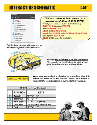
1. INTERACTIVE SCHEMATIC
The Bookmarks panel will allow you to
quickly navigate to points of interest.
Click on any text that is BLUE and underlined.
These are hyperlinks that can be used to navi-
gate the schematic and machine views.
When only one callout is showing on a machine view this
button will make all of the callouts visible. This button is
located in the top right corner of every machine view page.
VIEW ALL CALLOUTS
Cover Page
Information
Schematic
Machine Views
Component Table
Tap Table
Fluid Power Symbols
Electrical Symbols
Front Frame
Rear Frame
Tap Views
Features
Options
Bookmarks X
EC-C3
EC-C2 E-C60
EC-C1
E-C61
To set your screen resolution do the following:
RIGHT CLICK on the DESKTOP.
Select PROPERTIES.
CLICK the SETTINGS TAB.
MOVE THE SLIDER under SCREEN RESOLUTION
until it shows 1024 X 768.
CLICK OK to apply the resolution.
This document is best viewed at a
screen resolution of 1024 X 768.
FUNCTION
Zoom In
HOTKEYS (Keyboard Shortcuts)
Zoom Out
Fit to Page
Hand Tool
“CTRL” / “+”
KEYS
“CTRL” / “-”
“CTRL” / “0” (zero)
“SPACEBAR” (hold down)
Find “CTRL” / “F”
3. COMPONENT LOCATION
Description
Part
Number
Machine
Location
Schematic
Location
Accumulator GP
Cylinder GP - Boom
Cylinder GP - Bucket
Cylinder GP - Stick
Filter GP - Pilot (Hydraulic Oil)
Filter GP - Oil (Hydraulic Return)
Filter GP - Oil (Hydraulic, Case Drain)
Manifold GP - Control (Pilot Oil)
Motor GP - Swing
Motor GP - Travel (Left)
Pump GP - Piston (Main)
Swivel GP
Valve GP - Check (Oil Cooler Bypass)
Valve GP - Load Control (Boom)
Valve GP - Load Control (Stick)
Valve GP - Main Control
Valve GP - Pilot (Joystick, LH)
Valve GP - Pilot (Joystick, RH)
Valve GP - Pilot (Travel)
Valve GP - Pressure Reducing (Boom, Swing Priority)
Valve GP - Shuttle 1
Valve GP - Swing Cushion
Valve GP - Travel Counterbalance (Left)
Note A: Refer to Parts Manual for your specific machine.
Valve GP - Shuttle 2
Motor GP - Travel (Right)
Valve GP - Travel Counterbalance (Right)
164-6981
NOTE A
NOTE A
NOTE A
158-8987
188-4140
126-2075
215-5037
158-8986
209-5992
272-6955
234-4440
201-9329
255-5683
255-5680
259-7464
270-5951
270-5952
270-5947
232-4102
185-0462
259-7732
158-9085
137-3718
209-5992
137-3718
A-4
E-2
E-2
E-7
A-4
A-6
A-6
A-5
E-5
E-4
A-2
D-4
A-7
C-2
C-5
C-2
C-7
C-6
D-7
A-4
B-7
B-3
D-5
D-5
E-5
D-4
1
2
3
4
5
6
7
8
9
10
12
13
14
15
16
17
18
19
20
21
22
23
24
25
26
11
4. TAP LOCATION
Tap
Number Description
Schematic
Location
AA Pilot Filter Pressure Test Port
BB Idler Pump Pressure Test Port
CC Drive Pump Pressure Test Port
DD Power Shift Pressure Test Port
SOS Hydraulic Oil Sampling Port
A-4
B-3
A-3
A-2
A-3
5. FLUID POWER SYMBOLS
ONE POSITION TWO POSITION THREE POSITION
VENTED PRESSURIZED RETURN ABOVE FLUID LEVEL RETURN BELOW FLUID LEVEL
LINES CROSSING LINES JOINING
TWO-WAY THREE-WAY FOUR-WAY
SPRING CONTROL VALVES RESTRICTION LINE RESTRICTION
(FIXED)
2-SECTION PUMP
MAIN AUX.
SPRING
(ADJUSTABLE)
VARIABILITY LINE RESTRICTION
(VARIABLE)
LINE RESTRICTION
VARIABLE and PRESSURE
COMPENSATED
PRESSURE
COMPENSATION
PUMP: VARIABLE and
PRESSURE COMPENSATED
ENERGY TRIANGLES
HYDRAULIC PNEUMATIC
MEASUREMENT
PRESSURE TEMPERATURE FLOW
ROTATING SHAFTS
UNIDIRECTIONAL BIDIRECTIONAL
PUSH-PULL LEVER PEDAL
GENERAL MANUAL PUSH BUTTON SPRING
MANUAL CONTROL SYMBOLS
HYDRAULIC MOTORS
FIXED
DISPLACEMENT
VARIABLE DISPLACEMENT
NON-COMPENSATED
UNIDIRECTIONAL
BIDIRECTIONAL
HYDRAULIC PUMPS
FLUID STORAGE RESERVOIRS
CROSSING AND JOINING LINES
VALVE ENVELOPES VALVE PORTS
BASIC COMPONENT SYMBOLS
FLUID CONDITIONER
PUMP or MOTOR
FIXED
DISPLACEMENT
VARIABLE DISPLACEMENT
NON-COMPENSATED
UNIDIRECTIONAL
BIDIRECTIONAL
VALVES
PILOT CONTROL SYMBOLS
RELEASED PRESSURE
EXTERNAL RETURN INTERNAL RETURN
REMOTE SUPPLY PRESSURE
SIMPLIFIED COMPLETE INTERNAL
SUPPLY PRESSURE
ACCUMULATORS
SPRING LOADED GAS CHARGED
SOLENOID
or MANUAL
SOLENOID
and PILOT
SOLENOID and
PILOT or MANUAL
COMBINATION CONTROLS
SOLENOID SERVO THERMAL DETENT
HYDRAULIC AND PNEUMATIC CYLINDERS
DOUBLE ACTING
SINGLE ACTING
BASIC
SYMBOL
SPRING
LOADED
CHECK VALVES
TWO
POSITION
INFINITE
POSITIONING
FLOW IN ONE
DIRECTION
FLOW ALLOWED IN
EITHER DIRECTION
THREE
POSITION
CROSS
FLOW
PARALLEL
FLOW
INTERNAL PASSAGEWAYS
NORMAL POSITION
A B
P T
A B
P T
SHIFTED POSITION INFINITE POSITION
CONTROL VALVES
ATTACHMENT
MANUAL SHUTOFF
SHUTTLE PILOT
CONTROLLED
6. ELECTRICAL SYMBOLS
Hydraulic Symbols (Electrical)
325-AG135 PK-14
Circuit Identification
Number
Wire Color Wire Gauge
Harness identification code
This example indicates
wire 135 in harness "AG".
325-PK-14
Wire Gauge
Wire Color
Circuit Number
Identification
Wire Number Identification Codes
Current Standard
Previous Standard
Electrical Schematic Example Hydraulic Schematic Example
325-PK
Wire Color
Circuit Number
Identification
B A
Wire
Wire
(EXAMPLE VALVE)
Current Standard
Transducer
(Fluid)
Transducer
(Gas / Air)
G
Generator
Electrical Wire
Pressure Switch
M
Electric Motor
Pressure Switch
(Adjustable)
Temperature Switch
Pressure
Symbol
Temperature
Symbol
Level
Symbol
Flow
Symbol
Electrical Symbols (Electrical)
T
7. RENR7296-06
16
Page,
(Dimensions:
34
inches
x
24
inches)
A
B
C
D
E
1
2
3
4
5
6
7
A
B
C
D
E
1
2
3
4
5
6
7
HYDRAULIC CIRCUIT COLOR DESCRIPTIONS
PILOT PUMP OUTPUT
COMBINED LEFT AND RIGHT PUMP SIGNAL PRESSURE
IMPLEMENT AND LEFT TRAVEL PUMP OUTPUT
POWER SHIFT CONTROL CIRCUIT
SUPPLY LINE
SHUTTLE VALVE CONTROL CIRCUIT
STICK CONTROL AND STICK CYLINDER CIRCUIT
LEFT TRAVEL CONTROL AND LEFT TRAVEL MOTOR CIRCUIT
ATTACHMENT CONTROL CIRCUIT
SWING CONTROL AND SWING MOTOR CIRCUIT
DRAIN / RETURN LINE
SWING BRAKE CONTROL CIRCUIT
IMPLEMENT AND RIGHT TRAVEL PUMP
TRAVEL SPEED CONTROL CIRCUIT
BUCKET CONTROL AND BUCKET CYLINDER CIRCUIT
RIGHT TRAVEL CONTROL AND RIGHT TRAVEL MOTOR CIRCUIT
BOOM CONTROL AND BOON CYLINDER CIRCUIT
LINE PATTERNS
Drain / Return Lines
Component Group
Pilot / Load Sensing Pressure
Pressure Line
CALLOUTS
Taps (Pressure, Sampling, Sensor - by letter)
YY
(52) VALVE GP - CONTROL
138-1234
Callout Number
(Machine Location from
Component LocationsTable)
Component
Name
Part Number
aR3
RCV-C
RCV-B
RCV-A
aR4 bR3 bR4 bL3 bL2 bL4 aL2
bL4
bL3 bL2
bL1 bR1 bR3
bR4
bR1 aR1
aL1 bL1
aR3
aR4
aR1
aL1
aL2
AL3 BL3
AL2
BL2
BR1
BL1 AL1 AR1
AR3 BR3 AR4 BR4
BR3 AR3
AR4
BR4
BR1
AR1
AL1
AL2
AL3
BL3
BL2 BL1
TRAVEL(L) TRAVEL(R)
(20) VALVE GP
PILOT (TRAVEL)
270-5947
T1 T5
BACK
FWD
BACK FWD
T2 T4 T6 T3
JLP JLT
STICK SWING
OUT
JL1
IN
JL3
R L
JL2 JL4
BUCKET BOOM
OPEN CLOSE DOWN UP
JR1
JR2 JR3
JR4
A1 A2 A3 A4 A5 A6 A7 A8
B1 B2 B3 B4 B5 B6 B7 B8
(4) CYLINDER GP
STICK
P2 Pi1 DR1
DR2
DR3 DR4 DR5 DR6
P-IN PSA1
PAC
PSA2
T-OUT1
T-OUT2
Pi2
A
C
B
D E F
G
(14) VALVE GP
CHECK (OIL COOLER BYPASS)
201-9329
(6) FILTER GP
OIL (HYDRAULIC RETURN)
188-4140
(7) FILTER GP
OIL (HYDRAULIC, CASE DRAIN)
126-2075
(22) VALVE GP
SHUTTLE 1
185-0462
(8) MANIFOLD GP
CONTROL (PILOT OIL)
215-5037
JRT
(18) VALVE GP
PILOT (JOYSTICK, LH)
270-5951
(19) VALVE GP
PILOT (JOYSTICK, RH)
270-5952
(1) ACCUMULATOR GP
164-6981
NO.1
(TRAVEL)
NO.2
(SWING)
NO.3
(LOCK)
TRAVEL MOTOR (LEFT) TRAVEL MOTOR (RIGHT)
Pp3
BG
Pp3
BG
T1
T2
T1
T2
AG AG
A
B
A B
(3) CYLINDER GP
BUCKET
(2) CYLINDER GP
BOOM
M2
G2
G1 M1
A3
A1
S1
S3
A2
Pm
Pi
Pn1
Pn2
Ps2
Ps1
PsM1
Dr1
Dr2
DrM
PsM2
HL Di2
STICK(2)
BOOM(1)
ATCH BUCKET
TRAVEL(R)
TRAVEL(L)
SWING
STICK(1)
BOOM(2)
Pi2 Pi3 Di3 DST PL PR bR2 Di1 HR
AL4
SEE LOC A-7
SEE LOC A-7
aL4
SPi
SDr
SP3
Di4 Pi4 Pi1
BP3
BDr
BPi
R3
aR5
AR5
BR5
BT
BP1
AR2
BR2
aR2
(UP)
(OUT)
(IN)
(R)
(L)
(FWD)
(REV)
(FWD)
(REV)
(OPEN)
(CLOSE)
(UP)
(DOWN)
(OUT)
PG
DR
MU
BG AG
A
B
SWING MOTOR
P1 P2
T
A1 A2
B1 B2
aL3
(9) MOTOR GP
SWING
158-8986
(24) VALVE GP
SWING CUSHION
158-9085
(10) MOTOR GP
TRAVEL (LEFT)
209-5992
(25) VALVE GP
TRAVEL COUNTERBALANCE (LEFT)
137-3718
(11) MOTOR GP
TRAVEL (RIGHT)
209-5992
(26) VALVE GP
TRAVEL COUNTERBALANCE (RIGHT)
137-3718
(13) SWIVEL GP
234-4440
(15) VALVE GP
LOAD CONTROL (BOOM)
255-5683
(16) VALVE GP
LOAD CONTROL (STICK)
255-5680
(17) VALVE GP
MAIN CONTROL
259-7464
(12) PUMP GP
MAIN
272-6955
RCV: RETURN CHECK VALVE
(5) FILTER GP
PILOT (HYDRAULIC OIL)
158-8987
bR5
IN
OUT
T
DR A1
B1
PG
U
FR
RR
(21) VALVE GP
PRESSURE REDUCING
(BOOM, SWING PRIORITY)
232-4102
(23) VALVE GP
SHUTTLE 2
259-7732
PC
P1
JRP
T
BP2
P
U
M
P
R
I
G
H
T
P
U
M
P
L
E
F
T
PILOT
I
D
TRAVEL BRAKE
TRAVEL BRAKE
PRESSURE SWITCH PRESSURE SWITCH
PRESSURE SWITCH
SLOW
RETURN BYPASS
OIL COOLER
TRAVEL
SPEED
SWING
PRIORITY
A
C
T
I
V
A
T
I
O
N
H
Y
D
R
A
U
L
I
C
PRESSURE
SENSOR
PROPORTIONAL
REDUCING VALVE
MAIN
RELIEF
PRESSURE SENSOR
RCV-C
RCV-A
RCV-B
SEE LOC A-7
SEE LOC C-2
SEE LOC E-6
SEE LOC C-6
HL
HR
PL
PL
PR
PR
HL
HR
AA SOS
CC
BB
DD
Components are shown installed on a fully operable machine with the key and engine off,
and with parking brake set.
Refer to the appropriate Service Manual for Troubleshooting, Specifications and Systems Operations.
SCHEMATIC PART NUMBER: 259-7469, CHANGE: 01, VERSION: HE
MEDIA NUMBER: RENR7296-06
THIS SCHEMATIC IS FOR THE 320D AND 320D L EXCAVATOR HYDRAULIC SYSTEM