


![5 LITERATURE SEARCH
In this section we will discuss about;
1. The latest capabilities and features in leading commercial CAD/CAM systems in
production of tooling and dies.
2. The latest developments and systems in Computer Aided Process Planning to overcome
the problems of traditional process planning.
3. The latest trends and systems in rapid prototyping technologies in fabrication of dies for
injection moulding.
Both tools and dies require good design for strength, durability. In order to obtain the specific shape or
the stamp most of the designing is done using CAD/CAM due to its higher accuracy and precision and
adaptability.
5.1 The latest capabilities and features in leading commercial CAD/CAM systems
in production of tooling and dies.
5.1.1 STEP-NC
In the machining domain, over-loading of spindle torque, excessive cutting force, chatter, tool
wear and other constraints may lead to major problems such as tool breakage and product quality
deterioration. These problems increase the cost of a product so that it becomes less competitive in the
market. To reduce production costs and guarantee sustained product quality, it is necessary to keep
tolerances checked as well as actively monitor machine tool conditions. Tool wear and surface roughness
are commonly used as sources of information about machine tool conditions. The STEP-NC data model
introduces feed-rate optimisation based on a cutting force prediction model implemented at the process
planning stage, and real-time process control at shop-floor. [1]
This data model was introduced to reduce the 3 common errors that can happen in CNC machining which
Chapter: LITERATURE SEARCH
are static errors, dimensional errors and surface roughness errors[1] it provides an object oriented data
model for CNCs with a detailed and structured data interface that incorporates feature-based
programming where a range of information is represented such as the features to be
machined, tool types used, the operations to perform, and the sequence of operations to follow.[2]
9](https://image.slidesharecdn.com/carremote-13333167928612-phpapp01-120401170506-phpapp01/85/Car-Remote-CAD-CAM-10-320.jpg)
![5.1.2 IKMOULD
This is a practical prototype knowledge-based system, for mould design in the injection moulding
process. It attempts to tackle the problem in a practical and integrative way, unlike the stand-alone and
mathematical programs which have been developed in the past to solve only a part of the problem. A total
quantitative and structured approach is not feasible in dealing with the complex and multi related design
problems generally involved in mould design. In this system, the
1. computational module
2. the knowledge-based module
3. the graphic module
for generating mould features are integrated within an interactive CAD based framework. The knowledge
base of the system can be accessed by mould designers through interactive programs so that their own
intelligence and experience can also be incorporated with the total mould design. The approach adopted
both speeds up the design process and facilitates design standardisation which in turn increases the speed
of mould manufacture.[3]
5.1.3 COLLABORATIVE MOULD DESIGN
In the quest to reduce time consumption when designing moulds the concurrent/ collaborative
mould design system has stood out. The major contribution of the collaborative mould design navigation
system is the integration of the five major modules, conceptual design, mould split, mould base, drawing,
and design change, into the first-layer modules of conceptual design and mould design. [4]The moulds are
represented and stored as a complete geometric and topological solid in term of faces, edges, and vertices
in three dimension, so it is suitable for display, engineering analyses and simulation.[5]
5.1.4 VIRTUAL ENVIRONMENT FOR DESIGN AND MANUFACTURING (VEDAM)
VEDAM is a fascinating modern and upcoming technology in the design and manufacturing
industry. This is a system which is designed and partially implemented to support virtual design of
manufacturing and l assembly which would extend the capabilities and the parametric of the CAD/CAM
systems. Also VEDAM system and its existing CAD/CAM system would allow quick and easy
modification of design in order to obtain the desired mould design which enhances the capability of
Chapter: LITERATURE SEARCH
elimination of time through the stage of the product design. ―This is a technology would save time & cost
in the process of creating a design for moulding or welding‖. [16]
10](https://image.slidesharecdn.com/carremote-13333167928612-phpapp01-120401170506-phpapp01/85/Car-Remote-CAD-CAM-11-320.jpg)
![5.2 The latest developments and systems in Computer Aided Process planning to
overcome the problems of traditional process planning.
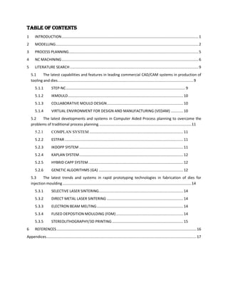
Process planning is the systematic determination of the detailed methods by which parts can be
manufactured from raw material to finished product. In recent years, computer aided process planning
(CAPP) has been recognised as a key element in computer integrated manufacturing (CIM). [15]
A good process plan of a part is built up based on two elements:
optimized sequence of the operations of the part
optimized selection of the machine, cutting tool and tool access direction (TAD) for each
operation [6]
5.2.1 COMPLAN SYSTEM
COMPLAN is a generative/variant of CAPP systems. This process-planning system, has been
designed for small batch manufacturing of mechanical parts and is mainly developed in the C++
language. The modules of the COMPLAN system can be arranged in two main functional groups: process
planning and workshop scheduling. [15]
The COMPLAN system realises economic improvements such as: [15]
A shortening of the lead time from design to manufacturing and reducing the effort spent to enter
CAD data into a CAPP system, and by rationalising the process-planning effort needed.
Achieving a leaner and more flexible production organisation.
5.2.2 ESTPAR
ESTimator of PARameters (ESTPAR) is a generative approach to a CAPP system. The
knowledge-based expert system along with the GP code is called ESTPAR. The ESTPAR system can be
used by manufacturing personnel to determine the optimal machining parameters and the corresponding
machining costs when using different combinations of machines, tools, and fixtures (MTF). [15] Chapter: LITERATURE SEARCH
5.2.3 IKOOPP SYSTEM
Intelligent knowledge-based objective-oriented process planning (IKOOPP) is a generative CAPP
system. Because of the problems associated with manual process planning, and the inconsistencies of the
plans, the IKOOPP system has been developed to automate and standardise the process planning function
for the manufacture of progressive dies. [15]
11](https://image.slidesharecdn.com/carremote-13333167928612-phpapp01-120401170506-phpapp01/85/Car-Remote-CAD-CAM-12-320.jpg)
![5.2.4 KAPLAN SYSTEM
Knowledge-based approach to process planing (KAPLAN) is a generative CAPP system [16].
KAPLAN provides fully automatic generation of productions plans of rotational parts. The program
structure is based on knowledge base techniques and the knowledge required for the plan generation is
represented by IF-THEN rules, easily adapted to every workshop environment by means of a user
interface. [15]
5.2.5 HYBRID CAPP SYSTEM
To trade off the advantages and disadvantages of a purely generative CAPP system and a variant
CAPP system, some researchers have proposed a semi-generative approach to CAPP, which is basically a
combination of the variant and generative methods. The aim of such a system is to reduce user interaction
by incorporating standard operation sequences, heuristic rules and mathematical formula to the system.
COMPLAN is such a system, and can be called a hybrid CAPP system. A hybrid CAPP system allows for
a low degree of automation in the early stages and increases the degree of automation for which a
knowledge base can easily be systematized. This characteristic avoids the long implementation time of
the CAPP system resulting from the need to create a knowledge base.[7]
5.2.6 GENETIC ALGORITHMS (GA)
In the past two decades, GA has been widely applied for solving complex manufacturing
problems, e.g. job shop scheduling and process planning. Genetic algorithms (GA) are chosen for solving
optimization problems. The process planning is divided into preliminary planning and secondary/detailed
planning. In the preliminary stage, feasible sequences of operations is carried out considering compulsive
constraints of operations using the proposed GA and during the secondary and detailed level of planning,
the optimized sequence of the operations of the part, and the optimized selection of the machine, cutting
tool, and tool access directions (TAD) for each operation is acquired using a genetic algorithm
considering additive constraints as well. It means during the secondary of planning, relevant
manufacturing information, such as, machine tools, cutting tools, and TADs for the operations of the part
is determined.[6]
The GA mimics the process of natural evolution by combining the survival of the fittest among solution
Chapter: LITERATURE SEARCH
structures with a structured, yet randomized, information exchange and creates offspring. In GA, a
candidate solution is represented by a sequence of numbers known as chromosome or string. In the
present work, each element (gene) in a string (chromosome) represents an operation. The order of the
elements in the string represents the sequence to be followed. A judiciously selected set of chromosomes
is called a population and the population at a given time is a generation. The population size, which
remains fixed from generation to generation, has a significant impact on the performance of the GA. This
size is to be specified by the user depending upon the number of elements in the string and the problem
12](https://image.slidesharecdn.com/carremote-13333167928612-phpapp01-120401170506-phpapp01/85/Car-Remote-CAD-CAM-13-320.jpg)
![complexity. A randomly generated set of sequences (strings) makes the initial population. Optimization of
the initial sequences is done by GA, using an appropriately defined fitness function. [6]
Chapter: LITERATURE SEARCH
13](https://image.slidesharecdn.com/carremote-13333167928612-phpapp01-120401170506-phpapp01/85/Car-Remote-CAD-CAM-14-320.jpg)
![5.3 The latest trends and systems in rapid prototyping technologies in fabrication
of dies for injection moulding
5.3.1 SELECTIVE LASER SINTERING
Selective laser sintering (SLS) is a rapid prototyping process that allows to generate complex 3D
parts by solidifying successive layers of powder material on top of each other. Solidification is obtained
by fusing or sintering selected areas of the successive powder layers using thermal energy supplied
through a laser beam . A beam deflection system (galvano mirrors or XY table makes the beam scan each
layer according to the corresponding cross section of the part as calculated from a CAD model. A powder
deposition system is used for depositing the successive thin layers of powders (typically 0.1-0.3mm
thickness) in a building container before that layer is laser sintered.[11]
5.3.2 DIRECT METAL LASER SINTERING
Direct metal laser sintering (DMLS) fabricates metal prototypes and tools directly from computer
aided design (CAD) data. The process is popular in rapid tooling (RT) ,since a suitable metal powder can
be used to produce the metal parts and tools. The powder system may be pre-alloyed powder or multi-
phase powder. The properties of the RT parts, however, depend on its composition and solidification
conditions. Accuracy, wear resistance and mechanical properties are critical on choosing the rapid tooling
mould as the production-grade tooling. Perhaps this fabrication has similar characteristics as target metal
characters’ but not a process of Laser Cladding or Laser process involves.
5.3.3 ELECTRON BEAM MELTING
Surface melting and alloying of steel using an electron beam has been carried out to improve its
surface microstructure and properties. The solution of primary carbides, together with rapid solidification
and subsequent cooling, enhance the solubility of alloying elements in the y Fe phase and thus influence
the behaviour of the steel on subsequent tempering. The surface melted zone consists of dendrites without
primary carbides. [13]
5.3.4 FUSED DEPOSITION MOULDING (FDM)
Fused deposition modelling (FDM) is one of the most widely used rapid prototyping systems in
Chapter: LITERATURE SEARCH
the world.[12] The FDM systems, developed by Stratasys Inc, currently fabricate parts in elastomers,
ABS and investment casting wax using the layer by layer deposition of extruded material through a
nozzle using feedstock filaments from a spool. Most of the parts fabricated in these materials can be used
for design verification, form and fit checking and patterns for casting processes and medical application.
[12]
14](https://image.slidesharecdn.com/carremote-13333167928612-phpapp01-120401170506-phpapp01/85/Car-Remote-CAD-CAM-15-320.jpg)
![5.3.5 STEREOLITHOGRAPHY/3D PRINTING
Starting from a 3D image, a part is built slice by slice from bottom to top, in a vessel of liquid
polymer that hardens when struck by a laser beam. Starting from a STL file, the required supports for
overhangs and cavities are automatically generated in the model under construction. The support and
model files are then "cut" into thin horizontal slices and programmed into the stereo-lithography 3-d
printing machine.
This machine then uses a computer controlled laser to draw the bottom cross section onto the surface of a
liquid polymer that hardens where struck by the laser. The part is then lowered to a depth corresponding
to the section's thickness and the next cross section is then drawn directly on top of the previous one. This
is repeated until the part is finished. The supports are removed manually after the product is taken from
the stereo-lithography machine. [8]
The reasons to choose stereo-lithography can be the following [9]
1. Fast: Parts in as little as 2 days
2. High level of accuracy and high surface quality
3. Representative parts for visual testing
4. Functional parts
5. Small and large parts - from intricate switch component to car dashboard built in a single piece
6. Wide range of finishing options
7. Wide range of materials
Stereo-lithography (SLA) can be considered a rapid prototyping(RP) technology[10]
Chapter: LITERATURE SEARCH
15](https://image.slidesharecdn.com/carremote-13333167928612-phpapp01-120401170506-phpapp01/85/Car-Remote-CAD-CAM-16-320.jpg)


The document provides a table of contents for sections on modelling, process planning, NC machining, and literature search on CAD/CAM technologies for tooling and dies. It then summarizes the modelling of a remote control car part in Pro/Engineer including sketches, extrusion, shell creation, and hole features. The process planning section outlines creating a process plan table for NC milling operations on the cavity and core including operation descriptions, tools, machining parameters and clearances. Finally, the NC machining section describes creating the mould components from the model and performing draft checks on the core and cavity parts.


