Five Zones Split Tube Furnace is a CE certified split 80mm OD (3" I.D) Five-zone tube furnace which can achieve faster heating up to 1200oC and create smooth thermal gradient or one uniform constant temperature zone by adjust four zone temperature.
The easiest and reliable way of building houses, villas, camps, towns, ... Light steel gauge buildings obtain low costed and quickest way of construction for permanent and temporary solutions. Either for an economical apartment or a luxury villa ... Or a hangar to any heavy steel building ...
Serving various clients including corporate offices, convention centres, Educational Institutes, Hotels etc. for last decade by the name & style of “Indrayani” Seating Systems.
A research study of Donald u. Bulawin, Cristian Ralph E. Ibahay, and Mabeth L. Arellano. It is all about utilizing the waste bottle caps for concrete mixture. This study aims that by utilizing the waste bottle caps as a partial replacement for coarse aggregates helps in increasing the strength of concrete and in the environmental issues of wastes disposal.
EDUARDO H. PARE SPECS & SW_BUILDING & UNDERGROUND CABLES CIVIL WORKSEduardo H. Pare
SPECIFICATIONS & SCOPE OF WORKS
FOR BUILDING & UNDERGROUND CABLES CIVIL WORKS
AUTHOR: EDUARDO H. PARE, BSCE, HAU, EPCC, PMC
CIVIL/STRUCTURAL ENGINEER
DESIGN & CONSTRUCTION
EDUARDO H. PARE CIVIL, STRUCTURAL AND ARCHITECTURAL SPECIFICATIONSEduardo H. Pare
CIVIL, STRUCTURAL AND ARCHITECTURAL WORKS
DESIGN & CONSTRUCTION SPECIFICATIONS
AUTHOR: EDUARDO H. PARE, BSCE, HAU, EPCC, PMC
CIVIL/STRUCTURAL ENGINEER
DESIGN & CONSTRUCTION
General Specification for Thermofoil Heater, All-Polyimide, Space ApplicationsBelilove Company-Engineers
Purpose. This specification establishes the requirements for thermofoil heaters of an all- polyimide (adhesive-less) construction for high reliability space applications. It defines the process, test verification, and inspections required by product used in space flight applications.
1. 03_Ground Floor
0
05_First Floor
2890
07_WallPlate
5610
02_NGL
-255
A B C D E F G H I J K L M
08_Roof pitch
7200
04_Lintel
2125
06_Lintel
5015
10°
FINISH ROOF SHEETING
0.6mm Chromadek finish
corrugated sheeting on 38x38mm
SA Pine 6 Grade Pulins Secured
to 140x76mm SA Pine Trusses
space 1000mm ctc (Advise engineers specs)
Plaster & Paint wall Finish
Plaster & Paint wall Finish
Plaster & Paint wall
Finish
Plaster & Paint wall Finish
600x600 Porcelain Tile 2mm
joints deco finish
FHFH
stainless steel sign
TBC
Refuse Area non- porous
finish ie: Plaster and Paint
Wall mounted light
fixtureStainless steel balustrade and
hand rail @900mm
FH FH
03_Ground Floor
0
05_First Floor
2890
07_WallPlate
5610
02_NGL
-255
14 23
08_Roof pitch
7200
04_Lintel
2125
06_Lintel
5015
Stainless steel balustrade
and hand rail @900mm
Plaster & Paint wall
Finish
Plaster & Paint wall
Finish
FINISH ROOF SHEETING
0.6mm Chromadek finish
corrugated sheeting on 38x38mm
SA Pine 6 Grade Pulins Secured
to 140x76mm SA Pine Trusses
space 1000mm ctc (Advise engineers specs)
300x300mm Concrete Slanted Column
Erected According to Engineers Specs.
Clad Finish 150x150 Rough Cut
Granite Tiles
900
03_Ground Floor
0
05_First Floor
2890
07_WallPlate
5610
02_NGL
-255
1 42 3
08_Roof pitch
7200
04_Lintel
2125
06_Lintel
5015
Stainless steel balustrade
and hand rail @900mm
Plaster & Paint wall
Finish
Plaster & Paint wall
Finish
FINISH ROOF SHEETING
0.6mm Chromadek finish
corrugated sheeting on 38x38mm
SA Pine 6 Grade Pulins Secured
to 140x76mm SA Pine Trusses
space 1000mm ctc (Advise engineers specs) 10°
03_Ground Floor
0
05_First Floor
2890
07_WallPlate
5610
ABCDEFGHIJKLM
Tap with Gully
08_Roof pitch
7200
04_Lintel
2125
06_Lintel
5015
whb
wc
urinal
sink
whb
wc
urinal
sink
Tap with Gully
whb
wc
urinal
sink
whb
wc
urinal
sink
All Windows recessed
1500mm from boundary
line
FINISH ROOF SHEETING
0.6mm Chromadek finish
corrugated sheeting on 38x38mm
SA Pine 6 Grade Pulins Secured
to 140x76mm SA Pine Trusses
space 1000mm ctc (Advise engineers specs)
Plaster & Paint wall
Finish
Plaster & Paint wall
Finish
01_Foundation
-510
03_Ground Floor
0
05_First Floor
2890
07_WallPlate
5610
02_NGL
-255
D E F G H I
08_Roof pitch
7200
04_Lintel
2125
06_Lintel
5015
320
2140
Office Space Kitchenette Female WC Foyer/stair well
Office Space Kitchenette Female WC
Foyer/stair well
Office SpaceKitchenetteMale WC
Office SpaceKitchenetteMale WC
dpc dpc dpc dpc dpc
Structure
continues
Structurecontinues
1000
600x1200 Suspended ceiling
50mm Isover Insulation 600x1200 Suspended ceiling
50mm Isover Insulation
600x1200 Suspended ceiling
50mm Isover Insulation
600x1200Trof light fitting
600x1200Trof light fitting600x1200Trof light fitting600x1200Trof light fitting
600x1200Trof light fitting 600x1200Trof light fitting 600x1200Trof light fitting 600x1200Trof light fitting 600x1200Trof light fitting
600x1200Trof light fitting 600x1200Trof light fitting
6003401702400521832552400521858
01_Foundation
-510
03_Ground Floor
0
05_First Floor
2890
07_WallPlate
5610
02_NGL
-255
14 23
08_Roof pitch
7200
04_Lintel
2125
06_Lintel
5015
03
Pg_01
10°
Grade 8 SA Pine Trusses
space 1000mm ctc (Advise
engineers specs)
Pre cast concrete
floor 250mm thick
1262
CeilingHeight2400CeilingHieght2400
Strip Foundation According
to Engineers Specs
01_Foundation
-510
01_Foundation
-510
03_Ground Floor
0
05_First Floor
2890
07_WallPlate
5610
02_NGL
-255
1 42 3 Detail 1
05
Pg_02
Detail 2
08_Roof pitch
7200
04_Lintel
2125
06_Lintel
5015
04
Pg_02
07
Pg_02
06
Pg_02
Detail 4
Detail 3
10°
FH
01_Foundation
-510
03_Ground Floor
0
05_First Floor
2890
07_WallPlate
5610
02_NGL
-255
14 23
08_Roof pitch
7200
04_Lintel
2125
06_Lintel
5015
10°
Grade 8 SA Pine Trusses
space 1000mm ctc (Advise
engineers specs)
1862
Foyer
Foyer Entrance DBL Door
braced within curtain
wall
Canter lever balcony
CeilingHeight2400
CeilingHeight2140
900
Stainless steel balustrade
and hand rail @900mm
1000
Balcony DBL Door
braced within curtain
wall
6001687171321255951590
dpc
dpc
170
255241
ID² Interior Design Solutions
1.COPYRIGHT
1.1 Copyright exists in terms of the Copyright Act No 96 of 1978
1.2 copyright of these drawings and the design in which they were depicted
designer elements within Any Unauthorized copying of the drawing or use of
design constitutes an infringement of the copyrights and is a criminal offense
1.3 In addition to criminal prosecution, the owner is entitled to sue of damages
and claim delivery of such infringement documentation and copies thereof
1.4 The copyright infringement includes the sale or distribution thereof
2.LAWS AND REGULATIONS
2.1 All works and building materials are to comply with National Building
Regulations(SAB70400) and building standards Act No:103 of 1977, as amended
2.2 All work is to be carried out in accordance to strict by laws and regulations of
the regional local authorities
2.3 Light and ventilation are to comply to part O of the national building regulations
3.DRAWINGS
3.1 Shop drawings must be approved by designer PRIOR to any manufacture of
fittings or furniture items
3.2 Concise detail drawing are preferred over arrangement sketches and must its
own legality
3.3 One set of working documentation is to remain on site permanently till site is
completed.
3.4 All amended working documentation must replace previous working
documentation and must clear state AMENDED, a set of amend working drawings
are to be handed to contractor within a 12 hour period of amendment
4.DIMENSIONS
4.1 Contractors and subcontractor are to check and verify dimensions and detail
levels before commencing with work
4.2 Figured dimensions are to be use if working drawing scale is incorrect
5.VARIATION & AMENDMENTS
5.1 The designer is to be notified of all variations by the project manager
5.2 All relevant detail levels and dimensions of any working done must be checked
onsite by relevant contractors before the commencements of work, Any
discrepancies are to be reported to the project manager and designer
immediately
6.CONTRACTORS AND SUBCONTRACTORS
6.1 Contractors must ensure structural integrity of all components at all times and
ensure that the main structure is capable of supporting any additional components
and additional loads applied thereto
6.2 All electrical and water systems to be worked on by an authorized artisan with
corresponding documentation
7.SHOPFITTING ITEMS
7.1 Shop fitted items are to measured onsite and shop drawings are to be
approved by the designer and client PRIOR to commencement of work
8.PARITIONS
8.1 All portions walls connecting directly to the outside wall should ad heard to
NBR and fire regulations a minimun fire rating of 30min
8.2 All mechanical joints should ad hear to NBR and relevant suppliers
ID² Interior Design Solutions
SANS 10400-XA:2011
PART4
4 Requirements
4.1 Hot water supply
4.1.1(a) the volume of the annual average hot water heating
requirements
4.1.1(b) if solar water heating systems are used, these shall comply with
SANS 1307, SANS 10106,
SANS 10254 and SANS 10252-1.
4.1.3 All hot water service pipes shall be clad with insulation with a
minimum R-value in table 1&6
4.2 Energy usage and building envelope
4.2.1(a) in any building of occupancy classified in terms of Regulation A20
must have competent person certifies that such building
(excluding garage and storage areas) has atheoretical annual
energy consumption and demand, based on the design
assumptions contained in less than or equal to the values
specified in tables 2 & 3;
OR
4.2.1b) in any building of occupancy classified in terms of Regulation A20
as tables A2, A3, A4, C1, C2, E1,E2, E3, E4, F1, F2, F3, G1, H1,
H2, H3, H4, and H5, the orientation and shading are in
accordance with the requirements of SANS 204,
4.3 Design assumptions
where artificial ventilation systems are provided
1) the design occupancy times are in accordance with table 4;
2) the space temperature lies within the range of 19 °C to 2°5C
for 98 % of the plant operation time;
3) ventilation is provided in accordance with the requirements of
SANS 10400-O;
4) the internal heat gains in the building are from
i) the design population calculated in accordance with table 5 at
an average rate of 75 W sensible heat gain per person;
ii) hot meals in a dining room, restaurant or café, at at rate of 30
W heat gain per person- table 5;
iii) appliances and equipment- table 6;
iv) artificial lighting calculated with table 4;
4.3(b) hot water supplies
4.3(c) the maximum energy demand and maximum energy usage are
calculated for the total building and not for individual tenancies.
table 4.1
4.4 Building envelope requirements
4.4.1 Orientation
4.4.1.1 The building should be compact in plan, with the rooms that are
used most and the major areas of glazing placed on the
northern side of the building to allow solar heat to penetrate the glazing
during the winter months.
4.4.1.2 The roof overhang to the northern wall shall be sufficient to shade
the windows from midday summer sunshine in accordance with
SANS 204. Windows facing east and west should be limited in
number and confined to the minimum required for daylight and
ventilation.
4.4.2 Floors
Where an underfloor heating system (e.g. in-screed,
underlaminate heating, undercarpet heating, undertile heating, cutin
underfloor heating, and water-based underfloor heating) is installed,
the heating system shall be insulated underneath the slab with
insulation that has a minimum R-value of not less then 1,0.
4.4.3 External walls
4.4.3.1 Non-masonry walls shall achieve a minimum total R-value of
a) climatic zones 1 and 6: 2,2
b) climatic zones 2, 3, 4 and 5: 1,9.
4.4.3.2 The following types of masonry walling comply with the R-value
requirements:
a) double-skin masonry with no cavity, plastered internally, or
rendered externally; or
b) single-leaf masonry walls with a nominal wall thickness greater
than or equal to 140 mm (excluding plastering and rendering), plastered
internally and rendered externally.The requirements refer to the
external walls of the habitable portions of the building fabric only.
4.4.3.3 For masonry walling types not covered in 4.4.3.2, such wallssh all
achieve a minimum total R-value of 0,35. The total R-value shall
be determined by means of a test conducted in accordance
with ASTM C 1363, ASTM C 518 or ASTM C 177.Surface film resistance shall
be in accordance with SANS 6946.4.4.3.4 Other walling
requirements shall be in accordance with SANS 10400-K.
4.4.4 Fenestration
4.4.4.1 Buildings with up to 15 % fenestration area to nett floor arepae r
storey comply with the minimum energy performance equirements.
4.4.4.2 Buildings with a fenestration area to nett floor area per stortehya t
exceeds 15 % shall comply with the equirements for fenestration in
accordance with SANS 204.
4.4.4.3 All fenestration air infiltration shall be in accordance with SANS 613.
4.4.5 Roof assemblies
4.4.5.1 A roof assembly R-value specified in table 7
4.4.5.2 A roof assembly that has metal sheet roofing fixed to metal purlins,
metal rafters or metal battens shall have a thermal break consisting
of a material with an R-value of not less than 0,2 installed between the
metal sheet roofing and its supporting member
4.4.5.3 Metal sheeting types of roofing assembly -table
PO BOX 20958
Noordbrug
Potchefstroom
2522
Cel:082 479 2017
Client :
Project Name :
Project Site Address:
Inception Date : Current Date :
Project Status:
Page Title:
Design:
Council Approval :
Scale:
Drawn:
Date :
Client Approval : Date :
ClimateZone:2
Page #:
Project #:
As
indicated
2015/06/0112:30:03PM
Author
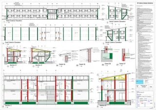
Planning
Elevations & Sections
05/28/15
Pg_02
Capalie Botha
Office Block Maree Str
Erf: 2640/10 No 3 Maree Str, Potchefstroom,
Tlokwe
Author
1 : 100
West Exterior Elevation
1
1 : 100
North Exterior Elevation
2
1 : 100
South Exterior Elevation
31 : 100
East Exterior Elevation
4
1 : 50
Section C
D
1 : 100
Section A
A
1 : 50
Section B
B
1 : 100
Section D
C 1 : 20
Detail 05
05 1 : 20
Detail 06
06 1 : 20
Detail 07
07
1 : 20
Detail 04
04
0.6 chromadek roof sheeting
76x38mm SA pine grade 8 purlins
generic seamless gutter profile mounted to
fascia board
SA pine grade 8 truss spaced @1000mm
nail plate
suspension tee for suspended ceiling
50mm Isover insulation
5mm galvanized anchor wire
290mm cavity wall with wall ties @ every
3 course
0.6 chromadek roof sheeting
76x38mm SA pine grade 8 purlins
SA pine grade 8 truss spaced @1000mm
290mm cavity wall with wall ties @ every
3 course
2mm thick truss wall hanger bolted to wall
with expansion bolts
Strip Foundation According
to Engineers Specs
150mm layer hardcore fill
170mm re-inforced concrete floor
255mm pre-cast concrete floor
according to engineers
specifications
1200x600 tile suspended ceiling
set @ 2400mm above FFL
coolinterior
Rev
No.
Description of
changes Date