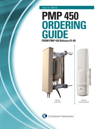
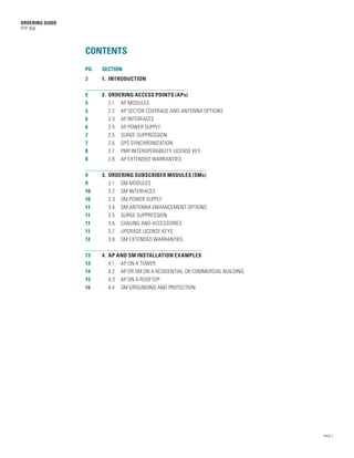
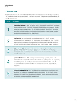
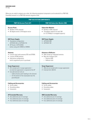
SlideShare a Scribd company logo
Issue 1.0 โ€“ 08.22.12


PMP 450
ORDERING
GUIDE
FROM PMP 450 Release 01-00


                PMP 450                PMP 450
               Access Point        Subscriber Module


                              TM
ORDERING GUIDE
PTP 450


                 CONTENTS
                 PG 	   SECTION
                 3	     1.	 INTRODUCTION

                 5	  2.	 ORDERING ACCESS POINTS (APs)
                 5		 2.1		 AP MODULES
                 5		 2.2	 AP SECTOR COVERAGE AND ANTENNA OPTIONS
                 6 		 2.3	 AP INTERFACES
                 6 		 2.4	 AP POWER SUPPLY
                 7 		 2.5	 SURGE SUPPRESSION
                 7 		 2.6	 GPS SYNCHRONIZATION
                 8 		 2.7	 PMP INTEROPERABILITY LICENSE KEY
                 8 		 2.8	 AP EXTENDED WARRANTIES

                 9	   3.	 ORDERING SUBSCRIBER MODULES (SMs)
                 9		 3.1		 SM MODULES
                 10 		 3.2	 SM INTERFACES
                 10 		 3.3	 SM POWER SUPPLY
                 11 		 3.4	 SM ANTENNA ENHANCEMENT OPTIONS
                 11		 3.5	 SURGE SUPPRESSION
                 11 		 3.6	 CABLING AND ACCESSORIES
                 11 		 3.7	 UPGRADE LICENSE KEYS
                 12 		 3.8	 SM EXTENDED WARRANTIES

                 13 	 4.	 AP AND SM INSTALLATION EXAMPLES
                 13 		 4.1		 AP ON A TOWER
                 14 		 4.2	 AP OR SM ON A RESIDENTIAL OR COMMERCIAL BUILDING
                 15 		 4.3	 AP ON A ROOFTOP
                 16 		 4.4	 SM GROUNDING AND PROTECTION	


                                                                               PAGE 2
ORDERING GUIDE
PTP 450


1. INTRODUCTION

This Ordering Guide covers the Cambium PMP 450 Platform. It is intended to provide a structured guide to ordering
a link with any accessories and ancillary items for a successful installation. The key steps involved in planning and
ordering your system are:

   STEPS         ACTIVITIES


                   Regulatory Planning: To begin, you need to contact the applicable radio regulator in your area
                   to identify any restrictions or limitation imposed on radio equipment operating in your planned

     1             RF band and to determine whether or not you need to register your PMP network. As the user
                   of the radio equipment, it is your responsibility to ensure that your system complies with any
                   regulatory guidelines imposed by the local regulator.


                   Site Planning: We recommend that you complete a site survey to identify the many


     2             considerations critical for successful site selection such as the availability of tower or rooftop
                   space, the location of the grounding system, best positioning of the APs and SMs, aesthetics
                   and other permission-based issues, and maximum cable lengths required for your deployment.


                   Link and Sector Planning: You need to determine link-planning factors such as path

     3             obstructions, risk of interference, path and link loss, maximum power levels permitted, and
                   coverage requirements.


                   Spectrum Analysis: One of the most important elements in your planning process is the
                   analysis of spectrum usage and signal strength needed to occupy the spectrum you are planning

     4             to use. In this process, you need to plan your sector coverage to determine how many APs
                   will be needed and what sector size will be required to provide adequate coverage for the
                   deployment.


                   Preparing a PMP 450 Order: Once you have identified all the regulatory requirements and


     5             planned the site, link, sector coverage and spectrum requirements, you are ready to compile
                   your order. This Ordering Guide provides the part numbers, product descriptions, instructions,
                   and resources to help you complete a PMP 450 order.


                                                                                                                        PAGE 3
ORDERING GUIDE
PTP 450


When you are ready to prepare your order, the following equipment components can be selected for a PMP 450
Greenfield network or a a PMP 450 network migration order.

                                          PMP 450 SYSTEM COMPONENTS

              PMP 450 Access Point (AP)                            PMP 450 Subscriber Module (SM)


   Access Point:                                             Subscriber Module:
   โ€ข	
     Number of APs required                                  โ€ข	 Number of SMs required
   โ€ข	
     60-degree sector or 90-degree sector                    โ€ข	Throughput capacity for each SM
                                                                (4, 10, 20 Mbps or uncapped capacity)


   30V Power Supply:                                         30V Power Supply:
   โ€ข	
     Standalone configuration:                               โ€ข	 ACPSSW-09B
     ACPSSW-20A or ACPSSW-21A                                โ€ข	 ACPSSW-13B
   โ€ข	 Cluster: ACPS120WA
     AP
     (when using with CMM3 or CMM4)


   Antenna:                                                  Antenna or Reflector:
   โ€ข	6-sector dual mode antenna (FSK and OFDM)              โ€ข	 SMs include an integrated antenna
   โ€ข	 4-sector OFDM antenna                                  โ€ข	 May also configure with:
   โ€ข	Alternative configuration                              	 โ€“ Passive LENS
      (verify regulations prior to purchase)                 	 โ€“ Reflector dish


   Surge Suppressor:                                         Surge Suppressor:
   โ€ข	 include built-in surge suppression โ€“
      APs                                                    โ€ข	 SMs do not include built-in surge suppression
      no external suppression is required at the AP          โ€ข	 External Unit: 600 SS
   โ€ข	 Can add external units at:
   	 โ€“  able entrance point leading to the network
         C
   	 โ€“  n the bottom of the tower/pole near the
         O
         grounding bar


   Cabling and Accessories:                                  Cabling and Accessories:
   โ€ข	 Cat 5e cables                                          โ€ข	 Cat 5e cables
   โ€ข	 Grounding cables                                       โ€ข	 Grounding cables
   โ€ข	 Connectors                                             โ€ข	 Connectors


   AP Extended Warranty:                                     SM Extended Warranty:
   โ€ข	 One additional year of coverage                        โ€ข	 One additional year of coverage
   โ€ข	 Two additional years of coverage                       โ€ข	 Two additional years of coverage
   โ€ข	 Four additional years of coverage                      โ€ข	 Four additional years of coverage


                                                                                                                PAGE 4
ORDERING GUIDE
PTP 450


2. ORDERING ACCESS POINTS (APs)

2.1	 AP MODULES
Each AP contains both radio and networking electronics supplied in a connectorized configuration for use with an
external antenna. Connectorized modules with external antennas are designed to cope with more difficult radio
conditions. Each AP has an established throughput capacity of up to 90 Mbps and can support up to 200 SMs.


PMP 450 AP                                                                                                  PMP 450 AP
Radio Unit                                                                                                  Antenna


 Part Number           Description
 C054045A001A          PMP 450 Connectorized Access Point
 C054045A002A          PMP 450 Connectorized Access Point, US only


2.2 AP SECTOR COVERAGE AND ANTENNA OPTIONS
Each AP can provide a specific sector size or area of coverage. PMP 450 APs are connectorized radios and can support
any coverage you need. However, we recommend using the AP with the high-performance antennas that have been
developed specifically for the PMP 450 product โ€“ either a 6-sector dual mode (both FSK and OFDM) or a 4-sector OFDM
antenna. Your individual network and configuration may require a different sector width. If alternative configurations
are needed, be sure that local regulations are followed prior to purchase.

Note that the N-type to N-type cable required to connect the AP to the antenna is not included and must be purchased
separately. For an OFDM-only deployment, you will need two cables, one for the horizontal and one for the vertical
OFDM polarities. If you are deploying in the Combo mode (i.e., serving both FSK and OFDM subscribers), you will need
three of these cables. Each antenna is supplied with a bracket for mounting to a pole that is 2 inches (50 mm) to 3
inches (75 mm) in diameter.

 Part Number           Description
 85009324001           90 Degree Sector Antenna (H+V OFDM inputs)
 85009325001           60 Degree Sector Antenna (H+V OFDM, FSK input)
 30009406002           N-type to N-type Cable (16 inch length)


                                                                                                                         PAGE 5
ORDERING GUIDE
PTP 450


2.3 AP INTERFACES


    V-OFDM                     H-OFDM                                                                 V-Pol FSK
    RF Port                    RF Port                  Sync                    Ethernet             Port (Future)


                                                  AP INTERFACES
 Interface                               Function                                             Cabling
 V-OFDM RF Port (N1)                     Vertical RF connection to AP antenna                 50 ohm RF cable,
                                                                                              N-type
 H-OFDM RF Port (N2)                     Horizontal RF connection to AP antenna               50 ohm RF cable,
                                                                                              N-type
 Synchronization / Default Plug Port     GPS synchronization signalling,                      RJ11 Cable
                                         provides power to uGPS module
 Power-over-Ethernet,                    Power-over-Ethernet,                                 RJ45 Cable
 Ethernet Communications                 Ethernet communications (management and data)
 RF Port โ€“ FSK                           For future use in โ€œComboโ€ mode                       50 ohm RF cable,
                                                                                              N-type
 Ground Lug (bottom of unit)             For grounding the unit                               10 AWG
                                                                                              copper wire


2.4 AP POWER SUPPLY
Each AP requires a power supply to generate the supply voltage (29.5 VDC) from the external DC source and inject the
voltage into the AP. The power supply connects to the AP and network equipment via Cat 5e cable with RJ45 connectors.


  ACPSSW-20A or ACPSSW-21A                      ACPS120WA Power Supply
        Power Supply                          (connects to CMM3 or CMM4)


                                                                                                                        PAGE 6
ORDERING GUIDE
PTP 450


You can select the power supply that best meets your specific requirements. Power supplies ACPSSW-20A and
ACPSSW-21A should be used with a PMP 450 AP in a standalone configuration. ACPSSW-20A plugs into the AC source
using a detachable clip with the US, UK, and EU clips included. ACPSSW-21A has a clip that allows a 2-wire IEC AC line
cord to connect the power supply to an AC source for countries outside the US, UK, or EU regions.

For APs in a cluster configuration, ACPS120WA should be used for connecting to a CMM3 or CMM4. A 3-wire IEC AC
line cord will be needed to connect the power supply to the AC source.

 Part Number           Description
 ACPSSW-20A            Power Supply, 20W, 29.5V, 100-240VAC / 50-60 Hz
 ACPSSW-21A            Power Supply, 20W, 29.5V, 100-240VAC / 50-60 Hz+C8 AC
 ACPS120WA             Power Supply, 120W, 30VDC at 60C 100-240 VAC EL5


When selecting the location for the power supply, the following factors should be considered:
โ€ข	 Indoor location with no possibility of condensation
โ€ข	 Availability of mains electricity supply
โ€ข	 Accessibility for viewing the status indicator LED and connecting Ethernet cables
โ€ข	Cable lengths โ€“ the maximum permitted length of the copper Ethernet interface cable is 330 feet (100 m) from the
   AP to the power supply or CMM.

2.5 SURGE SUPPRESSION
Because each AP includes a built-in surge suppressor, no external surge suppression unit is required on the AP module.
However, you should include a surge suppressor at the buildingโ€™s cable entrance point leading to the indoor power
supply. You may also want to include a surge suppressor at the bottom of the tower near the tower ground bar.

 Part Number           Description
 600SSD                Surge Suppressor


2.6 GPS SYNCHRONIZATION
GPS synchronization is essential in most networks to avoid self-interference and maintain efficient use of
available spectrum. There are many options to provide the network with the timing pulse that maintains network
synchronization.

For one cluster or throughout an entire wireless system, the Cluster Management Module (CMM) can provide a GPS
timing pulse to each module, enabling the synchronization of the transmission cycles within a network. There are four
variants of the CMM. A CMM is available in the Micro version (also known as CMM3) with an embedded Ethernet
switch in an outdoor cabinet. In addition, there are three variants of the CMM4. If you have your own switches, you can
choose either an outdoor cabinet or an indoor rack-mounted (1 Rack Unit high) version. If a rugged managed switch is
required, there is an outdoor cabinet version with the switch included. Each CMM includes a GPS antenna and receiver.

You also have the option of using a Universal GPS (UGPS) to provide synchronization to one or two APs. The UGPS
is powered by the PMP 450 AP Sync (Timing) Port, eliminating the need for any external power supply for the UGPS
device.


                                                                                                                          PAGE 7
ORDERING GUIDE
PTP 450


 Part Number           Description
 1070CKDB              CMM Micro (Outdoor Enclosure)
 1090CKBA              CMM4 with Ruggedized Switch and GPS (Outdoor Enclosure)
 1091AA                CMM4 No Switch (Outdoor Enclosure)
 1092AA                CMM4 Rack Mount Assembly
 1096A                 Universal GPS Module


2.7 PMP INTEROPERABILITY LICENSE KEY
Because the PMP 450 Series radios are software-defined radios, you have the ability to upgrade system features
as they become available. While minor enhancements may be available at no additional charge, major feature
enhancements often require the purchase of a license key. One example of this is the PMP Interoperability License Key
which allows your PMP 450 system to interoperate with PMP 100 or PMP 430 subscriber modules (when available).

 Part Number           Description
 C000045K001A          PMP Interoperability License Key


2.8 AP EXTENDED WARRANTIES
With the purchase of each AP, you have a 12-month (one-year) limited warranty on hardware components. Typical
turn-around time for Typical turn-around time for the RMA (Return Materials Authorization) process is less than
30 days. This Standard Warranty also includes minor software enhancements as available and 24x7 telephone
technical support.

At the time of purchase or any time prior to the end of the 12-month Standard Warranty, we recommend that you
purchase an Extended Warranty to extend your equipment coverage and protect your investment. You have the option
of purchasing an Extended Warranty for one, two, or four additional years of coverage with a typical turn-around time
of less than 30 days. Your Extended Warranty also includes minor software enhancements as they become available
and 24x7 telephone technical support.

 Part Number           Description
 SG00TS4009A           PMP 450 AP Extended Warranty, 1 Additional Year
 SG00TS4017A           PMP 450 AP Extended Warranty, 2 Additional Years
 SG00TS4025A           PMP 450 AP Extended Warranty, 4 Additional Years


                                                                                                                        PAGE 8
ORDERING GUIDE
PTP 450


3. ORDERING SUBSCRIBER MODULES (SMs)

3.1 SM MODULES
Each SM is a self-contained unit that houses the radio and networking electronics and is supplied in an integrated
antenna configuration. Up to 200 SMs can be connected to one AP.


  PMP 450 Subscriber                                     PMP 450 Subscriber Module (SM)
    Module (SM)                                               With a Reflector Dish


 Part Number           Description
 C054045C001A          PMP 450 Subscriber Module, 4 Mbps
 C054045C002A          PMP 450 Subscriber Module, 10 Mbps
 C054045C003A          PMP 450 Subscriber Module, 20 Mbps
 C054045C004A          PMP 450 Subscriber Module, Uncapped


The capacity that you order establishes the maximum throughput capacity that can be achieved for the SM.
โ€œUncappedโ€ capacity indicates an SM module that will provide up to its maximum capacity โ€“ nearly 55 Mbps.


                                                                                                                     PAGE 9
ORDERING GUIDE
PTP 450


3.2 SM INTERFACES


             Ethernet                                                                             Sync


The network connection to a PMP 450 Series SM is made via a 1000BaseT or 100BaseT Ethernet connection. Power is
provided over the Ethernet connection using a patented, non-standard power technique.

                                                   SM INTERFACES
 Interface                                Function                                             Cabling
 Power-over-Ethernet,                     Power-over-Ethernet,                                 RJ45 Cable
 Ethernet Communications                  Ethernet communications (management and data)
 Synchronization, Default Plug Port       GPS synchronization signaling, provides power to     RJ11 cable
                                          uGPS module
 Ground Lug (bottom of unit)              For grounding the unit                               10 AWG
                                                                                               copper wire


3.3 SM POWER SUPPLY
The SM power supply unit generates the supply voltage (29.5 VDC) from the external DC source and injects the
voltage into the SM. The power supply is connected to the SM and network equipment using Cat5e cable with RJ45
connectors.


                                      ACPSSW-09B or
                                      ACPSSW-13B
                                      (shown here)
                                      Power Supply


 Part Number            Description                                                          Region
 ACPSSW-09B             Power Supply, 13.6W, 29.5V, 100-240VAC / 50-60 Hz                    US, UK, and EU
 ACPSSW-13B             Power Supply, 13.6W, 29.5V, 100-240VAC / 50-60+Fixed US              US Fixed Blade
 ACPSSW-10B             Power Supply, 13.6W, 29.5V, 100-240VAC / 50-60 Hz+ARG                Argentina
 ACPSSW-11B             Power Supply, 13.6W, 29.5V, 100-240VAC / 50-60 Hz+AUS                Australia
 ACPSSW-12C             Power Supply, Assy, P/S, 13.6W, 29.5V, 90-240VAC / 50-60 Hz PS       China
 ACPSSW-14A             Power Supply, 13.6W, 29.5V, 100-240VAC / 50-60 Hz+BRAZ               Brazil


                                                                                                                  PAGE 10
ORDERING GUIDE
PTP 450


When selecting the location for the power supply, the following factors should be considered:
โ€ข Indoor location with no possibility of condensation
โ€ข Availability of mains electricity supply
โ€ข Accessibility for viewing the status indicator LED and connecting Ethernet cables
โ€ข  able lengths โ€“ the maximum permitted length of the copper Ethernet interface cable is 330 feet (100 m) from the
  C
  SM to the associated power supply.

3.4 SM ANTENNA ENHANCEMENT OPTIONS
Each SM comes with an integrated 9 dBi antenna. You may also add a passive LENS to achieve 14 dBi gain or a passive
reflector dish to achieve a 24 dBi of total gain. These antennas extend the range or could enable higher speeds at the
same range.

 Part Number           Description
 AN500A                5 GHz LENS
 HK2022A               53 cm Offset, Reflector Dish Kit, 4 pk


3.5 SURGE SUPPRESSION
SMs do not include embedded surge suppression. So, we strongly recommend that you add external surge suppressors
to your SMs for protection from the harmful effects of power surges induced into the electronics as a result of
nearby lightning strikes. In addition to a surge suppressor near the SM, we recommend that you also include a surge
suppressor at the building ingress.

 Part Number           Description
 600SSD                Surge Suppressor


3.6 CABLING AND ACCESSORIES
In addition to the components above, you will need to order your cables and other accessories as needed to complete
your AP order.

 Part Number           Description
 SMMB1A                Universal Mounting Kit


3.7 UPGRADE LICENSE KEYS
When you purchase an SM, you specify the throughput capacity desired for the initial deployment. Later, you can
upgrade the capacity of one or more SMs as desired. Each SM capacity upgrade is available by purchasing an upgrade
key. Then with a simple online process, you can reset the SM to the new throughput capacity without changing
hardware. Once reset, the new capacity will be available immediately.

The next table gives you the part numbers and descriptions for those upgrade license keys.

 Part Number           Description
 C000045K002A          PMP 450 4 to 10 Mbps Upgrade Key
 C000045K003A          PMP 450 4 to 20 Mbps Upgrade Key
 C000045K004A          PMP 450 4 to Uncapped Upgrade Key
 C000045K005A          PMP 450 10 to 20 Mbps Upgrade Key
 C000045K006A          PMP 450 10 to Uncapped Mbps Upgrade Key
 C000045K007A          PMP 450 20 to Uncapped Mbps Upgrade Key


                                                                                                                         PAGE 11
ORDERING GUIDE
PTP 450


3.8 SM EXTENDED WARRANTIES
With the purchase of each SM, you have a 12-month (one-year) limited warranty on hardware components. Typical
turn-around time for the RMA (Return Materials Authorization) process is less than 30 days. This Standard Warranty
also includes minor software enhancements as available and 24x7 telephone technical support.

At the time of purchase or any time prior to the end of the 12-month Standard Warranty, we recommend that you
purchase an Extended Warranty to extend your equipment coverage and protect your investment. You have the option
of purchasing an Extended Warranty for one, two, or four additional years of coverage with a typical turn-around time
of less than 30 days. Your Extended Warranty also includes minor software enhancements as they become available
and 24x7 telephone technical support.

 Part Number           Description
 SG00TS4010A           PMP 450 SM Extended Warranty, 1 Additional Year
 SG00TS4018A           PMP 450 SM Extended Warranty, 2 Additional Years
 SG00TS4026A           PMP 450 SM Extended Warranty, 4 Additional Years


                                                                                                                        PAGE 12
ORDERING GUIDE
PTP 450


4.	 AP AND SM INSTALLATION EXAMPLES

This section provides illustrations showing the placement of PMP 450 systems with their ancillary components, cables,
and accessories.

4.1	 AP ON A TOWER


                                                                                                                        PAGE 13
ORDERING GUIDE
PTP 450


4.2	 AP OR SM ON A RESIDENTIAL OR COMMERCIAL BUILDING


                                                        PAGE 14
ORDERING GUIDE
PTP 450


4.3	 AP ON A ROOFTOP


                       PAGE 15
ORDERING GUIDE
PTP 450


4.4	 SM GROUNDING AND PROTECTION


For more information about configuring, ordering, and installing PMP 450 systems,
refer to the PMP 450 Planning and Installation Guides.


                                                           TM
                                                                                                                                  www.cambiumnetworks.com


Cambium Networks and the stylized circular logo are trademarks of Cambium Networks, Ltd. All other trademarks are the property of their respective owners. ยฉ Copyright 2012   PAGE 16
Cambium Networks, Ltd. All rights reserved.
PMP 450-01 OG 082212

More Related Content

What's hot

Ericsson BTS commisioning
Ericsson BTS commisioningEricsson BTS commisioning
Ericsson BTS commisioning
Shahid Rasool
ย 
Tempest User Presentation
Tempest User PresentationTempest User Presentation
Tempest User Presentation
femag007
ย 
Mimo ofdm wireless communications with matlab
Mimo ofdm wireless communications with matlabMimo ofdm wireless communications with matlab
Mimo ofdm wireless communications with matlab
ntnam113
ย 
Altai a2-catalog-eng-131113
Altai a2-catalog-eng-131113Altai a2-catalog-eng-131113
Altai a2-catalog-eng-131113
rbademIT
ย 

What's hot (19)

Ericsson BTS commisioning
Ericsson BTS commisioningEricsson BTS commisioning
Ericsson BTS commisioning
ย 
Gpon xgpon ng pon xgs-pon
Gpon xgpon ng pon xgs-ponGpon xgpon ng pon xgs-pon
Gpon xgpon ng pon xgs-pon
ย 
Microwave Technology Options
Microwave Technology OptionsMicrowave Technology Options
Microwave Technology Options
ย 
Huawei umts node b configuration principle
Huawei umts node b configuration principleHuawei umts node b configuration principle
Huawei umts node b configuration principle
ย 
Ft tx presentation to telkom 25092013
Ft tx presentation to telkom 25092013Ft tx presentation to telkom 25092013
Ft tx presentation to telkom 25092013
ย 
Nano beam 2ac_ds
Nano beam 2ac_dsNano beam 2ac_ds
Nano beam 2ac_ds
ย 
Tempest User Presentation
Tempest User PresentationTempest User Presentation
Tempest User Presentation
ย 
A glance over cellular Communication systems and BSS network equipment
A glance over cellular Communication systems and BSS network equipmentA glance over cellular Communication systems and BSS network equipment
A glance over cellular Communication systems and BSS network equipment
ย 
EPMP
EPMPEPMP
EPMP
ย 
Huawei parameter strategy v1.4 1st dec
Huawei parameter strategy v1.4  1st decHuawei parameter strategy v1.4  1st dec
Huawei parameter strategy v1.4 1st dec
ย 
Huawei antenna tdd-8_t8r_antenna_maximize_potentials_of_network
Huawei antenna tdd-8_t8r_antenna_maximize_potentials_of_networkHuawei antenna tdd-8_t8r_antenna_maximize_potentials_of_network
Huawei antenna tdd-8_t8r_antenna_maximize_potentials_of_network
ย 
TRM MINI-LINK TN Presentation By Khalil Al-Alami
TRM MINI-LINK TN Presentation By Khalil Al-AlamiTRM MINI-LINK TN Presentation By Khalil Al-Alami
TRM MINI-LINK TN Presentation By Khalil Al-Alami
ย 
Mimo ofdm wireless communications with matlab
Mimo ofdm wireless communications with matlabMimo ofdm wireless communications with matlab
Mimo ofdm wireless communications with matlab
ย 
Altai a2-catalog-eng-131113
Altai a2-catalog-eng-131113Altai a2-catalog-eng-131113
Altai a2-catalog-eng-131113
ย 
1 wireless fundamentals
1 wireless fundamentals1 wireless fundamentals
1 wireless fundamentals
ย 
1. oeb006910 e nodeb lte v100r008c10 product description issue 1.00
1. oeb006910 e nodeb lte v100r008c10 product description issue 1.001. oeb006910 e nodeb lte v100r008c10 product description issue 1.00
1. oeb006910 e nodeb lte v100r008c10 product description issue 1.00
ย 
Alignment in DDA Distributed Access Architecture_4-28-2020
Alignment in DDA Distributed Access Architecture_4-28-2020Alignment in DDA Distributed Access Architecture_4-28-2020
Alignment in DDA Distributed Access Architecture_4-28-2020
ย 
Bb manual
Bb manualBb manual
Bb manual
ย 
Msr300
Msr300Msr300
Msr300
ย 

Similar to Cambium Networks PMP450 Ordering Guide

XRC9 Manual 5-8-07
XRC9 Manual 5-8-07XRC9 Manual 5-8-07
XRC9 Manual 5-8-07
Dana Kincaid
ย 
Br breeze access_vl_8_2012_lr
Br breeze access_vl_8_2012_lrBr breeze access_vl_8_2012_lr
Br breeze access_vl_8_2012_lr
CHai Yo Song
ย 
Plr5000
Plr5000Plr5000
Plr5000
joseph2124
ย 
ENS500EXT-AC-User-Manual.pdf
ENS500EXT-AC-User-Manual.pdfENS500EXT-AC-User-Manual.pdf
ENS500EXT-AC-User-Manual.pdf
ssuserc5e4aa
ย 
19427661 wi max-network-architecture
19427661 wi max-network-architecture19427661 wi max-network-architecture
19427661 wi max-network-architecture
Arthur Sanchez
ย 
UBR C5x Configuration_12th Feb 2020.pptx
UBR C5x Configuration_12th Feb 2020.pptxUBR C5x Configuration_12th Feb 2020.pptx
UBR C5x Configuration_12th Feb 2020.pptx
MujtabaBhat6
ย 
494197038-Baseband-6648-Commercial-Presentation.pdf
494197038-Baseband-6648-Commercial-Presentation.pdf494197038-Baseband-6648-Commercial-Presentation.pdf
494197038-Baseband-6648-Commercial-Presentation.pdf
mehdiberenji
ย 

Similar to Cambium Networks PMP450 Ordering Guide (20)

Air fiber af5_af5u_ug
Air fiber af5_af5u_ugAir fiber af5_af5u_ug
Air fiber af5_af5u_ug
ย 
XRC9 Manual 5-8-07
XRC9 Manual 5-8-07XRC9 Manual 5-8-07
XRC9 Manual 5-8-07
ย 
Br breeze access_vl_8_2012_lr
Br breeze access_vl_8_2012_lrBr breeze access_vl_8_2012_lr
Br breeze access_vl_8_2012_lr
ย 
Chap 1. stc lte e nb overview
Chap 1. stc lte e nb overviewChap 1. stc lte e nb overview
Chap 1. stc lte e nb overview
ย 
Plr5000
Plr5000Plr5000
Plr5000
ย 
Air fiber af5_af5u_qsg
Air fiber af5_af5u_qsgAir fiber af5_af5u_qsg
Air fiber af5_af5u_qsg
ย 
ENS500EXT-AC-User-Manual.pdf
ENS500EXT-AC-User-Manual.pdfENS500EXT-AC-User-Manual.pdf
ENS500EXT-AC-User-Manual.pdf
ย 
19427661 wi max-network-architecture
19427661 wi max-network-architecture19427661 wi max-network-architecture
19427661 wi max-network-architecture
ย 
RFS_RLN_Microwave_antennas_Product_Overview_-_July_2014_ed1.pdf
RFS_RLN_Microwave_antennas_Product_Overview_-_July_2014_ed1.pdfRFS_RLN_Microwave_antennas_Product_Overview_-_July_2014_ed1.pdf
RFS_RLN_Microwave_antennas_Product_Overview_-_July_2014_ed1.pdf
ย 
3 1 deltatrainingslides
3 1 deltatrainingslides3 1 deltatrainingslides
3 1 deltatrainingslides
ย 
UBR C5x Configuration_12th Feb 2020.pptx
UBR C5x Configuration_12th Feb 2020.pptxUBR C5x Configuration_12th Feb 2020.pptx
UBR C5x Configuration_12th Feb 2020.pptx
ย 
Zxr10 introduction to 5928 e
Zxr10 introduction to 5928 eZxr10 introduction to 5928 e
Zxr10 introduction to 5928 e
ย 
494197038-Baseband-6648-Commercial-Presentation.pdf
494197038-Baseband-6648-Commercial-Presentation.pdf494197038-Baseband-6648-Commercial-Presentation.pdf
494197038-Baseband-6648-Commercial-Presentation.pdf
ย 
Wireless LAN & 802.11ac Wi-Fi Fundamentals
Wireless LAN & 802.11ac Wi-Fi FundamentalsWireless LAN & 802.11ac Wi-Fi Fundamentals
Wireless LAN & 802.11ac Wi-Fi Fundamentals
ย 
OIF CEI 56-G-FOE-April2015
OIF CEI 56-G-FOE-April2015OIF CEI 56-G-FOE-April2015
OIF CEI 56-G-FOE-April2015
ย 
0 wi max overview
0 wi max overview 0 wi max overview
0 wi max overview
ย 
CC1020 Low Power UHF Transceiver
CC1020 Low Power UHF TransceiverCC1020 Low Power UHF Transceiver
CC1020 Low Power UHF Transceiver
ย 
Ap90 series
Ap90 seriesAp90 series
Ap90 series
ย 
F01 beam forming_srs
F01 beam forming_srsF01 beam forming_srs
F01 beam forming_srs
ย 
SON Server Web KPI Portal 4G DT Analysis Cases Module.pptx
SON Server Web KPI Portal  4G DT Analysis Cases Module.pptxSON Server Web KPI Portal  4G DT Analysis Cases Module.pptx
SON Server Web KPI Portal 4G DT Analysis Cases Module.pptx
ย 

More from Advantec Distribution (20)

E pmp for public presentation feb 27 2015
E pmp for public presentation feb 27 2015E pmp for public presentation feb 27 2015
E pmp for public presentation feb 27 2015
ย 
1 wi ng5_wlan_brochure
1 wi ng5_wlan_brochure1 wi ng5_wlan_brochure
1 wi ng5_wlan_brochure
ย 
Vx9000 datasheet
Vx9000 datasheetVx9000 datasheet
Vx9000 datasheet
ย 
Nx7500 datasheet
Nx7500 datasheetNx7500 datasheet
Nx7500 datasheet
ย 
Nx9500 datasheet
Nx9500 datasheetNx9500 datasheet
Nx9500 datasheet
ย 
Nx4500 6500 datasheet
Nx4500 6500 datasheetNx4500 6500 datasheet
Nx4500 6500 datasheet
ย 
Rfs7000 datasheet
Rfs7000 datasheetRfs7000 datasheet
Rfs7000 datasheet
ย 
Rfs6000 datasheet
Rfs6000 datasheetRfs6000 datasheet
Rfs6000 datasheet
ย 
Rfs4000 datasheet
Rfs4000 datasheetRfs4000 datasheet
Rfs4000 datasheet
ย 
Ap8200 datasheet
Ap8200 datasheetAp8200 datasheet
Ap8200 datasheet
ย 
Ap7181 datasheet
Ap7181 datasheetAp7181 datasheet
Ap7181 datasheet
ย 
Ap8222 datasheet
Ap8222 datasheetAp8222 datasheet
Ap8222 datasheet
ย 
Ap8163 datasheet
Ap8163 datasheetAp8163 datasheet
Ap8163 datasheet
ย 
Ap6562 datasheet
Ap6562 datasheetAp6562 datasheet
Ap6562 datasheet
ย 
Ap8122 datasheet
Ap8122 datasheetAp8122 datasheet
Ap8122 datasheet
ย 
Ap8132 datasheet
Ap8132 datasheetAp8132 datasheet
Ap8132 datasheet
ย 
Ap7532 datasheet
Ap7532 datasheetAp7532 datasheet
Ap7532 datasheet
ย 
Ap7502 datasheet
Ap7502 datasheetAp7502 datasheet
Ap7502 datasheet
ย 
Ap7131 datasheet
Ap7131 datasheetAp7131 datasheet
Ap7131 datasheet
ย 
Ap7522 datasheet
Ap7522 datasheetAp7522 datasheet
Ap7522 datasheet
ย 

Recently uploaded

Memorandum Of Association Constitution of Company.ppt
Memorandum Of Association Constitution of Company.pptMemorandum Of Association Constitution of Company.ppt
Memorandum Of Association Constitution of Company.ppt
seri bangash
ย 
20240425_ TJ Communications Credentials_compressed.pdf
20240425_ TJ Communications Credentials_compressed.pdf20240425_ TJ Communications Credentials_compressed.pdf
20240425_ TJ Communications Credentials_compressed.pdf
tjcomstrang
ย 
PETAVIT SIP-01.pdfAAAAAAAAAAAAAAAAAAAAAAAAAAA
PETAVIT SIP-01.pdfAAAAAAAAAAAAAAAAAAAAAAAAAAAPETAVIT SIP-01.pdfAAAAAAAAAAAAAAAAAAAAAAAAAAA
PETAVIT SIP-01.pdfAAAAAAAAAAAAAAAAAAAAAAAAAAA
lawrenceads01
ย 

Recently uploaded (20)

BeMetals Presentation_May_22_2024 .pdf
BeMetals Presentation_May_22_2024   .pdfBeMetals Presentation_May_22_2024   .pdf
BeMetals Presentation_May_22_2024 .pdf
ย 
Commercial RO Plant Manufacturer In Noida.pdf
Commercial RO Plant Manufacturer In Noida.pdfCommercial RO Plant Manufacturer In Noida.pdf
Commercial RO Plant Manufacturer In Noida.pdf
ย 
Using Generative AI for Content Marketing
Using Generative AI for Content MarketingUsing Generative AI for Content Marketing
Using Generative AI for Content Marketing
ย 
Skye Residences | Extended Stay Residences Near Toronto Airport
Skye Residences | Extended Stay Residences Near Toronto AirportSkye Residences | Extended Stay Residences Near Toronto Airport
Skye Residences | Extended Stay Residences Near Toronto Airport
ย 
12 Conversion Rate Optimization Strategies for Ecommerce Websites.pdf
12 Conversion Rate Optimization Strategies for Ecommerce Websites.pdf12 Conversion Rate Optimization Strategies for Ecommerce Websites.pdf
12 Conversion Rate Optimization Strategies for Ecommerce Websites.pdf
ย 
University of Connecticut Fees, Courses, Acceptance Rate, Admission deadline,...
University of Connecticut Fees, Courses, Acceptance Rate, Admission deadline,...University of Connecticut Fees, Courses, Acceptance Rate, Admission deadline,...
University of Connecticut Fees, Courses, Acceptance Rate, Admission deadline,...
ย 
The Parable of the Pipeline a book every new businessman or business student ...
The Parable of the Pipeline a book every new businessman or business student ...The Parable of the Pipeline a book every new businessman or business student ...
The Parable of the Pipeline a book every new businessman or business student ...
ย 
Accpac to QuickBooks Conversion Navigating the Transition with Online Account...
Accpac to QuickBooks Conversion Navigating the Transition with Online Account...Accpac to QuickBooks Conversion Navigating the Transition with Online Account...
Accpac to QuickBooks Conversion Navigating the Transition with Online Account...
ย 
Matt Conway - Attorney - A Knowledgeable Professional - Kentucky.pdf
Matt Conway - Attorney - A Knowledgeable Professional - Kentucky.pdfMatt Conway - Attorney - A Knowledgeable Professional - Kentucky.pdf
Matt Conway - Attorney - A Knowledgeable Professional - Kentucky.pdf
ย 
Filing Your Delaware Franchise Tax A Detailed Guide
Filing Your Delaware Franchise Tax A Detailed GuideFiling Your Delaware Franchise Tax A Detailed Guide
Filing Your Delaware Franchise Tax A Detailed Guide
ย 
ENTREPRENEURSHIP TRAINING.ppt for graduating class (1).ppt
ENTREPRENEURSHIP TRAINING.ppt for graduating class (1).pptENTREPRENEURSHIP TRAINING.ppt for graduating class (1).ppt
ENTREPRENEURSHIP TRAINING.ppt for graduating class (1).ppt
ย 
What are the main advantages of using HR recruiter services.pdf
What are the main advantages of using HR recruiter services.pdfWhat are the main advantages of using HR recruiter services.pdf
What are the main advantages of using HR recruiter services.pdf
ย 
Memorandum Of Association Constitution of Company.ppt
Memorandum Of Association Constitution of Company.pptMemorandum Of Association Constitution of Company.ppt
Memorandum Of Association Constitution of Company.ppt
ย 
20240425_ TJ Communications Credentials_compressed.pdf
20240425_ TJ Communications Credentials_compressed.pdf20240425_ TJ Communications Credentials_compressed.pdf
20240425_ TJ Communications Credentials_compressed.pdf
ย 
PETAVIT SIP-01.pdfAAAAAAAAAAAAAAAAAAAAAAAAAAA
PETAVIT SIP-01.pdfAAAAAAAAAAAAAAAAAAAAAAAAAAAPETAVIT SIP-01.pdfAAAAAAAAAAAAAAAAAAAAAAAAAAA
PETAVIT SIP-01.pdfAAAAAAAAAAAAAAAAAAAAAAAAAAA
ย 
Digital Transformation in PLM - WHAT and HOW - for distribution.pdf
Digital Transformation in PLM - WHAT and HOW - for distribution.pdfDigital Transformation in PLM - WHAT and HOW - for distribution.pdf
Digital Transformation in PLM - WHAT and HOW - for distribution.pdf
ย 
Maksym Vyshnivetskyi: PMO Quality Management (UA)
Maksym Vyshnivetskyi: PMO Quality Management (UA)Maksym Vyshnivetskyi: PMO Quality Management (UA)
Maksym Vyshnivetskyi: PMO Quality Management (UA)
ย 
Presentation: PLM loves Innovation PI 2013 Berlin
Presentation: PLM loves Innovation PI 2013 BerlinPresentation: PLM loves Innovation PI 2013 Berlin
Presentation: PLM loves Innovation PI 2013 Berlin
ย 
falcon-invoice-discounting-a-premier-platform-for-investors-in-india
falcon-invoice-discounting-a-premier-platform-for-investors-in-indiafalcon-invoice-discounting-a-premier-platform-for-investors-in-india
falcon-invoice-discounting-a-premier-platform-for-investors-in-india
ย 
RMD24 | Retail media: hoe zet je dit in als je geen AH of Unilever bent? Heid...
RMD24 | Retail media: hoe zet je dit in als je geen AH of Unilever bent? Heid...RMD24 | Retail media: hoe zet je dit in als je geen AH of Unilever bent? Heid...
RMD24 | Retail media: hoe zet je dit in als je geen AH of Unilever bent? Heid...
ย 

Cambium Networks PMP450 Ordering Guide

  • 1. Issue 1.0 โ€“ 08.22.12 PMP 450 ORDERING GUIDE FROM PMP 450 Release 01-00 PMP 450 PMP 450 Access Point Subscriber Module TM
  • 2. ORDERING GUIDE PTP 450 CONTENTS PG SECTION 3 1. INTRODUCTION 5 2. ORDERING ACCESS POINTS (APs) 5 2.1 AP MODULES 5 2.2 AP SECTOR COVERAGE AND ANTENNA OPTIONS 6 2.3 AP INTERFACES 6 2.4 AP POWER SUPPLY 7 2.5 SURGE SUPPRESSION 7 2.6 GPS SYNCHRONIZATION 8 2.7 PMP INTEROPERABILITY LICENSE KEY 8 2.8 AP EXTENDED WARRANTIES 9 3. ORDERING SUBSCRIBER MODULES (SMs) 9 3.1 SM MODULES 10 3.2 SM INTERFACES 10 3.3 SM POWER SUPPLY 11 3.4 SM ANTENNA ENHANCEMENT OPTIONS 11 3.5 SURGE SUPPRESSION 11 3.6 CABLING AND ACCESSORIES 11 3.7 UPGRADE LICENSE KEYS 12 3.8 SM EXTENDED WARRANTIES 13 4. AP AND SM INSTALLATION EXAMPLES 13 4.1 AP ON A TOWER 14 4.2 AP OR SM ON A RESIDENTIAL OR COMMERCIAL BUILDING 15 4.3 AP ON A ROOFTOP 16 4.4 SM GROUNDING AND PROTECTION PAGE 2
  • 3. ORDERING GUIDE PTP 450 1. INTRODUCTION This Ordering Guide covers the Cambium PMP 450 Platform. It is intended to provide a structured guide to ordering a link with any accessories and ancillary items for a successful installation. The key steps involved in planning and ordering your system are: STEPS ACTIVITIES Regulatory Planning: To begin, you need to contact the applicable radio regulator in your area to identify any restrictions or limitation imposed on radio equipment operating in your planned 1 RF band and to determine whether or not you need to register your PMP network. As the user of the radio equipment, it is your responsibility to ensure that your system complies with any regulatory guidelines imposed by the local regulator. Site Planning: We recommend that you complete a site survey to identify the many 2 considerations critical for successful site selection such as the availability of tower or rooftop space, the location of the grounding system, best positioning of the APs and SMs, aesthetics and other permission-based issues, and maximum cable lengths required for your deployment. Link and Sector Planning: You need to determine link-planning factors such as path 3 obstructions, risk of interference, path and link loss, maximum power levels permitted, and coverage requirements. Spectrum Analysis: One of the most important elements in your planning process is the analysis of spectrum usage and signal strength needed to occupy the spectrum you are planning 4 to use. In this process, you need to plan your sector coverage to determine how many APs will be needed and what sector size will be required to provide adequate coverage for the deployment. Preparing a PMP 450 Order: Once you have identified all the regulatory requirements and 5 planned the site, link, sector coverage and spectrum requirements, you are ready to compile your order. This Ordering Guide provides the part numbers, product descriptions, instructions, and resources to help you complete a PMP 450 order. PAGE 3
  • 4. ORDERING GUIDE PTP 450 When you are ready to prepare your order, the following equipment components can be selected for a PMP 450 Greenfield network or a a PMP 450 network migration order. PMP 450 SYSTEM COMPONENTS PMP 450 Access Point (AP) PMP 450 Subscriber Module (SM) Access Point: Subscriber Module: โ€ข Number of APs required โ€ข Number of SMs required โ€ข 60-degree sector or 90-degree sector โ€ข Throughput capacity for each SM (4, 10, 20 Mbps or uncapped capacity) 30V Power Supply: 30V Power Supply: โ€ข Standalone configuration: โ€ข ACPSSW-09B ACPSSW-20A or ACPSSW-21A โ€ข ACPSSW-13B โ€ข Cluster: ACPS120WA AP (when using with CMM3 or CMM4) Antenna: Antenna or Reflector: โ€ข 6-sector dual mode antenna (FSK and OFDM) โ€ข SMs include an integrated antenna โ€ข 4-sector OFDM antenna โ€ข May also configure with: โ€ข Alternative configuration โ€“ Passive LENS (verify regulations prior to purchase) โ€“ Reflector dish Surge Suppressor: Surge Suppressor: โ€ข include built-in surge suppression โ€“ APs โ€ข SMs do not include built-in surge suppression no external suppression is required at the AP โ€ข External Unit: 600 SS โ€ข Can add external units at: โ€“ able entrance point leading to the network C โ€“ n the bottom of the tower/pole near the O grounding bar Cabling and Accessories: Cabling and Accessories: โ€ข Cat 5e cables โ€ข Cat 5e cables โ€ข Grounding cables โ€ข Grounding cables โ€ข Connectors โ€ข Connectors AP Extended Warranty: SM Extended Warranty: โ€ข One additional year of coverage โ€ข One additional year of coverage โ€ข Two additional years of coverage โ€ข Two additional years of coverage โ€ข Four additional years of coverage โ€ข Four additional years of coverage PAGE 4
  • 5. ORDERING GUIDE PTP 450 2. ORDERING ACCESS POINTS (APs) 2.1 AP MODULES Each AP contains both radio and networking electronics supplied in a connectorized configuration for use with an external antenna. Connectorized modules with external antennas are designed to cope with more difficult radio conditions. Each AP has an established throughput capacity of up to 90 Mbps and can support up to 200 SMs. PMP 450 AP PMP 450 AP Radio Unit Antenna Part Number Description C054045A001A PMP 450 Connectorized Access Point C054045A002A PMP 450 Connectorized Access Point, US only 2.2 AP SECTOR COVERAGE AND ANTENNA OPTIONS Each AP can provide a specific sector size or area of coverage. PMP 450 APs are connectorized radios and can support any coverage you need. However, we recommend using the AP with the high-performance antennas that have been developed specifically for the PMP 450 product โ€“ either a 6-sector dual mode (both FSK and OFDM) or a 4-sector OFDM antenna. Your individual network and configuration may require a different sector width. If alternative configurations are needed, be sure that local regulations are followed prior to purchase. Note that the N-type to N-type cable required to connect the AP to the antenna is not included and must be purchased separately. For an OFDM-only deployment, you will need two cables, one for the horizontal and one for the vertical OFDM polarities. If you are deploying in the Combo mode (i.e., serving both FSK and OFDM subscribers), you will need three of these cables. Each antenna is supplied with a bracket for mounting to a pole that is 2 inches (50 mm) to 3 inches (75 mm) in diameter. Part Number Description 85009324001 90 Degree Sector Antenna (H+V OFDM inputs) 85009325001 60 Degree Sector Antenna (H+V OFDM, FSK input) 30009406002 N-type to N-type Cable (16 inch length) PAGE 5
  • 6. ORDERING GUIDE PTP 450 2.3 AP INTERFACES V-OFDM H-OFDM V-Pol FSK RF Port RF Port Sync Ethernet Port (Future) AP INTERFACES Interface Function Cabling V-OFDM RF Port (N1) Vertical RF connection to AP antenna 50 ohm RF cable, N-type H-OFDM RF Port (N2) Horizontal RF connection to AP antenna 50 ohm RF cable, N-type Synchronization / Default Plug Port GPS synchronization signalling, RJ11 Cable provides power to uGPS module Power-over-Ethernet, Power-over-Ethernet, RJ45 Cable Ethernet Communications Ethernet communications (management and data) RF Port โ€“ FSK For future use in โ€œComboโ€ mode 50 ohm RF cable, N-type Ground Lug (bottom of unit) For grounding the unit 10 AWG copper wire 2.4 AP POWER SUPPLY Each AP requires a power supply to generate the supply voltage (29.5 VDC) from the external DC source and inject the voltage into the AP. The power supply connects to the AP and network equipment via Cat 5e cable with RJ45 connectors. ACPSSW-20A or ACPSSW-21A ACPS120WA Power Supply Power Supply (connects to CMM3 or CMM4) PAGE 6
  • 7. ORDERING GUIDE PTP 450 You can select the power supply that best meets your specific requirements. Power supplies ACPSSW-20A and ACPSSW-21A should be used with a PMP 450 AP in a standalone configuration. ACPSSW-20A plugs into the AC source using a detachable clip with the US, UK, and EU clips included. ACPSSW-21A has a clip that allows a 2-wire IEC AC line cord to connect the power supply to an AC source for countries outside the US, UK, or EU regions. For APs in a cluster configuration, ACPS120WA should be used for connecting to a CMM3 or CMM4. A 3-wire IEC AC line cord will be needed to connect the power supply to the AC source. Part Number Description ACPSSW-20A Power Supply, 20W, 29.5V, 100-240VAC / 50-60 Hz ACPSSW-21A Power Supply, 20W, 29.5V, 100-240VAC / 50-60 Hz+C8 AC ACPS120WA Power Supply, 120W, 30VDC at 60C 100-240 VAC EL5 When selecting the location for the power supply, the following factors should be considered: โ€ข Indoor location with no possibility of condensation โ€ข Availability of mains electricity supply โ€ข Accessibility for viewing the status indicator LED and connecting Ethernet cables โ€ข Cable lengths โ€“ the maximum permitted length of the copper Ethernet interface cable is 330 feet (100 m) from the AP to the power supply or CMM. 2.5 SURGE SUPPRESSION Because each AP includes a built-in surge suppressor, no external surge suppression unit is required on the AP module. However, you should include a surge suppressor at the buildingโ€™s cable entrance point leading to the indoor power supply. You may also want to include a surge suppressor at the bottom of the tower near the tower ground bar. Part Number Description 600SSD Surge Suppressor 2.6 GPS SYNCHRONIZATION GPS synchronization is essential in most networks to avoid self-interference and maintain efficient use of available spectrum. There are many options to provide the network with the timing pulse that maintains network synchronization. For one cluster or throughout an entire wireless system, the Cluster Management Module (CMM) can provide a GPS timing pulse to each module, enabling the synchronization of the transmission cycles within a network. There are four variants of the CMM. A CMM is available in the Micro version (also known as CMM3) with an embedded Ethernet switch in an outdoor cabinet. In addition, there are three variants of the CMM4. If you have your own switches, you can choose either an outdoor cabinet or an indoor rack-mounted (1 Rack Unit high) version. If a rugged managed switch is required, there is an outdoor cabinet version with the switch included. Each CMM includes a GPS antenna and receiver. You also have the option of using a Universal GPS (UGPS) to provide synchronization to one or two APs. The UGPS is powered by the PMP 450 AP Sync (Timing) Port, eliminating the need for any external power supply for the UGPS device. PAGE 7
  • 8. ORDERING GUIDE PTP 450 Part Number Description 1070CKDB CMM Micro (Outdoor Enclosure) 1090CKBA CMM4 with Ruggedized Switch and GPS (Outdoor Enclosure) 1091AA CMM4 No Switch (Outdoor Enclosure) 1092AA CMM4 Rack Mount Assembly 1096A Universal GPS Module 2.7 PMP INTEROPERABILITY LICENSE KEY Because the PMP 450 Series radios are software-defined radios, you have the ability to upgrade system features as they become available. While minor enhancements may be available at no additional charge, major feature enhancements often require the purchase of a license key. One example of this is the PMP Interoperability License Key which allows your PMP 450 system to interoperate with PMP 100 or PMP 430 subscriber modules (when available). Part Number Description C000045K001A PMP Interoperability License Key 2.8 AP EXTENDED WARRANTIES With the purchase of each AP, you have a 12-month (one-year) limited warranty on hardware components. Typical turn-around time for Typical turn-around time for the RMA (Return Materials Authorization) process is less than 30 days. This Standard Warranty also includes minor software enhancements as available and 24x7 telephone technical support. At the time of purchase or any time prior to the end of the 12-month Standard Warranty, we recommend that you purchase an Extended Warranty to extend your equipment coverage and protect your investment. You have the option of purchasing an Extended Warranty for one, two, or four additional years of coverage with a typical turn-around time of less than 30 days. Your Extended Warranty also includes minor software enhancements as they become available and 24x7 telephone technical support. Part Number Description SG00TS4009A PMP 450 AP Extended Warranty, 1 Additional Year SG00TS4017A PMP 450 AP Extended Warranty, 2 Additional Years SG00TS4025A PMP 450 AP Extended Warranty, 4 Additional Years PAGE 8
  • 9. ORDERING GUIDE PTP 450 3. ORDERING SUBSCRIBER MODULES (SMs) 3.1 SM MODULES Each SM is a self-contained unit that houses the radio and networking electronics and is supplied in an integrated antenna configuration. Up to 200 SMs can be connected to one AP. PMP 450 Subscriber PMP 450 Subscriber Module (SM) Module (SM) With a Reflector Dish Part Number Description C054045C001A PMP 450 Subscriber Module, 4 Mbps C054045C002A PMP 450 Subscriber Module, 10 Mbps C054045C003A PMP 450 Subscriber Module, 20 Mbps C054045C004A PMP 450 Subscriber Module, Uncapped The capacity that you order establishes the maximum throughput capacity that can be achieved for the SM. โ€œUncappedโ€ capacity indicates an SM module that will provide up to its maximum capacity โ€“ nearly 55 Mbps. PAGE 9
  • 10. ORDERING GUIDE PTP 450 3.2 SM INTERFACES Ethernet Sync The network connection to a PMP 450 Series SM is made via a 1000BaseT or 100BaseT Ethernet connection. Power is provided over the Ethernet connection using a patented, non-standard power technique. SM INTERFACES Interface Function Cabling Power-over-Ethernet, Power-over-Ethernet, RJ45 Cable Ethernet Communications Ethernet communications (management and data) Synchronization, Default Plug Port GPS synchronization signaling, provides power to RJ11 cable uGPS module Ground Lug (bottom of unit) For grounding the unit 10 AWG copper wire 3.3 SM POWER SUPPLY The SM power supply unit generates the supply voltage (29.5 VDC) from the external DC source and injects the voltage into the SM. The power supply is connected to the SM and network equipment using Cat5e cable with RJ45 connectors. ACPSSW-09B or ACPSSW-13B (shown here) Power Supply Part Number Description Region ACPSSW-09B Power Supply, 13.6W, 29.5V, 100-240VAC / 50-60 Hz US, UK, and EU ACPSSW-13B Power Supply, 13.6W, 29.5V, 100-240VAC / 50-60+Fixed US US Fixed Blade ACPSSW-10B Power Supply, 13.6W, 29.5V, 100-240VAC / 50-60 Hz+ARG Argentina ACPSSW-11B Power Supply, 13.6W, 29.5V, 100-240VAC / 50-60 Hz+AUS Australia ACPSSW-12C Power Supply, Assy, P/S, 13.6W, 29.5V, 90-240VAC / 50-60 Hz PS China ACPSSW-14A Power Supply, 13.6W, 29.5V, 100-240VAC / 50-60 Hz+BRAZ Brazil PAGE 10
  • 11. ORDERING GUIDE PTP 450 When selecting the location for the power supply, the following factors should be considered: โ€ข Indoor location with no possibility of condensation โ€ข Availability of mains electricity supply โ€ข Accessibility for viewing the status indicator LED and connecting Ethernet cables โ€ข able lengths โ€“ the maximum permitted length of the copper Ethernet interface cable is 330 feet (100 m) from the C SM to the associated power supply. 3.4 SM ANTENNA ENHANCEMENT OPTIONS Each SM comes with an integrated 9 dBi antenna. You may also add a passive LENS to achieve 14 dBi gain or a passive reflector dish to achieve a 24 dBi of total gain. These antennas extend the range or could enable higher speeds at the same range. Part Number Description AN500A 5 GHz LENS HK2022A 53 cm Offset, Reflector Dish Kit, 4 pk 3.5 SURGE SUPPRESSION SMs do not include embedded surge suppression. So, we strongly recommend that you add external surge suppressors to your SMs for protection from the harmful effects of power surges induced into the electronics as a result of nearby lightning strikes. In addition to a surge suppressor near the SM, we recommend that you also include a surge suppressor at the building ingress. Part Number Description 600SSD Surge Suppressor 3.6 CABLING AND ACCESSORIES In addition to the components above, you will need to order your cables and other accessories as needed to complete your AP order. Part Number Description SMMB1A Universal Mounting Kit 3.7 UPGRADE LICENSE KEYS When you purchase an SM, you specify the throughput capacity desired for the initial deployment. Later, you can upgrade the capacity of one or more SMs as desired. Each SM capacity upgrade is available by purchasing an upgrade key. Then with a simple online process, you can reset the SM to the new throughput capacity without changing hardware. Once reset, the new capacity will be available immediately. The next table gives you the part numbers and descriptions for those upgrade license keys. Part Number Description C000045K002A PMP 450 4 to 10 Mbps Upgrade Key C000045K003A PMP 450 4 to 20 Mbps Upgrade Key C000045K004A PMP 450 4 to Uncapped Upgrade Key C000045K005A PMP 450 10 to 20 Mbps Upgrade Key C000045K006A PMP 450 10 to Uncapped Mbps Upgrade Key C000045K007A PMP 450 20 to Uncapped Mbps Upgrade Key PAGE 11
  • 12. ORDERING GUIDE PTP 450 3.8 SM EXTENDED WARRANTIES With the purchase of each SM, you have a 12-month (one-year) limited warranty on hardware components. Typical turn-around time for the RMA (Return Materials Authorization) process is less than 30 days. This Standard Warranty also includes minor software enhancements as available and 24x7 telephone technical support. At the time of purchase or any time prior to the end of the 12-month Standard Warranty, we recommend that you purchase an Extended Warranty to extend your equipment coverage and protect your investment. You have the option of purchasing an Extended Warranty for one, two, or four additional years of coverage with a typical turn-around time of less than 30 days. Your Extended Warranty also includes minor software enhancements as they become available and 24x7 telephone technical support. Part Number Description SG00TS4010A PMP 450 SM Extended Warranty, 1 Additional Year SG00TS4018A PMP 450 SM Extended Warranty, 2 Additional Years SG00TS4026A PMP 450 SM Extended Warranty, 4 Additional Years PAGE 12
  • 13. ORDERING GUIDE PTP 450 4. AP AND SM INSTALLATION EXAMPLES This section provides illustrations showing the placement of PMP 450 systems with their ancillary components, cables, and accessories. 4.1 AP ON A TOWER PAGE 13
  • 14. ORDERING GUIDE PTP 450 4.2 AP OR SM ON A RESIDENTIAL OR COMMERCIAL BUILDING PAGE 14
  • 15. ORDERING GUIDE PTP 450 4.3 AP ON A ROOFTOP PAGE 15
  • 16. ORDERING GUIDE PTP 450 4.4 SM GROUNDING AND PROTECTION For more information about configuring, ordering, and installing PMP 450 systems, refer to the PMP 450 Planning and Installation Guides. TM www.cambiumnetworks.com Cambium Networks and the stylized circular logo are trademarks of Cambium Networks, Ltd. All other trademarks are the property of their respective owners. ยฉ Copyright 2012 PAGE 16 Cambium Networks, Ltd. All rights reserved. PMP 450-01 OG 082212