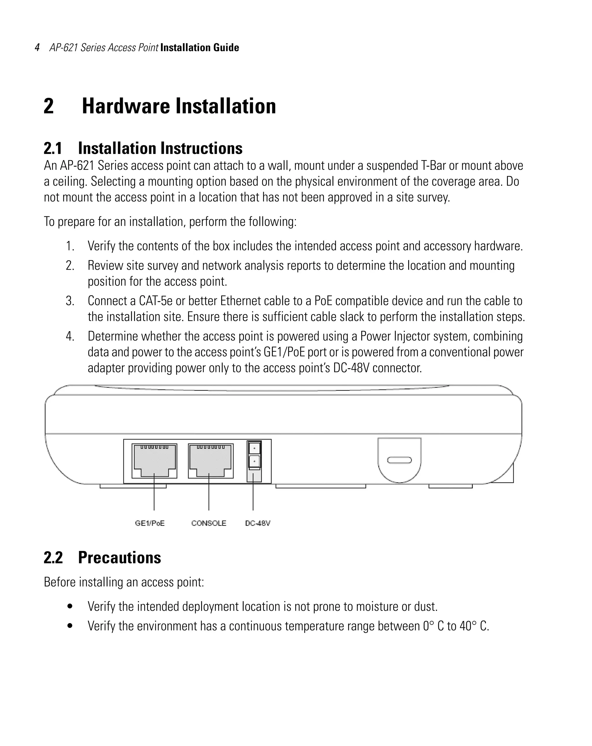
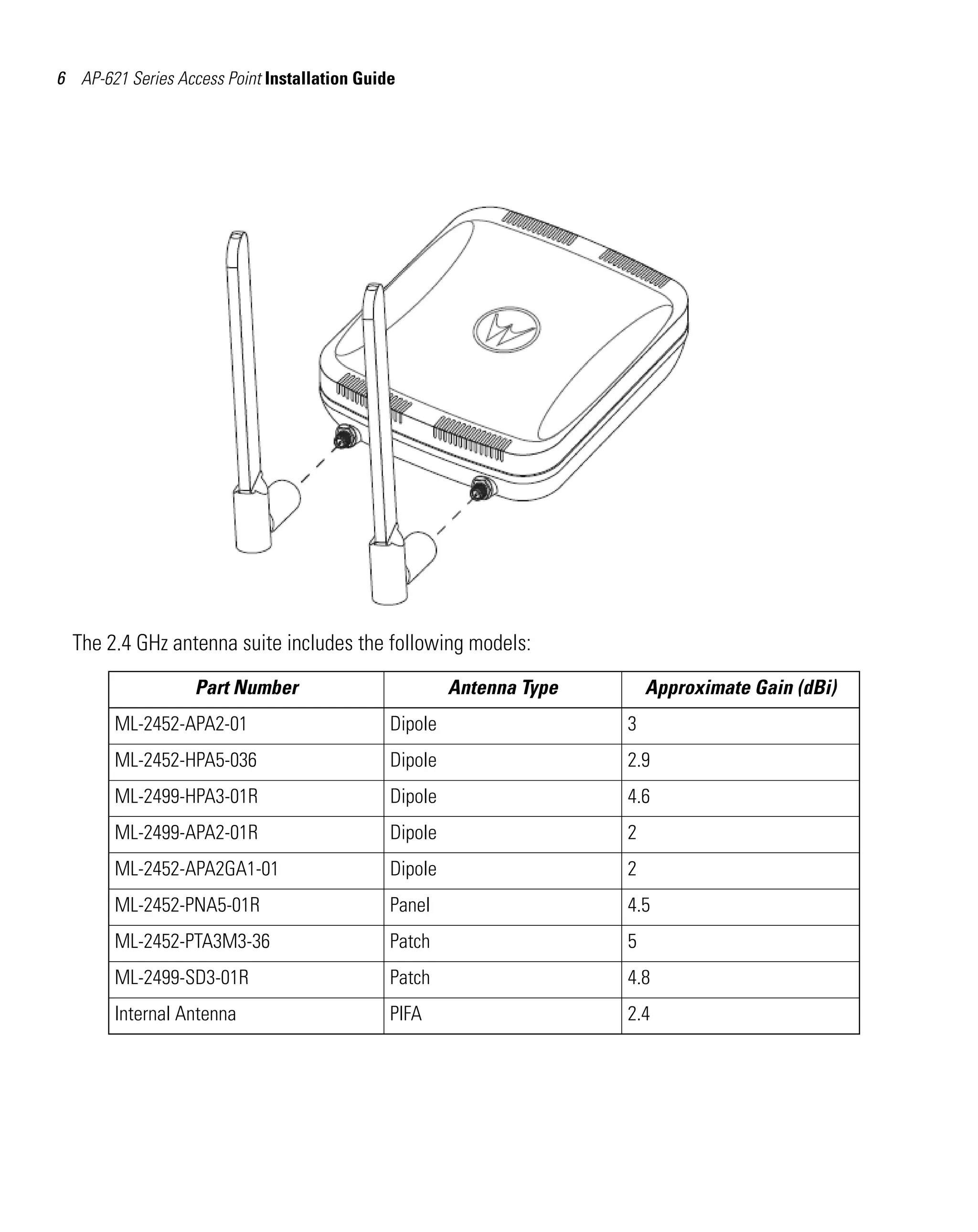
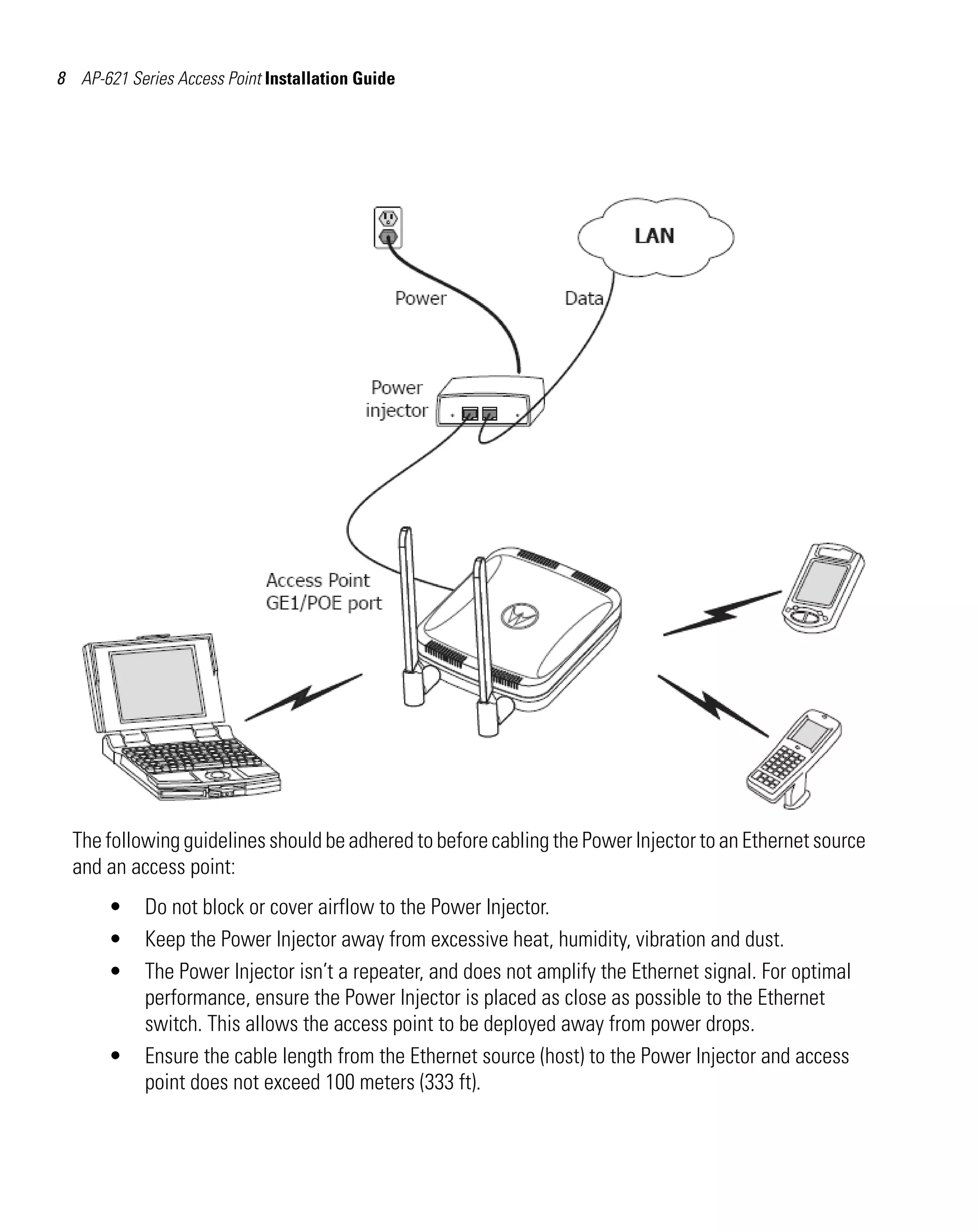
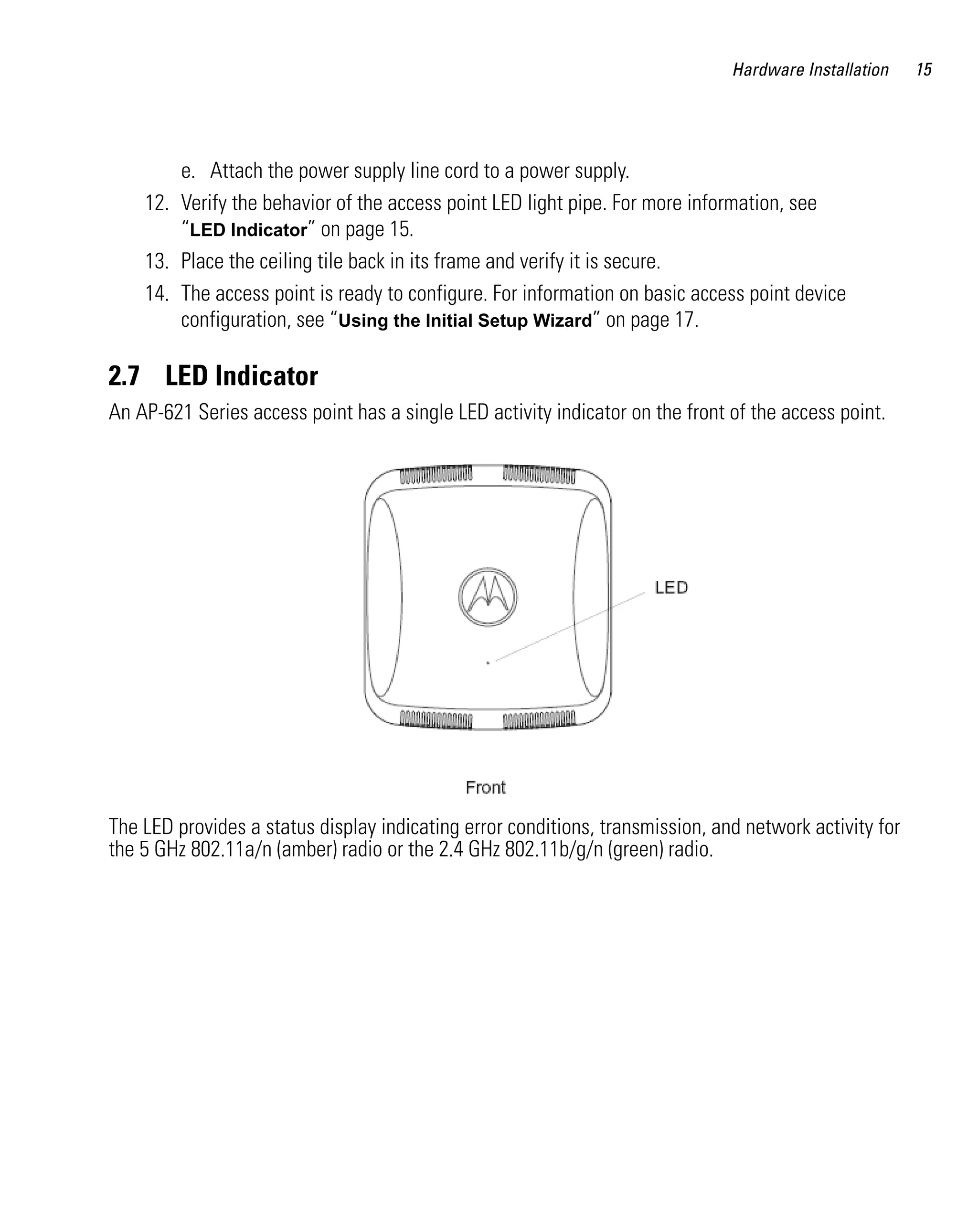
This document provides installation instructions for the AP-621 Series Access Point. It describes how to wall mount, ceiling mount, or mount above the ceiling the access point. It also discusses antenna options, using a power injector for PoE, and LED indicators. Proper placement of the access point is emphasized to maximize coverage while avoiding interference.
Motorola solutions ap622 access point installation guide (part no. 72 e 15780...Advantec Distribution
This document provides installation instructions for the AP-0622 access point. It contains information on package contents, features, and hardware installation instructions for both integrated and external antenna models. Mounting instructions are included for wall mounting and mounting on suspended ceilings. Specifications and regulatory information are also included.
This document provides installation instructions for the AP-7131 Series Access Point. It describes unpacking the access point and checking contents, guidelines for access point placement and antenna installation. It also outlines hardware installation including mounting options, connecting power, and port functions. Basic access point configuration steps are explained to complete installation. Specifications and additional resources are also referenced.
Motorola solutions ap6521 access point installation guide (part no. 72 e 1554...Advantec Distribution
The document provides installation instructions for the AP-6521 Series Access Point, which includes:
- Guidelines for mounting the access point on a wall, under a suspended ceiling, or above a ceiling.
- Details on the package contents, features, and specifications of the access point.
- Information on defining a basic configuration for the access point using an initial setup wizard.
The document provides installation instructions for the Motorola RFS6000 Series RF Switch. It includes specifications for the switch, descriptions of the LED codes on the front panel, and step-by-step instructions for hardware setup including cabling, rack mounting, connecting power and verifying installation. The introduction describes the purpose of the switch in centralizing wireless LAN configuration and management.
The document is an installation guide for the AP6522 Access Point. It provides instructions on hardware installation including wall mounting and suspended ceiling mounting for integrated antenna and external antenna models. It also lists package contents, specifications, warnings and regulatory information. The guide is intended for qualified network installers to properly setup and configure the access point.
Motorola solutions ap6522 access point installation guide wi ng 5.5 version...Advantec Distribution
This document provides installation instructions for the AP6522 Access Point. It includes guidelines for site preparation, package contents, hardware installation including wall and ceiling mounting options, antenna configuration, LED indicators, basic access point configuration, specifications, regulatory information, and support contact details. Installation requires an Ethernet switch or power supply to power the access point via Ethernet cable.
Motorola solutions ap 6521 access point installation guide - wi ng 5.5 versio...Advantec Distribution
This document provides installation instructions for the Motorola Solutions AP-6521 Access Point. It describes the contents of the AP-6521 package, features of the access point, and guidelines for installation including wall mounting, suspended ceiling installation, and above-ceiling installation. Detailed steps are provided for hardware installation and basic access point configuration. Specifications including electrical, physical, and radio characteristics are also included.
Motorola solutions ap6522 m access point installation guide wing 5.5 versio...Advantec Distribution
This document provides installation instructions for the AP 6522M Access Point. It includes warnings for safe installation, descriptions of package contents which include the access point and installation guide, and features of the access point such as LED indicators and mounting options. Installation instructions are provided for wall mounting and mounting on suspended ceilings. Specifications and regulatory information are also included.
This document provides installation instructions for the Motorola AP 7181 Access Point. It describes hardware installation including mounting the access point, connecting power and antennas. Precautions for safe installation are outlined. Grounding requirements and guidelines for deploying the network are also covered, including recommended order for installing different node types. The document concludes with initial configuration steps and regulatory compliance information.
This document provides installation instructions for the AP-8222 Access Point. It includes guidelines for site preparation, package contents, hardware installation including wall or ceiling mounting, connecting the power injector system, and basic configuration of the access point. The document also provides specifications, regulatory information, and support contact details for the AP-8222.
Motorola solutions ap 6511 access point installation guide - wi ng 5.5 versio...Advantec Distribution
This document provides installation instructions for the Motorola Solutions AP-6511 Access Point. It can be mounted on a wall or in a telco box using the included mounting plate. The access point has one Ethernet port but can be expanded using an optional 3-port module. It requires Power over Ethernet and has LED indicators to show status. Detailed instructions are provided on physical installation, configuration, specifications, regulatory information, and support contacts.
The Series 70: ePanel-1 is a Wall-Mounted Power Panel is designed to make the most of available critical facility space. Available with 42-circuit breakers.
Designed and quality built by LayerZero Power Systems in Aurora, Ohio USA.
This document provides installation instructions for the Motorola RFS7000 Series RF Switch. It describes the physical specifications, power requirements, port connections including Ethernet, USB, and console ports, as well as instructions for rack mounting and powering on the device. LED codes and patterns are explained to verify proper installation and operation.
The document provides troubleshooting guidance for common issues with wireless switches, including: switch boot up problems, IP address assignment via DHCP, connectivity issues using Telnet/SSH, slow or unresponsive web interface, faulty console port, VLAN configuration loss after reboot, access port adoption failures, mobile unit association problems, failover malfunctions, version number changes after upgrades, excessive network traffic, and memory leaks. It also describes the system status LEDs and logging mechanism to help diagnose issues.
The LayerZero Power Systems Series 70: eRDP is a web-enabled Remote Distribution Panel. Designed to maximize operator safety, the eRDP contains no exposed live parts. Brochure contains product overview, product information, and technical specifications.
This document provides installation instructions for the Motorola AP-5131 Access Point. It describes the physical specifications, electrical characteristics, and radio characteristics of the AP-5131. It then provides guidelines for installing the AP-5131, including recommended placement locations, antenna options, and connecting the necessary cables. The document aims to ensure the AP-5131 is properly installed to provide optimal wireless network coverage and performance.
This document is an installation and setup guide for the AlarmNet! 7847i/7847i-E Internet/Intranet Communication Modules. The guide contains information on mounting and wiring the module, programming it using different methods like the AlarmNet Direct website or a 7720P programming tool, registering the module, and running network diagnostics. It provides instructions for setting up the module to operate in different modes like ECP, Zone Trigger, 4204, and Two-4204 modes.
The LayerZero Series 70: eRDP-FS is a Remote Distribution Panel. Equipped with a built-in touch screen panel, eRDP-FS captures essential power quality information, including real-time waveform capture.
Designed and manufactured by LayerZero Power Systems in Aurora, Ohio USA.
This document provides installation instructions for the AP-8232 Access Point. It describes what is included in the package, features of the access point, and guidelines for hardware installation including wall or ceiling mounting and connecting power. Detailed steps are provided for installation, safety precautions, positioning the access point, and using a power injector to provide power over Ethernet. Specifications and regulatory compliance information is also included.
The document describes the Series 70 eRPP-FS remote power panel from LayerZero Power Systems. It increases reliability and safety in two ways: with a finger-safe panel board design and selective trip coordination of circuit breakers. Key features include silver-plated terminals, convection cooling, serialized critical components, power quality monitoring, Ethernet connectivity, and safety mechanisms like insulated screws and polycarbonate windows.
The document provides instructions for installing and programming the AlarmNet 7847i-L Internet Communication Module.
[1] The 7847i-L module installs inside the LYNX PLUS or LYNXR-2 control panel case and connects to the panel board and to an Ethernet network to transmit alarm signals over the Internet. [2] Programming can be done using a 7720P programming tool connected to the module or via the AlarmNet Direct website. [3] The programming prompts guide the user through setting up the module including entering account information, registering the module, and testing communications.
The AP 6532 is a dual-radio 802.11n access point that offers high throughput and WiNG 5 intelligence. It can serve as a virtual controller for up to 23 access points. Its second radio can be used for access or troubleshooting. The access point automatically optimizes power and channel selection for high quality connectivity. It is designed to optimize network availability and allow seamless roaming. It provides security including firewall, AAA RADIUS, and wireless IPS capabilities. The access point supports voice, location services, hotspots and guest access out of the box.
This document provides release notes for Cambium Network Updater Release 4.0. Key features of Release 4.0 include improved support for secure file serving, an MD5 checksum utility, and support for Windows 7 and additional Cambium device firmware versions. The release also requires Java Runtime Environment 1.5 or later and supports installation on Windows 2000/2003/XP/7 and Red Hat Enterprise Linux 4 and 5.
This white paper discusses considerations for migrating to the 802.11n wireless networking standard. It explains that 802.11n will significantly improve data rates but also affect network planning in terms of context, coverage, and capacity. Network planners must consider interference from new 40MHz channels and the site-specific effects of MIMO technology on channel planning and access point placement. The paper provides guidance on choosing the best strategy to implement 802.11n, including using the 5GHz band to take advantage of more channels and avoid tight spectrum constraints of 2.4GHz.
The document summarizes the key features and specifications of the AP-7131 tri-radio 802.11n access point. The AP-7131 is the first access point to support three radios, allowing it to simultaneously provide wireless client access, wireless mesh networking, and wireless intrusion prevention system (IPS) functionality. It offers high throughput wireless networking capabilities for voice, video, and data applications. Additional features include centralized management, wireless meshing, spectrum analysis tools, and integrated security functions like firewall, VPN, and wireless IPS. The document provides detailed specifications on the radio capabilities, operating environment, performance, management features, and security of the AP-7131.
The AP 8132 is a modular 802.11n access point with an innovative design that allows for up to two module attachments. This provides unlimited possibilities for applications and functionality beyond traditional access points. It delivers high throughput to support enterprise applications like voice and video. Its modular design reduces installation costs by leveraging the existing wireless infrastructure and eliminating the need for separate cabling for applications. The AP 8132 supports various features like voice calling, location tracking, and guest access to optimize the user experience.
The document discusses Motorola's Opportunistic Radio Link Adaptation (ORLA) algorithm, which is part of Motorola's MeshConnex routing engine. ORLA intelligently probes different data rates to select the rate that provides the best throughput. This allows for sustained high throughput even in challenging RF environments. ORLA provides benefits like faster mesh network convergence and routing. With ORLA, Motorola mesh networks can maintain high data rates for reliable connectivity and optimal customer experience.
Motorola solutions ap621 access point installation guide (part no. 72 e 15545...Advantec Distribution
This document provides installation instructions for the AP-621 Series access point. It describes the package contents, features of the access point, and guidelines for hardware installation including wall mounting, suspended ceiling mounting, and above-ceiling mounting. Precautions and considerations for optimal access point placement are also covered. Specifications for electrical, physical, and radio characteristics are listed.
Motorola solutions ap621 access point installation guide (part no. 72 e 15545...Advantec Distribution
This document provides installation instructions for the Motorola Solutions AP-621 Series Access Point. It describes the package contents, features of the access point, and guidelines for hardware installation including wall mounting, mounting under a suspended ceiling, and above-ceiling installation. Detailed instructions are provided for each installation method. Power options including a Power Injector that combines data and power over a single Ethernet cable are also discussed.
Motorola solutions ap622 access point installation guide (part no. 72 e 15780...Advantec Distribution
This document provides installation instructions for the Motorola Solutions AP-0622 wireless access point. It describes mounting the access point on a wall or ceiling for both integrated antenna and external antenna models. The document discusses package contents, hardware requirements, placement considerations, and step-by-step mounting procedures. It also provides specifications for the access point including electrical characteristics, physical dimensions, and radio capabilities.
This document provides installation instructions for the AP-7131 Series Access Point. It describes unpacking the access point and checking contents, guidelines for access point placement and antenna installation. It also outlines hardware installation including mounting options, connecting power, and port functions. Basic access point configuration steps are explained to complete installation. Specifications and additional resources are also referenced.
Motorola solutions ap622 access point installation guide (part no. 72 e 15780...Advantec Distribution
This document provides installation instructions for the Motorola Solutions AP-0622 access point. It describes how to wall mount or ceiling mount both the integrated antenna and external antenna models. The external antenna model package contents and mounting options are also outlined. The document provides specifications for the access point and regulatory information.
Motorola solutions ap7181 access point installation guide wi ng 5.5 version...Advantec Distribution
This document provides installation instructions for the Motorola Solutions AP 7181 access point. It discusses hardware installation including precautions, deployment guidelines, grounding requirements, and placement of the access point. It also covers connecting and configuring the access point, as well as regulatory information. The document is an in-depth guide for installing the AP 7181 access point hardware and ensuring proper configuration and regulatory compliance.
This document provides information about the MS-7260 mainboard, including specifications, layout, included components, installation instructions for parts like the CPU and memory, and descriptions of connectors. It includes safety instructions and regulatory compliance statements. Revisions to the document are tracked, and contact information is provided for technical support.
Motorola solutions ap7131 access point installation guide wi ng 5.5 version...Advantec Distribution
This document provides installation instructions for the Motorola Solutions AP7131 and AP7131N Access Points. It describes unpacking the access point components, selecting an installation location considering antenna coverage, mounting options including wall, ceiling and above-ceiling mounting, connecting power and network cables, and configuring the access point LED indicators. The document also provides specifications for the access point models and regulatory compliance information.
This document provides instructions for configuring a dual band 802.11ag wireless access point. It describes the hardware installation including connecting the access point to a broadband modem and Ethernet devices. It also outlines how to log in to the access point's web interface using the default IP address and password in order to configure wireless and network settings.
The document provides instructions for installing and configuring the IEEE 802.11a/n Wireless Outdoor CPE. It covers preparing for installation, connecting the hardware, mounting the CPE on a pole, and configuring the device for either AP mode or CPE mode. The installation requires connecting an Ethernet cable and power adapter, attaching optional external antennas, and accessing the web interface using the default IP and credentials. Configuration involves setting wireless parameters and security settings depending on whether the CPE is used as an access point or client.
This document provides an overview of the hardware components used in programmable logic controllers (PLCs). It describes the basic PLC components such as the CPU module, power supply module, and input/output modules. It also covers number addressing schemes for inputs and outputs. Specialized modules are discussed, including analog, temperature control, counter, positioning, and communication modules. An overview of programming software is also provided.
Motorola ap650 access point installation guide (part no. 72 e 131207-01 rev. d )Advantec Distribution
The document is an installation guide for the MAP-650 Series Thin Access Point. It contains instructions for installing both models of the access point - one with integrated antennas and one with external antennas. The guide discusses preparing the installation site, includes warnings for safe installation, and provides step-by-step instructions for mounting the access points to walls or ceilings. It also contains specifications, regulatory information, and details on customer support resources.
American Fibertek MTX46FXSLSCP User ManualJMAC Supply
Buy the American Fibertek MTX46FXSLSCP at JMAC Supply.
https://www.jmac.com/American_Fibertek_MTX_46_FX_SL_SC_POE_p/american-fibertek-mtx46fxslscp.htm?=slideshare
American Fibertek MX46FXSCPOE User ManualJMAC Supply
The document provides installation and operation instructions for American Fibertek's Series 46 PoE Ethernet Fiber Optic Transceiver. It is a 3-port switch that has two copper ports supporting 10/100BASE-TX Ethernet and one fiber port operating at 100BASE-FX. It also sources power to powered devices connected to the copper ports.
American Fibertek MTX46FXSLSTPOEHP User ManualJMAC Supply
The document provides installation and operation instructions for American Fibertek's Series 46 PoE Ethernet Fiber Optic Transceiver. It is a 3-port device that operates as an Ethernet switch and media converter, with two copper ports supporting 10/100BASE-TX Ethernet and one fiber port operating at 100BASE-FX. It also sources power to powered devices via the copper ports.
American Fibertek MTX-46-FX-SC-POE-HP User ManualJMAC Supply
Buy the American Fibertek MTX-46-FX-SC-POE-HP at JMAC Supply.
https://www.jmac.com/American_Fibertek_MTX_46_FX_SC_POE_HP_p/american-fibertek-mtx46fxscphp.htm?=slideshare
This document is the user guide for the TL-WA601G 108Mbps Wireless Access Point. It includes instructions for hardware installation, software configuration, and specifications for the device. The guide covers connecting the access point, configuring network settings, wireless settings like security and MAC filtering, and system tools for firmware, password changes, and more. It aims to easily guide users through setup and management of the wireless access point, whether familiar with networking devices or not.
Wilson signal booster 802201 ig-dbmw-071312Randall Steel
This document provides installation instructions for a Wilson Electronics dual-band mobile wireless signal booster. It describes how to install the outside antenna on the vehicle roof for optimal reception, install the inside low-profile antenna near where a phone or tablet will be used, and place the signal booster unit in a ventilated area. Lights on the booster indicate signal status, and the document provides tips for resolving issues like oscillation between the antennas.
This document is the user manual for the KE8220 Virtual VNC Console. It contains information about FCC regulations and RoHS compliance for the device. The manual provides details on the package contents, hardware setup instructions, and component descriptions to help users install and operate the KE8220 console.
Cambium Networks is an industry leader in point-to-multipoint and point-to-point wireless broadband solutions. They have shipped over 4 million nodes totaling over $1 billion to networks in more than 150 countries. Their ePMP product line provides affordable and scalable wireless access networks through features like GPS synchronization, high scalability and consistent performance, interference mitigation technology, and effective quality of service capabilities.
The VX 9000 virtualized software-based wireless LAN controller combines the power of virtualization with Motorola Solutions' WiNG Controller. It provides centralized management of wireless networks through a single interface with high scalability, flexibility and advanced wireless services. Key features include integrated network security, the advanced WiNG 5 operating system, plug-and-play deployment, simplified licensing and infinite scalability through virtualization. It supports all major hypervisors and public/private clouds for maximum deployment flexibility at low cost.
The NX 7500 integrated services platform provides comprehensive management of up to 2,048 network elements through a single interface. It allows all network infrastructure to intelligently route traffic for maximum speed and throughput without congestion. The NX 7500 offers advanced wireless LAN performance for mid-sized and campus environments with features such as plug-and-play installation, hierarchical management, smart routing, BYOD support, and integrated security services. It provides flexibility and investment protection through modular upgrades.
The document discusses the challenges retailers face in supporting increased wireless applications and next-generation Wi-Fi in stores. It introduces the Motorola AP 8200 Series as a solution that provides high-performance wireless connectivity for customers and staff. The AP 8200 Series allows easy access, security, support for 802.11ac Wi-Fi, bandwidth for applications, and performance for many users. It provides flexibility, a cost-effective upgrade to 802.11ac, and features for security, environmental monitoring, location services, and more.
The document describes the innovative features of the Motorola AP 8222 wireless access point. It has a sleek design suitable for retail, office, and other customer-facing spaces. It provides dual-band 802.11ac and 802.11n wireless connectivity at speeds up to 1.3Gbps. Key features include advanced beamforming, gap-free security, and support for bandwidth-heavy applications like video calling. The access point is centrally managed through Motorola's WiNG 5 networking operating system.
The AP 8163 is a ruggedized outdoor mesh access point designed to withstand extreme weather conditions. It has three radios - two for client access across 2.4GHz and 5GHz bands, and a third radio that can be used for wireless intrusion prevention scanning or dynamic frequency selection to avoid radar interference. The advanced WiNG 5 operating system allows the access points to self-optimize the network for best performance. Key features include powerful antennas for extended range, mesh networking for redundancy, and security features like firewalls and wireless intrusion prevention.
The document describes the features and capabilities of the Motorola AP 8122 3x3 MIMO 802.11n access point. It delivers high throughput to support enterprise applications including voice and HD video using 802.11n technology with standard 802.3af PoE. It has advanced features like load balancing, pre-emptive roaming, and dual band radios to increase network reliability, resilience, and security. The access point also supports advanced wireless capabilities such as voice over wireless, location services, and guest access controls.
The document describes the innovative features of the AP 7532 wireless access point. It provides the highest wireless speeds available with 3x3 MIMO and 256 QAM modulation on both 2.4GHz and 5GHz radios. It has a dual radio 802.11ac/802.11n design that provides a upgrade path to 1.3Gbps 802.11ac speeds while maintaining support for existing devices. It offers various advanced features like load balancing, security, sensor support and quality of service for voice. The access point is designed to deliver maximum performance at a low cost.
The AP 7502 is a dual-band 802.11ac wireless access point designed for installation in small spaces like hotel rooms. It has a compact wall-mount design, supports the latest WiFi standards, and includes features to ensure reliable connectivity even in challenging environments. Setup and management are simplified through zero-touch provisioning and both standalone and controller-based operation modes.
The document describes the innovative features of the AP 7522 wireless access point. It provides dual-band 802.11ac and 802.11n radios for high performance WiFi. It offers internal or external antenna options and can function as both an access point and wireless sensor. The access point provides security, load balancing, and other features to support mission critical applications on the wireless network.
Essentials of Automations: The Art of Triggers and Actions in FMESafe Software
In this second installment of our Essentials of Automations webinar series, we’ll explore the landscape of triggers and actions, guiding you through the nuances of authoring and adapting workspaces for seamless automations. Gain an understanding of the full spectrum of triggers and actions available in FME, empowering you to enhance your workspaces for efficient automation.
We’ll kick things off by showcasing the most commonly used event-based triggers, introducing you to various automation workflows like manual triggers, schedules, directory watchers, and more. Plus, see how these elements play out in real scenarios.
Whether you’re tweaking your current setup or building from the ground up, this session will arm you with the tools and insights needed to transform your FME usage into a powerhouse of productivity. Join us to discover effective strategies that simplify complex processes, enhancing your productivity and transforming your data management practices with FME. Let’s turn complexity into clarity and make your workspaces work wonders!
Why You Should Replace Windows 11 with Nitrux Linux 3.5.0 for enhanced perfor...SOFTTECHHUB
The choice of an operating system plays a pivotal role in shaping our computing experience. For decades, Microsoft's Windows has dominated the market, offering a familiar and widely adopted platform for personal and professional use. However, as technological advancements continue to push the boundaries of innovation, alternative operating systems have emerged, challenging the status quo and offering users a fresh perspective on computing.
One such alternative that has garnered significant attention and acclaim is Nitrux Linux 3.5.0, a sleek, powerful, and user-friendly Linux distribution that promises to redefine the way we interact with our devices. With its focus on performance, security, and customization, Nitrux Linux presents a compelling case for those seeking to break free from the constraints of proprietary software and embrace the freedom and flexibility of open-source computing.
In his public lecture, Christian Timmerer provides insights into the fascinating history of video streaming, starting from its humble beginnings before YouTube to the groundbreaking technologies that now dominate platforms like Netflix and ORF ON. Timmerer also presents provocative contributions of his own that have significantly influenced the industry. He concludes by looking at future challenges and invites the audience to join in a discussion.
“An Outlook of the Ongoing and Future Relationship between Blockchain Technologies and Process-aware Information Systems.” Invited talk at the joint workshop on Blockchain for Information Systems (BC4IS) and Blockchain for Trusted Data Sharing (B4TDS), co-located with with the 36th International Conference on Advanced Information Systems Engineering (CAiSE), 3 June 2024, Limassol, Cyprus.
Unlock the Future of Search with MongoDB Atlas_ Vector Search Unleashed.pdfMalak Abu Hammad
Discover how MongoDB Atlas and vector search technology can revolutionize your application's search capabilities. This comprehensive presentation covers:
* What is Vector Search?
* Importance and benefits of vector search
* Practical use cases across various industries
* Step-by-step implementation guide
* Live demos with code snippets
* Enhancing LLM capabilities with vector search
* Best practices and optimization strategies
Perfect for developers, AI enthusiasts, and tech leaders. Learn how to leverage MongoDB Atlas to deliver highly relevant, context-aware search results, transforming your data retrieval process. Stay ahead in tech innovation and maximize the potential of your applications.
#MongoDB #VectorSearch #AI #SemanticSearch #TechInnovation #DataScience #LLM #MachineLearning #SearchTechnology
Best 20 SEO Techniques To Improve Website Visibility In SERPPixlogix Infotech
Boost your website's visibility with proven SEO techniques! Our latest blog dives into essential strategies to enhance your online presence, increase traffic, and rank higher on search engines. From keyword optimization to quality content creation, learn how to make your site stand out in the crowded digital landscape. Discover actionable tips and expert insights to elevate your SEO game.
Unlocking Productivity: Leveraging the Potential of Copilot in Microsoft 365, a presentation by Christoforos Vlachos, Senior Solutions Manager – Modern Workplace, Uni Systems
GraphSummit Singapore | The Future of Agility: Supercharging Digital Transfor...Neo4j
Leonard Jayamohan, Partner & Generative AI Lead, Deloitte
This keynote will reveal how Deloitte leverages Neo4j’s graph power for groundbreaking digital twin solutions, achieving a staggering 100x performance boost. Discover the essential role knowledge graphs play in successful generative AI implementations. Plus, get an exclusive look at an innovative Neo4j + Generative AI solution Deloitte is developing in-house.
Infrastructure Challenges in Scaling RAG with Custom AI modelsZilliz
Building Retrieval-Augmented Generation (RAG) systems with open-source and custom AI models is a complex task. This talk explores the challenges in productionizing RAG systems, including retrieval performance, response synthesis, and evaluation. We’ll discuss how to leverage open-source models like text embeddings, language models, and custom fine-tuned models to enhance RAG performance. Additionally, we’ll cover how BentoML can help orchestrate and scale these AI components efficiently, ensuring seamless deployment and management of RAG systems in the cloud.
Removing Uninteresting Bytes in Software FuzzingAftab Hussain
Imagine a world where software fuzzing, the process of mutating bytes in test seeds to uncover hidden and erroneous program behaviors, becomes faster and more effective. A lot depends on the initial seeds, which can significantly dictate the trajectory of a fuzzing campaign, particularly in terms of how long it takes to uncover interesting behaviour in your code. We introduce DIAR, a technique designed to speedup fuzzing campaigns by pinpointing and eliminating those uninteresting bytes in the seeds. Picture this: instead of wasting valuable resources on meaningless mutations in large, bloated seeds, DIAR removes the unnecessary bytes, streamlining the entire process.
In this work, we equipped AFL, a popular fuzzer, with DIAR and examined two critical Linux libraries -- Libxml's xmllint, a tool for parsing xml documents, and Binutil's readelf, an essential debugging and security analysis command-line tool used to display detailed information about ELF (Executable and Linkable Format). Our preliminary results show that AFL+DIAR does not only discover new paths more quickly but also achieves higher coverage overall. This work thus showcases how starting with lean and optimized seeds can lead to faster, more comprehensive fuzzing campaigns -- and DIAR helps you find such seeds.
- These are slides of the talk given at IEEE International Conference on Software Testing Verification and Validation Workshop, ICSTW 2022.
Threats to mobile devices are more prevalent and increasing in scope and complexity. Users of mobile devices desire to take full advantage of the features
available on those devices, but many of the features provide convenience and capability but sacrifice security. This best practices guide outlines steps the users can take to better protect personal devices and information.
For the full video of this presentation, please visit: https://www.edge-ai-vision.com/2024/06/building-and-scaling-ai-applications-with-the-nx-ai-manager-a-presentation-from-network-optix/
Robin van Emden, Senior Director of Data Science at Network Optix, presents the “Building and Scaling AI Applications with the Nx AI Manager,” tutorial at the May 2024 Embedded Vision Summit.
In this presentation, van Emden covers the basics of scaling edge AI solutions using the Nx tool kit. He emphasizes the process of developing AI models and deploying them globally. He also showcases the conversion of AI models and the creation of effective edge AI pipelines, with a focus on pre-processing, model conversion, selecting the appropriate inference engine for the target hardware and post-processing.
van Emden shows how Nx can simplify the developer’s life and facilitate a rapid transition from concept to production-ready applications.He provides valuable insights into developing scalable and efficient edge AI solutions, with a strong focus on practical implementation.
Goodbye Windows 11: Make Way for Nitrux Linux 3.5.0!SOFTTECHHUB
As the digital landscape continually evolves, operating systems play a critical role in shaping user experiences and productivity. The launch of Nitrux Linux 3.5.0 marks a significant milestone, offering a robust alternative to traditional systems such as Windows 11. This article delves into the essence of Nitrux Linux 3.5.0, exploring its unique features, advantages, and how it stands as a compelling choice for both casual users and tech enthusiasts.
Full-RAG: A modern architecture for hyper-personalizationZilliz
Mike Del Balso, CEO & Co-Founder at Tecton, presents "Full RAG," a novel approach to AI recommendation systems, aiming to push beyond the limitations of traditional models through a deep integration of contextual insights and real-time data, leveraging the Retrieval-Augmented Generation architecture. This talk will outline Full RAG's potential to significantly enhance personalization, address engineering challenges such as data management and model training, and introduce data enrichment with reranking as a key solution. Attendees will gain crucial insights into the importance of hyperpersonalization in AI, the capabilities of Full RAG for advanced personalization, and strategies for managing complex data integrations for deploying cutting-edge AI solutions.
5. AP621 IG.book Page 1 Tuesday, September 20, 2011 3:18 PM
Introduction 1
1 Introduction
The AP-621 Series access point, component of Motorola Solutions Wireless Controller System, links
wireless 802.11a/b/g/n devices to the controller, enabling the growth of your wireless network with
a cost-effective alternative to standard access points. The AP-621 Series is an enterprise class
802.11n access point, installed in minutes anywhere a CAT-5e (or better) cable is located.
An AP-621 Series access point operates in dependent mode only, and requires adoption and
management by a Motorola Solutions controller to receive its configuration.
An AP-621 Series access point ships with a single dual-band radio supporting the
802.11a/b/g/n radio bands. For more information on available SKUs, refer to the following:
Part Number Description
AP-0621-60010-US 802.11a/b/g/n single radio, integrated antenna, standard
power, United States model
AP-0621-60020-US 802.11a/b/g/n single radio, external antenna, standard
power, United States model
AP-0621-60010-WR 802.11a/b/g/n single radio, integrated antenna, standard
power, World Wide model
AP-0621-60020-WR 802.11a/b/g/n single radio, external antenna, standard
power, World Wide model
The AP-621 Series access point is approved under MODEL: NCAP-500.
Motorola Solutions recommends the access point receive power and transfer data through the same
CAT-5e (or better) Ethernet cable using a Motorola Solutions Power Injector. The Power Injector
(Part No. AP-PSBIAS-2P2-AFR) is an 802.3af PoE injector. For information, see “Power Injector
System” on page 7.
A separate power supply (Part No. PWRS-147376-01R) is also available if you do not wish to use a
Power Injector. This standard power supply just supplies power to the access point’s power connector
and does not converge power and Ethernet within a single cable connection.
The AP-621 Series access point requires adoption by a Motorola Solutions controller to receive its
configurations. For information, see “Defining a Basic Configuration” on page 17.
6. AP621 IG.book Page 2 Tuesday, September 20, 2011 3:18 PM
2 AP-621 Series Access Point Installation Guide
1.1 Document Conventions
The following graphical alerts are used in this guide to indicate notable situations:
NOTE Tips, hints, or special requirements that you should take note of.
!
CAUTION Care is required. Disregarding a caution can result in data loss or
equipment malfunction.
WARNING! Indicates a condition or procedure that could result in personal injury or
equipment damage.
1.2 Warnings
• Read all installation instructions and site survey reports, and verify correct equipment
installation before connecting the access point.
• Verify any device connected to this unit is properly wired and grounded.
• Verify there is adequate ventilation around the device, and ambient temperatures meet
equipment operation specifications.
7. AP621 IG.book Page 3 Tuesday, September 20, 2011 3:18 PM
Introduction 3
1.3 Site Preparation
• Consult your site survey and network analysis to determine specific equipment placement,
power drops etc.
• Assign installation responsibility to the appropriate personnel.
• Identify and document where all installed components are located.
• Ensure adequate, dust-free ventilation to all installed equipment.
• Prepare Ethernet port connections.
• Verify cabling is within the maximum 100 meter allowable length.
1.4 Package Contents
The access point ships with the following:
• One AP-621 Series access point
• Installation Guide (This Guide)
• Rubber Wall Mount Spacers (4)
• LED light pipe and badge
• Wall mount screw and anchor kit
1.5 Features
• One RJ-45 console connector
• One RJ-45 Ethernet connector
• LED Indicators
• Safety wire tie point
• Wall mount slots
• Clips for suspended T-Bar mounting
• DC power connector
An AP-621 Series access point has one RJ-45 connector supporting an 10/100/1000 Ethernet port
connection and requires 802.3af compliant power from an external source.
The access point contains runtime firmware which enables the unit to boot after either a power up
or a watchdog reset. The runtime firmware on the access point can be updated via the Ethernet
interface.
8. AP621 IG.book Page 4 Tuesday, September 20, 2011 3:18 PM
4 AP-621 Series Access Point Installation Guide
2 Hardware Installation
2.1 Installation Instructions
An AP-621 Series access point can attach to a wall, mount under a suspended T-Bar or mount above
a ceiling. Selecting a mounting option based on the physical environment of the coverage area. Do
not mount the access point in a location that has not been approved in a site survey.
To prepare for an installation, perform the following:
1. Verify the contents of the box includes the intended access point and accessory hardware.
2. Review site survey and network analysis reports to determine the location and mounting
position for the access point.
3. Connect a CAT-5e or better Ethernet cable to a PoE compatible device and run the cable to
the installation site. Ensure there is sufficient cable slack to perform the installation steps.
4. Determine whether the access point is powered using a Power Injector system, combining
data and power to the access point’s GE1/PoE port or is powered from a conventional power
adapter providing power only to the access point’s DC-48V connector.
2.2 Precautions
Before installing an access point:
• Verify the intended deployment location is not prone to moisture or dust.
• Verify the environment has a continuous temperature range between 0° C to 40° C.
9. AP621 IG.book Page 5 Tuesday, September 20, 2011 3:18 PM
Hardware Installation 5
2.3 Access Point Placement
For optimal performance, install the access point away from transformers, heavy-duty motors,
fluorescent lights, microwave ovens, refrigerators and other industrial equipment. Signal loss can
occur when metal, concrete, walls or floors block transmission. Install the access point in an open
area or add access points as needed to improve coverage.
Antenna coverage is analogous to lighting. Users might find an area lit from far away to be not bright
enough. An area lit sharply might minimize coverage and create dark areas. Uniform antenna
placement in an area (like even placement of a light bulb) provides even, efficient coverage.
Place the access point using the following guidelines:
• Install the access point at an ideal height of 10 feet from the ground.
• Orient the access point antennas vertically for best reception.
• Point the access point antennas downward if attaching to the ceiling (external antenna
models only).
To maximize the access point’s radio coverage area, Motorola Solutions recommends conducting a
site survey to define and document radio interference obstacles before installing the access point.
2.3.1 Antenna Options
Motorola Solutions supports two antenna suites for the single radio, dual-band, AP-621 Series access
point. One antenna suite supporting the 2.4 GHz band, and another antenna suite supporting the 5
GHz band. Select an antenna best suited to the intended operational environment of your access
point.
10. AP621 IG.book Page 6 Tuesday, September 20, 2011 3:18 PM
6 AP-621 Series Access Point Installation Guide
The 2.4 GHz antenna suite includes the following models:
Part Number Antenna Type Approximate Gain (dBi)
ML-2452-APA2-01 Dipole 3
ML-2452-HPA5-036 Dipole 2.9
ML-2499-HPA3-01R Dipole 4.6
ML-2499-APA2-01R Dipole 2
ML-2452-APA2GA1-01 Dipole 2
ML-2452-PNA5-01R Panel 4.5
ML-2452-PTA3M3-36 Patch 5
ML-2499-SD3-01R Patch 4.8
Internal Antenna PIFA 2.4
11. AP621 IG.book Page 7 Tuesday, September 20, 2011 3:18 PM
Hardware Installation 7
The 5 GHz antenna suite includes the following models:
Part Number Antenna Type Approximate Gain (dBi)
ML-2452-APA2-01 Dipole 5
ML-2452-HPA5-036 Dipole 4.9
ML-5299-APA1-01R Dipole 2
ML-5299-HPA1-01R Dipole 5
ML-2452-APA2GA1-01 Dipole 1
ML-2452-PNA5-01R Panel 5
ML-2452-PTA3M3-36 Patch 3
ML-5299-PTA1-0R Patch 5
Internal Antenna PIFA 5.3
For a more exhaustive overview of the antennas and associated components supported by the
Motorola Solutions access point family, refer to the Enterprise Wireless LAN Antenna Specification
Guide available at http://support.symbol.com/support/product/manuals.do.
2.3.2 Power Injector System
The access point can receive power via an Ethernet cable connected to the GE1/PoE port.
When users purchase a WLAN solution, they often need to place access points in obscure locations.
In the past, a dedicated power source was required for each access point in addition to the Ethernet
infrastructure. This often required an electrical contractor to install power drops at each access point
location. The Power Injector merges power and Ethernet into one cable, reducing the burden of
installation and allowing optimal access point placement in respect to the intended coverage area.
The Power Injector (Part No. AP-PSBIAS-2P2-AFR) is an 802.3af PoE injector. The access point can
only use a Power Injector when connecting to the access point’s GE1/PoE port. The Power Injector is
separately ordered and not shipped with the access point. A separate Power Injector is required for
each access point comprising the network.
The Power Injector has no On/Off power switch. The Injector receives power and is ready for device
connection and operation as soon as AC power is applied. Refer to the guide shipped with the Power
Injector for a description of the device’s LEDs. The Power Injector can be installed free standing, on
an even horizontal surface or wall mounted using the Power Injector’s wall mounting key holes.
12. AP621 IG.book Page 8 Tuesday, September 20, 2011 3:18 PM
8 AP-621 Series Access Point Installation Guide
The following guidelines should be adhered to before cabling the Power Injector to an Ethernet source
and an access point:
• Do not block or cover airflow to the Power Injector.
• Keep the Power Injector away from excessive heat, humidity, vibration and dust.
• The Power Injector isn’t a repeater, and does not amplify the Ethernet signal. For optimal
performance, ensure the Power Injector is placed as close as possible to the Ethernet
switch. This allows the access point to be deployed away from power drops.
• Ensure the cable length from the Ethernet source (host) to the Power Injector and access
point does not exceed 100 meters (333 ft).
13. AP621 IG.book Page 9 Tuesday, September 20, 2011 3:18 PM
Hardware Installation 9
CAUTION To avoid problematic performance and restarts, disable PoE from a
!
wired controller port connected to an access point if mid-span power
sourcing equipment (PSE) is used between the two, regardless of the
manufacturer.
CAUTION Ensure AC power is supplied to the Power Injector using an AC cable
! with an appropriate ground connection approved for the country of
operation.
NOTE If not using the Power Injector to power the access point, the only other
approved power solution is the standard power supply (Part Number
PWRS-147376-01R). The standard power supply does not converge data
and power in one cable, and requires a separate data Ethernet
connection in addition to a power connection. This product is intended to
be supplied by a listed power adapter marked “Class 2” or “L.P.S” (or
“Limited Power Source”) and rated from 48Vdc, 0.27A minimum.
2.4 Wall Mount Installation
To support wall mount installations, the access point is fastened directly to a flat wall surface. The
wall should be of gypsum board, plaster, wood or concrete in composition.
CAUTION An access point should be wall mounted to concrete or plaster-
! wall-board (dry wall) only. Do not wall mount the access point to
combustible surfaces.
To install the access point to a wall:
1. Orient the access point by either its width or length.
2. Mark the mounting surface at the target screw insertion points.
3. At each point, drill a hole in the wall, insert an anchor, screw into the anchor the wall
mounting screw and stop when there is 1mm between the screw head and the wall.
If pre-drilling a hole, the recommended hole size is 2.8mm (0.11in.) if the screws are going
directly into the wall and 6mm (0.23in.) if wall anchors are being used.
4. If required, install and attach a security cable to the access point lock port.
14. AP621 IG.book Page 10 Tuesday, September 20, 2011 3:18 PM
10 AP-621 Series Access Point Installation Guide
5. Attach the antennas to their correct connectors.
For information on available antennas, see “Antenna Options” on page 5.
6. Place the large center opening of each of the mount slots over the screw heads.
7. Slide the access point down along the mounting surface to hang the mount slots on the
screw heads
8. Cable the access point using either the Power Injector or an approved line cord and power
supply.
CAUTION Do not connect to the power source until the cabling of the access
!
point is complete. Ensure PoE is not connected to the access point’s
console connector or risk rendering the console connector
permanently inoperable.
For Motorola Power Injector installations:
a. Connect a RJ-45 CAT5e (or CAT6) Ethernet cable between the network data supply (host)
and the Power Injector Data In connector.
b. Connect a RJ-45 CAT5e (or CAT6) Ethernet cable between the Power Injector Data &
Power Out connector and the access point GE1/PoE port.
c. Ensure the cable length from the Ethernet source (host) to the Power Injector and
access point does not exceed 100 meters (333 ft). The Power Injector has no On/Off
power switch. The Power Injector receives power as soon as AC power is applied. For
more information on using the Power Injector, see “LED Indicator” on page 15.
For power adapter (Part Number PWRS-147376-01R) and line cord installations:
a. Connect a RJ-45 CAT5e (or CAT6) Ethernet cable between the network data supply (host)
and the access point’s GE1/PoE.
b. Verify the power adapter is correctly rated according the country of operation.
c. Connect the power supply line cord to the power adapter.
d. Attach the power adapter cable to the DC-48V power connector on the access point.
e. Attach the power supply line cord to a power supply.
9. Verify the behavior of the LEDs. For more information, see “LED Indicator” on page 15.
15. AP621 IG.book Page 11 Tuesday, September 20, 2011 3:18 PM
Hardware Installation 11
10. The access point is ready to configure. For information on basic access point device
configuration, see “Defining a Basic Configuration” on page 17.
2.5 Suspended Ceiling T-Bar Installation
A suspended ceiling mount requires holding the access point up against the T-bar of a suspended
ceiling grid and twisting the access point chassis onto the T-bar.
To install the access point on a ceiling T-bar:
1. If desired, install and attach a security cable to the access point lock port.
2. If using an external antenna model, attach the antennas to their correct connectors.
3. For more information on the antenna options available to the access point, see “Antenna
Options” on page 11.
4. Cable the access point using either the Power Injector solution or an approved line cord and
power supply.
CAUTION Do not connect to the power source until the cabling of the access
!
point is complete. Ensure PoE is not connected to the access point’s
console connector or risk rendering the console connector
permanently inoperable.
For Power Injector installations:
a. Connect a RJ-45 CAT5e (or CAT6) Ethernet cable between the network data supply (host)
and the Power Injector Data In connector.
b. Connect a RJ-45 CAT5e (or CAT6) Ethernet cable between the Power Injector Data &
Power Out connector and the access point’s GE1/PoE port.
c. Ensure the cable length from the Ethernet source (host) to the Power Injector and
access point does not exceed 100 meters (333 ft). The Power Injector has no On/Off
power switch. The Power Injector receives power as soon as AC power is applied. For
more information on using the Power Injector, see “Power Injector System” on page 7.
For power adapter (Part Number PWRS-147376-01R) and line cord installations:
a. Connect a RJ-45 Ethernet cable between the network data supply (host) and the access
point’s GE1/PoE port.
b. Verify the power adapter is correctly rated according the country of operation.
16. AP621 IG.book Page 12 Tuesday, September 20, 2011 3:18 PM
12 AP-621 Series Access Point Installation Guide
c. Connect the power supply line cord to the power adapter.
d. Attach the power adapter cable to the DC-48V power connector on the access point.
e. Attach the power supply line cord to a power supply.
5. Verify the behavior of the access point LEDs. For more information, see “LED Indicator” on
page 15.
6. Align the bottom of the ceiling T-bar with the back of the access point.
7. Orient the access point chassis by its length and the length of the ceiling T-bar.
8. Rotate the access point chassis 45 degrees clockwise.
9. Push the back of the access point chassis on to the bottom of the ceiling T-bar.
10. Rotate the access point chassis 45 degrees counter-clockwise. The clips click as they fasten
to the T-bar.
11. Verify the behavior of the LEDs. For more information, see “LED Indicator” on page 15.
12. The access point is ready to configure. For information on basic access point device
configuration, see “Defining a Basic Configuration” on page 17.
17. AP621 IG.book Page 13 Tuesday, September 20, 2011 3:18 PM
Hardware Installation 13
2.6 Above the Ceiling (Plenum) Installation
An above the ceiling installation requires placing the access point above a suspended ceiling and
installing the provided light pipe under the ceiling tile for viewing the status LED of the unit. An above
the ceiling installation enables installations compliant with drop ceilings, suspended ceilings and
industry standard tiles from .625 to .75 inches thick.
NOTE The access point is Plenum rated to UL2043 and NEC1999 to support
above the ceiling installations. To ensure UL compliance and proper
access point operation within the Air Handling Plenum, the access point
must be installed with the bottom surface of the unit in contact with the
un-finished surface of the ceiling tile. Placing the product on the ceiling
tile will facilitate the positioning of the light pipe. Placement of the
product in the Air Handling Plenum off of, or away from, the unfinished
surface of the ceiling tile is not UL approved and certification of UL2043
compliance would be void in that case.
CAUTION Motorola Solutions does not recommend mounting the access point
!
directly to suspended ceiling tile with a thickness less than 12.7mm
(0.5in.) or a suspended ceiling tile with an unsupported span greater
than 660mm (26in.).
The mounting hardware required to install the access point above a ceiling consists of:
• Light pipe
• Badge for light pipe
• Decal for badge
To install the access point above a ceiling:
1. If possible, remove the adjacent ceiling tile from its frame and place it aside.
2. If required, install and attach a security cable to the access point’s lock port.
3. Mark a point on the finished side of the tile where the light pipe is to be located.
4. Create a light pipe path hole in the target position on the ceiling tile.
5. Use a drill to make a hole in the tile the approximate size of the access point LED light pipe.
CAUTION Motorola Solutions recommends care be taken not to damage the
! finished surface of the ceiling tile when creating the light pipe hole
and installing the light pipe.
18. AP621 IG.book Page 14 Tuesday, September 20, 2011 3:18 PM
14 AP-621 Series Access Point Installation Guide
6. Remove the light pipe’s rubber stopper (from the access point) before installing the light
pipe.
7. Connect the light pipe to the bottom of the access point. Align the tabs and rotate
approximately 90 degrees. Do not over tighten.
8. Fit the light pipe into hole in the tile from its unfinished side.
9. Place the decal on the back of the badge and slide the badge onto the light pipe from the
finished side of the tile.
10. Attach the antennas to their correct connectors.
For information on the antennas available to the access point, see “Antenna Options” on
page 5.
11. Align the ceiling tile into its former ceiling space.
13. Cable the access point using either the Power Injector solution or an approved line cord and
power supply.
CAUTION Do not connect to the power source until the cabling of the access
!
point is complete. Ensure PoE is not connected to the access point’s
console connector or risk rendering the console connector
permanently inoperable
For Power Injector installations:
a. Connect a RJ-45 CAT5e (or CAT6) Ethernet cable between the network data supply (host)
and the Power Injector Data In connector.
b. Connect a RJ-45 CAT5e (or CAT6) Ethernet cable between the Power Injector Data &
Power Out connector and the access point’s GE1/PoE port.
c. Ensure the cable length from the Ethernet source (host) to the Power Injector and
access point does not exceed 100 meters (333 ft). The Power Injector has no On/Off
power switch. The Power Injector receives power as soon as AC power is applied. For
more information on using the Power Injector, see “Power Injector System” on page 7.
For power adapter (Part Number PWRS-147376-01R) and line cord installations:
a. Connect a RJ-45 Ethernet cable between the network data supply (host) and the access
point’s GE1/PoE port.
b. Verify the power adapter is correctly rated according the country of operation.
c. Connect the power supply line cord to the power adapter.
d. Attach the power adapter cable to the DC-48V power connector on the access point.
19. AP621 IG.book Page 15 Tuesday, September 20, 2011 3:18 PM
Hardware Installation 15
e. Attach the power supply line cord to a power supply.
12. Verify the behavior of the access point LED light pipe. For more information, see
“LED Indicator” on page 15.
13. Place the ceiling tile back in its frame and verify it is secure.
14. The access point is ready to configure. For information on basic access point device
configuration, see “Using the Initial Setup Wizard” on page 17.
2.7 LED Indicator
An AP-621 Series access point has a single LED activity indicator on the front of the access point.
The LED provides a status display indicating error conditions, transmission, and network activity for
the 5 GHz 802.11a/n (amber) radio or the 2.4 GHz 802.11b/g/n (green) radio.
20. AP621 IG.book Page 16 Tuesday, September 20, 2011 3:18 PM
16 AP-621 Series Access Point Installation Guide
Task 5 GHz Activity LED (Amber) 2.4 GHz Activity LED (Green)
Unadopted Off Blinking 5 times per second
Normal • If this radio band is enabled: • If this radio band is enabled:
Operation Blink at 5 second interval Blink at 5 second interval
• If this radio band is disabled: • If this radio band is disabled:
Off Off
• If there is activity on this band: • If there is activity on this band:
Blink at a 1Hz Blink at a 1Hz
Firmware On Off
Update
Locate AP Blink at 5Hz Blink at 5Hz
Mode
21. AP621 IG.book Page 17 Tuesday, September 20, 2011 3:18 PM
Defining a Basic Configuration 17
3 Defining a Basic Configuration
An AP-621 Series access point receives its configuration when adopted by a Motorola Solutions RFS
controller. Adoption is the process an access point uses to discover controllers available in the
network, pick the most desirable controller, establish an association and obtain a configuration.
For information on preparing a controller for AP-621 Series access point adoption, refer to the
Motorola Solutions Wireless Services Controller System Reference Guide, available at
http://support.symbol.com/support/product/manuals.do.
22. AP621 IG.book Page 18 Tuesday, September 20, 2011 3:18 PM
18 AP-621 Series Access Point Installation Guide
4 Specifications
4.1 Electrical Characteristics
An AP-621 Series access point has the following electrical characteristics:
Max DC Power 12.95W (270mA@48V)
Consumption
4.2 Physical Characteristics
An AP-621 Series access point has the following physical characteristics:
Dimensions 6.0 (Length) x 5.5 (Width) x 1.63 (Tall) - Inches
152.4 (Length) x 139.7 (Width) x 41.1 (Tall) - Millimeters
Housing Plastic
Weight 0.60 lbs/0.272 kg
Operating 32°F to 104°F/0°C to 40°C
Temperature
Storage Temperature -40°F to 158°F/-40°C to 70°C
Operating Humidity 5 to 95% Relative Humidity non-condensing
Storage Humidity 85% Relative Humidity non-condensing
Operating Altitude 8,000 ft @ 28°C
(max)
Storage Altitude 30,000 ft @ 12°C
(max)
Electrostatic +/-15kV Air and +/-8kV Contact @ 50% Relative Humidity
Discharge
23. AP621 IG.book Page 19 Tuesday, September 20, 2011 3:18 PM
Specifications 19
4.3 Radio Characteristics
An AP-621 Series access point has the following radio characteristics:
Radio Characteristic AP-621 Standard Power
Operating Channel (2.4 GHz) Channel 1 to 13 (2412 to 2472 MHz)
Operating Channel (5.2 GHz) Channels 36 to 48; channels 149 - 165
802.11a Data Rates 6, 9, 12, 18, 24, 36, 48, 54 Mbps
802.11b Data Rates 1, 2, 5.5, 11 Mbps
802.11g Data Rates 6, 9, 12, 18, 24, 36, 48, 54 Mbps
802.11n Data Rates MCS0 to MCS15 at both HT20 and HT40 modes
Max Transmit Power (2.4GHz) 24 dBm
Max Transmit Power (5.2 GHz) 20 dBm
Transmit Power Adjustment 1 dB
24. AP621 IG.book Page 20 Tuesday, September 20, 2011 3:18 PM
20 AP-621 Series Access Point Installation Guide
5 Regulatory Information
5.1 Regulatory Overview
This device is approved under the Motorola Solutions brand.
This guide applies to Part Numbers AP-0621-60010-US, AP-0621-60020-US, AP-0621-60010-WR, and
AP-0621-60020-WR. AP-621 Series access points are approved under MODEL: NCAP-500.
All Motorola Solutions devices are designed to be compliant with rules and regulations in locations
they are sold and will be labeled as required.
Any changes or modifications to Motorola Solutions equipment, not expressly approved by Motorola
Solutions, could void the user’s authority to operate the equipment.
Motorola Solutions Access Points must be professionally installed and configured so that the Radio
Frequency Output Power will not exceed the maximum allowable limit for the country of operation.
Antennas: Use only the supplied or an approved replacement antenna. Unauthorized antennas,
modifications, or attachments could cause damage and may violate regulations. Use of an
unapproved antenna is illegal under FCC regulations subjecting the end user to fines and equipment
seizure.
5.2 Wireless Device Country Approvals
Regulatory markings, subject to certification, are applied to the device signifying the radio(s) is/are
approved for use in the following countries: United States, Canada, Japan, China, S. Korea, Australia,
and Europe.
Please refer to the Declaration of Conformity (DoC) for details of other country markings. This is
available at
http://www.motorola.com/Business/US-EN/Document+Library/Declaration+of+Conformity
Note: For 2.4GHz or 5GHz Products: Europe includes, Austria, Belgium, Bulgaria, Czech Republic,
Cyprus, Denmark, Estonia, Finland, France, Germany, Greece, Hungary, Iceland, Ireland, Italy, Latvia,
Liechtenstein, Lithuania, Luxembourg, Malta, Netherlands, Norway, Poland, Portugal, Romania,
Slovak Republic, Slovenia, Spain, Sweden, Switzerland and the United Kingdom.
Operation of the device without regulatory approval is illegal.
5.2.1 Country Selection – Note for AP & Wireless Controller
Select only the country in which you are using the device. Any other selection will make the operation
of this device illegal. The US version of the Access Point will only have US listed in the country
25. AP621 IG.book Page 21 Tuesday, September 20, 2011 3:18 PM
Regulatory Information 21
selection table. The US version will be sold / used in the US protectorates: American Samoa, Guam,
Puerto Rico, US Virgin Islands.
5.2.2 Frequency of Operation – FCC and IC
5 GHz Only
The use on UNII (Unlicensed National Information Infrastructure) Band 1 5150-5250 MHz and Band 3
5470 - 5725 MHz is restricted to indoor use only, any other use will make the operation of this device
illegal.
Devices using the 5470 – 5725 MHz band shall not be capable of transmitting in the band 5600 - 5650
MHz in the US, this “Notched” band has been disabled in the US version of the Access Point.
2.4 GHz Only
The available channels for 802.11 b/g operation in the US are Channels 1 to 11. The range of channels
is limited by firmware.
5.3 Health and Safety Recommendations
5.3.1 Warnings for the use of Wireless Devices
Please observe all warning notices with regard to the usage of wireless devices
5.3.2 Potentially Hazardous Atmospheres – Fixed Installations
You are reminded of the need to observe restrictions on the use of radio devices in fuel depots,
chemical plants etc. and areas where the air contains chemicals or particles (such as grain, dust, or
metal powders).
5.3.3 Safety in Hospitals
Wireless devices transmit radio frequency energy and may affect medical electrical equipment.
When installed adjacent to other equipment, it is advised to verify that the adjacent equipment is not
adversely affected.
26. AP621 IG.book Page 22 Tuesday, September 20, 2011 3:18 PM
22 AP-621 Series Access Point Installation Guide
Pacemakers
Pacemaker manufacturers recommended that a minimum of 15cm (6 inches) be maintained between
a handheld wireless device and a pacemaker to avoid potential interference with the pacemaker.
These recommendations are consistent with independent research and recommendations by
Wireless Technology Research.
Persons with Pacemakers:
• Should ALWAYS keep the device more than 15cm (6 inches) from their pacemaker when
turned ON.
• Should not carry the device in a breast pocket.
• Should use the ear furthest from the pacemaker to minimize the potential for interference.
• If you have any reason to suspect that interference is taking place, turn OFF your device.
Other Medical Devices
Please consult your physician or the manufacturer of the medical device, to determine if the operation
of your wireless product may interfere with the medical device.
5.4 RF Exposure Guidelines
5.4.1 Safety Information
Reducing RF Exposure—Use Properly
Only operate the device in accordance with the instructions supplied.
5.5 International
The device complies with internationally recognized standards covering human exposure to
electromagnetic fields from radio devices. For information on “International” human exposure to
eletromagnic fields refer to the Motorola Solutions Declaration of Conformity (DoC) at
http://www.motorola.com/Business/US-EN/Document+Library/Declaration+of+Conformity
5.6 EU
Remote and Standalone Antenna Configurations
To comply with EU RF exposure requirements, antennas that are mounted externally at remote
locations or operating near users at stand-alone desktop of similar configurations must operate with
a minimum separation distance of 20 cm from all persons.
27. AP621 IG.book Page 23 Tuesday, September 20, 2011 3:18 PM
Regulatory Information 23
5.7 US and Canada
Co-located statement
To comply with FCC RF exposure compliance requirements, the antennas used with this transmitter
must not be co-located, or operating in conjunction, with any other transmitter/antenna except those
already approved in this filling.
Remote and Standalone Antenna Configurations
To comply with FCC RF exposure requirements, antennas that are mounted externally at remote
locations or operating near users at stand-alone desktop of similar configurations must operate with
a minimum separation distance of 20 cm from all persons.
5.8 Power Supply
This device is powered from either a model PWRS-147376-01R 48 volt power supply or a 802.3af
compliant power source which is UL approved and certified by the appropriate agencies.
5.9 Radio Frequency Interference Requirements—FCC
This equipment has been tested and found to comply with the limits for a Class B
digital device, pursuant to Part 15 of the FCC rules. These limits are designed to
provide reasonable protection against harmful interference in a residential
installation. This equipment generates, uses and can radiate radio frequency energy
and, if not installed and used in accordance with the instructions, may cause harmful interference to
radio communications. However there is no guarantee that interference will not occur in a particular
installation. If this equipment does cause harmful interference to radio or television reception, which
can be determined by turning the equipment off and on, the user is encouraged to try to correct the
interference by one or more of the following measures:
• Increase the separation between the equipment and receiver
• Connect the equipment into an outlet on a circuit different from that to which the receiver
is connected
• Consult the dealer or an experienced radio/TV technician for help
Radio Transmitters (Part 15)
This device complies with Part 15 of the FCC Rules. Operation is subject to the following two
conditions: (1) this device may not cause harmful interference, and (2) this device must accept any
interference received, including interference that may cause undesired operation.
Restricted Band 5.60 – 5.65 GHz
28. AP621 IG.book Page 24 Tuesday, September 20, 2011 3:18 PM
24 AP-621 Series Access Point Installation Guide
5.10 Radio Frequency Interference Requirements – Canada
This Class B digital apparatus complies with Canadian ICES-003.
Cet appareil numérique de la classe B est conforme à la norme NMB-003 du Canada.
5.10.1 Radio Transmitters
For RLAN Devices:
The use of 5 GHz RLAN’s, for use in Canada, have the following restrictions:
• Restricted Band 5.60 – 5.65 GHz
This device complies with RSS 210 of Industry & Science Canada. Operation is subject to the
following two conditions: (1) this device may not cause harmful interference and (2) this device must
accept any interference received, including interference that may cause undesired operation.
Label Marking: The Term "IC:" before the radio certification only signifies that Industry Canada
technical specifications were met.
5.11 CE Marking and European Economic Area (EEA)
The use of 2.4 GHz RLAN’s, for use through the EEA, have the following restrictions:
• Maximum radiated transmit power of 100 mW EIRP in the frequency range 2.400 -2.4835
GHz.
• France, outside usage is restricted to 2.4 – 2.454 GHz.
• Italy requires a user license for outside usage.
5.12 Statement of Compliance
Motorola Solutions hereby, declares that this device is in compliance with the essential requirements
and other relevant provisions of Directive 1999/5/EC. A Declaration of Conformity may be obtained
from http://www.motorola.com/Business/US-EN/Document+Library/Declaration+of+Conformity.
29. AP621 IG.book Page 25 Tuesday, September 20, 2011 3:18 PM
Regulatory Information 25
5.13 Waste Electrical and Electronic Equipment (WEEE)
English: For EU Customers: All products at the end of their life must be returned to for
recycling. For information on how to return product, please go to:
http://www.symbol.com/environmental_compliance.
Dansk: Til kunder i EU: Alle produkter skal returneres til Symbol til recirkulering, når de er
udtjent. Læs oplysningerne om returnering af produkter på: http://www.symbol.com/
environmental_compliance.
Deutsch: Für Kunden innerhalb der EU: Alle Produkte müssen am Ende ihrer Lebensdauer zum
Recycling an Symbol zurückgesandt werden. Informationen zur Rücksendung von Produkten
finden Sie unter http://www.symbol.com/environmental_compliance.
Eesti: EL klientidele: kõik tooted tuleb nende eluea lõppedes tagastada taaskasutamise
eesmärgil Symbol'ile. Lisainformatsiooni saamiseks toote tagastamise kohta külastage palun
aadressi: http://www.symbol.com/environmental_compliance.
Español: Para clientes en la Unión Europea: todos los productos deberán entregarse a Symbol
al final de su ciclo de vida para que sean reciclados. Si desea más información sobre cómo
devolver un producto, visite: http://www.symbol.com/environmental_compliance.
Français : Clients de l'Union Européenne : Tous les produits en fin de cycle de vie doivent être
retournés à Symbol pour recyclage. Pour de plus amples informations sur le retour de produits,
consultez : http://www.symbol.com/environmental_compliance.
Italiano: per i clienti dell'UE: tutti i prodotti che sono giunti al termine del rispettivo ciclo di
vita devono essere restituiti a Symbol al fine di consentirne il riciclaggio. Per informazioni sulle
modalità di restituzione, visitare il seguente sito Web: http://www.symbol.com/
environmental_compliance.
Magyar: Az EU-ban vásárlóknak: Minden tönkrement terméket a Symbol vállalathoz kell
eljuttatni újrahasznosítás céljából. A termék visszajuttatásának módjával kapcsolatos
tudnivalókért látogasson el a http://www.symbol.com/environmental_compliance weboldalra
30. AP621 IG.book Page 26 Tuesday, September 20, 2011 3:18 PM
26 AP-621 Series Access Point Installation Guide
Nederlands: Voor klanten in de EU: alle producten dienen aan het einde van hun levensduur
naar Symbol te worden teruggezonden voor recycling. Raadpleeg http://www.symbol.com/
environmental_compliance voor meer informatie over het terugzenden van producten.
Português: Para clientes da UE: todos os produtos no fim de vida devem ser devolvidos à
Symbol para reciclagem. Para obter informações sobre como devolver o produto, visite: http:/
/www.symbol.com/environmental_compliance.
Slovenski: Za kupce v EU: vsi izdelki se morajo po poteku življenjske dobe vrniti podjetju
Symbol za reciklažo. Za informacije o vraèilu izdelka obišèite: http://www.symbol.com/
environmental_compliance.
Suomi: Asiakkaat Euroopan unionin alueella: Kaikki tuotteet on palautettava kierrätettäväksi
Symbol-yhtiöön, kun tuotetta ei enää käytetä. Lisätietoja tuotteen palauttamisesta on
osoitteessa http://www.symbol.com/environmental_compliance.
5.14 TURKISH WEEE Statement of Compliance
EEE Yönetmeliğine Uygundur
5.15 Japan (VCCI) - Voluntary Control Council for Interference Class B
ITE
この装置は、情報処理装置等電波障害自主規制協議会 (VCCI)の基準に基づくク
ラス B 情報技術装置です。この装置は、家庭環境で使用することを目的としています
が、この装置がラジオやテレビジョン受信機に近接して使用されると、受信障害を引
き起こすことがあります。取扱説明書に従って正しい取り扱いをして下さい。
This is a Class B product based on the standard of the Voluntary Control Council for Interference from
Information Technology Equipment (VCCI). If this is used near a radio or television receiver in a
domestic environment, it may cause radio interference. Install and use the equipment according to
the instruction manual.
31. AP621 IG.book Page 27 Tuesday, September 20, 2011 3:18 PM
Regulatory Information 27
5.16 Korea Warning Statement for Class B ITE
기종별 사용자안내문
B 급 기기 이 기기는 가정용 (B 급 ) 으로 전자파적합등록을
( 가정용 방송통신기기 ) 한 기기로서 주로 가정에서 사용하는 것을 목적
으로 하며 , 모든 지역에서 사용할 수 있습니다 .
Class B (Broadcasting This device obtained EMC registration mainly for home use
Communication Device for Home (Class B) and may be used in all areas.
Use)
5.17 Other Countries
5.17.1 Australia
Use of 5 GHz RLAN’s in Australia is restricted in the following band 5.50 – 5.65 GHz.
5.17.2 Brazil
Regulatory declarations for - BRAZIL
Note: The certification mark applied to the AP-621x is for Restrict Radiation Equipment. This
equipment operates on a secondary basis and does not have the right for protection against harmful
interference from other users including same equipment types. Also this equipment must not cause
interference to systems operating on primary basis.
For more information consult the website http://www.anatel.gov.br
Declarações Regulamentares para - Brasil
Nota: "A marca de certificação se aplica ao Transceptor, modelo AP-621x. Este equipamento opera
em caráter secundário, isto é, não tem direito a proteção contra interferência prejudicial, mesmo de
estações do mesmo tipo, e não pode causar interferência a sistemas operando em caráter primário.”
Para maiores informações sobre ANATEL consulte o site: http://www.anatel.gov.br
5.17.3 Chile
“Este equipo cumple con la Resolución No 403 de 2008, de la Subsecretaria de telecomunicaciones,
relativa a radiaciones electromagnéticas.”.
"This device complies with the Resolution Not 403 of 2008, of the Undersecretary of
telecommunications, relating to electromagnetic radiation.”
32. AP621 IG.book Page 28 Tuesday, September 20, 2011 3:18 PM
28 AP-621 Series Access Point Installation Guide
5.17.4 Mexico
Restrict Frequency Range to: 2.450 – 2.4835 GHz.
5.17.5 Taiwan
NOTICE!
According to: Administrative Regulations on Low Power Radio Waves Radiated Devices
Article 12
Without permission granted by the DGT, any company, enterprise, or user is not allowed to change
frequency, enhance transmitting power or alter original characteristic as well as performance to an
approved low power radio-frequency devices.
Article 14
The low power radio-frequency devices shall not influence aircraft security and interfere legal
communications; If found, the user shall cease operating immediately until no interference is
achieved.
The said legal communications means radio communications is operated in compliance with the
Telecommunications Act.
The low power radio-frequency devices must be susceptible with the interference from legal
communications or ISM radio wave radiated devices.
臺灣
低功率電波輻射性電機管理辦法
第十二條
經型式認證合格之低功率射頻電機,非經許可,公司、商號或使用者均不得擅自
變更頻率、加大功率或變更原設計之特性及功能。
第十四條
低功率射頻電機之使用不得影響飛航安全及干擾合法通信;經發現有干擾現象
時,應立即停用,並改善至無干擾時方得繼續使用。
前項合法通信,指依電信規定作業之無線電通信。
低功率射頻電機須忍受合法通信或工業、科學及醫療用電波輻射性電機設備之干
擾。
33. AP621 IG.book Page 29 Tuesday, September 20, 2011 3:18 PM
Regulatory Information 29
Wireless device operate in the frequency band of 5.25-5.35 GHz, limited for Indoor use only.
在 5.25-5.35 赫頻帶內操作之無線資訊傳輸設備,限於室內使用。
5.17.6 Korea
For radio equipment using 2400~2483.5MHz or 5725~5825MHz, the following expressions should be
displayed:
1. “This radio equipment can be interfered with during operation.”
당해 무선설비는 운용 중 전파혼신 가능성이 있음
2. “This radio equipment cannot provide a service relevant to human life safety, as it can be
crossed” through the user manual, etc.
당해 무선설비 는전파혼 신 가능성이 있으므로 인명안전과 관련된 서비스는 할 수 없습니다
34. AP621 IG.book Page 30 Tuesday, September 20, 2011 3:18 PM
30 AP-621 Series Access Point Installation Guide
6 Motorola Solutions Enterprise Mobility Support
Center
If you have a problem with your equipment, contact Enterprise Mobility support for your region.
Contact information is available by visiting http://supportcentral.motorola.com and after selecting
your region, click on the appropriate link under Support for Business.
When contacting Enterprise Mobility support, please provide the following information:
• Serial number of the unit
• Model number or product name
• Software type and version number
Motorola Solutions responds to calls by email, telephone or fax within the time limits set forth in
support agreements. If you purchased your Enterprise Mobility business product from a Motorola
Solutions business partner, contact that business partner for support.
6.1 Customer Support Web Sites
Motorola Solutions’s Support Central Web site, located at http://supportcentral.motorola.com
provides information and online assistance including developer tools, software downloads, product
manuals and online repair requests.
6.2 Manuals
http://support.symbol.com/support/product/manuals.do
36. AP621 IG.book Page 4 Tuesday, September 20, 2011 3:18 PM
MOTOROLA SOLUTIONS INC.
1303 E. ALGONQUIN ROAD
SCHAUMBURG, IL 60196
http://www.motorolasolutions.com
72-155455-01 Revision A
August 2011