1) The document discusses various topics related to wireless communication channels including antenna types, radiation patterns, propagation modes, and sources of noise.
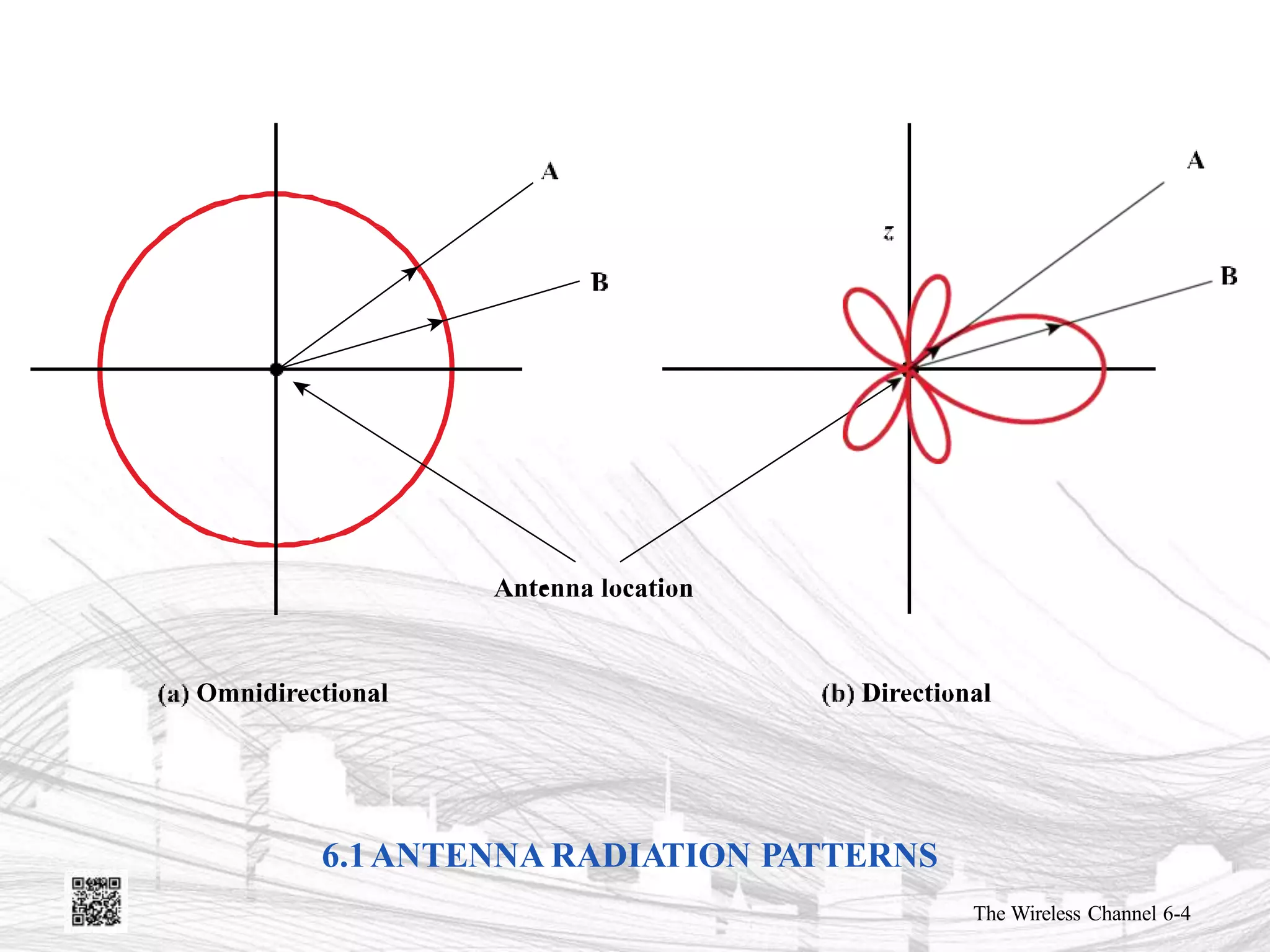
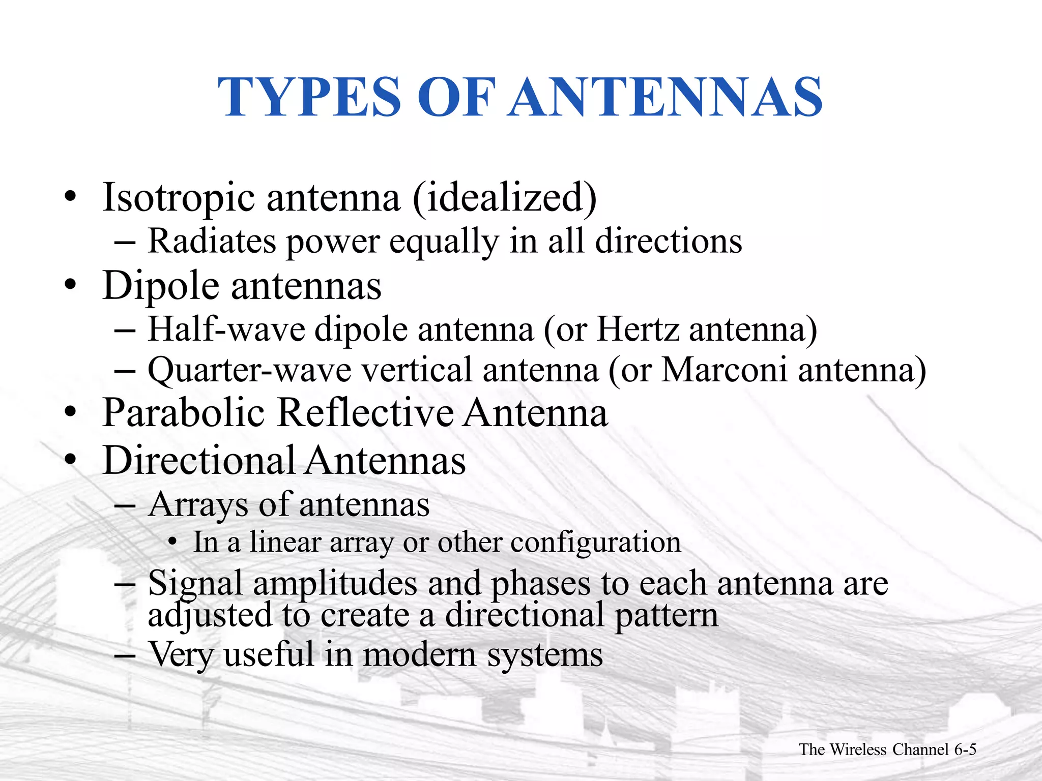
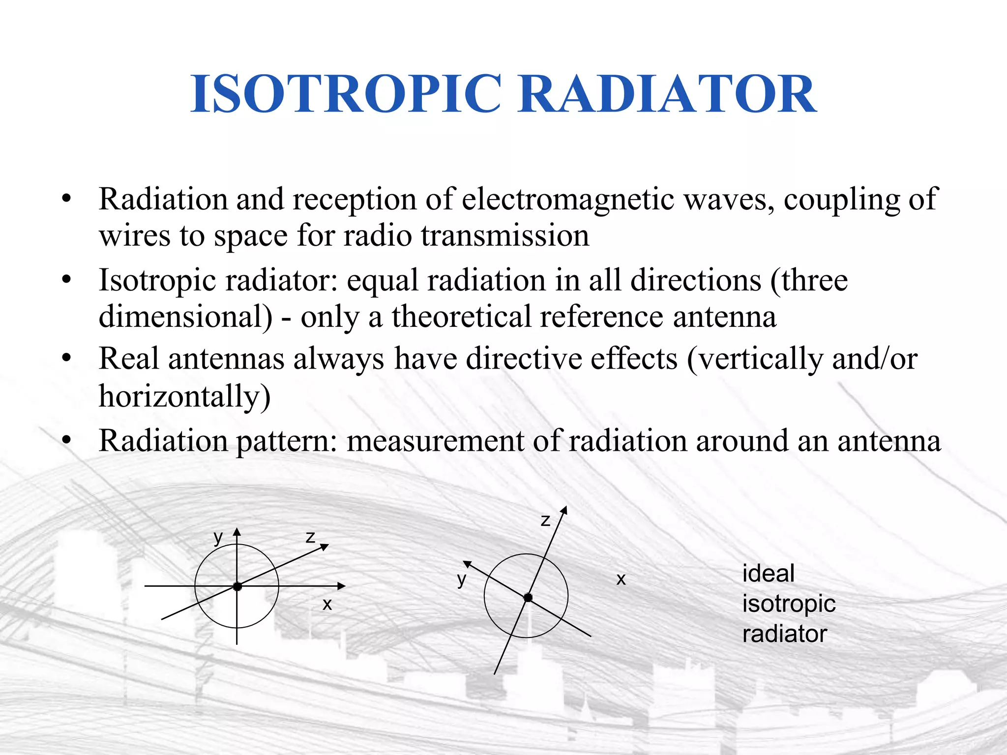
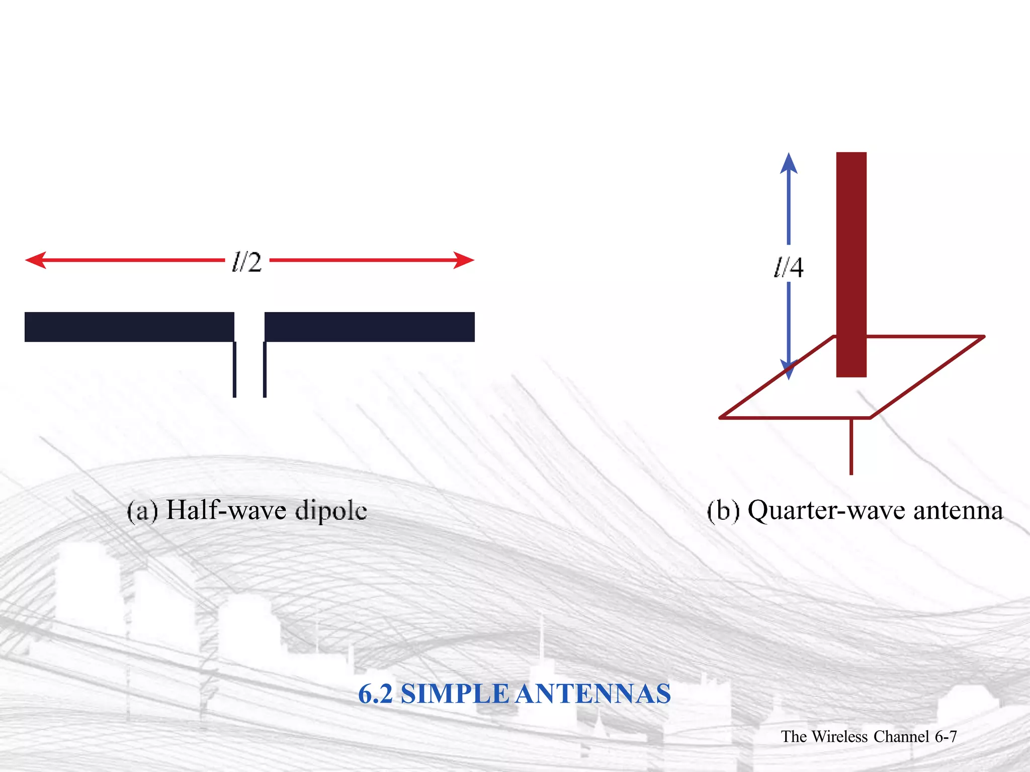
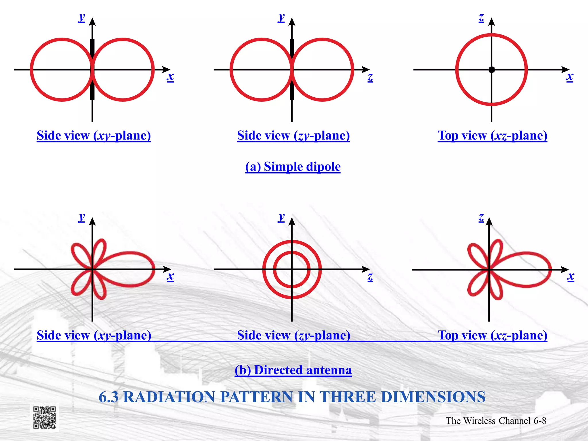
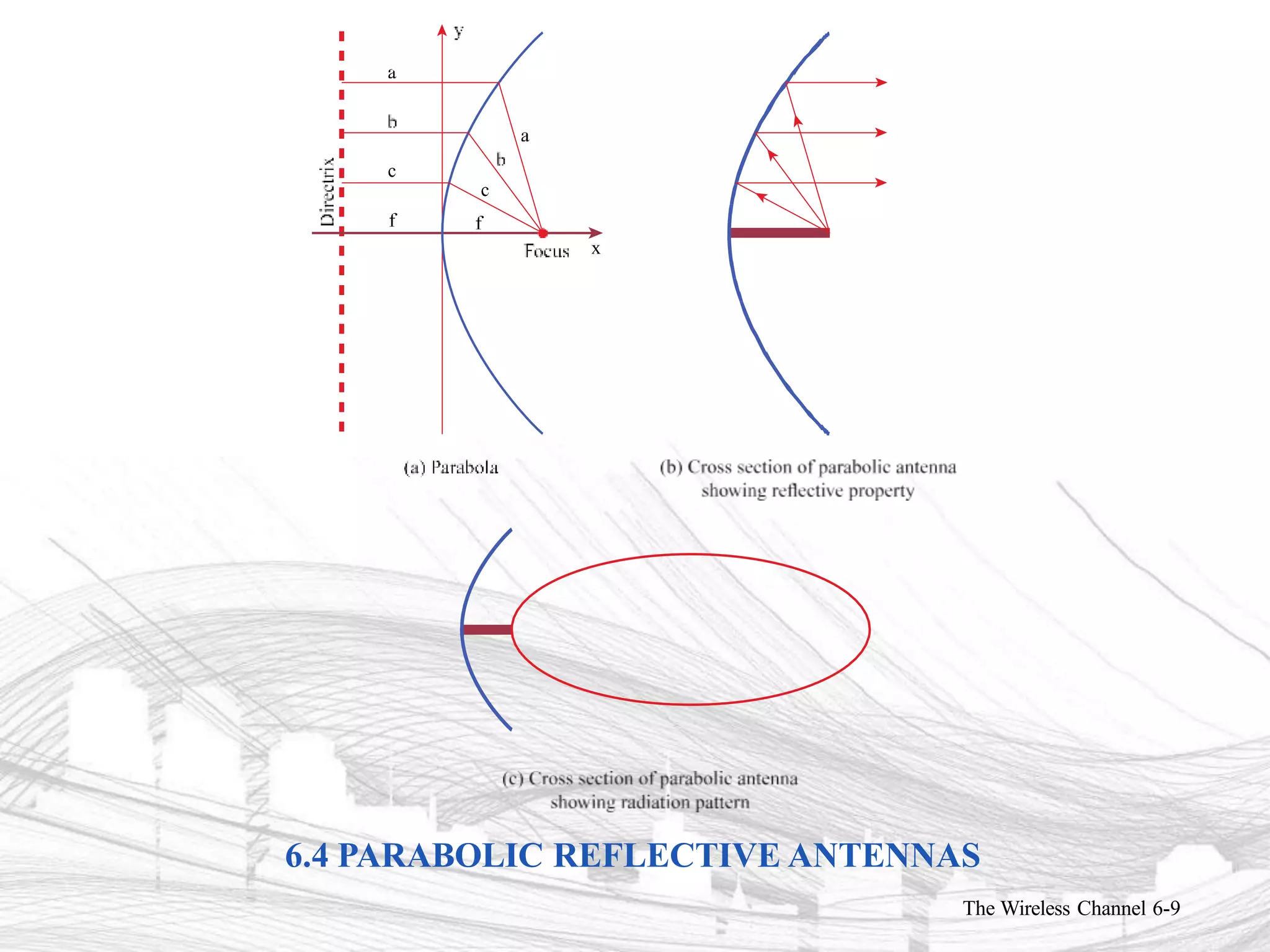
2) Key antenna types discussed are isotropic antennas, dipole antennas, parabolic reflective antennas, and directional antenna arrays.
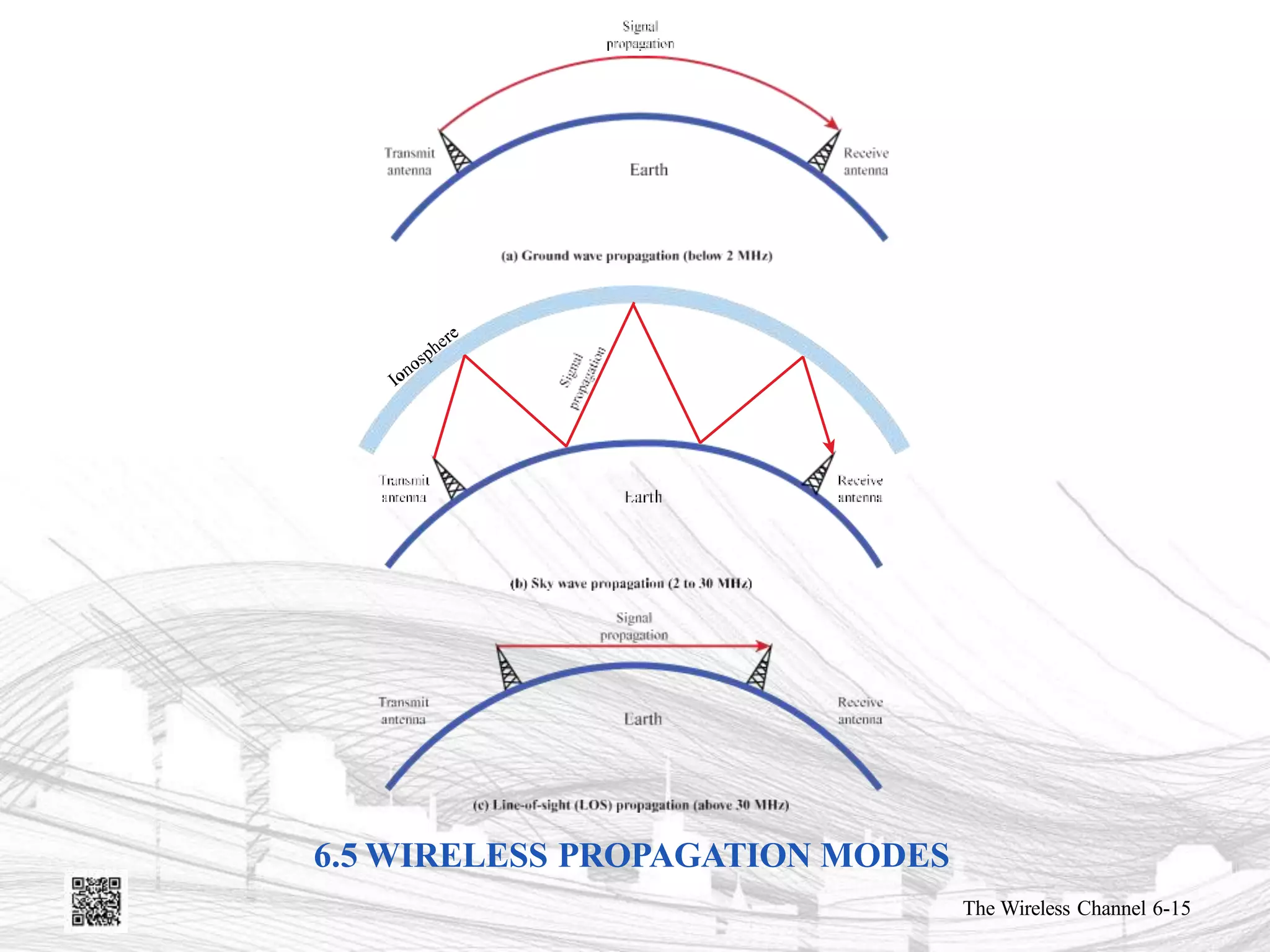
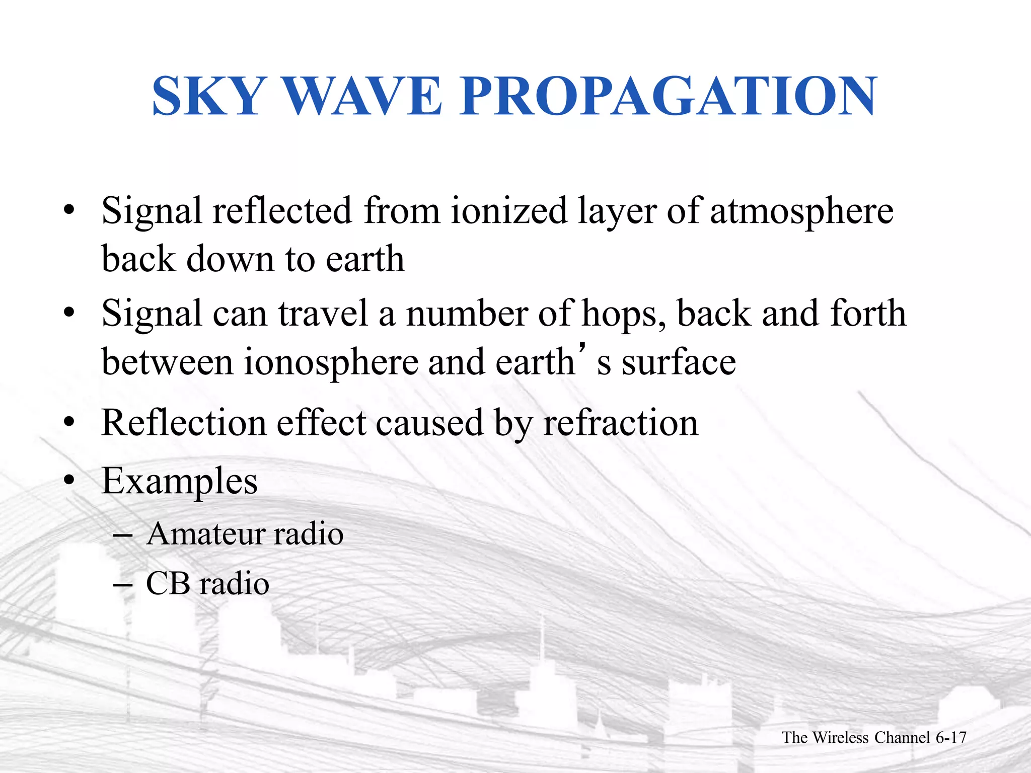
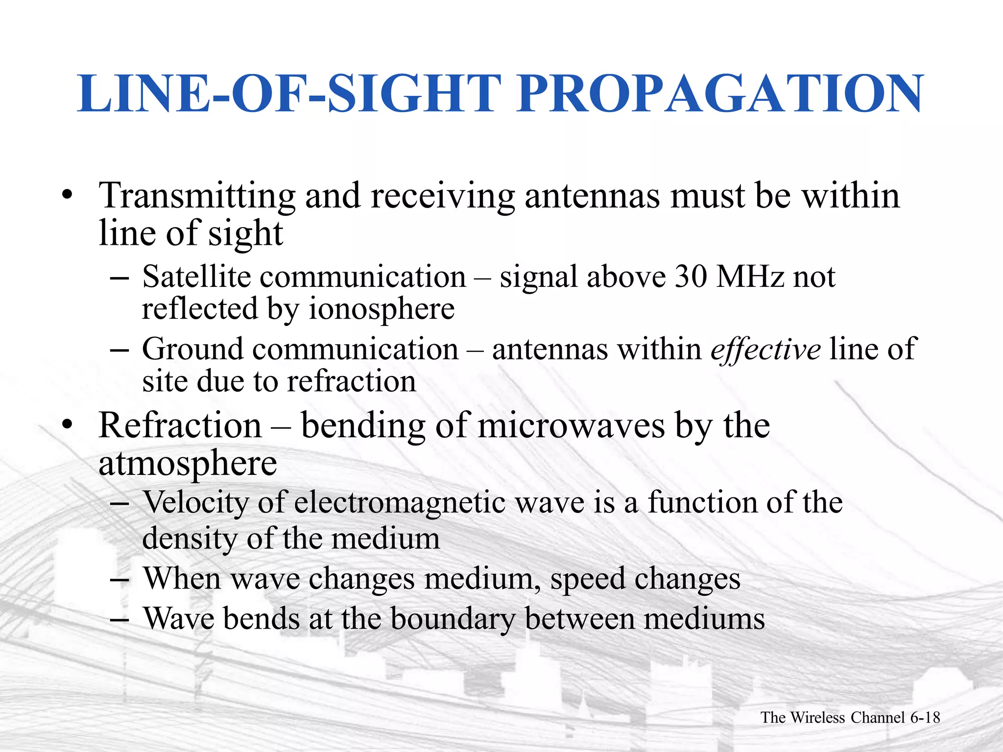
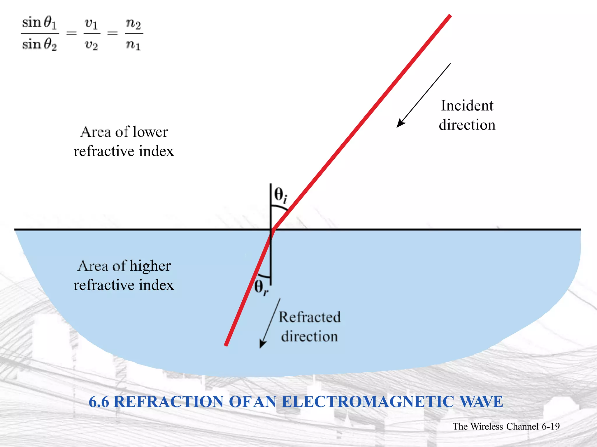
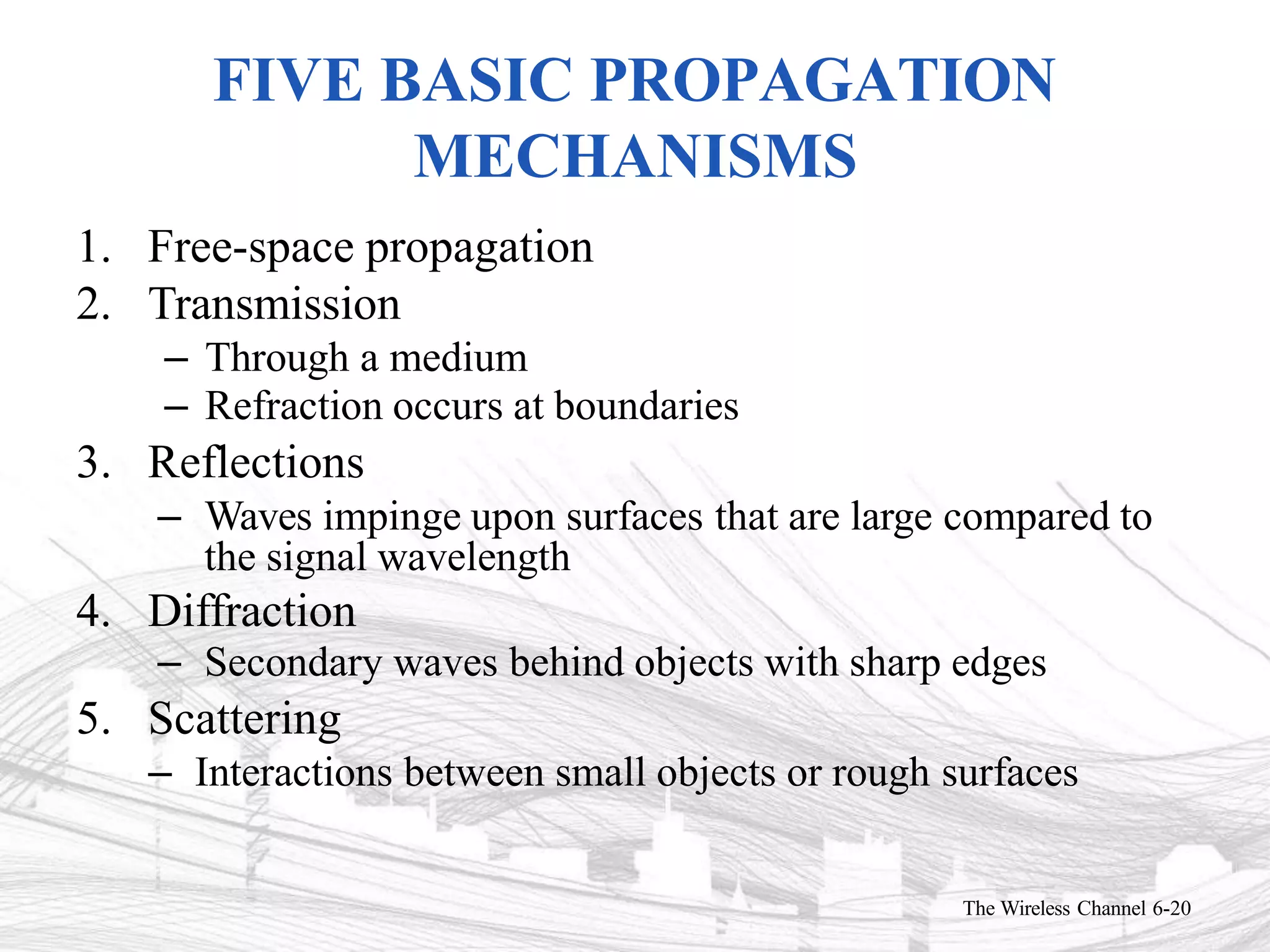
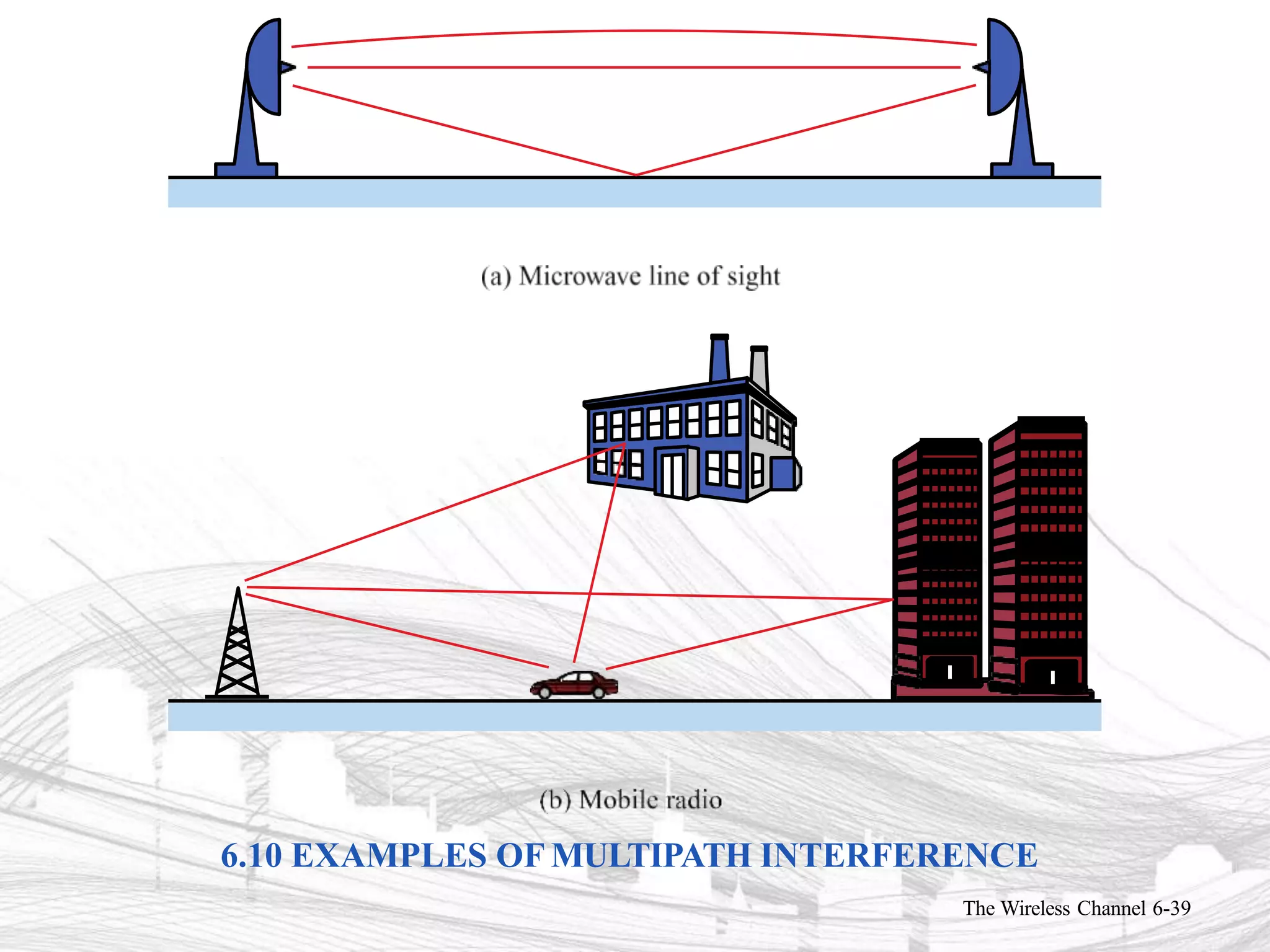
3) Propagation modes covered include ground-wave, sky-wave, and line-of-sight propagation.
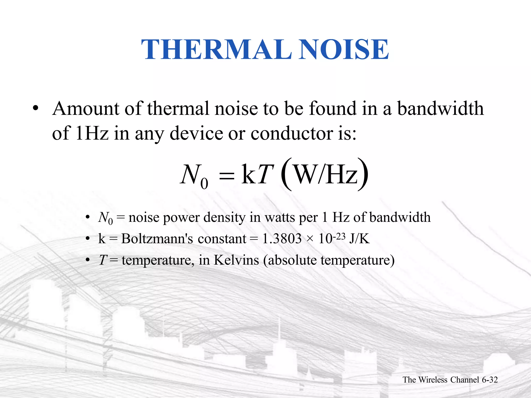
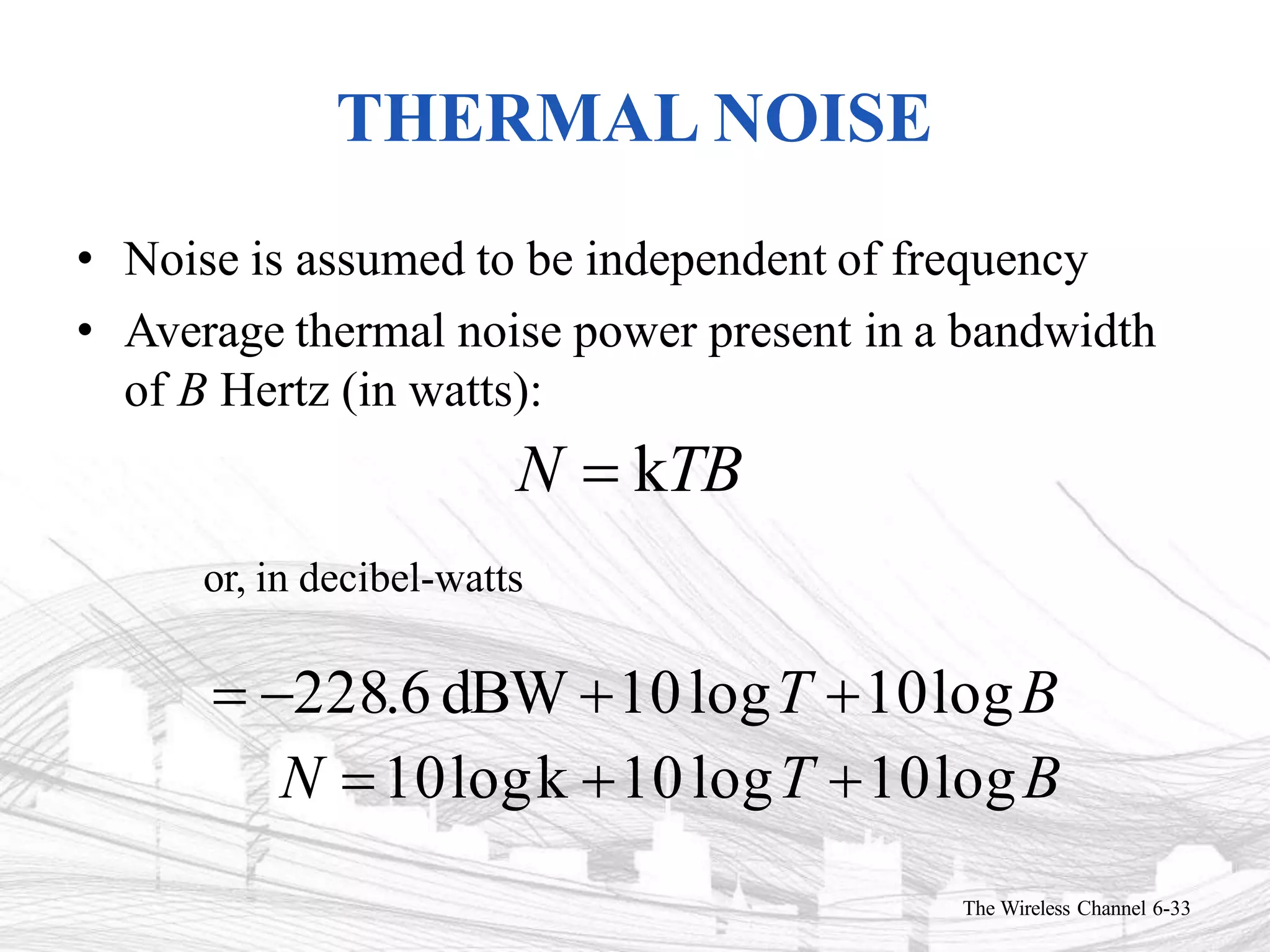
4) Sources of noise and interference addressed include thermal noise, intermodulation noise, crosstalk, and impulse noise.