SlideShare a Scribd company logo
NRI INSTITUTE OF TECHNOLOGY DEPARTMENT OF CIVIL ENGINEERING
1
B U I L D I N G M A T E R I A L S A N D C O N C R E T E T E C H N O L O G Y
UNIT IV {CO 3,5}
Hardened Concrete-Water / Cement ratio – Abram’s law, Gel space ratio, Nature of
strength of concrete – Maturity concept, Strength in tension and compression –
Properties of Hardened Concrete (Elasticity, Creep, Shrinkage, Poisson’s ratio, Water
absorption, Permeability, etc.), Relating between compression and tensile strength,
Curing
Unit-IV
S.No Long Answer Questions CO PO BTL Marks
1 What is water cement ratio and Abram’s law? 3,5 1,2,8 I 7
2
Evaluate the gel/space ratio and the theoretical
strength of a sample of concrete made with 400
gm. of cement with 0.4 water/cement ratio, on
full hydration and at 50 per cent hydration.
3,5 1,2,8 V 7
3 Define the gel/space ratio & water cement ratio 3,5 1,2,8 I 7
4
Evaluate the gel/space ratio and the theoretical
strength of a sample of concrete made with 500
gm. of cement with 0.5 water/cement ratio, on
full hydration and at 60 per cent hydration.
3,5 1,2,8 V 7
5 Elaborate the Properties of Hardened Concrete 3,5 1,2,8 VI 7
6
Explain Poisson’s ratio, Water absorption,
Permeability of Concrete 3,5 1,2,8 II,V 7
7 Explain Elasticity, Creep 3,5 1,2,8 II,V 7
8 Explain Maturity concept of concrete 3,5 1,2,8 II,V 7
9
Evaluate, the strength of a sample of fully
matured concrete is found to be 40.00 Mpa find
the strength of identical concrete at the age of 7
days when cured at an average temperature
during day time at 20°C, and night time at
10°C. The values of A is 32 and B is 54. 3,5 1,2,8 V 7
10
Explain Curing process and its importance in
strength gain to concrete 3,5 1,2,8 II,V 7
11
Explain different Curing process applied to
concrete 3,5 1,2,8 II,V 7
12
Explain how compression and tensile strength
of concrete are related to each other 3,5 1,2,8 II,V 7
13
Explain about Strength in tension and
compression of concrete 3,5 1,2,8 II,V 7
NRI INSTITUTE OF TECHNOLOGY DEPARTMENT OF CIVIL ENGINEERING
2
B U I L D I N G M A T E R I A L S A N D C O N C R E T E T E C H N O L O G Y
Water/Cement Ratio
Strength of concrete primarily depends upon the strength of cement paste. It
has been discussed that the strength of cement paste depends upon the dilution of
paste or in other words, the strength of paste increases with cement content and
decreases with air and water content.
In 1918 Duff Abrams presented his classic law in the form:
S =
where
x =water/cement ratio by volume and
For 28 days results the constants A and B are 14,000 lbs/sq. in. or 96.6 Mpa and 7
respectively.
1 Pounds per square inch (lbs/sq. in. ) = 0.0069 Megapascals
Abram’s water/cement ratio law states that the strength of concrete is only
dependent upon water/cement ratio provided the mix is workable. In the past many
theories have been propounded by many research workers. Some of them held valid
for some time and then underwent some changes while others did not stand the test
of time and hence slowly disappeared.
But Abrams’ water/cement ratio law stood the test of time and is held valid
even today as a fundamental truth in concrete-making practices. No doubt some
modifications have been suggested but the truth of the statement could not be
challenged.
Strictly speaking, it was Feret who formulated in as early as 1897, a general
rule defining the strength of the concrete paste and concrete in terms of volume
fractions of the constituents by the equation:
S = K
where S = Strength of concrete
c, e and a = volume of cement, water and air respectively and
K = a constant.
In this expression the volume of air is also included because it is not only the
water/ cement ratio but also the degree of compaction, which indirectly means the
volume of air-filled voids in the concrete is taken into account in estimating the
strength of concrete.
NRI INSTITUTE OF TECHNOLOGY DEPARTMENT OF CIVIL ENGINEERING
3
B U I L D I N G M A T E R I A L S A N D C O N C R E T E T E C H N O L O G Y
The relation between the water/cement ratio and strength of concrete is
shown in Fig. 7.1. It can be seen that lower water/cement ratio could be used when
the concrete is vibrated to achieve higher strength, whereas comparatively higher
water/cement ratio is required when concrete is hand compacted.
In both cases when the water/cement ratio is below the practical limit the
strength of the concrete falls rapidly due to introduction of air voids.
The graph showing the relationship between the strength and
water/cement ratio is approximately hyperbolic in shape.
Fig. Shows the relationship between compressive strength and
cement/water ratio.
Sometimes it is difficult to interpolate the intermediate value. From geometry
it can be deduced that if the graphs is drawn between the strength
and the cement/water ratio an approximately linear relationship will be obtained.
This linear relationship is more convenient to use than water/cement ratio curve
for interpolation.
Gel/Space Ratio
NRI INSTITUTE OF TECHNOLOGY DEPARTMENT OF CIVIL ENGINEERING
4
B U I L D I N G M A T E R I A L S A N D C O N C R E T E T E C H N O L O G Y
Many research workers commented on the validity of water/cement ratio law
as propounded by Duff Abrams. They have forwarded a few of the limitations of the
water/ cement ratio law and argued that “Abram’s water/cement ratio law can
only be called a rule and not a law because Abrams’ statement does not
include many qualifications necessary for
its validity to call it a law.”
Some of the limitations are
 That the strength at any water/cement ratio depends on the degree of hydration of
cement and its chemical and physical properties,
 The temperature at which the hydration takes place,
 The air content in case of air entrained concrete,
 The change in the effective water/cement ratio and
 The formation of fissures and cracks due to bleeding or shrinkage.
Instead of relating the strength to water/cement ratio, the strength can be more
correctly related to the solid products of hydration of cement to the space available
for formation of this product.
Powers and Brownyard have established the relationship between the
strength and Gel/space ratio.
This ratio is defined as the ratio of the volume of the hydrated cement
paste to the sum of volumes of the hydrated cement and of the capillary pores.
Power’s experiment showed that the strength of concrete bears a specific
relationship with the gel/space ratio. He found the relationship to be S = 240
x3
Where x is the gel/space ratio and
240 represents the intrinsic strength of the gel in MPa for the type of cement and
specimen used.
The strength calculated by Power’s expression holds good for an ideal case. It
is pointed out that the relationship between the strength and water/cement ratio
will hold good primarily for 28 days strength for fully compacted concrete, whereas,
the relationship between the strength and gel/space ratio is independent of age.
Gel/space ratio can be calculated at any age and for any fraction of hydration
of cement. The following examples show how to calculate the gel/space ratio.
NRI INSTITUTE OF TECHNOLOGY DEPARTMENT OF CIVIL ENGINEERING
5
B U I L D I N G M A T E R I A L S A N D C O N C R E T E T E C H N O L O G Y
Fig. Shows the relationship between strength and gel/space ratio.
Calculation of gel/space ratio for complete hydration
Let C = weight of cement in gm.
VC = specific volume of cement = 0.319 ml/gm.
WO = volume of mixing water in ml.
Assuming that 1 ml. of cement on hydration will produce 2.06 ml of gel,
Volume of gel = C x 0.319 x 2.06 = 0.657 C
Space available = C x 0.319 + WO
∴ Gel/Space ratio = x =
𝑽𝒐𝒍𝒖𝒎𝒆 𝒐𝒇 𝑮𝒆𝒍
𝑺𝒑𝒂𝒄𝒆 𝑨𝒗𝒂𝒊𝒍𝒂𝒃𝒍𝒆
∴ Gel/Space ratio = x =
𝟎.𝟔𝟓𝟕 𝑪
𝟎.𝟑𝟏𝟗 𝑪 𝑾𝟎
Calculation of gel/space ratio for partial hydration
Let α = Fraction of cement that has hydrated
Volume of gel = C x α x 0.319 x 2.06 = 0.657C α
Total space available = C VC α + WO
∴ Gel/Space ratio = x =
𝑽𝒐𝒍𝒖𝒎𝒆 𝒐𝒇 𝑮𝒆𝒍
𝑺𝒑𝒂𝒄𝒆 𝑨𝒗𝒂𝒊𝒍𝒂𝒃𝒍𝒆
∴ Gel/Space ratio = x =
𝟎.𝟔𝟓𝟕 𝑪𝜶
𝟎.𝟑𝟏𝟗 𝑪𝜶 𝑾𝟎
Example: 1
NRI INSTITUTE OF TECHNOLOGY DEPARTMENT OF CIVIL ENGINEERING
6
B U I L D I N G M A T E R I A L S A N D C O N C R E T E T E C H N O L O G Y
Calculate the gel/space ratio and the theoretical strength of a sample of
concrete made with 500 gm. of cement with 0.5 water/cement ratio, on full
hydration and at 60 per cent hydration.
Gel/space ratio on full hydration = x =
𝑽𝒐𝒍𝒖𝒎𝒆 𝒐𝒇 𝑮𝒆𝒍
𝑺𝒑𝒂𝒄𝒆 𝑨𝒗𝒂𝒊𝒍𝒂𝒃𝒍𝒆
Gel/Space ratio on full hydration = x =
𝟎.𝟔𝟓𝟕 𝑪
𝟎.𝟑𝟏𝟗 𝑪 𝑾𝟎
Given 500 gm. of cement with 0.5 water/cement ratio
Gel/Space ratio on full hydration = x =
𝟎.𝟔𝟓𝟕∗𝟓𝟎𝟎
𝟎.𝟑𝟏𝟗∗𝟓𝟎𝟎 (𝟎.𝟓∗𝟓𝟎𝟎)
x = 0.802 say 0.8
Theoretical strength of concrete = S = 240 x3
= 240 x (0.8)3
∴ Theoretical strength of concrete on full hydration = S = 123 Mpa
Gel/space ratio for 60 percent hydration.
Let α = Fraction of cement that has hydrated = 60 % = 60/100 = 0.6
Volume of gel = C x α x 0.319 x 2.06 = 0.657C α
Total space available = C VC α + WO
Gel/Space ratio = x =
𝑽𝒐𝒍𝒖𝒎𝒆 𝒐𝒇 𝑮𝒆𝒍
𝑺𝒑𝒂𝒄𝒆 𝑨𝒗𝒂𝒊𝒍𝒂𝒃𝒍𝒆
Gel/Space ratio for 60 percent hydration = x =
𝟎.𝟔𝟓𝟕 𝑪𝜶
𝟎.𝟑𝟏𝟗 𝑪𝜶 𝑾𝟎
=
𝟎.𝟔𝟓𝟕∗𝟓𝟎𝟎∗𝟎.𝟔
(𝟎.𝟑𝟏𝟗∗𝟓𝟎𝟎∗𝟎.𝟔) (𝟓𝟎𝟎∗𝟎.𝟓)
Gel/Space ratio for 60 percent hydration = x = 0.57
Theoretical strength of concrete at 60 per cent hydration = S = 240 x3
=240 x (0.57)3
∴ Theoretical strength of concrete at 60 per cent hydration = 44.4 MPa
Example: 2
NRI INSTITUTE OF TECHNOLOGY DEPARTMENT OF CIVIL ENGINEERING
7
B U I L D I N G M A T E R I A L S A N D C O N C R E T E T E C H N O L O G Y
Calculate the gel/space ratio and the theoretical strength of a sample of
concrete made with 450 gm. of cement with 0.45 water/cement ratio, on full
hydration and at 55 per cent hydration.
a) Gel/space ratio on full hydration
Volume of gel = C x 0.319 x 2.06 = 0.657C
Total space available = C VC + WO
Gel/space ratio on full hydration = x =
𝑽𝒐𝒍𝒖𝒎𝒆 𝒐𝒇 𝑮𝒆𝒍
𝑺𝒑𝒂𝒄𝒆 𝑨𝒗𝒂𝒊𝒍𝒂𝒃𝒍𝒆
Gel/Space ratio on full hydration = x =
𝟎.𝟔𝟓𝟕 𝑪
𝟎.𝟑𝟏𝟗 𝑪 𝑾𝟎
Given 450 gm. of cement with 0.45 water/cement ratio
Gel/Space ratio on full hydration = x =
𝟎.𝟔𝟓𝟕∗𝟒𝟓𝟎
𝟎.𝟑𝟏𝟗∗𝟒𝟓𝟎 (𝟎.𝟒𝟓∗𝟒𝟓𝟎)
x = 0.854 say 0.85
Theoretical strength of concrete = S = 240 x3
= 240 x (0.85)3
∴ Theoretical strength of concrete on full hydration = S = 149.66 Mpa
b) Gel/space ratio for 55 percent hydration.
Let α = Fraction of cement that has hydrated = 55 % = 55/100 = 0.55
Volume of gel = C x α x 0.319 x 2.06 = 0.657C α
Total space available = C VC α + WO
Gel/Space ratio = x =
𝑽𝒐𝒍𝒖𝒎𝒆 𝒐𝒇 𝑮𝒆𝒍
𝑺𝒑𝒂𝒄𝒆 𝑨𝒗𝒂𝒊𝒍𝒂𝒃𝒍𝒆
Gel/Space ratio for 60 percent hydration = x =
𝟎.𝟔𝟓𝟕 𝑪𝜶
𝟎.𝟑𝟏𝟗 𝑪𝜶 𝑾𝟎
=
𝟎.𝟔𝟓𝟕∗𝟒𝟓𝟎∗𝟎.𝟓𝟓
(𝟎.𝟑𝟏𝟗∗𝟒𝟓𝟎∗𝟎.𝟓𝟓) (𝟒𝟓𝟎∗𝟎.𝟒𝟓)
Gel/Space ratio for 60 percent hydration = x = 0.577
Theoretical strength of concrete at 60 per cent hydration = S = 240 x3
=240 x (0.577)3
∴ Theoretical strength of concrete at 60 per cent hydration = 46.28 MPa
Example: 3
NRI INSTITUTE OF TECHNOLOGY DEPARTMENT OF CIVIL ENGINEERING
8
B U I L D I N G M A T E R I A L S A N D C O N C R E T E T E C H N O L O G Y
Calculate the gel/space ratio and the theoretical strength of a sample of
concrete made with 550 gm. of cement with cement/water ratio as 2, on full
hydration and at 70 per cent hydration.
a) Gel/space ratio on full hydration
Volume of gel = C x 0.319 x 2.06 = 0.657C
Total space available = C VC + WO
Gel/space ratio on full hydration = x =
𝑽𝒐𝒍𝒖𝒎𝒆 𝒐𝒇 𝑮𝒆𝒍
𝑺𝒑𝒂𝒄𝒆 𝑨𝒗𝒂𝒊𝒍𝒂𝒃𝒍𝒆
Gel/Space ratio on full hydration = x =
𝟎.𝟔𝟓𝟕 𝑪
𝟎.𝟑𝟏𝟗 𝑪 𝑾𝟎
Given 550 gm. of cement with cement/water ratio as 2
cement/water = 2
water (𝑾𝟎) = cement/ 2 = 550/2 = 275
Gel/Space ratio on full hydration = x =
𝟎.𝟔𝟓𝟕∗𝟓𝟓𝟎
𝟎.𝟑𝟏𝟗∗𝟓𝟓𝟎 𝟐𝟕𝟓
x = 0.80
Theoretical strength of concrete = S = 240 x3
= 240 x (0.80)3
∴ Theoretical strength of concrete on full hydration = S = 124 Mpa
b) Gel/space ratio for 70 percent hydration.
Let α = Fraction of cement that has hydrated = 70 % = 70/100 = 0.70
Volume of gel = C x α x 0.319 x 2.06 = 0.657C α
Total space available = C VC α + WO
Gel/Space ratio = x =
𝑽𝒐𝒍𝒖𝒎𝒆 𝒐𝒇 𝑮𝒆𝒍
𝑺𝒑𝒂𝒄𝒆 𝑨𝒗𝒂𝒊𝒍𝒂𝒃𝒍𝒆
Gel/Space ratio for 60 percent hydration = x =
𝟎.𝟔𝟓𝟕 𝑪𝜶
𝟎.𝟑𝟏𝟗 𝑪𝜶 𝑾𝟎
=
𝟎.𝟔𝟓𝟕∗𝟓𝟓𝟎∗𝟎.𝟕
(𝟎.𝟑𝟏𝟗∗𝟓𝟓𝟎∗𝟎.𝟕) (𝟐𝟕𝟓)
Gel/Space ratio for 60 percent hydration = x = 0.6358
Theoretical strength of concrete at 60 per cent hydration = S = 240 x3
=240 x (0.6358)3
∴ Theoretical strength of concrete at 60 per cent hydration = 61.7 MPa
NRI INSTITUTE OF TECHNOLOGY DEPARTMENT OF CIVIL ENGINEERING
9
B U I L D I N G M A T E R I A L S A N D C O N C R E T E T E C H N O L O G Y
There is a lot of difference between the theoretical strength of concrete and
actual strength of concrete. Actual strength of concrete is much lower than the
theoretical strength estimated on the basis of molecular cohesion and surface energy
of a solid assumed to be perfectly homogeneous and flawless.
The actual reduction of strength is due to the presence of flaws.
Griffith postulated his theory on the flaws in concrete.
He explains that the flaws in concrete lead to a high stress concentration in
the material under load, so that a very high stress is reached in and around the
flaws with the result that the material gets fractured around this flaw while the
average stress on the material, taking the cross section of the material as a whole,
remains comparatively low.
The flaws vary in size. The high stress concentration takes place around a few
of the larger flaws. This situation leads to failure of the material at a much lower
stress intensity considering the whole process. Presence of bigger flaws brings down
the actual strength to a much lower value than the theoretical strength.
Cement paste in concrete contains many discontinuities such as voids,
fissures, bleeding channels, rupture of bond due to drying shrinkage and
temperature stresses etc. It has been difficult to explain how exactly these various
flaws contribute to the reduction in actual strength of concrete.
However, Griffith’s theory which explains the failure of concrete has been
accepted to satisfactorily explain the failure of brittle materials such as concrete.
Maturity Concept of Concrete
While dealing with curing and strength development, we have so far
considered only the time aspect. It has been pointed out earlier that it is not only
the time but also the temperature during the early period of hydration that influence
the rate of gain of strength of concrete.
Since the strength development of concrete depends on both time and
temperature it can be said that strength is a function of summation of product of
time and temperature. This summation is called maturity of concrete.
Maturity = Σ (time x temperature)
NRI INSTITUTE OF TECHNOLOGY DEPARTMENT OF CIVIL ENGINEERING
10
B U I L D I N G M A T E R I A L S A N D C O N C R E T E T E C H N O L O G Y
The temperature is reckoned from an origin lying between –12 and –10°C. It
was experimentally found that the hydration of concrete continues to take place up
to about –11°C. Therefore, –11°C is taken as a datum line for computing maturity.
Maturity is measured in degree centigrade hours (°C hrs) or degree centigrade
days (°C days). Fig. 7.6. shows that the strength plotted against the logarithm of
maturity gives a straight line.
A sample of concrete cured at 18°C for 28 days is taken as fully matured
concrete. Its maturity would be equal to
Maturity of concrete at the age of 28 days
= Σ (time x Temperature)
28 x 24 x [18 – (–11)] = 19488°C h.
However, in standard calculations the maturity of fully cured concrete is taken
as 19,800°Ch. (The discrepancy is because of the origin or the datum is not exactly
being –11 0C as used in calculation).
If the period is broken into smaller intervals and if the corresponding
temperature is recorded for each interval of time, the summation of the product of
time and temperature will give an accurate picture of the maturity of concrete.
In the absence of such detailed temperature history with respect to the time
interval, the maturity figure can be arrived at by multiplying duration in hours by
NRI INSTITUTE OF TECHNOLOGY DEPARTMENT OF CIVIL ENGINEERING
11
B U I L D I N G M A T E R I A L S A N D C O N C R E T E T E C H N O L O G Y
the average temperature at which the concrete is cured. Of course, the maturity
calculated as above will be less accurate.
Maturity concept is useful for estimating the strength of concrete at any
other maturity as a percentage of strength of concrete of known maturity.
In other words, if we know the strength of concrete at full maturity
(19,800°Ch), we can calculate the percentage strength of identical concrete at any
other maturity by using the following equation given by Plowman.
Strength at any maturity as a percentage of strength at maturity of
19,800°Ch= A + B log10 {(maturity) / 1000}
The values of coefficients, A and B depend on the strength level of concrete.
The values are given in Table 7.5
The values of A and B are plotted against the cube strength at the maturity of
19,800° Ch. A straight line relationship will be obtained indicating that they are
directly proportional to the strength. Plowman divided the strength into 4 zones as
shown in Table 7.5 and has assigned the values of A and B for each zone.
It is to be noted that the maturity equation holds good for the initial
temperature of concrete less than about 38°C. Fig. 7.7 gives the value of constant A
and B when strength and temperature are expressed in lbs./squinch and °F
respectively.
NRI INSTITUTE OF TECHNOLOGY DEPARTMENT OF CIVIL ENGINEERING
12
B U I L D I N G M A T E R I A L S A N D C O N C R E T E T E C H N O L O G Y
Fig. 7.7 value of constant A and B when strength and temperature are
expressed in lbs./squinch and °F respectively.
The following examples illustrate the theory.
Example 1:
The strength of a sample of fully matured concrete is found to be 40.00
Mpa find the strength of identical concrete at the age of 7 days when cured
at an average temperature during day time at 20°C, and night time at 10°C.
Maturity of concrete at the age of 7 days
= Σ (time x Temperature)
M(t) = Σ (Ta – T0)* Δt
= 7 x 12 x [20 – (–11)] + 7 x 12 x [10 – (– 11)]
= 7 x 12 x 31 + 7 x 12 x 21
= 4368°Ch.
The strength range of this concrete falls in Zone III for which the constant A is 32
and B is 54.
∴ The percentage strength of concrete at maturity of
4368°Ch. = A + B log 10 {(4368) /1000}
= 32 + 54 x log10 (4.368)
= 32 + 54 x 0.6403
NRI INSTITUTE OF TECHNOLOGY DEPARTMENT OF CIVIL ENGINEERING
13
B U I L D I N G M A T E R I A L S A N D C O N C R E T E T E C H N O L O G Y
= 66.5 Mpa
Maturity concept is useful for estimating the strength of concrete at any
other maturity as a percentage of strength of concrete of known maturity.
∴ The strength at 7 days = 40.0 x (66.5/100)
= 26.5 Mpa
Example: 2
Evaluate, the strength of a sample of fully matured concrete is found to be
50.00 Mpa find the strength of identical concrete at the age of 8 days when cured at
an average temperature during day time at 25°C, and night time at 11°C. The values
of A is 32 and B is 54
Maturity of concrete at the age of 8 days
= Σ (time x Temperature)
M(t) = Σ (Ta – T0) * Δt
= 7 x 12 x [25 – (–11)] + 7 x 12 x [11 – (– 11)]
= (7 x 12 x 36) + (7 x 12 x 22)
= 4872 °Ch.
Given , sample of fully matured concrete is found to be 50.00 Mpa
The strength range of this concrete falls in Zone III for which the constant A is 32
and B is 54.
∴ The percentage strength of concrete at maturity of
NRI INSTITUTE OF TECHNOLOGY DEPARTMENT OF CIVIL ENGINEERING
14
B U I L D I N G M A T E R I A L S A N D C O N C R E T E T E C H N O L O G Y
4872°Ch. = A + B log 10 {(4368) /1000}
= 32 + 54 x log10 (4.872)
= 32 + 54 x 0.687
= 69.13 Mpa
Maturity concept is useful for estimating the strength of concrete at any
other maturity as a percentage of strength of concrete of known maturity.
∴ The strength at 8 days = 50.0 x (69.13/100)
= 34.56 Mpa
Strength in tension and compression
Concrete has been used for construction since Roman times. It is essentially artificial
rock, made with a paste of cement and water to bind together some solid material like sand or
gravel. Modern concrete is made with Portland cement, water, sand and some rock called
aggregate. It is a versatile and durable building material, used in roadways, bridges, houses,
commercial buildings and many other places. Properly installed and cured, it will last for years.
Compression
Concrete has enormous compressive strength, the ability to withstand heavy weights or
forces on it. It also gains strength as it ages. Concrete will solidify in a few hours and harden or
set in a few days, but continues to gain strength for at least 28 days. Some very thick concrete
structures, like dams, will continue to gain strength for months or years.
NRI INSTITUTE OF TECHNOLOGY DEPARTMENT OF CIVIL ENGINEERING
15
B U I L D I N G M A T E R I A L S A N D C O N C R E T E T E C H N O L O G Y
Tension
Concrete has almost no tensile strength, the ability to withstand pressing or stretching.
Put a board between two supports and press down on the center. It will bend. The top of the
board is under compression, the bottom which bends is under tension.
Concrete can resist the compression, but will break under the tension. Concrete cracks
in roads and slabs are largely due to tension; different weights in different areas produce tensile
forces.
Tension-Compression Ratio
The tension to compression ratio for concrete is about 10 to 15 percent. That is, it can
withstand about 10 times the pushing force or compression of the pulling force or tension. Both
strengths increase with age, but the ratio is steady.
Portland cement concrete less than a year old has compression strength of 1,000 pounds
per square inch (psi) and tension strength of 200 psi. Concrete more than a year old has
compression psi of 2,000 pounds and tension psi of 400.
Reinforcing
To give concrete tensile strength -- to support beams in a bridge or building, for instance
-- reinforcing steel is added.
NRI INSTITUTE OF TECHNOLOGY DEPARTMENT OF CIVIL ENGINEERING
16
B U I L D I N G M A T E R I A L S A N D C O N C R E T E T E C H N O L O G Y
Steel has great tensile strength; it bends without breaking. The combination produces
the strength needed for bridge girders, roadways, building walls and other construction.
An even stronger combination is prestressed concrete. The reinforcing steel is stretched
or put under tension before concrete is poured around it. When tension is released, the tendency
of the steel to return to its unstretched form adds reverse tension which strengthens a concrete
beam or girder.
Relation Between Compressive and Tensile Strength
In reinforced concrete construction the strength of the concrete in
compression is only taken into consideration. The tensile strength of concrete is
generally not taken into consideration. But the design of concrete pavement slabs is
often based on the flexural strength of concrete.
NRI INSTITUTE OF TECHNOLOGY DEPARTMENT OF CIVIL ENGINEERING
17
B U I L D I N G M A T E R I A L S A N D C O N C R E T E T E C H N O L O G Y
Therefore, it is necessary to assess the flexural strength of concrete either from
the compressive strength or independently.
As measurements and control of compressive strength in field are easier and
more convenient, it has been customary to find out the compressive strength for
different conditions and to correlate this compressive strength to flexural strength.
Having established a satisfactory relationship between flexural and
compressive strength, pavement, can be designed for a specified flexural strength
value, or this value could be used in any other situations when required.
It is seen that strength of concrete in compression and tension (both direct tension
and flexural tension) are closely related, but the relationship is not of the type of
direct proportionality. The ratio of the two strengths depends on general level of
strength of concrete.
In other words, for higher compressive strength concrete shows higher tensile
strength, but the rate of increase of tensile strength is of decreasing order.
The type of coarse aggregate influences this relationship. Crushed aggregate
gives relatively higher flexural strength than compressive strength. This is attributed
to the improved bond strength between cement paste and aggregate particles.
NRI INSTITUTE OF TECHNOLOGY DEPARTMENT OF CIVIL ENGINEERING
18
B U I L D I N G M A T E R I A L S A N D C O N C R E T E T E C H N O L O G Y
The tensile strength of concrete, as compared to its compressive strength, is
more sensitive to improper curing. This may be due to the inferior quality of gel
formation as a result of improper curing and also due to the fact that improperly
cured concrete may suffer from more shrinkage cracks.
“The use of pozzolanic material increases the tensile strength of concrete.”
From the extensive study, carried out at Central Road Research Laboratory
(CRRI) the following statistical relationship between tensile strength and
compressive strength were established.
(i) y = 15.3x – 9.00 for 20 mm maximum size aggregate.
(ii) y = 14.1x – 10.4 for 20 mm maximum size natural gravel.
(iii) y = 9.9x – 0.55 for 40 mm maximum size crushed aggregate.
(iv) y = 9.8x – 2.52 for 40 mm maximum size natural gravel.
Where y is the compressive strength of concrete MPa and
x is the flexural strength of concrete MPa.
Subjecting all the data to statistical treatment the following general
relationship has been established at CRRI between flexural and compressive
strength of concrete:
y = 11x – 3.4
The flexural to compressive strength ratio was higher with aggregate of 40 mm
maximum size than with those of 20 mm maximum size.
In general, the ratio was found to be slightly higher in the case of natural
gravel as compared to crushed stone.
NRI INSTITUTE OF TECHNOLOGY DEPARTMENT OF CIVIL ENGINEERING
19
B U I L D I N G M A T E R I A L S A N D C O N C R E T E T E C H N O L O G Y
Fig. shows the relationships between compressive strength and flexural
strength of concrete for various aggregates.
The flexural strength of concrete was found to be 8 to 11 per cent of the
compressive strength of the concrete for higher ranges of concrete strength
(greater than 25 MPa) and 9 to 12.8 per cent for lower ranges of concrete
strength (less than 25 MPa) as shown in Table 7.6.
Flexural strength of concrete is usually found by testing plain concrete beams.
Two methods of loading of the beam specimen for finding out flexural strength are
practiced:
Central point loading and third points loading
Experience shows that the variability of results is less in third-point loading.
The results of the flexural strength tested under central and third-points loading
with constant span to depth ratios of 4 were analyzed statistically and the following
general relationship was obtained at Central Road Research Laboratory.
x1 = x2 + 0.72
where, x1 = flexural strength (MPa) of concrete under central point loading and
x2 = flexural strength (MPa) of concrete under third point loading.
In all the cases the central loading gave higher average value than the third-
point loading irrespective of the size of the sample. The higher strength obtained in
the case of central loading may be attributed to the fact that the beam is being
subjected to the maximum stress at a pre-determined location not necessarily the
weakest.
NRI INSTITUTE OF TECHNOLOGY DEPARTMENT OF CIVIL ENGINEERING
20
B U I L D I N G M A T E R I A L S A N D C O N C R E T E T E C H N O L O G Y
In the standard methods for finding the flexural strength of concrete,
the span to depth ratio of the specimen is kept at 4.
If the span to depth ratio is increased or decreased, the flexural strength was
found to alter. A change in this ratio by one induced 3 per cent and 2.5 per cent
change in strength when tested by third-point and central point loading respectively.
With the increase in span to depth ratio the flexural strength
decreased.
The rate of stress application was found to influence the flexural strength of
concrete to a very significant extent. The strength increased up to about 25 per cent
with increase in stressing rate compared to the standard rate of 0.7 MPa per minute.
The increase was found more with the leaner mixes.
There are number of empirical relationships connecting tensile strength and
compressive strength of concrete. One of the common relationships is shown below.
where, value of K varies from 6.2 for gravels to
K varies from 10.4 for crushed rock
(average value of K is 8.3) and
value of n may vary from 1/2 to 3/4
Further data obtained at the Laboratories of Portland Cement Association
giving the relationship between compressive and tensile strength of concrete is
shown in Table 7.7.
The Indian Standard IS 456 of 2000 gives the following relationship between the
compressive strength and flexural strength
where fck is the characteristic compressive strength of concrete @ 28 days in
N/mm2
NRI INSTITUTE OF TECHNOLOGY DEPARTMENT OF CIVIL ENGINEERING
21
B U I L D I N G M A T E R I A L S A N D C O N C R E T E T E C H N O L O G Y
Testing of hardened concrete plays an important role in controlling and
confirming the quality of cement concrete works. Systematic testing of raw
materials, fresh concrete and hardened concrete are inseparable part of any quality
control program for concrete, which helps to achieve higher efficiency of the material
used and greater assurance of the performance of the concrete with regard to both
strength and durability. The test methods should be simple, direct and convenient
to apply.
One of the purposes of testing hardened concrete is to confirm that the
concrete used at site has developed the required strength. As the hardening of the
concrete takes time, one will not come to know, the actual strength of concrete for
some time. This is an inherent disadvantage in conventional test.
But, if strength of concrete is to be known at an early period, accelerated
strength test can be carried out to predict 28 days strength. But mostly when correct
materials are used and careful steps are taken at every stage of the work, concretes
normally give the required strength. The tests also have a deterring effect on those
responsible for construction work.
The results of the test on hardened concrete, even if they are known late, helps
to reveal the quality of concrete and enable adjustments to be made in the
production of further concretes. Tests are made by casting cubes or cylinder from
the representative concrete or cores cut from the actual concrete.
It is to be remembered that standard compression test specimens give a
measure of the potential strength of the concrete, and not of the strength of the
concrete in structure. Knowledge of the strength of concrete in structure cannot be
directly obtained from tests on separately made specimens.
NRI INSTITUTE OF TECHNOLOGY DEPARTMENT OF CIVIL ENGINEERING
22
B U I L D I N G M A T E R I A L S A N D C O N C R E T E T E C H N O L O G Y
Properties of Hardened Concrete
Permeability:
Hardened Concrete has a tendency to become porous due to the presence of
voids formed during or after placing of concrete.
Penetration by the substance may adversely affect the durability, i.e. Ca(OH)2
leach out and corrosion occurs due to lack of air and moisture.
The liquid retaining structure is important in relation to water tightness.
To produce concrete of low permeability, complete compaction and proper
curing are necessary while low permeability is important to enhancing resistance to
frost action, chemical attack, and protecting embedded steel against corrosion.
The permeability of cement paste varies with the progress of hydration or with
age, the permeability decreases as the gel slowly fills the original waterlogged space.
For the same w / c ratio, the permeability of the paste with coarse cement
particles is higher than that of fine cement.
In general, the higher the strength of cement paste, the lower the permeability.
Factors influencing permeability of hardened concrete are as follows:
i. W/C Ratio.
ii. Curing.
iii. Method of compaction.
iv. Workability.
v. Soundness & porosity of the aggregate.
vi. Age. (permeability decrease with age)
vii. Grading of aggregate.
viii. Types of structures.
Shrinkage:
Concrete is subjected to changes in volume either autogenous or induced.
Volume change is one of the most detrimental properties of concrete, which affects
the long-term strength and durability.
To the practical engineer, the aspect of volume change in concrete is important
from the point of view that it causes unsightly cracks in concrete.
NRI INSTITUTE OF TECHNOLOGY DEPARTMENT OF CIVIL ENGINEERING
23
B U I L D I N G M A T E R I A L S A N D C O N C R E T E T E C H N O L O G Y
It is caused by the disposal of solids and the loss of water free from plastic
concrete (plastic shrinkage), by the chemical combination of cement with water and
by the drying (drying shrinkage) of concrete.
Shrinkage depends on the amount of drying that can take place.
Affected by the humidity and temperature of the surrounding air, the rate of
airflow on the surface and surface area to volume of concrete Shrinkage
Concrete is subjected to either autogenous or induced volume changes. Volume
change is one of the most damaging properties of concrete, affecting long-term
strength and durability. For the practical engineer, the aspect of volume change in
concrete is important from the point of view that it produces unsightly cracks in the
concrete.
NRI INSTITUTE OF TECHNOLOGY DEPARTMENT OF CIVIL ENGINEERING
24
B U I L D I N G M A T E R I A L S A N D C O N C R E T E T E C H N O L O G Y
Hard concrete undergoes three types of shrinkage that are important with respect
to its dimensional stability:
1. Plastic shrinkage.
2. Drying Shrinkage.
3. Thermal shrinkage.
1. Plastic shrinkage:
It is the shrinkage that freshly placed concrete passes through until it is completely
set. It can also be called initial shrinkage.
There is such a major volumetric change from evaporation, bleeding, seepage and
soaking by the formwork to water loss from fresh concrete.
Excessive shrinkage in the initial stages may develop extensive cracking in the
concrete at the setting. Therefore, all precautions should be taken to avoid excessive
loss of water due to evaporation.
2. Drying Shrinkage:
As the concrete is completely set and hardened, some further shrinkage may result
in moisture, or further loss of drying, due to contraction of the gel-structure.
Such shrinkage is practically an essential and irreversible property of concrete.
Careful design of reinforcement has to be met to avoid its side effects.
3. Thermal shrinkage:
This may be due to a drop in the temperature of the concrete being held until it is
fully set. Thus, when the concrete is placed at 30 ° C, cooled to 15 ° –18 ° C, some
shrinkage can be expected. This may be negligible in its account. But when drying
is added to shrinkage, it becomes necessary.
Creep
Concrete creep is defined as: deformation of structure under sustained load.
Basically, long term pressure or stress on concrete can make it change shape. This
deformation usually occurs in the direction the force is being applied. Like a concrete
column getting more compressed, or a beam bending. Creep does not necessarily
cause concrete to fail or break apart. When a load is applied to concrete, it
experiences an instantaneous elastic strain which develops into creep strain if the
load is sustained.
Creep is factored in when concrete structures are designed.
Factors Affecting Creep
Aggregate
Mix Proportions
Age of concrete
NRI INSTITUTE OF TECHNOLOGY DEPARTMENT OF CIVIL ENGINEERING
25
B U I L D I N G M A T E R I A L S A N D C O N C R E T E T E C H N O L O G Y
The magnitude of creep strain is one to three times the value of the
instantaneous elastic strain, it is proportional to cement-paste content and, thus,
inversely proportional to aggregate volumetric content. The magnitude of creep is
dependent upon the magnitude of the applied stress, the age and strength of the
concrete, properties of aggregates and cementitious materials, amount of cement
paste, size and shape of concrete specimen, volume to surface ratio, amount of steel
reinforcement, curing conditions, and environmental conditions.
1. Influence of Aggregate
Aggregate undergoes very little creep. It is really the paste which is responsible
for the creep. However, the aggregate influences the creep of concrete through a
restraining effect on the magnitude of creep. The paste which is creeping under load
is restrained by aggregate which do not creep. The stronger the aggregate the more
is the restraining effect and hence the less is the magnitude of creep. An increase
from 65 to 75 % of volumetric content of the aggregate will decrease the creep by 10
%.
The modulus of elasticity of aggregate is one of the important factors
influencing creep. It can be easily imagined that the higher the modulus of elasticity
the less is the creep. Light weight aggregate shows substantially higher creep than
normal weight aggregate.
2. Influence of Mix Proportions:
The amount of paste content and its quality is one of the most important factors
influencing creep. A poorer paste structure undergoes higher creep. Therefore, it can
be said that creep increases with increase in water/cement ratio. In other words, it
can also be said that creep is inversely proportional to the strength of concrete.
Broadly speaking, all other factors which are affecting the water/cement ratio are
also affecting the creep.
3. Influence of Age:
Age at which a concrete member is loaded will have a predominant effect on
the magnitude of creep. This can be easily understood from the fact that the quality
of gel improves with time. Such gel creeps less, whereas a young gel under load
being not so stronger creeps more. What is said above is not a very accurate
statement because of the fact that the moisture content of the concrete being
different at different age also influences the magnitude of creep.
NRI INSTITUTE OF TECHNOLOGY DEPARTMENT OF CIVIL ENGINEERING
26
B U I L D I N G M A T E R I A L S A N D C O N C R E T E T E C H N O L O G Y
Effects of Creep on Concrete and Reinforced Concrete
 In reinforced concrete beams, creep increases the deflection with time and
may be a critical consideration in design.
 In eccentrically loaded columns, creep increases the deflection and can load
to buckling.
 In case of statically indeterminate structures and column and beam junctions
creep may relieve the stress concentration induced by shrinkage,
temperatures changes or movement of support. Creep property of concrete will
be useful in all concrete structures to reduce the internal stresses due to non-
uniform load or restrained shrinkage.
 In mass concrete structures such as dams, on account of differential
temperature conditions at the interior and surface, creep is harmful and by
itself may be a cause of cracking in the interior of dams. Therefore, all
precautions and steps must be taken to see that increase in temperature does
not take place in the interior of mass concrete structure.
 Loss of prestress due to creep of concrete in prestressed concrete structure.
 Because of rapid construction techniques, concrete members will experience
loads that can be as large as the design loads at very early age; these can
cause deflections due to cracking and early age low elastic modulus.
 So, creep has a significant effect on both the structural integrity and the
economic impact that it will produce if predicted wrong.
Modulus of Elasticity
Modulus of elasticity of concrete (Ec) is defined as the ratio of the applied
stress to the corresponding strain. Not only does it demonstrate the ability of
concrete to withstand deformation due to applied stress but also its stiffness.
In other words, it reflects the ability of concrete to deflect elastically. Modulus
of elasticity of concrete is sensitive to aggregate and mixture proportions of concrete.
NRI INSTITUTE OF TECHNOLOGY DEPARTMENT OF CIVIL ENGINEERING
27
B U I L D I N G M A T E R I A L S A N D C O N C R E T E T E C H N O L O G Y
In the design of concrete structures, modulus of elasticity is considerably
important that requires to be defined. The linear analysis of elements, which is based
on elastic theory, is used in some cases to satisfy requirements of ultimate and
serviceability limit state such as in the design of pre-stressed concrete structures.
Common applicable codes around the world such as ACI Code, European
Code, British Standards, Canadian standard association, and Indian standard have
provided a formula for the computation of elastic modulus of concrete.
Calculation of Elastic Modulus of Concrete
The computation of modulus of elasticity of concrete using IS 456
Concrete modulus of elasticity based on Indian standard can be calculated
using the following expression:
equation 9
Importance in Design of Concrete Structure
It is highly crucial to define modulus of elasticity of concrete in the design of concrete
structure. Linear analysis of elements, which is based on the theory of elasticity, is
used to satisfy requirements of both ultimate and serviceability limit state for
instance in the case of pre-stressed concrete that demonstrate uncracked section
up to the failure.
In addition to compute deflections which are required to be limited under the
serviceability requirements in all structures. Finally, knowledge of the modulus of
elasticity of high strength concrete is very important in avoiding excessive
deformation providing satisfactory serviceability and avoiding the most cost-effective
designs.
Poisson's ratio
Poisson's ratio of concrete is the ratio of transverse strain to longitudinal
strain in concrete specimen subjected to axial loads. The longitudinal strain and
vertical strain are produced due to concrete volume reduction under compression
load.
Volume reduction of concrete specimen is the result of crushing small
aggregate sizes due to exerted loads. Poisson’s ratio of concrete is a constant for
determining the stress and deflection properties of structures such as beams, plates,
and shells
Longitudinal and Transverse Stress in Concrete Specimen Under Loads
NRI INSTITUTE OF TECHNOLOGY DEPARTMENT OF CIVIL ENGINEERING
28
B U I L D I N G M A T E R I A L S A N D C O N C R E T E T E C H N O L O G Y
Fig. 1: Longitudinal and Transverse Stress in Concrete Specimen Under Loads
What is Poisson's Ratio of concrete?
 The value of concrete Poisson’s ratio is possible to vary based on the type of
specimen (dry, wet, or saturated), and loading conditions.
 Comparatively, Poisson’s ratio of concrete under static loads is lower than that
of concrete upon which dynamic loads are applied.
 The concrete Poisson’s ratio under dynamic loads varies mostly between 0.20
to 0.25.
 By and large, it ranges from 0.1 for high strength concrete to 0.2 for low
strength concrete.
 For design of concrete structures, the most common value of concrete
Poisson’s ratio is taken as 0.2.
 It is recommended to practice great cautions to ensure that Poisson’s ratio is
compatible with values used for shear modulus of elasticity of concrete
otherwise serious errors may be encountered.
 Poisson's ratio of concrete is constant up to about 70% of strength.
 It can be computed from static modulus test.
 Poisson's ratio can be determined dynamically from ultra sonic pulse velocity
and from fundamental resonant frequency of longitudinal vibration of concrete
beam.
Water absorption
One of the most important properties of a good quality concrete is low permeability,
especially one resistant to freezing and thawing. A concrete with
low permeability resists ingress of water and is not as susceptible to freezing and
thawing. Water enters pores in the cement paste and even in the aggregate.
Absorption
Water absorption is defined as the amount of water absorbed by a material and is
calculated as the ratio of the weight of water absorbed to the weight of the dry
material.
For concrete pavers, the test procedure involves drying a specimen to a constant
weight, weighing it, immersing it in water for specified amount of time, and weighing
it again. The increase in weight as a percentage of the original weight is expressed
as its absorption (in percent). The average absorption of the test samples shall not
be greater than 5% with no individual unit greater than 7%.
Effect of water absorption in concrete
NRI INSTITUTE OF TECHNOLOGY DEPARTMENT OF CIVIL ENGINEERING
29
B U I L D I N G M A T E R I A L S A N D C O N C R E T E T E C H N O L O G Y
This absorbs moisture and causes efflorescence or the accumulation of salts in the
water. For example, if a floor covering is laid over wet concrete or water from an
original mixing or drainage problem comes through, the unprotected material
absorbs moisture, expands, and destroys the floor.
Curing of Concrete
We have discussed in Chapter I the hydration aspect of cement. Concrete
derives its strength by the hydration of cement particles. The hydration of cement is
not a momentary action but a process continuing for long time.
Of course, the rate of hydration is fast to start with, but continues over a very
long time at a decreasing rate. The quantity of the product of hydration and
consequently the amount of gel formed depends upon the extent of hydration. It has
been mentioned earlier that cement requires a water/cement ratio about 0.23 for
hydration and a water/cement ratio of 0.15 for filling the voids in the gel pores.
In other words, a water/cement ratio of about 0.38 would be required to
hydrate all the particles of cement and also to occupy the space in the gel pores.
Theoretically, for a concrete made and contained in a sealed container a water
cement ratio of 0.38 would satisfy the requirement of water for hydration and at the
same time no capillary cavities would be left.
Fig.6.24. Cracks on concrete surface due to inadequate curing.
(Fig. 6.24, shows plastic shrinkage cracks on concrete surface due to quick drying
and inadequate early curing.)
However, it is seen that practically a water/cement ratio of 0.5 will be required
for complete hydration in a sealed container for keeping up the desirable relative
humidity level.
In the field and in actual work, it is a different story. Even though a higher
water/cement ratio is used, since the concrete is open to atmosphere, the water
NRI INSTITUTE OF TECHNOLOGY DEPARTMENT OF CIVIL ENGINEERING
30
B U I L D I N G M A T E R I A L S A N D C O N C R E T E T E C H N O L O G Y
used in the concrete evaporates and the water available in the concrete will not be
sufficient for effective hydration to take place particularly in the top layer. Fig. 5.33
on page 173, Chapter 5, shows the drying behaviour of concrete. If the hydration is
to continue unbated, extra water must be added to replenish the loss of water on
account of absorption and evaporation.
Alternatively, some measures must be taken by way of provision of impervious
covering or application of curing compounds to prevent the loss of water from the
surface of the concrete. Therefore, the curing can be considered as creation of a
favourable environment during the early period for uninterrupted hydration. The
desirable conditions are, a suitable temperature and ample moisture.
Curing can also be described as keeping the concrete moist and warm enough
so that the hydration of cement can continue. More elaborately, it can be described
as the process of maintaining a satisfactory moisture content and a favourable
temperature in concrete during the period immediately following placement, so that
hydration of cement may continue until the desired properties are developed to a
sufficient degree to meet the requirement of service.
Hessian cloth
NRI INSTITUTE OF TECHNOLOGY DEPARTMENT OF CIVIL ENGINEERING
31
B U I L D I N G M A T E R I A L S A N D C O N C R E T E T E C H N O L O G Y
Fig. 6.25 shows the influence of curing by ponding and wet covering.
Curing is being given a place of increasing importance as the demand for high
quality concrete is increasing. It has been recognized that the quality of concrete
shows all round improvement with efficient uninterrupted curing. If curing is
neglected in the early period of hydration, the quality of concrete will experience a
sort of irreparable loss.
An efficient curing in the early period of hydration can be compared to
a good and wholesome feeding given to a new born baby. A concrete laid in the
afternoon of a hot summer day in a dry climatic region, is apt to dry out quickly.
The surface layer of concrete exposed to acute drying condition, with the combined
effect of hot sun and drying wind is likely to be made up of poorly hydrated cement
with inferior gel structure which does not give the desirable bond and strength
characteristics.
In addition, the top surface, particularly that of road or floor pavement is also
subjected to a large magnitude of plastic shrinkage stresses. The dried concrete
naturally being weak, cannot withstand these stresses with the result that
innumerable cracks develop at the surface Fig. 6.24, shows plastic shrinkage cracks
on concrete surface due to quick drying and inadequate early curing. The top surface
of such hardened concrete on account of poor gel structure, suffers from lack of
wearing quality and abrasion resistance.
NRI INSTITUTE OF TECHNOLOGY DEPARTMENT OF CIVIL ENGINEERING
32
B U I L D I N G M A T E R I A L S A N D C O N C R E T E T E C H N O L O G Y
Therefore, such surfaces create mud in the rainy season and dust in summer.
The quick surface drying of concrete results in the movement of moisture from the
interior to the surface. This steep moisture gradient cause high internal stresses
which are also responsible for internal micro cracks in the semi-plastic concrete.
Concrete, while hydrating, releases high heat of hydration. This heat is
harmful from the point of view of volume stability. If the heat generated is removed
by some means, the adverse effect due to the generation of heat can be reduced.
This can be done by a thorough water curing. Fig. 6.25, shows the influence of curing
by ponding and wet covering.6.4
Curing Methods
Curing methods may be divided broadly into four categories:
(a) Water curing
(b) Membrane curing
(c) Application of heat
(d) Miscellaneous
Water Curing
This is by far the best method of curing as it satisfies all the requirements of
curing, namely, promotion of hydration, elimination of shrinkage and absorption of
the heat of hydration. It is pointed out that even if the membrane method is adopted,
it is desirable that a certain extent of water curing is done before the concrete is
covered with membranes.
Water curing can be done in the following ways:
(a) Immersion
(b) Ponding
(c) Spraying or Fogging
(d) Wet covering
The precast concrete items are normally immersed in curing tanks for a
certain duration. Pavement slabs, roof slab etc. are covered under water by making
small ponds. Vertical retaining wall or plastered surfaces or concrete columns etc.
are cured by spraying water.
In some cases, wet coverings such as wet gunny bags, hessian cloth, jute
matting, straw etc., are wrapped to vertical surface for keeping the concrete wet. For
horizontal surfaces saw dust, earth or sand are used as wet covering to keep the
concrete in wet condition for a longer time so that the concrete is not unduly dried
to prevent hydration.
Membrane Curing
NRI INSTITUTE OF TECHNOLOGY DEPARTMENT OF CIVIL ENGINEERING
33
B U I L D I N G M A T E R I A L S A N D C O N C R E T E T E C H N O L O G Y
Sometimes, concrete works are carried out in places where there is acute
shortage of water. The lavish application of water for water curing is not possible for
reasons of economy.
It has been pointed out earlier that curing does not mean only application of
water; it means also creation of conditions for promotion of uninterrupted and
progressive hydration. It is also pointed out that the quantity of water, normally
mixed for making concrete is more than sufficient to hydrate the cement, provided
this water is not allowed to go out from the body of concrete.
For this reason, concrete could be covered with membrane which will
effectively seal off the evaporation of water from concrete. It is found that the
application of membrane or a sealing compound, after a short spell of water curing
for one or two days is sometimes beneficial.
Sometimes, concrete is placed in some inaccessible, difficult or far off places.
The curing of such concrete cannot be properly supervised. The curing is entirely
left to the workmen, who do not quite understand the importance of regular
uninterrupted curing. In such cases, it is much safer to adopt membrane curing
rather than to leave the responsibility of curing to workers.
Large number of sealing compounds have been developed in recent years. The
idea is to obtain a continuous seal over the concrete surface by means of a firm
impervious film to prevent moisture in concrete from escaping by evaporation.
Sometimes, such films have been used at the interface of the ground and
concrete to prevent the absorption of water by the ground from the concrete. Some
of the materials, that can be used for this purpose are bituminous compounds,
polyethylene or polyester film, waterproof paper, rubber compounds etc.
Bituminous compound being black in colour, absorbs heat when it is applied
on the top surface of the concrete. This results in the increase of temperature in the
body of concrete which is undesirable. For this purpose, other modified materials
which are not black in colour are in use. Such compounds are known as “Clear
Compounds”. It is also suggested that a lime wash may be given over the black
coating to prevent heat absorption.
Membrane curing is a good method of maintaining a satisfactory state of
wetness in the body of concrete to promote continuous hydration when original
water/cement ratio used is not less than 0.5. To achieve best results, membrane is
applied after one or two days of actual wet curing.
NRI INSTITUTE OF TECHNOLOGY DEPARTMENT OF CIVIL ENGINEERING
34
B U I L D I N G M A T E R I A L S A N D C O N C R E T E T E C H N O L O G Y
Membrane curing by spraying.
Since no replenishing of water is done after the membrane has been applied
it should be ensured that the membrane is of good quality and it is applied
effectively. Two or three coats may be required for effective sealing of the surface to
prevent the evaporation of water. Enough has been written in Chapter 5 on the
modern curing compounds that are available today.
Increase in volume of construction, shortage of water and need for
conservation of water, increase in cost of labour and availability of effective curing
compounds have encouraged the use of curing compounds in concrete construction.
Curing compound is an obvious choice for curing canal lining, sloping roofs and
textured surface of concrete pavements.
It is seen that there are some fear and apprehension in the mind of builders
and contractors regarding the use of membrane forming curing compounds. No
doubt that curing compounds are not as efficient and as ideal as water curing. The
efficiency of curing compounds can be at best be 80% of water curing. But this 80%
curing is done in a fool proof manner. Although water curing is ideal in theory, it is
often done intermittently and hence, in reality the envisaged advantage is not there,
in which case membrane curing may give better results.
For further details refer Chapter 5 where more information about curing
compounds. Method for determining the efficiency of curing compounds etc., are
given.
When waterproofing paper or polyethylene film are used as membrane, care
must be taken to see that these are not punctured anywhere and also see whether
adequate lapping is given at the junction and this lap is effectively sealed.
Membrane Forming Curing Compounds
In view of insufficient curing generally carried out at site of work, the
increasing importance of curing for around good qualities of concrete, in particular,
NRI INSTITUTE OF TECHNOLOGY DEPARTMENT OF CIVIL ENGINEERING
35
B U I L D I N G M A T E R I A L S A N D C O N C R E T E T E C H N O L O G Y
strength and durability, the need for conservation of water and common availability
of curing compounds in the country, it is felt that detail information is required on
this vital topic – curing of concrete by membrane forming curing compounds.
Availability of enough moisture in concrete is the essence for uninterrupted
hydration process. In fresh concrete, the moisture level in concrete is much higher
than the relative humidity of atmosphere. Therefore, evaporation of water takes
place from the surface of concrete.
To recoup the loss of water from the surface of concrete and to prevent the
migration of water from the interior of concrete to surface of concrete, that is to
retain adequate moisture in the concrete, certain measures are adopted. Such
measures taken are generally called curing of concrete.
Drying Behaviour
Drying behaviour of concrete depends upon air temperature, relative
humidity, fresh concrete temperature and wind velocity. Figure 5.33 shows drying
behaviour as per Learch’s investigation. The sketch is self-explanatory.
Types of Curing Compounds
Liquid membrane forming curing compounds are used to retard the loss of
water from concrete during the early period of setting and hardening. They are used
not only for curing fresh concrete, but also for further curing of concrete after
removal of form work or after initial water curing for one or two days. In the case of
white pigmented curing compound, it also reduces the temperature rise in concrete
exposed to radiation from sun. Curing compounds are made with the following
bases.
" Synthetic resin
" Wax
" Acrylic
" Chlorinated rubber.
Resin and wax based curing compounds seal the concrete surface effectively.
With time their efficiency will get reduced and at about 28 days they get disintegrated
and peels off.
Plastering can be done after about 28 days. If plastering is required to be done
earlier, the surface can be washed off with hot water. As per one set of experiments
it has been revealed that the typical curing efficiency was 96% for 24 hours, 84% for
72 hours 74% for 7 days and 65% for 14 days and the average efficiency of resin
and wax based membrane forming curing compound can be taken as about 80%.
Acrylic based membrane forming curing compound has the additional
advantage of having better adhesion of subsequent plaster. The membrane does not
NRI INSTITUTE OF TECHNOLOGY DEPARTMENT OF CIVIL ENGINEERING
36
B U I L D I N G M A T E R I A L S A N D C O N C R E T E T E C H N O L O G Y
get crumbled down or it need not be washed with hot water. In fact, on account of
inherent characteristics of acrylic emulsion the bonding for the plaster is better.
Chlorinated rubber curing compounds not only form a thin film that protects
the concrete from drying out but also fill the minute pores in the surface of concrete.
The surface film will wear out eventually.
Application of heat
The development of strength of concrete is a function of not only time but also
that of temperature. When concrete is subjected to higher temperature it accelerates
the hydration process resulting in faster development of strength. Concrete cannot
be subjected to dry heat to accelerate the hydration process as the presence of
moisture is also an essential requisite.
Therefore, subjecting the concrete to higher temperature and maintaining the
required wetness can be achieved by subjecting the concrete to steam curing. A
faster attainment of strength will contribute to many other advantages mentioned
below.
(a) Concrete is vulnerable to damage only for short time.
(b) Concrete member can be handled very quickly.
(c) Less space will be sufficient in the casting yerd.
(d) A smaller curing tank will be sufficient.
(e) A higher outturn is possible for a given capital outlay.
(f) The work can be put on to service at a much early time,
(g) A fewer number of formworks will be sufficient or alternatively with the given
number of formworks more outturn will be achieved.
(h) Prestressing bed can be released early for further casting.
Curing vertical surface by wet covering.
From the above-mentioned advantages, it can be seen that steam curing will
give not only economic advantages, but also technical advantages in the matter of
prefabrication of concrete elements.
NRI INSTITUTE OF TECHNOLOGY DEPARTMENT OF CIVIL ENGINEERING
37
B U I L D I N G M A T E R I A L S A N D C O N C R E T E T E C H N O L O G Y
The exposure of concrete to higher temperature is done in the following manner:
(a) Steam curing at ordinary pressure.
(b) Steam curing at high pressure.
(c) Curing by Infra-red radiation.
(d) Electrical curing.
Steam curing at ordinary pressure
This method of curing is often adopted for prefabricated concrete elements.
Application of steam curing to in situ construction will be a little difficult task.
However, at some places it has been tried for in situ construction by forming a steam
jacket with the help of tarpaulin or thick polyethylene sheets.
But this method of application of steam for in situ work is found to be wasteful
and the intended rate of development of strength and benefit is not really achieved.
Beam under steam curing.
The influence of curing temperature on strength of concrete is shown in Fig.
6.26
NRI INSTITUTE OF TECHNOLOGY DEPARTMENT OF CIVIL ENGINEERING
38
B U I L D I N G M A T E R I A L S A N D C O N C R E T E T E C H N O L O G Y
Fig. 6.27 One Day Strength increases with increasing curing temperature but
28 days strength decreases with increasing curing temperature
The influence of curing temperature on strength of concrete is shown in Fig.
6.28
NRI INSTITUTE OF TECHNOLOGY DEPARTMENT OF CIVIL ENGINEERING
39
B U I L D I N G M A T E R I A L S A N D C O N C R E T E T E C H N O L O G Y
Figure 6.29 shows the effect of temperature on strength of concrete.
Fig. 6.30 Gain of Strength of Steam Cured Concrete with Time
NRI INSTITUTE OF TECHNOLOGY DEPARTMENT OF CIVIL ENGINEERING
40
B U I L D I N G M A T E R I A L S A N D C O N C R E T E T E C H N O L O G Y
Fig. 6.31 A typical steam curing cycle at ordinary pressure is shown
Steam curing at ordinary pressure is applied mostly on prefabricated elements
stored in a chamber. The chamber should be big enough to hold a day’s production.
The door is closed and steam is applied. The steam may be applied either
continuously or intermittently.
An accelerated hydration takes place at this higher temperature and the
concrete products attain the 28 days strength of normal concrete in about 3 days.
In large prefabricated factories they have tunnel curing arrangements. The
tunnel of sufficient length and size is maintained at different temperature starting
from a low temperature in the beginning of the tunnel to a maximum temperature
of about 90°C at the end of the tunnel.
The concrete products mounted on trollies move in a very slow speed
subjecting the concrete products progressively to higher and higher temperature.
Alternatively, the trollies are kept stationarily at different zones for some period and
finally come out of tunnel.
The influence of curing temperature on strength of concrete is shown in Fig.
6.26 and 6.28.6.5 It is interesting to note that concrete subjected to higher
temperature at the early period of hydration is found to lose some of the strength
gained at a later age. Such concrete is said to undergo “Retrogression of Strength”.
Figure 6.29 shows the effect of temperature on strength of concrete. It can be
seen from Figure 6.29 that the concrete subjected to higher temperature at early
age, no doubt attains higher strength at a shorter duration, but suffers considerable
NRI INSTITUTE OF TECHNOLOGY DEPARTMENT OF CIVIL ENGINEERING
41
B U I L D I N G M A T E R I A L S A N D C O N C R E T E T E C H N O L O G Y
retrogression of strength. Fig. 6.29. On the contrary, concrete cured at a
comparatively lower temperature takes longer time to develop strength but the
strength attained will not be lost at later ages.
The phenomenon of retrogression of strength explains that faster hydration
will result in the formation of poor-quality gels with porous open structure, whereas
the gel formed slowly but steadily at lower temperature are of good quality which are
compact and dense in nature. This aspect can be compared to the growth of wood
cells.
It is common knowledge that a tree which grows faster, will yield timber of
poor and non-durable quality, whereas a tree, which grows slowly will yield good
durable timber. Similarly, concrete subjected to higher temperature in the early
period of hydration will yield poor quality gels and concrete which is subjected to
rather low temperature (say about 13 degree Centigrade) will yield the best quality
gel, and hence good concrete.
It has been emphasized that a very young concrete should not be subjected
suddenly to high temperature. Certain amount of delay period on casting the
concrete is desirable. It has been found that if 49°C is reached in a period shorter
than 2 to 3 hours or 99°C is reached in less than 6 to 7 hours from the time of
mixing, the gain of strength beyond the first few hours is affected adversely.
The strength of such rapidly heated concrete falls in the zone B and the
strength of gradually heated concrete falls within the zone A in Figure. 6.30.
Concrete subjected to steam curing exhibits a slightly higher drying shrinkage and
moisture movement. Subjecting the concrete to higher temperature may also slightly
affect the aggregate quality in case of some artificial aggregate. Steam curing of
concrete made with rapid hardening cement will generate a much higher heat of
hydration. Similarly, richer mixes may have more adverse effect than that of lean
mixes.
NRI INSTITUTE OF TECHNOLOGY DEPARTMENT OF CIVIL ENGINEERING
42
B U I L D I N G M A T E R I A L S A N D C O N C R E T E T E C H N O L O G Y
Fig. 6.32. Typical strength of steam cured concrete at different
temperature
In India, steam curing is often adopted for precast elements, especially
prestressed concrete sleepers. Concrete sleepers are being introduced on the entire
Indian Railway. For rapid development of strength, they use special type of cement
namely IRST 40 and also subject the sleepers to steam curing.
Large number of bridges are being built for infrastructural development in
India. There are requirements for casting of innumerable precast prestressed
girders. These girders are steam cured for faster development of strength which has
many other associated advantages.
A steam-curving cycle consists of:
" an initial delay prior to steaming,
" a period for increasing the temperature,
" a period for retaining the temperature,
" a period for decreasing the temperature.
A typical steam curing cycle at ordinary pressure is shown Fig. 6.31and typical
strength of steam cured concrete at different temperature in shown in Fig. 6.32.
High Pressure Steam Curing
NRI INSTITUTE OF TECHNOLOGY DEPARTMENT OF CIVIL ENGINEERING
43
B U I L D I N G M A T E R I A L S A N D C O N C R E T E T E C H N O L O G Y
In the steam curing at atmospheric pressure, the temperature of the steam is
naturally below 100°C. The steam will get converted into water, thus it can be called
in a way, as hot water curing. This is done in an open atmosphere.
The high-pressure steam curing is something different from ordinary steam
curing, in that the curing is carried out in a closed chamber. The superheated steam
at high pressure and high temperature is applied on the concrete. This process is
also called “Autoclaving”.
The autoclaving process is practised in curing precast concrete products in
the factory, particularly, for the lightweight concrete products. In India, this high-
pressure steam curing is practised in the manufacture of cellular concrete products,
such as Siporex, Celcrete etc.
The following advantages are derived from high pressure steam curing
process:
(a) High pressure steam cured concrete develops in one day, or less the strength as
much as the 28 days’ strength of normally cured concrete. The strength developed
does not show retrogression.
(b) High pressure steam cured concrete exhibits higher resistance to sulphate
attack, freezing and thawing action and chemical action. It also shows less
efflorescence.
(c) High pressure steam cured concrete exhibits lower drying shrinkage, and
moisture movement.
In high pressure steam curing, concrete is subjected to a maximum
temperature of about 175°C which corresponds to a steam pressure of about
8.5 kg/sq.cm.
When the concrete is to be subjected to high pressure steam curing, it is
invariably made by admixing with 20 to 30 per cent of pozzolanic material such as
crushed stone dust.
In case of normal curing, the liberation of Ca (OH)2 is a slow process.
Therefore, when pozzolanic materials are added, the pozzolanic reactivity also will
be a slow process. But in case of high-pressure steam curing a good amount of Ca
(OH)2 will be liberated in a very short time and reaction between Ca (OH)2 and
pozzolanic material takes place in an accelerated manner.
A good amount of technical advantage is achieved by admixing the concrete
with pozzolanic material.
High pressure steam curing exhibits higher strength and durability
particularly in the case of cement containing a proportionately higher amount of
C3S. A sample of cement containing higher proportion of C2S is not benefited to the
same extent, as it produces lower amount of Ca (OH)2 It is also observed that
NRI INSTITUTE OF TECHNOLOGY DEPARTMENT OF CIVIL ENGINEERING
44
B U I L D I N G M A T E R I A L S A N D C O N C R E T E T E C H N O L O G Y
improvement in durability is more for the concrete made with higher water/cement
ratio, than for the concrete made with low water/cement ratio.
Owing to the combination of Ca (OH)2 with siliceous material within a matter
of 24 hours in the case of high steam curing, concrete becomes impervious and
hence durable. The fact is that the concrete in the absence of free Calcium Hydroxide
becomes dense and less permeable, and also accounts for higher chemical
resistance and higher strength.
The higher rate of development of strength is attributed to the higher
temperature to which a concrete is subjected. Earlier it is brought out that if the
concrete is subjected to very high temperature, particularly in the early period of
hydration, most of the strength gained will be lost because of the formation of poor-
quality gel.
The above is true for steam cured concrete at atmospheric pressure. The high-
pressure steam cured concrete does not exhibit retrogression of strength. The
possible explanation is that in the case of high-pressure steam curing, the quality
and uniformity of pore structure formed is different.
At high temperature the amorphous calcium silicates are probably
converted to crystalline forms. Probably due to high pressure the frame work
of the gel will become more compact and denser.
This perhaps explains why the retrogression of strength does not take place
in the case of high-pressure steam curing.
In ordinarily cured concrete, the specific surface of the gel is estimated to be
about two million sq. cm per gram of cement, whereas in the case of high-pressure
steam cured concrete, the specific surface of gel is in the order of seventy thousand
sq. cm per gram.
In other words, the gels are about 20 times coarser than ordinarily cured
concrete. It is common knowledge, that finer material shrinks more than coarser
material.
Therefore, ordinary concrete made up of finer gels shrinks more than high
pressure steam cured concrete made up of coarser gel. In quantitative terms, the
high-pressure steam cured concrete undergoes shrinkage of 1/3 to 1/6 of that of
concrete cured at normal temperature. When pozzolanic material is added to the
mix, the shrinkage is found to be higher, but still, it shrinks only about 1/2 of the
shrinkage of normally cured concrete.
Due to the absence of free calcium hydroxide no efflorescence is seen in case
of high-pressure steam cured concrete. Due to the formation of coarser gel, the bond
strength of concrete to the reinforcement is reduced by about 30 per cent to 50 per
NRI INSTITUTE OF TECHNOLOGY DEPARTMENT OF CIVIL ENGINEERING
45
B U I L D I N G M A T E R I A L S A N D C O N C R E T E T E C H N O L O G Y
cent when compared with ordinary moist-cured concrete. High pressure steam
cured concrete is rather brittle and whitish in colour. On the whole, high pressure
steam curing produces good quality dense and durable concrete: The concrete
products as moulded with only a couple of hours delay period is subjected to
maximum temperature over a period of 3 to 5 hours. This is followed by about 5 to
8 hours at this temperature.
Pressure and temperature are released in about one hour. The detail steaming
cycle depends on the plant, quality of material thickness of member etc. The length
of delay period before subjecting to high pressure steam curing does not materially
affect the quality of high-pressure steam cured concrete.
Curing by Infra-red Radiation
Curing of concrete by Infra-red Radiation has been practised in very cold
climatic regions in Russia. It is claimed that much more rapid gain of strength can
be obtained than with steam curing and that rapid initial temperature does not
cause a decrease in the ultimate strength as in the case of steam curing at ordinary
pressure.
NRI INSTITUTE OF TECHNOLOGY DEPARTMENT OF CIVIL ENGINEERING
46
B U I L D I N G M A T E R I A L S A N D C O N C R E T E T E C H N O L O G Y
The system is very often adopted for the curing of hollow concrete products.
The normal operative temperature is kept at about 90°C.
Electrical Curing
Another method of curing concrete, which is applicable mostly to very cold
climatic regions is the use of electricity. This method is not likely to find much
application in ordinary climate owing to economic reasons.
Concrete can be cured electrically by passing an alternating current
(Electrolysis trouble will be encountered if direct current is used) through the
concrete itself between two electrodes either buried in or applied to the surface of
the concrete.
NRI INSTITUTE OF TECHNOLOGY DEPARTMENT OF CIVIL ENGINEERING
47
B U I L D I N G M A T E R I A L S A N D C O N C R E T E T E C H N O L O G Y
Care must be taken to prevent the moisture from going out leaving the
concrete completely dry. As this method is not likely to be adopted in this country,
for a long time to come, this aspect is not discussed in detail.
Miscellaneous Methods of Curing
Calcium chloride is used either as a surface coating or as an admixture. It has
been used satisfactorily as a curing medium. Both these methods are based on the
fact that calcium chloride being a salt, shows affinity for moisture.
The salt, not only absorbs moisture from atmosphere but also retains it at the
surface. This moisture held at the surface prevents the mixing water from
evaporation and thereby keeps the concrete wet for a long time to promote hydration.
Formwork prevents escaping of moisture from the concrete, particularly, in
the case of beams and columns. Keeping the formwork intact and sealing the joint
with wax or any other sealing compound prevents the evaporation of moisture from
NRI INSTITUTE OF TECHNOLOGY DEPARTMENT OF CIVIL ENGINEERING
48
B U I L D I N G M A T E R I A L S A N D C O N C R E T E T E C H N O L O G Y
the concrete. This procedure of promoting hydration, can be considered as one of
the miscellaneous methods of curing.
When to Start Curing and how Long to Cure?
Many a time an engineer at site wonders, how early he should start curing by
way of application of water. This problem arises, particularly, in case of hot weather
concreting.
In an arid region, concrete placed as a road slab or roof slab gets dried up in
a very short time, say within 2 hours. Often questions are asked whether water can
be poured over the above concrete within two hours to prevent the drying.
The associated problem is, if water is applied within say two hours, whether
it will interfere with the water/cement ratio and cause harmful effects. In other
words, question is how early water can be applied over concrete surface so that
uninterrupted and continued hydration takes place, without causing interference
with the water/cement ratio.
The answer is that first of all, concrete should not be allowed to dry
fast in any situation. Concrete that are liable to quick drying is required to
be covered with wet gunny bag or wet hessian cloth properly squeezed, so that
the water does not drip and at the same time, does not allow the concrete to
dry. This condition should be maintained for 24 hours or at least till the final
setting time of cement at which duration the concrete will have assumed the
final volume.
Even if water is poured, after this time, it is not going to interfere with the
water/cement ratio. However, the best practice is to keep the concrete under the wet
gunny bag for 24 hours and then commence water curing by way of ponding or
spraying.
Of course, when curing compound is used immediately after bleeding water,
if any, dries up, the question of when to start water curing does not arise at all.
There is a wrong notion with common builders that commencement of curing should
be done only on the following day after concreting.
Even on the next day they make arrangements and build bunds with mud or
lean mortar to retain water. This further delay the curing. Such practice is followed
for concrete road construction by municipal corporations also. It is a bad practice.
It is difficult to set time frame how early water curing can be started. It
depends on,
prevailing temperature,
humidity,
wind velocity,
NRI INSTITUTE OF TECHNOLOGY DEPARTMENT OF CIVIL ENGINEERING
49
B U I L D I N G M A T E R I A L S A N D C O N C R E T E T E C H N O L O G Y
type of cement,
fineness of cement,
w/c used and
size of member etc.
The point to observe is that, the top surface of concrete should not be allowed
to dry. Enough moisture must be present to promote hydration. To satisfy the above
conditions any practical steps can be undertaken, including the application of fine
spray or fogging without disturbing surface finish. Such measures may be taken as
early as two hours after casting. It is pointed out that early curing is important
for 53 grade cement.
Incidentally, it is seen that test cubes cast at site are allowed to dry without
covering the top with wet covering. They are allowed to dry in the hot sun. Such
cubes develop cracks and show low strength when crushed. It is usual that they
complain about poor quality of cement or concrete.
Regarding how long to cure, it is again difficult to set a limit. Since all the
desirable properties of concrete are improved by curing, the curing period should be
as long as practical.
For general guidance, concrete must be cured till it attains about 70% of
specified strength. At lower temperature curing period must be increased. Since the
rate of hydration is influenced by cement composition and fineness, the curing
period should be prolonged for concretes made with cements of slow strength gain
characteristics.
Pozzolanic cement or concrete admixed with pozzolanic material is required to
be cured for longer duration. Mass concrete, heavy footings, large piers, abutments,
should be cured for at least 2 weeks.
To ascertain the period of curing or stripping of formwork, cubes or beams are
cast and kept adjacent to the structure they represent and cured by the same
method. The strength of these cubes or beams at different intervals of time would
give better idea about the strength development of structures. The above method
does not truly indicate the strength development of massive girder subjected to
steam curing because of size difference of cubes and girders.
Finishing
NRI INSTITUTE OF TECHNOLOGY DEPARTMENT OF CIVIL ENGINEERING
50
B U I L D I N G M A T E R I A L S A N D C O N C R E T E T E C H N O L O G Y
Finishing operation is the last operation in making concrete. Finishing in real
sense does not apply to all concrete operations. For a beam concreting, finishing
may not be applicable, whereas for the concrete road pavement, airfield pavement
or for the flooring of a domestic building, careful finishing is of great importance.
Concrete is often dubbed as a drab material, incapable of offering pleasant
architectural appearance and finish. This shortcoming of concrete is being rectified
and concretes these days are made to exhibit pleasant surface
finishes. Particularly, many types of prefabricated concrete panels used as floor slab
or wall unit are made in such a way as to give very attractive architectural affect.
Even concrete claddings are made to give attractive look.
In recent years there has been a growing tendency to develop and use various
surface treatments which permit concrete structures to proudly proclaim its nature
instead of covering itself with an expensive veneer. The property of concrete to
reproduce form markings such as board mark finishes, use of linings or special types
of formworks, special techniques for the application of applied finishes have been
encouraged.
Surface finishes may be grouped as under:
(a) Formwork Finishes
(b) Surface Treatment
(c) Applied Finishes.
Formwork Finishes
Concrete obeys the shape of formwork i.e., centering work. By judiciously
assembling the formwork either in plane surface or in undulated fashion or having
the joints in a particular “V” shaped manner to get regular fins or groves, a pleasing
surface finish can be given to concrete. The architect’s imaginations can be fully
exploited to give many varieties of look to the concrete surface.
The use of small battens can give a good look to the concrete surface.
A pre-fabricated wall unit cast between steel formwork having very smooth surface
using right proportioning of materials can give such a nice surface
which can never be obtained by the best masons.
Similarly, the prefabricated floor units can have such a fine finish at the
ceiling which cannot be obtained by the best masons with the best efforts. These
days with the cost of labour going up, attention is naturally directed to the self-
finishing of the concrete surface, particularly, for floor slabs, by the use of good
formwork material such as steel sheets or shuttering type plywood.
Surface Treatment
NRI INSTITUTE OF TECHNOLOGY DEPARTMENT OF CIVIL ENGINEERING
51
B U I L D I N G M A T E R I A L S A N D C O N C R E T E T E C H N O L O G Y
This is one of the widely used methods for surface finishing. The concrete
pavement slab is required to be plane but rough to exhibit skid resistance, so is the
air-field pavements and road slabs.
Concrete having been brought to the plane level surface, is raked lightly or
broomed or textured or scratched to make the surface rough. A domestic floor slab
is required to be smooth, wear resisting and crack-free.
Mechanical trowel for finishing factory floor.
Sometimes surface hardener is sprinkled and finished.
The technique of finishing the concrete floor requires very careful
considerations. The proportioning of the mix must be appropriate without excess or
deficient of matrix. Water/ cement ratio should be such that it provides the just
required consistency to facilitate spreading and good levelling, yet to give no
bleeding. Surface must be finished at the same rate as the placing of concrete.
Particular care must be taken to the extent and time of trowelling. Use
of wooden float is better to start with but at the end steel trowel may be used. In all
the operation, care must be taken to see that no laitance is formed and no excessive
mortar or water accumulates on the surface of the floor, which reduces the wear
resistance of the floor.
NRI INSTITUTE OF TECHNOLOGY DEPARTMENT OF CIVIL ENGINEERING
52
B U I L D I N G M A T E R I A L S A N D C O N C R E T E T E C H N O L O G Y
The excess of mortar at the surface causes craziness due to increased
shrinkage. Achieving a good surface finish to a concrete floor requires considerable
experience and devotion on the part of the mason. A hurried completion of surface
operation will make a poor surface.
Often concrete is placed at a much faster rate than the speed of finish by the
masons with the result that concrete dries up and mason is not able to bring the
concrete to a good level. He resorts to applying extra rich mortar to bring the floor
surface to good level. This practice of applying rich mortar specially made to the
surface is not desirable.
This practice, firstly reduces the bond. Secondly, reduces the strength and
wear resistance than the homogeneous concrete. Thirdly, mortar shrinks more than
that of concrete. Therefore, application of a thick layer of mortar over set concrete is
objectionable. It is a good practice to the finish the floor with the matrix that comes
to the top of the concrete due to the compaction of concrete and by working with
mason’s tamping rule.
In case the above is not possible, use of extra mortar may be permitted to
avoid very poor surface finish. But it is necessary to observe the following
precautions:
(a) The mortar composition be the same as that of concrete.
(b) It should be applied as thin a layer as possible before the base concrete is
hardened, and rubbed smooth.
(c) Sprinkling of dry cement in good quantity is not a good practice, however a small
quantity may be permitted to reduce the bad effect of bleeding, taking care to see
that it does not make the top layer too rich.
Exposed Aggregate-Finish:
This is one of the methods of giving good look to the concrete surface. The
beauty can be further enhanced by the use of coloured pebbles or quartz. One or
two days after casting, the matrix is removed by washing the surface with water or
by slight brushing and washing. One face of the aggregate particles will adhere to
the matrix and the other face gets exposed. This exposed surface will give a pleasing
look.
Sometimes, retarding agent is applied to the formwork surface. The matrix at
the surface being in contact with the retarding agent, does not get hardened,
whereas rest of the portion gets hardened. On washing or light brushing, the
unhardened matrix gets washed out, exposing the aggregate.
Sometimes use of hydrochloric acid solution made up of one part of acid to six
parts of water is used for washing the concrete surface to expose the aggregate. The
acid attacks the cement and enables it to be brushed off. Care must be taken that
NRI INSTITUTE OF TECHNOLOGY DEPARTMENT OF CIVIL ENGINEERING
53
B U I L D I N G M A T E R I A L S A N D C O N C R E T E T E C H N O L O G Y
the workman should use rubber-gloves and on completion of washing by the acid,
the surface should be treated with alkaline solution to neutralise any remaining
acid.
This method of using acid should not be applied for concrete made with
limestone aggregate.
Bush Hammering:
A Bush Hammer is a tool with a series of pyramidal teeth on its face. They
may be hand operated or pneumatically or electrically operated. Hand tools are
suitable for small jobs but power operated equipment is used for large surface.
Bush Hammer gives rapid blows to the concrete surface and not only removes
the outer cement film but also breaks some of the exposed aggregate giving a bright,
colourful and attractive surface. Very pleasant effects may be obtained by carefully
arranging large aggregates at the surface and later removing the matrix by bush
hammer.
Concrete should be at least three weaks old, before it is bush hammered.
Otherwise, there is a danger of whole pieces of aggregates being dislodged. The
quality of concrete which is to be treated this way by bush hammering must be of
high quality and good workmanship.
Applied Finish:
The term applied finish is used to denote the application of rendering to the
exteriors of concrete structures. The concrete surface is cleaned and roughened and
kept wet for sufficiently long time. Over this a mortar of proportion of about 1:3 is
applied.
This mortar rendering can be given any required pleasant finish, such as
cement stippling either fine or coarse, combed finish, keying, renderings etc.
Sometimes this rendering applied on wall is pressed with sponge. The sponge
absorbs cement and water exposes sand particles. The sponge is washed and again
rubbed against the surface. With the repetition of this process, the surface gets a
finish, known as “Sand Facing”.
NRI INSTITUTE OF TECHNOLOGY DEPARTMENT OF CIVIL ENGINEERING
54
B U I L D I N G M A T E R I A L S A N D C O N C R E T E T E C H N O L O G Y
Sand Facing
A wet plastic mix of three parts of cement, one part of lime, six parts of sand
and 4 parts of about 5 mm size pea gravel aggregate is thrown against wall surface
by means of a scoop or plasterer’s trowel. This finish is known as “Rough Cast
Finish”.
Rough Cast Finish
Upon a 10 mm thick coat of one part of cement, one part of lime and five parts
of sand, while it is still plastic, is thrown about 6 mm size selected well-washed
pebbles. This kind of finish is known as “Pebble Dash”.
NRI INSTITUTE OF TECHNOLOGY DEPARTMENT OF CIVIL ENGINEERING
55
B U I L D I N G M A T E R I A L S A N D C O N C R E T E T E C H N O L O G Y
Pebble Dash
Exposed aggregate finish
The latest method of finish given to the concrete surface is known as “Fair
Crete” finish. This rendering can be given to the concrete in situ or better still to the
concrete panels. Such panels are used as cladding to the concrete structures. Fair
Crete is nothing but a highly air-entrained mortar (air-entrainment is to be extent
of 25 per cent) mixed with chopped jute fibre. This mortar is spread and pressed by
a mould having different designs.
The impression of the mould is translated into the mortar. Air entrained
mortar being foamy in nature takes the impression of the mould. A wide variety of
designs and murals can be translated to the air entrained mortar surface. The jute
fibre increases the tensile strength of the fair Crete.
Miscellaneous Finishes: Non-slip Finish:
Surface of ramps, railway platforms, surroundings of swimming pools etc., are
required to possess a highly nonslip texture. To obtain this quality, an abrasive grit
is sprinkled over the surface during the floating operations. The surface is lightly
floated just to embed the abrasive grit at the surface. Sometimes, epoxy screed is
NRI INSTITUTE OF TECHNOLOGY DEPARTMENT OF CIVIL ENGINEERING
56
B U I L D I N G M A T E R I A L S A N D C O N C R E T E T E C H N O L O G Y
also given to the surface over which silica sand is sprinkled while the epoxy is still
wet.
Coloured Finish: Principal materials used for colouring concrete are:
(a) Pigment admixtures
(b) Chemical stains
(c) Paints
(d) White cement
(e) Coloured concrete.
Pigment admixtures may be added integrally to the topping mix, blended with
the dry cement, or pigments may be dusted on to the topping immediately on
application of screed.
Of all the methods, mixing integrally with the mortar is the best method, next
to using coloured cements. Sometimes, certain chemicals are used to give desirable
colour to the concrete surface. Similarly, cement-based paints or other colour paints
are also used.
White cement is used in different ways to give different look to the concrete.
White and coloured cements have been used as toppings in factory floor finish.
Recently RMC (India), a Ready-Mix Concrete supplying company, have started
supplying Ready Mixed coloured concrete in various colours. They incorporate
certain percentage of fibres in this concrete to take care of shrinkage cracks and to
impart other desirable properties to the concrete. Such coloured concrete can be
used indoors or out door application as a substitute to ordinary concrete.
Wear Resistant Floor Finish:
A wear resisting quality of a concrete floor surface can be improved by using
solutions of certain chemicals known as “Liquid Hardeners”. They include,
fluosilicates of magnesium and zinc, sodium silicate, gums and waxes. When the
compounds penetrate the pores in the topping, they form crystalline or gummy
deposits and thus tend to make the floor less pervious and reduce dusting either by
acting as plastic binders or making the surface harder.
NRI INSTITUTE OF TECHNOLOGY DEPARTMENT OF CIVIL ENGINEERING
57
B U I L D I N G M A T E R I A L S A N D C O N C R E T E T E C H N O L O G Y
Applied finish work done at CME
Sometimes, iron filing and iron chips are mixed with the toppings and the floor
is made in a normal manner. The rusting of the iron filings and chips increases in
volume and thereby makes the concrete dense giving the floor better wear resistance.
They are known as “Ironite floor toppings”.
Ironite Powder
Ironite floor toppings
NRI INSTITUTE OF TECHNOLOGY DEPARTMENT OF CIVIL ENGINEERING
58
B U I L D I N G M A T E R I A L S A N D C O N C R E T E T E C H N O L O G Y
Fibre reinforced concrete also has demonstrated a better wear-resistance
quality in case of road and airfield slabs. We have already discussed about Wear
Resistant floor finish in Chapter 5 under construction chemicals. Attention is drawn
to the present-day availability and application Epoxy Paint, Epoxy mortar, self-
levelling Epoxy screed etc., for the use of Wear Resistant floor and decorative floor
finish. They are widely used in modern construction.
Requirement of a good finish:
A good concrete floor should have a surface which is durable, non-absorptive,
suitable texture, free from cracks, crazing and other defects.
In other words, the floor should satisfactorily withstand wear from traffic.
It should be sufficiently impervious to passage of water, oils or other liquids. It
should possess a texture in keeping with the required appearance, should be easy
to clean and be safe against slipping.
It should structurally be sound and must act in unison with sub-floor.
Grinding and Polishing:
Floors when properly constructed using materials of good quality, are
dustless, dense, easily cleaned and attractive in appearance. When grinding is
specified, it should be started after the surface has hardened sufficiently to prevent
dislodgement of aggregate particles and should be continued until the coarse
aggregates are exposed.
The machine used should be of approved type with stones that cut freely and
rapidly. The floor is kept wet during the grinding process and the cuttings are
removed by spraying and flushing with water. After the surface is ground, air holes,
pits and the other blemishes are filled with a thin grout composed of one part of fine
carborundum grit and one part of Portland cement.
This grout is spread over the floor and worked into the pits with the straight
edge after which it is rubbed into the floor with a grinding machine. When the fillings
are hardened for seven days, the floor is given final grinding.
Craziness:
While we are discussing about the surface finish it will be pertinent to discuss
the craziness i.e., the development of fine shallow hair cracks on concrete surface.
The surface appearance of concrete is often spoilt by a fairly close pattern of hair
cracks which may appear within the first year, occasionally after longer periods.
NRI INSTITUTE OF TECHNOLOGY DEPARTMENT OF CIVIL ENGINEERING
59
B U I L D I N G M A T E R I A L S A N D C O N C R E T E T E C H N O L O G Y
Craziness in the surface of concrete.
The cracks do not penetrate deep into the concrete and do not indicate any
structural weakness. They are most obvious immediately after the surface of the
concrete has dried when wetted they become prominent. It is not possible to state
any precautions which will definitely prevent craziness but
its occurrence can be minimised.
Craziness is due to drying shrinkage or carbonation or due to differential
shrinkage between the surface of the concrete and the main body of the concrete.
This differential shrinkage is accentuated if the skin is richer than the parent
concrete.
It is known that drying shrinkage is greatest when the concrete dries up fast
after casting. The first precaution to take, therefore, is very careful curing so that
the initial drying period is extended over as long a time as possible so that the
shrinkage of the outer skin is kept in conformity with the shrinkage of the main body
of the concrete.
Steep moisture gradients between the surface and the interior of the concrete
must be avoided if possible. Cracking will not occur if the concrete is sufficiently
strong to resist the tensile forces caused by differential shrinkage but it does not
appear possible to prevent crazing by making a very strong concrete. The object
must therefore be to minimise shrinkage of the surface skin and this is best achieved
by adequate curing and by taking measures to prevent shrinkage by avoiding too
rich surface. The following precautions will help greatly:
(a) Trowelling the surface as little as possible and in particular avoiding the use of a
steel float.
(b) Avoiding the use of rich facing mixes, say, not richer than 1:3.
(c) Use of as low a water-cement ratio as possible consistent with adequate
compaction.
(d) Avoiding grouting processes or rubbing the surface with neat cement paste.
Building Materials and Concrete Technology Unit 4

More Related Content

What's hot

Durability of concrete
Durability of concreteDurability of concrete
Durability of concrete
Selva Prakash
 
Mass Concrete, RMC, Plum Concrete
Mass Concrete, RMC, Plum ConcreteMass Concrete, RMC, Plum Concrete
Mass Concrete, RMC, Plum Concrete
Jay1997Singhania
 
Fresh Concrete
Fresh ConcreteFresh Concrete
Fresh Concrete
GAURAV. H .TANDON
 
Hardened concrete
Hardened concreteHardened concrete
Hardened concrete
Pavankumar Shirahatti
 
Mix design-ppt
Mix design-pptMix design-ppt
Mix design-ppt
narasimha reddy
 
Test of concrete
Test of concrete Test of concrete
Test of concrete
kuntansourav
 
Introduction to concrete
Introduction to concreteIntroduction to concrete
Introduction to concrete
Muhammad Hassaan Sajid
 
casting of light weight concrete
casting of light weight concretecasting of light weight concrete
casting of light weight concrete
chandrakanthkadadas
 
Behaviour of fresh and hardened concrete
Behaviour of fresh and hardened concreteBehaviour of fresh and hardened concrete
Behaviour of fresh and hardened concrete
kavithamegha
 
Concrete
ConcreteConcrete
Concrete
civilforall
 
Cement
CementCement
Cement
gautam2143
 
Aggregate - coarse aggregates, testing & limits
Aggregate - coarse aggregates, testing & limitsAggregate - coarse aggregates, testing & limits
Aggregate - coarse aggregates, testing & limits
lalitha moorthy
 
Under water concreting
Under water concretingUnder water concreting
Under water concreting
Agnesh Shetty
 
Light weight concrete
Light weight concreteLight weight concrete
Light weight concreteAnil Shastry
 
Marsh cone test
Marsh cone testMarsh cone test
Marsh cone test
SJMIT,now NMAMIT NITTE
 
Quality control of concrete
Quality control of concreteQuality control of concrete
Quality control of concrete
Gaurang Kakadiya
 
Hardened Concrete
Hardened ConcreteHardened Concrete
Hardened Concrete
GAURAV. H .TANDON
 
Concrete mix design
Concrete mix designConcrete mix design
Concrete mix design
Varun Agarwal
 
Hardened concrete
Hardened concreteHardened concrete
Hardened concrete
sayang 181
 
Admixtures
AdmixturesAdmixtures
Admixtures
GAURAV. H .TANDON
 

What's hot (20)

Durability of concrete
Durability of concreteDurability of concrete
Durability of concrete
 
Mass Concrete, RMC, Plum Concrete
Mass Concrete, RMC, Plum ConcreteMass Concrete, RMC, Plum Concrete
Mass Concrete, RMC, Plum Concrete
 
Fresh Concrete
Fresh ConcreteFresh Concrete
Fresh Concrete
 
Hardened concrete
Hardened concreteHardened concrete
Hardened concrete
 
Mix design-ppt
Mix design-pptMix design-ppt
Mix design-ppt
 
Test of concrete
Test of concrete Test of concrete
Test of concrete
 
Introduction to concrete
Introduction to concreteIntroduction to concrete
Introduction to concrete
 
casting of light weight concrete
casting of light weight concretecasting of light weight concrete
casting of light weight concrete
 
Behaviour of fresh and hardened concrete
Behaviour of fresh and hardened concreteBehaviour of fresh and hardened concrete
Behaviour of fresh and hardened concrete
 
Concrete
ConcreteConcrete
Concrete
 
Cement
CementCement
Cement
 
Aggregate - coarse aggregates, testing & limits
Aggregate - coarse aggregates, testing & limitsAggregate - coarse aggregates, testing & limits
Aggregate - coarse aggregates, testing & limits
 
Under water concreting
Under water concretingUnder water concreting
Under water concreting
 
Light weight concrete
Light weight concreteLight weight concrete
Light weight concrete
 
Marsh cone test
Marsh cone testMarsh cone test
Marsh cone test
 
Quality control of concrete
Quality control of concreteQuality control of concrete
Quality control of concrete
 
Hardened Concrete
Hardened ConcreteHardened Concrete
Hardened Concrete
 
Concrete mix design
Concrete mix designConcrete mix design
Concrete mix design
 
Hardened concrete
Hardened concreteHardened concrete
Hardened concrete
 
Admixtures
AdmixturesAdmixtures
Admixtures
 

Similar to Building Materials and Concrete Technology Unit 4

1 s2.0-s0008884606000627-main (1)
1 s2.0-s0008884606000627-main (1)1 s2.0-s0008884606000627-main (1)
1 s2.0-s0008884606000627-main (1)
Eka Eman
 
Hardened concrete
Hardened concreteHardened concrete
Hardened concrete
Pramod GK
 
Concrete Compressive Strength
Concrete Compressive Strength Concrete Compressive Strength
Concrete Compressive Strength
Mahmoud Hassan
 
concrete-setting
concrete-settingconcrete-setting
concrete-settingsofyan bayu
 
Hardened Concrete.pptx
Hardened Concrete.pptxHardened Concrete.pptx
Hardened Concrete.pptx
ADCET, Ashta
 
CHARACTERISTIC STUDY ON PERVIOUS CONCRETE
CHARACTERISTIC STUDY ON PERVIOUS CONCRETECHARACTERISTIC STUDY ON PERVIOUS CONCRETE
CHARACTERISTIC STUDY ON PERVIOUS CONCRETE
IAEME Publication
 
Characteristic study on pervious concrete
Characteristic study on pervious concreteCharacteristic study on pervious concrete
Characteristic study on pervious concrete
IAEME Publication
 
Gel space ratio
Gel space ratioGel space ratio
Gel space ratio
Fayaz Ahamed A P
 
F012312934
F012312934F012312934
F012312934
IOSR Journals
 
IRJET - Variation of Cumulative Water Absorption in Concrete Cubes
IRJET -  	  Variation of Cumulative Water Absorption in Concrete CubesIRJET -  	  Variation of Cumulative Water Absorption in Concrete Cubes
IRJET - Variation of Cumulative Water Absorption in Concrete Cubes
IRJET Journal
 
Experimental Investigation of High – Strength Characteristics of Self Curing ...
Experimental Investigation of High – Strength Characteristics of Self Curing ...Experimental Investigation of High – Strength Characteristics of Self Curing ...
Experimental Investigation of High – Strength Characteristics of Self Curing ...
IJMTST Journal
 
An experimental study on mud concrete using soil as a fine aggrgate and ld sl...
An experimental study on mud concrete using soil as a fine aggrgate and ld sl...An experimental study on mud concrete using soil as a fine aggrgate and ld sl...
An experimental study on mud concrete using soil as a fine aggrgate and ld sl...
eSAT Journals
 
M012139397
M012139397M012139397
M012139397
IOSR Journals
 
Mathematical Relationships between the Compressive Strength and Some Other St...
Mathematical Relationships between the Compressive Strength and Some Other St...Mathematical Relationships between the Compressive Strength and Some Other St...
Mathematical Relationships between the Compressive Strength and Some Other St...
IOSR Journals
 
Effects of Water- Cement Ratio on Workability of Bagasse Ash Concrete
Effects of Water- Cement Ratio on Workability of Bagasse Ash ConcreteEffects of Water- Cement Ratio on Workability of Bagasse Ash Concrete
Effects of Water- Cement Ratio on Workability of Bagasse Ash Concrete
paperpublications3
 
Bendable concrete
Bendable concreteBendable concrete
Bendable concrete
Aglaia Connect
 
Aci over view by deepak patil
Aci over view by deepak patilAci over view by deepak patil
Aci over view by deepak patil
Deepak Patil
 

Similar to Building Materials and Concrete Technology Unit 4 (20)

1 s2.0-s0008884606000627-main (1)
1 s2.0-s0008884606000627-main (1)1 s2.0-s0008884606000627-main (1)
1 s2.0-s0008884606000627-main (1)
 
Hardened concrete
Hardened concreteHardened concrete
Hardened concrete
 
B07010613
B07010613B07010613
B07010613
 
Concrete Compressive Strength
Concrete Compressive Strength Concrete Compressive Strength
Concrete Compressive Strength
 
concrete-setting
concrete-settingconcrete-setting
concrete-setting
 
Hardened Concrete.pptx
Hardened Concrete.pptxHardened Concrete.pptx
Hardened Concrete.pptx
 
CHARACTERISTIC STUDY ON PERVIOUS CONCRETE
CHARACTERISTIC STUDY ON PERVIOUS CONCRETECHARACTERISTIC STUDY ON PERVIOUS CONCRETE
CHARACTERISTIC STUDY ON PERVIOUS CONCRETE
 
Characteristic study on pervious concrete
Characteristic study on pervious concreteCharacteristic study on pervious concrete
Characteristic study on pervious concrete
 
20320130406004 2-3
20320130406004 2-320320130406004 2-3
20320130406004 2-3
 
Hardened Concrete.pdf
Hardened Concrete.pdfHardened Concrete.pdf
Hardened Concrete.pdf
 
Gel space ratio
Gel space ratioGel space ratio
Gel space ratio
 
F012312934
F012312934F012312934
F012312934
 
IRJET - Variation of Cumulative Water Absorption in Concrete Cubes
IRJET -  	  Variation of Cumulative Water Absorption in Concrete CubesIRJET -  	  Variation of Cumulative Water Absorption in Concrete Cubes
IRJET - Variation of Cumulative Water Absorption in Concrete Cubes
 
Experimental Investigation of High – Strength Characteristics of Self Curing ...
Experimental Investigation of High – Strength Characteristics of Self Curing ...Experimental Investigation of High – Strength Characteristics of Self Curing ...
Experimental Investigation of High – Strength Characteristics of Self Curing ...
 
An experimental study on mud concrete using soil as a fine aggrgate and ld sl...
An experimental study on mud concrete using soil as a fine aggrgate and ld sl...An experimental study on mud concrete using soil as a fine aggrgate and ld sl...
An experimental study on mud concrete using soil as a fine aggrgate and ld sl...
 
M012139397
M012139397M012139397
M012139397
 
Mathematical Relationships between the Compressive Strength and Some Other St...
Mathematical Relationships between the Compressive Strength and Some Other St...Mathematical Relationships between the Compressive Strength and Some Other St...
Mathematical Relationships between the Compressive Strength and Some Other St...
 
Effects of Water- Cement Ratio on Workability of Bagasse Ash Concrete
Effects of Water- Cement Ratio on Workability of Bagasse Ash ConcreteEffects of Water- Cement Ratio on Workability of Bagasse Ash Concrete
Effects of Water- Cement Ratio on Workability of Bagasse Ash Concrete
 
Bendable concrete
Bendable concreteBendable concrete
Bendable concrete
 
Aci over view by deepak patil
Aci over view by deepak patilAci over view by deepak patil
Aci over view by deepak patil
 

Recently uploaded

RAT: Retrieval Augmented Thoughts Elicit Context-Aware Reasoning in Long-Hori...
RAT: Retrieval Augmented Thoughts Elicit Context-Aware Reasoning in Long-Hori...RAT: Retrieval Augmented Thoughts Elicit Context-Aware Reasoning in Long-Hori...
RAT: Retrieval Augmented Thoughts Elicit Context-Aware Reasoning in Long-Hori...
thanhdowork
 
Design and Analysis of Algorithms-DP,Backtracking,Graphs,B&B
Design and Analysis of Algorithms-DP,Backtracking,Graphs,B&BDesign and Analysis of Algorithms-DP,Backtracking,Graphs,B&B
Design and Analysis of Algorithms-DP,Backtracking,Graphs,B&B
Sreedhar Chowdam
 
Final project report on grocery store management system..pdf
Final project report on grocery store management system..pdfFinal project report on grocery store management system..pdf
Final project report on grocery store management system..pdf
Kamal Acharya
 
14 Template Contractual Notice - EOT Application
14 Template Contractual Notice - EOT Application14 Template Contractual Notice - EOT Application
14 Template Contractual Notice - EOT Application
SyedAbiiAzazi1
 
Nuclear Power Economics and Structuring 2024
Nuclear Power Economics and Structuring 2024Nuclear Power Economics and Structuring 2024
Nuclear Power Economics and Structuring 2024
Massimo Talia
 
6th International Conference on Machine Learning & Applications (CMLA 2024)
6th International Conference on Machine Learning & Applications (CMLA 2024)6th International Conference on Machine Learning & Applications (CMLA 2024)
6th International Conference on Machine Learning & Applications (CMLA 2024)
ClaraZara1
 
Water Industry Process Automation and Control Monthly - May 2024.pdf
Water Industry Process Automation and Control Monthly - May 2024.pdfWater Industry Process Automation and Control Monthly - May 2024.pdf
Water Industry Process Automation and Control Monthly - May 2024.pdf
Water Industry Process Automation & Control
 
Forklift Classes Overview by Intella Parts
Forklift Classes Overview by Intella PartsForklift Classes Overview by Intella Parts
Forklift Classes Overview by Intella Parts
Intella Parts
 
Hybrid optimization of pumped hydro system and solar- Engr. Abdul-Azeez.pdf
Hybrid optimization of pumped hydro system and solar- Engr. Abdul-Azeez.pdfHybrid optimization of pumped hydro system and solar- Engr. Abdul-Azeez.pdf
Hybrid optimization of pumped hydro system and solar- Engr. Abdul-Azeez.pdf
fxintegritypublishin
 
Recycled Concrete Aggregate in Construction Part III
Recycled Concrete Aggregate in Construction Part IIIRecycled Concrete Aggregate in Construction Part III
Recycled Concrete Aggregate in Construction Part III
Aditya Rajan Patra
 
HYDROPOWER - Hydroelectric power generation
HYDROPOWER - Hydroelectric power generationHYDROPOWER - Hydroelectric power generation
HYDROPOWER - Hydroelectric power generation
Robbie Edward Sayers
 
Top 10 Oil and Gas Projects in Saudi Arabia 2024.pdf
Top 10 Oil and Gas Projects in Saudi Arabia 2024.pdfTop 10 Oil and Gas Projects in Saudi Arabia 2024.pdf
Top 10 Oil and Gas Projects in Saudi Arabia 2024.pdf
Teleport Manpower Consultant
 
Sachpazis:Terzaghi Bearing Capacity Estimation in simple terms with Calculati...
Sachpazis:Terzaghi Bearing Capacity Estimation in simple terms with Calculati...Sachpazis:Terzaghi Bearing Capacity Estimation in simple terms with Calculati...
Sachpazis:Terzaghi Bearing Capacity Estimation in simple terms with Calculati...
Dr.Costas Sachpazis
 
Heap Sort (SS).ppt FOR ENGINEERING GRADUATES, BCA, MCA, MTECH, BSC STUDENTS
Heap Sort (SS).ppt FOR ENGINEERING GRADUATES, BCA, MCA, MTECH, BSC STUDENTSHeap Sort (SS).ppt FOR ENGINEERING GRADUATES, BCA, MCA, MTECH, BSC STUDENTS
Heap Sort (SS).ppt FOR ENGINEERING GRADUATES, BCA, MCA, MTECH, BSC STUDENTS
Soumen Santra
 
road safety engineering r s e unit 3.pdf
road safety engineering  r s e unit 3.pdfroad safety engineering  r s e unit 3.pdf
road safety engineering r s e unit 3.pdf
VENKATESHvenky89705
 
Cosmetic shop management system project report.pdf
Cosmetic shop management system project report.pdfCosmetic shop management system project report.pdf
Cosmetic shop management system project report.pdf
Kamal Acharya
 
Basic Industrial Engineering terms for apparel
Basic Industrial Engineering terms for apparelBasic Industrial Engineering terms for apparel
Basic Industrial Engineering terms for apparel
top1002
 
CW RADAR, FMCW RADAR, FMCW ALTIMETER, AND THEIR PARAMETERS
CW RADAR, FMCW RADAR, FMCW ALTIMETER, AND THEIR PARAMETERSCW RADAR, FMCW RADAR, FMCW ALTIMETER, AND THEIR PARAMETERS
CW RADAR, FMCW RADAR, FMCW ALTIMETER, AND THEIR PARAMETERS
veerababupersonal22
 
English lab ppt no titlespecENG PPTt.pdf
English lab ppt no titlespecENG PPTt.pdfEnglish lab ppt no titlespecENG PPTt.pdf
English lab ppt no titlespecENG PPTt.pdf
BrazilAccount1
 
一比一原版(SFU毕业证)西蒙菲莎大学毕业证成绩单如何办理
一比一原版(SFU毕业证)西蒙菲莎大学毕业证成绩单如何办理一比一原版(SFU毕业证)西蒙菲莎大学毕业证成绩单如何办理
一比一原版(SFU毕业证)西蒙菲莎大学毕业证成绩单如何办理
bakpo1
 

Recently uploaded (20)

RAT: Retrieval Augmented Thoughts Elicit Context-Aware Reasoning in Long-Hori...
RAT: Retrieval Augmented Thoughts Elicit Context-Aware Reasoning in Long-Hori...RAT: Retrieval Augmented Thoughts Elicit Context-Aware Reasoning in Long-Hori...
RAT: Retrieval Augmented Thoughts Elicit Context-Aware Reasoning in Long-Hori...
 
Design and Analysis of Algorithms-DP,Backtracking,Graphs,B&B
Design and Analysis of Algorithms-DP,Backtracking,Graphs,B&BDesign and Analysis of Algorithms-DP,Backtracking,Graphs,B&B
Design and Analysis of Algorithms-DP,Backtracking,Graphs,B&B
 
Final project report on grocery store management system..pdf
Final project report on grocery store management system..pdfFinal project report on grocery store management system..pdf
Final project report on grocery store management system..pdf
 
14 Template Contractual Notice - EOT Application
14 Template Contractual Notice - EOT Application14 Template Contractual Notice - EOT Application
14 Template Contractual Notice - EOT Application
 
Nuclear Power Economics and Structuring 2024
Nuclear Power Economics and Structuring 2024Nuclear Power Economics and Structuring 2024
Nuclear Power Economics and Structuring 2024
 
6th International Conference on Machine Learning & Applications (CMLA 2024)
6th International Conference on Machine Learning & Applications (CMLA 2024)6th International Conference on Machine Learning & Applications (CMLA 2024)
6th International Conference on Machine Learning & Applications (CMLA 2024)
 
Water Industry Process Automation and Control Monthly - May 2024.pdf
Water Industry Process Automation and Control Monthly - May 2024.pdfWater Industry Process Automation and Control Monthly - May 2024.pdf
Water Industry Process Automation and Control Monthly - May 2024.pdf
 
Forklift Classes Overview by Intella Parts
Forklift Classes Overview by Intella PartsForklift Classes Overview by Intella Parts
Forklift Classes Overview by Intella Parts
 
Hybrid optimization of pumped hydro system and solar- Engr. Abdul-Azeez.pdf
Hybrid optimization of pumped hydro system and solar- Engr. Abdul-Azeez.pdfHybrid optimization of pumped hydro system and solar- Engr. Abdul-Azeez.pdf
Hybrid optimization of pumped hydro system and solar- Engr. Abdul-Azeez.pdf
 
Recycled Concrete Aggregate in Construction Part III
Recycled Concrete Aggregate in Construction Part IIIRecycled Concrete Aggregate in Construction Part III
Recycled Concrete Aggregate in Construction Part III
 
HYDROPOWER - Hydroelectric power generation
HYDROPOWER - Hydroelectric power generationHYDROPOWER - Hydroelectric power generation
HYDROPOWER - Hydroelectric power generation
 
Top 10 Oil and Gas Projects in Saudi Arabia 2024.pdf
Top 10 Oil and Gas Projects in Saudi Arabia 2024.pdfTop 10 Oil and Gas Projects in Saudi Arabia 2024.pdf
Top 10 Oil and Gas Projects in Saudi Arabia 2024.pdf
 
Sachpazis:Terzaghi Bearing Capacity Estimation in simple terms with Calculati...
Sachpazis:Terzaghi Bearing Capacity Estimation in simple terms with Calculati...Sachpazis:Terzaghi Bearing Capacity Estimation in simple terms with Calculati...
Sachpazis:Terzaghi Bearing Capacity Estimation in simple terms with Calculati...
 
Heap Sort (SS).ppt FOR ENGINEERING GRADUATES, BCA, MCA, MTECH, BSC STUDENTS
Heap Sort (SS).ppt FOR ENGINEERING GRADUATES, BCA, MCA, MTECH, BSC STUDENTSHeap Sort (SS).ppt FOR ENGINEERING GRADUATES, BCA, MCA, MTECH, BSC STUDENTS
Heap Sort (SS).ppt FOR ENGINEERING GRADUATES, BCA, MCA, MTECH, BSC STUDENTS
 
road safety engineering r s e unit 3.pdf
road safety engineering  r s e unit 3.pdfroad safety engineering  r s e unit 3.pdf
road safety engineering r s e unit 3.pdf
 
Cosmetic shop management system project report.pdf
Cosmetic shop management system project report.pdfCosmetic shop management system project report.pdf
Cosmetic shop management system project report.pdf
 
Basic Industrial Engineering terms for apparel
Basic Industrial Engineering terms for apparelBasic Industrial Engineering terms for apparel
Basic Industrial Engineering terms for apparel
 
CW RADAR, FMCW RADAR, FMCW ALTIMETER, AND THEIR PARAMETERS
CW RADAR, FMCW RADAR, FMCW ALTIMETER, AND THEIR PARAMETERSCW RADAR, FMCW RADAR, FMCW ALTIMETER, AND THEIR PARAMETERS
CW RADAR, FMCW RADAR, FMCW ALTIMETER, AND THEIR PARAMETERS
 
English lab ppt no titlespecENG PPTt.pdf
English lab ppt no titlespecENG PPTt.pdfEnglish lab ppt no titlespecENG PPTt.pdf
English lab ppt no titlespecENG PPTt.pdf
 
一比一原版(SFU毕业证)西蒙菲莎大学毕业证成绩单如何办理
一比一原版(SFU毕业证)西蒙菲莎大学毕业证成绩单如何办理一比一原版(SFU毕业证)西蒙菲莎大学毕业证成绩单如何办理
一比一原版(SFU毕业证)西蒙菲莎大学毕业证成绩单如何办理
 

Building Materials and Concrete Technology Unit 4

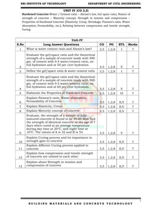
  • 1. NRI INSTITUTE OF TECHNOLOGY DEPARTMENT OF CIVIL ENGINEERING 1 B U I L D I N G M A T E R I A L S A N D C O N C R E T E T E C H N O L O G Y UNIT IV {CO 3,5} Hardened Concrete-Water / Cement ratio – Abram’s law, Gel space ratio, Nature of strength of concrete – Maturity concept, Strength in tension and compression – Properties of Hardened Concrete (Elasticity, Creep, Shrinkage, Poisson’s ratio, Water absorption, Permeability, etc.), Relating between compression and tensile strength, Curing Unit-IV S.No Long Answer Questions CO PO BTL Marks 1 What is water cement ratio and Abram’s law? 3,5 1,2,8 I 7 2 Evaluate the gel/space ratio and the theoretical strength of a sample of concrete made with 400 gm. of cement with 0.4 water/cement ratio, on full hydration and at 50 per cent hydration. 3,5 1,2,8 V 7 3 Define the gel/space ratio & water cement ratio 3,5 1,2,8 I 7 4 Evaluate the gel/space ratio and the theoretical strength of a sample of concrete made with 500 gm. of cement with 0.5 water/cement ratio, on full hydration and at 60 per cent hydration. 3,5 1,2,8 V 7 5 Elaborate the Properties of Hardened Concrete 3,5 1,2,8 VI 7 6 Explain Poisson’s ratio, Water absorption, Permeability of Concrete 3,5 1,2,8 II,V 7 7 Explain Elasticity, Creep 3,5 1,2,8 II,V 7 8 Explain Maturity concept of concrete 3,5 1,2,8 II,V 7 9 Evaluate, the strength of a sample of fully matured concrete is found to be 40.00 Mpa find the strength of identical concrete at the age of 7 days when cured at an average temperature during day time at 20°C, and night time at 10°C. The values of A is 32 and B is 54. 3,5 1,2,8 V 7 10 Explain Curing process and its importance in strength gain to concrete 3,5 1,2,8 II,V 7 11 Explain different Curing process applied to concrete 3,5 1,2,8 II,V 7 12 Explain how compression and tensile strength of concrete are related to each other 3,5 1,2,8 II,V 7 13 Explain about Strength in tension and compression of concrete 3,5 1,2,8 II,V 7
  • 2. NRI INSTITUTE OF TECHNOLOGY DEPARTMENT OF CIVIL ENGINEERING 2 B U I L D I N G M A T E R I A L S A N D C O N C R E T E T E C H N O L O G Y Water/Cement Ratio Strength of concrete primarily depends upon the strength of cement paste. It has been discussed that the strength of cement paste depends upon the dilution of paste or in other words, the strength of paste increases with cement content and decreases with air and water content. In 1918 Duff Abrams presented his classic law in the form: S = where x =water/cement ratio by volume and For 28 days results the constants A and B are 14,000 lbs/sq. in. or 96.6 Mpa and 7 respectively. 1 Pounds per square inch (lbs/sq. in. ) = 0.0069 Megapascals Abram’s water/cement ratio law states that the strength of concrete is only dependent upon water/cement ratio provided the mix is workable. In the past many theories have been propounded by many research workers. Some of them held valid for some time and then underwent some changes while others did not stand the test of time and hence slowly disappeared. But Abrams’ water/cement ratio law stood the test of time and is held valid even today as a fundamental truth in concrete-making practices. No doubt some modifications have been suggested but the truth of the statement could not be challenged. Strictly speaking, it was Feret who formulated in as early as 1897, a general rule defining the strength of the concrete paste and concrete in terms of volume fractions of the constituents by the equation: S = K where S = Strength of concrete c, e and a = volume of cement, water and air respectively and K = a constant. In this expression the volume of air is also included because it is not only the water/ cement ratio but also the degree of compaction, which indirectly means the volume of air-filled voids in the concrete is taken into account in estimating the strength of concrete.
  • 3. NRI INSTITUTE OF TECHNOLOGY DEPARTMENT OF CIVIL ENGINEERING 3 B U I L D I N G M A T E R I A L S A N D C O N C R E T E T E C H N O L O G Y The relation between the water/cement ratio and strength of concrete is shown in Fig. 7.1. It can be seen that lower water/cement ratio could be used when the concrete is vibrated to achieve higher strength, whereas comparatively higher water/cement ratio is required when concrete is hand compacted. In both cases when the water/cement ratio is below the practical limit the strength of the concrete falls rapidly due to introduction of air voids. The graph showing the relationship between the strength and water/cement ratio is approximately hyperbolic in shape. Fig. Shows the relationship between compressive strength and cement/water ratio. Sometimes it is difficult to interpolate the intermediate value. From geometry it can be deduced that if the graphs is drawn between the strength and the cement/water ratio an approximately linear relationship will be obtained. This linear relationship is more convenient to use than water/cement ratio curve for interpolation. Gel/Space Ratio
  • 4. NRI INSTITUTE OF TECHNOLOGY DEPARTMENT OF CIVIL ENGINEERING 4 B U I L D I N G M A T E R I A L S A N D C O N C R E T E T E C H N O L O G Y Many research workers commented on the validity of water/cement ratio law as propounded by Duff Abrams. They have forwarded a few of the limitations of the water/ cement ratio law and argued that “Abram’s water/cement ratio law can only be called a rule and not a law because Abrams’ statement does not include many qualifications necessary for its validity to call it a law.” Some of the limitations are  That the strength at any water/cement ratio depends on the degree of hydration of cement and its chemical and physical properties,  The temperature at which the hydration takes place,  The air content in case of air entrained concrete,  The change in the effective water/cement ratio and  The formation of fissures and cracks due to bleeding or shrinkage. Instead of relating the strength to water/cement ratio, the strength can be more correctly related to the solid products of hydration of cement to the space available for formation of this product. Powers and Brownyard have established the relationship between the strength and Gel/space ratio. This ratio is defined as the ratio of the volume of the hydrated cement paste to the sum of volumes of the hydrated cement and of the capillary pores. Power’s experiment showed that the strength of concrete bears a specific relationship with the gel/space ratio. He found the relationship to be S = 240 x3 Where x is the gel/space ratio and 240 represents the intrinsic strength of the gel in MPa for the type of cement and specimen used. The strength calculated by Power’s expression holds good for an ideal case. It is pointed out that the relationship between the strength and water/cement ratio will hold good primarily for 28 days strength for fully compacted concrete, whereas, the relationship between the strength and gel/space ratio is independent of age. Gel/space ratio can be calculated at any age and for any fraction of hydration of cement. The following examples show how to calculate the gel/space ratio.
  • 5. NRI INSTITUTE OF TECHNOLOGY DEPARTMENT OF CIVIL ENGINEERING 5 B U I L D I N G M A T E R I A L S A N D C O N C R E T E T E C H N O L O G Y Fig. Shows the relationship between strength and gel/space ratio. Calculation of gel/space ratio for complete hydration Let C = weight of cement in gm. VC = specific volume of cement = 0.319 ml/gm. WO = volume of mixing water in ml. Assuming that 1 ml. of cement on hydration will produce 2.06 ml of gel, Volume of gel = C x 0.319 x 2.06 = 0.657 C Space available = C x 0.319 + WO ∴ Gel/Space ratio = x = 𝑽𝒐𝒍𝒖𝒎𝒆 𝒐𝒇 𝑮𝒆𝒍 𝑺𝒑𝒂𝒄𝒆 𝑨𝒗𝒂𝒊𝒍𝒂𝒃𝒍𝒆 ∴ Gel/Space ratio = x = 𝟎.𝟔𝟓𝟕 𝑪 𝟎.𝟑𝟏𝟗 𝑪 𝑾𝟎 Calculation of gel/space ratio for partial hydration Let α = Fraction of cement that has hydrated Volume of gel = C x α x 0.319 x 2.06 = 0.657C α Total space available = C VC α + WO ∴ Gel/Space ratio = x = 𝑽𝒐𝒍𝒖𝒎𝒆 𝒐𝒇 𝑮𝒆𝒍 𝑺𝒑𝒂𝒄𝒆 𝑨𝒗𝒂𝒊𝒍𝒂𝒃𝒍𝒆 ∴ Gel/Space ratio = x = 𝟎.𝟔𝟓𝟕 𝑪𝜶 𝟎.𝟑𝟏𝟗 𝑪𝜶 𝑾𝟎 Example: 1
  • 6. NRI INSTITUTE OF TECHNOLOGY DEPARTMENT OF CIVIL ENGINEERING 6 B U I L D I N G M A T E R I A L S A N D C O N C R E T E T E C H N O L O G Y Calculate the gel/space ratio and the theoretical strength of a sample of concrete made with 500 gm. of cement with 0.5 water/cement ratio, on full hydration and at 60 per cent hydration. Gel/space ratio on full hydration = x = 𝑽𝒐𝒍𝒖𝒎𝒆 𝒐𝒇 𝑮𝒆𝒍 𝑺𝒑𝒂𝒄𝒆 𝑨𝒗𝒂𝒊𝒍𝒂𝒃𝒍𝒆 Gel/Space ratio on full hydration = x = 𝟎.𝟔𝟓𝟕 𝑪 𝟎.𝟑𝟏𝟗 𝑪 𝑾𝟎 Given 500 gm. of cement with 0.5 water/cement ratio Gel/Space ratio on full hydration = x = 𝟎.𝟔𝟓𝟕∗𝟓𝟎𝟎 𝟎.𝟑𝟏𝟗∗𝟓𝟎𝟎 (𝟎.𝟓∗𝟓𝟎𝟎) x = 0.802 say 0.8 Theoretical strength of concrete = S = 240 x3 = 240 x (0.8)3 ∴ Theoretical strength of concrete on full hydration = S = 123 Mpa Gel/space ratio for 60 percent hydration. Let α = Fraction of cement that has hydrated = 60 % = 60/100 = 0.6 Volume of gel = C x α x 0.319 x 2.06 = 0.657C α Total space available = C VC α + WO Gel/Space ratio = x = 𝑽𝒐𝒍𝒖𝒎𝒆 𝒐𝒇 𝑮𝒆𝒍 𝑺𝒑𝒂𝒄𝒆 𝑨𝒗𝒂𝒊𝒍𝒂𝒃𝒍𝒆 Gel/Space ratio for 60 percent hydration = x = 𝟎.𝟔𝟓𝟕 𝑪𝜶 𝟎.𝟑𝟏𝟗 𝑪𝜶 𝑾𝟎 = 𝟎.𝟔𝟓𝟕∗𝟓𝟎𝟎∗𝟎.𝟔 (𝟎.𝟑𝟏𝟗∗𝟓𝟎𝟎∗𝟎.𝟔) (𝟓𝟎𝟎∗𝟎.𝟓) Gel/Space ratio for 60 percent hydration = x = 0.57 Theoretical strength of concrete at 60 per cent hydration = S = 240 x3 =240 x (0.57)3 ∴ Theoretical strength of concrete at 60 per cent hydration = 44.4 MPa Example: 2
  • 7. NRI INSTITUTE OF TECHNOLOGY DEPARTMENT OF CIVIL ENGINEERING 7 B U I L D I N G M A T E R I A L S A N D C O N C R E T E T E C H N O L O G Y Calculate the gel/space ratio and the theoretical strength of a sample of concrete made with 450 gm. of cement with 0.45 water/cement ratio, on full hydration and at 55 per cent hydration. a) Gel/space ratio on full hydration Volume of gel = C x 0.319 x 2.06 = 0.657C Total space available = C VC + WO Gel/space ratio on full hydration = x = 𝑽𝒐𝒍𝒖𝒎𝒆 𝒐𝒇 𝑮𝒆𝒍 𝑺𝒑𝒂𝒄𝒆 𝑨𝒗𝒂𝒊𝒍𝒂𝒃𝒍𝒆 Gel/Space ratio on full hydration = x = 𝟎.𝟔𝟓𝟕 𝑪 𝟎.𝟑𝟏𝟗 𝑪 𝑾𝟎 Given 450 gm. of cement with 0.45 water/cement ratio Gel/Space ratio on full hydration = x = 𝟎.𝟔𝟓𝟕∗𝟒𝟓𝟎 𝟎.𝟑𝟏𝟗∗𝟒𝟓𝟎 (𝟎.𝟒𝟓∗𝟒𝟓𝟎) x = 0.854 say 0.85 Theoretical strength of concrete = S = 240 x3 = 240 x (0.85)3 ∴ Theoretical strength of concrete on full hydration = S = 149.66 Mpa b) Gel/space ratio for 55 percent hydration. Let α = Fraction of cement that has hydrated = 55 % = 55/100 = 0.55 Volume of gel = C x α x 0.319 x 2.06 = 0.657C α Total space available = C VC α + WO Gel/Space ratio = x = 𝑽𝒐𝒍𝒖𝒎𝒆 𝒐𝒇 𝑮𝒆𝒍 𝑺𝒑𝒂𝒄𝒆 𝑨𝒗𝒂𝒊𝒍𝒂𝒃𝒍𝒆 Gel/Space ratio for 60 percent hydration = x = 𝟎.𝟔𝟓𝟕 𝑪𝜶 𝟎.𝟑𝟏𝟗 𝑪𝜶 𝑾𝟎 = 𝟎.𝟔𝟓𝟕∗𝟒𝟓𝟎∗𝟎.𝟓𝟓 (𝟎.𝟑𝟏𝟗∗𝟒𝟓𝟎∗𝟎.𝟓𝟓) (𝟒𝟓𝟎∗𝟎.𝟒𝟓) Gel/Space ratio for 60 percent hydration = x = 0.577 Theoretical strength of concrete at 60 per cent hydration = S = 240 x3 =240 x (0.577)3 ∴ Theoretical strength of concrete at 60 per cent hydration = 46.28 MPa Example: 3
  • 8. NRI INSTITUTE OF TECHNOLOGY DEPARTMENT OF CIVIL ENGINEERING 8 B U I L D I N G M A T E R I A L S A N D C O N C R E T E T E C H N O L O G Y Calculate the gel/space ratio and the theoretical strength of a sample of concrete made with 550 gm. of cement with cement/water ratio as 2, on full hydration and at 70 per cent hydration. a) Gel/space ratio on full hydration Volume of gel = C x 0.319 x 2.06 = 0.657C Total space available = C VC + WO Gel/space ratio on full hydration = x = 𝑽𝒐𝒍𝒖𝒎𝒆 𝒐𝒇 𝑮𝒆𝒍 𝑺𝒑𝒂𝒄𝒆 𝑨𝒗𝒂𝒊𝒍𝒂𝒃𝒍𝒆 Gel/Space ratio on full hydration = x = 𝟎.𝟔𝟓𝟕 𝑪 𝟎.𝟑𝟏𝟗 𝑪 𝑾𝟎 Given 550 gm. of cement with cement/water ratio as 2 cement/water = 2 water (𝑾𝟎) = cement/ 2 = 550/2 = 275 Gel/Space ratio on full hydration = x = 𝟎.𝟔𝟓𝟕∗𝟓𝟓𝟎 𝟎.𝟑𝟏𝟗∗𝟓𝟓𝟎 𝟐𝟕𝟓 x = 0.80 Theoretical strength of concrete = S = 240 x3 = 240 x (0.80)3 ∴ Theoretical strength of concrete on full hydration = S = 124 Mpa b) Gel/space ratio for 70 percent hydration. Let α = Fraction of cement that has hydrated = 70 % = 70/100 = 0.70 Volume of gel = C x α x 0.319 x 2.06 = 0.657C α Total space available = C VC α + WO Gel/Space ratio = x = 𝑽𝒐𝒍𝒖𝒎𝒆 𝒐𝒇 𝑮𝒆𝒍 𝑺𝒑𝒂𝒄𝒆 𝑨𝒗𝒂𝒊𝒍𝒂𝒃𝒍𝒆 Gel/Space ratio for 60 percent hydration = x = 𝟎.𝟔𝟓𝟕 𝑪𝜶 𝟎.𝟑𝟏𝟗 𝑪𝜶 𝑾𝟎 = 𝟎.𝟔𝟓𝟕∗𝟓𝟓𝟎∗𝟎.𝟕 (𝟎.𝟑𝟏𝟗∗𝟓𝟓𝟎∗𝟎.𝟕) (𝟐𝟕𝟓) Gel/Space ratio for 60 percent hydration = x = 0.6358 Theoretical strength of concrete at 60 per cent hydration = S = 240 x3 =240 x (0.6358)3 ∴ Theoretical strength of concrete at 60 per cent hydration = 61.7 MPa
  • 9. NRI INSTITUTE OF TECHNOLOGY DEPARTMENT OF CIVIL ENGINEERING 9 B U I L D I N G M A T E R I A L S A N D C O N C R E T E T E C H N O L O G Y There is a lot of difference between the theoretical strength of concrete and actual strength of concrete. Actual strength of concrete is much lower than the theoretical strength estimated on the basis of molecular cohesion and surface energy of a solid assumed to be perfectly homogeneous and flawless. The actual reduction of strength is due to the presence of flaws. Griffith postulated his theory on the flaws in concrete. He explains that the flaws in concrete lead to a high stress concentration in the material under load, so that a very high stress is reached in and around the flaws with the result that the material gets fractured around this flaw while the average stress on the material, taking the cross section of the material as a whole, remains comparatively low. The flaws vary in size. The high stress concentration takes place around a few of the larger flaws. This situation leads to failure of the material at a much lower stress intensity considering the whole process. Presence of bigger flaws brings down the actual strength to a much lower value than the theoretical strength. Cement paste in concrete contains many discontinuities such as voids, fissures, bleeding channels, rupture of bond due to drying shrinkage and temperature stresses etc. It has been difficult to explain how exactly these various flaws contribute to the reduction in actual strength of concrete. However, Griffith’s theory which explains the failure of concrete has been accepted to satisfactorily explain the failure of brittle materials such as concrete. Maturity Concept of Concrete While dealing with curing and strength development, we have so far considered only the time aspect. It has been pointed out earlier that it is not only the time but also the temperature during the early period of hydration that influence the rate of gain of strength of concrete. Since the strength development of concrete depends on both time and temperature it can be said that strength is a function of summation of product of time and temperature. This summation is called maturity of concrete. Maturity = Σ (time x temperature)
  • 10. NRI INSTITUTE OF TECHNOLOGY DEPARTMENT OF CIVIL ENGINEERING 10 B U I L D I N G M A T E R I A L S A N D C O N C R E T E T E C H N O L O G Y The temperature is reckoned from an origin lying between –12 and –10°C. It was experimentally found that the hydration of concrete continues to take place up to about –11°C. Therefore, –11°C is taken as a datum line for computing maturity. Maturity is measured in degree centigrade hours (°C hrs) or degree centigrade days (°C days). Fig. 7.6. shows that the strength plotted against the logarithm of maturity gives a straight line. A sample of concrete cured at 18°C for 28 days is taken as fully matured concrete. Its maturity would be equal to Maturity of concrete at the age of 28 days = Σ (time x Temperature) 28 x 24 x [18 – (–11)] = 19488°C h. However, in standard calculations the maturity of fully cured concrete is taken as 19,800°Ch. (The discrepancy is because of the origin or the datum is not exactly being –11 0C as used in calculation). If the period is broken into smaller intervals and if the corresponding temperature is recorded for each interval of time, the summation of the product of time and temperature will give an accurate picture of the maturity of concrete. In the absence of such detailed temperature history with respect to the time interval, the maturity figure can be arrived at by multiplying duration in hours by
  • 11. NRI INSTITUTE OF TECHNOLOGY DEPARTMENT OF CIVIL ENGINEERING 11 B U I L D I N G M A T E R I A L S A N D C O N C R E T E T E C H N O L O G Y the average temperature at which the concrete is cured. Of course, the maturity calculated as above will be less accurate. Maturity concept is useful for estimating the strength of concrete at any other maturity as a percentage of strength of concrete of known maturity. In other words, if we know the strength of concrete at full maturity (19,800°Ch), we can calculate the percentage strength of identical concrete at any other maturity by using the following equation given by Plowman. Strength at any maturity as a percentage of strength at maturity of 19,800°Ch= A + B log10 {(maturity) / 1000} The values of coefficients, A and B depend on the strength level of concrete. The values are given in Table 7.5 The values of A and B are plotted against the cube strength at the maturity of 19,800° Ch. A straight line relationship will be obtained indicating that they are directly proportional to the strength. Plowman divided the strength into 4 zones as shown in Table 7.5 and has assigned the values of A and B for each zone. It is to be noted that the maturity equation holds good for the initial temperature of concrete less than about 38°C. Fig. 7.7 gives the value of constant A and B when strength and temperature are expressed in lbs./squinch and °F respectively.
  • 12. NRI INSTITUTE OF TECHNOLOGY DEPARTMENT OF CIVIL ENGINEERING 12 B U I L D I N G M A T E R I A L S A N D C O N C R E T E T E C H N O L O G Y Fig. 7.7 value of constant A and B when strength and temperature are expressed in lbs./squinch and °F respectively. The following examples illustrate the theory. Example 1: The strength of a sample of fully matured concrete is found to be 40.00 Mpa find the strength of identical concrete at the age of 7 days when cured at an average temperature during day time at 20°C, and night time at 10°C. Maturity of concrete at the age of 7 days = Σ (time x Temperature) M(t) = Σ (Ta – T0)* Δt = 7 x 12 x [20 – (–11)] + 7 x 12 x [10 – (– 11)] = 7 x 12 x 31 + 7 x 12 x 21 = 4368°Ch. The strength range of this concrete falls in Zone III for which the constant A is 32 and B is 54. ∴ The percentage strength of concrete at maturity of 4368°Ch. = A + B log 10 {(4368) /1000} = 32 + 54 x log10 (4.368) = 32 + 54 x 0.6403
  • 13. NRI INSTITUTE OF TECHNOLOGY DEPARTMENT OF CIVIL ENGINEERING 13 B U I L D I N G M A T E R I A L S A N D C O N C R E T E T E C H N O L O G Y = 66.5 Mpa Maturity concept is useful for estimating the strength of concrete at any other maturity as a percentage of strength of concrete of known maturity. ∴ The strength at 7 days = 40.0 x (66.5/100) = 26.5 Mpa Example: 2 Evaluate, the strength of a sample of fully matured concrete is found to be 50.00 Mpa find the strength of identical concrete at the age of 8 days when cured at an average temperature during day time at 25°C, and night time at 11°C. The values of A is 32 and B is 54 Maturity of concrete at the age of 8 days = Σ (time x Temperature) M(t) = Σ (Ta – T0) * Δt = 7 x 12 x [25 – (–11)] + 7 x 12 x [11 – (– 11)] = (7 x 12 x 36) + (7 x 12 x 22) = 4872 °Ch. Given , sample of fully matured concrete is found to be 50.00 Mpa The strength range of this concrete falls in Zone III for which the constant A is 32 and B is 54. ∴ The percentage strength of concrete at maturity of
  • 14. NRI INSTITUTE OF TECHNOLOGY DEPARTMENT OF CIVIL ENGINEERING 14 B U I L D I N G M A T E R I A L S A N D C O N C R E T E T E C H N O L O G Y 4872°Ch. = A + B log 10 {(4368) /1000} = 32 + 54 x log10 (4.872) = 32 + 54 x 0.687 = 69.13 Mpa Maturity concept is useful for estimating the strength of concrete at any other maturity as a percentage of strength of concrete of known maturity. ∴ The strength at 8 days = 50.0 x (69.13/100) = 34.56 Mpa Strength in tension and compression Concrete has been used for construction since Roman times. It is essentially artificial rock, made with a paste of cement and water to bind together some solid material like sand or gravel. Modern concrete is made with Portland cement, water, sand and some rock called aggregate. It is a versatile and durable building material, used in roadways, bridges, houses, commercial buildings and many other places. Properly installed and cured, it will last for years. Compression Concrete has enormous compressive strength, the ability to withstand heavy weights or forces on it. It also gains strength as it ages. Concrete will solidify in a few hours and harden or set in a few days, but continues to gain strength for at least 28 days. Some very thick concrete structures, like dams, will continue to gain strength for months or years.
  • 15. NRI INSTITUTE OF TECHNOLOGY DEPARTMENT OF CIVIL ENGINEERING 15 B U I L D I N G M A T E R I A L S A N D C O N C R E T E T E C H N O L O G Y Tension Concrete has almost no tensile strength, the ability to withstand pressing or stretching. Put a board between two supports and press down on the center. It will bend. The top of the board is under compression, the bottom which bends is under tension. Concrete can resist the compression, but will break under the tension. Concrete cracks in roads and slabs are largely due to tension; different weights in different areas produce tensile forces. Tension-Compression Ratio The tension to compression ratio for concrete is about 10 to 15 percent. That is, it can withstand about 10 times the pushing force or compression of the pulling force or tension. Both strengths increase with age, but the ratio is steady. Portland cement concrete less than a year old has compression strength of 1,000 pounds per square inch (psi) and tension strength of 200 psi. Concrete more than a year old has compression psi of 2,000 pounds and tension psi of 400. Reinforcing To give concrete tensile strength -- to support beams in a bridge or building, for instance -- reinforcing steel is added.
  • 16. NRI INSTITUTE OF TECHNOLOGY DEPARTMENT OF CIVIL ENGINEERING 16 B U I L D I N G M A T E R I A L S A N D C O N C R E T E T E C H N O L O G Y Steel has great tensile strength; it bends without breaking. The combination produces the strength needed for bridge girders, roadways, building walls and other construction. An even stronger combination is prestressed concrete. The reinforcing steel is stretched or put under tension before concrete is poured around it. When tension is released, the tendency of the steel to return to its unstretched form adds reverse tension which strengthens a concrete beam or girder. Relation Between Compressive and Tensile Strength In reinforced concrete construction the strength of the concrete in compression is only taken into consideration. The tensile strength of concrete is generally not taken into consideration. But the design of concrete pavement slabs is often based on the flexural strength of concrete.
  • 17. NRI INSTITUTE OF TECHNOLOGY DEPARTMENT OF CIVIL ENGINEERING 17 B U I L D I N G M A T E R I A L S A N D C O N C R E T E T E C H N O L O G Y Therefore, it is necessary to assess the flexural strength of concrete either from the compressive strength or independently. As measurements and control of compressive strength in field are easier and more convenient, it has been customary to find out the compressive strength for different conditions and to correlate this compressive strength to flexural strength. Having established a satisfactory relationship between flexural and compressive strength, pavement, can be designed for a specified flexural strength value, or this value could be used in any other situations when required. It is seen that strength of concrete in compression and tension (both direct tension and flexural tension) are closely related, but the relationship is not of the type of direct proportionality. The ratio of the two strengths depends on general level of strength of concrete. In other words, for higher compressive strength concrete shows higher tensile strength, but the rate of increase of tensile strength is of decreasing order. The type of coarse aggregate influences this relationship. Crushed aggregate gives relatively higher flexural strength than compressive strength. This is attributed to the improved bond strength between cement paste and aggregate particles.
  • 18. NRI INSTITUTE OF TECHNOLOGY DEPARTMENT OF CIVIL ENGINEERING 18 B U I L D I N G M A T E R I A L S A N D C O N C R E T E T E C H N O L O G Y The tensile strength of concrete, as compared to its compressive strength, is more sensitive to improper curing. This may be due to the inferior quality of gel formation as a result of improper curing and also due to the fact that improperly cured concrete may suffer from more shrinkage cracks. “The use of pozzolanic material increases the tensile strength of concrete.” From the extensive study, carried out at Central Road Research Laboratory (CRRI) the following statistical relationship between tensile strength and compressive strength were established. (i) y = 15.3x – 9.00 for 20 mm maximum size aggregate. (ii) y = 14.1x – 10.4 for 20 mm maximum size natural gravel. (iii) y = 9.9x – 0.55 for 40 mm maximum size crushed aggregate. (iv) y = 9.8x – 2.52 for 40 mm maximum size natural gravel. Where y is the compressive strength of concrete MPa and x is the flexural strength of concrete MPa. Subjecting all the data to statistical treatment the following general relationship has been established at CRRI between flexural and compressive strength of concrete: y = 11x – 3.4 The flexural to compressive strength ratio was higher with aggregate of 40 mm maximum size than with those of 20 mm maximum size. In general, the ratio was found to be slightly higher in the case of natural gravel as compared to crushed stone.
  • 19. NRI INSTITUTE OF TECHNOLOGY DEPARTMENT OF CIVIL ENGINEERING 19 B U I L D I N G M A T E R I A L S A N D C O N C R E T E T E C H N O L O G Y Fig. shows the relationships between compressive strength and flexural strength of concrete for various aggregates. The flexural strength of concrete was found to be 8 to 11 per cent of the compressive strength of the concrete for higher ranges of concrete strength (greater than 25 MPa) and 9 to 12.8 per cent for lower ranges of concrete strength (less than 25 MPa) as shown in Table 7.6. Flexural strength of concrete is usually found by testing plain concrete beams. Two methods of loading of the beam specimen for finding out flexural strength are practiced: Central point loading and third points loading Experience shows that the variability of results is less in third-point loading. The results of the flexural strength tested under central and third-points loading with constant span to depth ratios of 4 were analyzed statistically and the following general relationship was obtained at Central Road Research Laboratory. x1 = x2 + 0.72 where, x1 = flexural strength (MPa) of concrete under central point loading and x2 = flexural strength (MPa) of concrete under third point loading. In all the cases the central loading gave higher average value than the third- point loading irrespective of the size of the sample. The higher strength obtained in the case of central loading may be attributed to the fact that the beam is being subjected to the maximum stress at a pre-determined location not necessarily the weakest.
  • 20. NRI INSTITUTE OF TECHNOLOGY DEPARTMENT OF CIVIL ENGINEERING 20 B U I L D I N G M A T E R I A L S A N D C O N C R E T E T E C H N O L O G Y In the standard methods for finding the flexural strength of concrete, the span to depth ratio of the specimen is kept at 4. If the span to depth ratio is increased or decreased, the flexural strength was found to alter. A change in this ratio by one induced 3 per cent and 2.5 per cent change in strength when tested by third-point and central point loading respectively. With the increase in span to depth ratio the flexural strength decreased. The rate of stress application was found to influence the flexural strength of concrete to a very significant extent. The strength increased up to about 25 per cent with increase in stressing rate compared to the standard rate of 0.7 MPa per minute. The increase was found more with the leaner mixes. There are number of empirical relationships connecting tensile strength and compressive strength of concrete. One of the common relationships is shown below. where, value of K varies from 6.2 for gravels to K varies from 10.4 for crushed rock (average value of K is 8.3) and value of n may vary from 1/2 to 3/4 Further data obtained at the Laboratories of Portland Cement Association giving the relationship between compressive and tensile strength of concrete is shown in Table 7.7. The Indian Standard IS 456 of 2000 gives the following relationship between the compressive strength and flexural strength where fck is the characteristic compressive strength of concrete @ 28 days in N/mm2
  • 21. NRI INSTITUTE OF TECHNOLOGY DEPARTMENT OF CIVIL ENGINEERING 21 B U I L D I N G M A T E R I A L S A N D C O N C R E T E T E C H N O L O G Y Testing of hardened concrete plays an important role in controlling and confirming the quality of cement concrete works. Systematic testing of raw materials, fresh concrete and hardened concrete are inseparable part of any quality control program for concrete, which helps to achieve higher efficiency of the material used and greater assurance of the performance of the concrete with regard to both strength and durability. The test methods should be simple, direct and convenient to apply. One of the purposes of testing hardened concrete is to confirm that the concrete used at site has developed the required strength. As the hardening of the concrete takes time, one will not come to know, the actual strength of concrete for some time. This is an inherent disadvantage in conventional test. But, if strength of concrete is to be known at an early period, accelerated strength test can be carried out to predict 28 days strength. But mostly when correct materials are used and careful steps are taken at every stage of the work, concretes normally give the required strength. The tests also have a deterring effect on those responsible for construction work. The results of the test on hardened concrete, even if they are known late, helps to reveal the quality of concrete and enable adjustments to be made in the production of further concretes. Tests are made by casting cubes or cylinder from the representative concrete or cores cut from the actual concrete. It is to be remembered that standard compression test specimens give a measure of the potential strength of the concrete, and not of the strength of the concrete in structure. Knowledge of the strength of concrete in structure cannot be directly obtained from tests on separately made specimens.
  • 22. NRI INSTITUTE OF TECHNOLOGY DEPARTMENT OF CIVIL ENGINEERING 22 B U I L D I N G M A T E R I A L S A N D C O N C R E T E T E C H N O L O G Y Properties of Hardened Concrete Permeability: Hardened Concrete has a tendency to become porous due to the presence of voids formed during or after placing of concrete. Penetration by the substance may adversely affect the durability, i.e. Ca(OH)2 leach out and corrosion occurs due to lack of air and moisture. The liquid retaining structure is important in relation to water tightness. To produce concrete of low permeability, complete compaction and proper curing are necessary while low permeability is important to enhancing resistance to frost action, chemical attack, and protecting embedded steel against corrosion. The permeability of cement paste varies with the progress of hydration or with age, the permeability decreases as the gel slowly fills the original waterlogged space. For the same w / c ratio, the permeability of the paste with coarse cement particles is higher than that of fine cement. In general, the higher the strength of cement paste, the lower the permeability. Factors influencing permeability of hardened concrete are as follows: i. W/C Ratio. ii. Curing. iii. Method of compaction. iv. Workability. v. Soundness & porosity of the aggregate. vi. Age. (permeability decrease with age) vii. Grading of aggregate. viii. Types of structures. Shrinkage: Concrete is subjected to changes in volume either autogenous or induced. Volume change is one of the most detrimental properties of concrete, which affects the long-term strength and durability. To the practical engineer, the aspect of volume change in concrete is important from the point of view that it causes unsightly cracks in concrete.
  • 23. NRI INSTITUTE OF TECHNOLOGY DEPARTMENT OF CIVIL ENGINEERING 23 B U I L D I N G M A T E R I A L S A N D C O N C R E T E T E C H N O L O G Y It is caused by the disposal of solids and the loss of water free from plastic concrete (plastic shrinkage), by the chemical combination of cement with water and by the drying (drying shrinkage) of concrete. Shrinkage depends on the amount of drying that can take place. Affected by the humidity and temperature of the surrounding air, the rate of airflow on the surface and surface area to volume of concrete Shrinkage Concrete is subjected to either autogenous or induced volume changes. Volume change is one of the most damaging properties of concrete, affecting long-term strength and durability. For the practical engineer, the aspect of volume change in concrete is important from the point of view that it produces unsightly cracks in the concrete.
  • 24. NRI INSTITUTE OF TECHNOLOGY DEPARTMENT OF CIVIL ENGINEERING 24 B U I L D I N G M A T E R I A L S A N D C O N C R E T E T E C H N O L O G Y Hard concrete undergoes three types of shrinkage that are important with respect to its dimensional stability: 1. Plastic shrinkage. 2. Drying Shrinkage. 3. Thermal shrinkage. 1. Plastic shrinkage: It is the shrinkage that freshly placed concrete passes through until it is completely set. It can also be called initial shrinkage. There is such a major volumetric change from evaporation, bleeding, seepage and soaking by the formwork to water loss from fresh concrete. Excessive shrinkage in the initial stages may develop extensive cracking in the concrete at the setting. Therefore, all precautions should be taken to avoid excessive loss of water due to evaporation. 2. Drying Shrinkage: As the concrete is completely set and hardened, some further shrinkage may result in moisture, or further loss of drying, due to contraction of the gel-structure. Such shrinkage is practically an essential and irreversible property of concrete. Careful design of reinforcement has to be met to avoid its side effects. 3. Thermal shrinkage: This may be due to a drop in the temperature of the concrete being held until it is fully set. Thus, when the concrete is placed at 30 ° C, cooled to 15 ° –18 ° C, some shrinkage can be expected. This may be negligible in its account. But when drying is added to shrinkage, it becomes necessary. Creep Concrete creep is defined as: deformation of structure under sustained load. Basically, long term pressure or stress on concrete can make it change shape. This deformation usually occurs in the direction the force is being applied. Like a concrete column getting more compressed, or a beam bending. Creep does not necessarily cause concrete to fail or break apart. When a load is applied to concrete, it experiences an instantaneous elastic strain which develops into creep strain if the load is sustained. Creep is factored in when concrete structures are designed. Factors Affecting Creep Aggregate Mix Proportions Age of concrete
  • 25. NRI INSTITUTE OF TECHNOLOGY DEPARTMENT OF CIVIL ENGINEERING 25 B U I L D I N G M A T E R I A L S A N D C O N C R E T E T E C H N O L O G Y The magnitude of creep strain is one to three times the value of the instantaneous elastic strain, it is proportional to cement-paste content and, thus, inversely proportional to aggregate volumetric content. The magnitude of creep is dependent upon the magnitude of the applied stress, the age and strength of the concrete, properties of aggregates and cementitious materials, amount of cement paste, size and shape of concrete specimen, volume to surface ratio, amount of steel reinforcement, curing conditions, and environmental conditions. 1. Influence of Aggregate Aggregate undergoes very little creep. It is really the paste which is responsible for the creep. However, the aggregate influences the creep of concrete through a restraining effect on the magnitude of creep. The paste which is creeping under load is restrained by aggregate which do not creep. The stronger the aggregate the more is the restraining effect and hence the less is the magnitude of creep. An increase from 65 to 75 % of volumetric content of the aggregate will decrease the creep by 10 %. The modulus of elasticity of aggregate is one of the important factors influencing creep. It can be easily imagined that the higher the modulus of elasticity the less is the creep. Light weight aggregate shows substantially higher creep than normal weight aggregate. 2. Influence of Mix Proportions: The amount of paste content and its quality is one of the most important factors influencing creep. A poorer paste structure undergoes higher creep. Therefore, it can be said that creep increases with increase in water/cement ratio. In other words, it can also be said that creep is inversely proportional to the strength of concrete. Broadly speaking, all other factors which are affecting the water/cement ratio are also affecting the creep. 3. Influence of Age: Age at which a concrete member is loaded will have a predominant effect on the magnitude of creep. This can be easily understood from the fact that the quality of gel improves with time. Such gel creeps less, whereas a young gel under load being not so stronger creeps more. What is said above is not a very accurate statement because of the fact that the moisture content of the concrete being different at different age also influences the magnitude of creep.
  • 26. NRI INSTITUTE OF TECHNOLOGY DEPARTMENT OF CIVIL ENGINEERING 26 B U I L D I N G M A T E R I A L S A N D C O N C R E T E T E C H N O L O G Y Effects of Creep on Concrete and Reinforced Concrete  In reinforced concrete beams, creep increases the deflection with time and may be a critical consideration in design.  In eccentrically loaded columns, creep increases the deflection and can load to buckling.  In case of statically indeterminate structures and column and beam junctions creep may relieve the stress concentration induced by shrinkage, temperatures changes or movement of support. Creep property of concrete will be useful in all concrete structures to reduce the internal stresses due to non- uniform load or restrained shrinkage.  In mass concrete structures such as dams, on account of differential temperature conditions at the interior and surface, creep is harmful and by itself may be a cause of cracking in the interior of dams. Therefore, all precautions and steps must be taken to see that increase in temperature does not take place in the interior of mass concrete structure.  Loss of prestress due to creep of concrete in prestressed concrete structure.  Because of rapid construction techniques, concrete members will experience loads that can be as large as the design loads at very early age; these can cause deflections due to cracking and early age low elastic modulus.  So, creep has a significant effect on both the structural integrity and the economic impact that it will produce if predicted wrong. Modulus of Elasticity Modulus of elasticity of concrete (Ec) is defined as the ratio of the applied stress to the corresponding strain. Not only does it demonstrate the ability of concrete to withstand deformation due to applied stress but also its stiffness. In other words, it reflects the ability of concrete to deflect elastically. Modulus of elasticity of concrete is sensitive to aggregate and mixture proportions of concrete.
  • 27. NRI INSTITUTE OF TECHNOLOGY DEPARTMENT OF CIVIL ENGINEERING 27 B U I L D I N G M A T E R I A L S A N D C O N C R E T E T E C H N O L O G Y In the design of concrete structures, modulus of elasticity is considerably important that requires to be defined. The linear analysis of elements, which is based on elastic theory, is used in some cases to satisfy requirements of ultimate and serviceability limit state such as in the design of pre-stressed concrete structures. Common applicable codes around the world such as ACI Code, European Code, British Standards, Canadian standard association, and Indian standard have provided a formula for the computation of elastic modulus of concrete. Calculation of Elastic Modulus of Concrete The computation of modulus of elasticity of concrete using IS 456 Concrete modulus of elasticity based on Indian standard can be calculated using the following expression: equation 9 Importance in Design of Concrete Structure It is highly crucial to define modulus of elasticity of concrete in the design of concrete structure. Linear analysis of elements, which is based on the theory of elasticity, is used to satisfy requirements of both ultimate and serviceability limit state for instance in the case of pre-stressed concrete that demonstrate uncracked section up to the failure. In addition to compute deflections which are required to be limited under the serviceability requirements in all structures. Finally, knowledge of the modulus of elasticity of high strength concrete is very important in avoiding excessive deformation providing satisfactory serviceability and avoiding the most cost-effective designs. Poisson's ratio Poisson's ratio of concrete is the ratio of transverse strain to longitudinal strain in concrete specimen subjected to axial loads. The longitudinal strain and vertical strain are produced due to concrete volume reduction under compression load. Volume reduction of concrete specimen is the result of crushing small aggregate sizes due to exerted loads. Poisson’s ratio of concrete is a constant for determining the stress and deflection properties of structures such as beams, plates, and shells Longitudinal and Transverse Stress in Concrete Specimen Under Loads
  • 28. NRI INSTITUTE OF TECHNOLOGY DEPARTMENT OF CIVIL ENGINEERING 28 B U I L D I N G M A T E R I A L S A N D C O N C R E T E T E C H N O L O G Y Fig. 1: Longitudinal and Transverse Stress in Concrete Specimen Under Loads What is Poisson's Ratio of concrete?  The value of concrete Poisson’s ratio is possible to vary based on the type of specimen (dry, wet, or saturated), and loading conditions.  Comparatively, Poisson’s ratio of concrete under static loads is lower than that of concrete upon which dynamic loads are applied.  The concrete Poisson’s ratio under dynamic loads varies mostly between 0.20 to 0.25.  By and large, it ranges from 0.1 for high strength concrete to 0.2 for low strength concrete.  For design of concrete structures, the most common value of concrete Poisson’s ratio is taken as 0.2.  It is recommended to practice great cautions to ensure that Poisson’s ratio is compatible with values used for shear modulus of elasticity of concrete otherwise serious errors may be encountered.  Poisson's ratio of concrete is constant up to about 70% of strength.  It can be computed from static modulus test.  Poisson's ratio can be determined dynamically from ultra sonic pulse velocity and from fundamental resonant frequency of longitudinal vibration of concrete beam. Water absorption One of the most important properties of a good quality concrete is low permeability, especially one resistant to freezing and thawing. A concrete with low permeability resists ingress of water and is not as susceptible to freezing and thawing. Water enters pores in the cement paste and even in the aggregate. Absorption Water absorption is defined as the amount of water absorbed by a material and is calculated as the ratio of the weight of water absorbed to the weight of the dry material. For concrete pavers, the test procedure involves drying a specimen to a constant weight, weighing it, immersing it in water for specified amount of time, and weighing it again. The increase in weight as a percentage of the original weight is expressed as its absorption (in percent). The average absorption of the test samples shall not be greater than 5% with no individual unit greater than 7%. Effect of water absorption in concrete
  • 29. NRI INSTITUTE OF TECHNOLOGY DEPARTMENT OF CIVIL ENGINEERING 29 B U I L D I N G M A T E R I A L S A N D C O N C R E T E T E C H N O L O G Y This absorbs moisture and causes efflorescence or the accumulation of salts in the water. For example, if a floor covering is laid over wet concrete or water from an original mixing or drainage problem comes through, the unprotected material absorbs moisture, expands, and destroys the floor. Curing of Concrete We have discussed in Chapter I the hydration aspect of cement. Concrete derives its strength by the hydration of cement particles. The hydration of cement is not a momentary action but a process continuing for long time. Of course, the rate of hydration is fast to start with, but continues over a very long time at a decreasing rate. The quantity of the product of hydration and consequently the amount of gel formed depends upon the extent of hydration. It has been mentioned earlier that cement requires a water/cement ratio about 0.23 for hydration and a water/cement ratio of 0.15 for filling the voids in the gel pores. In other words, a water/cement ratio of about 0.38 would be required to hydrate all the particles of cement and also to occupy the space in the gel pores. Theoretically, for a concrete made and contained in a sealed container a water cement ratio of 0.38 would satisfy the requirement of water for hydration and at the same time no capillary cavities would be left. Fig.6.24. Cracks on concrete surface due to inadequate curing. (Fig. 6.24, shows plastic shrinkage cracks on concrete surface due to quick drying and inadequate early curing.) However, it is seen that practically a water/cement ratio of 0.5 will be required for complete hydration in a sealed container for keeping up the desirable relative humidity level. In the field and in actual work, it is a different story. Even though a higher water/cement ratio is used, since the concrete is open to atmosphere, the water
  • 30. NRI INSTITUTE OF TECHNOLOGY DEPARTMENT OF CIVIL ENGINEERING 30 B U I L D I N G M A T E R I A L S A N D C O N C R E T E T E C H N O L O G Y used in the concrete evaporates and the water available in the concrete will not be sufficient for effective hydration to take place particularly in the top layer. Fig. 5.33 on page 173, Chapter 5, shows the drying behaviour of concrete. If the hydration is to continue unbated, extra water must be added to replenish the loss of water on account of absorption and evaporation. Alternatively, some measures must be taken by way of provision of impervious covering or application of curing compounds to prevent the loss of water from the surface of the concrete. Therefore, the curing can be considered as creation of a favourable environment during the early period for uninterrupted hydration. The desirable conditions are, a suitable temperature and ample moisture. Curing can also be described as keeping the concrete moist and warm enough so that the hydration of cement can continue. More elaborately, it can be described as the process of maintaining a satisfactory moisture content and a favourable temperature in concrete during the period immediately following placement, so that hydration of cement may continue until the desired properties are developed to a sufficient degree to meet the requirement of service. Hessian cloth
  • 31. NRI INSTITUTE OF TECHNOLOGY DEPARTMENT OF CIVIL ENGINEERING 31 B U I L D I N G M A T E R I A L S A N D C O N C R E T E T E C H N O L O G Y Fig. 6.25 shows the influence of curing by ponding and wet covering. Curing is being given a place of increasing importance as the demand for high quality concrete is increasing. It has been recognized that the quality of concrete shows all round improvement with efficient uninterrupted curing. If curing is neglected in the early period of hydration, the quality of concrete will experience a sort of irreparable loss. An efficient curing in the early period of hydration can be compared to a good and wholesome feeding given to a new born baby. A concrete laid in the afternoon of a hot summer day in a dry climatic region, is apt to dry out quickly. The surface layer of concrete exposed to acute drying condition, with the combined effect of hot sun and drying wind is likely to be made up of poorly hydrated cement with inferior gel structure which does not give the desirable bond and strength characteristics. In addition, the top surface, particularly that of road or floor pavement is also subjected to a large magnitude of plastic shrinkage stresses. The dried concrete naturally being weak, cannot withstand these stresses with the result that innumerable cracks develop at the surface Fig. 6.24, shows plastic shrinkage cracks on concrete surface due to quick drying and inadequate early curing. The top surface of such hardened concrete on account of poor gel structure, suffers from lack of wearing quality and abrasion resistance.
  • 32. NRI INSTITUTE OF TECHNOLOGY DEPARTMENT OF CIVIL ENGINEERING 32 B U I L D I N G M A T E R I A L S A N D C O N C R E T E T E C H N O L O G Y Therefore, such surfaces create mud in the rainy season and dust in summer. The quick surface drying of concrete results in the movement of moisture from the interior to the surface. This steep moisture gradient cause high internal stresses which are also responsible for internal micro cracks in the semi-plastic concrete. Concrete, while hydrating, releases high heat of hydration. This heat is harmful from the point of view of volume stability. If the heat generated is removed by some means, the adverse effect due to the generation of heat can be reduced. This can be done by a thorough water curing. Fig. 6.25, shows the influence of curing by ponding and wet covering.6.4 Curing Methods Curing methods may be divided broadly into four categories: (a) Water curing (b) Membrane curing (c) Application of heat (d) Miscellaneous Water Curing This is by far the best method of curing as it satisfies all the requirements of curing, namely, promotion of hydration, elimination of shrinkage and absorption of the heat of hydration. It is pointed out that even if the membrane method is adopted, it is desirable that a certain extent of water curing is done before the concrete is covered with membranes. Water curing can be done in the following ways: (a) Immersion (b) Ponding (c) Spraying or Fogging (d) Wet covering The precast concrete items are normally immersed in curing tanks for a certain duration. Pavement slabs, roof slab etc. are covered under water by making small ponds. Vertical retaining wall or plastered surfaces or concrete columns etc. are cured by spraying water. In some cases, wet coverings such as wet gunny bags, hessian cloth, jute matting, straw etc., are wrapped to vertical surface for keeping the concrete wet. For horizontal surfaces saw dust, earth or sand are used as wet covering to keep the concrete in wet condition for a longer time so that the concrete is not unduly dried to prevent hydration. Membrane Curing
  • 33. NRI INSTITUTE OF TECHNOLOGY DEPARTMENT OF CIVIL ENGINEERING 33 B U I L D I N G M A T E R I A L S A N D C O N C R E T E T E C H N O L O G Y Sometimes, concrete works are carried out in places where there is acute shortage of water. The lavish application of water for water curing is not possible for reasons of economy. It has been pointed out earlier that curing does not mean only application of water; it means also creation of conditions for promotion of uninterrupted and progressive hydration. It is also pointed out that the quantity of water, normally mixed for making concrete is more than sufficient to hydrate the cement, provided this water is not allowed to go out from the body of concrete. For this reason, concrete could be covered with membrane which will effectively seal off the evaporation of water from concrete. It is found that the application of membrane or a sealing compound, after a short spell of water curing for one or two days is sometimes beneficial. Sometimes, concrete is placed in some inaccessible, difficult or far off places. The curing of such concrete cannot be properly supervised. The curing is entirely left to the workmen, who do not quite understand the importance of regular uninterrupted curing. In such cases, it is much safer to adopt membrane curing rather than to leave the responsibility of curing to workers. Large number of sealing compounds have been developed in recent years. The idea is to obtain a continuous seal over the concrete surface by means of a firm impervious film to prevent moisture in concrete from escaping by evaporation. Sometimes, such films have been used at the interface of the ground and concrete to prevent the absorption of water by the ground from the concrete. Some of the materials, that can be used for this purpose are bituminous compounds, polyethylene or polyester film, waterproof paper, rubber compounds etc. Bituminous compound being black in colour, absorbs heat when it is applied on the top surface of the concrete. This results in the increase of temperature in the body of concrete which is undesirable. For this purpose, other modified materials which are not black in colour are in use. Such compounds are known as “Clear Compounds”. It is also suggested that a lime wash may be given over the black coating to prevent heat absorption. Membrane curing is a good method of maintaining a satisfactory state of wetness in the body of concrete to promote continuous hydration when original water/cement ratio used is not less than 0.5. To achieve best results, membrane is applied after one or two days of actual wet curing.
  • 34. NRI INSTITUTE OF TECHNOLOGY DEPARTMENT OF CIVIL ENGINEERING 34 B U I L D I N G M A T E R I A L S A N D C O N C R E T E T E C H N O L O G Y Membrane curing by spraying. Since no replenishing of water is done after the membrane has been applied it should be ensured that the membrane is of good quality and it is applied effectively. Two or three coats may be required for effective sealing of the surface to prevent the evaporation of water. Enough has been written in Chapter 5 on the modern curing compounds that are available today. Increase in volume of construction, shortage of water and need for conservation of water, increase in cost of labour and availability of effective curing compounds have encouraged the use of curing compounds in concrete construction. Curing compound is an obvious choice for curing canal lining, sloping roofs and textured surface of concrete pavements. It is seen that there are some fear and apprehension in the mind of builders and contractors regarding the use of membrane forming curing compounds. No doubt that curing compounds are not as efficient and as ideal as water curing. The efficiency of curing compounds can be at best be 80% of water curing. But this 80% curing is done in a fool proof manner. Although water curing is ideal in theory, it is often done intermittently and hence, in reality the envisaged advantage is not there, in which case membrane curing may give better results. For further details refer Chapter 5 where more information about curing compounds. Method for determining the efficiency of curing compounds etc., are given. When waterproofing paper or polyethylene film are used as membrane, care must be taken to see that these are not punctured anywhere and also see whether adequate lapping is given at the junction and this lap is effectively sealed. Membrane Forming Curing Compounds In view of insufficient curing generally carried out at site of work, the increasing importance of curing for around good qualities of concrete, in particular,
  • 35. NRI INSTITUTE OF TECHNOLOGY DEPARTMENT OF CIVIL ENGINEERING 35 B U I L D I N G M A T E R I A L S A N D C O N C R E T E T E C H N O L O G Y strength and durability, the need for conservation of water and common availability of curing compounds in the country, it is felt that detail information is required on this vital topic – curing of concrete by membrane forming curing compounds. Availability of enough moisture in concrete is the essence for uninterrupted hydration process. In fresh concrete, the moisture level in concrete is much higher than the relative humidity of atmosphere. Therefore, evaporation of water takes place from the surface of concrete. To recoup the loss of water from the surface of concrete and to prevent the migration of water from the interior of concrete to surface of concrete, that is to retain adequate moisture in the concrete, certain measures are adopted. Such measures taken are generally called curing of concrete. Drying Behaviour Drying behaviour of concrete depends upon air temperature, relative humidity, fresh concrete temperature and wind velocity. Figure 5.33 shows drying behaviour as per Learch’s investigation. The sketch is self-explanatory. Types of Curing Compounds Liquid membrane forming curing compounds are used to retard the loss of water from concrete during the early period of setting and hardening. They are used not only for curing fresh concrete, but also for further curing of concrete after removal of form work or after initial water curing for one or two days. In the case of white pigmented curing compound, it also reduces the temperature rise in concrete exposed to radiation from sun. Curing compounds are made with the following bases. " Synthetic resin " Wax " Acrylic " Chlorinated rubber. Resin and wax based curing compounds seal the concrete surface effectively. With time their efficiency will get reduced and at about 28 days they get disintegrated and peels off. Plastering can be done after about 28 days. If plastering is required to be done earlier, the surface can be washed off with hot water. As per one set of experiments it has been revealed that the typical curing efficiency was 96% for 24 hours, 84% for 72 hours 74% for 7 days and 65% for 14 days and the average efficiency of resin and wax based membrane forming curing compound can be taken as about 80%. Acrylic based membrane forming curing compound has the additional advantage of having better adhesion of subsequent plaster. The membrane does not
  • 36. NRI INSTITUTE OF TECHNOLOGY DEPARTMENT OF CIVIL ENGINEERING 36 B U I L D I N G M A T E R I A L S A N D C O N C R E T E T E C H N O L O G Y get crumbled down or it need not be washed with hot water. In fact, on account of inherent characteristics of acrylic emulsion the bonding for the plaster is better. Chlorinated rubber curing compounds not only form a thin film that protects the concrete from drying out but also fill the minute pores in the surface of concrete. The surface film will wear out eventually. Application of heat The development of strength of concrete is a function of not only time but also that of temperature. When concrete is subjected to higher temperature it accelerates the hydration process resulting in faster development of strength. Concrete cannot be subjected to dry heat to accelerate the hydration process as the presence of moisture is also an essential requisite. Therefore, subjecting the concrete to higher temperature and maintaining the required wetness can be achieved by subjecting the concrete to steam curing. A faster attainment of strength will contribute to many other advantages mentioned below. (a) Concrete is vulnerable to damage only for short time. (b) Concrete member can be handled very quickly. (c) Less space will be sufficient in the casting yerd. (d) A smaller curing tank will be sufficient. (e) A higher outturn is possible for a given capital outlay. (f) The work can be put on to service at a much early time, (g) A fewer number of formworks will be sufficient or alternatively with the given number of formworks more outturn will be achieved. (h) Prestressing bed can be released early for further casting. Curing vertical surface by wet covering. From the above-mentioned advantages, it can be seen that steam curing will give not only economic advantages, but also technical advantages in the matter of prefabrication of concrete elements.
  • 37. NRI INSTITUTE OF TECHNOLOGY DEPARTMENT OF CIVIL ENGINEERING 37 B U I L D I N G M A T E R I A L S A N D C O N C R E T E T E C H N O L O G Y The exposure of concrete to higher temperature is done in the following manner: (a) Steam curing at ordinary pressure. (b) Steam curing at high pressure. (c) Curing by Infra-red radiation. (d) Electrical curing. Steam curing at ordinary pressure This method of curing is often adopted for prefabricated concrete elements. Application of steam curing to in situ construction will be a little difficult task. However, at some places it has been tried for in situ construction by forming a steam jacket with the help of tarpaulin or thick polyethylene sheets. But this method of application of steam for in situ work is found to be wasteful and the intended rate of development of strength and benefit is not really achieved. Beam under steam curing. The influence of curing temperature on strength of concrete is shown in Fig. 6.26
  • 38. NRI INSTITUTE OF TECHNOLOGY DEPARTMENT OF CIVIL ENGINEERING 38 B U I L D I N G M A T E R I A L S A N D C O N C R E T E T E C H N O L O G Y Fig. 6.27 One Day Strength increases with increasing curing temperature but 28 days strength decreases with increasing curing temperature The influence of curing temperature on strength of concrete is shown in Fig. 6.28
  • 39. NRI INSTITUTE OF TECHNOLOGY DEPARTMENT OF CIVIL ENGINEERING 39 B U I L D I N G M A T E R I A L S A N D C O N C R E T E T E C H N O L O G Y Figure 6.29 shows the effect of temperature on strength of concrete. Fig. 6.30 Gain of Strength of Steam Cured Concrete with Time
  • 40. NRI INSTITUTE OF TECHNOLOGY DEPARTMENT OF CIVIL ENGINEERING 40 B U I L D I N G M A T E R I A L S A N D C O N C R E T E T E C H N O L O G Y Fig. 6.31 A typical steam curing cycle at ordinary pressure is shown Steam curing at ordinary pressure is applied mostly on prefabricated elements stored in a chamber. The chamber should be big enough to hold a day’s production. The door is closed and steam is applied. The steam may be applied either continuously or intermittently. An accelerated hydration takes place at this higher temperature and the concrete products attain the 28 days strength of normal concrete in about 3 days. In large prefabricated factories they have tunnel curing arrangements. The tunnel of sufficient length and size is maintained at different temperature starting from a low temperature in the beginning of the tunnel to a maximum temperature of about 90°C at the end of the tunnel. The concrete products mounted on trollies move in a very slow speed subjecting the concrete products progressively to higher and higher temperature. Alternatively, the trollies are kept stationarily at different zones for some period and finally come out of tunnel. The influence of curing temperature on strength of concrete is shown in Fig. 6.26 and 6.28.6.5 It is interesting to note that concrete subjected to higher temperature at the early period of hydration is found to lose some of the strength gained at a later age. Such concrete is said to undergo “Retrogression of Strength”. Figure 6.29 shows the effect of temperature on strength of concrete. It can be seen from Figure 6.29 that the concrete subjected to higher temperature at early age, no doubt attains higher strength at a shorter duration, but suffers considerable
  • 41. NRI INSTITUTE OF TECHNOLOGY DEPARTMENT OF CIVIL ENGINEERING 41 B U I L D I N G M A T E R I A L S A N D C O N C R E T E T E C H N O L O G Y retrogression of strength. Fig. 6.29. On the contrary, concrete cured at a comparatively lower temperature takes longer time to develop strength but the strength attained will not be lost at later ages. The phenomenon of retrogression of strength explains that faster hydration will result in the formation of poor-quality gels with porous open structure, whereas the gel formed slowly but steadily at lower temperature are of good quality which are compact and dense in nature. This aspect can be compared to the growth of wood cells. It is common knowledge that a tree which grows faster, will yield timber of poor and non-durable quality, whereas a tree, which grows slowly will yield good durable timber. Similarly, concrete subjected to higher temperature in the early period of hydration will yield poor quality gels and concrete which is subjected to rather low temperature (say about 13 degree Centigrade) will yield the best quality gel, and hence good concrete. It has been emphasized that a very young concrete should not be subjected suddenly to high temperature. Certain amount of delay period on casting the concrete is desirable. It has been found that if 49°C is reached in a period shorter than 2 to 3 hours or 99°C is reached in less than 6 to 7 hours from the time of mixing, the gain of strength beyond the first few hours is affected adversely. The strength of such rapidly heated concrete falls in the zone B and the strength of gradually heated concrete falls within the zone A in Figure. 6.30. Concrete subjected to steam curing exhibits a slightly higher drying shrinkage and moisture movement. Subjecting the concrete to higher temperature may also slightly affect the aggregate quality in case of some artificial aggregate. Steam curing of concrete made with rapid hardening cement will generate a much higher heat of hydration. Similarly, richer mixes may have more adverse effect than that of lean mixes.
  • 42. NRI INSTITUTE OF TECHNOLOGY DEPARTMENT OF CIVIL ENGINEERING 42 B U I L D I N G M A T E R I A L S A N D C O N C R E T E T E C H N O L O G Y Fig. 6.32. Typical strength of steam cured concrete at different temperature In India, steam curing is often adopted for precast elements, especially prestressed concrete sleepers. Concrete sleepers are being introduced on the entire Indian Railway. For rapid development of strength, they use special type of cement namely IRST 40 and also subject the sleepers to steam curing. Large number of bridges are being built for infrastructural development in India. There are requirements for casting of innumerable precast prestressed girders. These girders are steam cured for faster development of strength which has many other associated advantages. A steam-curving cycle consists of: " an initial delay prior to steaming, " a period for increasing the temperature, " a period for retaining the temperature, " a period for decreasing the temperature. A typical steam curing cycle at ordinary pressure is shown Fig. 6.31and typical strength of steam cured concrete at different temperature in shown in Fig. 6.32. High Pressure Steam Curing
  • 43. NRI INSTITUTE OF TECHNOLOGY DEPARTMENT OF CIVIL ENGINEERING 43 B U I L D I N G M A T E R I A L S A N D C O N C R E T E T E C H N O L O G Y In the steam curing at atmospheric pressure, the temperature of the steam is naturally below 100°C. The steam will get converted into water, thus it can be called in a way, as hot water curing. This is done in an open atmosphere. The high-pressure steam curing is something different from ordinary steam curing, in that the curing is carried out in a closed chamber. The superheated steam at high pressure and high temperature is applied on the concrete. This process is also called “Autoclaving”. The autoclaving process is practised in curing precast concrete products in the factory, particularly, for the lightweight concrete products. In India, this high- pressure steam curing is practised in the manufacture of cellular concrete products, such as Siporex, Celcrete etc. The following advantages are derived from high pressure steam curing process: (a) High pressure steam cured concrete develops in one day, or less the strength as much as the 28 days’ strength of normally cured concrete. The strength developed does not show retrogression. (b) High pressure steam cured concrete exhibits higher resistance to sulphate attack, freezing and thawing action and chemical action. It also shows less efflorescence. (c) High pressure steam cured concrete exhibits lower drying shrinkage, and moisture movement. In high pressure steam curing, concrete is subjected to a maximum temperature of about 175°C which corresponds to a steam pressure of about 8.5 kg/sq.cm. When the concrete is to be subjected to high pressure steam curing, it is invariably made by admixing with 20 to 30 per cent of pozzolanic material such as crushed stone dust. In case of normal curing, the liberation of Ca (OH)2 is a slow process. Therefore, when pozzolanic materials are added, the pozzolanic reactivity also will be a slow process. But in case of high-pressure steam curing a good amount of Ca (OH)2 will be liberated in a very short time and reaction between Ca (OH)2 and pozzolanic material takes place in an accelerated manner. A good amount of technical advantage is achieved by admixing the concrete with pozzolanic material. High pressure steam curing exhibits higher strength and durability particularly in the case of cement containing a proportionately higher amount of C3S. A sample of cement containing higher proportion of C2S is not benefited to the same extent, as it produces lower amount of Ca (OH)2 It is also observed that
  • 44. NRI INSTITUTE OF TECHNOLOGY DEPARTMENT OF CIVIL ENGINEERING 44 B U I L D I N G M A T E R I A L S A N D C O N C R E T E T E C H N O L O G Y improvement in durability is more for the concrete made with higher water/cement ratio, than for the concrete made with low water/cement ratio. Owing to the combination of Ca (OH)2 with siliceous material within a matter of 24 hours in the case of high steam curing, concrete becomes impervious and hence durable. The fact is that the concrete in the absence of free Calcium Hydroxide becomes dense and less permeable, and also accounts for higher chemical resistance and higher strength. The higher rate of development of strength is attributed to the higher temperature to which a concrete is subjected. Earlier it is brought out that if the concrete is subjected to very high temperature, particularly in the early period of hydration, most of the strength gained will be lost because of the formation of poor- quality gel. The above is true for steam cured concrete at atmospheric pressure. The high- pressure steam cured concrete does not exhibit retrogression of strength. The possible explanation is that in the case of high-pressure steam curing, the quality and uniformity of pore structure formed is different. At high temperature the amorphous calcium silicates are probably converted to crystalline forms. Probably due to high pressure the frame work of the gel will become more compact and denser. This perhaps explains why the retrogression of strength does not take place in the case of high-pressure steam curing. In ordinarily cured concrete, the specific surface of the gel is estimated to be about two million sq. cm per gram of cement, whereas in the case of high-pressure steam cured concrete, the specific surface of gel is in the order of seventy thousand sq. cm per gram. In other words, the gels are about 20 times coarser than ordinarily cured concrete. It is common knowledge, that finer material shrinks more than coarser material. Therefore, ordinary concrete made up of finer gels shrinks more than high pressure steam cured concrete made up of coarser gel. In quantitative terms, the high-pressure steam cured concrete undergoes shrinkage of 1/3 to 1/6 of that of concrete cured at normal temperature. When pozzolanic material is added to the mix, the shrinkage is found to be higher, but still, it shrinks only about 1/2 of the shrinkage of normally cured concrete. Due to the absence of free calcium hydroxide no efflorescence is seen in case of high-pressure steam cured concrete. Due to the formation of coarser gel, the bond strength of concrete to the reinforcement is reduced by about 30 per cent to 50 per
  • 45. NRI INSTITUTE OF TECHNOLOGY DEPARTMENT OF CIVIL ENGINEERING 45 B U I L D I N G M A T E R I A L S A N D C O N C R E T E T E C H N O L O G Y cent when compared with ordinary moist-cured concrete. High pressure steam cured concrete is rather brittle and whitish in colour. On the whole, high pressure steam curing produces good quality dense and durable concrete: The concrete products as moulded with only a couple of hours delay period is subjected to maximum temperature over a period of 3 to 5 hours. This is followed by about 5 to 8 hours at this temperature. Pressure and temperature are released in about one hour. The detail steaming cycle depends on the plant, quality of material thickness of member etc. The length of delay period before subjecting to high pressure steam curing does not materially affect the quality of high-pressure steam cured concrete. Curing by Infra-red Radiation Curing of concrete by Infra-red Radiation has been practised in very cold climatic regions in Russia. It is claimed that much more rapid gain of strength can be obtained than with steam curing and that rapid initial temperature does not cause a decrease in the ultimate strength as in the case of steam curing at ordinary pressure.
  • 46. NRI INSTITUTE OF TECHNOLOGY DEPARTMENT OF CIVIL ENGINEERING 46 B U I L D I N G M A T E R I A L S A N D C O N C R E T E T E C H N O L O G Y The system is very often adopted for the curing of hollow concrete products. The normal operative temperature is kept at about 90°C. Electrical Curing Another method of curing concrete, which is applicable mostly to very cold climatic regions is the use of electricity. This method is not likely to find much application in ordinary climate owing to economic reasons. Concrete can be cured electrically by passing an alternating current (Electrolysis trouble will be encountered if direct current is used) through the concrete itself between two electrodes either buried in or applied to the surface of the concrete.
  • 47. NRI INSTITUTE OF TECHNOLOGY DEPARTMENT OF CIVIL ENGINEERING 47 B U I L D I N G M A T E R I A L S A N D C O N C R E T E T E C H N O L O G Y Care must be taken to prevent the moisture from going out leaving the concrete completely dry. As this method is not likely to be adopted in this country, for a long time to come, this aspect is not discussed in detail. Miscellaneous Methods of Curing Calcium chloride is used either as a surface coating or as an admixture. It has been used satisfactorily as a curing medium. Both these methods are based on the fact that calcium chloride being a salt, shows affinity for moisture. The salt, not only absorbs moisture from atmosphere but also retains it at the surface. This moisture held at the surface prevents the mixing water from evaporation and thereby keeps the concrete wet for a long time to promote hydration. Formwork prevents escaping of moisture from the concrete, particularly, in the case of beams and columns. Keeping the formwork intact and sealing the joint with wax or any other sealing compound prevents the evaporation of moisture from
  • 48. NRI INSTITUTE OF TECHNOLOGY DEPARTMENT OF CIVIL ENGINEERING 48 B U I L D I N G M A T E R I A L S A N D C O N C R E T E T E C H N O L O G Y the concrete. This procedure of promoting hydration, can be considered as one of the miscellaneous methods of curing. When to Start Curing and how Long to Cure? Many a time an engineer at site wonders, how early he should start curing by way of application of water. This problem arises, particularly, in case of hot weather concreting. In an arid region, concrete placed as a road slab or roof slab gets dried up in a very short time, say within 2 hours. Often questions are asked whether water can be poured over the above concrete within two hours to prevent the drying. The associated problem is, if water is applied within say two hours, whether it will interfere with the water/cement ratio and cause harmful effects. In other words, question is how early water can be applied over concrete surface so that uninterrupted and continued hydration takes place, without causing interference with the water/cement ratio. The answer is that first of all, concrete should not be allowed to dry fast in any situation. Concrete that are liable to quick drying is required to be covered with wet gunny bag or wet hessian cloth properly squeezed, so that the water does not drip and at the same time, does not allow the concrete to dry. This condition should be maintained for 24 hours or at least till the final setting time of cement at which duration the concrete will have assumed the final volume. Even if water is poured, after this time, it is not going to interfere with the water/cement ratio. However, the best practice is to keep the concrete under the wet gunny bag for 24 hours and then commence water curing by way of ponding or spraying. Of course, when curing compound is used immediately after bleeding water, if any, dries up, the question of when to start water curing does not arise at all. There is a wrong notion with common builders that commencement of curing should be done only on the following day after concreting. Even on the next day they make arrangements and build bunds with mud or lean mortar to retain water. This further delay the curing. Such practice is followed for concrete road construction by municipal corporations also. It is a bad practice. It is difficult to set time frame how early water curing can be started. It depends on, prevailing temperature, humidity, wind velocity,
  • 49. NRI INSTITUTE OF TECHNOLOGY DEPARTMENT OF CIVIL ENGINEERING 49 B U I L D I N G M A T E R I A L S A N D C O N C R E T E T E C H N O L O G Y type of cement, fineness of cement, w/c used and size of member etc. The point to observe is that, the top surface of concrete should not be allowed to dry. Enough moisture must be present to promote hydration. To satisfy the above conditions any practical steps can be undertaken, including the application of fine spray or fogging without disturbing surface finish. Such measures may be taken as early as two hours after casting. It is pointed out that early curing is important for 53 grade cement. Incidentally, it is seen that test cubes cast at site are allowed to dry without covering the top with wet covering. They are allowed to dry in the hot sun. Such cubes develop cracks and show low strength when crushed. It is usual that they complain about poor quality of cement or concrete. Regarding how long to cure, it is again difficult to set a limit. Since all the desirable properties of concrete are improved by curing, the curing period should be as long as practical. For general guidance, concrete must be cured till it attains about 70% of specified strength. At lower temperature curing period must be increased. Since the rate of hydration is influenced by cement composition and fineness, the curing period should be prolonged for concretes made with cements of slow strength gain characteristics. Pozzolanic cement or concrete admixed with pozzolanic material is required to be cured for longer duration. Mass concrete, heavy footings, large piers, abutments, should be cured for at least 2 weeks. To ascertain the period of curing or stripping of formwork, cubes or beams are cast and kept adjacent to the structure they represent and cured by the same method. The strength of these cubes or beams at different intervals of time would give better idea about the strength development of structures. The above method does not truly indicate the strength development of massive girder subjected to steam curing because of size difference of cubes and girders. Finishing
  • 50. NRI INSTITUTE OF TECHNOLOGY DEPARTMENT OF CIVIL ENGINEERING 50 B U I L D I N G M A T E R I A L S A N D C O N C R E T E T E C H N O L O G Y Finishing operation is the last operation in making concrete. Finishing in real sense does not apply to all concrete operations. For a beam concreting, finishing may not be applicable, whereas for the concrete road pavement, airfield pavement or for the flooring of a domestic building, careful finishing is of great importance. Concrete is often dubbed as a drab material, incapable of offering pleasant architectural appearance and finish. This shortcoming of concrete is being rectified and concretes these days are made to exhibit pleasant surface finishes. Particularly, many types of prefabricated concrete panels used as floor slab or wall unit are made in such a way as to give very attractive architectural affect. Even concrete claddings are made to give attractive look. In recent years there has been a growing tendency to develop and use various surface treatments which permit concrete structures to proudly proclaim its nature instead of covering itself with an expensive veneer. The property of concrete to reproduce form markings such as board mark finishes, use of linings or special types of formworks, special techniques for the application of applied finishes have been encouraged. Surface finishes may be grouped as under: (a) Formwork Finishes (b) Surface Treatment (c) Applied Finishes. Formwork Finishes Concrete obeys the shape of formwork i.e., centering work. By judiciously assembling the formwork either in plane surface or in undulated fashion or having the joints in a particular “V” shaped manner to get regular fins or groves, a pleasing surface finish can be given to concrete. The architect’s imaginations can be fully exploited to give many varieties of look to the concrete surface. The use of small battens can give a good look to the concrete surface. A pre-fabricated wall unit cast between steel formwork having very smooth surface using right proportioning of materials can give such a nice surface which can never be obtained by the best masons. Similarly, the prefabricated floor units can have such a fine finish at the ceiling which cannot be obtained by the best masons with the best efforts. These days with the cost of labour going up, attention is naturally directed to the self- finishing of the concrete surface, particularly, for floor slabs, by the use of good formwork material such as steel sheets or shuttering type plywood. Surface Treatment
  • 51. NRI INSTITUTE OF TECHNOLOGY DEPARTMENT OF CIVIL ENGINEERING 51 B U I L D I N G M A T E R I A L S A N D C O N C R E T E T E C H N O L O G Y This is one of the widely used methods for surface finishing. The concrete pavement slab is required to be plane but rough to exhibit skid resistance, so is the air-field pavements and road slabs. Concrete having been brought to the plane level surface, is raked lightly or broomed or textured or scratched to make the surface rough. A domestic floor slab is required to be smooth, wear resisting and crack-free. Mechanical trowel for finishing factory floor. Sometimes surface hardener is sprinkled and finished. The technique of finishing the concrete floor requires very careful considerations. The proportioning of the mix must be appropriate without excess or deficient of matrix. Water/ cement ratio should be such that it provides the just required consistency to facilitate spreading and good levelling, yet to give no bleeding. Surface must be finished at the same rate as the placing of concrete. Particular care must be taken to the extent and time of trowelling. Use of wooden float is better to start with but at the end steel trowel may be used. In all the operation, care must be taken to see that no laitance is formed and no excessive mortar or water accumulates on the surface of the floor, which reduces the wear resistance of the floor.
  • 52. NRI INSTITUTE OF TECHNOLOGY DEPARTMENT OF CIVIL ENGINEERING 52 B U I L D I N G M A T E R I A L S A N D C O N C R E T E T E C H N O L O G Y The excess of mortar at the surface causes craziness due to increased shrinkage. Achieving a good surface finish to a concrete floor requires considerable experience and devotion on the part of the mason. A hurried completion of surface operation will make a poor surface. Often concrete is placed at a much faster rate than the speed of finish by the masons with the result that concrete dries up and mason is not able to bring the concrete to a good level. He resorts to applying extra rich mortar to bring the floor surface to good level. This practice of applying rich mortar specially made to the surface is not desirable. This practice, firstly reduces the bond. Secondly, reduces the strength and wear resistance than the homogeneous concrete. Thirdly, mortar shrinks more than that of concrete. Therefore, application of a thick layer of mortar over set concrete is objectionable. It is a good practice to the finish the floor with the matrix that comes to the top of the concrete due to the compaction of concrete and by working with mason’s tamping rule. In case the above is not possible, use of extra mortar may be permitted to avoid very poor surface finish. But it is necessary to observe the following precautions: (a) The mortar composition be the same as that of concrete. (b) It should be applied as thin a layer as possible before the base concrete is hardened, and rubbed smooth. (c) Sprinkling of dry cement in good quantity is not a good practice, however a small quantity may be permitted to reduce the bad effect of bleeding, taking care to see that it does not make the top layer too rich. Exposed Aggregate-Finish: This is one of the methods of giving good look to the concrete surface. The beauty can be further enhanced by the use of coloured pebbles or quartz. One or two days after casting, the matrix is removed by washing the surface with water or by slight brushing and washing. One face of the aggregate particles will adhere to the matrix and the other face gets exposed. This exposed surface will give a pleasing look. Sometimes, retarding agent is applied to the formwork surface. The matrix at the surface being in contact with the retarding agent, does not get hardened, whereas rest of the portion gets hardened. On washing or light brushing, the unhardened matrix gets washed out, exposing the aggregate. Sometimes use of hydrochloric acid solution made up of one part of acid to six parts of water is used for washing the concrete surface to expose the aggregate. The acid attacks the cement and enables it to be brushed off. Care must be taken that
  • 53. NRI INSTITUTE OF TECHNOLOGY DEPARTMENT OF CIVIL ENGINEERING 53 B U I L D I N G M A T E R I A L S A N D C O N C R E T E T E C H N O L O G Y the workman should use rubber-gloves and on completion of washing by the acid, the surface should be treated with alkaline solution to neutralise any remaining acid. This method of using acid should not be applied for concrete made with limestone aggregate. Bush Hammering: A Bush Hammer is a tool with a series of pyramidal teeth on its face. They may be hand operated or pneumatically or electrically operated. Hand tools are suitable for small jobs but power operated equipment is used for large surface. Bush Hammer gives rapid blows to the concrete surface and not only removes the outer cement film but also breaks some of the exposed aggregate giving a bright, colourful and attractive surface. Very pleasant effects may be obtained by carefully arranging large aggregates at the surface and later removing the matrix by bush hammer. Concrete should be at least three weaks old, before it is bush hammered. Otherwise, there is a danger of whole pieces of aggregates being dislodged. The quality of concrete which is to be treated this way by bush hammering must be of high quality and good workmanship. Applied Finish: The term applied finish is used to denote the application of rendering to the exteriors of concrete structures. The concrete surface is cleaned and roughened and kept wet for sufficiently long time. Over this a mortar of proportion of about 1:3 is applied. This mortar rendering can be given any required pleasant finish, such as cement stippling either fine or coarse, combed finish, keying, renderings etc. Sometimes this rendering applied on wall is pressed with sponge. The sponge absorbs cement and water exposes sand particles. The sponge is washed and again rubbed against the surface. With the repetition of this process, the surface gets a finish, known as “Sand Facing”.
  • 54. NRI INSTITUTE OF TECHNOLOGY DEPARTMENT OF CIVIL ENGINEERING 54 B U I L D I N G M A T E R I A L S A N D C O N C R E T E T E C H N O L O G Y Sand Facing A wet plastic mix of three parts of cement, one part of lime, six parts of sand and 4 parts of about 5 mm size pea gravel aggregate is thrown against wall surface by means of a scoop or plasterer’s trowel. This finish is known as “Rough Cast Finish”. Rough Cast Finish Upon a 10 mm thick coat of one part of cement, one part of lime and five parts of sand, while it is still plastic, is thrown about 6 mm size selected well-washed pebbles. This kind of finish is known as “Pebble Dash”.
  • 55. NRI INSTITUTE OF TECHNOLOGY DEPARTMENT OF CIVIL ENGINEERING 55 B U I L D I N G M A T E R I A L S A N D C O N C R E T E T E C H N O L O G Y Pebble Dash Exposed aggregate finish The latest method of finish given to the concrete surface is known as “Fair Crete” finish. This rendering can be given to the concrete in situ or better still to the concrete panels. Such panels are used as cladding to the concrete structures. Fair Crete is nothing but a highly air-entrained mortar (air-entrainment is to be extent of 25 per cent) mixed with chopped jute fibre. This mortar is spread and pressed by a mould having different designs. The impression of the mould is translated into the mortar. Air entrained mortar being foamy in nature takes the impression of the mould. A wide variety of designs and murals can be translated to the air entrained mortar surface. The jute fibre increases the tensile strength of the fair Crete. Miscellaneous Finishes: Non-slip Finish: Surface of ramps, railway platforms, surroundings of swimming pools etc., are required to possess a highly nonslip texture. To obtain this quality, an abrasive grit is sprinkled over the surface during the floating operations. The surface is lightly floated just to embed the abrasive grit at the surface. Sometimes, epoxy screed is
  • 56. NRI INSTITUTE OF TECHNOLOGY DEPARTMENT OF CIVIL ENGINEERING 56 B U I L D I N G M A T E R I A L S A N D C O N C R E T E T E C H N O L O G Y also given to the surface over which silica sand is sprinkled while the epoxy is still wet. Coloured Finish: Principal materials used for colouring concrete are: (a) Pigment admixtures (b) Chemical stains (c) Paints (d) White cement (e) Coloured concrete. Pigment admixtures may be added integrally to the topping mix, blended with the dry cement, or pigments may be dusted on to the topping immediately on application of screed. Of all the methods, mixing integrally with the mortar is the best method, next to using coloured cements. Sometimes, certain chemicals are used to give desirable colour to the concrete surface. Similarly, cement-based paints or other colour paints are also used. White cement is used in different ways to give different look to the concrete. White and coloured cements have been used as toppings in factory floor finish. Recently RMC (India), a Ready-Mix Concrete supplying company, have started supplying Ready Mixed coloured concrete in various colours. They incorporate certain percentage of fibres in this concrete to take care of shrinkage cracks and to impart other desirable properties to the concrete. Such coloured concrete can be used indoors or out door application as a substitute to ordinary concrete. Wear Resistant Floor Finish: A wear resisting quality of a concrete floor surface can be improved by using solutions of certain chemicals known as “Liquid Hardeners”. They include, fluosilicates of magnesium and zinc, sodium silicate, gums and waxes. When the compounds penetrate the pores in the topping, they form crystalline or gummy deposits and thus tend to make the floor less pervious and reduce dusting either by acting as plastic binders or making the surface harder.
  • 57. NRI INSTITUTE OF TECHNOLOGY DEPARTMENT OF CIVIL ENGINEERING 57 B U I L D I N G M A T E R I A L S A N D C O N C R E T E T E C H N O L O G Y Applied finish work done at CME Sometimes, iron filing and iron chips are mixed with the toppings and the floor is made in a normal manner. The rusting of the iron filings and chips increases in volume and thereby makes the concrete dense giving the floor better wear resistance. They are known as “Ironite floor toppings”. Ironite Powder Ironite floor toppings
  • 58. NRI INSTITUTE OF TECHNOLOGY DEPARTMENT OF CIVIL ENGINEERING 58 B U I L D I N G M A T E R I A L S A N D C O N C R E T E T E C H N O L O G Y Fibre reinforced concrete also has demonstrated a better wear-resistance quality in case of road and airfield slabs. We have already discussed about Wear Resistant floor finish in Chapter 5 under construction chemicals. Attention is drawn to the present-day availability and application Epoxy Paint, Epoxy mortar, self- levelling Epoxy screed etc., for the use of Wear Resistant floor and decorative floor finish. They are widely used in modern construction. Requirement of a good finish: A good concrete floor should have a surface which is durable, non-absorptive, suitable texture, free from cracks, crazing and other defects. In other words, the floor should satisfactorily withstand wear from traffic. It should be sufficiently impervious to passage of water, oils or other liquids. It should possess a texture in keeping with the required appearance, should be easy to clean and be safe against slipping. It should structurally be sound and must act in unison with sub-floor. Grinding and Polishing: Floors when properly constructed using materials of good quality, are dustless, dense, easily cleaned and attractive in appearance. When grinding is specified, it should be started after the surface has hardened sufficiently to prevent dislodgement of aggregate particles and should be continued until the coarse aggregates are exposed. The machine used should be of approved type with stones that cut freely and rapidly. The floor is kept wet during the grinding process and the cuttings are removed by spraying and flushing with water. After the surface is ground, air holes, pits and the other blemishes are filled with a thin grout composed of one part of fine carborundum grit and one part of Portland cement. This grout is spread over the floor and worked into the pits with the straight edge after which it is rubbed into the floor with a grinding machine. When the fillings are hardened for seven days, the floor is given final grinding. Craziness: While we are discussing about the surface finish it will be pertinent to discuss the craziness i.e., the development of fine shallow hair cracks on concrete surface. The surface appearance of concrete is often spoilt by a fairly close pattern of hair cracks which may appear within the first year, occasionally after longer periods.
  • 59. NRI INSTITUTE OF TECHNOLOGY DEPARTMENT OF CIVIL ENGINEERING 59 B U I L D I N G M A T E R I A L S A N D C O N C R E T E T E C H N O L O G Y Craziness in the surface of concrete. The cracks do not penetrate deep into the concrete and do not indicate any structural weakness. They are most obvious immediately after the surface of the concrete has dried when wetted they become prominent. It is not possible to state any precautions which will definitely prevent craziness but its occurrence can be minimised. Craziness is due to drying shrinkage or carbonation or due to differential shrinkage between the surface of the concrete and the main body of the concrete. This differential shrinkage is accentuated if the skin is richer than the parent concrete. It is known that drying shrinkage is greatest when the concrete dries up fast after casting. The first precaution to take, therefore, is very careful curing so that the initial drying period is extended over as long a time as possible so that the shrinkage of the outer skin is kept in conformity with the shrinkage of the main body of the concrete. Steep moisture gradients between the surface and the interior of the concrete must be avoided if possible. Cracking will not occur if the concrete is sufficiently strong to resist the tensile forces caused by differential shrinkage but it does not appear possible to prevent crazing by making a very strong concrete. The object must therefore be to minimise shrinkage of the surface skin and this is best achieved by adequate curing and by taking measures to prevent shrinkage by avoiding too rich surface. The following precautions will help greatly: (a) Trowelling the surface as little as possible and in particular avoiding the use of a steel float. (b) Avoiding the use of rich facing mixes, say, not richer than 1:3. (c) Use of as low a water-cement ratio as possible consistent with adequate compaction. (d) Avoiding grouting processes or rubbing the surface with neat cement paste.