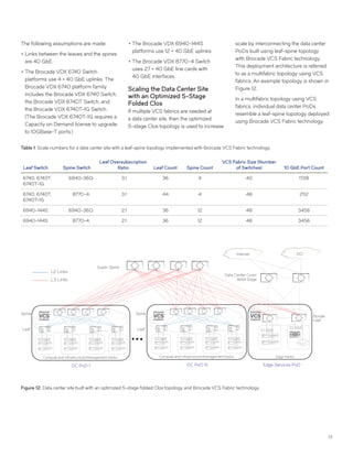
WHITE PAPER
Brocade Data Center Fabric Architectures
Building the foundation for a cloud-optimized data center
Based on the principles of the New IP, Brocade is building on the proven
success of the Brocade®
VDX®
platform by expanding the Brocade cloud-
optimized network and network virtualization architectures and delivering
new automation innovations to meet customer demand for higher levels
of scale, agility, and operational efficiency.
The scalable and highly automated Brocade data center fabric
architectures described in this white paper make it easy for infrastructure
planners to architect, automate, and integrate with current and future data
center technologies while they transition to their own cloud-optimized
data center on their own time and terms.
This paper helps network architects,
virtualization architects, and network
engineers to make informed design,
architecture, and deployment decisions
that best meet their technical and
business objectives. The following topics
are covered in detail:
••Network architecture options for scaling
from tens to hundreds of thousands
of servers
••Network virtualization solutions
that include integration with leading
controller-based and controller-less
industry solutions
••Data Center Interconnect (DCI) options
••Server-based, open, and programmable
turnkey automation tools for rapid
provisioning and customization with
minimal effort
Evolution of
Data Center Architectures
Data center networking architectures
have evolved with the changing require-
ments of the modern data center and
cloud environments.
Traditional data center networks were
a derivative of the 3-tier architecture,
prevalent in enterprise campus
environments. (See Figure 1.) The tiers
are defined as Access, Aggregation,
and Core. The 3-tier topology was
architected with the requirements of an
enterprise campus in mind. A typical
network access layer requirement of
an enterprise campus is to provide
connectivity to workstations. These
enterprise workstations exchange traffic
with either an enterprise data center for
business application access or with
TABLE OF CONTENTS
Evolution of
Data Center Architectures................................... 1
Data Center Networks:
Building Blocks.........................................................3
Building Data Center Sites with
Brocade VCS Fabric Technology..................11
Building Data Center Sites with
Brocade IP Fabric .................................................15
Building Data Center Sites with
Layer 2 and Layer 3 Fabrics...........................21
Scaling a Data Center Site with
a Data Center Core................................................21
Control Plane and Hardware
Scale Considerations.........................................22
Choosing an Architecture
for Your Data Center..........................................23
Network Virtualization Options...................25
DCI Fabrics for Multisite
Data Center Deployments...............................37
Turnkey and Programmable
Automation...............................................................45
About Brocade.......................................................47
2
the Internet. As a result, most traffic in
this network is traversing in and out
through the tiers in the network. This
traffic pattern is commonly referred to as
north-south traffic.
When compared to an enterprise campus
network, the traffic patterns in a data
center network are changing rapidly
from north-south to east-west. Cloud
applications are often multitiered and
hosted at different endpoints connected
to the network. The communication
between these application tiers is a major
contributor to the overall traffic in a data
center. In fact, some of the very large data
centers report that more than 90 percent
of their overall traffic occurs between the
application tiers. This traffic pattern is
commonly referred to as east-west traffic.
Traffic patterns are the primary reasons
that data center networks need to evolve
into scale-out architectures. These scale-
out architectures are built to maximize
the throughput for east-west traffic.
(See Figure 2.) In addition to providing
high east-west throughput, scale-out
architectures provide a mechanism to
add capacity to the network horizontally,
without reducing the provisioned capacity
between the existing endpoints. An
example of scale-out architectures is a
leaf-spine topology, which is described in
detail in a later section of this paper.
In recent years, with the changing
economics of application delivery, a
shift towards the cloud has occurred.
Enterprises have looked to consolidate
and host private cloud services.
Meanwhile, application cloud services,
as well as public service provider
clouds, have grown at a rapid pace. With
this increasing shift to the cloud, the
scale of the network deployment has
increased drastically. Advanced scale-
out architectures allow networks to be
CoreAggAccess
Figure 1: Three-tier architecture: Ideal for north-south traffic patterns commonly found in client-
server compute models.
Figure 2: Scale-out architecture: Ideal for east-west traffic patterns commonly found with web-
based or cloud-based application designs.
Leaf/Spine
Scale Out
Core
deployed at many multiples of the scale of
a leaf-spine topology (see Figure 3 on the
following page).
In addition to traffic patterns, as server
virtualization has become mainstream,
newer requirements of the networking
infrastructure are emerging. Because
physical servers can now host several
virtual machines (VM), the scale
requirement for the control and data
3
planes for MAC addresses, IP
addresses, and Address Resolution
Protocol (ARP) tables have multiplied.
Also, large numbers of physical and
virtualized endpoints must support much
higher throughput than a traditional
enterprise environment, leading to an
evolution in Ethernet standards of
10 Gigabit Ethernet (GbE), 40 GbE,
100 GbE, and beyond. In addition, the
need to extend Layer 2 domains across
the infrastructure and across sites to
support VM mobility is creating new
challenges for network architects.
For multitenant cloud environments,
providing traffic isolation at the networking
layers, enforcing security and
traffic policies for the cloud tenants and
applications is a priority. Cloud scale
deployments also require the networking
infrastructure to be agile in provisioning
new capacity, tenants, and features, as well
as making modifications and managing
the lifecycle of the infrastructure.
10GbE
DC PoD N Edge Services PoD
Super-Spine
Border
Leaf
WAN Edge
Internet
DC PoD 1
Spine
Leaf
Spine
Leaf
DCI
Figure 3: Example of an advanced scale-out architecture commonly used in today’s large-scale data centers.
The remainder of this white paper
describes data center networking
architectures that meet the requirements
for building cloud-optimized networks
that address current and future needs for
enterprises and service provider clouds.
More specifically, this paper describes:
••	Example topologies and deployment
models demonstrating Brocade VDX
switches in Brocade VCS fabric or
Brocade IP fabric architectures
••	Network virtualization solutions that
include controller-based virtualization
such as VMware NSX and controller-
less virtualization using the Brocade
Border Gateway Protocol Ethernet
Virtual Private Network (BGP-EVPN)
••	DCI solutions for interconnecting
multiple data center sites
••	Open and programmable turnkey
automation and orchestration tools that
can simplify the provisioning of
network services
Data Center Networks:
Building Blocks
This section discusses the building blocks
that are used to build the appropriate
network and virtualization architecture for
a data center site. These building blocks
consist of the various elements that fit into
an overall data center site deployment.
The goal is to build fairly independent
elements that can be assembled together,
depending on the scale requirements of
the networking infrastructure.
Networking Endpoints
The first building blocks are the
networking endpoints that connect to
the networking infrastructure. These
endpoints include the compute servers
and storage devices, as well as network
service appliances such as firewalls and
load balancers.
4
Figure 4 shows the different types of
racks used in a data center infrastructure
as described below:
••Infrastructure and Management Racks:
These racks host the management
infrastructure, which includes any
management appliances or software
used to manage the infrastructure.
Examples of this are server virtualization
management software like VMware
vCenter or Microsoft SCVMM,
orchestration software like OpenStack
or VMware vRealize Automation,
network controllers like the Brocade
SDN Controller or VMware NSX, and
network management and automation
tools like Brocade Network Advisor.
Examples of infrastructure racks are IP
physical or virtual storage appliances.
••Compute racks: Compute racks host
the workloads for the data centers.
These workloads can be physical
servers, or they can be virtualized
servers when the workload is made up
of Virtual Machines (VMs). The compute
endpoints can be single or can be
multihomed to the network.
••Edge racks: The network services
connected to the network are
consolidated in edge racks. The
role of the edge racks is to host the
edge services, which can be physical
appliances or VMs.
These definitions of infrastructure/
management, compute racks, and
edge racks are used throughout this
white paper.
Single-Tier Topology
The second building block is a single-
tier network topology to connect
endpoints to the network. Because of the
existence of only one tier, all endpoints
connect to this tier of the network. An
example of a single-tier topology is shown
in Figure 5. The single-tier switches are
shown as a virtual Link Aggregation
Group (vLAG) pair.
The topology in Figure 5 shows the
management/infrastructure, compute
racks, and edge racks connected to a pair
of switches participating in multiswitch
port channeling. This pair of switches is
called a vLAG pair.
The single-tier topology scales the least
among all the topologies described in
this paper, but it provides the best choice
for smaller deployments, as it reduces
the Capital Expenditure (CapEx) costs
for the network in terms of the size of the
infrastructure deployed. It also reduces
the optics and cabling costs for the
networking infrastructure.
Design Considerations for a
Single-Tier Topology
The design considerations for deploying
a single-tier topology are summarized in
this section.
Oversubscription Ratios
It is important for network architects to
understand the expected traffic patterns
in the network. To this effect, the
oversubscription ratios at the vLAG
pair should be well understood and
planned for.
vLAG Pair
Servers/Blades Servers/BladesIP Storage
Management/Infrastructure Racks Compute Racks Edge Racks
Figure 5: Ports on demand with a single networking tier.
Servers/Blades Servers/BladesIP Storage
Management/Infrastructure Racks Compute Racks Edge Racks
Figure 4: Networking endpoints and racks.
5
The north-south oversubscription at the
vLAG pair is described as the ratio of the
aggregate bandwidth of all the downlinks
from the vLAG pair that are connected
to the endpoints to the aggregate
bandwidth of all the uplinks that are
connected to the edge/core router
(described in a later section). The
north-south oversubscription dictates
the proportion of traffic between the
endpoints versus the traffic entering and
exiting the data center site.
It is also important to understand the
bandwidth requirements for the
inter-rack traffic. This is especially true
for all north-south communication
through the services hosted in the edge
racks. All such traffic flows through the
vLAG pair to the edge racks and, if the
traffic needs to exit, it flows back to the
vLAG switches. Thus, the aggregate
ratio of bandwidth connecting the
compute racks to the aggregate ratio of
bandwidth connecting the edge racks is an
important consideration.
Another consideration is the bandwidth
of the link that interconnects the vLAG
pair. In case of multihomed endpoints
and no failure, this link should not be
used for data plane forwarding. However,
if there are link failures in the network,
then this link may be used for data plane
forwarding. The bandwidth requirement
for this link depends on the redundancy
design for link failures. For example, a
design to tolerate up to two 10 GbE link
failures has a 20 GbE interconnection
between the Top of Rack/End of Row
(ToR/EoR) switches.
Port Density and Speeds for Uplinks
and Downlinks
In a single-tier topology, the uplink and
downlink port density of the vLAG pair
determines the number of endpoints that
can be connected to the network, as well
as the north-south oversubscription ratios.
Another key consideration for single-tier
topologies is the choice of port speeds
for the uplink and downlink interfaces.
Brocade VDX Series switches support
10 GbE, 40 GbE, and 100 GbE interfaces,
which can be used for uplinks and
downlinks. The choice of platform for the
vLAG pair depends on the interface speed
and density requirements.
Scale and Future Growth
A design consideration for single-tier
topologies is the need to plan for more
capacity in the existing infrastructure and
more endpoints in the future.
Adding more capacity between existing
endpoints and vLAG switches can be
done by adding new links between them.
Also, any future expansion in the number
of endpoints connected to the single-
tier topology should be accounted for
during the network design, as this requires
additional ports in the vLAG switches.
Another key consideration is whether to
connect the vLAG switches to external
networks through core/edge routers and
whether to add a networking tier for
higher scale. These designs require
additional ports at the ToR/EoR. Multitier
designs are described in a later section of
this paper.
Ports on Demand Licensing
Ports on Demand licensing allows you
to expand your capacity at your own
pace, in that you can invest in a higher
port density platform, yet license only
a subset of the available ports on the
Brocade VDX switch, the ports that you
are using for current needs. This allows for
an extensible and future-proof network
architecture without the additional upfront
cost for unused ports on the switches. You
pay only for the ports that you plan to use.
Leaf-Spine Topology (Two-Tier)
The two-tier leaf-spine topology has
become the de facto standard for
networking topologies when building
medium-scale data center infrastructures.
An example of leaf-spine topology is
shown in Figure 6.
The leaf-spine topology is adapted from
Clos telecommunications networks. This
topology is also known as the “3-stage
folded Clos,” with the ingress and egress
stages proposed in the original Clos
architecture folding together at the spine
to form the leaves.
Leaf
Spine
Figure 6: Leaf-spine topology.
6
The role of the leaf is to provide
connectivity to the endpoints in the
network. These endpoints include
compute servers and storage devices,
as well as other networking devices like
routers and switches, load balancers,
firewalls, or any other networking
endpoint—physical or virtual. As all
endpoints connect only to the leaves,
policy enforcement including security,
traffic path selection, Quality of Service
(QoS) markings, traffic scheduling,
policing, shaping, and traffic redirection
are implemented at the leaves.
The role of the spine is to provide
interconnectivity between the leaves.
Network endpoints do not connect to the
spines. As most policy implementation
is performed at the leaves, the major role
of the spine is to participate in the control
plane and data plane operations for traffic
forwarding between the leaves.
As a design principle, the following
requirements apply to the leaf-spine
topology:
••Each leaf connects to all the spines in
the network.
••The spines are not interconnected with
each other.
••The leaves are not interconnected with
each other for data plane purposes.
(The leaves may be interconnected
for control plane operations such as
forming a server-facing vLAG.)
These are some of the key benefits of a
leaf-spine topology:
••Because each leaf is connected to every
spine, there are multiple redundant paths
available for traffic between any pair of
leaves. Link failures cause other paths in
the network to be used.
••Because of the existence of multiple
paths, Equal-Cost Multipathing (ECMP)
can be leveraged for flows traversing
between pairs of leaves. With ECMP,
each leaf has equal-cost routes, to reach
destinations in other leaves, equal to the
number of spines in the network.
••The leaf-spine topology provides a basis
for a scale-out architecture. New leaves
can be added to the network without
affecting the provisioned east-west
capacity for the existing infrastructure.
••The role of each tier in the network is
well defined (as discussed previously),
providing modularity in the networking
functions and reducing architectural and
deployment complexities.
••The leaf-spine topology provides
granular control over subscription
ratios for traffic flowing within a rack,
traffic flowing between racks, and traffic
flowing outside the leaf-spine topology.
Design Considerations for a
Leaf-Spine Topology
There are several design considerations
for deploying a leaf-spine topology.
This section summarizes the key
considerations.
Oversubscription Ratios
It is important for network architects
to understand the expected traffic
patterns in the network. To this effect,
the oversubscription ratios at each
layer should be well understood and
planned for.
For a leaf switch, the ports connecting
to the endpoints are defined as downlink
ports, and the ports connecting to the
spines are defined as uplink ports. The
oversubscription ratio at the leaves is
the ratio of the aggregate bandwidth for
the downlink ports and the aggregate
bandwidth for the uplink ports.
For a spine switch in a leaf-spine
topology, the east-west oversubscription
ratio is defined per pair of leaf switches
connecting to the spine switch. For a
given pair of leaf switches connecting to
the spine switch, the oversubscription ratio
is the ratio of aggregate bandwidth of the
links connecting to each leaf switch. In a
majority of deployments, this ratio is 1:1,
making the east-west oversubscription
ratio at the spine nonblocking.
Exceptions to the nonblocking east-
west oversubscriptions should be well
understood and depend on the traffic
patterns of the endpoints that are
connected to the respective leaves.
The oversubscription ratios described
here govern the ratio of traffic bandwidth
between endpoints connected to
the same leaf switch and the traffic
bandwidth between endpoints connected
to different leaf switches. As an
example, if the oversubscription ratio is
3:1 at the leaf and 1:1 at the spine, then the
bandwidth of traffic between endpoints
connected to the same leaf switch
should be three times the bandwidth
between endpoints connected to
different leaves. From a network
endpoint perspective, the network
oversubscriptions should be planned
so that the endpoints connected to the
network have the required bandwidth for
communications. Specifically, endpoints
that are expected to use higher bandwidth
should be localized to the same leaf
switch (or same leaf switch pair—when
endpoints are multihomed).
The ratio of the aggregate bandwidth of
all the spine downlinks connected to the
leaves to the aggregate bandwidth of all
the downlinks connected to the border
leaves (described in the edge services
and border switch section) defines the
north-south oversubscription at the spine.
The north-south oversubscription dictates
the traffic destined to the services that are
connected to the border leaf switches and
that exit the data center site.
Leaf and Spine Scale
Because the endpoints in the network
connect only to the leaf switches, the
number of leaf switches in the network
7
depends on the number of interfaces
required to connect all the endpoints.
The port count requirement should also
account for multihomed endpoints.
Because each leaf switch connects to
all the spines, the port density on the
spine switch determines the maximum
number of leaf switches in the topology.
A higher oversubscription ratio at
the leaves reduces the leaf scale
requirements, as well.
The number of spine switches in the
network is governed by a combination
of the throughput required between the
leaf switches, the number of redundant/
ECMP paths between the leaves, and
the port density in the spine switches.
Higher throughput in the uplinks from the
leaf switches to the spine switches can
be achieved by increasing the number
of spine switches or bundling the uplinks
together in port channel interfaces
between the leaves and the spines.
Port Speeds for Uplinks and Downlinks
Another consideration for leaf-spine
topologies is the choice of port speeds
for the uplink and downlink interfaces.
Brocade VDX switches support 10 GbE,
40 GbE, and 100 GbE interfaces, which
can be used for uplinks and downlinks.
The choice of platform for the leaf and
spine depends on the interface speed and
density requirements.
Scale and Future Growth
Another design consideration for leaf-
spine topologies is the need to plan
for more capacity in the existing
infrastructure and to plan for more
endpoints in the future.
Adding more capacity between existing
leaf and spine switches can be done by
adding spine switches or adding new
interfaces between existing leaf and spine
switches. In either case, the port density
requirements for the leaf and the spine
switches should be accounted for during
the network design process.
If new leaf switches need to be added
to accommodate new endpoints in
the network, then ports at the spine
switches are required to connect the
new leaf switches.
In addition, you must decide whether
to connect the leaf-spine topology to
external networks through border leaf
switches and also whether to add an
additional networking tier for higher scale.
Such designs require additional ports at
the spine. These designs are described in
another section of this paper.
Ports on Demand Licensing
Remember that Ports on Demand
licensing allows you to expand your
capacity at your own pace in that you can
invest in a higher port density platform,
yet license only the ports on the Brocade
VDX switch that you are using for current
needs. This allows for an extensible and
future-proof network architecture without
additional cost.
Deployment Model
The links between the leaf and spine can
be either Layer 2 or Layer 3 links.
If the links between the leaf and spine are
Layer 2 links, the deployment is known
as a Layer 2 (L2) leaf-spine deployment
or a Layer 2 Clos deployment. You can
deploy Brocade VDX switches in a Layer
2 deployment by using Brocade VCS®
Fabric technology. With Brocade VCS
Fabric technology, the switches in the
leaf-spine topology cluster together and
form a fabric that provides a single point
for management, distributed control plane,
embedded automation, and multipathing
capabilities from Layers 1 to 3. The
benefits of deploying a VCS fabric are
described later in this paper.
If the links between the leaf and spine are
Layer 3 links, the deployment is known as
a Layer 3 (L3) leaf-spine deployment or a
Layer 3 Clos deployment. You can deploy
Brocade VDX switches in a Layer 3
deployment by using Brocade IP fabrics.
Brocade IP fabrics provide a highly
scalable, programmable, standards-
based, and interoperable networking
infrastructure. The benefits of Brocade IP
fabrics are described later in this paper.
Data Center Points of Delivery
Figure 7 on the following page shows a
building block for a data center site. This
building block is called a data center point
of delivery (PoD). The data center PoD
consists of the networking infrastructure
in a leaf-spine topology along with
the endpoints grouped together in
management/infrastructure and compute
racks. The idea of a PoD is to create a
simple, repeatable, and scalable unit for
building a data center site at scale.
Optimized 5-Stage Folded Clos
Topology (Three Tiers)
Multiple leaf-spine topologies can be
aggregated together for higher scale
in an optimized 5-stage folded Clos
topology. This topology adds a new
tier to the network, known as the super-
spine. The role of the super-spine is to
provide connectivity between the spine
switches across multiple data center
PoDs. Figure 8 on the following page on
the following page shows four super-spine
switches connecting the spine switches
across multiple data center PoDs.
The connection between the spines
and the super-spines follow the
Clos principles:
••Each spine connects to all the super-
spines in the network.
••Neither the spines nor the super-spines
are interconnected with each other.
Similarly, all the benefits of a leaf-spine
topology—namely, multiple redundant
paths, ECMP, scale-out architecture and
control over traffic patterns—are realized
in the optimized 5-stage folded Clos
topology as well.
8
Figure 8: An optimized 5-stage folded Clos with data center PoDs.
10 GbE 10 GbE 10 GbE 10 GbE
DC PoD N
Spine
Leaf
Compute and Infrastructure/Management Racks
Super-Spine
10 GbE 10 GbE 1 0bEG 10 GbE
DC PoD 1
Spine
Leaf
Compute and Infrastructure/Management Racks
Figure 7: A data center PoD.
IP Storage
Spine
Leaf
Servers/Blades
10 GbE
Servers/Blades
10 GbE
Servers/Blades
10 GbE
Compute Racks
Controller
Management SW
10 GbE
Management/Infrastructure Racks
With an optimized 5-stage Clos topology,
a PoD is a simple and replicable unit. Each
PoD can be managed independently,
including firmware versions and network
configurations. This topology also
allows the data center site capacity to
scale up by adding new PoDs or scale
down by removing existing PoDs without
affecting the existing infrastructure—
providing elasticity in scale and isolation
of failure domains.
This topology also provides a basis for
interoperation of different deployment
models of Brocade VCS fabrics and
IP fabrics. This is described later in
this paper.
9
Design Considerations for Optimized
5-Stage Clos Topology
The design considerations of
oversubscription ratios, port speeds and
density, spine and super-spine scale,
planning for future growth, and Brocade
Ports on Demand licensing, which were
described for the leaf-spine topology,
apply to the optimized 5-stage folded Clos
topology as well. Some key considerations
are highlighted below.
Oversubscription Ratios
Because the spine switches now
have uplinks connecting to the super-
spine switches, the north-south
oversubscription ratios for the spine
switches dictate the ratio of aggregate
bandwidth of traffic switched east-west
within a data center PoD to the aggregate
bandwidth of traffic exiting the data center
PoD. This is a key consideration from
the perspective of network infrastructure
and services placement, application tiers,
and (in the case of service providers)
tenant placement. In cases of north-south
oversubscription at the spines, endpoints
should be placed to optimize traffic within
a data center PoD.
At the super-spine switch, the east-west
oversubscription defines the ratio of
bandwidth of the downlink connections for
a pair of data center PoDs. In most cases,
this ratio is 1:1.
The ratio of the aggregate bandwidth of
all the super-spine downlinks connected
to the spines to the aggregate bandwidth
of all the downlinks connected to the
border leaves (described in the section
of this paper on edge services and
border switches) defines the north-south
oversubscription at the super-spine. The
north-south oversubscription dictates the
traffic destined to the services connected
to the border leaf switches and exiting the
data center site.
Deployment Model
Because of the existence of the Layer
3 boundary either at the leaf or at the
spine (depending on the Layer 2 or Layer
3 deployment model in the leaf-spine
topology of the data center PoD), the links
between the spines and super-spines are
Layer 3 links. The routing and overlay
protocols are described later in this paper.
Layer 2 connections between the spines
and super-spines is an option for smaller
scale deployments, due to the inherent
scale limitations of Layer 2 networks.
These Layer 2 connections would be
IEEE 802.1q based optionally over Link
Aggregation Control Protocol (LACP)
aggregated links. However, this design is
not discussed in this paper.
Edge Services and
Border Switches
For two-tier and three-tier data center
topologies, the role of the border switches
in the network is to provide external
connectivity to the data center site. In
addition, as all traffic enters and exits
the data center through the border leaf
switches, they present the ideal location in
the network to connect network services
like firewalls, load-balancers, and edge
VPN routers.
The topology for interconnecting the
border switches depends on the number
of network services that need to be
attached, as well as the oversubscription
ratio at the border switches. Figure 9
Figure 9: Edge services PoD.
Border Leaf
Servers/Blades
10 GbE
Edge Racks
Load Balancer
10 GbE
Firewall
SW RouterSW VPN
SW Firewall
10
shows a simple topology for border
switches, where the service endpoints
connect directly to the border switches.
Border switches in this simple topology
are referred to as “border leaf switches”
because the service endpoints connect to
them directly.
More scalable border switch topologies
are possible, if a greater number of service
endpoints need to be connected. These
topologies include a leaf-spine topology
for the border switches with “border
spines” and “border leaves.” This white
paper demonstrates only the border leaf
variant for the border switch topologies,
but this is easily expanded to a leaf-
spine topology for the border switches.
The border switches with the edge racks
together form the edge services PoD.
Design Considerations for
Border Switches
The following section describes the
design considerations for border switches.
Oversubscription Ratios
The border leaf switches have uplink
connections to spines in the leaf-spine
topology and to super-spines in the
3-tier topology. They also have uplink
connections to the data center core/Wide-
Area Network (WAN) edge routers as
described in the next section. These data
center site topologies are discussed in
detail later in this paper.
The ratio of the aggregate bandwidth
of the uplinks connecting to the spines/
super-spines to the aggregate bandwidth
of the uplink connecting to the core/edge
routers determines the oversubscription
ratio for traffic exiting the data center site.
The north-south oversubscription
ratios for the services connected to the
border leaves is another consideration.
Because many of the services connected
to the border leaves may have public
interfaces facing external entities like
core/edge routers and internal interfaces
facing the internal network, the north-
south oversubscription for each of
these connections is an important
design consideration.
Data Center Core/WAN Edge Handoff
The uplinks to the data center core/WAN
edge routers from the border leaves
carry the traffic entering and exiting
the data center site. The data center
core/WAN edge handoff can be Layer
2 and/or Layer 3 in combination with
overlay protocols.
The handoff between the border leaves
and the data center core/WAN edge may
provide domain isolation for the control
and data plane protocols running in the
internal network and built using one-
tier, two-tier, or three-tier topologies.
This helps in providing independent
administrative, fault isolation, and control
plane domains for isolation, scale, and
security between the different domains
of a data center site. The handoff
between the data center core/WAN edge
and border leaves is explored in brief
elsewhere in this paper.
Data Center Core and
WAN Edge Routers
The border leaf switches connect to the
data center core/WAN edge devices in the
network to provide external connectivity
to the data center site. Figure 10 shows
Figure 10: Collapsed data center core and WAN edge routers connecting Internet and DCI fabric to the border leaf in the data center site.
Data Center Core / WAN Edge
Internet
Border Leaf Border Leaf Border Leaf
DCI
11
an example of the connectivity between
border leaves, a collapsed data center
core/WAN edge tier, and external
networks for Internet and DCI options.
The data center core routers might
provide the interconnection between data
center PoDs built as single-tier, leaf-spine,
or optimized 5-stage Clos deployments
within a data center site. For enterprises,
the core router might also provide
connections to the enterprise campus
networks through campus core routers.
The data center core might also connect
to WAN edge devices for WAN and
interconnect connections. Note that
border leaves connecting to the data
center core provide the Layer 2 or Layer 3
handoff, along with any overlay control and
data planes.
The WAN edge devices provide the
interfaces to the Internet and DCI
solutions. Specifically for DCI, these
devices function as the Provider Edge
(PE) routers, enabling connections to
other data center sites through WAN
technologies like Multiprotocol Label
Switching (MPLS) VPN, Virtual Private
LAN Services (VPLS), Provider Backbone
Bridges (PBB), Dense Wavelength
Division Multiplexing (DWDM), and so
forth. These DCI solutions are described
in a later section.
Building Data Center Sites
with Brocade VCS Fabric
Technology
Brocade VCS fabrics are Ethernet
fabrics built for modern data center
infrastructure needs. With Brocade VCS
Fabric technology, up to 48 Brocade
VDX switches can participate in a VCS
fabric. The data plane of the VCS fabric is
based on the Transparent Interconnection
of Lots of Links (TRILL) standard,
supported by Layer 2 routing protocols
that propagate topology information within
the fabrics. This ensures that there are no
loops in the fabrics, and there is no need
to run Spanning Tree Protocol (STP). Also,
none of the links are blocked. Brocade
VCS Fabric technology provides a
compelling solution for deploying a Layer
2 Clos topology.
Brocade VCS Fabric technology provides
these benefits:
••Single point of management: With all
the switches in a VCS fabric participating
in a logical chassis, the entire topology
can be managed as a single switch
chassis. This drastically reduces the
management complexity of
the solution.
••Distributed control plane: Control
plane and data plane state information
is shared across devices in the VCS
fabric, which enables fabric-wide
MAC address learning, multiswitch
port channels (vLAG), Distributed
Spanning Tree (DiST), and gateway
redundancy protocols like Virtual
Router Redundancy Protocol–Extended
(VRRP-E) and Fabric Virtual Gateway
(FVG), among others. These enable
the VCS fabric to function like a single
switch to interface with other entities in
the infrastructure.
••TRILL-based Ethernet fabric: Brocade
VCS Fabric technology, which is based
on the TRILL standard, ensures
that no links are blocked in the Layer 2
network. Because of the existence of a
Layer 2 routing protocol, STP is
not required.
••Multipathing from Layers 1 to 3:
Brocade VCS Fabric technology
provides efficiency and resiliency
through the use of multipathing from
Layers 1 to 3:
-- At Layer 1, Brocade trunking
(BTRUNK) enables frame-based
load balancing between a pair of
switches that are part of the VCS
fabric. This ensures that thick, or
“elephant” flows do not congest an
Inter-Switch Link (ISL).
-- Because of the existence of a Layer
2 routing protocol, Layer 2 ECMP
is performed between multiple next
hops. This is critical in a Clos topology,
where all the spines are ECMP next
hops for a leaf that sends traffic to an
endpoint connected to another leaf.
The same applies for ECMP traffic
from the spines that have the super-
spines as the next hops.
-- Layer 3 ECMP using Layer 3 routing
protocols ensures that traffic is load
balanced between Layer 3 next hops.
••Embedded automation: Brocade VCS
Fabric technology provides embedded
turnkey automation built into Brocade
Network OS. These automation features
enable zero-touch provisioning of new
switches into an existing fabric. Brocade
VDX switches also provide multiple
management methods, including the
Command Line Interface (CLI), Simple
Network Management Protocol (SNMP),
REST, and Network Configuration
Protocol (NETCONF) interfaces.
••Multitenancy at Layers 2 and 3: With
Brocade VCS Fabric technology,
multitenancy features at Layers 2 and 3
enable traffic isolation and segmentation
across the fabric. Brocade VCS Fabric
technology allows an extended range of
up to 8000 Layer 2 domains within the
fabric, while isolating overlapping IEEE
802.1q-based tenant networks
into separate Layer 2 domains.
Layer 3 multitenancy using Virtual
Routing and Forwarding (VRF)
protocols, multi-VRF routing protocols,
as well as BGP-EVPN, enables large-
scale Layer 3 multitenancy.
••Ecosystem integration and
virtualization features: Brocade VCS
Fabric technology integrates with
leading industry solutions and products
12
like OpenStack, VMware products like
vSphere, NSX, and vRealize, common
infrastructure programming tools like
Python, and Brocade tools like Brocade
Network Advisor. Brocade VCS Fabric
technology is virtualization-aware and
helps dramatically reduce administrative
tasks and enable seamless VM
migration with features like Automatic
Migration of Port Profiles (AMPP),
which automatically adjusts port profile
information as a VM moves from one
server to another.
••Advanced storage features: Brocade
VDX switches provide rich storage
protocols and features like Fibre
Channel over Ethernet (FCoE), Data
Center Bridging (DCB), Monitoring
and Alerting Policy Suite (MAPS), and
AutoNAS (Network Attached Storage),
among others, to enable advanced
storage networking.
The benefits and features listed simplify
Layer 2 Clos deployment by using
Brocade VDX switches and Brocade
VCS Fabric technology. The next section
describes data center site designs that
use Layer 2 Clos built with Brocade VCS
Fabric technology.
Data Center Site with
Leaf-Spine Topology
Figure 11 shows a data center site built
using a leaf-spine topology deployed
using Brocade VCS Fabric technology.
The data center PoD shown here was built
using a VCS fabric, and the border leaves
in the edge services PoD was built using
a separate VCS fabric. The border leaves
are connected to the spine switches in
the data center PoD and also to the data
center core/WAN edge routers. These
links can be either Layer 2 or Layer 3
links, depending on the requirements of
the deployment and the handoff required
to the data center core/WAN edge routers.
There can be more than one edge
services PoD in the network, depending
on the service needs and the bandwidth
requirement for connecting to the data
center core/WAN edge routers.
As an alternative to the topology shown
in Figure 11, the border leaf switches in the
edge services PoD and the data center
PoD can be part of the same VCS fabric,
to extend the fabric benefits to the entire
data center site.
Scale
Table 1 on the following page provides
sample scale numbers for 10 GbE
ports with key combinations of
Brocade VDX platforms at the leaf and
spine Places in the Network (PINs) in a
Brocade VCS fabric.
Figure 11: Data center site built with a leaf-spine topology and Brocade VCS Fabric technology.
Spine
Leaf
10 GbE 10 GbE 10 GbE 10 GbE
Compute and Infrastructure/Management Racks Edge Racks
10 GbE 10 GbE
Border
Leaf
Internet DCI
Data Center Core/
WAN Edge
DC PoD Edge Services PoD
L2 Links
13
The following assumptions are made:
••Links between the leaves and the spines
are 40 GbE.
••The Brocade VDX 6740 Switch
platforms use 4 × 40 GbE uplinks. The
Brocade VDX 6740 platform family
includes the Brocade VDX 6740 Switch,
the Brocade VDX 6740T Switch, and
the Brocade VDX 6740T-1G Switch.
(The Brocade VDX 6740T-1G requires a
Capacity on Demand license to upgrade
to 10GBase-T ports.)
••The Brocade VDX 6940-144S
platforms use 12 × 40 GbE uplinks.
••The Brocade VDX 8770-4 Switch
uses 27 × 40 GbE line cards with
40 GbE interfaces.
Scaling the Data Center Site
with an Optimized 5-Stage
Folded Clos
If multiple VCS fabrics are needed at
a data center site, then the optimized
5-stage Clos topology is used to increase
scale by interconnecting the data center
PoDs built using leaf-spine topology
with Brocade VCS Fabric technology.
This deployment architecture is referred
to as a multifabric topology using VCS
fabrics. An example topology is shown in
Figure 12.
In a multifabric topology using VCS
fabrics, individual data center PoDs
resemble a leaf-spine topology deployed
using Brocade VCS Fabric technology.
Figure 12: Data center site built with an optimized 5-stage folded Clos topology and Brocade VCS Fabric technology.
Border
Leaf
Spine
Leaf 10 GbE
10 GbE
10 GbE 10 GbE 10 GbE 10 GbE
DC PoD N
Compute and Infrastructure/Management Racks Edge Racks
Edge Services PoD
Super-Spine
Data Center Core/
WAN Edge
Internet DCI
10 GbE 10 GbE 10 GbE 10 GbE
DC PoD 1
Compute and Infrastructure/Management Racks
L2 Links
L3 Links
Spine
Leaf
Table 1: Scale numbers for a data center site with a leaf-spine topology implemented with Brocade VCS Fabric technology.
Leaf Switch Spine Switch
Leaf Oversubscription
Ratio Leaf Count Spine Count
VCS Fabric Size (Number
of Switches) 10 GbE Port Count
6740, 6740T,
6740T-1G
6940-36Q 3:1 36 4 40 1728
6740, 6740T,
6740T-1G
8770-4 3:1 44 4 48 2112
6940-144S 6940-36Q 2:1 36 12 48 3456
6940-144S 8770-4 2:1 36 12 48 3456
14
However, the new super-spine tier is used
to interconnect the spine switches in the
data center PoD. In addition, the border
leaf switches are also connected to the
super-spine switches. Note that the super-
spines do not participate in a VCS fabric,
and the links between the super-spines,
spine, and border leaves are Layer 3 links.
Figure 12 shows only one edge services
PoD, but there can be multiple such PoDs
depending on the edge service endpoint
requirements, the oversubscription for
traffic that is exchanged with the data
center core/WAN edge, and the related
handoff mechanisms.
Scale
Table 2 provides sample scale numbers
for 10 GbE ports with key combinations of
Brocade VDX platforms at the leaf, spine,
and super-spine PINs for an optimized
5-stage Clos built with Brocade VCS
fabrics. The following assumptions are
made:
••Links between the leaves and the spines
are 40 GbE. Links between the spines
and super-spines are also 40 GbE.
••The Brocade VDX 6740 platforms
use 4 × 40 GbE uplinks. The Brocade
VDX 6740 platform family includes
the Brocade VDX 6740, Brocade VDX
6740T, and Brocade VDX 6740T-1G.
(The Brocade VDX 6740T-1G requires a
Capacity on Demand license to upgrade
to 10GBase-T ports.) Four spines are
used for connecting the uplinks.
••The Brocade 6940-144S platforms use
12 × 40 GbE uplinks. Twelve spines are
used for connecting the uplinks.
••North-south oversubscription ratio
at the spines is 1:1. In other words, the
bandwidth of uplink ports is equal to the
bandwidth of downlink ports at spines.
A larger port scale can be realized with
Table 2: Scale numbers for a data center site built as a multifabric topology using Brocade VCS Fabric technology.
Leaf Switch Spine Switch
Super-Spine
Switch
Leaf
Oversubscription
Ratio
Leaf Count
per Data
Center PoD
Spine Count
per Data
Center PoD
Number
of Super-
Spines
Number of
Data Center
PoDs
10 GbE Port
Count
6740,
6740T,
6740T-1G
6940-36Q 6940-36Q 3:1 18 4 18 9 7776
6940-144S 6940-36Q 6940-36Q 2:1 18 12 18 3 5184
6740,
6740T,
6740T-1G
8770-4 6940-36Q 3:1 32 4 32 9 13824
6940-144S 8770-4 6940-36Q 2:1 32 12 32 3 9216
6740,
6740T,
6740T-1G
6940-36Q 8770-4 3:1 18 4 18 18 15552
6940-144S 6940-36Q 8770-4 2:1 18 12 18 6 10368
6740,
6740T,
6740T-1G
8770-4 8770-4 3:1 32 4 32 18 27648
6940-144S 8770-4 8770-4 2:1 32 12 32 6 18432
6740,
6740T,
6740T-1G
6940-36Q 8770-8 3:1 18 4 18 36 31104
6940-144S 6940-36Q 8770-8 2:1 18 12 18 12 20736
6740,
6740T,
6740T-1G
8770-4 8770-8 3:1 32 4 32 36 55296
6940-144S 8770-4 8770-8 2:1 32 12 32 12 36864
15
a higher oversubscription ratio at the
spines. However, a 1:1 oversubscription
ratio is used here and is also
recommended.
••One spine plane is used for the scale
calculations. This means that all spine
switches in each data center PoD
connect to all the super-spine switches
in the topology. This topology is
consistent with the optimized 5-stage
Clos topology.
•• Brocade VDX 8770 platforms use
27 × 40 GbE line cards in performance
mode (use 18 × 40 GbE) for connections
between spines and super-spines.
The Brocade VDX 8770-4 supports
72 × 40 GbE ports in performance
mode. The Brocade VDX 8770-8
supports 144 × 40 GbE ports in
performance mode.
••32-way Layer 3 ECMP is utilized for
spine to super-spine connections with
a Brocade VDX 8770 at the spine. This
gives a maximum of 32 super-spines
for the multifabric topology using
Brocade VCS Fabric technology.
Note: For a larger port scale for the
multifabric topology using Brocade
VCS Fabric technology, multiple spine
planes are used. Multiple spine planes are
described in the section about scale for
Brocade IP fabrics.
Building Data Center Sites
with Brocade IP Fabric
The Brocade IP fabric provides a
Layer 3 Clos deployment architecture
for data center sites. With Brocade IP
fabric, all the links in the Clos topology
are Layer 3 links. The Brocade IP fabric
includes the networking architecture,
the protocols used to build the network,
turnkey automation features used to
provision, manage, and monitor the
networking infrastructure and the
hardware differentiation with Brocade VDX
switches. The following sections describe
these aspects of building data center sites
with Brocade IP fabrics.
Because the infrastructure is built on IP,
advantages like loop-free communication
using industry-standard routing
protocols, ECMP, very high solution
scale, and standards-based
interoperablility are leveraged.
These are some of the key benefits of
deploying a data center site with Brocade
IP fabrics:
••Highly scalable infrastructure:
Because the Clos topology is built using
IP protocols, the scale of the
infrastructure is very high. These port
and rack scales are documented with
descriptions of the Brocade IP fabric
deployment topologies.
••Standards-based and interoperable
protocols: The Brocade IP fabric is built
using industry-standard protocols like
the Border Gateway Protocol (BGP) and
Open Shortest Path First (OSPF). These
protocols are well understood and
provide a solid foundation for a highly
scalable solution. In addition, industry-
standard overlay control and data plane
protocols like BGP-EVPN and Virtual
Extensible Local Area Network (VXLAN)
are used to extend Layer 2 domain
and extend tenancy domains by
enabling Layer 2 communications
and VM mobility.
••Active-active vLAG pairs:
By supporting vLAG pairs on leaf
switches, dual-homing of the networking
endpoints are supported. This provides
higher redundancy. Also, because the
links are active-active, vLAG pairs
provide higher throughput to the
endpoints. vLAG pairs are supported
for all 10 GbE, 40 GbE, and 100 GbE
interface speeds, and up to 32 links can
participate in a vLAG.
••Layer 2 extensions: In order to enable
Layer 2 domain extension across the
Layer 3 infrastructure, VXLAN protocol
is leveraged. The use of VXLAN
provides a very large number of Layer
2 domains to support large-scale
multitenancy over the infrastructure.
In addition, Brocade BGP-EVPN
network virtualization provides the
control plane for the VXLAN, providing
enhancements to the VXLAN standard
by reducing the Broadcast, Unknown
unicast, Multicast (BUM) traffic in the
network through mechanisms like MAC
address reachability information and
ARP suppression.
••Multitenancy at Layers 2 and 3:
Brocade IP fabric provides multitenancy
at Layers 2 and 3, enabling traffic
isolation and segmentation across the
fabric. Layer 2 multitenancy allows an
extended range of up to 8000 Layer
2 domains to exist at each ToR switch,
while isolating overlapping 802.1q tenant
networks into separate Layer 2 domains.
Layer 3 multitenancy using VRFs, multi-
VRF routing protocols, and BGP-EVPN
allows large-scale Layer 3 multitenancy.
Specifically, Brocade BGP-EVPN
Network Virtualization leverages
BGP-EVPN to provide a control
plane for MAC address learning and
VRF routing for tenant prefixes
and host routes, which reduces BUM
traffic and optimizes the traffic patterns
in the network.
••Support for unnumbered interfaces:
Using Brocade Network OS support
for IP unnumbered interfaces, only
one IP address per switch is required
to configure the routing protocol
peering. This significantly reduces the
planning and use of IP addresses and
simplifies operations.
16
••Turnkey automation: Brocade
automated provisioning dramatically
reduces the deployment time of network
devices and network virtualization.
Prepackaged, server-based automation
scripts provision Brocade IP fabric
devices for service with minimal effort.
••Programmable automation: Brocade
server-based automation provides
support for common industry
automation tools such as Python
Ansible, Puppet, and YANG model-
based REST and NETCONF APIs.
Prepackaged PyNOS scripting library
and editable automation scripts execute
predefined provisioning tasks, while
allowing customization for addressing
unique requirements to meet technical
or business objectives when the
enterprise is ready.
••Ecosystem integration: The Brocade
IP fabric integrates with leading industry
solutions and products like VMware
vSphere, NSX, and vRealize. Cloud
orchestration and control are provided
through OpenStack and OpenDaylight-
based Brocade SDN Controller support.
Data Center Site with
Leaf-Spine Topology
A data center PoD built with IP fabrics
supports dual-homing of network
endpoints using multiswitch port channel
interfaces formed between a pair of
switches participating in a vLAG. This pair
of leaf switches is called a vLAG pair.
(See Figure 13.).
The switches in a vLAG pair have a link
between them for control plane purposes,
to create and manage the multiswitch
port channel interfaces. These links also
carry switched traffic in case of downlink
failures. In most cases these links are
not configured to carry any routed traffic
upstream, however, the vLAG pairs can
peer using a routing protocol if upstream
traffic needs to be carried over the link, in
cases of uplink failures on a vLAG
switch. Oversubscription of the vLAG
link is an important consideration for
failure scenarios.
Figure 14 on the following page shows
a data center site deployed using a
leaf-spine topology and IP fabric. Here
the network endpoints are illustrated as
single-homed, but dual homing is enabled
through vLAG pairs where required.
The links between the leaves, spines, and
border leaves are all Layer 3 links. The
border leaves are connected to the spine
switches in the data center PoD and also
to the data center core/WAN edge routers.
The uplinks from the border leaf to the
data center core/WAN edge can be either
Layer 2 or Layer 3, depending on the
requirements of the deployment and the
handoff required to the data center core/
WAN edge routers.
There can be more than one edge
services PoD in the network, depending
on service needs and the bandwidth
requirement for connecting to the data
center core/WAN edge routers.
Figure 13: An IP fabric data center PoD built with leaf-spine topology and a vLAG pair for dual-homed network endpoints.
IP Storage
Spine
Leaf
Servers/Blades
10 GbE
Servers/Blades
10 GbE
Servers/Blades
10 GbE
Compute Racks
Controller
Management SW
10 GbE
Management/Infrastructure Racks
L3 Links
17
Figure 14: Data center site built with leaf-spine topology and an IP fabric PoD.
Spine
Leaf
10 GbE 10 GbE 10 GbE 10 GbE
Compute and Infrastructure/Management Racks Edge Racks
10 GbE 10 GbE
Border
Leaf
Internet DCI
Data Center Core/
WAN Edge
Edge Services PoD
L3 Links
DC PoD
Table 3. Scale numbers for a leaf-spine topology with Brocade IP fabrics in a data center site.
Leaf Switch Spine Switch
Leaf Oversubscription
Ratio Leaf Count Spine Count
VCS Fabric Size (Number
of Switches) 10 GbE Port Count
6740, 6740T,
6740T-1G
6940-36Q 3:1 36 4 40 1728
6740, 6740T,
6740T-1G
8770-4 3:1 72 4 76 3456
6740, 6740T,
6740T-1G
8770-8 3:1 144 4 148 6912
6940-144S 6940-36Q 2:1 36 12 48 3456
6940-144S 8770-4 2:1 72 12 84 6912
6940-144S 8770-8 2:1 144 12 156 13824
Scale
Table 3 provides sample scale numbers
for 10 GbE ports with key combinations
of Brocade VDX platforms at the leaf and
spine PINs in a Brocade IP fabric.
The following assumptions are made:
••Links between the leaves and the spines
are 40 GbE.
••The Brocade VDX 6740 platforms
use 4 × 40 GbE uplinks. The Brocade
VDX 6740 platform family includes
the Brocade VDX 6740, Brocade VDX
6740T, and Brocade VDX 6740T-1G.
(The Brocade VDX 6740T-1G requires a
Capacity on Demand license to upgrade
to 10GBase-T ports.)
••The Brocade VDX 6940-144S
platforms use 12 × 40 GbE uplinks.
••The Brocade VDX 8770 platforms use
27 × 40 GbE line cards in performance
mode (use 18 × 40 GbE) for connections
between leaves and spines. The
Brocade VDX 8770-4 supports
72 × 40 GbE ports in performance
mode. The Brocade VDX 8770-
8 supports 144 × 40 GbE ports in
performance mode.
Note: For a larger port scale in Brocade
IP fabrics in a 3-stage folded Clos, the
Brocade VDX 8770-4 or 8770-8 can be
used as a leaf switch.
18
Scaling the Data Center Site with an
Optimized 5-Stage Folded Clos
If a higher scale is required, then the
optimized 5-stage Clos topology is used
to interconnect the data center PoDs built
using Layer 3 leaf-spine topology. An
example topology is shown in Figure 15.
Figure 15 shows only one edge services
PoD, but there can be multiple such
PoDs, depending on the edge service
endpoint requirements, the amount of
oversubscription for traffic exchanged with
the data center core/WAN edge, and the
related handoff mechanisms.
Scale
Figure 16 shows a variation of the
optimized 5-stage Clos. This variation
includes multiple super-spine planes.
Each spine in a data center PoD connects
to a separate super-spine plane.
The number of super-spine planes is
equal to the number of spines in the data
center PoDs. The number of uplink ports
on the spine switch is equal to the number
of switches in a super-spine plane. Also,
the number of data center PoDs is equal
to the port density of the super-spine
switches. Introducing super-spine planes
to the optimized 5-stage Clos topology
Edge Racks
Super-Spine
Border
Leaf
WAN Edge
Internet DCI
10 GbE
10 GbE
10 GbE 10 GbE 10 GbE 10 GbE
DC PoD N
SPINE
LEAF
Compute and Infrastructure/Management Racks
Edge Services PoD
10 GbE 10 GbE 10 GbE 10 GbE
DC PoD 1
Spine
Leaf
Compute and Infrastructure/Management Racks
L3 Links
Figure 15: Data center site built with an optimized 5-stage Clos topology and IP fabric PoDs.
Figure 16: Optimized 5-stage Clos with multiple super-spine planes.
10 Gbe 10 Gbe 10 Gbe 10 Gbe
DC PoD N
Spine
Leaf
Compute and Infrastructure/Management Racks
Super-Spine
Plane 1
L3 Links
10 Gbe 10 Gbe 10 Gbe 10 Gbe
DC PoD 1
Spine
Leaf
Compute and Infrastructure/Management Racks
Super-Spine
Plane 2
Super-Spine
Plane 3
Super-Spine
Plane 4
19
Table 4: Scale numbers for an optimized 5-Stage folded Clos topology with multiple super-spine planes built with Brocade IP fabric.
Leaf Switch Spine Switch
Super-Spine
Switch
Leaf Over-
subscription
Ratio
Leaf Count
per Data
Center PoD
Spine Count
per Data
Center PoD
Number
of
Super-
Spines
Number
of Super-
Spines in
Each Super-
Spine Plane
Number of
Data Center
PoDs
10 GbE
Port
Count
6740,
6740T,
6740T-1G
6940-36Q 6940-36Q 3:1 18 4 4 18 36 31104
6940-144S 6940-36Q 6940-36Q 2:1 18 12 12 18 36 62208
6740,
6740T,
6740T-1G
6940-36Q 8770-4 3:1 18 4 4 18 72 62208
6940-144S 6940-36Q 8770-4 2:1 18 12 12 18 72 124416
6740,
6740T,
6740T-1G
6940-36Q 8770-8 3:1 18 4 4 18 144 124416
6940-144S 6940-36Q 8770-8 2:1 18 12 12 18 144 248832
6740,
6740T,
6740T-1G
8770-4 8770-4 3:1 32 4 4 32 72 110592
6940-144S 8770-4 8770-4 2:1 32 12 12 32 72 221184
6740,
6740T,
6740T-1G
8770-4 8770-8 3:1 32 4 4 32 144 221184
6940-144S 8770-4 8770-8 2:1 32 12 12 32 144 442368
6740,
6740T,
6740T-1G
8770-8 8770-8 3:1 32 4 4 32 144 221184
6940-144S 8770-8 8770-8 2:1 32 12 12 32 144 442368
greatly increases the number of data
center PoDs that can be supported. For
the purposes of port scale calculations
of the Brocade IP fabric in this section,
the optimized 5-stage Clos with multiple
super-spine plane topology is considered.
Table 4 provides sample scale numbers
for 10 GbE ports with key combinations of
Brocade VDX platforms at the leaf, spine,
and super-spine PINs for an optimized
5-stage Clos with multiple super-spine
planes built with Brocade IP fabric. The
following assumptions are made:
••Links between the leaves and the spines
are 40 GbE. Links between spines and
super-spines are also 40 GbE.
••The Brocade VDX 6740 platforms use
4 × 40 GbE uplinks. The Brocade
VDX 6740 platform family includes
the Brocade VDX 6740, the
Brocade VDX 6740T, and the
Brocade VDX 6740T-1G.
(The Brocade VDX 6740T-1G requires a
Capacity on Demand license to upgrade
to 10GBase-T ports.) Four spines are
used for connecting the uplinks.
••The Brocade VDX 6940-144S
platforms use 12 × 40 GbE uplinks.
Twelve spines are used for connecting
the uplinks.
••The north-south oversubscription ratio
at the spines is 1:1. In other words, the
bandwidth of uplink ports is equal to
the bandwidth of downlink ports at
spines. The number of physical ports
utilized from spine towards super-spine
and spine towards leaf is equal to the
number of ECMP paths supported. A
larger port scale can be realized with
a higher oversubscription ratio or by
ensuring route import policies to meet
32-way ECMP scale at the spines.
However, a 1:1 subscription ratio is used
here and is also recommended.
••The Brocade VDX 8770 platforms use
27 × 40 GbE line cards in performance
mode (use 18 × 40 GbE) for connections
between spines and super-spines. The
Brocade VDX 8770-4 supports
20
72 × 40 GbE ports in performance
mode. The Brocade VDX 8770-
8 supports 144 × 40 GbE ports in
performance mode.
••32-way Layer 3 ECMP is utilized for
spine to super-spine connections when
a Brocade VDX 8770 is used at the
spine. This gives a maximum of
32 super-spines in each super-spine
plane for the optimized 5-stage Clos
built using Brocade IP fabric.
Further higher scale can be achieved by
physically connecting all available ports
on the switching platform and using
BGP policies to enforce a maximum of
32-way ECMP. This provides higher
port scale for the topology, while still
ensuring that maximum 32-way ECMP
is used. It should be noted that this
arrangement provides nonblocking 1:1
north-south subscription at the spine in
most scenarios. In Table 5 below, 72 ports
are used as uplinks from each spine to
the super-spine plane. Using BGP policy
enforcement for any given BGP learned
route, a maximum 32 of the 72 uplinks
are used as next hops. However, all uplink
ports are used and load balanced across
the entire set of BGP learned routes.
The calculations in Table 4 and Table 5
show networks with no oversubscription at
the spine. Table 6 provides sample scale
numbers for 10 GbE ports for a few key
Table 5: Scale numbers for an optimized 5-Stage folded Clos topology with multiple super-spine planes and BGP policy-enforced 32-way ECMP.
Leaf Switch Spine Switch
Super-Spine
Switch
Leaf Over-
subscription
Ratio
Leaf Count
per Data
Center PoD
Spine Count
per Data
Center PoD
Number
of
Super-
Spine
Planes
Number
of Super-
Spines in
Each Super-
Spine Plane
Number of
Data Center
PoDs
10 GbE
Port Count
6740,
6740T,
6740T-1G
8770-8 8770-8 3:1 72 4 4 72 144 497664
Table 6: Scale numbers for an optimized 5-stage folded Clos topology with multiple super-spine planes built with Brocade IP fabric and north-south
oversubscription at the spine.
Leaf Switch Spine Switch
Super-Spine
Switch
Leaf Over-
subscription
Ratio
Leaf Count
per Data
Center
PoD
Spine
Count
per Data
Center
PoD
North-South
Over-
subscription
at Spine
Number of
Super-
Spine
Planes
Number of
Super-Spines
in each
Super-Spine
Plane
Number
of Data
Center
PoDs
10 GbE
Port
Count
6740, 6740T,
6740T-1G
6940-36Q 6940-36Q 3:1 27 4 3:1 4 9 36 46656
6940-144S 6940-36Q 6940-36Q 2:1 27 12 3:1 12 9 36 93312
6740, 6740T,
6740T-1G
6940-36Q 8770-4 3:1 27 4 3:1 4 9 72 93312
6940-144S 6940-36Q 8770-4 2:1 27 12 3:1 12 9 72 186624
6740, 6740T,
6740T-1G
6940-36Q 8770-8 3:1 27 4 3:1 4 9 144 186624
6940-144S 6940-36Q 8770-8 2:1 27 12 3:1 12 9 144 373248
6740, 6740T,
6740T-1G
8770-4 8770-4 3:1 54 4 3:1 4 18 72 186624
6940-144S 8770-4 8770-4 2:1 54 12 3:1 12 18 72 373248
6740, 6740T,
6740T-1G
8770-4 8770-8 3:1 54 4 3:1 4 18 144 373248
6940-144S 8770-4 8770-8 2:1 54 12 3:1 12 18 144 746496
6740, 6740T,
6740T-1G
8770-8 8770-8 3:1 96 4 3:1 4 32 144 663552
6940-144S 8770-8 8770-8 2:1 96 12 3:1 12 32 144 1327104
21
combinations of Brocade VDX platforms
at the leaf, spine, and super-spine PINs for
an optimized 5-stage Clos with multiple
super-spine planes built with Brocade
IP fabric. In this case, the north-south
oversubscription ratio at the spine is
also noted.
Building Data Center Sites
with Layer 2 and Layer 3
Fabrics
A data center site can be built using
Layer 2 and Layer 3 Clos that uses
Brocade VCS fabrics and Brocade IP
fabrics simultaneously in the same
topology. This topology is applicable
when a particular deployment is more
suited for a given application or use case.
Figure 17 shows a deployment with both
Brocade VCS based data center PoDs
based on VCS fabrics and data center
PoDs based on IP fabrics, interconnected
in an optimized 5-stage Clos topology.
In this topology, the links between the
spines, super-spines, and border leaves
are Layer 3. This provides a consistent
interface between the data center PoDs
and enables full communication between
endpoints in any PoD.
Scaling a Data Center Site
with a Data Center Core
A very large data center site can use
multiple different deployment topologies.
Figure 18 on the following page shows a
data center site with multiple 5-stage Clos
deployments that are interconnected with
each other by using a data center core.
The role of the data center core is to
provide the interface between the
different Clos deployments. Note that
the border leaves or leaf switches from
each of the Clos deployments connect
into the data center core routers. The
handoff from the border leaves/leaves to
the data center core router can be Layer 2
and/or Layer 3, with overlay protocols like
VXLAN and BGP-EVPN, depending on
the requirements.
The number of Clos topologies that
can be connected to the data center
core depends on the port density and
throughput of the data center core
devices. Each deployment connecting
into the data center core can be a single-
tier, leaf-spine, or optimized 5-stage
Clos design deployed using an IP fabric
architecture or a multifabric topology
using VCS fabrics.
Also shown in Figure 18 on the next
page is a centralized edge services PoD
that provides network services for the
entire site. There can be one or more
of the edge services PoDs with the
border leaves in the edge services PoD,
providing the handoff to the data center
core. The WAN edge routers also connect
to the edge services PoDs and provide
connectivity to the external network.
Figure 17: Data center site built using VCS fabric and IP fabric PoDs.
10 GbE 10 GbE
10 GbE 10 GbE 10 GbE 10 GbE
DC PoD N
Spine
Leaf
Compute and Infrastructure/Management Racks Edge Racks
Edge Services PoD
Super-Spine
Data Center Core/
WAN Edge
Internet DCI
10 GbE 10 GbE 10 GbE 10 GbE
DC PoD 1
Compute and Infrastructure/Management Racks
L2 Links
L3 Links
22
Figure 18: Data center site built with optimized 5-stage Clos topologies interconnected with a data center core.
DC PoD 1 DC PoD 2
Super-Spine
DC PoD N
DC PoD 1
Spine
Leaf
Spine
Leaf
Spine
Leaf
Spine
Leaf
DC PoD 2
Super-Spine
DC PoD N
Data Center
Core
Internet DCI
WAN Edge
Edge Racks
Edge Services PoD
Control Plane and Hardware
Scale Considerations
The maximum size of the network
deployment depends on the scale of the
control plane protocols, as well as the
scale of hardware Application-Specific
Integrated Circuit (ASIC) tables.
The control plane for a VCS fabric
includes these:
••A Layer 2 routing protocol called Fabric
Shortest Path First (FSPF)
••VCS fabric messaging services for
protocol messaging and state exchange
••Ethernet Name Server (ENS) for MAC
address learning
••Protocols for VCS formation:
-- Brocade Link Discovery Protocol
(BLDP)
-- Join and Merge Protocol (JMP)
••State maintenance and distributed
protocols:
-- Distributed Spanning Tree Protocol
(dSTP)
The maximum scale of the VCS fabric
deployment is a function of the number
of nodes, topology of the nodes, link
reliability, distance between the nodes,
features deployed in the fabric, and
the scale of the deployed features. A
maximum of 48 nodes are supported in a
VCS fabric.
In a Brocade IP fabric, the control plane
is based on routing protocols like BGP
and OSPF. In addition, a control plane
is provided for formation of vLAG pairs.
In the case of virtualization with VXLAN
overlays, BGP-EVPN provides the
control plane. The maximum scale of the
topology depends on the scalability of
these protocols.
For both Brocade VCS fabrics and IP
fabrics, it is important to understand
the hardware table scale and the related
control plane scales. These tables include:
••MAC address table
••Host route tables/Address Resolution
Protocol/Neighbor Discovery (ARP/ND)
tables
••Longest Prefix Match (LPM) tables for
IP prefix matching
••Tertiary Content Addressable Memory
(TCAM) tables for packet matching
These tables are programmed into the
switching ASICs based on the information
learned through configuration, the data
plane, or the control plane protocols.
This also means that it is important
to consider the control plane scale for
carrying information for these tables when
determining the maximum size of the
network deployment.
23
Choosing an Architecture
for Your Data Center
Because of the ongoing and rapidly
evolving transition towards the cloud and
the need across IT to quickly improve
operational agility and efficiency, the
best choice is an architecture based on
Brocade data center fabrics. However, the
process of choosing an architecture that
best meets your needs today while leaving
you flexibility to change can be paralyzing.
Brocade recognizes how difficult it is
for customers to make long-term
technology and infrastructure
investments, knowing they will have to
live for years with those choices. For this
reason, Brocade provides solutions that
help you build cloud-optimized networks
with confidence, knowing that your
investments have value today—and will
continue to have value well into the future.
High-Level Comparison Table
Table 7 provides information about
which Brocade data center fabric best
meets your needs. The IP fabric columns
represent all deployment topologies for
IP fabric, including the leaf-spine and
optimized 5-stage Clos topologies.
Deployment Scale Considerations
The scalability of a solution is an
important consideration for deployment.
Depending on whether the topology is
a leaf-spine or optimized 5-stage Clos
topology, deployments based on Brocade
VCS Fabric technology and Brocade IP
fabrics scale differently. The port scales
for each of these deployments are
documented in previous sections of this
white paper.
In addition, the deployment scale also
depends on the control plane as well
as on the hardware tables of the platform.
Table 7: Data Center Fabric Support Comparison Table.
Customer Requirement VCS Fabric
Multifabric VCS
with VXLAN IP Fabric
IP Fabric with BGP-
EVPN-Based VXLAN
Virtual LAN (VLAN) extension Yes Yes Yes
VM mobility across racks Yes Yes Yes
Embedded turnkey provisioning and
automation
Yes Yes,
in each data center PoD
Embedded centralized fabric
management
Yes Yes,
in each data center PoD
Data center PoDs optimized for
Layer 2 scale-out
Yes Yes
vLAG support Yes,
up to 8 devices
Yes,
up to 8 devices
Yes,
up to 2 devices
Yes,
up to 2 devices
Gateway redundancy Yes,
VRRP/VRRP-E/FVG
Yes,
VRRP/VRRP-E/FVG
Yes,
VRRP-E
Yes,
Static Anycast Gateway
Controller-based network virtualization
(for example, VMware NSX)
Yes Yes Yes Yes
DevOps tool-based automation Yes Yes Yes Yes
Multipathing and ECMP Yes Yes Yes Yes
Layer 3 scale-out between PoDs Yes Yes Yes
Turnkey off-box provisioning
and automation
Planned Yes Yes
Data center PoDs optimized for
Layer 3 scale-out
Yes Yes
Controller-less network virtualization
(Brocade BGP-EVPN network
virtualization)
Planned Yes
24
Table 8 provides an example of the scale
considerations for parameters in a leaf-
spine topology with Brocade VCS
fabric and IP fabric deployments. The
table illustrates how scale requirements
for the parameters vary between a
VCS fabric and an IP fabric for the
same environment.
The following assumptions are made:
••There are 20 compute racks in the leaf-
spine topology.
••4 spines and 20 leaves are deployed.
Physical servers are single-homed.
••The Layer 3 boundary is at the spine of
the VCS fabric deployment and at the
leaf in IP fabric deployment.
••Each peering between leaves and spines
uses a separate subnet.
••Brocade IP fabric with BGP-EVPN
extends all VLANs across all
20 racks.
••40 1 Rack Unit (RU) servers per rack
(a standard rack has 42 RUs).
••2 CPU sockets per physical
server × 1 Quad-core CPU per
socket = 8 CPU cores per
physical server.
••5 VMs per CPU core × 8 CPU cores
per physical server = 40 VMs per
physical server.
••There is a single virtual Network
Interface Card (vNIC) for each VM.
••There are 40 VLANs per rack.
Table 8: Scale Considerations for Brocade VCS Fabric and IP Fabric Deployments.
Brocade VCS Fabric Brocade IP Fabric
Brocade IP Fabric with BGP-EVPN
Based VXLAN
Leaf Spine Leaf Spine Leaf Spine
MAC Adresses 40 VMs/server ×
40 servers/rack ×
20 racks = 32,000
MAC addresses
40 VMs/server ×
40 servers/rack ×
20 racks = 32,000
MAC addresses
40 VMs/server ×
40 servers/rack
= 1600 MAC
addresses
Small number of
MAC addresses
needed for
peering
40 VMs/server ×
40 servers/rack ×
20 racks
= 32,000 MAC
addresses
Small number of
MAC addresses
needed for
peering
VLANs 40 VLANs/rack
× 20 racks = 800
VLANs
40 VLANs/rack
× 20 racks = 800
VLANs
40 VLANs No VLANs at
spine
40 VLANs/rack
extended to all
20 racks = 800
VLANs
No VLANs at
spine
ARP Entries/
Host Routes
None 40 VMs/server ×
40 servers/rack ×
20 racks = 32,000
ARP entries
40 VMs/server ×
40 servers/rack
= 1600 ARP
entries
Small number of
ARP entries for
peers
40 VMs/server X
40 servers/rack
X 20 racks + 20
VTEP loopback
IP addresses
= 32,020 host
routes/ARP
entries
Small number of
ARP entries for
peers
L3 Routes
(Longest Prefix
Match)
None Default gateway
for 800 VLANs =
800 L3 routes
40 default
gateways + 40
remote subnets
× 19 racks + 80
peering subnets =
880 L3 routes
40 subnets ×
20 racks + 80
peering subnets =
880 L3 routes
80 peering
subnets + 40
subnets X 20
racks = 880 L3
routes
Small number
of L3 routes for
peering
Layer 3
Default
Gateways
None 40 VLANs/rack
× 20 racks = 800
default gateways
40 VLANs/
rack = 40 default
gateways
None 40 VLANs/rack
× 20 racks = 800
default gateways
None
25
Fabric Architecture
Another way to determine which Brocade
data center fabric provides the best
solution for your needs is to compare the
architectures side-by-side.
Figure 19 provides a side-by-side
comparison of the two Brocade data
center fabric architectures. The blue text
shows how each Brocade data center
fabric is implemented. For example, a
VCS fabric is topology-agnostic and
uses TRILL as its transport mechanism,
whereas the topology for an IP fabric is a
Clos that uses IP for transport.
It is important to note that the same
Brocade VDX switch platform, Brocade
Network OS software, and licenses are
used for either deployment. So, when
you are making long-term infrastructure
purchase decisions, be reassured to know
that you need only one switching platform.
Recommendations
Of course, each organization’s choices are
based on its own unique requirements,
culture, and business and technical
objectives. Yet by and large, the scalability
and seamless server mobility of a Layer
2 scale-out VCS fabric provides the
ideal starting point for most enterprise
and cloud providers. Like IP fabrics,
VCS fabrics provide open interfaces and
software extensibility, if you decide to
extend the already capable and proven
embedded automation of Brocade VCS
Fabric technology.
For organizations looking for a Layer 3
optimized scale-out approach, Brocade IP
fabrics is the best architecture to deploy.
And if controller-less network virtualization
using Internet-proven technologies such
as BGP-EVPN is the goal, Brocade IP
fabric is the best underlay.
Brocade architectures also provide the
flexibility of combining both of these
deployment topologies in an optimized
5-stage Clos architecture, as illustrated
in Figure 19. This provides flexibility of
choice in choosing a different deployment
model per data center PoD.
Most importantly, if you find your
infrastructure technology investment
decisions challenging, you can be
confident that an investment in the
Brocade VDX switch platform will
continue to prove its value over time.
With the versatility of the Brocade VDX
platform and its support for both Brocade
data center fabric architectures, your
infrastructure needs will be fully met today
and into the future.
Network Virtualization
Options
Network virtualization is the process
of creating virtual, logical networks on
physical infrastructures. With network
virtualization, multiple physical networks
can be consolidated together to form a
logical network. Conversely, a physical
network can be segregated to form
multiple virtual networks.
Virtual networks are created through a
combination of hardware and software
elements spanning the networking,
Figure 19: Data center fabric architecture comparison.
L2 ISL
Layer 3
Boundary
L3
ECMP
Layer 3
Boundary
Topology:
Clos
Transport:
IP
Provisioning:
Componentized
Scale:
100s of Switches
Topology:
Agnostic
Transport:
TRILL
Provisioning:
Embedded
Scale:
48 Switches
26
storage, and computing infrastructure.
Network virtualization solutions leverage
the benefits of software in terms of
agility, programmability, along with the
performance acceleration and scale of
application-specific hardware. Different
network virtualization solutions leverage
these benefits uniquely.
Network Functions Virtualization (NFV)
is also a network virtualization construct
where traditional networking hardware
appliances like routers, switches, and
firewalls are emulated in software. The
Brocade vRouters and Brocade vADC
are examples of NFV. However, the
Brocade NFV portfolio of products are
not discussed further in this white paper.
Network virtualization offers several
key benefits that apply generally to
network virtualization:
••Efficient use of infrastructure: Through
network virtualization techniques like
VLANs, traffic for multiple Layer 2
domains are carried over the same
physical link. Technologies such as
IEEE 802.1q are used, eliminating the
need to carry different Layer 2 domains
over separate physical links. Advanced
virtualization technologies like TRILL,
which are used in Brocade VCS Fabric
technology, avoid the need to run STP
and avoid blocked interfaces as well,
ensuring efficient utilization of all links.
••Simplicity: Many network virtualization
solutions simplify traditional networking
deployments by substituting old
technologies with advanced protocols.
Ethernet fabrics with Brocade VCS
Fabric technology leveraging TRILL
provide a much simpler deployment
compared to traditional networks,
where multiple protocols are required
between the switches—for example,
protocols like STP and variants like Per-
VLAN STP (PVST), trunk interfaces with
IEEE 802.1q, LACP port channeling, and
so forth. Also, as infrastructure is used
more efficiently, less infrastructure must
be deployed, simplifying management
and reducing cost.
••Infrastructure consolidation: With
network virtualization, virtual networks
can span across disparate networking
infrastructures and work as a single
logical network. This capability is
leveraged to span a virtual network
domain across physical domains in a
data center environment. An example
of this is the use of Layer 2 extension
mechanisms between data center PoDs
to extend VLAN domains across them.
These use cases are discussed in a later
section of this paper.
Another example is the use of VRF
to extend the virtual routing domains
across the data center PoDs, creating
virtual routed networks that span
different data center PoDs.
••Multitenancy: With network virtualiza-
tion technologies, multiple virtual
Layer 2 and Layer 3 networks can be
created over the physical infrastructure,
and multitenancy is achieved through
traffic isolation. Examples of Layer 2
technologies for multitenancy include
VLAN, virtual fabrics, and VXLAN.
Examples of Layer 3 multitenancy
technologies include VRF, along with the
control plane routing protocols for the
VRF route exchange.
••Agility and automation: Network
virtualization combines software and
hardware elements to provide agility
in network configuration and
management. NFV allows networking
entities like vSwitches, vRouters,
vFirewalls, and vLoad Balancers to be
instantly spun up or down, depending
on the service requirements. Similarly,
Brocade switches provide a rich set
of APIs using REST and NETCONF,
enabling agility and automation
in deployment, monitoring, and
management of the infrastructure.
Brocade network virtualization solutions
are categorized as follows:
••Controller-less network virtualization:
Controller-less network virtualization
leverages the embedded virtualization
capabilities of Brocade Network OS
to realize the benefits of network
virtualization. The control plane for
virtualization solution is distributed
across the Brocade data center fabric.
The management of the infrastructure
is realized through turnkey automation
solutions, which are described in a later
section of this paper.
••Controller-based network virtualization:
Controller-based network virtualization
decouples the control plane for the
network from the data plane into a
centralized entity known as a controller.
The controller holds the network state
information of all the entities and
programs the data plane forwarding
tables in the infrastructure. Brocade
Network OS provides several
interfaces that communicate with
network controllers, including
OpenFlow, Open vSwitch Database
Management Protocol (OVSDB),
REST, and NETCONF. The network
virtualization solution with VMware NSX
is a example of controller-based network
virtualization and is briefly described in
this white paper.
Layer 2 Extension with VXLAN-
Based Network Virtualization
Virtual Extensible LAN (VXLAN) is an
overlay technology that provides
Layer 2 connectivity for workloads
27
residing across the data center network.
VXLAN creates a logical network overlay
on top of physical networks, extending
Layer 2 domains across Layer 3
boundaries. VXLAN provides decoupling
of the virtual topology provided by
the VXLAN tunnels from the physical
topology of the network. It leverages
Layer 3 benefits in the underlay, such as
load balancing on redundant links, which
leads to higher network utilization. In
addition, VXLAN provides a large number
of logical network segments, allowing for
large-scale multitenancy in the network.
The Brocade VDX platform provides
native support for the VXLAN protocol.
Layer 2 domain extension across Layer
3 boundaries is an important use case
in a data center environment where VM
mobility requires a consistent Layer 2
network environment between the source
and the destination.
Figure 20 illustrates a leaf-spine
deployment based on Brocade IP fabrics.
The Layer 3 boundary for an IP fabric is at
the leaf. The Layer 2 domains from a leaf
or a vLAG pair are extended across the
infrastructure using VXLAN between the
leaf switches.
VXLAN can be used to extend Layer
2 domains between leaf switches in an
optimized 5-stage Clos IP fabric topology,
as well.
In a VCS fabric, the Layer 2 domains are
extended by default within a deployment.
This is because Brocade VCS Fabric
technology uses the Layer 2 network
virtualization overlay technology of TRILL
to carry the standard VLANs, as well as
the extended virtual fabric VLANs, across
the fabric.
For a multifabric topology using VCS
fabrics, the Layer 3 boundary is at
the spine of a data center PoD that is
implemented with a VCS fabric. Virtual
Fabric Extension (VF Extension)
technology in Brocade VDX Series
switches provides Layer 2 extension
between data center PoDs for standard
VLANs, as well as virtual fabric VLANs.
Figure 21 on the following page shows
an example of a Virtual Fabric Extension
tunnel between data center PoDs.
In conclusion, Brocade VCS Fabric
technology provides TRILL-based
implementation for extending Layer 2
within a VCS fabric. The implementation
of VXLAN by Brocade provides
extension mechanisms for a Layer 2 over
Figure 20: VXLAN-based Layer 2 domain extension in a leaf-spine IP fabric.
Spine
Leaf
10 GbE 10 GbE 10 GbE 10 GbE
Compute and Infrastructure/Management Racks Edge Racks
10 GbE 10 GbE
Border
Leaf
Internet DCI
Data Center Core/
WAN EDGE
DC PoD Edge Services PoD
VXLAN
L3 Links
28
Layer 3 infrastructure, so that Layer 2
multitenancy is realized across the
entire infrastructure.
VRF-Based Layer 3 Virtualization
VF-Extension support in Brocade VDX
switches provides traffic isolation at
Layer 3.
Figure 22 illustrates an example of a leaf-
spine deployment with Brocade IP fabrics.
Here the Layer 3 boundary is at the leaf
switch. The VLANs are associated with a
VRF at the default gateway at the leaf. The
VRF instances are routed over the leaf-
spine Brocade VDX infrastructure using
multi-VRF internal BGP (iBGP), external
BGP (eBGP), or OSPF protocols.
The VRF instances can be handed over
from the border leaf switches to the data
center core/WAN edge to extend the
VRFs across sites.
Figure 22: Multi-VRF deployment in a leaf-spine IP fabric.
SPINE
Leaf
10 GbE 10 GbE 10 GbE 10 GbE
Compute and Infrastructure/Management Racks Edge Racks
10 GbE 10 GbE
Border
Leaf
Internet DCI
Datacenter Core/
WAN Edge
DC PoD Edge Services PoD
Multi-VRF iBGP, eBGP or OSPF)
L3
L2
L3
L2Tenant VRFs Tenant VRFs Tenant VRFs Tenant VRFs Tenant VRFs Tenant VRFs
Tenant VRFsL3 Links
Figure 21: Virtual fabric extension-based Layer 2 domain extension in a multifabric topology using VCS fabrics.
Border
Leaf
Spine
Leaf
10 GbE 10GbE 10 GbE 10 GbE
DC PoD N
SPINE
LEAF
10 GbE
10 GbE
10 GbE 10 GbE 10 GbE 10 GbE
DC PoD 1
Compute and Infrastructure/Management Racks Compute and Infrastructure/Management Racks Edge Racks
Edge Services PoD
Super-Spine
Data Center Core/
WAN Edge
Internet DCI
VXLAN
L2 Links
L3 Links
VXLAN
29
Similarly, Figure 23 illustrates VRFs and
VRF routing protocols in a multifabric
topology using VCS fabrics.
To realize Layer 2 and Layer 3
multitenancy across the data center site,
VXLAN-based extension mechanisms
can be used along with VRF routing. This
is illustrated in Figure 24.
The handoff between the border leaves
and the data center core/WAN edge
devices is a combination of Layer 2 for
extending the VLANs across sites and/or
Layer 3 for extending the VRF instances
across sites.
Brocade BGP-EVPN network
virtualization provides a simpler, efficient,
resilient, and highly scalable alternative for
Figure 23: Multi-VRF deployment in a multifabric topology using VCS fabrics.
10 GbE
40G
10 GbE 10 GbE 10 GbE
DC PoD 4
10
GbE
10 GbE
10 GbE 10 GbE 10 GbE 10 GbE
DC PoD 1
Compute and Infrastructure/Management Racks Compute and Infrastructure/Management Racks Edge Racks
Edge Services PoD
Super-Spine
Border
Leaf
Data Center Core/
WAN Edge
Internet DCI
Multi-VRF iBGP, eBGP or OSPF
L3
L2
L3
L2
L3
L2
Tenant VRFs
Tenant VRFs Tenant VRFs
Tenant VRFs
ISL Links
L3 Links
Spine
Leaf
Figure 24: Multi-VRF deployment with Layer 2 extension in an IP fabric deployment.
Spine
Leaf
10 GbE 10 GbE 10 GbE 10 GbE
Compute and Infrastructure/Management Racks Edge Racks
10 GbE 10 GbE
Border
Leaf
Internet DCI
Datacenter Core/
WAN Edge
DC PoD Edge Services PoD
L3
L2
L3
L2Tenant VRFs Tenant VRFs Tenant VRFs Tenant VRFs Tenant VRFs Tenant VRFs
Tenant VRFs
VXLAN
L3 Links
30
network virtualization, as described in the
next section.
Brocade BGP-EVPN Network
Virtualization
Layer 2 extension mechanisms using
VXLAN rely on “flood and learn”
mechanisms. These mechanisms are
very inefficient, making MAC address
convergence longer and resulting in
unnecessary flooding.
Also, in a data center environment
with VXLAN-based Layer 2 extension
mechanisms, a Layer 2 domain and an
associated subnet might exist across
multiple racks and even across all racks
in a data center site. With traditional
underlay routing mechanisms, routed
traffic destined to a VM or a host
belonging to the subnet follows an
inefficient path in the network, because
the network infrastructure is aware only
of the existence of the distributed Layer 3
subnet, but not aware of the exact location
of the hosts behind a leaf switch.
With Brocade BGP-EVPN network
virtualization, network virtualization is
achieved through creation of a VXLAN-
based overlay network. Brocade BGP-
EVPN network virtualization leverages
BGP-EVPN to provide a control plane
for the virtual overlay network. BGP-
EVPN enables control-plane learning for
end hosts behind remote VXLAN tunnel
endpoints (VTEPs). This learning includes
reachability for Layer 2 MAC addresses
and Layer 3 host routes.
With BGP-EVPN deployed in a data
center site, the leaf switches participate in
the BGP-EVPN control and data plane
operations. These are shown as BGP-
EVPN Instance (EVI) in Figure 25. The
spine switches participate only in the
BGP-EVPN control plane.
Figure 24 shows BGP-EVPN deployed
with eBGP. Not all the spine routers
need to participate in the BGP-EVPN
control plane. Figure 24 shows two spines
participating in BGP-EVPN.
BGP-EVPN is also supported with
iBGP. BGP-EVPN deployment with
iBGP as the underlay protocols is shown
in Figure 26 on the next page. As with
eBGP deployment, only two spines are
participating in the BGP-EVPN route
reflection.
BGP-EVPN Control Plane
Signaling
Figure 27 on the next page summarizes
the operations of BGP-EVPN.
The operational steps are summarized
as follows:
1.	 Leaf VTEP-1 learns the MAC address
and IP address of the connected
host through data plane inspection.
Host IP addresses are learned through
ARP learning.
2.	 Based on the learned information, the
BGP tables are populated with the
MAC-IP information.
3.	 Leaf VTEP-1 advertises the MAC-IP
route to the spine peers, along
Figure 25: Brocade BGP-EVPN network virtualization in a leaf-spine topology with eBGP.
Data Center Core/ WAN Edge
Severs/BladesSevers/Blades Severs/Blades Severs/Blades
Border Leaf Border Leaf
eBGP Underlay
BGP EVPN
EVI EVI
Mac/ IP
EVI
Mac/ IP
BGP-EVPN
EVI EVIEVI
Spine
Leaf
31
with the Route Distinguisher (RD)
and Route Target (RT) that are
associated with the MAC-VRF for
the associated host. Leaf VTEP-1
also advertises the BGP next-hop
attributes as its VTEP address and a
VNI for Layer 2 extension.
4.	 The spine switch advertises the
L2VPN EVPN route to all the other
leaf switches, and Leaf VTEP-3 also
receives the BGP update.
5.	 When Leaf VTEP-3 receives the
BGP update, it uses the information
to populate its forwarding tables.
The host route is imported in the IP
VRF table, and the MAC address is
imported in the MAC address table,
with reachability as Leaf VTEP-1.
All data plane forwarding for switched or
routed traffic between the leaves is over
Figure 27: Brocade BGP-EVPN network virtualization in a leaf-spine topology with iBGP.
Figure 26: Brocade BGP-EVPN network virtualization in a leaf-spine topology with iBGP.
ASN65XXX
Static Anycast
Gateway
Core
Severs/Blades
10 GbE
Spine
Border Leaf
Leaf
R
R
R
R
R
R
R
R
EVI EVI
Mac/ IP
EVI
Mac/ IP
eBGP Underlay iBGP Overlay
R
R Overlay Route ReflectoriBGP Underlay L2 MP-BGP NLRI
EVI
Severs/Blades Severs/Blades Severs/Blades
Border Leaf
32
VXLAN. The spine switches see only
VXLAN-encapsulated traffic between the
leaves and are responsible for forwarding
the Layer 3 packets.
Brocade BGP-EVPN Network
Virtualization Key Features
and Benefits
Some key features and benefits
of Brocade BGP-EVPN network
virtualization are summarized as follows:
••Active-active vLAG pairs: vLAG pairs
for multiswitch port channel for dual
homing of network endpoints are
supported at the leaf. Both the switches
in the vLAG pair participate in the BGP-
EVPN operations and are capable of
actively forwarding traffic.
••Static anycast gateway: With static
anycast gateway technology, each leaf
is assigned the same default gateway
IP and MAC addresses for all the
connected subnets. This ensures that
local traffic is terminated and routed at
Layer 3 at the leaf. This also eliminates
any suboptimal inefficiencies found
with centralized gateways. All leaves
are simultaneously active forwarders
for all default traffic for which they
are enabled. Also, because the static
anycast gateway does not rely on any
control plane protocol, it can scale to
large deployments.
••Efficient VXLAN routing: With the
existence of active-active vLAG pairs
and the static anycast gateway, all
traffic is routed and switched at the
leaf. Routed traffic from the network
endpoints is terminated in the leaf
and is then encapsulated in VXLAN
header to be sent to the remote site.
Similarly, traffic from the remote leaf
node is VXLAN-encapsulated and
needs to be decapsulated and routed
to the destination. This VXLAN routing
operation into and out of the tunnel
on the leaf switches is enabled in the
Brocade VDX 6740 and 6940 platform
ASICs. VXLAN routing performed
in a single pass is more efficient than
competitive ASICs.
••Data plane IP and MAC learning: With
IP host routes and MAC addresses
learned from the data plane and
advertised with BGP-EVPN, the leaf
switches are aware of the reachability
information for the hosts in the network.
Any traffic destined to the hosts takes
the most efficient route in the network.
••Layer 2 and Layer 3 multitenancy:
BGP-EVPN provides control plane
for VRF routing as well as for Layer 2
VXLAN extension. BGP-EVPN enables
a multitenant infrastructure and extends
it across the data center site to enable
traffic isolation between the Layer 2
and Layer 3 domains, while providing
efficient routing and switching between
the tenant endpoints.
••Dynamic tunnel discovery: With
BGP-EVPN, the remote VTEPs are
automatically discovered. The resulting
VXLAN tunnels are also automatically
created. This significantly reduces
Operational Expense (OpEx) and
eliminates errors in configuration.
••ARP/ND suppression: As the
BGP-EVPN EVI leaves discover
remote IP and MAC addresses, they
use this information to populate their
local ARP tables. Using these entries,
the leaf switches respond to any local
ARP queries. This eliminates the
need for flooding ARP requests in the
network infrastructure.
••Conversational ARP/ND learning:
Conversational ARP/ND reduces the
number of cached ARP/ND entries
by programming only active flows
into the forwarding plane. This helps
to optimize utilization of hardware
resources. In many scenarios, there
are software requirements for ARP
and ND entries beyond the hardware
capacity. Conversational ARP/ND
limits storage-in-hardware to active
ARP/ND entries; aged-out entries are
deleted automatically.
••VM mobility support: If a VM moves
behind a leaf switch, with data plane
learning, the leaf switch discovers
the VM and learns its addressing
information. It advertises the reachability
to its peers, and when the peers
receive the updated information for the
reachability of the VM, they update their
forwarding tables accordingly. BGP-
EVPN-assisted VM mobility leads to
faster convergence in the network.
••Simpler deployment: With multi-VRF
routing protocols, one routing protocols
session is required per VRF. With BGP-
EVPN, VRF routing and MAC address
reachability information is propagated
over the same BGP sessions as the
underlay, with the addition of the L2VPN
EVPN address family. This significantly
reduces OpEx and eliminates errors
in configuration.
••Open standards and interoperability:
BGP-EVPN is based on the open
standard protocol and is interoperable
with implementations from other
vendors. This allows the BGP-EVPN-
based solution to fit seamlessly in a
multivendor environment.
33
Brocade BGP-EVPN is also supported in
an optimized 5-stage Clos with Brocade
IP fabrics with both eBGP and iBGP.
Figure 28 illustrates the eBGP underlay
and overlay peering for the optimized
5-stage Clos.
In future releases, Brocade BGP-EVPN
network virtualization is planned with a
multifabric topology using VCS fabrics
between the spine and the super-spine.
Standards Conformance and
RFC Support for BGP-EVPN
Table 9 shows the standards conformance
and RFC support for
BGP-EVPN.
Network Virtualization with
VMware NSX
VMware NSX is a network virtualization
platform that orchestrates the provisioning
of logical overlay networks over
Table 9: Standards conformance for the BGP-EVPN implementation.
Applicable Standard Reference URL Description of Standard
RFC 7432: BGP MPLS-Based
Ethernet VPN
http://tools.ietf.org/html/rfc7432 BGP-EVPN implementation is based on the IETF standard
RFC 7432.
A Network Virtualization Overlay
Solution Using EVPN
https://tools.ietf.org/html/draft-ietf-
bess-dci-evpn-overlay-01
Describes how EVPN can be used as a Network Virtualization
Overlay (NVO) solution and explores the various tunnel
encapsulation options over IP and their impact on the EVPN
control plane and procedures.
Integrated Routing and Bridging
in EVPN
https://tools.ietf.org/html/draft-
ietf-bess-evpn-inter-subnet-
forwarding-00
Describes an extensible and flexible multihoming VPN solution
for intrasubnet connectivity among hosts and VMs over an
MPLS/IP network.
Figure 28: Brocade BGP-EVPN network virtualization in an optimized 5-stage Clos topology.
10 GbE 10 GbE
10 GbE 10 GbE 10 GbE 10 GbE
DC PoD N
Compute and Infrastructure/Management Racks Edge Racks
Edge Services PoD
Super-Spine
Border
Leaf
Internet DCI
10 GbE 10 GbE 10 GbE 10 GbE
DC PoD 1
Spine
Leaf
Compute and Infrastructure/Management Racks
Core/WAN Edge
eBGP Underlay
BGP EVPN
Spine
Leaf
physical networks. VMware NSX-based
network virtualization leverages VXLAN
technology to create logical networks,
extending Layer 2 domains over
underlay networks. Brocade data center
architectures integrated with VMware
NSX provide a controller-based network
virtualization architecture for a data
center network.
34
VMware NSX provides several networking
functions in software. The functions are
summarized in Figure 29.
The NSX architecture has built-in
separation of data, control, and manage-
ment layers. The NSX components
that map to each layer and each layer’s
architectural properties are shown in
Figure 30.
VMware NSX Controller is a key part of
the NSX control plane. NSX Controller
is logically separated from all data plane
traffic. In addition to the controller, the NSX
Logical Router Control VM provides the
routing control plane to enable dynamic
routing between the NSX vSwitches and
the NSX Edge routers for north-south
traffic.The control plane elements of the
NSX environment store the control plane
states for the entire environment. The
control plane uses southbound Software
Defined Networking (SDN) protocols like
OpenFlow and OVSDB to program the
data plane components.
The NSX data plane exists in the
vSphere Distributed Switch (VDS) in the
ESXi hypervisor. The data plane in the
distributed switch performs functions
like logical switching, logical routing, and
firewalling. The data plane also exists
in the NSX Edge, which performs edge
functions like logical load balancing,
Layer 2/Layer 3 VPN services,
edge firewalling, and Dynamic Host
Configuration Protocol/Network Address
Translation (DHCP/NAT).
In addition, Brocade VDX switches also
participate in the data plane of the NSX-
based Software-Defined Data Center
(SDDC) network. As a hardware VTEP,
the Brocade VDX switches perform the
bridging between the physical and the
virtual domains. The gateway solution
connects Ethernet VLAN-based physical
devices with the VXLAN-based virtual
infrastructure, providing data center
operators a unified network operations
model for traditional, multitier, and
emerging applications.
Switching Routing Firewalling VPN Load
Balancing
Figure 29: Networking services offered by VMware NSX.
Figure 30: Networking layers and VMware NSX components.
35
Brocade Data Center Fabrics
and VMware NSX in a Data Center Site
Brocade data center fabric architectures
provide the most robust, resilient, efficient,
and scalable physical networks for the
VMware SDDC. Brocade provides
choices for the underlay architecture and
deployment models.
The VMware SDDC can be deployed
using a leaf-spine topology based either
on Brocade VCS Fabric technology or
Brocade IP fabrics. If a higher scale is
required, an optimized 5-stage Clos
topology with Brocade IP fabrics or a
multifabric topology using VCS fabrics
provides an architecture that is scalable to
a very large number of servers.
Figure 31 illustrates VMware NSX
components deployed in a data center
PoD. For a VMware NSX deployment
within a data center PoD, the management
rack hosts the NSX software infrastructure
components like vCenter Server, NSX
Manager, and NSX Controller, as well
as cloud management platforms like
OpenStack or vRealize Automation.
The compute racks in a VMware NSX
environment host virtualized workloads.
The servers are virtualized using the
VMware ESXi hypervisor, which includes
the vSphere Distributed Switch (VDS). The
VDS hosts the NSX vSwitch functionality
of logical switching, distributed routing,
and firewalling. In addition, VXLAN
encapsulation and decapsulation is
performed at the NSX vSwitch.
Figure 32 shows the NSX components in
the edge services PoD. The edge racks
host the NSX Edge Services Gateway,
Figure 31: VMware NSX components in a data center PoD.
Servers/Blades
10 GbE
Spine
Leaf
Servers/Blades
10 GbE
IP Storage
10 GbE
Compute RacksManagement Rack Infrastructure Rack
NSX
vSwitch
Figure 32: VMware NSX components in an edge services PoD.
Border Leaf
Servers/Blades
10 GbE
Edge Racks
Load Balancer
10 GbE
Firewall
36
which performs functions like edge
firewalling, edge routing, Layer 2/Layer 3
VPN, and load balancing. It also performs
software-based physical-to-virtual
translation.
The edge racks also host the Logical
Router Control VM, which provides the
routing control plane.
Figure 33 illustrates VMware NSX
components in an optimized 5-stage Clos
IP fabric deployment.
Brocade IP Fabric and VCS Fabric
Gateways for VMware NSX
In an SDDC network, nonvirtualized
physical devices are integrated with
virtualized endpoints using physical-to-
virtual translation. This function can be
performed at the edge cluster with NSX
software VTEP components, or it can be
hardware-accelerated through the use of
Brocade data center fabric gateways.
Brocade IP fabric and VCS fabric
gateways for VMware NSX provide
hardware-accelerated virtual-to-physical
translation between the VXLAN-based
virtual network and VLAN-based
physical devices. In addition to providing
performance improvements, hardware-
based VTEPs for NSX are architecturally
deployed close to the workloads where
the translation is required. This avoids
any inefficiencies in the traffic patterns for
the translation.
The Brocade IP fabric and VCS fabric
gateways for VMware NSX participate
in the logical switching network as a
hardware VTEP. These Brocade data
center fabric gateways subsequently
create VXLAN tunnels with each of the
other entities in the logical switch domain,
to exchange VXLAN-encapsulated Layer
2 traffic. The Brocade data center fabric
gateways provide bridging between
VXLAN-based traffic and VLAN-based
traffic. Figure 34 on the next page shows
an example of the Brocade IP fabric
gateway for VMware NSX.
In Figure 34, the physical servers in the
compute rack are connected to a vLAG
pair. The switches in the vLAG pair also
host a logical VTEP for the VMware
NSX environment. The Brocade IP
fabric gateway for VMware NSX here is
deployed as a ToR device. It uses VXLAN
to participate in the logical networks with
the vSwitches in the virtualized servers
and uses VLAN to communicate with
the physical servers. It performs bridging
between the virtual and physical domains,
to enable Layer 2 communication
between the domains.
NSX Controller programs the Brocade
fabric gateways with bridging and
reachability information using the OVSDB
protocol. This information includes
remote VTEP reachability, VNI-to-VLAN
mapping, and MAC address reachability
behind the remote VTEPs.
The Brocade VCS fabric gateway for
VMware NSX can also be deployed at
the spine, as an appliance connected to
Figure 33: VMware NSX components in an optimized 5-stage Clos data center deployment.
Spine
Leaf
10G 10G
DC PoD NDC PoD 1
Infrastructure Racks Edge Racks
Edge Services PoD
Super-Spine
Data Center Core/
WAN Edge
DCI Internet
Compute RacksCompute RacksInfrastructure RackCompute Rack
Load Balancer
10G
Firewall
Border
Leaf
37
the spine or as a one-arm appliance in a
separate fabric connected to the spine.
The Brocade IP fabric and Brocade VCS
fabric gateways for VMware NSX offer
these benefits:
••Unify virtual and physical networks,
allowing virtualized workloads to access
resources on physical networks.
••Provide a highly resilient VXLAN
gateway architecture, enabling multiple
switches to act as VXLAN gateways and
eliminating a single point of failure.
••Simplify operations through a single
point of integration and provisioning with
VMware NSX.
••Provide high-performance through
line-rate VXLAN bridging capability in
each switch and aggregate performance
through logical VTEPs.
••Enable single VTEP configuration and
uniform VNI-to-VLAN mapping for
the fabric.
For more information about the Brocade
IP fabric and VCS fabric gateways for
VMware NSX, see the Brocade IP and
VCS Fabric Gateways for VMware NSX
partner brief.
DCI Fabrics for Multisite
Data Center Deployments
Many data center deployments are
required to span multiple geographically
separated sites. This requirement stems
from the need to provide data center
site-level backup and redundancy, in
order to increase application and service
reliability, increase capacity by operating
multiple active data center sites, increase
application performance through
geographical distribution, and ensure
efficient operations.
The requirement of the data center
network to span multiple sites may include
extending the Layer 3 (and, in many
cases, Layer 2) reachability between sites.
Layer 2 extension between data center
sites is an important requirement for VM
mobility, because VMs require consistent
Layer 2 and Layer 3 environments when
moved. Also, many applications require
Layer 2 connectivity between the tiers.
This section presents the DCI options
for connecting multiple data center sites.
Depending on the requirements of the
DCI, solutions providing Layer 2 extension
only, Layer 3 extension only, and both
types of extension are implemented.
Brocade Metro VCS Fabric
Brocade Metro VCS fabric is a DCI
fabric that is based on Brocade VCS
fabric technology. The Metro VCS fabric
allows data center sites to be connected
using VCS fabric built over long distances.
Depending on the distances between the
sites, long-range (LR), extended-range
(ER), or 10GBase-ZR optics are used for
the interconnections. The use of WAN
technologies like DWDM is
also supported.
Figure 34: Brocade IP fabric gateway for VMware NSX.
Spine
vLAG Pair at TOR
Servers/Blades
Leaf
Infrastructure Rack Virtualized Compute Racks Physical Compute Racks
Brocade IP Fabric Gateway
for NSX
L3 Links
38
Figure 35 illustrates an example of Metro
VCS fabric providing interconnection
between two data center sites. Data
Center Site 1 is a leaf-spine data center site
based on IP fabrics, and Data Center Site
2 is a leaf-spine data center site based
on VCS fabrics. The data center sites can
be built using any of the architectures
described previously, including network
virtualization mechanisms. In the case of
Data Center Site 1, the VLANs may be
extended between the leaf switches and
border leaf switches using VXLAN based
on BGP-EVPN.
The border leaf switches in the data
center sites connect to a pair of Brocade
VDX switches that form the DCI tier.
The Brocade VDX switches in the DCI
tier form a vLAG pair. The connection
between the border leaves and the DCI
tier is formed using a vLAG, and it carries
the VLANs that need to be extended
between the sites. The vLAG allows
multiple links to be bundled together in
a port channel and managed as a single
entity. At the same time, vLAGs provide
flow-based load balancing for the traffic
between the border leaves and the DCI
tier switches.
The DCI tiers in the sites participate
in the Metro VCS fabric, providing the
Layer 2 extension between the sites. The
interconnection between the DCI tiers
is dark fiber, or it can consist of Layer 1
WAN technologies like DWDM. Because
the interconnection is based on Brocade
VCS Fabric technology, there are no
loops when interconnecting multiple sites
together. TRILL encapsulation is used to
carry the traffic packets between the data
center sites.
A Metro VCS fabric can be built using
standard ISLs or long distance ISLs. With
the use of long distance ISLs, the Metro
VCS fabric can be extended over 10 GbE
links for distances of up to 30 kilometers
(km). Links up to 10 km are lossless,
which means that traffic requiring lossless
network treatment (like storage traffic) can
be carried up to 10 km. Long-distance
ISLs are supported in the Brocade VDX
6740 , Brocade VDX 6940, and Brocade
VDX 8770 switch platforms.
With standard-distance ISLs, the
Metro VCS fabric can be extended for
up to three sites with a maximum
distance of 80 KM between the sites.
Distances of up to 40 KM are supported
with 40 GbE links. However, lossless
traffic is not supported with standard-
distance ISLs.
Figure 35: Metro VCS fabric providing interconnection between two sites.
Spine
Leaf
Compute and Infrastructure/Management Racks Edge Racks
Border
Leaf
DC PoD Edge Services PoD
Data Center Site 1
Data Center Site 2
Border
Leaf
Dark Fiber/DWDM
Spine
Leaf
Metro Edge Switches
Metro Edge Switches
Compute and Infrastructure/Management Racks Edge Racks
DC PoD Edge Services PoD
Metro VCS
L2 Links
L3 Links
39
Also, many of the benefits of Brocade
VCS Fabric technology are realized in
conjunction with Brocade Metro VCS
fabric. These include:
••Single point of management
••Multipathing from Layers 1 to 3
••Embedded automation
The Metro VCS fabric DCI solution also
limits Broadcast, Unknown unicast, and
Multicast (BUM) traffic between the sites.
The DCI tier at each site learns local MAC
addresses and advertises them to the
remote site, using the ENS service that
is available with Brocade VCS Fabric
technology. This limits broadcasting
over the WAN that is related to unknown
unicast frames.
The Metro VCS fabric in the previous
example provides Layer 2 extension
between the sites. Layer 3 extension can
be achieved by using routing protocols to
peer over the extended Layer 2 VLANs.
The switches in the DCI tier can participate
in the routing domain, as well.
MPLS VPN, VPLS, and VLL
MPLS VPN, VPLS and Virtual
Leased Line (VLL) provide standards-
based, interoperable, and mature DCI
technologies for Layer 2 and Layer 3
extension between data center sites.
MPLS VPN leverages Multiprotocol
BGP (MP-BGP) to extend Layer 3 VRF
instances between data center sites.
Figure 36 on the following page shows
two data center sites interconnected
using MPLS VPN, enabling Layer 3 VRF
routing between the sites.
Data Center Site 1 is built using leaf-spine
IP fabric, and Data Center Site 2 is built
using leaf-spine VCS fabric. VRFs provide
Layer 3 multitenancy at each site. VRF
routing within a site is achieved using
Multi-VRF routing protocols or BGP-
EVPN, with the VRF domain extended
up to the border leaves. The border
leaves at each site peer to the WAN edge
devices using back-to-back VRF peering.
The VRF domains are extended between
the sites using MPLS VPN from the
WAN edge devices, which participate in
MP-BGP and MPLS. The interconnect
fabric between the WAN edges is based
on IP/MPLS for WAN-edge-to-WAN-
edge connectivity.
Figure 36: MPLS VPN-based DCI between two data center sites.
MPLS Interconnect
Fabric
Border
Leaf
WAN Edge
WAN Edge
Multi-VRF iBGP, eBGP or
OSPF
Spine
Leaf
Compute and Infrastructure/Management Racks Edge Racks
DC PoD Edge Services PoD
Data Center Site 1
Multi-VRF iBGP, eBGP or
OSPF
Compute and Infrastructure/Management Racks Edge Racks
DC PoD Edge Services PoD
Data Center Site 2
L2 Links
L3 Links
Border
Leaf
Spine
Leaf
40
With MPLS VPN, the Layer 3 VRF
instances can be extended between
multiple data center sites. The WAN Edge
devices at each site participate
in MP-BGP and MPLS domains to
provide the control and data planes for
MPLS VPN. MPLS L3 VPN technology
is available on Brocade MLX®
Series
Routers and Brocade NetIron®
CER 2000
Series Routers.
Once L3 VRF instances are extended
between the sites, Layer 2 extension can
be achieved through the use of VXLAN
over the Layer 3 domain.
Figure 37 shows Brocade VPLS-based
DCI. VPLS provides Layer 2 extension
between the data center sites. In this case,
the WAN edge routers participate in the
VPLS domain. The handoff from the
border leaves to the WAN edge is a vLAG
interface. The vLAG carries the VLANs,
which need to be extended between
the sites.
Like MPLS VPN, VPLS requires
IP/MPLS-based interconnection
between the WAN edge devices. The
Layer 2 domains can be extended
between multiple sites using VPLS
without the need to run Layer 2 loop
prevention protocols like STP. VPLS
is available on Brocade MLX Series
Routers and Brocade NetIron CER 2000
Series Routers.
Similarly, Brocade VLL can be used to
extend Layer 2 between a pair of data
center sites. VLL is a point-to-point
Ethernet VPN service that emulates the
behavior of a leased line between two
points. In the industry, the technology is
also referred to as Virtual Private Wire
Service (VPWS) or EoMPLS (Ethernet
over MPLS). VLL uses the pseudo-wire
encapsulation for transporting Ethernet
traffic over an MPLS tunnel across an IP/
MPLS backbone.
Figure 37: VPLS-based DCI between two data center sites.
MPLS Interconnect
Fabric
WAN Edge
WAN Edge
Spine
Leaf
Compute and Infrastructure/Management Racks Edge Racks
DC PoD Edge Services PoD
Data Center Site 1
Border
Leaf
Compute and Infrastructure/Management Racks Edge Racks
DC PoD Edge Services PoD
Data Center Site 2
Border
Leaf
Spine
Leaf
L2 Links
L3 Links
41
Each of these sites has network
virtualization to extend Layer 2 VLANs up
to the border leaf switches. Specifically,
Brocade IP fabrics use VXLAN or BGP-
EVPN-based VXLAN extension between
the leaves and border leaves to extend
Layer 2. Brocade VCS fabrics use TRILL
technology to extend Layer 2 within a
VCS fabric. In the Brocade VCS fabric
at Data Center Site 3, a vLAG is used to
extend VLANs between the leaf-spine
data center PoD and the border leaf
switches in the edge services PoD.
In the Brocade IP fabrics at Data Center
Sites 1 and 2, the border leaf switches
in the Brocade IP fabrics participate in
a vLAG pair and connect to the DCI tier
using a vLAG, which in turn participates
in vLAG pairing. This vLAG carries the
VLANs that need to be extended
between the sites. The vLAG pair in the
DCI tier also participates in the creation
of a logical VTEP. VXLAN encapsulation
and decapsulation operations are
performed at the logical VTEP in the
DCI tier. The handoff from the DCI tier
to the WAN edge devices (not shown in
the figure) is Layer 3. The WAN edge, in
turn, has a Layer 3 connection to the IP
interconnect network.
The devices in the logical VTEP share
the same IP address for their VTEP
operations. This single IP address
provides ECMP routes between the DCI
tier devices, leading to efficient use of the
IP interconnect network links. As both the
VXLAN-Based DCI
VXLAN provides Layer 2 extension
between data center sites over existing
Layer 3 networks. The VXLAN capability
supported in the Brocade VDX 6740
and Brocade VDX 6940 platforms
provide a standards-based data plane
for carrying Layer 2 traffic over Layer 3
interconnections.
Figure 38 shows Layer 2 extension
between three data center sites using
VXLAN technology. Data Center Site 1
is a Brocade IP fabric based on an
optimized 5-stage Clos topology. Data
Center Site 2 is a Brocade IP fabric based
on a leaf-spine topology. Data Center Site
3 is a Brocade VCS fabric based on a
leaf-spine topology.
Figure 38: VXLAN-based DCI with three data center sites.
DC PoD 1
Spine
Leaf
DC PoD 2
Spine
Leaf
SUPER SPINE
DC PoD N
IP/MPLS
Network
SPINE
LEAF
Compute and Infrastructure/Management Racks Edge Racks
Border
Leaf
DC PoD Edge Services PoD
VCS
Fabric
VCS
Fabric
Border
Leaf
Spine
Leaf
Compute and Infrastructure/Management Racks Edge Racks
DC PoD Edge Services PoD
DCI Tier (VDX)
BORDER
LEAF
DCI Tier (VDX)
Logical VTEPs
Logical VTEPs
Logical VTEPs
VXLAN Tunnel (L2
Extension)
vLAG
vLAG vLAG
WAN Edge (MLX)
WAN Edge (MLX)
WAN Edge (MLX)
Layer 3
Layer 3
Layer 3
IP Fabric with overlay
(VXLAN, BGP-EVPN)
IP Fabric with overlay
(VXLAN, BGP-EVPN)
Data Center Site 1
L2 Links
L3 Links
VXLAN Tunnels
Data Center Site 2
Data Center Site 3
42
switches in the DCI tier are active VTEPs,
redundancy and higher DCI throughput
is achieved. For the Brocade VCS fabric
in Data Center Site 3, the border leaf
switches participate in the logical VTEP.
The logical VTEP in Brocade VDX
switches provide Head-End Replication
(HER) for BUM replication. This means
that BUM traffic that is received at the
switches participating in the logical VTEP
is replicated to the remote logical VTEPs.
This prevents the need to support IP
multicast in the IP interconnect network
between the DCI tiers. Layer 2 loops are
prevented in this environment through the
use of split horizon, where BUM traffic that
is received from a VXLAN tunnel is never
replicated to another tunnel.
With Brocade VXLAN-based DCI,
multiple sites can be connected by
using an IP network, and Layer 2 can be
extended between them by using a full
mesh of VXLAN tunnels. In addition, the
Brocade VDX 6740 and Brocade VDX
6940 platforms provide efficient VXLAN
encapsulation and decapsulation in a
single ASIC pass. This provides efficiency
and reduced latency in the VXLAN data
plane operations.
Figure 39 shows an alternate topology
where Layer 2 extension is required
between a set of leaf switches in different
data center sites. Both Data Center Site
1 and Data Center Site 2 are built using
Brocade IP fabric in leaf-spine topology.
Here the logical VTEP exists at the leaf
switches or the leaf vLAG pairs. The
VXLAN tunnel exists between the leaf
switches, where the Layer 2 extension is
required. In this case, the border leaves
connect directly to the WAN edge without
an intermediate DCI tier. The handoff
between the border leaf switches and
the WAN edge is Layer 3. Similarly, the
handoff from the WAN edge device to the
MPLS/IP interconnect network is Layer 3.
Figure 39: VXLAN-based leaf-to-leaf DCI with two data center sites.
Spine
Leaf
Compute and Infrastructure/Management Racks Edge Racks
DC PoD Edge Services PoD
Border
Leaf
Border
Leaf
WAN Edge
Spine
Leaf
Compute and Infrastructure/Management Racks Edge Racks
WAN Edge
Logical VTEPs
Logical VTEPs
VXLAN Tunnel
MPLS/IP
Interconnect
DC PoD Edge Services PoD
Data Center Site 1
Data Center Site 2
L3 Links
VXLAN Tunnels
43
The Brocade BGP-EVPN
DCI Solution
Brocade BGP-EVPN provides a VXLAN-
based DCI fabric. The BGP-EVPN
DCI solution leverages MP-BGP to
provide a control plane for VXLAN,
thus providing an enhancement to the
VXLAN-based interconnection described
in the previous section.
Figure 40 shows an example of a BGP-
EVPN-based DCI solution with two data
center sites.
The border leaf switches in each of the
data center sites peer with each other
using multihop BGP with the L2VPN
EVPN address family. The handoff
between the border leaf switches and the
WAN edges is Layer 3 only. The WAN
edges, in turn, have Layer 3 connectivity
between them.
The BGP-EVPN domain extends
between the sites participating in
the BGP-EVPN based DCI, as shown
in Figure 40. As a best practice,
multihop BGP peering for the L2VPN
EVPN address family is established
between the border leaf switches of
each site in a full mesh, to enable the
extension of the BGP-EVPN domain and
efficient traffic patterns across the
IP interconnect network.
With BGP-EVPN across data center
sites, the VXLAN tunnels are created
dynamically for Layer 2 extension
between the EVI at the leaf switches. In
addition, the BGP-EVPN DCI solution
leverages all the benefits of BGP-EVPN,
including the following:
••Layer 2 extension and Layer 3 VRF
routing
••Dynamic VXLAN tunnel discovery and
establishment
••BUM flooding reduction with MAC
address reachability exchange and ARP/
ND suppression
••Conversational ARP/ND
••VM mobility support
••VXLAN Head End Replication and
single-pass efficient VXLAN routing
••Open standards and interoperability
Figure 40: BGP-EVPN-based DCI solution.
Spine
Leaf
Compute and Infrastructure/Management Racks Edge Racks
Border
Leaf
WAN Edge
Spine
Leaf
Border
Leaf
WAN Edge
VXLAN Tunnel
BGP EVPN
(Multi-hop)
BGP EVPN
L3 Links
Data Center Site 1
Data Center Site 2
DC PoD Edge Services PoD
Compute and Infrastructure/Management Racks Edge Racks
MPLS/IP
44
Figure 41 illustrates an alternate topology
with Brocade BGP-EVPN DCI. Here the
BGP-EVPN provides the control plane for
the VXLAN tunnel between the two data
center sites.
This deployment is similar to the VXLAN
deployment described in the previous
section. The border leaf switches provide
a Layer 2 handoff using vLAG to the
DCI tier. VXLAN tunnels are established
between the DCI Tier switches using
Multi-hop BGP-EVPN between them.
The IP network interconnection between
the DCI tiers enables the BGP and
VXLAN communication between
the sites.
This deployment provides Layer 2
extension between the sites with several
benefits over the VXLAN-based DCI
solution described in the previous section.
These benefits include:
••Layer 2 extension
••Dynamic VXLAN tunnel discovery and
establishment
••BUM flooding reduction with MAC
address reachability exchange and A
RP/ND suppression
••VXLAN Head End Replication and
single-pass efficient VXLAN routing
••Open standards and interoperability
Compared to the BGP-EVPN extension
displayed in Figure 40, this approach
terminates the BGP-EVPN domains
within the data center sites, providing
control plane isolation between the sites.
Consequently, the BGP-EVPN-based
VXLAN tunnels are not extended across
the sites. Also, there is no requirement
for the sites to support BGP-EVPN for
extension. Interconnection between sites
that are built using Brocade VCS fabrics
or Brocade IP fabrics is supported.
Figure 41: BGP-EVPN-based Layer 2 extension between sites.
IP/MPLS Network
SPINE
LEAF
Compute and Infrastructure/Management Racks Edge Racks
BORDER
LEAF
DC PoD Edge Services PoD
DCI Tier (VDX)
Logical VTEPs
DCI Tier (VDX)
BGP EVPN
(Multi-hop)
Layer 3
vLAG
vLAG
Logical VTEP
Logical VTEP
Logical VTEP
WAN Edge (MLX)
WAN Edge (MLX)
Layer 3
BGP EVPN
L3 Links
VXLAN Tunnels
L2 Links
SPINE
LEAF
Compute and Infrastructure/Management Racks Edge Racks
BORDER
LEAF
DC PoD Edge Services PoD
VCS
Fabric
VCS
Fabric
Data Center Site 1
Data Center Site 2
45
VMware NSX-based Data Center
Interconnection
In addition to the controller-less DCI
options described in the previous
sections, Brocade also provides an
interconnection between data center sites
with VMware NSX.
With VMware NSX 6.2, multiple VMware
vCenter deployments are supported with
NSX. This enables the deployment of
VMware NSX across multiple data center
sites. The logical elements of universal
logical switches and universal logical
routers extend across the sites, enabling
Layer 2 switching and Layer 3 routing
between the sites. Because all the traffic
between the sites is carried over VXLAN,
the only interconnection required between
the sites is MPLS/IP.
Figure 42 shows a logical diagram with
two data center sites. The east-west
traffic between the VMs on each site
is carried using VXLAN between the
hypervisors. The north-south traffic is
routed out of a data center site locally
through NSX Edge and the physical
routers shown in Figure 42. The physical
routers are the WAN edge devices that the
NSX Edges peer with. The interconnection
between the WAN edge routers is MPLS/
IP, to carry the VXLAN traffic between
the sites.
Turnkey and Programmable
Automation
As the IT industry looks for ways to
further optimize service delivery and
increase agility, automation is playing
an increasingly vital role. To enable
enterprises and cloud providers of all sizes
and skill levels to improve operational
agility and efficiency through automation,
automation solutions must be easy to use,
open, and programmable.
Easy to Use
Very few organizations possess the
skills and programming resources of a
major cloud provider such as Google or
Facebook. For organizations without such
skills or resources, turnkey automation
is invaluable. Turnkey automation is
automation that runs with little or no
involvement by the user. With turnkey
automation, network administrators can
execute commonly performed tasks
quickly and with minimal effort or skills.
Open and Programmable
Turnkey automation is great for
quickly and easily executing common,
preprogrammed tasks. However,
turnkey automation cannot address the
unique settings and policies of each
organization’s environment. In order for
automation to deliver real value for each
organization, it must be programmable.
Through programming, automation can
be fine-tuned to address the unique
challenges of each environment. Yet, it
can do even more.
Very few data centers contain technology
from a single vendor. For automation
to improve operational efficiency and
organizational agility, an organization must
be able to automate multiple disparate
technologies across its data center. To
accomplish that, these technologies must
be open and must support a common set
of languages, protocols, or APIs.
Figure 42: Cross vCenter NSX deployment.
46
Brocade Automation Approach
Brocade has been a pioneer in network
automation since 2009. Brocade was
the first to deploy Ethernet fabrics
using the embedded automaton of
Brocade VCS Fabric technology. This
turnkey infrastructure provisioning
automation enables administrators to
deploy infrastructure quickly and easily.
Additionally, the automation of Brocade
VCS Fabric technology automatically
configures a VCS fabric, configures links,
and sets port profile settings any time a
new VMware VM is created or moved.
Brocade IP fabrics build on the strengths
and experience of VCS fabric automation,
providing automation in a centralized,
server-based way that addresses the
commonly sought requirements of
infrastructure programming engineers.
Turnkey automation is still provided
to provision IP fabrics or BGP-EVPN
services quickly. Prepackaged, open
automation scripts are provided and
configured to run upon boot-up. These
scripts are executed in a way that
enables networking devices to configure
themselves based on policies set by
the administrator. Once configured, the
devices are ready to bring into service.
When an organization is ready to
customize its automation to meet its
unique requirements, it finds that all
Brocade automation components are
open and programmable, with commonly
used infrastructure programming tools
and APIs. Through these tools and
APIs, organizations can develop fine-
grained control over their automation,
as well as integrate their networking
infrastructure with other technologies.
For more information on the open and
programmable automation capabilities
offered by Brocade, see the Brocade
Workflow Composer user guide.
Commonly Used Infrastructure
Programming Tools
Brocade provides support for commonly
used automation tools and open
interfaces. Through this framework of
tools, libraries, and interfaces, network
administrators and infrastructure
automation programmers can customize
automation to better meet business and
technical objectives.
••Python/PyNOS Library: Python,
a general purpose programming
language, is becoming increasingly
popular with system and network
administrators. Brocade Network OS
v6.0.1 provides a Python interpreter and
PyNOS library for executing commands
manually or automatically based on
switch events. Python scripts can also
be used to retrieve unstructured output.
Samples of PyNOS functionality are:
-- Accessing and configuring Brocade
VDX devices
-- Configuring Brocade VDX
components such as: BGP, SNMP,
VLANs, IP fabrics, or IP addresses
-- Polling for switch status and statistics
••Ansible: Ansible is a free software
platform that works with Python for
configuring and managing computers
and Brocade VDX network devices.
Brocade has added its support because
Ansible is the simplest way to automate
apps and IT infrastructure. Brocade
prepackaged scripts provide support for
common networking functions such as
interface, IP address, BGP peering, and
EVPN configuration.
••Puppet: Puppet, a commonly used
automation tool from Puppet Labs,
manages the lifecycle of servers,
storage, and network devices. (See
Figure 43.) Puppet allows you to:
-- Manage a data center’s resources
and infrastructure lifecycle, from
provisioning and configuration to
orchestration and reporting
-- Automate repetitive tasks, quickly
deploy critical configurations, and
proactively manage change
-- Scale to thousands of servers, either
on location or in the cloud
Brocade VDX switches are able to
integrate with Puppet using the REST or
Figure 43: Brocade Puppet components.
47
NETCONF interfaces. Puppet agents
do not run on Brocade VDX switches.
Using the Brocade Provider and
administrator-defined Puppet Manifests,
Puppet developers are able to:
-- Access Brocade VDX device
configurations
-- Access L2 interface configurations
-- Access VLAN configurations and
VLAN-to-interface assignments
For more information on using Puppet,
please see the Brocade Network OS
Puppet User Guide.
••NETCONF: Brocade VDX switches
support the NETCONF protocol and the
YANG data modeling language. Using
Extensible Markup Language (XML)
constructs, the NETCONF protocol
provides the ability to manipulate
configuration data and view state data
modeled in YANG. NETCONF uses
a client/server architecture in which
Remote Procedure Calls (RPCs)
manipulate the modeled data across a
secure transport, such as Secure Shell
version 2 (SSHv2).
NETCONF provides mechanisms
through which you can perform the
following operations:
-- Manage network devices
-- Retrieve configuration data and
operational state data
-- Upload and manipulate configurations
For more information on using
NETCONF with the Brocade VDX
platform, see the Brocade Network OS
NETCONF User Guide.
••REST API: REST web service is the
northbound interface to the Brocade
Network OS platform. It supports
all Create, Read, Update, and Delete
(CRUD) operations on configuration
data and supports the YANG-RPC
commands. REST service-based
manageability is supported in the
following two modes:
-- Fabric cluster
-- Logical chassis cluster
REST web service leverages HTTP and
uses its standard methods to perform
the operations on the resources. The
Apache web server embedded in
Brocade VDX switches is used to serve
the REST API to the clients.
For more information on using REST
with Brocade VDX, see the Brocade
Network OS REST API Guide.
Data center fabrics with turnkey, open,
and programmable software-enabled
automation are critical components of
a cloud-optimized network. Brocade
turnkey automation and support for open
and programmable tools and interfaces
enable infrastructure programmers and
network engineers to optimize their
networks for the cloud quickly, easily, and
at their own pace. (See Figure 44.)
Figure 44: Brocade Network OS REST
API architecture.
About Brocade
Brocade networking solutions help
organizations transition smoothly to a
world where applications and information
reside anywhere. Innovative Ethernet and
storage networking solutions for data
center, campus, and service provider
networks help reduce complexity and cost
while enabling virtualization and cloud
computing to increase business agility.
Learn more at www.brocade.com.
Corporate Headquarters
San Jose, CA USA
T: +1-408-333-8000
info@brocade.com
European Headquarters
Geneva, Switzerland
T: +41-22-799-56-40
emea-info@brocade.com
Asia Pacific Headquarters
Singapore
T: +65-6538-4700
apac-info@brocade.com
© 2016 Brocade Communications Systems, Inc. All Rights Reserved. 03/16 GA-WP-2122-01
Brocade, Brocade Assurance, the B-wing symbol, ClearLink, DCX, Fabric OS, HyperEdge, ICX, MLX, MyBrocade, OpenScript,
VCS, VDX, Vplane, and Vyatta are registered trademarks, and Fabric Vision is a trademark of Brocade Communications Systems,
Inc., in the United States and/or in other countries. Other brands, products, or service names mentioned may be trademarks
of others.
Notice: This document is for informational purposes only and does not set forth any warranty, expressed or implied, concerning any
equipment, equipment feature, or service offered or to be offered by Brocade. Brocade reserves the right to make changes to this
document at any time, without notice, and assumes no responsibility for its use. This informational document describes features
that may not be currently available. Contact a Brocade sales office for information on feature and product availability. Export of
technical data contained in this document may require an export license from the United States government.

brocade-data-center-fabric-architectures-wp

  • 1.
    WHITE PAPER Brocade DataCenter Fabric Architectures Building the foundation for a cloud-optimized data center Based on the principles of the New IP, Brocade is building on the proven success of the Brocade® VDX® platform by expanding the Brocade cloud- optimized network and network virtualization architectures and delivering new automation innovations to meet customer demand for higher levels of scale, agility, and operational efficiency. The scalable and highly automated Brocade data center fabric architectures described in this white paper make it easy for infrastructure planners to architect, automate, and integrate with current and future data center technologies while they transition to their own cloud-optimized data center on their own time and terms. This paper helps network architects, virtualization architects, and network engineers to make informed design, architecture, and deployment decisions that best meet their technical and business objectives. The following topics are covered in detail: ••Network architecture options for scaling from tens to hundreds of thousands of servers ••Network virtualization solutions that include integration with leading controller-based and controller-less industry solutions ••Data Center Interconnect (DCI) options ••Server-based, open, and programmable turnkey automation tools for rapid provisioning and customization with minimal effort Evolution of Data Center Architectures Data center networking architectures have evolved with the changing require- ments of the modern data center and cloud environments. Traditional data center networks were a derivative of the 3-tier architecture, prevalent in enterprise campus environments. (See Figure 1.) The tiers are defined as Access, Aggregation, and Core. The 3-tier topology was architected with the requirements of an enterprise campus in mind. A typical network access layer requirement of an enterprise campus is to provide connectivity to workstations. These enterprise workstations exchange traffic with either an enterprise data center for business application access or with TABLE OF CONTENTS Evolution of Data Center Architectures................................... 1 Data Center Networks: Building Blocks.........................................................3 Building Data Center Sites with Brocade VCS Fabric Technology..................11 Building Data Center Sites with Brocade IP Fabric .................................................15 Building Data Center Sites with Layer 2 and Layer 3 Fabrics...........................21 Scaling a Data Center Site with a Data Center Core................................................21 Control Plane and Hardware Scale Considerations.........................................22 Choosing an Architecture for Your Data Center..........................................23 Network Virtualization Options...................25 DCI Fabrics for Multisite Data Center Deployments...............................37 Turnkey and Programmable Automation...............................................................45 About Brocade.......................................................47
  • 2.
    2 the Internet. Asa result, most traffic in this network is traversing in and out through the tiers in the network. This traffic pattern is commonly referred to as north-south traffic. When compared to an enterprise campus network, the traffic patterns in a data center network are changing rapidly from north-south to east-west. Cloud applications are often multitiered and hosted at different endpoints connected to the network. The communication between these application tiers is a major contributor to the overall traffic in a data center. In fact, some of the very large data centers report that more than 90 percent of their overall traffic occurs between the application tiers. This traffic pattern is commonly referred to as east-west traffic. Traffic patterns are the primary reasons that data center networks need to evolve into scale-out architectures. These scale- out architectures are built to maximize the throughput for east-west traffic. (See Figure 2.) In addition to providing high east-west throughput, scale-out architectures provide a mechanism to add capacity to the network horizontally, without reducing the provisioned capacity between the existing endpoints. An example of scale-out architectures is a leaf-spine topology, which is described in detail in a later section of this paper. In recent years, with the changing economics of application delivery, a shift towards the cloud has occurred. Enterprises have looked to consolidate and host private cloud services. Meanwhile, application cloud services, as well as public service provider clouds, have grown at a rapid pace. With this increasing shift to the cloud, the scale of the network deployment has increased drastically. Advanced scale- out architectures allow networks to be CoreAggAccess Figure 1: Three-tier architecture: Ideal for north-south traffic patterns commonly found in client- server compute models. Figure 2: Scale-out architecture: Ideal for east-west traffic patterns commonly found with web- based or cloud-based application designs. Leaf/Spine Scale Out Core deployed at many multiples of the scale of a leaf-spine topology (see Figure 3 on the following page). In addition to traffic patterns, as server virtualization has become mainstream, newer requirements of the networking infrastructure are emerging. Because physical servers can now host several virtual machines (VM), the scale requirement for the control and data
  • 3.
    3 planes for MACaddresses, IP addresses, and Address Resolution Protocol (ARP) tables have multiplied. Also, large numbers of physical and virtualized endpoints must support much higher throughput than a traditional enterprise environment, leading to an evolution in Ethernet standards of 10 Gigabit Ethernet (GbE), 40 GbE, 100 GbE, and beyond. In addition, the need to extend Layer 2 domains across the infrastructure and across sites to support VM mobility is creating new challenges for network architects. For multitenant cloud environments, providing traffic isolation at the networking layers, enforcing security and traffic policies for the cloud tenants and applications is a priority. Cloud scale deployments also require the networking infrastructure to be agile in provisioning new capacity, tenants, and features, as well as making modifications and managing the lifecycle of the infrastructure. 10GbE DC PoD N Edge Services PoD Super-Spine Border Leaf WAN Edge Internet DC PoD 1 Spine Leaf Spine Leaf DCI Figure 3: Example of an advanced scale-out architecture commonly used in today’s large-scale data centers. The remainder of this white paper describes data center networking architectures that meet the requirements for building cloud-optimized networks that address current and future needs for enterprises and service provider clouds. More specifically, this paper describes: •• Example topologies and deployment models demonstrating Brocade VDX switches in Brocade VCS fabric or Brocade IP fabric architectures •• Network virtualization solutions that include controller-based virtualization such as VMware NSX and controller- less virtualization using the Brocade Border Gateway Protocol Ethernet Virtual Private Network (BGP-EVPN) •• DCI solutions for interconnecting multiple data center sites •• Open and programmable turnkey automation and orchestration tools that can simplify the provisioning of network services Data Center Networks: Building Blocks This section discusses the building blocks that are used to build the appropriate network and virtualization architecture for a data center site. These building blocks consist of the various elements that fit into an overall data center site deployment. The goal is to build fairly independent elements that can be assembled together, depending on the scale requirements of the networking infrastructure. Networking Endpoints The first building blocks are the networking endpoints that connect to the networking infrastructure. These endpoints include the compute servers and storage devices, as well as network service appliances such as firewalls and load balancers.
  • 4.
    4 Figure 4 showsthe different types of racks used in a data center infrastructure as described below: ••Infrastructure and Management Racks: These racks host the management infrastructure, which includes any management appliances or software used to manage the infrastructure. Examples of this are server virtualization management software like VMware vCenter or Microsoft SCVMM, orchestration software like OpenStack or VMware vRealize Automation, network controllers like the Brocade SDN Controller or VMware NSX, and network management and automation tools like Brocade Network Advisor. Examples of infrastructure racks are IP physical or virtual storage appliances. ••Compute racks: Compute racks host the workloads for the data centers. These workloads can be physical servers, or they can be virtualized servers when the workload is made up of Virtual Machines (VMs). The compute endpoints can be single or can be multihomed to the network. ••Edge racks: The network services connected to the network are consolidated in edge racks. The role of the edge racks is to host the edge services, which can be physical appliances or VMs. These definitions of infrastructure/ management, compute racks, and edge racks are used throughout this white paper. Single-Tier Topology The second building block is a single- tier network topology to connect endpoints to the network. Because of the existence of only one tier, all endpoints connect to this tier of the network. An example of a single-tier topology is shown in Figure 5. The single-tier switches are shown as a virtual Link Aggregation Group (vLAG) pair. The topology in Figure 5 shows the management/infrastructure, compute racks, and edge racks connected to a pair of switches participating in multiswitch port channeling. This pair of switches is called a vLAG pair. The single-tier topology scales the least among all the topologies described in this paper, but it provides the best choice for smaller deployments, as it reduces the Capital Expenditure (CapEx) costs for the network in terms of the size of the infrastructure deployed. It also reduces the optics and cabling costs for the networking infrastructure. Design Considerations for a Single-Tier Topology The design considerations for deploying a single-tier topology are summarized in this section. Oversubscription Ratios It is important for network architects to understand the expected traffic patterns in the network. To this effect, the oversubscription ratios at the vLAG pair should be well understood and planned for. vLAG Pair Servers/Blades Servers/BladesIP Storage Management/Infrastructure Racks Compute Racks Edge Racks Figure 5: Ports on demand with a single networking tier. Servers/Blades Servers/BladesIP Storage Management/Infrastructure Racks Compute Racks Edge Racks Figure 4: Networking endpoints and racks.
  • 5.
    5 The north-south oversubscriptionat the vLAG pair is described as the ratio of the aggregate bandwidth of all the downlinks from the vLAG pair that are connected to the endpoints to the aggregate bandwidth of all the uplinks that are connected to the edge/core router (described in a later section). The north-south oversubscription dictates the proportion of traffic between the endpoints versus the traffic entering and exiting the data center site. It is also important to understand the bandwidth requirements for the inter-rack traffic. This is especially true for all north-south communication through the services hosted in the edge racks. All such traffic flows through the vLAG pair to the edge racks and, if the traffic needs to exit, it flows back to the vLAG switches. Thus, the aggregate ratio of bandwidth connecting the compute racks to the aggregate ratio of bandwidth connecting the edge racks is an important consideration. Another consideration is the bandwidth of the link that interconnects the vLAG pair. In case of multihomed endpoints and no failure, this link should not be used for data plane forwarding. However, if there are link failures in the network, then this link may be used for data plane forwarding. The bandwidth requirement for this link depends on the redundancy design for link failures. For example, a design to tolerate up to two 10 GbE link failures has a 20 GbE interconnection between the Top of Rack/End of Row (ToR/EoR) switches. Port Density and Speeds for Uplinks and Downlinks In a single-tier topology, the uplink and downlink port density of the vLAG pair determines the number of endpoints that can be connected to the network, as well as the north-south oversubscription ratios. Another key consideration for single-tier topologies is the choice of port speeds for the uplink and downlink interfaces. Brocade VDX Series switches support 10 GbE, 40 GbE, and 100 GbE interfaces, which can be used for uplinks and downlinks. The choice of platform for the vLAG pair depends on the interface speed and density requirements. Scale and Future Growth A design consideration for single-tier topologies is the need to plan for more capacity in the existing infrastructure and more endpoints in the future. Adding more capacity between existing endpoints and vLAG switches can be done by adding new links between them. Also, any future expansion in the number of endpoints connected to the single- tier topology should be accounted for during the network design, as this requires additional ports in the vLAG switches. Another key consideration is whether to connect the vLAG switches to external networks through core/edge routers and whether to add a networking tier for higher scale. These designs require additional ports at the ToR/EoR. Multitier designs are described in a later section of this paper. Ports on Demand Licensing Ports on Demand licensing allows you to expand your capacity at your own pace, in that you can invest in a higher port density platform, yet license only a subset of the available ports on the Brocade VDX switch, the ports that you are using for current needs. This allows for an extensible and future-proof network architecture without the additional upfront cost for unused ports on the switches. You pay only for the ports that you plan to use. Leaf-Spine Topology (Two-Tier) The two-tier leaf-spine topology has become the de facto standard for networking topologies when building medium-scale data center infrastructures. An example of leaf-spine topology is shown in Figure 6. The leaf-spine topology is adapted from Clos telecommunications networks. This topology is also known as the “3-stage folded Clos,” with the ingress and egress stages proposed in the original Clos architecture folding together at the spine to form the leaves. Leaf Spine Figure 6: Leaf-spine topology.
  • 6.
    6 The role ofthe leaf is to provide connectivity to the endpoints in the network. These endpoints include compute servers and storage devices, as well as other networking devices like routers and switches, load balancers, firewalls, or any other networking endpoint—physical or virtual. As all endpoints connect only to the leaves, policy enforcement including security, traffic path selection, Quality of Service (QoS) markings, traffic scheduling, policing, shaping, and traffic redirection are implemented at the leaves. The role of the spine is to provide interconnectivity between the leaves. Network endpoints do not connect to the spines. As most policy implementation is performed at the leaves, the major role of the spine is to participate in the control plane and data plane operations for traffic forwarding between the leaves. As a design principle, the following requirements apply to the leaf-spine topology: ••Each leaf connects to all the spines in the network. ••The spines are not interconnected with each other. ••The leaves are not interconnected with each other for data plane purposes. (The leaves may be interconnected for control plane operations such as forming a server-facing vLAG.) These are some of the key benefits of a leaf-spine topology: ••Because each leaf is connected to every spine, there are multiple redundant paths available for traffic between any pair of leaves. Link failures cause other paths in the network to be used. ••Because of the existence of multiple paths, Equal-Cost Multipathing (ECMP) can be leveraged for flows traversing between pairs of leaves. With ECMP, each leaf has equal-cost routes, to reach destinations in other leaves, equal to the number of spines in the network. ••The leaf-spine topology provides a basis for a scale-out architecture. New leaves can be added to the network without affecting the provisioned east-west capacity for the existing infrastructure. ••The role of each tier in the network is well defined (as discussed previously), providing modularity in the networking functions and reducing architectural and deployment complexities. ••The leaf-spine topology provides granular control over subscription ratios for traffic flowing within a rack, traffic flowing between racks, and traffic flowing outside the leaf-spine topology. Design Considerations for a Leaf-Spine Topology There are several design considerations for deploying a leaf-spine topology. This section summarizes the key considerations. Oversubscription Ratios It is important for network architects to understand the expected traffic patterns in the network. To this effect, the oversubscription ratios at each layer should be well understood and planned for. For a leaf switch, the ports connecting to the endpoints are defined as downlink ports, and the ports connecting to the spines are defined as uplink ports. The oversubscription ratio at the leaves is the ratio of the aggregate bandwidth for the downlink ports and the aggregate bandwidth for the uplink ports. For a spine switch in a leaf-spine topology, the east-west oversubscription ratio is defined per pair of leaf switches connecting to the spine switch. For a given pair of leaf switches connecting to the spine switch, the oversubscription ratio is the ratio of aggregate bandwidth of the links connecting to each leaf switch. In a majority of deployments, this ratio is 1:1, making the east-west oversubscription ratio at the spine nonblocking. Exceptions to the nonblocking east- west oversubscriptions should be well understood and depend on the traffic patterns of the endpoints that are connected to the respective leaves. The oversubscription ratios described here govern the ratio of traffic bandwidth between endpoints connected to the same leaf switch and the traffic bandwidth between endpoints connected to different leaf switches. As an example, if the oversubscription ratio is 3:1 at the leaf and 1:1 at the spine, then the bandwidth of traffic between endpoints connected to the same leaf switch should be three times the bandwidth between endpoints connected to different leaves. From a network endpoint perspective, the network oversubscriptions should be planned so that the endpoints connected to the network have the required bandwidth for communications. Specifically, endpoints that are expected to use higher bandwidth should be localized to the same leaf switch (or same leaf switch pair—when endpoints are multihomed). The ratio of the aggregate bandwidth of all the spine downlinks connected to the leaves to the aggregate bandwidth of all the downlinks connected to the border leaves (described in the edge services and border switch section) defines the north-south oversubscription at the spine. The north-south oversubscription dictates the traffic destined to the services that are connected to the border leaf switches and that exit the data center site. Leaf and Spine Scale Because the endpoints in the network connect only to the leaf switches, the number of leaf switches in the network
  • 7.
    7 depends on thenumber of interfaces required to connect all the endpoints. The port count requirement should also account for multihomed endpoints. Because each leaf switch connects to all the spines, the port density on the spine switch determines the maximum number of leaf switches in the topology. A higher oversubscription ratio at the leaves reduces the leaf scale requirements, as well. The number of spine switches in the network is governed by a combination of the throughput required between the leaf switches, the number of redundant/ ECMP paths between the leaves, and the port density in the spine switches. Higher throughput in the uplinks from the leaf switches to the spine switches can be achieved by increasing the number of spine switches or bundling the uplinks together in port channel interfaces between the leaves and the spines. Port Speeds for Uplinks and Downlinks Another consideration for leaf-spine topologies is the choice of port speeds for the uplink and downlink interfaces. Brocade VDX switches support 10 GbE, 40 GbE, and 100 GbE interfaces, which can be used for uplinks and downlinks. The choice of platform for the leaf and spine depends on the interface speed and density requirements. Scale and Future Growth Another design consideration for leaf- spine topologies is the need to plan for more capacity in the existing infrastructure and to plan for more endpoints in the future. Adding more capacity between existing leaf and spine switches can be done by adding spine switches or adding new interfaces between existing leaf and spine switches. In either case, the port density requirements for the leaf and the spine switches should be accounted for during the network design process. If new leaf switches need to be added to accommodate new endpoints in the network, then ports at the spine switches are required to connect the new leaf switches. In addition, you must decide whether to connect the leaf-spine topology to external networks through border leaf switches and also whether to add an additional networking tier for higher scale. Such designs require additional ports at the spine. These designs are described in another section of this paper. Ports on Demand Licensing Remember that Ports on Demand licensing allows you to expand your capacity at your own pace in that you can invest in a higher port density platform, yet license only the ports on the Brocade VDX switch that you are using for current needs. This allows for an extensible and future-proof network architecture without additional cost. Deployment Model The links between the leaf and spine can be either Layer 2 or Layer 3 links. If the links between the leaf and spine are Layer 2 links, the deployment is known as a Layer 2 (L2) leaf-spine deployment or a Layer 2 Clos deployment. You can deploy Brocade VDX switches in a Layer 2 deployment by using Brocade VCS® Fabric technology. With Brocade VCS Fabric technology, the switches in the leaf-spine topology cluster together and form a fabric that provides a single point for management, distributed control plane, embedded automation, and multipathing capabilities from Layers 1 to 3. The benefits of deploying a VCS fabric are described later in this paper. If the links between the leaf and spine are Layer 3 links, the deployment is known as a Layer 3 (L3) leaf-spine deployment or a Layer 3 Clos deployment. You can deploy Brocade VDX switches in a Layer 3 deployment by using Brocade IP fabrics. Brocade IP fabrics provide a highly scalable, programmable, standards- based, and interoperable networking infrastructure. The benefits of Brocade IP fabrics are described later in this paper. Data Center Points of Delivery Figure 7 on the following page shows a building block for a data center site. This building block is called a data center point of delivery (PoD). The data center PoD consists of the networking infrastructure in a leaf-spine topology along with the endpoints grouped together in management/infrastructure and compute racks. The idea of a PoD is to create a simple, repeatable, and scalable unit for building a data center site at scale. Optimized 5-Stage Folded Clos Topology (Three Tiers) Multiple leaf-spine topologies can be aggregated together for higher scale in an optimized 5-stage folded Clos topology. This topology adds a new tier to the network, known as the super- spine. The role of the super-spine is to provide connectivity between the spine switches across multiple data center PoDs. Figure 8 on the following page on the following page shows four super-spine switches connecting the spine switches across multiple data center PoDs. The connection between the spines and the super-spines follow the Clos principles: ••Each spine connects to all the super- spines in the network. ••Neither the spines nor the super-spines are interconnected with each other. Similarly, all the benefits of a leaf-spine topology—namely, multiple redundant paths, ECMP, scale-out architecture and control over traffic patterns—are realized in the optimized 5-stage folded Clos topology as well.
  • 8.
    8 Figure 8: Anoptimized 5-stage folded Clos with data center PoDs. 10 GbE 10 GbE 10 GbE 10 GbE DC PoD N Spine Leaf Compute and Infrastructure/Management Racks Super-Spine 10 GbE 10 GbE 1 0bEG 10 GbE DC PoD 1 Spine Leaf Compute and Infrastructure/Management Racks Figure 7: A data center PoD. IP Storage Spine Leaf Servers/Blades 10 GbE Servers/Blades 10 GbE Servers/Blades 10 GbE Compute Racks Controller Management SW 10 GbE Management/Infrastructure Racks With an optimized 5-stage Clos topology, a PoD is a simple and replicable unit. Each PoD can be managed independently, including firmware versions and network configurations. This topology also allows the data center site capacity to scale up by adding new PoDs or scale down by removing existing PoDs without affecting the existing infrastructure— providing elasticity in scale and isolation of failure domains. This topology also provides a basis for interoperation of different deployment models of Brocade VCS fabrics and IP fabrics. This is described later in this paper.
  • 9.
    9 Design Considerations forOptimized 5-Stage Clos Topology The design considerations of oversubscription ratios, port speeds and density, spine and super-spine scale, planning for future growth, and Brocade Ports on Demand licensing, which were described for the leaf-spine topology, apply to the optimized 5-stage folded Clos topology as well. Some key considerations are highlighted below. Oversubscription Ratios Because the spine switches now have uplinks connecting to the super- spine switches, the north-south oversubscription ratios for the spine switches dictate the ratio of aggregate bandwidth of traffic switched east-west within a data center PoD to the aggregate bandwidth of traffic exiting the data center PoD. This is a key consideration from the perspective of network infrastructure and services placement, application tiers, and (in the case of service providers) tenant placement. In cases of north-south oversubscription at the spines, endpoints should be placed to optimize traffic within a data center PoD. At the super-spine switch, the east-west oversubscription defines the ratio of bandwidth of the downlink connections for a pair of data center PoDs. In most cases, this ratio is 1:1. The ratio of the aggregate bandwidth of all the super-spine downlinks connected to the spines to the aggregate bandwidth of all the downlinks connected to the border leaves (described in the section of this paper on edge services and border switches) defines the north-south oversubscription at the super-spine. The north-south oversubscription dictates the traffic destined to the services connected to the border leaf switches and exiting the data center site. Deployment Model Because of the existence of the Layer 3 boundary either at the leaf or at the spine (depending on the Layer 2 or Layer 3 deployment model in the leaf-spine topology of the data center PoD), the links between the spines and super-spines are Layer 3 links. The routing and overlay protocols are described later in this paper. Layer 2 connections between the spines and super-spines is an option for smaller scale deployments, due to the inherent scale limitations of Layer 2 networks. These Layer 2 connections would be IEEE 802.1q based optionally over Link Aggregation Control Protocol (LACP) aggregated links. However, this design is not discussed in this paper. Edge Services and Border Switches For two-tier and three-tier data center topologies, the role of the border switches in the network is to provide external connectivity to the data center site. In addition, as all traffic enters and exits the data center through the border leaf switches, they present the ideal location in the network to connect network services like firewalls, load-balancers, and edge VPN routers. The topology for interconnecting the border switches depends on the number of network services that need to be attached, as well as the oversubscription ratio at the border switches. Figure 9 Figure 9: Edge services PoD. Border Leaf Servers/Blades 10 GbE Edge Racks Load Balancer 10 GbE Firewall SW RouterSW VPN SW Firewall
  • 10.
    10 shows a simpletopology for border switches, where the service endpoints connect directly to the border switches. Border switches in this simple topology are referred to as “border leaf switches” because the service endpoints connect to them directly. More scalable border switch topologies are possible, if a greater number of service endpoints need to be connected. These topologies include a leaf-spine topology for the border switches with “border spines” and “border leaves.” This white paper demonstrates only the border leaf variant for the border switch topologies, but this is easily expanded to a leaf- spine topology for the border switches. The border switches with the edge racks together form the edge services PoD. Design Considerations for Border Switches The following section describes the design considerations for border switches. Oversubscription Ratios The border leaf switches have uplink connections to spines in the leaf-spine topology and to super-spines in the 3-tier topology. They also have uplink connections to the data center core/Wide- Area Network (WAN) edge routers as described in the next section. These data center site topologies are discussed in detail later in this paper. The ratio of the aggregate bandwidth of the uplinks connecting to the spines/ super-spines to the aggregate bandwidth of the uplink connecting to the core/edge routers determines the oversubscription ratio for traffic exiting the data center site. The north-south oversubscription ratios for the services connected to the border leaves is another consideration. Because many of the services connected to the border leaves may have public interfaces facing external entities like core/edge routers and internal interfaces facing the internal network, the north- south oversubscription for each of these connections is an important design consideration. Data Center Core/WAN Edge Handoff The uplinks to the data center core/WAN edge routers from the border leaves carry the traffic entering and exiting the data center site. The data center core/WAN edge handoff can be Layer 2 and/or Layer 3 in combination with overlay protocols. The handoff between the border leaves and the data center core/WAN edge may provide domain isolation for the control and data plane protocols running in the internal network and built using one- tier, two-tier, or three-tier topologies. This helps in providing independent administrative, fault isolation, and control plane domains for isolation, scale, and security between the different domains of a data center site. The handoff between the data center core/WAN edge and border leaves is explored in brief elsewhere in this paper. Data Center Core and WAN Edge Routers The border leaf switches connect to the data center core/WAN edge devices in the network to provide external connectivity to the data center site. Figure 10 shows Figure 10: Collapsed data center core and WAN edge routers connecting Internet and DCI fabric to the border leaf in the data center site. Data Center Core / WAN Edge Internet Border Leaf Border Leaf Border Leaf DCI
  • 11.
    11 an example ofthe connectivity between border leaves, a collapsed data center core/WAN edge tier, and external networks for Internet and DCI options. The data center core routers might provide the interconnection between data center PoDs built as single-tier, leaf-spine, or optimized 5-stage Clos deployments within a data center site. For enterprises, the core router might also provide connections to the enterprise campus networks through campus core routers. The data center core might also connect to WAN edge devices for WAN and interconnect connections. Note that border leaves connecting to the data center core provide the Layer 2 or Layer 3 handoff, along with any overlay control and data planes. The WAN edge devices provide the interfaces to the Internet and DCI solutions. Specifically for DCI, these devices function as the Provider Edge (PE) routers, enabling connections to other data center sites through WAN technologies like Multiprotocol Label Switching (MPLS) VPN, Virtual Private LAN Services (VPLS), Provider Backbone Bridges (PBB), Dense Wavelength Division Multiplexing (DWDM), and so forth. These DCI solutions are described in a later section. Building Data Center Sites with Brocade VCS Fabric Technology Brocade VCS fabrics are Ethernet fabrics built for modern data center infrastructure needs. With Brocade VCS Fabric technology, up to 48 Brocade VDX switches can participate in a VCS fabric. The data plane of the VCS fabric is based on the Transparent Interconnection of Lots of Links (TRILL) standard, supported by Layer 2 routing protocols that propagate topology information within the fabrics. This ensures that there are no loops in the fabrics, and there is no need to run Spanning Tree Protocol (STP). Also, none of the links are blocked. Brocade VCS Fabric technology provides a compelling solution for deploying a Layer 2 Clos topology. Brocade VCS Fabric technology provides these benefits: ••Single point of management: With all the switches in a VCS fabric participating in a logical chassis, the entire topology can be managed as a single switch chassis. This drastically reduces the management complexity of the solution. ••Distributed control plane: Control plane and data plane state information is shared across devices in the VCS fabric, which enables fabric-wide MAC address learning, multiswitch port channels (vLAG), Distributed Spanning Tree (DiST), and gateway redundancy protocols like Virtual Router Redundancy Protocol–Extended (VRRP-E) and Fabric Virtual Gateway (FVG), among others. These enable the VCS fabric to function like a single switch to interface with other entities in the infrastructure. ••TRILL-based Ethernet fabric: Brocade VCS Fabric technology, which is based on the TRILL standard, ensures that no links are blocked in the Layer 2 network. Because of the existence of a Layer 2 routing protocol, STP is not required. ••Multipathing from Layers 1 to 3: Brocade VCS Fabric technology provides efficiency and resiliency through the use of multipathing from Layers 1 to 3: -- At Layer 1, Brocade trunking (BTRUNK) enables frame-based load balancing between a pair of switches that are part of the VCS fabric. This ensures that thick, or “elephant” flows do not congest an Inter-Switch Link (ISL). -- Because of the existence of a Layer 2 routing protocol, Layer 2 ECMP is performed between multiple next hops. This is critical in a Clos topology, where all the spines are ECMP next hops for a leaf that sends traffic to an endpoint connected to another leaf. The same applies for ECMP traffic from the spines that have the super- spines as the next hops. -- Layer 3 ECMP using Layer 3 routing protocols ensures that traffic is load balanced between Layer 3 next hops. ••Embedded automation: Brocade VCS Fabric technology provides embedded turnkey automation built into Brocade Network OS. These automation features enable zero-touch provisioning of new switches into an existing fabric. Brocade VDX switches also provide multiple management methods, including the Command Line Interface (CLI), Simple Network Management Protocol (SNMP), REST, and Network Configuration Protocol (NETCONF) interfaces. ••Multitenancy at Layers 2 and 3: With Brocade VCS Fabric technology, multitenancy features at Layers 2 and 3 enable traffic isolation and segmentation across the fabric. Brocade VCS Fabric technology allows an extended range of up to 8000 Layer 2 domains within the fabric, while isolating overlapping IEEE 802.1q-based tenant networks into separate Layer 2 domains. Layer 3 multitenancy using Virtual Routing and Forwarding (VRF) protocols, multi-VRF routing protocols, as well as BGP-EVPN, enables large- scale Layer 3 multitenancy. ••Ecosystem integration and virtualization features: Brocade VCS Fabric technology integrates with leading industry solutions and products
  • 12.
    12 like OpenStack, VMwareproducts like vSphere, NSX, and vRealize, common infrastructure programming tools like Python, and Brocade tools like Brocade Network Advisor. Brocade VCS Fabric technology is virtualization-aware and helps dramatically reduce administrative tasks and enable seamless VM migration with features like Automatic Migration of Port Profiles (AMPP), which automatically adjusts port profile information as a VM moves from one server to another. ••Advanced storage features: Brocade VDX switches provide rich storage protocols and features like Fibre Channel over Ethernet (FCoE), Data Center Bridging (DCB), Monitoring and Alerting Policy Suite (MAPS), and AutoNAS (Network Attached Storage), among others, to enable advanced storage networking. The benefits and features listed simplify Layer 2 Clos deployment by using Brocade VDX switches and Brocade VCS Fabric technology. The next section describes data center site designs that use Layer 2 Clos built with Brocade VCS Fabric technology. Data Center Site with Leaf-Spine Topology Figure 11 shows a data center site built using a leaf-spine topology deployed using Brocade VCS Fabric technology. The data center PoD shown here was built using a VCS fabric, and the border leaves in the edge services PoD was built using a separate VCS fabric. The border leaves are connected to the spine switches in the data center PoD and also to the data center core/WAN edge routers. These links can be either Layer 2 or Layer 3 links, depending on the requirements of the deployment and the handoff required to the data center core/WAN edge routers. There can be more than one edge services PoD in the network, depending on the service needs and the bandwidth requirement for connecting to the data center core/WAN edge routers. As an alternative to the topology shown in Figure 11, the border leaf switches in the edge services PoD and the data center PoD can be part of the same VCS fabric, to extend the fabric benefits to the entire data center site. Scale Table 1 on the following page provides sample scale numbers for 10 GbE ports with key combinations of Brocade VDX platforms at the leaf and spine Places in the Network (PINs) in a Brocade VCS fabric. Figure 11: Data center site built with a leaf-spine topology and Brocade VCS Fabric technology. Spine Leaf 10 GbE 10 GbE 10 GbE 10 GbE Compute and Infrastructure/Management Racks Edge Racks 10 GbE 10 GbE Border Leaf Internet DCI Data Center Core/ WAN Edge DC PoD Edge Services PoD L2 Links
  • 13.
    13 The following assumptionsare made: ••Links between the leaves and the spines are 40 GbE. ••The Brocade VDX 6740 Switch platforms use 4 × 40 GbE uplinks. The Brocade VDX 6740 platform family includes the Brocade VDX 6740 Switch, the Brocade VDX 6740T Switch, and the Brocade VDX 6740T-1G Switch. (The Brocade VDX 6740T-1G requires a Capacity on Demand license to upgrade to 10GBase-T ports.) ••The Brocade VDX 6940-144S platforms use 12 × 40 GbE uplinks. ••The Brocade VDX 8770-4 Switch uses 27 × 40 GbE line cards with 40 GbE interfaces. Scaling the Data Center Site with an Optimized 5-Stage Folded Clos If multiple VCS fabrics are needed at a data center site, then the optimized 5-stage Clos topology is used to increase scale by interconnecting the data center PoDs built using leaf-spine topology with Brocade VCS Fabric technology. This deployment architecture is referred to as a multifabric topology using VCS fabrics. An example topology is shown in Figure 12. In a multifabric topology using VCS fabrics, individual data center PoDs resemble a leaf-spine topology deployed using Brocade VCS Fabric technology. Figure 12: Data center site built with an optimized 5-stage folded Clos topology and Brocade VCS Fabric technology. Border Leaf Spine Leaf 10 GbE 10 GbE 10 GbE 10 GbE 10 GbE 10 GbE DC PoD N Compute and Infrastructure/Management Racks Edge Racks Edge Services PoD Super-Spine Data Center Core/ WAN Edge Internet DCI 10 GbE 10 GbE 10 GbE 10 GbE DC PoD 1 Compute and Infrastructure/Management Racks L2 Links L3 Links Spine Leaf Table 1: Scale numbers for a data center site with a leaf-spine topology implemented with Brocade VCS Fabric technology. Leaf Switch Spine Switch Leaf Oversubscription Ratio Leaf Count Spine Count VCS Fabric Size (Number of Switches) 10 GbE Port Count 6740, 6740T, 6740T-1G 6940-36Q 3:1 36 4 40 1728 6740, 6740T, 6740T-1G 8770-4 3:1 44 4 48 2112 6940-144S 6940-36Q 2:1 36 12 48 3456 6940-144S 8770-4 2:1 36 12 48 3456
  • 14.
    14 However, the newsuper-spine tier is used to interconnect the spine switches in the data center PoD. In addition, the border leaf switches are also connected to the super-spine switches. Note that the super- spines do not participate in a VCS fabric, and the links between the super-spines, spine, and border leaves are Layer 3 links. Figure 12 shows only one edge services PoD, but there can be multiple such PoDs depending on the edge service endpoint requirements, the oversubscription for traffic that is exchanged with the data center core/WAN edge, and the related handoff mechanisms. Scale Table 2 provides sample scale numbers for 10 GbE ports with key combinations of Brocade VDX platforms at the leaf, spine, and super-spine PINs for an optimized 5-stage Clos built with Brocade VCS fabrics. The following assumptions are made: ••Links between the leaves and the spines are 40 GbE. Links between the spines and super-spines are also 40 GbE. ••The Brocade VDX 6740 platforms use 4 × 40 GbE uplinks. The Brocade VDX 6740 platform family includes the Brocade VDX 6740, Brocade VDX 6740T, and Brocade VDX 6740T-1G. (The Brocade VDX 6740T-1G requires a Capacity on Demand license to upgrade to 10GBase-T ports.) Four spines are used for connecting the uplinks. ••The Brocade 6940-144S platforms use 12 × 40 GbE uplinks. Twelve spines are used for connecting the uplinks. ••North-south oversubscription ratio at the spines is 1:1. In other words, the bandwidth of uplink ports is equal to the bandwidth of downlink ports at spines. A larger port scale can be realized with Table 2: Scale numbers for a data center site built as a multifabric topology using Brocade VCS Fabric technology. Leaf Switch Spine Switch Super-Spine Switch Leaf Oversubscription Ratio Leaf Count per Data Center PoD Spine Count per Data Center PoD Number of Super- Spines Number of Data Center PoDs 10 GbE Port Count 6740, 6740T, 6740T-1G 6940-36Q 6940-36Q 3:1 18 4 18 9 7776 6940-144S 6940-36Q 6940-36Q 2:1 18 12 18 3 5184 6740, 6740T, 6740T-1G 8770-4 6940-36Q 3:1 32 4 32 9 13824 6940-144S 8770-4 6940-36Q 2:1 32 12 32 3 9216 6740, 6740T, 6740T-1G 6940-36Q 8770-4 3:1 18 4 18 18 15552 6940-144S 6940-36Q 8770-4 2:1 18 12 18 6 10368 6740, 6740T, 6740T-1G 8770-4 8770-4 3:1 32 4 32 18 27648 6940-144S 8770-4 8770-4 2:1 32 12 32 6 18432 6740, 6740T, 6740T-1G 6940-36Q 8770-8 3:1 18 4 18 36 31104 6940-144S 6940-36Q 8770-8 2:1 18 12 18 12 20736 6740, 6740T, 6740T-1G 8770-4 8770-8 3:1 32 4 32 36 55296 6940-144S 8770-4 8770-8 2:1 32 12 32 12 36864
  • 15.
    15 a higher oversubscriptionratio at the spines. However, a 1:1 oversubscription ratio is used here and is also recommended. ••One spine plane is used for the scale calculations. This means that all spine switches in each data center PoD connect to all the super-spine switches in the topology. This topology is consistent with the optimized 5-stage Clos topology. •• Brocade VDX 8770 platforms use 27 × 40 GbE line cards in performance mode (use 18 × 40 GbE) for connections between spines and super-spines. The Brocade VDX 8770-4 supports 72 × 40 GbE ports in performance mode. The Brocade VDX 8770-8 supports 144 × 40 GbE ports in performance mode. ••32-way Layer 3 ECMP is utilized for spine to super-spine connections with a Brocade VDX 8770 at the spine. This gives a maximum of 32 super-spines for the multifabric topology using Brocade VCS Fabric technology. Note: For a larger port scale for the multifabric topology using Brocade VCS Fabric technology, multiple spine planes are used. Multiple spine planes are described in the section about scale for Brocade IP fabrics. Building Data Center Sites with Brocade IP Fabric The Brocade IP fabric provides a Layer 3 Clos deployment architecture for data center sites. With Brocade IP fabric, all the links in the Clos topology are Layer 3 links. The Brocade IP fabric includes the networking architecture, the protocols used to build the network, turnkey automation features used to provision, manage, and monitor the networking infrastructure and the hardware differentiation with Brocade VDX switches. The following sections describe these aspects of building data center sites with Brocade IP fabrics. Because the infrastructure is built on IP, advantages like loop-free communication using industry-standard routing protocols, ECMP, very high solution scale, and standards-based interoperablility are leveraged. These are some of the key benefits of deploying a data center site with Brocade IP fabrics: ••Highly scalable infrastructure: Because the Clos topology is built using IP protocols, the scale of the infrastructure is very high. These port and rack scales are documented with descriptions of the Brocade IP fabric deployment topologies. ••Standards-based and interoperable protocols: The Brocade IP fabric is built using industry-standard protocols like the Border Gateway Protocol (BGP) and Open Shortest Path First (OSPF). These protocols are well understood and provide a solid foundation for a highly scalable solution. In addition, industry- standard overlay control and data plane protocols like BGP-EVPN and Virtual Extensible Local Area Network (VXLAN) are used to extend Layer 2 domain and extend tenancy domains by enabling Layer 2 communications and VM mobility. ••Active-active vLAG pairs: By supporting vLAG pairs on leaf switches, dual-homing of the networking endpoints are supported. This provides higher redundancy. Also, because the links are active-active, vLAG pairs provide higher throughput to the endpoints. vLAG pairs are supported for all 10 GbE, 40 GbE, and 100 GbE interface speeds, and up to 32 links can participate in a vLAG. ••Layer 2 extensions: In order to enable Layer 2 domain extension across the Layer 3 infrastructure, VXLAN protocol is leveraged. The use of VXLAN provides a very large number of Layer 2 domains to support large-scale multitenancy over the infrastructure. In addition, Brocade BGP-EVPN network virtualization provides the control plane for the VXLAN, providing enhancements to the VXLAN standard by reducing the Broadcast, Unknown unicast, Multicast (BUM) traffic in the network through mechanisms like MAC address reachability information and ARP suppression. ••Multitenancy at Layers 2 and 3: Brocade IP fabric provides multitenancy at Layers 2 and 3, enabling traffic isolation and segmentation across the fabric. Layer 2 multitenancy allows an extended range of up to 8000 Layer 2 domains to exist at each ToR switch, while isolating overlapping 802.1q tenant networks into separate Layer 2 domains. Layer 3 multitenancy using VRFs, multi- VRF routing protocols, and BGP-EVPN allows large-scale Layer 3 multitenancy. Specifically, Brocade BGP-EVPN Network Virtualization leverages BGP-EVPN to provide a control plane for MAC address learning and VRF routing for tenant prefixes and host routes, which reduces BUM traffic and optimizes the traffic patterns in the network. ••Support for unnumbered interfaces: Using Brocade Network OS support for IP unnumbered interfaces, only one IP address per switch is required to configure the routing protocol peering. This significantly reduces the planning and use of IP addresses and simplifies operations.
  • 16.
    16 ••Turnkey automation: Brocade automatedprovisioning dramatically reduces the deployment time of network devices and network virtualization. Prepackaged, server-based automation scripts provision Brocade IP fabric devices for service with minimal effort. ••Programmable automation: Brocade server-based automation provides support for common industry automation tools such as Python Ansible, Puppet, and YANG model- based REST and NETCONF APIs. Prepackaged PyNOS scripting library and editable automation scripts execute predefined provisioning tasks, while allowing customization for addressing unique requirements to meet technical or business objectives when the enterprise is ready. ••Ecosystem integration: The Brocade IP fabric integrates with leading industry solutions and products like VMware vSphere, NSX, and vRealize. Cloud orchestration and control are provided through OpenStack and OpenDaylight- based Brocade SDN Controller support. Data Center Site with Leaf-Spine Topology A data center PoD built with IP fabrics supports dual-homing of network endpoints using multiswitch port channel interfaces formed between a pair of switches participating in a vLAG. This pair of leaf switches is called a vLAG pair. (See Figure 13.). The switches in a vLAG pair have a link between them for control plane purposes, to create and manage the multiswitch port channel interfaces. These links also carry switched traffic in case of downlink failures. In most cases these links are not configured to carry any routed traffic upstream, however, the vLAG pairs can peer using a routing protocol if upstream traffic needs to be carried over the link, in cases of uplink failures on a vLAG switch. Oversubscription of the vLAG link is an important consideration for failure scenarios. Figure 14 on the following page shows a data center site deployed using a leaf-spine topology and IP fabric. Here the network endpoints are illustrated as single-homed, but dual homing is enabled through vLAG pairs where required. The links between the leaves, spines, and border leaves are all Layer 3 links. The border leaves are connected to the spine switches in the data center PoD and also to the data center core/WAN edge routers. The uplinks from the border leaf to the data center core/WAN edge can be either Layer 2 or Layer 3, depending on the requirements of the deployment and the handoff required to the data center core/ WAN edge routers. There can be more than one edge services PoD in the network, depending on service needs and the bandwidth requirement for connecting to the data center core/WAN edge routers. Figure 13: An IP fabric data center PoD built with leaf-spine topology and a vLAG pair for dual-homed network endpoints. IP Storage Spine Leaf Servers/Blades 10 GbE Servers/Blades 10 GbE Servers/Blades 10 GbE Compute Racks Controller Management SW 10 GbE Management/Infrastructure Racks L3 Links
  • 17.
    17 Figure 14: Datacenter site built with leaf-spine topology and an IP fabric PoD. Spine Leaf 10 GbE 10 GbE 10 GbE 10 GbE Compute and Infrastructure/Management Racks Edge Racks 10 GbE 10 GbE Border Leaf Internet DCI Data Center Core/ WAN Edge Edge Services PoD L3 Links DC PoD Table 3. Scale numbers for a leaf-spine topology with Brocade IP fabrics in a data center site. Leaf Switch Spine Switch Leaf Oversubscription Ratio Leaf Count Spine Count VCS Fabric Size (Number of Switches) 10 GbE Port Count 6740, 6740T, 6740T-1G 6940-36Q 3:1 36 4 40 1728 6740, 6740T, 6740T-1G 8770-4 3:1 72 4 76 3456 6740, 6740T, 6740T-1G 8770-8 3:1 144 4 148 6912 6940-144S 6940-36Q 2:1 36 12 48 3456 6940-144S 8770-4 2:1 72 12 84 6912 6940-144S 8770-8 2:1 144 12 156 13824 Scale Table 3 provides sample scale numbers for 10 GbE ports with key combinations of Brocade VDX platforms at the leaf and spine PINs in a Brocade IP fabric. The following assumptions are made: ••Links between the leaves and the spines are 40 GbE. ••The Brocade VDX 6740 platforms use 4 × 40 GbE uplinks. The Brocade VDX 6740 platform family includes the Brocade VDX 6740, Brocade VDX 6740T, and Brocade VDX 6740T-1G. (The Brocade VDX 6740T-1G requires a Capacity on Demand license to upgrade to 10GBase-T ports.) ••The Brocade VDX 6940-144S platforms use 12 × 40 GbE uplinks. ••The Brocade VDX 8770 platforms use 27 × 40 GbE line cards in performance mode (use 18 × 40 GbE) for connections between leaves and spines. The Brocade VDX 8770-4 supports 72 × 40 GbE ports in performance mode. The Brocade VDX 8770- 8 supports 144 × 40 GbE ports in performance mode. Note: For a larger port scale in Brocade IP fabrics in a 3-stage folded Clos, the Brocade VDX 8770-4 or 8770-8 can be used as a leaf switch.
  • 18.
    18 Scaling the DataCenter Site with an Optimized 5-Stage Folded Clos If a higher scale is required, then the optimized 5-stage Clos topology is used to interconnect the data center PoDs built using Layer 3 leaf-spine topology. An example topology is shown in Figure 15. Figure 15 shows only one edge services PoD, but there can be multiple such PoDs, depending on the edge service endpoint requirements, the amount of oversubscription for traffic exchanged with the data center core/WAN edge, and the related handoff mechanisms. Scale Figure 16 shows a variation of the optimized 5-stage Clos. This variation includes multiple super-spine planes. Each spine in a data center PoD connects to a separate super-spine plane. The number of super-spine planes is equal to the number of spines in the data center PoDs. The number of uplink ports on the spine switch is equal to the number of switches in a super-spine plane. Also, the number of data center PoDs is equal to the port density of the super-spine switches. Introducing super-spine planes to the optimized 5-stage Clos topology Edge Racks Super-Spine Border Leaf WAN Edge Internet DCI 10 GbE 10 GbE 10 GbE 10 GbE 10 GbE 10 GbE DC PoD N SPINE LEAF Compute and Infrastructure/Management Racks Edge Services PoD 10 GbE 10 GbE 10 GbE 10 GbE DC PoD 1 Spine Leaf Compute and Infrastructure/Management Racks L3 Links Figure 15: Data center site built with an optimized 5-stage Clos topology and IP fabric PoDs. Figure 16: Optimized 5-stage Clos with multiple super-spine planes. 10 Gbe 10 Gbe 10 Gbe 10 Gbe DC PoD N Spine Leaf Compute and Infrastructure/Management Racks Super-Spine Plane 1 L3 Links 10 Gbe 10 Gbe 10 Gbe 10 Gbe DC PoD 1 Spine Leaf Compute and Infrastructure/Management Racks Super-Spine Plane 2 Super-Spine Plane 3 Super-Spine Plane 4
  • 19.
    19 Table 4: Scalenumbers for an optimized 5-Stage folded Clos topology with multiple super-spine planes built with Brocade IP fabric. Leaf Switch Spine Switch Super-Spine Switch Leaf Over- subscription Ratio Leaf Count per Data Center PoD Spine Count per Data Center PoD Number of Super- Spines Number of Super- Spines in Each Super- Spine Plane Number of Data Center PoDs 10 GbE Port Count 6740, 6740T, 6740T-1G 6940-36Q 6940-36Q 3:1 18 4 4 18 36 31104 6940-144S 6940-36Q 6940-36Q 2:1 18 12 12 18 36 62208 6740, 6740T, 6740T-1G 6940-36Q 8770-4 3:1 18 4 4 18 72 62208 6940-144S 6940-36Q 8770-4 2:1 18 12 12 18 72 124416 6740, 6740T, 6740T-1G 6940-36Q 8770-8 3:1 18 4 4 18 144 124416 6940-144S 6940-36Q 8770-8 2:1 18 12 12 18 144 248832 6740, 6740T, 6740T-1G 8770-4 8770-4 3:1 32 4 4 32 72 110592 6940-144S 8770-4 8770-4 2:1 32 12 12 32 72 221184 6740, 6740T, 6740T-1G 8770-4 8770-8 3:1 32 4 4 32 144 221184 6940-144S 8770-4 8770-8 2:1 32 12 12 32 144 442368 6740, 6740T, 6740T-1G 8770-8 8770-8 3:1 32 4 4 32 144 221184 6940-144S 8770-8 8770-8 2:1 32 12 12 32 144 442368 greatly increases the number of data center PoDs that can be supported. For the purposes of port scale calculations of the Brocade IP fabric in this section, the optimized 5-stage Clos with multiple super-spine plane topology is considered. Table 4 provides sample scale numbers for 10 GbE ports with key combinations of Brocade VDX platforms at the leaf, spine, and super-spine PINs for an optimized 5-stage Clos with multiple super-spine planes built with Brocade IP fabric. The following assumptions are made: ••Links between the leaves and the spines are 40 GbE. Links between spines and super-spines are also 40 GbE. ••The Brocade VDX 6740 platforms use 4 × 40 GbE uplinks. The Brocade VDX 6740 platform family includes the Brocade VDX 6740, the Brocade VDX 6740T, and the Brocade VDX 6740T-1G. (The Brocade VDX 6740T-1G requires a Capacity on Demand license to upgrade to 10GBase-T ports.) Four spines are used for connecting the uplinks. ••The Brocade VDX 6940-144S platforms use 12 × 40 GbE uplinks. Twelve spines are used for connecting the uplinks. ••The north-south oversubscription ratio at the spines is 1:1. In other words, the bandwidth of uplink ports is equal to the bandwidth of downlink ports at spines. The number of physical ports utilized from spine towards super-spine and spine towards leaf is equal to the number of ECMP paths supported. A larger port scale can be realized with a higher oversubscription ratio or by ensuring route import policies to meet 32-way ECMP scale at the spines. However, a 1:1 subscription ratio is used here and is also recommended. ••The Brocade VDX 8770 platforms use 27 × 40 GbE line cards in performance mode (use 18 × 40 GbE) for connections between spines and super-spines. The Brocade VDX 8770-4 supports
  • 20.
    20 72 × 40GbE ports in performance mode. The Brocade VDX 8770- 8 supports 144 × 40 GbE ports in performance mode. ••32-way Layer 3 ECMP is utilized for spine to super-spine connections when a Brocade VDX 8770 is used at the spine. This gives a maximum of 32 super-spines in each super-spine plane for the optimized 5-stage Clos built using Brocade IP fabric. Further higher scale can be achieved by physically connecting all available ports on the switching platform and using BGP policies to enforce a maximum of 32-way ECMP. This provides higher port scale for the topology, while still ensuring that maximum 32-way ECMP is used. It should be noted that this arrangement provides nonblocking 1:1 north-south subscription at the spine in most scenarios. In Table 5 below, 72 ports are used as uplinks from each spine to the super-spine plane. Using BGP policy enforcement for any given BGP learned route, a maximum 32 of the 72 uplinks are used as next hops. However, all uplink ports are used and load balanced across the entire set of BGP learned routes. The calculations in Table 4 and Table 5 show networks with no oversubscription at the spine. Table 6 provides sample scale numbers for 10 GbE ports for a few key Table 5: Scale numbers for an optimized 5-Stage folded Clos topology with multiple super-spine planes and BGP policy-enforced 32-way ECMP. Leaf Switch Spine Switch Super-Spine Switch Leaf Over- subscription Ratio Leaf Count per Data Center PoD Spine Count per Data Center PoD Number of Super- Spine Planes Number of Super- Spines in Each Super- Spine Plane Number of Data Center PoDs 10 GbE Port Count 6740, 6740T, 6740T-1G 8770-8 8770-8 3:1 72 4 4 72 144 497664 Table 6: Scale numbers for an optimized 5-stage folded Clos topology with multiple super-spine planes built with Brocade IP fabric and north-south oversubscription at the spine. Leaf Switch Spine Switch Super-Spine Switch Leaf Over- subscription Ratio Leaf Count per Data Center PoD Spine Count per Data Center PoD North-South Over- subscription at Spine Number of Super- Spine Planes Number of Super-Spines in each Super-Spine Plane Number of Data Center PoDs 10 GbE Port Count 6740, 6740T, 6740T-1G 6940-36Q 6940-36Q 3:1 27 4 3:1 4 9 36 46656 6940-144S 6940-36Q 6940-36Q 2:1 27 12 3:1 12 9 36 93312 6740, 6740T, 6740T-1G 6940-36Q 8770-4 3:1 27 4 3:1 4 9 72 93312 6940-144S 6940-36Q 8770-4 2:1 27 12 3:1 12 9 72 186624 6740, 6740T, 6740T-1G 6940-36Q 8770-8 3:1 27 4 3:1 4 9 144 186624 6940-144S 6940-36Q 8770-8 2:1 27 12 3:1 12 9 144 373248 6740, 6740T, 6740T-1G 8770-4 8770-4 3:1 54 4 3:1 4 18 72 186624 6940-144S 8770-4 8770-4 2:1 54 12 3:1 12 18 72 373248 6740, 6740T, 6740T-1G 8770-4 8770-8 3:1 54 4 3:1 4 18 144 373248 6940-144S 8770-4 8770-8 2:1 54 12 3:1 12 18 144 746496 6740, 6740T, 6740T-1G 8770-8 8770-8 3:1 96 4 3:1 4 32 144 663552 6940-144S 8770-8 8770-8 2:1 96 12 3:1 12 32 144 1327104
  • 21.
    21 combinations of BrocadeVDX platforms at the leaf, spine, and super-spine PINs for an optimized 5-stage Clos with multiple super-spine planes built with Brocade IP fabric. In this case, the north-south oversubscription ratio at the spine is also noted. Building Data Center Sites with Layer 2 and Layer 3 Fabrics A data center site can be built using Layer 2 and Layer 3 Clos that uses Brocade VCS fabrics and Brocade IP fabrics simultaneously in the same topology. This topology is applicable when a particular deployment is more suited for a given application or use case. Figure 17 shows a deployment with both Brocade VCS based data center PoDs based on VCS fabrics and data center PoDs based on IP fabrics, interconnected in an optimized 5-stage Clos topology. In this topology, the links between the spines, super-spines, and border leaves are Layer 3. This provides a consistent interface between the data center PoDs and enables full communication between endpoints in any PoD. Scaling a Data Center Site with a Data Center Core A very large data center site can use multiple different deployment topologies. Figure 18 on the following page shows a data center site with multiple 5-stage Clos deployments that are interconnected with each other by using a data center core. The role of the data center core is to provide the interface between the different Clos deployments. Note that the border leaves or leaf switches from each of the Clos deployments connect into the data center core routers. The handoff from the border leaves/leaves to the data center core router can be Layer 2 and/or Layer 3, with overlay protocols like VXLAN and BGP-EVPN, depending on the requirements. The number of Clos topologies that can be connected to the data center core depends on the port density and throughput of the data center core devices. Each deployment connecting into the data center core can be a single- tier, leaf-spine, or optimized 5-stage Clos design deployed using an IP fabric architecture or a multifabric topology using VCS fabrics. Also shown in Figure 18 on the next page is a centralized edge services PoD that provides network services for the entire site. There can be one or more of the edge services PoDs with the border leaves in the edge services PoD, providing the handoff to the data center core. The WAN edge routers also connect to the edge services PoDs and provide connectivity to the external network. Figure 17: Data center site built using VCS fabric and IP fabric PoDs. 10 GbE 10 GbE 10 GbE 10 GbE 10 GbE 10 GbE DC PoD N Spine Leaf Compute and Infrastructure/Management Racks Edge Racks Edge Services PoD Super-Spine Data Center Core/ WAN Edge Internet DCI 10 GbE 10 GbE 10 GbE 10 GbE DC PoD 1 Compute and Infrastructure/Management Racks L2 Links L3 Links
  • 22.
    22 Figure 18: Datacenter site built with optimized 5-stage Clos topologies interconnected with a data center core. DC PoD 1 DC PoD 2 Super-Spine DC PoD N DC PoD 1 Spine Leaf Spine Leaf Spine Leaf Spine Leaf DC PoD 2 Super-Spine DC PoD N Data Center Core Internet DCI WAN Edge Edge Racks Edge Services PoD Control Plane and Hardware Scale Considerations The maximum size of the network deployment depends on the scale of the control plane protocols, as well as the scale of hardware Application-Specific Integrated Circuit (ASIC) tables. The control plane for a VCS fabric includes these: ••A Layer 2 routing protocol called Fabric Shortest Path First (FSPF) ••VCS fabric messaging services for protocol messaging and state exchange ••Ethernet Name Server (ENS) for MAC address learning ••Protocols for VCS formation: -- Brocade Link Discovery Protocol (BLDP) -- Join and Merge Protocol (JMP) ••State maintenance and distributed protocols: -- Distributed Spanning Tree Protocol (dSTP) The maximum scale of the VCS fabric deployment is a function of the number of nodes, topology of the nodes, link reliability, distance between the nodes, features deployed in the fabric, and the scale of the deployed features. A maximum of 48 nodes are supported in a VCS fabric. In a Brocade IP fabric, the control plane is based on routing protocols like BGP and OSPF. In addition, a control plane is provided for formation of vLAG pairs. In the case of virtualization with VXLAN overlays, BGP-EVPN provides the control plane. The maximum scale of the topology depends on the scalability of these protocols. For both Brocade VCS fabrics and IP fabrics, it is important to understand the hardware table scale and the related control plane scales. These tables include: ••MAC address table ••Host route tables/Address Resolution Protocol/Neighbor Discovery (ARP/ND) tables ••Longest Prefix Match (LPM) tables for IP prefix matching ••Tertiary Content Addressable Memory (TCAM) tables for packet matching These tables are programmed into the switching ASICs based on the information learned through configuration, the data plane, or the control plane protocols. This also means that it is important to consider the control plane scale for carrying information for these tables when determining the maximum size of the network deployment.
  • 23.
    23 Choosing an Architecture forYour Data Center Because of the ongoing and rapidly evolving transition towards the cloud and the need across IT to quickly improve operational agility and efficiency, the best choice is an architecture based on Brocade data center fabrics. However, the process of choosing an architecture that best meets your needs today while leaving you flexibility to change can be paralyzing. Brocade recognizes how difficult it is for customers to make long-term technology and infrastructure investments, knowing they will have to live for years with those choices. For this reason, Brocade provides solutions that help you build cloud-optimized networks with confidence, knowing that your investments have value today—and will continue to have value well into the future. High-Level Comparison Table Table 7 provides information about which Brocade data center fabric best meets your needs. The IP fabric columns represent all deployment topologies for IP fabric, including the leaf-spine and optimized 5-stage Clos topologies. Deployment Scale Considerations The scalability of a solution is an important consideration for deployment. Depending on whether the topology is a leaf-spine or optimized 5-stage Clos topology, deployments based on Brocade VCS Fabric technology and Brocade IP fabrics scale differently. The port scales for each of these deployments are documented in previous sections of this white paper. In addition, the deployment scale also depends on the control plane as well as on the hardware tables of the platform. Table 7: Data Center Fabric Support Comparison Table. Customer Requirement VCS Fabric Multifabric VCS with VXLAN IP Fabric IP Fabric with BGP- EVPN-Based VXLAN Virtual LAN (VLAN) extension Yes Yes Yes VM mobility across racks Yes Yes Yes Embedded turnkey provisioning and automation Yes Yes, in each data center PoD Embedded centralized fabric management Yes Yes, in each data center PoD Data center PoDs optimized for Layer 2 scale-out Yes Yes vLAG support Yes, up to 8 devices Yes, up to 8 devices Yes, up to 2 devices Yes, up to 2 devices Gateway redundancy Yes, VRRP/VRRP-E/FVG Yes, VRRP/VRRP-E/FVG Yes, VRRP-E Yes, Static Anycast Gateway Controller-based network virtualization (for example, VMware NSX) Yes Yes Yes Yes DevOps tool-based automation Yes Yes Yes Yes Multipathing and ECMP Yes Yes Yes Yes Layer 3 scale-out between PoDs Yes Yes Yes Turnkey off-box provisioning and automation Planned Yes Yes Data center PoDs optimized for Layer 3 scale-out Yes Yes Controller-less network virtualization (Brocade BGP-EVPN network virtualization) Planned Yes
  • 24.
    24 Table 8 providesan example of the scale considerations for parameters in a leaf- spine topology with Brocade VCS fabric and IP fabric deployments. The table illustrates how scale requirements for the parameters vary between a VCS fabric and an IP fabric for the same environment. The following assumptions are made: ••There are 20 compute racks in the leaf- spine topology. ••4 spines and 20 leaves are deployed. Physical servers are single-homed. ••The Layer 3 boundary is at the spine of the VCS fabric deployment and at the leaf in IP fabric deployment. ••Each peering between leaves and spines uses a separate subnet. ••Brocade IP fabric with BGP-EVPN extends all VLANs across all 20 racks. ••40 1 Rack Unit (RU) servers per rack (a standard rack has 42 RUs). ••2 CPU sockets per physical server × 1 Quad-core CPU per socket = 8 CPU cores per physical server. ••5 VMs per CPU core × 8 CPU cores per physical server = 40 VMs per physical server. ••There is a single virtual Network Interface Card (vNIC) for each VM. ••There are 40 VLANs per rack. Table 8: Scale Considerations for Brocade VCS Fabric and IP Fabric Deployments. Brocade VCS Fabric Brocade IP Fabric Brocade IP Fabric with BGP-EVPN Based VXLAN Leaf Spine Leaf Spine Leaf Spine MAC Adresses 40 VMs/server × 40 servers/rack × 20 racks = 32,000 MAC addresses 40 VMs/server × 40 servers/rack × 20 racks = 32,000 MAC addresses 40 VMs/server × 40 servers/rack = 1600 MAC addresses Small number of MAC addresses needed for peering 40 VMs/server × 40 servers/rack × 20 racks = 32,000 MAC addresses Small number of MAC addresses needed for peering VLANs 40 VLANs/rack × 20 racks = 800 VLANs 40 VLANs/rack × 20 racks = 800 VLANs 40 VLANs No VLANs at spine 40 VLANs/rack extended to all 20 racks = 800 VLANs No VLANs at spine ARP Entries/ Host Routes None 40 VMs/server × 40 servers/rack × 20 racks = 32,000 ARP entries 40 VMs/server × 40 servers/rack = 1600 ARP entries Small number of ARP entries for peers 40 VMs/server X 40 servers/rack X 20 racks + 20 VTEP loopback IP addresses = 32,020 host routes/ARP entries Small number of ARP entries for peers L3 Routes (Longest Prefix Match) None Default gateway for 800 VLANs = 800 L3 routes 40 default gateways + 40 remote subnets × 19 racks + 80 peering subnets = 880 L3 routes 40 subnets × 20 racks + 80 peering subnets = 880 L3 routes 80 peering subnets + 40 subnets X 20 racks = 880 L3 routes Small number of L3 routes for peering Layer 3 Default Gateways None 40 VLANs/rack × 20 racks = 800 default gateways 40 VLANs/ rack = 40 default gateways None 40 VLANs/rack × 20 racks = 800 default gateways None
  • 25.
    25 Fabric Architecture Another wayto determine which Brocade data center fabric provides the best solution for your needs is to compare the architectures side-by-side. Figure 19 provides a side-by-side comparison of the two Brocade data center fabric architectures. The blue text shows how each Brocade data center fabric is implemented. For example, a VCS fabric is topology-agnostic and uses TRILL as its transport mechanism, whereas the topology for an IP fabric is a Clos that uses IP for transport. It is important to note that the same Brocade VDX switch platform, Brocade Network OS software, and licenses are used for either deployment. So, when you are making long-term infrastructure purchase decisions, be reassured to know that you need only one switching platform. Recommendations Of course, each organization’s choices are based on its own unique requirements, culture, and business and technical objectives. Yet by and large, the scalability and seamless server mobility of a Layer 2 scale-out VCS fabric provides the ideal starting point for most enterprise and cloud providers. Like IP fabrics, VCS fabrics provide open interfaces and software extensibility, if you decide to extend the already capable and proven embedded automation of Brocade VCS Fabric technology. For organizations looking for a Layer 3 optimized scale-out approach, Brocade IP fabrics is the best architecture to deploy. And if controller-less network virtualization using Internet-proven technologies such as BGP-EVPN is the goal, Brocade IP fabric is the best underlay. Brocade architectures also provide the flexibility of combining both of these deployment topologies in an optimized 5-stage Clos architecture, as illustrated in Figure 19. This provides flexibility of choice in choosing a different deployment model per data center PoD. Most importantly, if you find your infrastructure technology investment decisions challenging, you can be confident that an investment in the Brocade VDX switch platform will continue to prove its value over time. With the versatility of the Brocade VDX platform and its support for both Brocade data center fabric architectures, your infrastructure needs will be fully met today and into the future. Network Virtualization Options Network virtualization is the process of creating virtual, logical networks on physical infrastructures. With network virtualization, multiple physical networks can be consolidated together to form a logical network. Conversely, a physical network can be segregated to form multiple virtual networks. Virtual networks are created through a combination of hardware and software elements spanning the networking, Figure 19: Data center fabric architecture comparison. L2 ISL Layer 3 Boundary L3 ECMP Layer 3 Boundary Topology: Clos Transport: IP Provisioning: Componentized Scale: 100s of Switches Topology: Agnostic Transport: TRILL Provisioning: Embedded Scale: 48 Switches
  • 26.
    26 storage, and computinginfrastructure. Network virtualization solutions leverage the benefits of software in terms of agility, programmability, along with the performance acceleration and scale of application-specific hardware. Different network virtualization solutions leverage these benefits uniquely. Network Functions Virtualization (NFV) is also a network virtualization construct where traditional networking hardware appliances like routers, switches, and firewalls are emulated in software. The Brocade vRouters and Brocade vADC are examples of NFV. However, the Brocade NFV portfolio of products are not discussed further in this white paper. Network virtualization offers several key benefits that apply generally to network virtualization: ••Efficient use of infrastructure: Through network virtualization techniques like VLANs, traffic for multiple Layer 2 domains are carried over the same physical link. Technologies such as IEEE 802.1q are used, eliminating the need to carry different Layer 2 domains over separate physical links. Advanced virtualization technologies like TRILL, which are used in Brocade VCS Fabric technology, avoid the need to run STP and avoid blocked interfaces as well, ensuring efficient utilization of all links. ••Simplicity: Many network virtualization solutions simplify traditional networking deployments by substituting old technologies with advanced protocols. Ethernet fabrics with Brocade VCS Fabric technology leveraging TRILL provide a much simpler deployment compared to traditional networks, where multiple protocols are required between the switches—for example, protocols like STP and variants like Per- VLAN STP (PVST), trunk interfaces with IEEE 802.1q, LACP port channeling, and so forth. Also, as infrastructure is used more efficiently, less infrastructure must be deployed, simplifying management and reducing cost. ••Infrastructure consolidation: With network virtualization, virtual networks can span across disparate networking infrastructures and work as a single logical network. This capability is leveraged to span a virtual network domain across physical domains in a data center environment. An example of this is the use of Layer 2 extension mechanisms between data center PoDs to extend VLAN domains across them. These use cases are discussed in a later section of this paper. Another example is the use of VRF to extend the virtual routing domains across the data center PoDs, creating virtual routed networks that span different data center PoDs. ••Multitenancy: With network virtualiza- tion technologies, multiple virtual Layer 2 and Layer 3 networks can be created over the physical infrastructure, and multitenancy is achieved through traffic isolation. Examples of Layer 2 technologies for multitenancy include VLAN, virtual fabrics, and VXLAN. Examples of Layer 3 multitenancy technologies include VRF, along with the control plane routing protocols for the VRF route exchange. ••Agility and automation: Network virtualization combines software and hardware elements to provide agility in network configuration and management. NFV allows networking entities like vSwitches, vRouters, vFirewalls, and vLoad Balancers to be instantly spun up or down, depending on the service requirements. Similarly, Brocade switches provide a rich set of APIs using REST and NETCONF, enabling agility and automation in deployment, monitoring, and management of the infrastructure. Brocade network virtualization solutions are categorized as follows: ••Controller-less network virtualization: Controller-less network virtualization leverages the embedded virtualization capabilities of Brocade Network OS to realize the benefits of network virtualization. The control plane for virtualization solution is distributed across the Brocade data center fabric. The management of the infrastructure is realized through turnkey automation solutions, which are described in a later section of this paper. ••Controller-based network virtualization: Controller-based network virtualization decouples the control plane for the network from the data plane into a centralized entity known as a controller. The controller holds the network state information of all the entities and programs the data plane forwarding tables in the infrastructure. Brocade Network OS provides several interfaces that communicate with network controllers, including OpenFlow, Open vSwitch Database Management Protocol (OVSDB), REST, and NETCONF. The network virtualization solution with VMware NSX is a example of controller-based network virtualization and is briefly described in this white paper. Layer 2 Extension with VXLAN- Based Network Virtualization Virtual Extensible LAN (VXLAN) is an overlay technology that provides Layer 2 connectivity for workloads
  • 27.
    27 residing across thedata center network. VXLAN creates a logical network overlay on top of physical networks, extending Layer 2 domains across Layer 3 boundaries. VXLAN provides decoupling of the virtual topology provided by the VXLAN tunnels from the physical topology of the network. It leverages Layer 3 benefits in the underlay, such as load balancing on redundant links, which leads to higher network utilization. In addition, VXLAN provides a large number of logical network segments, allowing for large-scale multitenancy in the network. The Brocade VDX platform provides native support for the VXLAN protocol. Layer 2 domain extension across Layer 3 boundaries is an important use case in a data center environment where VM mobility requires a consistent Layer 2 network environment between the source and the destination. Figure 20 illustrates a leaf-spine deployment based on Brocade IP fabrics. The Layer 3 boundary for an IP fabric is at the leaf. The Layer 2 domains from a leaf or a vLAG pair are extended across the infrastructure using VXLAN between the leaf switches. VXLAN can be used to extend Layer 2 domains between leaf switches in an optimized 5-stage Clos IP fabric topology, as well. In a VCS fabric, the Layer 2 domains are extended by default within a deployment. This is because Brocade VCS Fabric technology uses the Layer 2 network virtualization overlay technology of TRILL to carry the standard VLANs, as well as the extended virtual fabric VLANs, across the fabric. For a multifabric topology using VCS fabrics, the Layer 3 boundary is at the spine of a data center PoD that is implemented with a VCS fabric. Virtual Fabric Extension (VF Extension) technology in Brocade VDX Series switches provides Layer 2 extension between data center PoDs for standard VLANs, as well as virtual fabric VLANs. Figure 21 on the following page shows an example of a Virtual Fabric Extension tunnel between data center PoDs. In conclusion, Brocade VCS Fabric technology provides TRILL-based implementation for extending Layer 2 within a VCS fabric. The implementation of VXLAN by Brocade provides extension mechanisms for a Layer 2 over Figure 20: VXLAN-based Layer 2 domain extension in a leaf-spine IP fabric. Spine Leaf 10 GbE 10 GbE 10 GbE 10 GbE Compute and Infrastructure/Management Racks Edge Racks 10 GbE 10 GbE Border Leaf Internet DCI Data Center Core/ WAN EDGE DC PoD Edge Services PoD VXLAN L3 Links
  • 28.
    28 Layer 3 infrastructure,so that Layer 2 multitenancy is realized across the entire infrastructure. VRF-Based Layer 3 Virtualization VF-Extension support in Brocade VDX switches provides traffic isolation at Layer 3. Figure 22 illustrates an example of a leaf- spine deployment with Brocade IP fabrics. Here the Layer 3 boundary is at the leaf switch. The VLANs are associated with a VRF at the default gateway at the leaf. The VRF instances are routed over the leaf- spine Brocade VDX infrastructure using multi-VRF internal BGP (iBGP), external BGP (eBGP), or OSPF protocols. The VRF instances can be handed over from the border leaf switches to the data center core/WAN edge to extend the VRFs across sites. Figure 22: Multi-VRF deployment in a leaf-spine IP fabric. SPINE Leaf 10 GbE 10 GbE 10 GbE 10 GbE Compute and Infrastructure/Management Racks Edge Racks 10 GbE 10 GbE Border Leaf Internet DCI Datacenter Core/ WAN Edge DC PoD Edge Services PoD Multi-VRF iBGP, eBGP or OSPF) L3 L2 L3 L2Tenant VRFs Tenant VRFs Tenant VRFs Tenant VRFs Tenant VRFs Tenant VRFs Tenant VRFsL3 Links Figure 21: Virtual fabric extension-based Layer 2 domain extension in a multifabric topology using VCS fabrics. Border Leaf Spine Leaf 10 GbE 10GbE 10 GbE 10 GbE DC PoD N SPINE LEAF 10 GbE 10 GbE 10 GbE 10 GbE 10 GbE 10 GbE DC PoD 1 Compute and Infrastructure/Management Racks Compute and Infrastructure/Management Racks Edge Racks Edge Services PoD Super-Spine Data Center Core/ WAN Edge Internet DCI VXLAN L2 Links L3 Links VXLAN
  • 29.
    29 Similarly, Figure 23illustrates VRFs and VRF routing protocols in a multifabric topology using VCS fabrics. To realize Layer 2 and Layer 3 multitenancy across the data center site, VXLAN-based extension mechanisms can be used along with VRF routing. This is illustrated in Figure 24. The handoff between the border leaves and the data center core/WAN edge devices is a combination of Layer 2 for extending the VLANs across sites and/or Layer 3 for extending the VRF instances across sites. Brocade BGP-EVPN network virtualization provides a simpler, efficient, resilient, and highly scalable alternative for Figure 23: Multi-VRF deployment in a multifabric topology using VCS fabrics. 10 GbE 40G 10 GbE 10 GbE 10 GbE DC PoD 4 10 GbE 10 GbE 10 GbE 10 GbE 10 GbE 10 GbE DC PoD 1 Compute and Infrastructure/Management Racks Compute and Infrastructure/Management Racks Edge Racks Edge Services PoD Super-Spine Border Leaf Data Center Core/ WAN Edge Internet DCI Multi-VRF iBGP, eBGP or OSPF L3 L2 L3 L2 L3 L2 Tenant VRFs Tenant VRFs Tenant VRFs Tenant VRFs ISL Links L3 Links Spine Leaf Figure 24: Multi-VRF deployment with Layer 2 extension in an IP fabric deployment. Spine Leaf 10 GbE 10 GbE 10 GbE 10 GbE Compute and Infrastructure/Management Racks Edge Racks 10 GbE 10 GbE Border Leaf Internet DCI Datacenter Core/ WAN Edge DC PoD Edge Services PoD L3 L2 L3 L2Tenant VRFs Tenant VRFs Tenant VRFs Tenant VRFs Tenant VRFs Tenant VRFs Tenant VRFs VXLAN L3 Links
  • 30.
    30 network virtualization, asdescribed in the next section. Brocade BGP-EVPN Network Virtualization Layer 2 extension mechanisms using VXLAN rely on “flood and learn” mechanisms. These mechanisms are very inefficient, making MAC address convergence longer and resulting in unnecessary flooding. Also, in a data center environment with VXLAN-based Layer 2 extension mechanisms, a Layer 2 domain and an associated subnet might exist across multiple racks and even across all racks in a data center site. With traditional underlay routing mechanisms, routed traffic destined to a VM or a host belonging to the subnet follows an inefficient path in the network, because the network infrastructure is aware only of the existence of the distributed Layer 3 subnet, but not aware of the exact location of the hosts behind a leaf switch. With Brocade BGP-EVPN network virtualization, network virtualization is achieved through creation of a VXLAN- based overlay network. Brocade BGP- EVPN network virtualization leverages BGP-EVPN to provide a control plane for the virtual overlay network. BGP- EVPN enables control-plane learning for end hosts behind remote VXLAN tunnel endpoints (VTEPs). This learning includes reachability for Layer 2 MAC addresses and Layer 3 host routes. With BGP-EVPN deployed in a data center site, the leaf switches participate in the BGP-EVPN control and data plane operations. These are shown as BGP- EVPN Instance (EVI) in Figure 25. The spine switches participate only in the BGP-EVPN control plane. Figure 24 shows BGP-EVPN deployed with eBGP. Not all the spine routers need to participate in the BGP-EVPN control plane. Figure 24 shows two spines participating in BGP-EVPN. BGP-EVPN is also supported with iBGP. BGP-EVPN deployment with iBGP as the underlay protocols is shown in Figure 26 on the next page. As with eBGP deployment, only two spines are participating in the BGP-EVPN route reflection. BGP-EVPN Control Plane Signaling Figure 27 on the next page summarizes the operations of BGP-EVPN. The operational steps are summarized as follows: 1. Leaf VTEP-1 learns the MAC address and IP address of the connected host through data plane inspection. Host IP addresses are learned through ARP learning. 2. Based on the learned information, the BGP tables are populated with the MAC-IP information. 3. Leaf VTEP-1 advertises the MAC-IP route to the spine peers, along Figure 25: Brocade BGP-EVPN network virtualization in a leaf-spine topology with eBGP. Data Center Core/ WAN Edge Severs/BladesSevers/Blades Severs/Blades Severs/Blades Border Leaf Border Leaf eBGP Underlay BGP EVPN EVI EVI Mac/ IP EVI Mac/ IP BGP-EVPN EVI EVIEVI Spine Leaf
  • 31.
    31 with the RouteDistinguisher (RD) and Route Target (RT) that are associated with the MAC-VRF for the associated host. Leaf VTEP-1 also advertises the BGP next-hop attributes as its VTEP address and a VNI for Layer 2 extension. 4. The spine switch advertises the L2VPN EVPN route to all the other leaf switches, and Leaf VTEP-3 also receives the BGP update. 5. When Leaf VTEP-3 receives the BGP update, it uses the information to populate its forwarding tables. The host route is imported in the IP VRF table, and the MAC address is imported in the MAC address table, with reachability as Leaf VTEP-1. All data plane forwarding for switched or routed traffic between the leaves is over Figure 27: Brocade BGP-EVPN network virtualization in a leaf-spine topology with iBGP. Figure 26: Brocade BGP-EVPN network virtualization in a leaf-spine topology with iBGP. ASN65XXX Static Anycast Gateway Core Severs/Blades 10 GbE Spine Border Leaf Leaf R R R R R R R R EVI EVI Mac/ IP EVI Mac/ IP eBGP Underlay iBGP Overlay R R Overlay Route ReflectoriBGP Underlay L2 MP-BGP NLRI EVI Severs/Blades Severs/Blades Severs/Blades Border Leaf
  • 32.
    32 VXLAN. The spineswitches see only VXLAN-encapsulated traffic between the leaves and are responsible for forwarding the Layer 3 packets. Brocade BGP-EVPN Network Virtualization Key Features and Benefits Some key features and benefits of Brocade BGP-EVPN network virtualization are summarized as follows: ••Active-active vLAG pairs: vLAG pairs for multiswitch port channel for dual homing of network endpoints are supported at the leaf. Both the switches in the vLAG pair participate in the BGP- EVPN operations and are capable of actively forwarding traffic. ••Static anycast gateway: With static anycast gateway technology, each leaf is assigned the same default gateway IP and MAC addresses for all the connected subnets. This ensures that local traffic is terminated and routed at Layer 3 at the leaf. This also eliminates any suboptimal inefficiencies found with centralized gateways. All leaves are simultaneously active forwarders for all default traffic for which they are enabled. Also, because the static anycast gateway does not rely on any control plane protocol, it can scale to large deployments. ••Efficient VXLAN routing: With the existence of active-active vLAG pairs and the static anycast gateway, all traffic is routed and switched at the leaf. Routed traffic from the network endpoints is terminated in the leaf and is then encapsulated in VXLAN header to be sent to the remote site. Similarly, traffic from the remote leaf node is VXLAN-encapsulated and needs to be decapsulated and routed to the destination. This VXLAN routing operation into and out of the tunnel on the leaf switches is enabled in the Brocade VDX 6740 and 6940 platform ASICs. VXLAN routing performed in a single pass is more efficient than competitive ASICs. ••Data plane IP and MAC learning: With IP host routes and MAC addresses learned from the data plane and advertised with BGP-EVPN, the leaf switches are aware of the reachability information for the hosts in the network. Any traffic destined to the hosts takes the most efficient route in the network. ••Layer 2 and Layer 3 multitenancy: BGP-EVPN provides control plane for VRF routing as well as for Layer 2 VXLAN extension. BGP-EVPN enables a multitenant infrastructure and extends it across the data center site to enable traffic isolation between the Layer 2 and Layer 3 domains, while providing efficient routing and switching between the tenant endpoints. ••Dynamic tunnel discovery: With BGP-EVPN, the remote VTEPs are automatically discovered. The resulting VXLAN tunnels are also automatically created. This significantly reduces Operational Expense (OpEx) and eliminates errors in configuration. ••ARP/ND suppression: As the BGP-EVPN EVI leaves discover remote IP and MAC addresses, they use this information to populate their local ARP tables. Using these entries, the leaf switches respond to any local ARP queries. This eliminates the need for flooding ARP requests in the network infrastructure. ••Conversational ARP/ND learning: Conversational ARP/ND reduces the number of cached ARP/ND entries by programming only active flows into the forwarding plane. This helps to optimize utilization of hardware resources. In many scenarios, there are software requirements for ARP and ND entries beyond the hardware capacity. Conversational ARP/ND limits storage-in-hardware to active ARP/ND entries; aged-out entries are deleted automatically. ••VM mobility support: If a VM moves behind a leaf switch, with data plane learning, the leaf switch discovers the VM and learns its addressing information. It advertises the reachability to its peers, and when the peers receive the updated information for the reachability of the VM, they update their forwarding tables accordingly. BGP- EVPN-assisted VM mobility leads to faster convergence in the network. ••Simpler deployment: With multi-VRF routing protocols, one routing protocols session is required per VRF. With BGP- EVPN, VRF routing and MAC address reachability information is propagated over the same BGP sessions as the underlay, with the addition of the L2VPN EVPN address family. This significantly reduces OpEx and eliminates errors in configuration. ••Open standards and interoperability: BGP-EVPN is based on the open standard protocol and is interoperable with implementations from other vendors. This allows the BGP-EVPN- based solution to fit seamlessly in a multivendor environment.
  • 33.
    33 Brocade BGP-EVPN isalso supported in an optimized 5-stage Clos with Brocade IP fabrics with both eBGP and iBGP. Figure 28 illustrates the eBGP underlay and overlay peering for the optimized 5-stage Clos. In future releases, Brocade BGP-EVPN network virtualization is planned with a multifabric topology using VCS fabrics between the spine and the super-spine. Standards Conformance and RFC Support for BGP-EVPN Table 9 shows the standards conformance and RFC support for BGP-EVPN. Network Virtualization with VMware NSX VMware NSX is a network virtualization platform that orchestrates the provisioning of logical overlay networks over Table 9: Standards conformance for the BGP-EVPN implementation. Applicable Standard Reference URL Description of Standard RFC 7432: BGP MPLS-Based Ethernet VPN http://tools.ietf.org/html/rfc7432 BGP-EVPN implementation is based on the IETF standard RFC 7432. A Network Virtualization Overlay Solution Using EVPN https://tools.ietf.org/html/draft-ietf- bess-dci-evpn-overlay-01 Describes how EVPN can be used as a Network Virtualization Overlay (NVO) solution and explores the various tunnel encapsulation options over IP and their impact on the EVPN control plane and procedures. Integrated Routing and Bridging in EVPN https://tools.ietf.org/html/draft- ietf-bess-evpn-inter-subnet- forwarding-00 Describes an extensible and flexible multihoming VPN solution for intrasubnet connectivity among hosts and VMs over an MPLS/IP network. Figure 28: Brocade BGP-EVPN network virtualization in an optimized 5-stage Clos topology. 10 GbE 10 GbE 10 GbE 10 GbE 10 GbE 10 GbE DC PoD N Compute and Infrastructure/Management Racks Edge Racks Edge Services PoD Super-Spine Border Leaf Internet DCI 10 GbE 10 GbE 10 GbE 10 GbE DC PoD 1 Spine Leaf Compute and Infrastructure/Management Racks Core/WAN Edge eBGP Underlay BGP EVPN Spine Leaf physical networks. VMware NSX-based network virtualization leverages VXLAN technology to create logical networks, extending Layer 2 domains over underlay networks. Brocade data center architectures integrated with VMware NSX provide a controller-based network virtualization architecture for a data center network.
  • 34.
    34 VMware NSX providesseveral networking functions in software. The functions are summarized in Figure 29. The NSX architecture has built-in separation of data, control, and manage- ment layers. The NSX components that map to each layer and each layer’s architectural properties are shown in Figure 30. VMware NSX Controller is a key part of the NSX control plane. NSX Controller is logically separated from all data plane traffic. In addition to the controller, the NSX Logical Router Control VM provides the routing control plane to enable dynamic routing between the NSX vSwitches and the NSX Edge routers for north-south traffic.The control plane elements of the NSX environment store the control plane states for the entire environment. The control plane uses southbound Software Defined Networking (SDN) protocols like OpenFlow and OVSDB to program the data plane components. The NSX data plane exists in the vSphere Distributed Switch (VDS) in the ESXi hypervisor. The data plane in the distributed switch performs functions like logical switching, logical routing, and firewalling. The data plane also exists in the NSX Edge, which performs edge functions like logical load balancing, Layer 2/Layer 3 VPN services, edge firewalling, and Dynamic Host Configuration Protocol/Network Address Translation (DHCP/NAT). In addition, Brocade VDX switches also participate in the data plane of the NSX- based Software-Defined Data Center (SDDC) network. As a hardware VTEP, the Brocade VDX switches perform the bridging between the physical and the virtual domains. The gateway solution connects Ethernet VLAN-based physical devices with the VXLAN-based virtual infrastructure, providing data center operators a unified network operations model for traditional, multitier, and emerging applications. Switching Routing Firewalling VPN Load Balancing Figure 29: Networking services offered by VMware NSX. Figure 30: Networking layers and VMware NSX components.
  • 35.
    35 Brocade Data CenterFabrics and VMware NSX in a Data Center Site Brocade data center fabric architectures provide the most robust, resilient, efficient, and scalable physical networks for the VMware SDDC. Brocade provides choices for the underlay architecture and deployment models. The VMware SDDC can be deployed using a leaf-spine topology based either on Brocade VCS Fabric technology or Brocade IP fabrics. If a higher scale is required, an optimized 5-stage Clos topology with Brocade IP fabrics or a multifabric topology using VCS fabrics provides an architecture that is scalable to a very large number of servers. Figure 31 illustrates VMware NSX components deployed in a data center PoD. For a VMware NSX deployment within a data center PoD, the management rack hosts the NSX software infrastructure components like vCenter Server, NSX Manager, and NSX Controller, as well as cloud management platforms like OpenStack or vRealize Automation. The compute racks in a VMware NSX environment host virtualized workloads. The servers are virtualized using the VMware ESXi hypervisor, which includes the vSphere Distributed Switch (VDS). The VDS hosts the NSX vSwitch functionality of logical switching, distributed routing, and firewalling. In addition, VXLAN encapsulation and decapsulation is performed at the NSX vSwitch. Figure 32 shows the NSX components in the edge services PoD. The edge racks host the NSX Edge Services Gateway, Figure 31: VMware NSX components in a data center PoD. Servers/Blades 10 GbE Spine Leaf Servers/Blades 10 GbE IP Storage 10 GbE Compute RacksManagement Rack Infrastructure Rack NSX vSwitch Figure 32: VMware NSX components in an edge services PoD. Border Leaf Servers/Blades 10 GbE Edge Racks Load Balancer 10 GbE Firewall
  • 36.
    36 which performs functionslike edge firewalling, edge routing, Layer 2/Layer 3 VPN, and load balancing. It also performs software-based physical-to-virtual translation. The edge racks also host the Logical Router Control VM, which provides the routing control plane. Figure 33 illustrates VMware NSX components in an optimized 5-stage Clos IP fabric deployment. Brocade IP Fabric and VCS Fabric Gateways for VMware NSX In an SDDC network, nonvirtualized physical devices are integrated with virtualized endpoints using physical-to- virtual translation. This function can be performed at the edge cluster with NSX software VTEP components, or it can be hardware-accelerated through the use of Brocade data center fabric gateways. Brocade IP fabric and VCS fabric gateways for VMware NSX provide hardware-accelerated virtual-to-physical translation between the VXLAN-based virtual network and VLAN-based physical devices. In addition to providing performance improvements, hardware- based VTEPs for NSX are architecturally deployed close to the workloads where the translation is required. This avoids any inefficiencies in the traffic patterns for the translation. The Brocade IP fabric and VCS fabric gateways for VMware NSX participate in the logical switching network as a hardware VTEP. These Brocade data center fabric gateways subsequently create VXLAN tunnels with each of the other entities in the logical switch domain, to exchange VXLAN-encapsulated Layer 2 traffic. The Brocade data center fabric gateways provide bridging between VXLAN-based traffic and VLAN-based traffic. Figure 34 on the next page shows an example of the Brocade IP fabric gateway for VMware NSX. In Figure 34, the physical servers in the compute rack are connected to a vLAG pair. The switches in the vLAG pair also host a logical VTEP for the VMware NSX environment. The Brocade IP fabric gateway for VMware NSX here is deployed as a ToR device. It uses VXLAN to participate in the logical networks with the vSwitches in the virtualized servers and uses VLAN to communicate with the physical servers. It performs bridging between the virtual and physical domains, to enable Layer 2 communication between the domains. NSX Controller programs the Brocade fabric gateways with bridging and reachability information using the OVSDB protocol. This information includes remote VTEP reachability, VNI-to-VLAN mapping, and MAC address reachability behind the remote VTEPs. The Brocade VCS fabric gateway for VMware NSX can also be deployed at the spine, as an appliance connected to Figure 33: VMware NSX components in an optimized 5-stage Clos data center deployment. Spine Leaf 10G 10G DC PoD NDC PoD 1 Infrastructure Racks Edge Racks Edge Services PoD Super-Spine Data Center Core/ WAN Edge DCI Internet Compute RacksCompute RacksInfrastructure RackCompute Rack Load Balancer 10G Firewall Border Leaf
  • 37.
    37 the spine oras a one-arm appliance in a separate fabric connected to the spine. The Brocade IP fabric and Brocade VCS fabric gateways for VMware NSX offer these benefits: ••Unify virtual and physical networks, allowing virtualized workloads to access resources on physical networks. ••Provide a highly resilient VXLAN gateway architecture, enabling multiple switches to act as VXLAN gateways and eliminating a single point of failure. ••Simplify operations through a single point of integration and provisioning with VMware NSX. ••Provide high-performance through line-rate VXLAN bridging capability in each switch and aggregate performance through logical VTEPs. ••Enable single VTEP configuration and uniform VNI-to-VLAN mapping for the fabric. For more information about the Brocade IP fabric and VCS fabric gateways for VMware NSX, see the Brocade IP and VCS Fabric Gateways for VMware NSX partner brief. DCI Fabrics for Multisite Data Center Deployments Many data center deployments are required to span multiple geographically separated sites. This requirement stems from the need to provide data center site-level backup and redundancy, in order to increase application and service reliability, increase capacity by operating multiple active data center sites, increase application performance through geographical distribution, and ensure efficient operations. The requirement of the data center network to span multiple sites may include extending the Layer 3 (and, in many cases, Layer 2) reachability between sites. Layer 2 extension between data center sites is an important requirement for VM mobility, because VMs require consistent Layer 2 and Layer 3 environments when moved. Also, many applications require Layer 2 connectivity between the tiers. This section presents the DCI options for connecting multiple data center sites. Depending on the requirements of the DCI, solutions providing Layer 2 extension only, Layer 3 extension only, and both types of extension are implemented. Brocade Metro VCS Fabric Brocade Metro VCS fabric is a DCI fabric that is based on Brocade VCS fabric technology. The Metro VCS fabric allows data center sites to be connected using VCS fabric built over long distances. Depending on the distances between the sites, long-range (LR), extended-range (ER), or 10GBase-ZR optics are used for the interconnections. The use of WAN technologies like DWDM is also supported. Figure 34: Brocade IP fabric gateway for VMware NSX. Spine vLAG Pair at TOR Servers/Blades Leaf Infrastructure Rack Virtualized Compute Racks Physical Compute Racks Brocade IP Fabric Gateway for NSX L3 Links
  • 38.
    38 Figure 35 illustratesan example of Metro VCS fabric providing interconnection between two data center sites. Data Center Site 1 is a leaf-spine data center site based on IP fabrics, and Data Center Site 2 is a leaf-spine data center site based on VCS fabrics. The data center sites can be built using any of the architectures described previously, including network virtualization mechanisms. In the case of Data Center Site 1, the VLANs may be extended between the leaf switches and border leaf switches using VXLAN based on BGP-EVPN. The border leaf switches in the data center sites connect to a pair of Brocade VDX switches that form the DCI tier. The Brocade VDX switches in the DCI tier form a vLAG pair. The connection between the border leaves and the DCI tier is formed using a vLAG, and it carries the VLANs that need to be extended between the sites. The vLAG allows multiple links to be bundled together in a port channel and managed as a single entity. At the same time, vLAGs provide flow-based load balancing for the traffic between the border leaves and the DCI tier switches. The DCI tiers in the sites participate in the Metro VCS fabric, providing the Layer 2 extension between the sites. The interconnection between the DCI tiers is dark fiber, or it can consist of Layer 1 WAN technologies like DWDM. Because the interconnection is based on Brocade VCS Fabric technology, there are no loops when interconnecting multiple sites together. TRILL encapsulation is used to carry the traffic packets between the data center sites. A Metro VCS fabric can be built using standard ISLs or long distance ISLs. With the use of long distance ISLs, the Metro VCS fabric can be extended over 10 GbE links for distances of up to 30 kilometers (km). Links up to 10 km are lossless, which means that traffic requiring lossless network treatment (like storage traffic) can be carried up to 10 km. Long-distance ISLs are supported in the Brocade VDX 6740 , Brocade VDX 6940, and Brocade VDX 8770 switch platforms. With standard-distance ISLs, the Metro VCS fabric can be extended for up to three sites with a maximum distance of 80 KM between the sites. Distances of up to 40 KM are supported with 40 GbE links. However, lossless traffic is not supported with standard- distance ISLs. Figure 35: Metro VCS fabric providing interconnection between two sites. Spine Leaf Compute and Infrastructure/Management Racks Edge Racks Border Leaf DC PoD Edge Services PoD Data Center Site 1 Data Center Site 2 Border Leaf Dark Fiber/DWDM Spine Leaf Metro Edge Switches Metro Edge Switches Compute and Infrastructure/Management Racks Edge Racks DC PoD Edge Services PoD Metro VCS L2 Links L3 Links
  • 39.
    39 Also, many ofthe benefits of Brocade VCS Fabric technology are realized in conjunction with Brocade Metro VCS fabric. These include: ••Single point of management ••Multipathing from Layers 1 to 3 ••Embedded automation The Metro VCS fabric DCI solution also limits Broadcast, Unknown unicast, and Multicast (BUM) traffic between the sites. The DCI tier at each site learns local MAC addresses and advertises them to the remote site, using the ENS service that is available with Brocade VCS Fabric technology. This limits broadcasting over the WAN that is related to unknown unicast frames. The Metro VCS fabric in the previous example provides Layer 2 extension between the sites. Layer 3 extension can be achieved by using routing protocols to peer over the extended Layer 2 VLANs. The switches in the DCI tier can participate in the routing domain, as well. MPLS VPN, VPLS, and VLL MPLS VPN, VPLS and Virtual Leased Line (VLL) provide standards- based, interoperable, and mature DCI technologies for Layer 2 and Layer 3 extension between data center sites. MPLS VPN leverages Multiprotocol BGP (MP-BGP) to extend Layer 3 VRF instances between data center sites. Figure 36 on the following page shows two data center sites interconnected using MPLS VPN, enabling Layer 3 VRF routing between the sites. Data Center Site 1 is built using leaf-spine IP fabric, and Data Center Site 2 is built using leaf-spine VCS fabric. VRFs provide Layer 3 multitenancy at each site. VRF routing within a site is achieved using Multi-VRF routing protocols or BGP- EVPN, with the VRF domain extended up to the border leaves. The border leaves at each site peer to the WAN edge devices using back-to-back VRF peering. The VRF domains are extended between the sites using MPLS VPN from the WAN edge devices, which participate in MP-BGP and MPLS. The interconnect fabric between the WAN edges is based on IP/MPLS for WAN-edge-to-WAN- edge connectivity. Figure 36: MPLS VPN-based DCI between two data center sites. MPLS Interconnect Fabric Border Leaf WAN Edge WAN Edge Multi-VRF iBGP, eBGP or OSPF Spine Leaf Compute and Infrastructure/Management Racks Edge Racks DC PoD Edge Services PoD Data Center Site 1 Multi-VRF iBGP, eBGP or OSPF Compute and Infrastructure/Management Racks Edge Racks DC PoD Edge Services PoD Data Center Site 2 L2 Links L3 Links Border Leaf Spine Leaf
  • 40.
    40 With MPLS VPN,the Layer 3 VRF instances can be extended between multiple data center sites. The WAN Edge devices at each site participate in MP-BGP and MPLS domains to provide the control and data planes for MPLS VPN. MPLS L3 VPN technology is available on Brocade MLX® Series Routers and Brocade NetIron® CER 2000 Series Routers. Once L3 VRF instances are extended between the sites, Layer 2 extension can be achieved through the use of VXLAN over the Layer 3 domain. Figure 37 shows Brocade VPLS-based DCI. VPLS provides Layer 2 extension between the data center sites. In this case, the WAN edge routers participate in the VPLS domain. The handoff from the border leaves to the WAN edge is a vLAG interface. The vLAG carries the VLANs, which need to be extended between the sites. Like MPLS VPN, VPLS requires IP/MPLS-based interconnection between the WAN edge devices. The Layer 2 domains can be extended between multiple sites using VPLS without the need to run Layer 2 loop prevention protocols like STP. VPLS is available on Brocade MLX Series Routers and Brocade NetIron CER 2000 Series Routers. Similarly, Brocade VLL can be used to extend Layer 2 between a pair of data center sites. VLL is a point-to-point Ethernet VPN service that emulates the behavior of a leased line between two points. In the industry, the technology is also referred to as Virtual Private Wire Service (VPWS) or EoMPLS (Ethernet over MPLS). VLL uses the pseudo-wire encapsulation for transporting Ethernet traffic over an MPLS tunnel across an IP/ MPLS backbone. Figure 37: VPLS-based DCI between two data center sites. MPLS Interconnect Fabric WAN Edge WAN Edge Spine Leaf Compute and Infrastructure/Management Racks Edge Racks DC PoD Edge Services PoD Data Center Site 1 Border Leaf Compute and Infrastructure/Management Racks Edge Racks DC PoD Edge Services PoD Data Center Site 2 Border Leaf Spine Leaf L2 Links L3 Links
  • 41.
    41 Each of thesesites has network virtualization to extend Layer 2 VLANs up to the border leaf switches. Specifically, Brocade IP fabrics use VXLAN or BGP- EVPN-based VXLAN extension between the leaves and border leaves to extend Layer 2. Brocade VCS fabrics use TRILL technology to extend Layer 2 within a VCS fabric. In the Brocade VCS fabric at Data Center Site 3, a vLAG is used to extend VLANs between the leaf-spine data center PoD and the border leaf switches in the edge services PoD. In the Brocade IP fabrics at Data Center Sites 1 and 2, the border leaf switches in the Brocade IP fabrics participate in a vLAG pair and connect to the DCI tier using a vLAG, which in turn participates in vLAG pairing. This vLAG carries the VLANs that need to be extended between the sites. The vLAG pair in the DCI tier also participates in the creation of a logical VTEP. VXLAN encapsulation and decapsulation operations are performed at the logical VTEP in the DCI tier. The handoff from the DCI tier to the WAN edge devices (not shown in the figure) is Layer 3. The WAN edge, in turn, has a Layer 3 connection to the IP interconnect network. The devices in the logical VTEP share the same IP address for their VTEP operations. This single IP address provides ECMP routes between the DCI tier devices, leading to efficient use of the IP interconnect network links. As both the VXLAN-Based DCI VXLAN provides Layer 2 extension between data center sites over existing Layer 3 networks. The VXLAN capability supported in the Brocade VDX 6740 and Brocade VDX 6940 platforms provide a standards-based data plane for carrying Layer 2 traffic over Layer 3 interconnections. Figure 38 shows Layer 2 extension between three data center sites using VXLAN technology. Data Center Site 1 is a Brocade IP fabric based on an optimized 5-stage Clos topology. Data Center Site 2 is a Brocade IP fabric based on a leaf-spine topology. Data Center Site 3 is a Brocade VCS fabric based on a leaf-spine topology. Figure 38: VXLAN-based DCI with three data center sites. DC PoD 1 Spine Leaf DC PoD 2 Spine Leaf SUPER SPINE DC PoD N IP/MPLS Network SPINE LEAF Compute and Infrastructure/Management Racks Edge Racks Border Leaf DC PoD Edge Services PoD VCS Fabric VCS Fabric Border Leaf Spine Leaf Compute and Infrastructure/Management Racks Edge Racks DC PoD Edge Services PoD DCI Tier (VDX) BORDER LEAF DCI Tier (VDX) Logical VTEPs Logical VTEPs Logical VTEPs VXLAN Tunnel (L2 Extension) vLAG vLAG vLAG WAN Edge (MLX) WAN Edge (MLX) WAN Edge (MLX) Layer 3 Layer 3 Layer 3 IP Fabric with overlay (VXLAN, BGP-EVPN) IP Fabric with overlay (VXLAN, BGP-EVPN) Data Center Site 1 L2 Links L3 Links VXLAN Tunnels Data Center Site 2 Data Center Site 3
  • 42.
    42 switches in theDCI tier are active VTEPs, redundancy and higher DCI throughput is achieved. For the Brocade VCS fabric in Data Center Site 3, the border leaf switches participate in the logical VTEP. The logical VTEP in Brocade VDX switches provide Head-End Replication (HER) for BUM replication. This means that BUM traffic that is received at the switches participating in the logical VTEP is replicated to the remote logical VTEPs. This prevents the need to support IP multicast in the IP interconnect network between the DCI tiers. Layer 2 loops are prevented in this environment through the use of split horizon, where BUM traffic that is received from a VXLAN tunnel is never replicated to another tunnel. With Brocade VXLAN-based DCI, multiple sites can be connected by using an IP network, and Layer 2 can be extended between them by using a full mesh of VXLAN tunnels. In addition, the Brocade VDX 6740 and Brocade VDX 6940 platforms provide efficient VXLAN encapsulation and decapsulation in a single ASIC pass. This provides efficiency and reduced latency in the VXLAN data plane operations. Figure 39 shows an alternate topology where Layer 2 extension is required between a set of leaf switches in different data center sites. Both Data Center Site 1 and Data Center Site 2 are built using Brocade IP fabric in leaf-spine topology. Here the logical VTEP exists at the leaf switches or the leaf vLAG pairs. The VXLAN tunnel exists between the leaf switches, where the Layer 2 extension is required. In this case, the border leaves connect directly to the WAN edge without an intermediate DCI tier. The handoff between the border leaf switches and the WAN edge is Layer 3. Similarly, the handoff from the WAN edge device to the MPLS/IP interconnect network is Layer 3. Figure 39: VXLAN-based leaf-to-leaf DCI with two data center sites. Spine Leaf Compute and Infrastructure/Management Racks Edge Racks DC PoD Edge Services PoD Border Leaf Border Leaf WAN Edge Spine Leaf Compute and Infrastructure/Management Racks Edge Racks WAN Edge Logical VTEPs Logical VTEPs VXLAN Tunnel MPLS/IP Interconnect DC PoD Edge Services PoD Data Center Site 1 Data Center Site 2 L3 Links VXLAN Tunnels
  • 43.
    43 The Brocade BGP-EVPN DCISolution Brocade BGP-EVPN provides a VXLAN- based DCI fabric. The BGP-EVPN DCI solution leverages MP-BGP to provide a control plane for VXLAN, thus providing an enhancement to the VXLAN-based interconnection described in the previous section. Figure 40 shows an example of a BGP- EVPN-based DCI solution with two data center sites. The border leaf switches in each of the data center sites peer with each other using multihop BGP with the L2VPN EVPN address family. The handoff between the border leaf switches and the WAN edges is Layer 3 only. The WAN edges, in turn, have Layer 3 connectivity between them. The BGP-EVPN domain extends between the sites participating in the BGP-EVPN based DCI, as shown in Figure 40. As a best practice, multihop BGP peering for the L2VPN EVPN address family is established between the border leaf switches of each site in a full mesh, to enable the extension of the BGP-EVPN domain and efficient traffic patterns across the IP interconnect network. With BGP-EVPN across data center sites, the VXLAN tunnels are created dynamically for Layer 2 extension between the EVI at the leaf switches. In addition, the BGP-EVPN DCI solution leverages all the benefits of BGP-EVPN, including the following: ••Layer 2 extension and Layer 3 VRF routing ••Dynamic VXLAN tunnel discovery and establishment ••BUM flooding reduction with MAC address reachability exchange and ARP/ ND suppression ••Conversational ARP/ND ••VM mobility support ••VXLAN Head End Replication and single-pass efficient VXLAN routing ••Open standards and interoperability Figure 40: BGP-EVPN-based DCI solution. Spine Leaf Compute and Infrastructure/Management Racks Edge Racks Border Leaf WAN Edge Spine Leaf Border Leaf WAN Edge VXLAN Tunnel BGP EVPN (Multi-hop) BGP EVPN L3 Links Data Center Site 1 Data Center Site 2 DC PoD Edge Services PoD DC PoD Edge Services PoD Compute and Infrastructure/Management Racks Edge Racks MPLS/IP
  • 44.
    44 Figure 41 illustratesan alternate topology with Brocade BGP-EVPN DCI. Here the BGP-EVPN provides the control plane for the VXLAN tunnel between the two data center sites. This deployment is similar to the VXLAN deployment described in the previous section. The border leaf switches provide a Layer 2 handoff using vLAG to the DCI tier. VXLAN tunnels are established between the DCI Tier switches using Multi-hop BGP-EVPN between them. The IP network interconnection between the DCI tiers enables the BGP and VXLAN communication between the sites. This deployment provides Layer 2 extension between the sites with several benefits over the VXLAN-based DCI solution described in the previous section. These benefits include: ••Layer 2 extension ••Dynamic VXLAN tunnel discovery and establishment ••BUM flooding reduction with MAC address reachability exchange and A RP/ND suppression ••VXLAN Head End Replication and single-pass efficient VXLAN routing ••Open standards and interoperability Compared to the BGP-EVPN extension displayed in Figure 40, this approach terminates the BGP-EVPN domains within the data center sites, providing control plane isolation between the sites. Consequently, the BGP-EVPN-based VXLAN tunnels are not extended across the sites. Also, there is no requirement for the sites to support BGP-EVPN for extension. Interconnection between sites that are built using Brocade VCS fabrics or Brocade IP fabrics is supported. Figure 41: BGP-EVPN-based Layer 2 extension between sites. IP/MPLS Network SPINE LEAF Compute and Infrastructure/Management Racks Edge Racks BORDER LEAF DC PoD Edge Services PoD DCI Tier (VDX) Logical VTEPs DCI Tier (VDX) BGP EVPN (Multi-hop) Layer 3 vLAG vLAG Logical VTEP Logical VTEP Logical VTEP WAN Edge (MLX) WAN Edge (MLX) Layer 3 BGP EVPN L3 Links VXLAN Tunnels L2 Links SPINE LEAF Compute and Infrastructure/Management Racks Edge Racks BORDER LEAF DC PoD Edge Services PoD VCS Fabric VCS Fabric Data Center Site 1 Data Center Site 2
  • 45.
    45 VMware NSX-based DataCenter Interconnection In addition to the controller-less DCI options described in the previous sections, Brocade also provides an interconnection between data center sites with VMware NSX. With VMware NSX 6.2, multiple VMware vCenter deployments are supported with NSX. This enables the deployment of VMware NSX across multiple data center sites. The logical elements of universal logical switches and universal logical routers extend across the sites, enabling Layer 2 switching and Layer 3 routing between the sites. Because all the traffic between the sites is carried over VXLAN, the only interconnection required between the sites is MPLS/IP. Figure 42 shows a logical diagram with two data center sites. The east-west traffic between the VMs on each site is carried using VXLAN between the hypervisors. The north-south traffic is routed out of a data center site locally through NSX Edge and the physical routers shown in Figure 42. The physical routers are the WAN edge devices that the NSX Edges peer with. The interconnection between the WAN edge routers is MPLS/ IP, to carry the VXLAN traffic between the sites. Turnkey and Programmable Automation As the IT industry looks for ways to further optimize service delivery and increase agility, automation is playing an increasingly vital role. To enable enterprises and cloud providers of all sizes and skill levels to improve operational agility and efficiency through automation, automation solutions must be easy to use, open, and programmable. Easy to Use Very few organizations possess the skills and programming resources of a major cloud provider such as Google or Facebook. For organizations without such skills or resources, turnkey automation is invaluable. Turnkey automation is automation that runs with little or no involvement by the user. With turnkey automation, network administrators can execute commonly performed tasks quickly and with minimal effort or skills. Open and Programmable Turnkey automation is great for quickly and easily executing common, preprogrammed tasks. However, turnkey automation cannot address the unique settings and policies of each organization’s environment. In order for automation to deliver real value for each organization, it must be programmable. Through programming, automation can be fine-tuned to address the unique challenges of each environment. Yet, it can do even more. Very few data centers contain technology from a single vendor. For automation to improve operational efficiency and organizational agility, an organization must be able to automate multiple disparate technologies across its data center. To accomplish that, these technologies must be open and must support a common set of languages, protocols, or APIs. Figure 42: Cross vCenter NSX deployment.
  • 46.
    46 Brocade Automation Approach Brocadehas been a pioneer in network automation since 2009. Brocade was the first to deploy Ethernet fabrics using the embedded automaton of Brocade VCS Fabric technology. This turnkey infrastructure provisioning automation enables administrators to deploy infrastructure quickly and easily. Additionally, the automation of Brocade VCS Fabric technology automatically configures a VCS fabric, configures links, and sets port profile settings any time a new VMware VM is created or moved. Brocade IP fabrics build on the strengths and experience of VCS fabric automation, providing automation in a centralized, server-based way that addresses the commonly sought requirements of infrastructure programming engineers. Turnkey automation is still provided to provision IP fabrics or BGP-EVPN services quickly. Prepackaged, open automation scripts are provided and configured to run upon boot-up. These scripts are executed in a way that enables networking devices to configure themselves based on policies set by the administrator. Once configured, the devices are ready to bring into service. When an organization is ready to customize its automation to meet its unique requirements, it finds that all Brocade automation components are open and programmable, with commonly used infrastructure programming tools and APIs. Through these tools and APIs, organizations can develop fine- grained control over their automation, as well as integrate their networking infrastructure with other technologies. For more information on the open and programmable automation capabilities offered by Brocade, see the Brocade Workflow Composer user guide. Commonly Used Infrastructure Programming Tools Brocade provides support for commonly used automation tools and open interfaces. Through this framework of tools, libraries, and interfaces, network administrators and infrastructure automation programmers can customize automation to better meet business and technical objectives. ••Python/PyNOS Library: Python, a general purpose programming language, is becoming increasingly popular with system and network administrators. Brocade Network OS v6.0.1 provides a Python interpreter and PyNOS library for executing commands manually or automatically based on switch events. Python scripts can also be used to retrieve unstructured output. Samples of PyNOS functionality are: -- Accessing and configuring Brocade VDX devices -- Configuring Brocade VDX components such as: BGP, SNMP, VLANs, IP fabrics, or IP addresses -- Polling for switch status and statistics ••Ansible: Ansible is a free software platform that works with Python for configuring and managing computers and Brocade VDX network devices. Brocade has added its support because Ansible is the simplest way to automate apps and IT infrastructure. Brocade prepackaged scripts provide support for common networking functions such as interface, IP address, BGP peering, and EVPN configuration. ••Puppet: Puppet, a commonly used automation tool from Puppet Labs, manages the lifecycle of servers, storage, and network devices. (See Figure 43.) Puppet allows you to: -- Manage a data center’s resources and infrastructure lifecycle, from provisioning and configuration to orchestration and reporting -- Automate repetitive tasks, quickly deploy critical configurations, and proactively manage change -- Scale to thousands of servers, either on location or in the cloud Brocade VDX switches are able to integrate with Puppet using the REST or Figure 43: Brocade Puppet components.
  • 47.
    47 NETCONF interfaces. Puppetagents do not run on Brocade VDX switches. Using the Brocade Provider and administrator-defined Puppet Manifests, Puppet developers are able to: -- Access Brocade VDX device configurations -- Access L2 interface configurations -- Access VLAN configurations and VLAN-to-interface assignments For more information on using Puppet, please see the Brocade Network OS Puppet User Guide. ••NETCONF: Brocade VDX switches support the NETCONF protocol and the YANG data modeling language. Using Extensible Markup Language (XML) constructs, the NETCONF protocol provides the ability to manipulate configuration data and view state data modeled in YANG. NETCONF uses a client/server architecture in which Remote Procedure Calls (RPCs) manipulate the modeled data across a secure transport, such as Secure Shell version 2 (SSHv2). NETCONF provides mechanisms through which you can perform the following operations: -- Manage network devices -- Retrieve configuration data and operational state data -- Upload and manipulate configurations For more information on using NETCONF with the Brocade VDX platform, see the Brocade Network OS NETCONF User Guide. ••REST API: REST web service is the northbound interface to the Brocade Network OS platform. It supports all Create, Read, Update, and Delete (CRUD) operations on configuration data and supports the YANG-RPC commands. REST service-based manageability is supported in the following two modes: -- Fabric cluster -- Logical chassis cluster REST web service leverages HTTP and uses its standard methods to perform the operations on the resources. The Apache web server embedded in Brocade VDX switches is used to serve the REST API to the clients. For more information on using REST with Brocade VDX, see the Brocade Network OS REST API Guide. Data center fabrics with turnkey, open, and programmable software-enabled automation are critical components of a cloud-optimized network. Brocade turnkey automation and support for open and programmable tools and interfaces enable infrastructure programmers and network engineers to optimize their networks for the cloud quickly, easily, and at their own pace. (See Figure 44.) Figure 44: Brocade Network OS REST API architecture. About Brocade Brocade networking solutions help organizations transition smoothly to a world where applications and information reside anywhere. Innovative Ethernet and storage networking solutions for data center, campus, and service provider networks help reduce complexity and cost while enabling virtualization and cloud computing to increase business agility. Learn more at www.brocade.com.
  • 48.
    Corporate Headquarters San Jose,CA USA T: +1-408-333-8000 info@brocade.com European Headquarters Geneva, Switzerland T: +41-22-799-56-40 emea-info@brocade.com Asia Pacific Headquarters Singapore T: +65-6538-4700 apac-info@brocade.com © 2016 Brocade Communications Systems, Inc. All Rights Reserved. 03/16 GA-WP-2122-01 Brocade, Brocade Assurance, the B-wing symbol, ClearLink, DCX, Fabric OS, HyperEdge, ICX, MLX, MyBrocade, OpenScript, VCS, VDX, Vplane, and Vyatta are registered trademarks, and Fabric Vision is a trademark of Brocade Communications Systems, Inc., in the United States and/or in other countries. Other brands, products, or service names mentioned may be trademarks of others. Notice: This document is for informational purposes only and does not set forth any warranty, expressed or implied, concerning any equipment, equipment feature, or service offered or to be offered by Brocade. Brocade reserves the right to make changes to this document at any time, without notice, and assumes no responsibility for its use. This informational document describes features that may not be currently available. Contact a Brocade sales office for information on feature and product availability. Export of technical data contained in this document may require an export license from the United States government.