SlideShare a Scribd company logo
UNIVERSITY OF WATERLOO
Faculty of Engineering
The Design and Analysis of a Cardboard Bridge
A Report Submitted in Partial Fulfillment
of the Requirements for SYDE 286
Group Number 2
William Bradbeer, 20459972, 2B
Isaac Hunter, 20480938, 2B
Duy Huynh, 20460022, 2B
Mohammad Hossein Mayanloo, 20472285, 2B
November 26, 2014.
Course Instructor: Professor G. Heppler
TABLE OF CONTENTS
1 Introduction . . . . . . . . . . . . . . . . . . . . . . . . . . . . . . . . . . . 1
2 Discussion . . . . . . . . . . . . . . . . . . . . . . . . . . . . . . . . . . . . . 2
2.1 Utilization of a Beam . . . . . . . . . . . . . . . . . . . . . . . . . . . . . . . 2
2.2 Final Design . . . . . . . . . . . . . . . . . . . . . . . . . . . . . . . . . . . . 2
2.3 Design Specifications . . . . . . . . . . . . . . . . . . . . . . . . . . . . . . . 3
2.3.1 Deck . . . . . . . . . . . . . . . . . . . . . . . . . . . . . . . . . . . . 4
2.3.2 Webs . . . . . . . . . . . . . . . . . . . . . . . . . . . . . . . . . . . . 5
2.3.3 Ribs . . . . . . . . . . . . . . . . . . . . . . . . . . . . . . . . . . . . 5
2.4 Alternative Design Considerations . . . . . . . . . . . . . . . . . . . . . . . . 6
2.4.1 I-beam . . . . . . . . . . . . . . . . . . . . . . . . . . . . . . . . . . . 6
2.4.2 Truss . . . . . . . . . . . . . . . . . . . . . . . . . . . . . . . . . . . . 6
2.4.3 Arch . . . . . . . . . . . . . . . . . . . . . . . . . . . . . . . . . . . . 7
2.4.4 Box Girder Beam . . . . . . . . . . . . . . . . . . . . . . . . . . . . . 7
3 Analysis . . . . . . . . . . . . . . . . . . . . . . . . . . . . . . . . . . . . . . 8
3.1 Calculations . . . . . . . . . . . . . . . . . . . . . . . . . . . . . . . . . . . . 8
3.2 Limitations of Analysis . . . . . . . . . . . . . . . . . . . . . . . . . . . . . . 21
3.3 Assumptions . . . . . . . . . . . . . . . . . . . . . . . . . . . . . . . . . . . . 23
4 Assembly . . . . . . . . . . . . . . . . . . . . . . . . . . . . . . . . . . . . . 25
4.1 Materials . . . . . . . . . . . . . . . . . . . . . . . . . . . . . . . . . . . . . 25
4.2 Construction of Roadbed . . . . . . . . . . . . . . . . . . . . . . . . . . . . . 26
4.3 Construction of Ribs . . . . . . . . . . . . . . . . . . . . . . . . . . . . . . . 27
4.4 Construction of Webs . . . . . . . . . . . . . . . . . . . . . . . . . . . . . . . 29
4.5 Final Bridge Construction . . . . . . . . . . . . . . . . . . . . . . . . . . . . 30
i
5 Conclusion . . . . . . . . . . . . . . . . . . . . . . . . . . . . . . . . . . . . 32
ii
LIST OF FIGURES
Figure 1 — Cross section of box girder beam. . . . . . . . . . . . . . . . . . . . . 2
Figure 2 — Cross section of pi-beam. . . . . . . . . . . . . . . . . . . . . . . . . . 3
Figure 3 — Illustration of final bridge design. . . . . . . . . . . . . . . . . . . . . 4
Figure 4 — Cross section of pi-beam used for analysis. . . . . . . . . . . . . . . . 8
Figure 5 — Free Body Diagram. . . . . . . . . . . . . . . . . . . . . . . . . . . . 9
Figure 6 — Plot of shear force. . . . . . . . . . . . . . . . . . . . . . . . . . . . . 10
Figure 7 — Plot of bending moment. . . . . . . . . . . . . . . . . . . . . . . . . . 11
Figure 8 — Derivative of deflection relation. . . . . . . . . . . . . . . . . . . . . . 13
Figure 9 — Deflection relation of the beam. . . . . . . . . . . . . . . . . . . . . . 14
Figure 10 — Cross section for determining the neutral axis. . . . . . . . . . . . . . 15
Figure 11 — Cross section for finding I about neutral axis. . . . . . . . . . . . . . 17
Figure 12 — Cutting plan used to divide mill board. . . . . . . . . . . . . . . . . . 25
Figure 13 — Schematics for the deck (roadbed). . . . . . . . . . . . . . . . . . . . 26
Figure 14 — Schematics for the rib components of the bridge. . . . . . . . . . . . . 27
Figure 15 — Connecting a pair of rib components. . . . . . . . . . . . . . . . . . . 28
Figure 16 — Schematics for web components of bridge. . . . . . . . . . . . . . . . 29
Figure 17 — Bottom view of deck and web combination, with the nine vertical
markings indicating where the ribs would be attached. . . . . . . . . 30
Figure 18 — Isometric view of fully assembled bridge. . . . . . . . . . . . . . . . . 31
iii
1 Introduction
The project involved the design, analysis, and assembly of a cardboard bridge to meet the
requirements defined for the SYDE 286 Bridge Project. The optimal bridge was defined
as one that has a maximum specific failure load and also designed to fail as close to the
predicted load as possible. The specific failure load was defined by the following equation:
Q =
P
mg
(1)
where P is the maximum load applied to the bridge before failure or vertical deflection of 2”
and m is the mass of the bridge.
Successful completion of the project involved application of course concepts as well as as-
sembly skills. The course concepts used relate to the latter part of the course on beams.
This builds off of concepts learned earlier in the course as well as in SYDE 181.
The main objective of the bridge project is to be able to withstand an individual force over
a 3” x 1.2” area. The bridge was supported by two points placed 18” from the center of the
bridge on both sides. Materials were limited to a 40” x 32” x 0.060” mill board and a 227mL
bottle of Weldbond white glue.
1
2 Discussion
2.1 Utilization of a Beam
A bridge can be constructed with a variety of different designs ranging from trusses to
arches and beams. For the constraints and materials given for this project however, it was
determined that utilizing a beam would be the most efficient approach with regard to the
use of materials and the ease of calculations.
2.2 Final Design
After consideration of multiple designs (see Alternative Design Considerations), it was de-
termined that a design similar to a box girder beam (Figure 1) with the two webs brought
inwards towards the center of the roadbed would be the most optimal bridge to meet the
design requirements. This design, as shown in Figure 2 will be henceforth known as the
pi-beam.
Figure 1: Cross section of box girder beam.
2
Figure 2: Cross section of pi-beam.
As documented by the project manual, the mill board has a high tensile to compressive
strength ratio, as it can handle tensile forces much better than compressive forces. This is
evidenced by the fact that the tensile values for elastic moduli and failure stresses for the mill
board are much larger than the corresponding values of the mill board under compressive
stress. A pi-beam bridge takes advantage of this tensile to compressive strength ratio by
utilizing two webs as its support. The stiffness of the material is enough to negate deflection
in the webs in this configuration. Further analysis of the material shall be discussed below
in the calculation sections. Also, while not discussed in class, the stiffness of the material
also prevents unwanted vibrations occurring to ensure the structural stability of the bridge.
2.3 Design Specifications
The pi-beam bridge is constructed of three major parts, a deck (flange), two webs (sides) and
nine ribs (braces). In order to sufficiently satisfy the constraints given by the project, the
length of the bridge was chosen to be 38.0” to allow for 1.00” overhang from the supports.
3
Figure 3: Illustration of final bridge design.
2.3.1 Deck
The deck’s layer consisted of mill board cut to a 38.0” length and a 3.75” width. The 38.0”
length was selected to meet the basic dimension requirements for the bridge span while
minimizing the amount of material used. This is so that the bridge has a minimal weight
and therefore a maximized Q value according to equation 1. The 3.75” width was selected
to meet the minimum 3.00” width constraint and the additional width allows for a larger
second moment of inertia (I). As will be seen in the calculations I is an important parameter
for increasing the failure load.
In order to minimize the risk of failure due to the buckling of the roadbed, an additional
layer of mill board was glued to the deck. This second layer was dimensionally identical
to the original deck to ensure that the two pieces of mill board were perfectly plane with
each other and the forces were not distributed unevenly. Furthermore, initial calculations
identified the single-decked bridges failure mode would be due to compression on the deck.
An extra layer on the roadbed would increase the height of the neutral axis of the beam,
4
allowing for more of the web to be in tension instead of compression.
2.3.2 Webs
The webs were constructed using two pieces of mill board cut with a 38.0” length and
4.70” height placed 2.88” apart. Webs were determined to be 4.70” high to account for the
thickness of the deck and the fold required to attach the web to the deck. Folding on the
webs on the side forces a greater surface area for deck and web to attach. With the webs
spaced 2.88” apart, the force distribution is wider and each web is directly under the each of
the applied load’s sides. In addition, having the webs spaced 2.88” apart allows for 0.06” for
the folds on the webs. The thickness of the doubled deck is 0.12” leaving 0.08” of tolerance
in case of any construction error. Tolerance for the web was relatively generous in order to
stay below the maximum height constraint of 5.00” for the bridge.
2.3.3 Ribs
The ribs serve the function of preventing the webs from buckling horizontally. With the
remaining material, there is the capability of constructing up to fourteen ribs that will form
the cross section between the webs of the pi-beam. The ribs were required to span a height of
4.70” and a width of 2.82”. Nine ribs were chosen to be used in order to reduce 100 grams of
weight and was an optimization decision based on the strength to weight ratio of the bridge.
Tolerances of 0.06” were put in place to allow room for error during the construction of the
pi-beam bridge. The width of the ribs were the most important dimension as they had the
greatest effect on the amount of room the webs had to attach to the deck. If the width of
each rib were inconsistent with each other, the side webs would have not be able to be glued
consistently. An odd-number of ribs is required to allow for symmetry where the point of
force acts as the centre of the beam with one rib placed directly underneath the applied
5
force. Similarly ribs were placed to line up with the two rounded supports. The ribs were
assumed to not have any affect on the compressive force that will act on the flange or the
webs of the pi-beam.
2.4 Alternative Design Considerations
Before a final design was selected, each alternative design below was carefully considered to
identify the ideal design that met the constraints.
2.4.1 I-beam
An I-beam was considered as an alternative design. A typical I-beam consists of one web
constructed between two flanges. It was determined that a pi-beam would be preferable
due to having two webs resisting the force instead of one. Given the constraints on the
amount of mill board that can be used, the web would need to be thin, which is not optimal
especially as only one one web is utilized in an I-beam. This is disadvantageous for the
I-beam in comparison to the pi-beam design, as the pi-beam distributes the forces over two
webs instead of one. The distance between the two webs is large and the pi-beam is less
likely to fold over laterally due to possible asymmetric loading in comparison to an I-beam.
2.4.2 Truss
A truss was considered also as an alternative design. A major issue with utilizing a truss in
the scope of this project involved the number of joints that would be required to be glued
together in order to successfully implement the design correctly. Minimizing the number
of potential failure points by using as few pieces as possible is more practical with regards
to gluing and constructing the parts together. Another negative is that the truss has a
6
changing cross section. The complexity of calculations due to a changing cross section
required to accurately predict the expected failure load may introduce multiple mathematical
and theoretical errors which will carry over into the implementation of the design, making
it unsuitable for the purposes of the project.
2.4.3 Arch
A bridge with an arch design was rejected as it would be difficult to construct the rounded
corners adequately. In addition, an arch requires a much larger height to width ratio than
possible with the constraints of the project.
2.4.4 Box Girder Beam
As pointed out above in the Final Design section, a box girder beam is very similar to a
pi-beam bridge. A box beam bridge is constructed by two equal size flanges and two equal
size webs put together in a way that resembles a rectangular prism. A negative of the box
beam is that having a base required more use of mill board, and this would decrease force
to weight ratio (Q). Using a pi-beam approximately saves 20% of the mill board. A more
accurate analysis would be to also theoretically determine the amount of force to weight a
box girder beam can handle and compare that value to the calculated theoretical value of
the pi-beam (found below in the calculations section).
7
3 Analysis
3.1 Calculations
The following cross section will be used for analysis.
Figure 4: Cross section of pi-beam used for analysis.
Before the failure loads can be determined the loading effects must be considered separate
8
from the design of the bridge. This was done using the singularity method to proceed
from the Free Body Diagram to internal shear, moment, and deflection through succesive
integration.
P(x) =
F
2
< x − 1 >−1
−
F
1.25
< x − 18.375 >0
+
F
1.25
< x − 19.625 >0
+
F
2
< x − 37 >−1
(2)
Figure 5: Free Body Diagram.
[Assumption 1, 2, 3]
9
V (x) = −
F
2
< x − 1 >0
+
F
1.25
< x − 18.375 >1
−
F
1.25
< x − 19.625 >1
−
F
2
< x − 37 >0
−C1x (3)
Figure 6: Plot of shear force.
M(x) =
F
2
< x − 1 >1
−
F
2.5
< x − 18.375 >2
+
F
2.5
< x − 19.625 >2
+
F
2
< x − 37 >1
+C1x + C2 (4)
10
Figure 7: Plot of bending moment.
EIv (x) =
F
4
< x − 1 >2
−
F
7.5
< x − 18.375 >3
+
F
7.5
< x − 19.625 >3
+
F
4
< x − 37 >2
+C1x2
+ C2x + C3 (5)
EIv(x) =
F
12
< x − 1 >3
−
F
30
< x − 18.375 >4
+
F
30
< x − 19.625 >4
+
F
12
< x − 37 >3
+C1x3
+ C2x2
+ C3x + C4 (6)
Use BC’s and internal conditions to determine C1, C2, C3, C4
11
Both free ends:
V (0) = 0 V (38) = 0
M(0) = 0 M(38) = 0
From V (0) = C1 , C1 = 0
From M(0) = C2 , C2 = 0
As the boundary conditions do not give sufficient information to solve for C3, C4, use the
internal conditions at the two simple supports.
EIv(1) = 0 0 = 0 − 0 + 0 + 0 + C3 + C4
∴ C4 = −C3
EIv(37) = 0 0 =
F
12
(36)3
−
F
30
(18.625)4
+
F
30
(17.375)4
+ C3(34) + C4
36C3 = −2.92x10³
(F)
C3 = − (80.96)F
∴ C4 = 80.96F
In summary:
C1 = 0 C2 = 0 C3 = 80.96 C4 = −80.96F
These can be used to plot EIv(x) and EIv (x)
12
Figure 8: Derivative of deflection relation.
13
Figure 9: Deflection relation of the beam.
In order to proceed, the location of the neutral axis must be determined. It must be assumed
that the neutral axis lays along section 3. Therefore we let ’C’ vary between 0 and 4.64.
14
Figure 10: Cross section for determining the neutral axis.
[Assumption 4, 5, 7]
The portion of the cross section undergoing compression will be labeled 1 and the portion
undergoing tension will be 2. Section 1 is composed of two parts 1a (Constant centroid and
Area) and 1b (centroid and area dependent on c). Section 2 has centroid and area varying
with c. From this information we can use:
E1Y1A1 = E2Y2A2 (7)
15
to find the location of the neutral axis given (Y1), (Y2) is the distance from the neutral axis
to the centroids of the sections.
Given values and relations derived from cross section:
E1 = 12183PSI E2 = 388701PSI
A1a = 0.5022in2
A1b = (4.64 − c)(0.12 )in2
Y1a = 4.76 − c Y1b =
(4.64 − c)
2
A2 = c(0.12 ) Y2 =
C
2
[Assumption 9]
The given values are substituted into equation (7) to give:
−22591c2
− 12902c + 44861 = 0 (8)
Solving using quadratic formula gives the roots:
C1 = 1.15”
, −1.72”
1.15”
is selected as the neutral axis as it is within the bounds set.
Next, the moment of inertia above the neutral axis (compression) and below tension will be
calculated .
16
Figure 11: Cross section for finding I about neutral axis.
Given values for compression:
A1 = 0.45 in2
A2 = 0.05225 in2
A3 = 0.4185 in2
Y1 = 3.60”
Y2 = 3.52”
Y3 = 1.74”
where Y is the distance between the neutral axis and the centroids of sections.
All sections are rectangular, therefore:
17
I =
bh3
12
(9)
I1 = 5.4x10⁻⁴
I2 = 1.579x10⁻⁵
I3 = 0.424
Use the parallel axis theorem to determine I for top section about NA:
INAC =
3
n=1
(In + Y 2
n An) (10)
INAC = 8.20 in4 (11)
For tension (INAT )
AT = 0.138 in2
YT = 0.576 in
IT =
bh3
12
= 0.0153 in4 (12)
Using Parallel Axis Theorem again:
INAT = IT + Y 2
T AT (13)
INAT = 0.0612 in4 (14)
The sum of the two moment of inertia’s can be written as follows:
INA = INAT + INAC (15)
18
INA = 8.26 in4 (16)
In order to determine failure loads the weighted flexural rigidity (EI) must be calculated.
EI = ET IT + ECIC (17)
Given as material properties along the grain:
ET = 388701 PSI EC = 12183 PSI
From above,
IT = 0.0612in4
IC = 8.20in4
EI = 123696.2 = 1.236 × 10⁵
Pin2 (18)
The formulas for flexural stress in composite materials will be used to determine failure
loads.
σx1 =
−ME1y
EI
, σx2 =
−ME2y
EI
(19)
To evaluate this expression we must determine Mmax in terms of F, the applied force.
The distance X along the length at which the maximum moment occurs can be visually
inspected from the M(X) plot or from the V (X) plot where V (X) = 0,
M(19) = Mmax
=
F
2
(19 − 1) −
F
2.5
(19 − 18.375)2
= F(8.843)
(20)
19
For maximum tension,
YT = C = 1.15 (21)
Given σT = 6120PSI
Flexure formula becomes,
6120PSI =
−8.843 × F × 388701 × −1.15
1.236 × 10⁵
(22)
∴ The force needed for failure due to tension is F = 191.3lbs
Similarly for maximum compression,
YC = 3.67 (23)
Given σC = 1180PSI
[Assumption 8]
−1180PSI =
−8.843 × F × 12183 × 3.67
1.236 × 10⁵
(24)
∴ The force needed for failure due to compression is F = 367.1lbs
Given a deflection restriction of 2”, a failure load can be calculated.
Minimum failure load occurs at maximum deflection. From inspection of the EIv(x) graph
and its derivative EIv (X), it can be established that the maximum deflection occurs at x
= 19.
EIv(19) =
F
12
(19 − 1)3
−
F
30
(19 − 18.375)4
+ 80.96 − 80.96 × 19 (25)
20
V (19) =
F
EI
× (−971.2) (26)
Substituting in restriction and EI,
2 =
F(−971.2)
1.236 × 10⁵
(27)
∴ After solving for F, the force needed for failure due to deflection is F = 254.5 lbs.
Based on our restrictions, design, and material properties, we select the smallest failure load
F = 191.3lbs
∴The designed bridge is failing due to tension at 191 lbs.
[Assumption 6, 8, 10]
3.2 Limitations of Analysis
The calculations above attempt to approximate the failure load of the designed bridge.
Several simplifications were made that limit the accuracy of the results. Some of these
limitations are due to an imperfect building process while the rest come from simplified
physical relations.
All analysis was done on the bridge as it was designed. Imperfections in the assembly would
change the dimensions and introduce additional failure modes. A lack of symmetry about
the X-Y plane would introduce torsion, something that has not been included in the analysis.
Joints that have not properly been attached can create stress concentrations and fail at levels
below the calculated value. The errors due to assembly are random and therefore difficult
21
to account for in the analysis. Measurement of the assembled structure could be performed
to reduce this, although that is not feasible for full scale models and introduces additional
error.
The analysis performed was focused on the cross section of the beam and its relation to
the internal forces and moments. A consistent cross section was used to simplify this con-
siderably. The bridge designed has an inconsistent cross section however. It is piecewise
consistent over the length. The method used does not easily allow for inconsistent cross
sections. Any modifications to do this are outside the scope of the course. In this way the
analysis is limited to a constant cross section and assumptions must be made in order to
include other designs.
The analysis performed does not include analysis of failure due to shear. Given a consistent
cross section, and a relationship between V(x) and F, shear flow could be calculated. How-
ever, as a failure shear force was not given a failure load could not be calculated. Assumptions
need to be made to dismiss this failure mode.
The analysis performed does not include analysis of effects due to Poisson’s ratio. This was
not done for two reasons. One, the analysis used does not allow for the simple inclusion of
the Poisson effect. Second, no Poissons ratio was given.
Using the analysis presented in SYDE 286 not all failure modes could be considered. The
beam is considered to be rigid in all dimensions other than along X. However, there would
be deflection in the webs (bowing in or out) when a vertical forces is applied. This could
not be considered as a failure mode as the analysis is outside the scope of the course. Only
macroscopic properties of the material could be presented using the course analysis. Failure
modes due to inconsistencies in the material were not considered.
22
3.3 Assumptions
1. It was assumed that the mass of the bridge was negligible and not a component of the
Free Body Diagram. The applied force is significantly larger than the weight of the
bridge (hundreds of pounds versus less than two pounds. This was necessary as the
exact weight of the bridge could not be calculated from the design.
2. It was assumed that the two round supports react point forces. This was necessary
as the contact surface between the support and the bridge is dependent on analysis
outside the scope of this course. This is valid assumption as the supports have a small
radius relative to the length of the bridge.
3. It was assumed that the load will be placed evenly in center for all dimensions. This
implies that there will be symmetry across the x-y and z-y plane. This was necessary
as an error in load placement cannot be predicted. It also removes the difficulty of
analyzing for torsion.
4. It was assumed that the ribs have no effect on resistance to internal forces and moments.
Therefore they do not have to be included in the cross section. This was necessary
due to the discontinuous nature of the ribs. No analysis of discontinuous cross section
beams has been done in SYDE 286 and therefore this assumption can not be validated.
5. It was assumed that the ribs would stop all deflections of the webs in the z-direction. An
inability to account for the webs buckling was a limitation requiring this assumption.
The ribs were place sufficiently close together in order to validate this assumption.
6. It was assumed that the bridge would not fail due to a shear force. This implies
that shear flow in all sections of the design is less than the failure stress. This was a
necessary assumption as the failure stress due to shear was not given. The resistance
due to shear was increased in the design through rib placement. ribs were placed to
23
line up with the load and the two reaction forces. It is very unlikely that the bridge
will shear through the rib due to the large cross section.
7. It was assumed that the glue provides no height and is a perfect seal. This assumption
allows for a simple cross section without separations due to glue. It allows for treating
the bridge like a bi-modulus beam and not some more complicated composite. This is
a valid assumption as only a very thin layer of glue is needed to bond the mill board.
Furthermore, all glued surfaces will be compressed together during construction.
8. It was assumed that the glue will not shear. This allows for discounting that as a
possible failure mode. This is a valid assumption as the dried glue has is much stronger
in shear than the mill board.
9. It was assumed that the material is a standard uniform homogeneous mill board. This
was necessary to perform the analysis with the material properties given. Sufficient
quality control of the product makes this a valid assumption.
10. It was assumed that the Poisson’s ratio of the mill board was zero. This is necessary
as the Poisson effect was not included in the analysis.
24
4 Assembly
4.1 Materials
As per the design constraints, the bridge was assembled with the limitation of using only one
mill board sheet of dimensions 40” x 32” x 0.060” and a 227mL bottle of Weldbond white
glue. To aid in the drafting and assembly of the bridge, a set of coloured markers, a 40”
straight edge, a box cutter, and a guillotine shear were employed. To ensure that the glue
was properly adhered to the bridge, the use of heavy compresses were necessary. Ideally, this
would require the use of a c-clamp, but due to the limitation of materials available, binder
clips and a set of textbooks were used instead.
AutoCAD was utilized to generate a cutting plan for the final bridge design (Figure 12).
Figure 12: Cutting plan used to divide mill board.
The mill board was marked to follow the cutting plan outlined above as well as each individual
25
part’s construction drawings. Markings following the entirety of the length of the board were
aided by a 40” straight edge. For the design of this bridge, another mill board was found
practical for this task. Lines that were intended to be cut were marked by solid lines, and
lines intended that were to be scored for easy folding were marked by dashed lines. To ensure
that the extra mill board was not mistakenly used in the final design, the unused areas were
marked hatched.
Afterwards, a guillotine shear was used to ensure a straight cut along the solid lines and
a box cutter was lightly applied to the dashed lines to score the material. The extra mill
board pieces left over were not disposed, as it could be found useful in the event a bridge
component needs reinforcement.
4.2 Construction of Roadbed
Figure 13: Schematics for the deck (roadbed).
After the two deck components were cut out (d-01 and d-02), a moderate amount of glue
was applied to the planar face of d-01. The glue was applied to the border of the deck and
in an ”X” pattern in the middle to ensure that it would be highly adhesive. The second
26
deck component d-02 was then placed symettrically on top of d-01, and binder clips were
used to keep the two deck components clamped. The binder clips were connected along the
outside edges of the deck with equal distances in between to ensure that the two deck pieces
were compressed properly. The deck was then stowed away and left to dry for six hours. If
available, a vacuum chamber would be the ideal environment for the deck to dry in order to
minimize any environmental factors.
4.3 Construction of Ribs
Figure 14: Schematics for the rib components of the bridge.
After the rib components were cut out and scored, the individual (r-xx) were folded along
the score lines by lightly applying a box-cutter. Glue was applied to the outside of the folded
edges of the rib components. A rib component was paired off with another rib component,
and it was ensured that the longer folding arm of one rib component (with a width of 0.5”)
was attached to the longer folding arm of the other rib component. The same was repeated
for the shorter folding arm (0.44”) the two rib components were attached as illustrated below
in Figure 15.
27
Figure 15: Connecting a pair of rib components.
Textbooks were utilized as heavy compresses to keep the glue sealed while the rib components
were drying. The ribs were left to dry for four hours.
The cutting plan allowed for 14 ribs to be constructed in total. As only nine ribs were
necessary for the final bridge design, each of the rib were individually inspected to ensure
that the best nine ribs were selected for the bridge. Due to any errors that may have occurred
during cutting or gluing the rib components, some ribs were not optimal in length or had
other underlying issues and were not used in the final bridge design. However, they were not
disposed of, as it may be necessary to use a substitute in case one of the ribs used in the
bridge break.
28
4.4 Construction of Webs
Figure 16: Schematics for web components of bridge.
The web (w-01) as outlined in Figure 16 was folded at a 0.435” distance from the width. Glue
was applied along the outside of this fold, and this flat end was connected along the length
of the deck. Textbooks were pushed against the web’s outside edges (facing away from the
deck) and inner edges (facing towards the deck) to maintain a 90◦
angle, and weights were
used to apply pressure to the folds glued to the deck. This assembly was left to dry for six
hours.
29
4.5 Final Bridge Construction
Figure 17: Bottom view of deck and web combination, with the nine vertical markings
indicating where the ribs would be attached.
The double-layered deck (d-01 + d-02) and web (w-01) assembly were marked to follow the
schematic in Figure 17 above. Textbooks were placed on the outside edge of the web to apply
pressure in order for the web to maintain a 90◦
angle with the deck. Glue was placed on one
length and width of each of the ribs, and the nine ribs were carefully positioned individually
to attach onto the markings on the deck-web assembly. A compress was placed on top of
each of the ribs and in front of the ribs, normal to the glue’s application, in order to keep
the piece in place. This assembly was set out to dry and cure for six hours.
Afterwards, the second web (w-02) was folded along the scored edge similar to the first web
(w-01) in Section 4.4. Glue was applied to the outside fold of web w-02 and the exposed
lengths of each of the nine ribs. The second web was carefully placed symmetrically to the
first web. Compresses (textbooks) applied pressure to the outside edge of the web as well
as the folded edge to help keep the glue in place. This final assembly was left to dry for six
hours.
30
The final bridge is composed of two deck pieces, two webs, and nine ribs. The bridge is
assembled to appear as shown in Figure 18.
Figure 18: Isometric view of fully assembled bridge.
31
5 Conclusion
The predicted failure mode is failure due to tension with a load of 191 lbs. An actual failure
load different from this can be due to multitude of reasons. As discussed in the limitations,
these can arise from simplifications or assembly errors. Several assumptions were made in
order for the analysis to be performed using course concepts. These limited the failure modes
to internal tension, internal compression, and deflection. If the failure mode is something
other than these three, then the predicted value will be meaningless. Assumptions were also
made to simplify the cross section and ignore the effects of the ribs. Collectively, limitations
of the analysis will produce deviations from the predicted values.
32
References
Craig, R. R., 1996. Mechanics of Materials. 3rd Edition, Danvers: John Wiley & Sons.
Heppler, G. R., 2014. Design Project, University of Waterloo., Waterloo ON.
33

More Related Content

What's hot

U Karthik_Updated Thesis_Jan_31
U Karthik_Updated Thesis_Jan_31U Karthik_Updated Thesis_Jan_31
U Karthik_Updated Thesis_Jan_31Karthik Uppu
 
KINEMATICS, TRAJECTORY PLANNING AND DYNAMICS OF A PUMA 560 - Mazzali A., Patr...
KINEMATICS, TRAJECTORY PLANNING AND DYNAMICS OF A PUMA 560 - Mazzali A., Patr...KINEMATICS, TRAJECTORY PLANNING AND DYNAMICS OF A PUMA 560 - Mazzali A., Patr...
KINEMATICS, TRAJECTORY PLANNING AND DYNAMICS OF A PUMA 560 - Mazzali A., Patr...
AlessandroMazzali
 
Modern introduction to_grid-generation
Modern introduction to_grid-generationModern introduction to_grid-generation
Modern introduction to_grid-generationRohit Bapat
 
On-Line Presentation of Data from PMU Stations
On-Line Presentation of Data from PMU StationsOn-Line Presentation of Data from PMU Stations
On-Line Presentation of Data from PMU Stations
Power System Operation
 
[Sapienza] Development of the Flight Dynamics Model of a Flying Wing Aircraft
[Sapienza] Development of the Flight Dynamics Model of a Flying Wing Aircraft[Sapienza] Development of the Flight Dynamics Model of a Flying Wing Aircraft
[Sapienza] Development of the Flight Dynamics Model of a Flying Wing AircraftJacopo Tonti
 
Morton john canty image analysis and pattern recognition for remote sensing...
Morton john canty   image analysis and pattern recognition for remote sensing...Morton john canty   image analysis and pattern recognition for remote sensing...
Morton john canty image analysis and pattern recognition for remote sensing...
Kevin Peña Ramos
 
Java Programming Notes for Beginners by Arun Umrao
Java Programming Notes for Beginners by Arun UmraoJava Programming Notes for Beginners by Arun Umrao
Java Programming Notes for Beginners by Arun Umrao
ssuserd6b1fd
 
The-effct-of-load-on-tyre-temperature-and-contact-patch
The-effct-of-load-on-tyre-temperature-and-contact-patchThe-effct-of-load-on-tyre-temperature-and-contact-patch
The-effct-of-load-on-tyre-temperature-and-contact-patchMichael McManus
 
Lecture notes-in-structural-engineering-analysis-design
Lecture notes-in-structural-engineering-analysis-designLecture notes-in-structural-engineering-analysis-design
Lecture notes-in-structural-engineering-analysis-design
Juhi Shah
 
Principles of Linear Motion of Objects - Physics - Explained by Arun Umrao
Principles of Linear Motion of Objects - Physics - Explained by Arun UmraoPrinciples of Linear Motion of Objects - Physics - Explained by Arun Umrao
Principles of Linear Motion of Objects - Physics - Explained by Arun Umrao
ssuserd6b1fd
 
Fence engineeringmanual
Fence engineeringmanualFence engineeringmanual
Fence engineeringmanual
Chien Ks
 
Computer graphics lecturenotes_torontouniv
Computer graphics lecturenotes_torontounivComputer graphics lecturenotes_torontouniv
Computer graphics lecturenotes_torontounivDereje Dhufera
 
Test
TestTest
Data visualization with r rob kabacoff2018 09-032
Data visualization with r rob kabacoff2018 09-032Data visualization with r rob kabacoff2018 09-032
Data visualization with r rob kabacoff2018 09-032
AISHA232980
 

What's hot (18)

Thesis
ThesisThesis
Thesis
 
Sliderfns
SliderfnsSliderfns
Sliderfns
 
U Karthik_Updated Thesis_Jan_31
U Karthik_Updated Thesis_Jan_31U Karthik_Updated Thesis_Jan_31
U Karthik_Updated Thesis_Jan_31
 
thesis.MSc
thesis.MScthesis.MSc
thesis.MSc
 
KINEMATICS, TRAJECTORY PLANNING AND DYNAMICS OF A PUMA 560 - Mazzali A., Patr...
KINEMATICS, TRAJECTORY PLANNING AND DYNAMICS OF A PUMA 560 - Mazzali A., Patr...KINEMATICS, TRAJECTORY PLANNING AND DYNAMICS OF A PUMA 560 - Mazzali A., Patr...
KINEMATICS, TRAJECTORY PLANNING AND DYNAMICS OF A PUMA 560 - Mazzali A., Patr...
 
Modern introduction to_grid-generation
Modern introduction to_grid-generationModern introduction to_grid-generation
Modern introduction to_grid-generation
 
On-Line Presentation of Data from PMU Stations
On-Line Presentation of Data from PMU StationsOn-Line Presentation of Data from PMU Stations
On-Line Presentation of Data from PMU Stations
 
[Sapienza] Development of the Flight Dynamics Model of a Flying Wing Aircraft
[Sapienza] Development of the Flight Dynamics Model of a Flying Wing Aircraft[Sapienza] Development of the Flight Dynamics Model of a Flying Wing Aircraft
[Sapienza] Development of the Flight Dynamics Model of a Flying Wing Aircraft
 
Morton john canty image analysis and pattern recognition for remote sensing...
Morton john canty   image analysis and pattern recognition for remote sensing...Morton john canty   image analysis and pattern recognition for remote sensing...
Morton john canty image analysis and pattern recognition for remote sensing...
 
Java Programming Notes for Beginners by Arun Umrao
Java Programming Notes for Beginners by Arun UmraoJava Programming Notes for Beginners by Arun Umrao
Java Programming Notes for Beginners by Arun Umrao
 
The-effct-of-load-on-tyre-temperature-and-contact-patch
The-effct-of-load-on-tyre-temperature-and-contact-patchThe-effct-of-load-on-tyre-temperature-and-contact-patch
The-effct-of-load-on-tyre-temperature-and-contact-patch
 
MSC-2013-12
MSC-2013-12MSC-2013-12
MSC-2013-12
 
Lecture notes-in-structural-engineering-analysis-design
Lecture notes-in-structural-engineering-analysis-designLecture notes-in-structural-engineering-analysis-design
Lecture notes-in-structural-engineering-analysis-design
 
Principles of Linear Motion of Objects - Physics - Explained by Arun Umrao
Principles of Linear Motion of Objects - Physics - Explained by Arun UmraoPrinciples of Linear Motion of Objects - Physics - Explained by Arun Umrao
Principles of Linear Motion of Objects - Physics - Explained by Arun Umrao
 
Fence engineeringmanual
Fence engineeringmanualFence engineeringmanual
Fence engineeringmanual
 
Computer graphics lecturenotes_torontouniv
Computer graphics lecturenotes_torontounivComputer graphics lecturenotes_torontouniv
Computer graphics lecturenotes_torontouniv
 
Test
TestTest
Test
 
Data visualization with r rob kabacoff2018 09-032
Data visualization with r rob kabacoff2018 09-032Data visualization with r rob kabacoff2018 09-032
Data visualization with r rob kabacoff2018 09-032
 

Viewers also liked

Remote and Waveform
Remote and WaveformRemote and Waveform
Remote and Waveform
Spooky2 Rife
 
Podcasting Basic
Podcasting BasicPodcasting Basic
Podcasting Basic
bthat
 
Review 3 earth_s_shape_latitude__longitude_sc(2)
Review 3 earth_s_shape_latitude__longitude_sc(2)Review 3 earth_s_shape_latitude__longitude_sc(2)
Review 3 earth_s_shape_latitude__longitude_sc(2)Lexume1
 
La Mariposa press release 1-Feb-2016 (1)
La Mariposa press release 1-Feb-2016 (1)La Mariposa press release 1-Feb-2016 (1)
La Mariposa press release 1-Feb-2016 (1)Nancy Roldan Johnson
 
اخطاء اشتراكية اوروبا
اخطاء اشتراكية اوروبااخطاء اشتراكية اوروبا
اخطاء اشتراكية اوروباNabil Echemakhi
 
Aim global C24/7 OPP
Aim global C24/7 OPP Aim global C24/7 OPP
Aim global C24/7 OPP
gmgumaroyrocketmail
 
Comparative study of text and context richard iii
Comparative study of text and context richard iiiComparative study of text and context richard iii
Comparative study of text and context richard iii
bhewes
 
Portfólio Aline Tortoretto
Portfólio Aline TortorettoPortfólio Aline Tortoretto
Portfólio Aline Tortoretto
Aline Tortoretto
 
Orwellian literary forms
Orwellian literary formsOrwellian literary forms
Orwellian literary forms
Leonie Krieger
 
Don Nutbeam | The evolving concept of health literacy
Don Nutbeam | The evolving concept of health literacyDon Nutbeam | The evolving concept of health literacy
Don Nutbeam | The evolving concept of health literacy
Sax Institute
 
Peranan dan Fungsi Pendidikan Teknik dan Vokasional
Peranan dan Fungsi Pendidikan Teknik dan VokasionalPeranan dan Fungsi Pendidikan Teknik dan Vokasional
Peranan dan Fungsi Pendidikan Teknik dan Vokasional
Sherly Jewinly
 

Viewers also liked (12)

Remote and Waveform
Remote and WaveformRemote and Waveform
Remote and Waveform
 
Sushant CV
Sushant CVSushant CV
Sushant CV
 
Podcasting Basic
Podcasting BasicPodcasting Basic
Podcasting Basic
 
Review 3 earth_s_shape_latitude__longitude_sc(2)
Review 3 earth_s_shape_latitude__longitude_sc(2)Review 3 earth_s_shape_latitude__longitude_sc(2)
Review 3 earth_s_shape_latitude__longitude_sc(2)
 
La Mariposa press release 1-Feb-2016 (1)
La Mariposa press release 1-Feb-2016 (1)La Mariposa press release 1-Feb-2016 (1)
La Mariposa press release 1-Feb-2016 (1)
 
اخطاء اشتراكية اوروبا
اخطاء اشتراكية اوروبااخطاء اشتراكية اوروبا
اخطاء اشتراكية اوروبا
 
Aim global C24/7 OPP
Aim global C24/7 OPP Aim global C24/7 OPP
Aim global C24/7 OPP
 
Comparative study of text and context richard iii
Comparative study of text and context richard iiiComparative study of text and context richard iii
Comparative study of text and context richard iii
 
Portfólio Aline Tortoretto
Portfólio Aline TortorettoPortfólio Aline Tortoretto
Portfólio Aline Tortoretto
 
Orwellian literary forms
Orwellian literary formsOrwellian literary forms
Orwellian literary forms
 
Don Nutbeam | The evolving concept of health literacy
Don Nutbeam | The evolving concept of health literacyDon Nutbeam | The evolving concept of health literacy
Don Nutbeam | The evolving concept of health literacy
 
Peranan dan Fungsi Pendidikan Teknik dan Vokasional
Peranan dan Fungsi Pendidikan Teknik dan VokasionalPeranan dan Fungsi Pendidikan Teknik dan Vokasional
Peranan dan Fungsi Pendidikan Teknik dan Vokasional
 

Similar to Bridge project

Briscoe umn 0130_e_11103
Briscoe umn 0130_e_11103Briscoe umn 0130_e_11103
Briscoe umn 0130_e_11103
Ahmed Awad
 
NUMERICAL SIMULATION OF FLOW THROUGH
NUMERICAL SIMULATION OF FLOW THROUGHNUMERICAL SIMULATION OF FLOW THROUGH
NUMERICAL SIMULATION OF FLOW THROUGHHassan El Sheshtawy
 
Pt amir hajar kilsi cablebolting in-underground_mines
Pt amir hajar kilsi   cablebolting in-underground_minesPt amir hajar kilsi   cablebolting in-underground_mines
Pt amir hajar kilsi cablebolting in-underground_mines
PT Amir Hajar Kilsi
 
Pt amir hajar kilsi cablebolting in-underground_mines
Pt amir hajar kilsi   cablebolting in-underground_minesPt amir hajar kilsi   cablebolting in-underground_mines
Pt amir hajar kilsi cablebolting in-underground_mines
PT Amir Hajar Kilsi
 
Mansour_Rami_20166_MASc_thesis
Mansour_Rami_20166_MASc_thesisMansour_Rami_20166_MASc_thesis
Mansour_Rami_20166_MASc_thesisRami Mansour
 
Mac crimmon r.a. crane-supporting steel structures- design guide (2005)
Mac crimmon r.a.   crane-supporting steel structures- design guide (2005)Mac crimmon r.a.   crane-supporting steel structures- design guide (2005)
Mac crimmon r.a. crane-supporting steel structures- design guide (2005)
Kritam Maharjan
 
“Advance construction technology in mega
“Advance construction technology in mega“Advance construction technology in mega
“Advance construction technology in mega
vikipatel123
 
Report v1
Report v1Report v1
Report v1
Aman Agarwal
 
Analyses and Ddesign of a Two Storied RC Building
Analyses and Ddesign of a Two Storied RC BuildingAnalyses and Ddesign of a Two Storied RC Building
Analyses and Ddesign of a Two Storied RC Building
sandougah
 
Guide for the design of crane supporting steel structures
Guide for the design of crane supporting steel structuresGuide for the design of crane supporting steel structures
Guide for the design of crane supporting steel structures
Timóteo Rocha
 
Preliminary Design of a FOWT
Preliminary Design of a FOWTPreliminary Design of a FOWT
Preliminary Design of a FOWTPietro Rosiello
 
Vortex lattice modelling of winglets on wind turbine blades
Vortex lattice modelling of winglets on wind turbine bladesVortex lattice modelling of winglets on wind turbine blades
Vortex lattice modelling of winglets on wind turbine bladesDickdick Maulana
 
Names_BJ_T_2016
Names_BJ_T_2016Names_BJ_T_2016
Names_BJ_T_2016Ben Names
 
Supercoducting Cables in Grid
Supercoducting Cables in GridSupercoducting Cables in Grid
Supercoducting Cables in Grid
prajesh88
 
Engineering BIOCHAR.pdf
Engineering  BIOCHAR.pdfEngineering  BIOCHAR.pdf
Engineering BIOCHAR.pdf
MOHDZAINUDINJENAL
 

Similar to Bridge project (20)

Briscoe umn 0130_e_11103
Briscoe umn 0130_e_11103Briscoe umn 0130_e_11103
Briscoe umn 0130_e_11103
 
11 019-maldonado-jesus-bericht
11 019-maldonado-jesus-bericht11 019-maldonado-jesus-bericht
11 019-maldonado-jesus-bericht
 
NUMERICAL SIMULATION OF FLOW THROUGH
NUMERICAL SIMULATION OF FLOW THROUGHNUMERICAL SIMULATION OF FLOW THROUGH
NUMERICAL SIMULATION OF FLOW THROUGH
 
Pt amir hajar kilsi cablebolting in-underground_mines
Pt amir hajar kilsi   cablebolting in-underground_minesPt amir hajar kilsi   cablebolting in-underground_mines
Pt amir hajar kilsi cablebolting in-underground_mines
 
Pt amir hajar kilsi cablebolting in-underground_mines
Pt amir hajar kilsi   cablebolting in-underground_minesPt amir hajar kilsi   cablebolting in-underground_mines
Pt amir hajar kilsi cablebolting in-underground_mines
 
Mansour_Rami_20166_MASc_thesis
Mansour_Rami_20166_MASc_thesisMansour_Rami_20166_MASc_thesis
Mansour_Rami_20166_MASc_thesis
 
SWT-MQP-JB3-SWT2
SWT-MQP-JB3-SWT2SWT-MQP-JB3-SWT2
SWT-MQP-JB3-SWT2
 
Mac crimmon r.a. crane-supporting steel structures- design guide (2005)
Mac crimmon r.a.   crane-supporting steel structures- design guide (2005)Mac crimmon r.a.   crane-supporting steel structures- design guide (2005)
Mac crimmon r.a. crane-supporting steel structures- design guide (2005)
 
“Advance construction technology in mega
“Advance construction technology in mega“Advance construction technology in mega
“Advance construction technology in mega
 
FinalReport-1
FinalReport-1FinalReport-1
FinalReport-1
 
Report v1
Report v1Report v1
Report v1
 
Analyses and Ddesign of a Two Storied RC Building
Analyses and Ddesign of a Two Storied RC BuildingAnalyses and Ddesign of a Two Storied RC Building
Analyses and Ddesign of a Two Storied RC Building
 
Guide for the design of crane supporting steel structures
Guide for the design of crane supporting steel structuresGuide for the design of crane supporting steel structures
Guide for the design of crane supporting steel structures
 
thesis_main
thesis_mainthesis_main
thesis_main
 
Uhm cee-03-03
Uhm cee-03-03Uhm cee-03-03
Uhm cee-03-03
 
Preliminary Design of a FOWT
Preliminary Design of a FOWTPreliminary Design of a FOWT
Preliminary Design of a FOWT
 
Vortex lattice modelling of winglets on wind turbine blades
Vortex lattice modelling of winglets on wind turbine bladesVortex lattice modelling of winglets on wind turbine blades
Vortex lattice modelling of winglets on wind turbine blades
 
Names_BJ_T_2016
Names_BJ_T_2016Names_BJ_T_2016
Names_BJ_T_2016
 
Supercoducting Cables in Grid
Supercoducting Cables in GridSupercoducting Cables in Grid
Supercoducting Cables in Grid
 
Engineering BIOCHAR.pdf
Engineering  BIOCHAR.pdfEngineering  BIOCHAR.pdf
Engineering BIOCHAR.pdf
 

Recently uploaded

Student information management system project report ii.pdf
Student information management system project report ii.pdfStudent information management system project report ii.pdf
Student information management system project report ii.pdf
Kamal Acharya
 
Fundamentals of Electric Drives and its applications.pptx
Fundamentals of Electric Drives and its applications.pptxFundamentals of Electric Drives and its applications.pptx
Fundamentals of Electric Drives and its applications.pptx
manasideore6
 
CME397 Surface Engineering- Professional Elective
CME397 Surface Engineering- Professional ElectiveCME397 Surface Engineering- Professional Elective
CME397 Surface Engineering- Professional Elective
karthi keyan
 
space technology lecture notes on satellite
space technology lecture notes on satellitespace technology lecture notes on satellite
space technology lecture notes on satellite
ongomchris
 
Railway Signalling Principles Edition 3.pdf
Railway Signalling Principles Edition 3.pdfRailway Signalling Principles Edition 3.pdf
Railway Signalling Principles Edition 3.pdf
TeeVichai
 
Gen AI Study Jams _ For the GDSC Leads in India.pdf
Gen AI Study Jams _ For the GDSC Leads in India.pdfGen AI Study Jams _ For the GDSC Leads in India.pdf
Gen AI Study Jams _ For the GDSC Leads in India.pdf
gdsczhcet
 
Runway Orientation Based on the Wind Rose Diagram.pptx
Runway Orientation Based on the Wind Rose Diagram.pptxRunway Orientation Based on the Wind Rose Diagram.pptx
Runway Orientation Based on the Wind Rose Diagram.pptx
SupreethSP4
 
AKS UNIVERSITY Satna Final Year Project By OM Hardaha.pdf
AKS UNIVERSITY Satna Final Year Project By OM Hardaha.pdfAKS UNIVERSITY Satna Final Year Project By OM Hardaha.pdf
AKS UNIVERSITY Satna Final Year Project By OM Hardaha.pdf
SamSarthak3
 
Governing Equations for Fundamental Aerodynamics_Anderson2010.pdf
Governing Equations for Fundamental Aerodynamics_Anderson2010.pdfGoverning Equations for Fundamental Aerodynamics_Anderson2010.pdf
Governing Equations for Fundamental Aerodynamics_Anderson2010.pdf
WENKENLI1
 
block diagram and signal flow graph representation
block diagram and signal flow graph representationblock diagram and signal flow graph representation
block diagram and signal flow graph representation
Divya Somashekar
 
road safety engineering r s e unit 3.pdf
road safety engineering  r s e unit 3.pdfroad safety engineering  r s e unit 3.pdf
road safety engineering r s e unit 3.pdf
VENKATESHvenky89705
 
Sachpazis:Terzaghi Bearing Capacity Estimation in simple terms with Calculati...
Sachpazis:Terzaghi Bearing Capacity Estimation in simple terms with Calculati...Sachpazis:Terzaghi Bearing Capacity Estimation in simple terms with Calculati...
Sachpazis:Terzaghi Bearing Capacity Estimation in simple terms with Calculati...
Dr.Costas Sachpazis
 
一比一原版(IIT毕业证)伊利诺伊理工大学毕业证成绩单专业办理
一比一原版(IIT毕业证)伊利诺伊理工大学毕业证成绩单专业办理一比一原版(IIT毕业证)伊利诺伊理工大学毕业证成绩单专业办理
一比一原版(IIT毕业证)伊利诺伊理工大学毕业证成绩单专业办理
zwunae
 
Design and Analysis of Algorithms-DP,Backtracking,Graphs,B&B
Design and Analysis of Algorithms-DP,Backtracking,Graphs,B&BDesign and Analysis of Algorithms-DP,Backtracking,Graphs,B&B
Design and Analysis of Algorithms-DP,Backtracking,Graphs,B&B
Sreedhar Chowdam
 
Industrial Training at Shahjalal Fertilizer Company Limited (SFCL)
Industrial Training at Shahjalal Fertilizer Company Limited (SFCL)Industrial Training at Shahjalal Fertilizer Company Limited (SFCL)
Industrial Training at Shahjalal Fertilizer Company Limited (SFCL)
MdTanvirMahtab2
 
NO1 Uk best vashikaran specialist in delhi vashikaran baba near me online vas...
NO1 Uk best vashikaran specialist in delhi vashikaran baba near me online vas...NO1 Uk best vashikaran specialist in delhi vashikaran baba near me online vas...
NO1 Uk best vashikaran specialist in delhi vashikaran baba near me online vas...
Amil Baba Dawood bangali
 
power quality voltage fluctuation UNIT - I.pptx
power quality voltage fluctuation UNIT - I.pptxpower quality voltage fluctuation UNIT - I.pptx
power quality voltage fluctuation UNIT - I.pptx
ViniHema
 
RAT: Retrieval Augmented Thoughts Elicit Context-Aware Reasoning in Long-Hori...
RAT: Retrieval Augmented Thoughts Elicit Context-Aware Reasoning in Long-Hori...RAT: Retrieval Augmented Thoughts Elicit Context-Aware Reasoning in Long-Hori...
RAT: Retrieval Augmented Thoughts Elicit Context-Aware Reasoning in Long-Hori...
thanhdowork
 
Standard Reomte Control Interface - Neometrix
Standard Reomte Control Interface - NeometrixStandard Reomte Control Interface - Neometrix
Standard Reomte Control Interface - Neometrix
Neometrix_Engineering_Pvt_Ltd
 
Planning Of Procurement o different goods and services
Planning Of Procurement o different goods and servicesPlanning Of Procurement o different goods and services
Planning Of Procurement o different goods and services
JoytuBarua2
 

Recently uploaded (20)

Student information management system project report ii.pdf
Student information management system project report ii.pdfStudent information management system project report ii.pdf
Student information management system project report ii.pdf
 
Fundamentals of Electric Drives and its applications.pptx
Fundamentals of Electric Drives and its applications.pptxFundamentals of Electric Drives and its applications.pptx
Fundamentals of Electric Drives and its applications.pptx
 
CME397 Surface Engineering- Professional Elective
CME397 Surface Engineering- Professional ElectiveCME397 Surface Engineering- Professional Elective
CME397 Surface Engineering- Professional Elective
 
space technology lecture notes on satellite
space technology lecture notes on satellitespace technology lecture notes on satellite
space technology lecture notes on satellite
 
Railway Signalling Principles Edition 3.pdf
Railway Signalling Principles Edition 3.pdfRailway Signalling Principles Edition 3.pdf
Railway Signalling Principles Edition 3.pdf
 
Gen AI Study Jams _ For the GDSC Leads in India.pdf
Gen AI Study Jams _ For the GDSC Leads in India.pdfGen AI Study Jams _ For the GDSC Leads in India.pdf
Gen AI Study Jams _ For the GDSC Leads in India.pdf
 
Runway Orientation Based on the Wind Rose Diagram.pptx
Runway Orientation Based on the Wind Rose Diagram.pptxRunway Orientation Based on the Wind Rose Diagram.pptx
Runway Orientation Based on the Wind Rose Diagram.pptx
 
AKS UNIVERSITY Satna Final Year Project By OM Hardaha.pdf
AKS UNIVERSITY Satna Final Year Project By OM Hardaha.pdfAKS UNIVERSITY Satna Final Year Project By OM Hardaha.pdf
AKS UNIVERSITY Satna Final Year Project By OM Hardaha.pdf
 
Governing Equations for Fundamental Aerodynamics_Anderson2010.pdf
Governing Equations for Fundamental Aerodynamics_Anderson2010.pdfGoverning Equations for Fundamental Aerodynamics_Anderson2010.pdf
Governing Equations for Fundamental Aerodynamics_Anderson2010.pdf
 
block diagram and signal flow graph representation
block diagram and signal flow graph representationblock diagram and signal flow graph representation
block diagram and signal flow graph representation
 
road safety engineering r s e unit 3.pdf
road safety engineering  r s e unit 3.pdfroad safety engineering  r s e unit 3.pdf
road safety engineering r s e unit 3.pdf
 
Sachpazis:Terzaghi Bearing Capacity Estimation in simple terms with Calculati...
Sachpazis:Terzaghi Bearing Capacity Estimation in simple terms with Calculati...Sachpazis:Terzaghi Bearing Capacity Estimation in simple terms with Calculati...
Sachpazis:Terzaghi Bearing Capacity Estimation in simple terms with Calculati...
 
一比一原版(IIT毕业证)伊利诺伊理工大学毕业证成绩单专业办理
一比一原版(IIT毕业证)伊利诺伊理工大学毕业证成绩单专业办理一比一原版(IIT毕业证)伊利诺伊理工大学毕业证成绩单专业办理
一比一原版(IIT毕业证)伊利诺伊理工大学毕业证成绩单专业办理
 
Design and Analysis of Algorithms-DP,Backtracking,Graphs,B&B
Design and Analysis of Algorithms-DP,Backtracking,Graphs,B&BDesign and Analysis of Algorithms-DP,Backtracking,Graphs,B&B
Design and Analysis of Algorithms-DP,Backtracking,Graphs,B&B
 
Industrial Training at Shahjalal Fertilizer Company Limited (SFCL)
Industrial Training at Shahjalal Fertilizer Company Limited (SFCL)Industrial Training at Shahjalal Fertilizer Company Limited (SFCL)
Industrial Training at Shahjalal Fertilizer Company Limited (SFCL)
 
NO1 Uk best vashikaran specialist in delhi vashikaran baba near me online vas...
NO1 Uk best vashikaran specialist in delhi vashikaran baba near me online vas...NO1 Uk best vashikaran specialist in delhi vashikaran baba near me online vas...
NO1 Uk best vashikaran specialist in delhi vashikaran baba near me online vas...
 
power quality voltage fluctuation UNIT - I.pptx
power quality voltage fluctuation UNIT - I.pptxpower quality voltage fluctuation UNIT - I.pptx
power quality voltage fluctuation UNIT - I.pptx
 
RAT: Retrieval Augmented Thoughts Elicit Context-Aware Reasoning in Long-Hori...
RAT: Retrieval Augmented Thoughts Elicit Context-Aware Reasoning in Long-Hori...RAT: Retrieval Augmented Thoughts Elicit Context-Aware Reasoning in Long-Hori...
RAT: Retrieval Augmented Thoughts Elicit Context-Aware Reasoning in Long-Hori...
 
Standard Reomte Control Interface - Neometrix
Standard Reomte Control Interface - NeometrixStandard Reomte Control Interface - Neometrix
Standard Reomte Control Interface - Neometrix
 
Planning Of Procurement o different goods and services
Planning Of Procurement o different goods and servicesPlanning Of Procurement o different goods and services
Planning Of Procurement o different goods and services
 

Bridge project

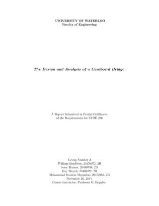
  • 1. UNIVERSITY OF WATERLOO Faculty of Engineering The Design and Analysis of a Cardboard Bridge A Report Submitted in Partial Fulfillment of the Requirements for SYDE 286 Group Number 2 William Bradbeer, 20459972, 2B Isaac Hunter, 20480938, 2B Duy Huynh, 20460022, 2B Mohammad Hossein Mayanloo, 20472285, 2B November 26, 2014. Course Instructor: Professor G. Heppler
  • 2. TABLE OF CONTENTS 1 Introduction . . . . . . . . . . . . . . . . . . . . . . . . . . . . . . . . . . . 1 2 Discussion . . . . . . . . . . . . . . . . . . . . . . . . . . . . . . . . . . . . . 2 2.1 Utilization of a Beam . . . . . . . . . . . . . . . . . . . . . . . . . . . . . . . 2 2.2 Final Design . . . . . . . . . . . . . . . . . . . . . . . . . . . . . . . . . . . . 2 2.3 Design Specifications . . . . . . . . . . . . . . . . . . . . . . . . . . . . . . . 3 2.3.1 Deck . . . . . . . . . . . . . . . . . . . . . . . . . . . . . . . . . . . . 4 2.3.2 Webs . . . . . . . . . . . . . . . . . . . . . . . . . . . . . . . . . . . . 5 2.3.3 Ribs . . . . . . . . . . . . . . . . . . . . . . . . . . . . . . . . . . . . 5 2.4 Alternative Design Considerations . . . . . . . . . . . . . . . . . . . . . . . . 6 2.4.1 I-beam . . . . . . . . . . . . . . . . . . . . . . . . . . . . . . . . . . . 6 2.4.2 Truss . . . . . . . . . . . . . . . . . . . . . . . . . . . . . . . . . . . . 6 2.4.3 Arch . . . . . . . . . . . . . . . . . . . . . . . . . . . . . . . . . . . . 7 2.4.4 Box Girder Beam . . . . . . . . . . . . . . . . . . . . . . . . . . . . . 7 3 Analysis . . . . . . . . . . . . . . . . . . . . . . . . . . . . . . . . . . . . . . 8 3.1 Calculations . . . . . . . . . . . . . . . . . . . . . . . . . . . . . . . . . . . . 8 3.2 Limitations of Analysis . . . . . . . . . . . . . . . . . . . . . . . . . . . . . . 21 3.3 Assumptions . . . . . . . . . . . . . . . . . . . . . . . . . . . . . . . . . . . . 23 4 Assembly . . . . . . . . . . . . . . . . . . . . . . . . . . . . . . . . . . . . . 25 4.1 Materials . . . . . . . . . . . . . . . . . . . . . . . . . . . . . . . . . . . . . 25 4.2 Construction of Roadbed . . . . . . . . . . . . . . . . . . . . . . . . . . . . . 26 4.3 Construction of Ribs . . . . . . . . . . . . . . . . . . . . . . . . . . . . . . . 27 4.4 Construction of Webs . . . . . . . . . . . . . . . . . . . . . . . . . . . . . . . 29 4.5 Final Bridge Construction . . . . . . . . . . . . . . . . . . . . . . . . . . . . 30 i
  • 3. 5 Conclusion . . . . . . . . . . . . . . . . . . . . . . . . . . . . . . . . . . . . 32 ii
  • 4. LIST OF FIGURES Figure 1 — Cross section of box girder beam. . . . . . . . . . . . . . . . . . . . . 2 Figure 2 — Cross section of pi-beam. . . . . . . . . . . . . . . . . . . . . . . . . . 3 Figure 3 — Illustration of final bridge design. . . . . . . . . . . . . . . . . . . . . 4 Figure 4 — Cross section of pi-beam used for analysis. . . . . . . . . . . . . . . . 8 Figure 5 — Free Body Diagram. . . . . . . . . . . . . . . . . . . . . . . . . . . . 9 Figure 6 — Plot of shear force. . . . . . . . . . . . . . . . . . . . . . . . . . . . . 10 Figure 7 — Plot of bending moment. . . . . . . . . . . . . . . . . . . . . . . . . . 11 Figure 8 — Derivative of deflection relation. . . . . . . . . . . . . . . . . . . . . . 13 Figure 9 — Deflection relation of the beam. . . . . . . . . . . . . . . . . . . . . . 14 Figure 10 — Cross section for determining the neutral axis. . . . . . . . . . . . . . 15 Figure 11 — Cross section for finding I about neutral axis. . . . . . . . . . . . . . 17 Figure 12 — Cutting plan used to divide mill board. . . . . . . . . . . . . . . . . . 25 Figure 13 — Schematics for the deck (roadbed). . . . . . . . . . . . . . . . . . . . 26 Figure 14 — Schematics for the rib components of the bridge. . . . . . . . . . . . . 27 Figure 15 — Connecting a pair of rib components. . . . . . . . . . . . . . . . . . . 28 Figure 16 — Schematics for web components of bridge. . . . . . . . . . . . . . . . 29 Figure 17 — Bottom view of deck and web combination, with the nine vertical markings indicating where the ribs would be attached. . . . . . . . . 30 Figure 18 — Isometric view of fully assembled bridge. . . . . . . . . . . . . . . . . 31 iii
  • 5. 1 Introduction The project involved the design, analysis, and assembly of a cardboard bridge to meet the requirements defined for the SYDE 286 Bridge Project. The optimal bridge was defined as one that has a maximum specific failure load and also designed to fail as close to the predicted load as possible. The specific failure load was defined by the following equation: Q = P mg (1) where P is the maximum load applied to the bridge before failure or vertical deflection of 2” and m is the mass of the bridge. Successful completion of the project involved application of course concepts as well as as- sembly skills. The course concepts used relate to the latter part of the course on beams. This builds off of concepts learned earlier in the course as well as in SYDE 181. The main objective of the bridge project is to be able to withstand an individual force over a 3” x 1.2” area. The bridge was supported by two points placed 18” from the center of the bridge on both sides. Materials were limited to a 40” x 32” x 0.060” mill board and a 227mL bottle of Weldbond white glue. 1
  • 6. 2 Discussion 2.1 Utilization of a Beam A bridge can be constructed with a variety of different designs ranging from trusses to arches and beams. For the constraints and materials given for this project however, it was determined that utilizing a beam would be the most efficient approach with regard to the use of materials and the ease of calculations. 2.2 Final Design After consideration of multiple designs (see Alternative Design Considerations), it was de- termined that a design similar to a box girder beam (Figure 1) with the two webs brought inwards towards the center of the roadbed would be the most optimal bridge to meet the design requirements. This design, as shown in Figure 2 will be henceforth known as the pi-beam. Figure 1: Cross section of box girder beam. 2
  • 7. Figure 2: Cross section of pi-beam. As documented by the project manual, the mill board has a high tensile to compressive strength ratio, as it can handle tensile forces much better than compressive forces. This is evidenced by the fact that the tensile values for elastic moduli and failure stresses for the mill board are much larger than the corresponding values of the mill board under compressive stress. A pi-beam bridge takes advantage of this tensile to compressive strength ratio by utilizing two webs as its support. The stiffness of the material is enough to negate deflection in the webs in this configuration. Further analysis of the material shall be discussed below in the calculation sections. Also, while not discussed in class, the stiffness of the material also prevents unwanted vibrations occurring to ensure the structural stability of the bridge. 2.3 Design Specifications The pi-beam bridge is constructed of three major parts, a deck (flange), two webs (sides) and nine ribs (braces). In order to sufficiently satisfy the constraints given by the project, the length of the bridge was chosen to be 38.0” to allow for 1.00” overhang from the supports. 3
  • 8. Figure 3: Illustration of final bridge design. 2.3.1 Deck The deck’s layer consisted of mill board cut to a 38.0” length and a 3.75” width. The 38.0” length was selected to meet the basic dimension requirements for the bridge span while minimizing the amount of material used. This is so that the bridge has a minimal weight and therefore a maximized Q value according to equation 1. The 3.75” width was selected to meet the minimum 3.00” width constraint and the additional width allows for a larger second moment of inertia (I). As will be seen in the calculations I is an important parameter for increasing the failure load. In order to minimize the risk of failure due to the buckling of the roadbed, an additional layer of mill board was glued to the deck. This second layer was dimensionally identical to the original deck to ensure that the two pieces of mill board were perfectly plane with each other and the forces were not distributed unevenly. Furthermore, initial calculations identified the single-decked bridges failure mode would be due to compression on the deck. An extra layer on the roadbed would increase the height of the neutral axis of the beam, 4
  • 9. allowing for more of the web to be in tension instead of compression. 2.3.2 Webs The webs were constructed using two pieces of mill board cut with a 38.0” length and 4.70” height placed 2.88” apart. Webs were determined to be 4.70” high to account for the thickness of the deck and the fold required to attach the web to the deck. Folding on the webs on the side forces a greater surface area for deck and web to attach. With the webs spaced 2.88” apart, the force distribution is wider and each web is directly under the each of the applied load’s sides. In addition, having the webs spaced 2.88” apart allows for 0.06” for the folds on the webs. The thickness of the doubled deck is 0.12” leaving 0.08” of tolerance in case of any construction error. Tolerance for the web was relatively generous in order to stay below the maximum height constraint of 5.00” for the bridge. 2.3.3 Ribs The ribs serve the function of preventing the webs from buckling horizontally. With the remaining material, there is the capability of constructing up to fourteen ribs that will form the cross section between the webs of the pi-beam. The ribs were required to span a height of 4.70” and a width of 2.82”. Nine ribs were chosen to be used in order to reduce 100 grams of weight and was an optimization decision based on the strength to weight ratio of the bridge. Tolerances of 0.06” were put in place to allow room for error during the construction of the pi-beam bridge. The width of the ribs were the most important dimension as they had the greatest effect on the amount of room the webs had to attach to the deck. If the width of each rib were inconsistent with each other, the side webs would have not be able to be glued consistently. An odd-number of ribs is required to allow for symmetry where the point of force acts as the centre of the beam with one rib placed directly underneath the applied 5
  • 10. force. Similarly ribs were placed to line up with the two rounded supports. The ribs were assumed to not have any affect on the compressive force that will act on the flange or the webs of the pi-beam. 2.4 Alternative Design Considerations Before a final design was selected, each alternative design below was carefully considered to identify the ideal design that met the constraints. 2.4.1 I-beam An I-beam was considered as an alternative design. A typical I-beam consists of one web constructed between two flanges. It was determined that a pi-beam would be preferable due to having two webs resisting the force instead of one. Given the constraints on the amount of mill board that can be used, the web would need to be thin, which is not optimal especially as only one one web is utilized in an I-beam. This is disadvantageous for the I-beam in comparison to the pi-beam design, as the pi-beam distributes the forces over two webs instead of one. The distance between the two webs is large and the pi-beam is less likely to fold over laterally due to possible asymmetric loading in comparison to an I-beam. 2.4.2 Truss A truss was considered also as an alternative design. A major issue with utilizing a truss in the scope of this project involved the number of joints that would be required to be glued together in order to successfully implement the design correctly. Minimizing the number of potential failure points by using as few pieces as possible is more practical with regards to gluing and constructing the parts together. Another negative is that the truss has a 6
  • 11. changing cross section. The complexity of calculations due to a changing cross section required to accurately predict the expected failure load may introduce multiple mathematical and theoretical errors which will carry over into the implementation of the design, making it unsuitable for the purposes of the project. 2.4.3 Arch A bridge with an arch design was rejected as it would be difficult to construct the rounded corners adequately. In addition, an arch requires a much larger height to width ratio than possible with the constraints of the project. 2.4.4 Box Girder Beam As pointed out above in the Final Design section, a box girder beam is very similar to a pi-beam bridge. A box beam bridge is constructed by two equal size flanges and two equal size webs put together in a way that resembles a rectangular prism. A negative of the box beam is that having a base required more use of mill board, and this would decrease force to weight ratio (Q). Using a pi-beam approximately saves 20% of the mill board. A more accurate analysis would be to also theoretically determine the amount of force to weight a box girder beam can handle and compare that value to the calculated theoretical value of the pi-beam (found below in the calculations section). 7
  • 12. 3 Analysis 3.1 Calculations The following cross section will be used for analysis. Figure 4: Cross section of pi-beam used for analysis. Before the failure loads can be determined the loading effects must be considered separate 8
  • 13. from the design of the bridge. This was done using the singularity method to proceed from the Free Body Diagram to internal shear, moment, and deflection through succesive integration. P(x) = F 2 < x − 1 >−1 − F 1.25 < x − 18.375 >0 + F 1.25 < x − 19.625 >0 + F 2 < x − 37 >−1 (2) Figure 5: Free Body Diagram. [Assumption 1, 2, 3] 9
  • 14. V (x) = − F 2 < x − 1 >0 + F 1.25 < x − 18.375 >1 − F 1.25 < x − 19.625 >1 − F 2 < x − 37 >0 −C1x (3) Figure 6: Plot of shear force. M(x) = F 2 < x − 1 >1 − F 2.5 < x − 18.375 >2 + F 2.5 < x − 19.625 >2 + F 2 < x − 37 >1 +C1x + C2 (4) 10
  • 15. Figure 7: Plot of bending moment. EIv (x) = F 4 < x − 1 >2 − F 7.5 < x − 18.375 >3 + F 7.5 < x − 19.625 >3 + F 4 < x − 37 >2 +C1x2 + C2x + C3 (5) EIv(x) = F 12 < x − 1 >3 − F 30 < x − 18.375 >4 + F 30 < x − 19.625 >4 + F 12 < x − 37 >3 +C1x3 + C2x2 + C3x + C4 (6) Use BC’s and internal conditions to determine C1, C2, C3, C4 11
  • 16. Both free ends: V (0) = 0 V (38) = 0 M(0) = 0 M(38) = 0 From V (0) = C1 , C1 = 0 From M(0) = C2 , C2 = 0 As the boundary conditions do not give sufficient information to solve for C3, C4, use the internal conditions at the two simple supports. EIv(1) = 0 0 = 0 − 0 + 0 + 0 + C3 + C4 ∴ C4 = −C3 EIv(37) = 0 0 = F 12 (36)3 − F 30 (18.625)4 + F 30 (17.375)4 + C3(34) + C4 36C3 = −2.92x10³ (F) C3 = − (80.96)F ∴ C4 = 80.96F In summary: C1 = 0 C2 = 0 C3 = 80.96 C4 = −80.96F These can be used to plot EIv(x) and EIv (x) 12
  • 17. Figure 8: Derivative of deflection relation. 13
  • 18. Figure 9: Deflection relation of the beam. In order to proceed, the location of the neutral axis must be determined. It must be assumed that the neutral axis lays along section 3. Therefore we let ’C’ vary between 0 and 4.64. 14
  • 19. Figure 10: Cross section for determining the neutral axis. [Assumption 4, 5, 7] The portion of the cross section undergoing compression will be labeled 1 and the portion undergoing tension will be 2. Section 1 is composed of two parts 1a (Constant centroid and Area) and 1b (centroid and area dependent on c). Section 2 has centroid and area varying with c. From this information we can use: E1Y1A1 = E2Y2A2 (7) 15
  • 20. to find the location of the neutral axis given (Y1), (Y2) is the distance from the neutral axis to the centroids of the sections. Given values and relations derived from cross section: E1 = 12183PSI E2 = 388701PSI A1a = 0.5022in2 A1b = (4.64 − c)(0.12 )in2 Y1a = 4.76 − c Y1b = (4.64 − c) 2 A2 = c(0.12 ) Y2 = C 2 [Assumption 9] The given values are substituted into equation (7) to give: −22591c2 − 12902c + 44861 = 0 (8) Solving using quadratic formula gives the roots: C1 = 1.15” , −1.72” 1.15” is selected as the neutral axis as it is within the bounds set. Next, the moment of inertia above the neutral axis (compression) and below tension will be calculated . 16
  • 21. Figure 11: Cross section for finding I about neutral axis. Given values for compression: A1 = 0.45 in2 A2 = 0.05225 in2 A3 = 0.4185 in2 Y1 = 3.60” Y2 = 3.52” Y3 = 1.74” where Y is the distance between the neutral axis and the centroids of sections. All sections are rectangular, therefore: 17
  • 22. I = bh3 12 (9) I1 = 5.4x10⁻⁴ I2 = 1.579x10⁻⁵ I3 = 0.424 Use the parallel axis theorem to determine I for top section about NA: INAC = 3 n=1 (In + Y 2 n An) (10) INAC = 8.20 in4 (11) For tension (INAT ) AT = 0.138 in2 YT = 0.576 in IT = bh3 12 = 0.0153 in4 (12) Using Parallel Axis Theorem again: INAT = IT + Y 2 T AT (13) INAT = 0.0612 in4 (14) The sum of the two moment of inertia’s can be written as follows: INA = INAT + INAC (15) 18
  • 23. INA = 8.26 in4 (16) In order to determine failure loads the weighted flexural rigidity (EI) must be calculated. EI = ET IT + ECIC (17) Given as material properties along the grain: ET = 388701 PSI EC = 12183 PSI From above, IT = 0.0612in4 IC = 8.20in4 EI = 123696.2 = 1.236 × 10⁵ Pin2 (18) The formulas for flexural stress in composite materials will be used to determine failure loads. σx1 = −ME1y EI , σx2 = −ME2y EI (19) To evaluate this expression we must determine Mmax in terms of F, the applied force. The distance X along the length at which the maximum moment occurs can be visually inspected from the M(X) plot or from the V (X) plot where V (X) = 0, M(19) = Mmax = F 2 (19 − 1) − F 2.5 (19 − 18.375)2 = F(8.843) (20) 19
  • 24. For maximum tension, YT = C = 1.15 (21) Given σT = 6120PSI Flexure formula becomes, 6120PSI = −8.843 × F × 388701 × −1.15 1.236 × 10⁵ (22) ∴ The force needed for failure due to tension is F = 191.3lbs Similarly for maximum compression, YC = 3.67 (23) Given σC = 1180PSI [Assumption 8] −1180PSI = −8.843 × F × 12183 × 3.67 1.236 × 10⁵ (24) ∴ The force needed for failure due to compression is F = 367.1lbs Given a deflection restriction of 2”, a failure load can be calculated. Minimum failure load occurs at maximum deflection. From inspection of the EIv(x) graph and its derivative EIv (X), it can be established that the maximum deflection occurs at x = 19. EIv(19) = F 12 (19 − 1)3 − F 30 (19 − 18.375)4 + 80.96 − 80.96 × 19 (25) 20
  • 25. V (19) = F EI × (−971.2) (26) Substituting in restriction and EI, 2 = F(−971.2) 1.236 × 10⁵ (27) ∴ After solving for F, the force needed for failure due to deflection is F = 254.5 lbs. Based on our restrictions, design, and material properties, we select the smallest failure load F = 191.3lbs ∴The designed bridge is failing due to tension at 191 lbs. [Assumption 6, 8, 10] 3.2 Limitations of Analysis The calculations above attempt to approximate the failure load of the designed bridge. Several simplifications were made that limit the accuracy of the results. Some of these limitations are due to an imperfect building process while the rest come from simplified physical relations. All analysis was done on the bridge as it was designed. Imperfections in the assembly would change the dimensions and introduce additional failure modes. A lack of symmetry about the X-Y plane would introduce torsion, something that has not been included in the analysis. Joints that have not properly been attached can create stress concentrations and fail at levels below the calculated value. The errors due to assembly are random and therefore difficult 21
  • 26. to account for in the analysis. Measurement of the assembled structure could be performed to reduce this, although that is not feasible for full scale models and introduces additional error. The analysis performed was focused on the cross section of the beam and its relation to the internal forces and moments. A consistent cross section was used to simplify this con- siderably. The bridge designed has an inconsistent cross section however. It is piecewise consistent over the length. The method used does not easily allow for inconsistent cross sections. Any modifications to do this are outside the scope of the course. In this way the analysis is limited to a constant cross section and assumptions must be made in order to include other designs. The analysis performed does not include analysis of failure due to shear. Given a consistent cross section, and a relationship between V(x) and F, shear flow could be calculated. How- ever, as a failure shear force was not given a failure load could not be calculated. Assumptions need to be made to dismiss this failure mode. The analysis performed does not include analysis of effects due to Poisson’s ratio. This was not done for two reasons. One, the analysis used does not allow for the simple inclusion of the Poisson effect. Second, no Poissons ratio was given. Using the analysis presented in SYDE 286 not all failure modes could be considered. The beam is considered to be rigid in all dimensions other than along X. However, there would be deflection in the webs (bowing in or out) when a vertical forces is applied. This could not be considered as a failure mode as the analysis is outside the scope of the course. Only macroscopic properties of the material could be presented using the course analysis. Failure modes due to inconsistencies in the material were not considered. 22
  • 27. 3.3 Assumptions 1. It was assumed that the mass of the bridge was negligible and not a component of the Free Body Diagram. The applied force is significantly larger than the weight of the bridge (hundreds of pounds versus less than two pounds. This was necessary as the exact weight of the bridge could not be calculated from the design. 2. It was assumed that the two round supports react point forces. This was necessary as the contact surface between the support and the bridge is dependent on analysis outside the scope of this course. This is valid assumption as the supports have a small radius relative to the length of the bridge. 3. It was assumed that the load will be placed evenly in center for all dimensions. This implies that there will be symmetry across the x-y and z-y plane. This was necessary as an error in load placement cannot be predicted. It also removes the difficulty of analyzing for torsion. 4. It was assumed that the ribs have no effect on resistance to internal forces and moments. Therefore they do not have to be included in the cross section. This was necessary due to the discontinuous nature of the ribs. No analysis of discontinuous cross section beams has been done in SYDE 286 and therefore this assumption can not be validated. 5. It was assumed that the ribs would stop all deflections of the webs in the z-direction. An inability to account for the webs buckling was a limitation requiring this assumption. The ribs were place sufficiently close together in order to validate this assumption. 6. It was assumed that the bridge would not fail due to a shear force. This implies that shear flow in all sections of the design is less than the failure stress. This was a necessary assumption as the failure stress due to shear was not given. The resistance due to shear was increased in the design through rib placement. ribs were placed to 23
  • 28. line up with the load and the two reaction forces. It is very unlikely that the bridge will shear through the rib due to the large cross section. 7. It was assumed that the glue provides no height and is a perfect seal. This assumption allows for a simple cross section without separations due to glue. It allows for treating the bridge like a bi-modulus beam and not some more complicated composite. This is a valid assumption as only a very thin layer of glue is needed to bond the mill board. Furthermore, all glued surfaces will be compressed together during construction. 8. It was assumed that the glue will not shear. This allows for discounting that as a possible failure mode. This is a valid assumption as the dried glue has is much stronger in shear than the mill board. 9. It was assumed that the material is a standard uniform homogeneous mill board. This was necessary to perform the analysis with the material properties given. Sufficient quality control of the product makes this a valid assumption. 10. It was assumed that the Poisson’s ratio of the mill board was zero. This is necessary as the Poisson effect was not included in the analysis. 24
  • 29. 4 Assembly 4.1 Materials As per the design constraints, the bridge was assembled with the limitation of using only one mill board sheet of dimensions 40” x 32” x 0.060” and a 227mL bottle of Weldbond white glue. To aid in the drafting and assembly of the bridge, a set of coloured markers, a 40” straight edge, a box cutter, and a guillotine shear were employed. To ensure that the glue was properly adhered to the bridge, the use of heavy compresses were necessary. Ideally, this would require the use of a c-clamp, but due to the limitation of materials available, binder clips and a set of textbooks were used instead. AutoCAD was utilized to generate a cutting plan for the final bridge design (Figure 12). Figure 12: Cutting plan used to divide mill board. The mill board was marked to follow the cutting plan outlined above as well as each individual 25
  • 30. part’s construction drawings. Markings following the entirety of the length of the board were aided by a 40” straight edge. For the design of this bridge, another mill board was found practical for this task. Lines that were intended to be cut were marked by solid lines, and lines intended that were to be scored for easy folding were marked by dashed lines. To ensure that the extra mill board was not mistakenly used in the final design, the unused areas were marked hatched. Afterwards, a guillotine shear was used to ensure a straight cut along the solid lines and a box cutter was lightly applied to the dashed lines to score the material. The extra mill board pieces left over were not disposed, as it could be found useful in the event a bridge component needs reinforcement. 4.2 Construction of Roadbed Figure 13: Schematics for the deck (roadbed). After the two deck components were cut out (d-01 and d-02), a moderate amount of glue was applied to the planar face of d-01. The glue was applied to the border of the deck and in an ”X” pattern in the middle to ensure that it would be highly adhesive. The second 26
  • 31. deck component d-02 was then placed symettrically on top of d-01, and binder clips were used to keep the two deck components clamped. The binder clips were connected along the outside edges of the deck with equal distances in between to ensure that the two deck pieces were compressed properly. The deck was then stowed away and left to dry for six hours. If available, a vacuum chamber would be the ideal environment for the deck to dry in order to minimize any environmental factors. 4.3 Construction of Ribs Figure 14: Schematics for the rib components of the bridge. After the rib components were cut out and scored, the individual (r-xx) were folded along the score lines by lightly applying a box-cutter. Glue was applied to the outside of the folded edges of the rib components. A rib component was paired off with another rib component, and it was ensured that the longer folding arm of one rib component (with a width of 0.5”) was attached to the longer folding arm of the other rib component. The same was repeated for the shorter folding arm (0.44”) the two rib components were attached as illustrated below in Figure 15. 27
  • 32. Figure 15: Connecting a pair of rib components. Textbooks were utilized as heavy compresses to keep the glue sealed while the rib components were drying. The ribs were left to dry for four hours. The cutting plan allowed for 14 ribs to be constructed in total. As only nine ribs were necessary for the final bridge design, each of the rib were individually inspected to ensure that the best nine ribs were selected for the bridge. Due to any errors that may have occurred during cutting or gluing the rib components, some ribs were not optimal in length or had other underlying issues and were not used in the final bridge design. However, they were not disposed of, as it may be necessary to use a substitute in case one of the ribs used in the bridge break. 28
  • 33. 4.4 Construction of Webs Figure 16: Schematics for web components of bridge. The web (w-01) as outlined in Figure 16 was folded at a 0.435” distance from the width. Glue was applied along the outside of this fold, and this flat end was connected along the length of the deck. Textbooks were pushed against the web’s outside edges (facing away from the deck) and inner edges (facing towards the deck) to maintain a 90◦ angle, and weights were used to apply pressure to the folds glued to the deck. This assembly was left to dry for six hours. 29
  • 34. 4.5 Final Bridge Construction Figure 17: Bottom view of deck and web combination, with the nine vertical markings indicating where the ribs would be attached. The double-layered deck (d-01 + d-02) and web (w-01) assembly were marked to follow the schematic in Figure 17 above. Textbooks were placed on the outside edge of the web to apply pressure in order for the web to maintain a 90◦ angle with the deck. Glue was placed on one length and width of each of the ribs, and the nine ribs were carefully positioned individually to attach onto the markings on the deck-web assembly. A compress was placed on top of each of the ribs and in front of the ribs, normal to the glue’s application, in order to keep the piece in place. This assembly was set out to dry and cure for six hours. Afterwards, the second web (w-02) was folded along the scored edge similar to the first web (w-01) in Section 4.4. Glue was applied to the outside fold of web w-02 and the exposed lengths of each of the nine ribs. The second web was carefully placed symmetrically to the first web. Compresses (textbooks) applied pressure to the outside edge of the web as well as the folded edge to help keep the glue in place. This final assembly was left to dry for six hours. 30
  • 35. The final bridge is composed of two deck pieces, two webs, and nine ribs. The bridge is assembled to appear as shown in Figure 18. Figure 18: Isometric view of fully assembled bridge. 31
  • 36. 5 Conclusion The predicted failure mode is failure due to tension with a load of 191 lbs. An actual failure load different from this can be due to multitude of reasons. As discussed in the limitations, these can arise from simplifications or assembly errors. Several assumptions were made in order for the analysis to be performed using course concepts. These limited the failure modes to internal tension, internal compression, and deflection. If the failure mode is something other than these three, then the predicted value will be meaningless. Assumptions were also made to simplify the cross section and ignore the effects of the ribs. Collectively, limitations of the analysis will produce deviations from the predicted values. 32
  • 37. References Craig, R. R., 1996. Mechanics of Materials. 3rd Edition, Danvers: John Wiley & Sons. Heppler, G. R., 2014. Design Project, University of Waterloo., Waterloo ON. 33