Downloaded 16 times


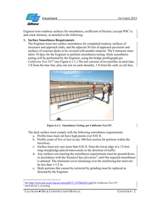
![CHAPTER 2 OCTOBER 2015
CALTRANS ● DECK CONSTRUCTION MANUAL CHAPTER 2 - 2
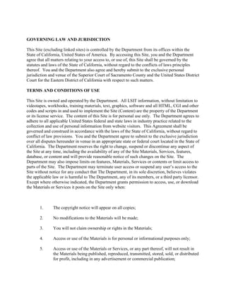
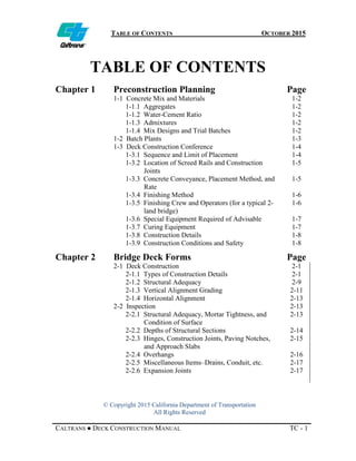
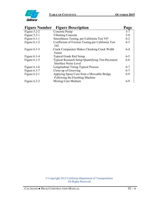
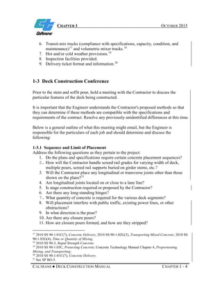
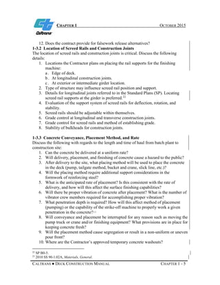
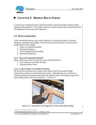
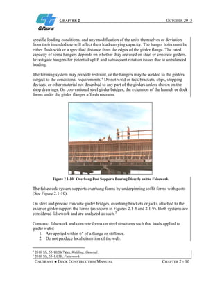
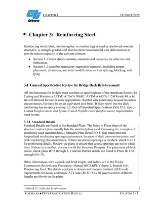
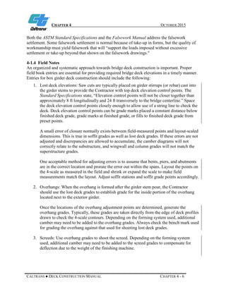
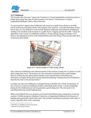
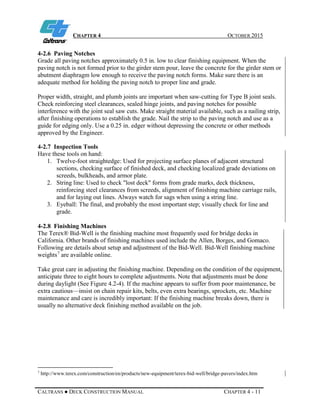
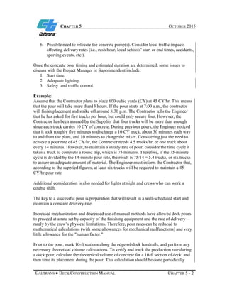
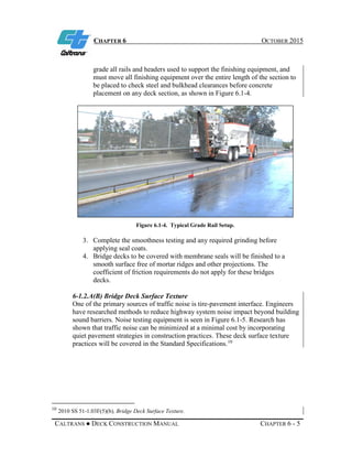
Figure 2.1-2. Typical Deck Sheathing Supports on a Concrete Box Girder Bridge.
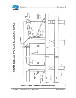
For typical cast in place structures the lost-deck forms/falsework that support the bridge
deck concrete are typically comprised of sheathing, joists, ledgers, and possibly posts.
Sheathing can be either:
• Plywood, interior or exterior grade.
• Oriented strand board.
• Other adequate board.
Sheathing should be mortar tight with all holes patched. In lieu of dutchmen patching,
metal is sometimes used to cover small holes and gaps in forms to prevent mortar leaks.
Metal and precast concrete stay-in-place forms, some having a structural significance in
the final product, have been permitted on some projects (usually detailed on the contract
plans or by Contract Change Orders [CCO]).
The sheathing sits atop the joists which are generally 4 x 4 or 2 x 4 material.
Ledgers support the joists and are typically supported by either:
• Posts.
• Rebar placed in the side of the girder stem prior to pouring, bars are generally #4,
#5 or #6.
• Low velocity powder driven nails typically used to attach wood ledgers to
concrete.
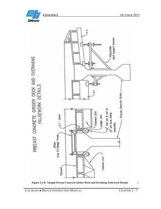
For precast or steel girder bridges it is common to see stay-in-place forms in locations
where:
• The removal of the forming would be difficult.
• Would require additional time possibly adding a season to the work.
• Cause environmental impacts.
When stay-in-place forms are proposed via a CCO, it is important to gather input from](https://image.slidesharecdn.com/bridgedeckconstructionmanual-180904184708/85/Bridge-deck-construction-manual-25-320.jpg)


The California Department of Transportation provides terms of use for its website, which includes guidelines for accessing and utilizing materials and services available on the site. Users agree to abide by these terms, and the department reserves the right to modify them at any time. The document also encompasses copyright and liability information concerning its content and external links.


