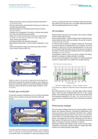
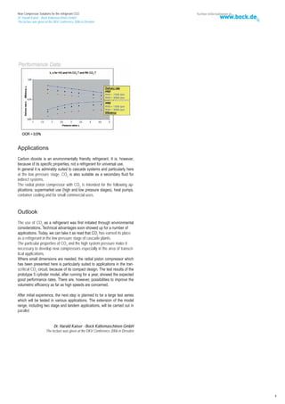
The document discusses new compressor solutions for using carbon dioxide (CO2) as a refrigerant. It describes the development of CO2 compressors including radial piston compressors. Testing shows radial piston compressors have advantages for applications requiring small size like transport refrigeration and heat pumps. The technology is promising but further testing and optimization is still needed, especially for high-speed operation.
Filing Your Delaware Franchise Tax A Detailed Guide
Bock Compressors Co2
1. New Compressor Solutions for the refrigerant CO2
Dr. Harald Kaiser - Bock Kältemaschinen GmbH
The lecture was given at the DKV Conference 2006 in Dresden
New Compressor Solutions
for the refrigerant CO2
-The regulation draft on certain fluorinated greenhouse gases, the directive
on emissions from air conditioning plants in vehicles and the change to the
directive 70/156/EWG have been accepted-
The F Gas Regulation is to limit and reduce emissions of fluorocarbons
(HFCs) from refrigeration and air conditioning plants.
The agreed legal package is an important contribution to reaching the
climate protection targets set for the EU and its member states in the
Kyoto Protocol.
Even before the F Gas Regulation came into force in July 2006, the natu-
ral refrigerant CO2 was being discussed as a possible alternative to the F
gases. Carbon dioxide is the only non flammable and virtually non toxic re-
frigerant which is also suitable for cold vapour processes in the usual range
of temperatures for today‘s refrigeration and heat pump applications.
The caloric material properties of carbon dioxide mean that when used as
a refrigerant in compression refrigeration processes there are considerably
higher pressures than were usual in refrigeration processes until now.
Advantages resulting from the high volumetric refrigeration capacity of
CO2: the compressor design volumes can be kept very compact. Low price
and ready availability also speak for using CO2.
The most promising applications for CO2 as a refrigerant are certainly heat
pump and supermarket applications as well as vehicle air conditioning. This
includes rail air conditioning as well as buses and private motor vehicles.
While there are already many examples of CO2 being used at the low pres-
sure stage of up to about 40 bar in stationary cascade plants, more recently
supermarkets, in Scandinavia especially, have been equipped with CO2 at
the high pressure stage as well.
Compressors for subcritical CO2 applications
Development of CO2 compressors
An extended finely differentiated compressor range was produced for the
The development of the transcritical CO2 compressor was started by Bock subcritical sector on the basis of the existing semi-hermetic programme.
in the early 1990s. There is therefore a complete range of semi-hermetic piston compressors
This produced the first open compressor for bus air conditioning in 1993 available for use with CO2 up to 40 bar in, for example, subcritical casca-
which was shown to the public for the first time at the IAA Utility Vehicle de systems. Adapting the compressor to CO2 is largely confined to motor
Exhibition in a Konvekta AG air conditioning plant in 1994. rating and isolated drive adjustments and corresponding modifications to
valve and seals. Naturally highest quality, quiet running and energy effici-
ency are also required of CO2 compressors.
This is based on a reliable oil supply through classical lubrication with an oil
pump independent of direction of rotation and large volume oil sump.
The drive and the valve plate have been adapted to the higher demands.
The housing material is also of a higher quality to cope with the required
higher burst pressure safety level.
Generally, the application limit diagram for CO2 is bound by two limitations:
the required size of the drive motor and the compressor discharge tempe-
rature.
Using larger drive motors, which are required because of the higher spe-
Together with leading institutes and suppliers, particularly in the valve plate cific refrigeration capacity of CO2, is limited by the space available in the
area, an optimised 2 cylinder compressor emerged in several stages. This design. Due to the isentropic exponent of CO2, discharge temperatures
compressor was then not only tested in bus air conditioning but was in are very high at very low evaporation temperatures – even if today, the
a number of national and international research projects for appropriate maximum permissible discharge temperature for CO2 is already considered
tests. to be 160°C.
Meanwhile a whole range of subctitical and transcritical piston compres-
sors had been developed.
2. New Compressor Solutions for the refrigerant CO2
Dr. Harald Kaiser - Bock Kältemaschinen GmbH
The lecture was given at the DKV Conference 2006 in Dresden
Compressors for transcritical CO2 applications
The development and design of current transcritical semi-hermetic and
open CO2 compressors was preceded by a study of the optimum construc-
tion shape.
Where the cylinders are configured in a circle, as in radial engines, the
cylinder area is within the predetermined limits. In radial motors the pistons
are moved by conrods (master rod and link rods), as opposed to radial pi-
ston compressors which run directly over eccentric pins on the drive shaft.
Numerous cylinder arrangements for optimum construction volume at good In this case the pistons are pressed outwards or restrained by suitable
suitability for CO2 high pressure range were investigated. components (slides, plates and guide rings).
Above a certain capacity level – for example from 10 m3/h – the classical
in-line or V configuration was more advantageous. Bock had already developed a radial piston compressor at the beginning of
The specific advantage of CO2 in relation to high volumetric refrigeration the 1960s which was produced as a fully hermetic version. This compres-
capacity does not, however, yet come to the forefront. The compressor sor had a special and patented mechanism to move the pistons.
displacement could be designed to be smaller (4-5 times smaller in com-
parison to compressors for F gases), but because of the necessarily higher The 4 cylinder compressors which used to be built (e.g. as automotive air
burst pressure, the compressor housing has to be more voluminous. conditioners) were nevertheless authorised up to 7000 rpm (briefly 8500
Even if the displacement is smaller for the same refrigeration capacity rpm) as compressors for R2 refrigerant.
using CO2, the required drive capacity remains the same and the coeffi-
cient of performance does not change. This means that the dimensions
of semi-hermetic CO2 compressors are determined by the required size
of the motor.
The drive can be conventionally designed with bearings, conrod and pi-
stons, but needs to be adapted to the higher pressures and loads at smaller
dimensions (e.g. piston pins).
Radial piston compressor RK6
A totally different approach was taken in designing the RK6 radial piston
compressor. In addition to specifying it to be lighter, simpler, less expen-
The newly developed RK6 radial piston compressor was the result of a
sive, the compressor was to be designed to be particularly small and com-
cooperation with Obrist Engineering GmbH, who have also been involved
pact. As explained, at a given refrigeration capacity and by assumed equal
for years in developing CO2 components.
COP, the size of the required electric motor is predetermined; for this rea-
son, the whole compressor should be within the outer diameter of the drive
The basis for the first tests was a five cylinder version. The pistons were
motor’s cylindrical envelope.
pressed outward by a five cornered eccentric ring, while a five cornered
guide ring pulled the pistons back.
1. Smaller, e.g. diameter electrical motor
2. lighter
3. simple and economically
The pistons and the „cylinder head“ are outsid this envelope in classical
in-line or V configuration.
The first prototypes were not only used for functional tests, the effective-
ness of the suction gas conduction, oil supply and heat conditions of the
compressor were also tested. These machines also served to provide the
first performance data results and were used in test plants. These colle-
cted findings led to the final compressor being a 6 cylinder version.
The description of this compressor can be summarised as follows:
2
3. New Compressor Solutions for the refrigerant CO2
Dr. Harald Kaiser - Bock Kältemaschinen GmbH
The lecture was given at the DKV Conference 2006 in Dresden
Simple overall design, layout according to the special requirements in suction is so adjusted that the motor is sufficiently cooled under all opera-
the transcritical sector. ting conditions and at the same time, a too greater discharge temperature
Only two surface seals on total compressor (housing cover, electric junc- within the extended application limits is avoided.
tion plate) (see picture below)
Spheroidal graphite cast pot-shaped closed housing for maximum
pressure resistance Oil circulation
Complete drive set integrated in the housing, no cylinder head required.
Only a few and small high pressure chambers Particular attention was given to the oil system, which contrary to tradition
Valves work on direct current principle, suction gas is pushed through at Bock manages without a pump.
the pistons in one direction and compressed. No gas change move- Numerous tests resulted in a solution being found for oil supply which gua-
ments, minimum gas pulsations. rantees reliable lubrication under any conditions. Oil carry-over is kept to a
Centrifugal lubrication with integrated oil separation very low level at the same time.
Best operating characteristics – circular 6 cylinder configuration, on one An internal double oil separator is integrated, whereby the oil conveyed
level by the suction gas flow is separated twice in the compressor. The first oil
Amply dimensioned drive motors, part suction gas cooled in two and separation is carried out in an up flow centrifugal separator. The rest of the
four pin version (1500 and 3000 /min) oil is conveyed through the machine by the suction gas and conveyed by
the rotation of the drive shaft to the lubrication points. Oil is separated by
centrifugal force at the same time.
The separated oil collects in the oil sump which is situated at the bottom,
whether the compressor is installed vertically or horizontally.
The oil carry-over rate depends on the quantity of oil, speed and pressure
conditions. It remains below 0.4 % related to the conveyed mass flow.
Totally new aspects in the spectrum of applications and development po-
tential for the compressor (for example two stage) are now available as a
result of the impressively small size, the universal installation possibilities
(standing or lying) as well as the six cylinder design arranged in a circle
on one level. The compressor is adapted to refrigeration machine oil developed specially
for CO2.
Suction gas conduction Bock C55E (produced by Fuchs) is a thermally highly resistant synthetic
ester oil, which has good miscibility/solubility with CO2. It has a special
To avoid high compression temperatures, and to not confine the application additive, which protects against wear even under the most extreme loads
limits too much, an ingenious suction gas conduction system was that compressors experience in CO2 plants. This oil has proved itself in
provided. numerous tests as a suitable lubricant for both transcritical and subcritical
plants.
Performance analysis
The most important analysis criteria are the isentropic efficiency and the
delivery rate (volumetric efficiency). Particularly the effectiveness of the
suction and pressure valves are described in the delivery rate, in addition
to the leakage and back pressure losses. The CO2 process generally works
at about three to four times lower pressure ratios, which increases the ef-
ficiency. Test readings from the very first compressors show the effect of
higher speeds in the delivery rate as well as in the efficiency (see picture
below), in comparison to previous compressors at 1500 rpm.
Optimisation potential exists relating to waste volumes and flow losses.
Compared to a conventional 2 cylinder compressor, it appears that impro-
vements can be made particularly at high speeds.
The suction gas flow is divided up by coordinated jets, so that a proportion
of the CO2 suction gas is sucked in directly. The other portion is conducted
via the electric motor. This combination of suction gas cooling and direct
3
4. New Compressor Solutions for the refrigerant CO2
Dr. Harald Kaiser - Bock Kältemaschinen GmbH
The lecture was given at the DKV Conference 2006 in Dresden
Applications
Carbon dioxide is an environmentally friendly refrigerant. It is, however,
because of its specific properties, not a refrigerant for universal use.
In general it is admirably suited to cascade systems and particularly here
at the low pressure stage. CO2 is also suitable as a secondary fluid for
indirect systems.
The radial piston compressor with CO2 is intended for the following ap-
plications: supermarket use (high and low pressure stages), heat pumps,
container cooling and for small commercial uses.
Outlook
The use of CO2 as a refrigerant was first initiated through environmental
considerations. Technical advantages soon showed up for a number of
applications. Today, we can take it as read that CO2 has earned its place
as a refrigerant in the low pressure stage of cascade plants.
The particular properties of CO2 and the high system pressure make it
necessary to develop new compressors especially in the area of transcri-
tical applications.
Where small dimensions are needed, the radial piston compressor which
has been presented here is particularly suited to applications in the tran-
scritical CO2 circuit, because of its compact design. The test results of the
prototype 5 cylinder model, after running for a year, showed the expected
good performance rates. There are, however, possibilities to improve the
volumetric efficiency as far as high speeds are concerned.
After initial experience, the next step is planned to be a large test series
which will be tested in various applications. The extension of the model
range, including two stage and tandem applications, will be carried out in
parallel.
Dr. Harald Kaiser - Bock Kältemaschinen GmbH
The lecture was given at the DKV Conference 2006 in Dresden
4