SlideShare a Scribd company logo
BALANCING USING YOUR MOBILE PHONE
By Ray Beebe
Unbalance is one of the most common causes of high vibration in machines. If the
largest vibration component in the spectra is at 1X (i.e. at the frequency
corresponding to rotation speed) then unbalance is the likely cause. Balancing is
therefore a regular maintenance activity in many workplaces. Ray Beebe explains a
method that has been successfully used on rotors large and small, with the only
instrumentation required for balancing being the stopwatch feature of a mobile
phone.
It is assumed that the severity of vibration has been assessed as unacceptable according to sources such as
the relevant part of ISO 10816 (Ref 1). Even if a machine’s vibration meets such criteria, it may be
causing annoying vibration of adjacent parts.
Looseness is another of the most common causes, and a check of foundation tightness is recommended
before proceeding to balancing. If the unbalance is due to deposition on the rotor, such as with fans
handling dirty gas, the rotor should be cleaned. In cases where a deposit is difficult or expensive to
remove, it may be expedient to balance out its effect until a more convenient time for cleaning.
The Timed Oscillation Method
This method has been used successfully for short rotors such as overhung fans up to 2m diameter, and for
pump impellers. It has also been used on smaller fans with two bearings that are nearer to what are
considered “long” rotors. The rotor must be in rolling element bearings, or set up on a mandrel and
parallel ways, and not be affected by crosswinds.
For field balancing, the usual safety precautions for opening any machine must of course be taken so that
the machine cannot be switched on while the work is in progress.
I do not know the source of the method, but I learnt it in my first job at a power station in the 1960s.
Published in Ref 2, the equation is derived from the theory of the compound pendulum.
 Mark numbers around the rotor, evenly spaced. For bladed rotors, mark at the blades.
 Choose a swing mass to fasten (by clamp or magnet) on the rotor, to give to-and-fro oscillation
time of about 20 seconds. (This gives some allowance for reaction time in operating the
stopwatch feature of your mobile phone)
 With the swing mass fixed to the rotor at Position 1, turn the rotor so that the mass is at one
horizontal position and stationary.
 Release the rotor and let it swing freely under its own inertia – do not push it in any way.
 Time the to-and-fro oscillation from the horizontal position. The left part of the sketch below
illustrates the process.
 Turn the rotor so that the mass is at the horizontal position on the other side, and repeat.
 Calculate the mean time of swing for this position, and plot on a graph of time against position
as shown in the sketch. With position numbers evenly spaced, one position appears twice - at
the start and the end of the position axis.
 Move the swing mass to Position 2, etc. and repeat the process.
 Connect the graphed points with a smooth sine wave shape, and read off the maximum and
minimum times of swing: T and t.
 Calculate the size of balance mass required from:
Balance mass = Swing mass × 22
22
tT
tT


 Make a balance mass, and fix it on the rotor at position of maximum swing time. The fixing
must of course be sufficiently strong not to allow the mass to fly off at operating speed. If
welded, allow for the mass of the weld.
o If the correction is to be made by removing mass from the rotor, remove it from the
position of minimum swing.
o If the correction mass is at a different radius to that of the swing mass, then calculate the
mass size to achieve the same moment (i.e. Mass × Radius).
 If required, verify the result by repeating the swing test for three spaced points.
Application to balance pump impellers
The method was developed and used for each impeller of a high-speed 10-stage pump of the ring-section
design (where each stage impeller is assembled in turn with its matching stationary section). We clamped
parallel ways to the bed of a milling machine. A mandrel was made to suit the impeller and a pot magnet
used as the swing magnet.
The correction was made on the adjacent milling machine using an end cutter. A table was calculated
and drawn up giving the depth of cut required in each case. The position was marked clearly on the
impeller, and it was passed to the machinist who cut the required mass from the back shroud.
The method gave satisfactory results. At the time, the only balancing machine available could only hold
the total rotor assembly, and corrections would be made on each of the end impellers. Arguably, the
impeller-by-impeller method gave a more satisfactory result.
Balancing by trial and error
Another method that may be satisfactory does not require any instrumentation. A story will illustrate the
method.
Among the cars that I have owned was a second-hand 1971 Ford Falcon (in-line 6 cylinder 4 litre
engine). It came with an after-market twin extractor exhaust system. This gave a “boy racer” burble, and
the salesman explained that it was the cause of severe vibration of the whole car that was evident at
around 90 km/h.
I tolerated this for some time before deciding that with my growing knowledge of vibration problem
solving, and fresh from solving a pump problem, I should be able to fix it. With the bonnet up, I revved
the engine, expecting to see the exhaust pipes shake about when the critical speed range was reached. To
my surprise, they did not move at all from an equilibrium position. Then I placed my hand on the
alternator and was horrified to feel it shaken off by its rough vibration! I should have figured this out
much earlier, because the alternator support bracket had been repaired by brazing, and I had replaced it
with a new one.
I removed the alternator, leaving the rotor in its end casing bearing. When spun by hand and allowed to
come to rest, it settled at the same angular position each time. So, I drilled holes in this “heavy” pole face
until the spin test showed the position at rest to vary each time.
On reassembling and back in the car, the vibration no longer occurred. This alternator must have slipped
through manufacturing QC unnoticed. (When telling this story, I usually leave out the bit about having
to ask our instrument workshop people to repair the screw thread that I had mangled just a little!)
Methods of balancing
This table outlines the several methods available.
Situation Method Equipment needed Comments
Rotor out of machine Balancing machine Balancing machine -usually done
by an external service
Refer ISO 1940/1-1986(E)
for criteria
Timed oscillation
(single plane)
Parallel ways, rotor in mandrel.
Stop watch. Swing mass (e.g. pot
magnet for small rotors).
Systematic method. Can use on short
and some longer rotors.
Trial & error (single
plane)
Parallel ways, rotor in mandrel.
Swing masses of various sizes.
Sometimes cost-effective.
Rotor in machine
("field", "in situ")
 Off-speed
Timed oscillation
Trial & error
Rotor must be in anti-friction
bearings
See above
 On-speed Single plane
(sometimes called
“static” balancing)
Vibration 1X and phase angle
measurement
For "short" rotors. 3 runs. Can do in
one shot with past history data.
Vibration measurement, no phase
angle
The “4 Runs” method (or less, with
50% chance of correct position for
balance weight). Assumes that the
vibration is predominantly 1X. (Ref
2).
Two planes (sometimes
called “dynamic
balancing”)
Vibration 1X and phase angle at
each end bearing
For "long" rotors.
4 runs using "Influence coefficients"
method. (Ref 2).
3 runs in some cases, using
"components" method where “static”
(i.e. in-phase) and “dynamic” (i.e.
anti-phase) components are treated
separately (Ref 2).
Multiple planes (but in
field on a rotor often
only two are
accessible)
Vibration and phase angles at each
end bearing
Modal balancing for flexible rotors,
rather like components method.
Computer system is usual.
Some vibration data collector/analyser devices can have capability for field balancing, using a phase
angle reference. I think that the earlier method where a vector diagram is drawn has the advantage of
visualising the process, step by step.
References
1. ISO 10816 Mechanical vibration – Evaluation of machine vibration by measurements on non-rotating parts.
(Several parts for specific machine types)
2. Beebe, Ray S Machine condition monitoring, MCM Consultants, 2009 reprint. ISBN 0646250884

More Related Content

What's hot

Well design and construction i
Well design and construction iWell design and construction i
Well design and construction i
Yalçın Dalgıç
 
Clutches
ClutchesClutches
Clutches
parth98796
 
New gseries panasonic gear motor manual
New gseries panasonic gear motor manualNew gseries panasonic gear motor manual
New gseries panasonic gear motor manual
Yan Zhang
 
Balancing of Rotating masses
Balancing of Rotating massesBalancing of Rotating masses
Balancing of Rotating masses
Rohit Singla
 
Friction clutches, brakes and dynamometer
Friction clutches, brakes and dynamometerFriction clutches, brakes and dynamometer
Friction clutches, brakes and dynamometer
ajitkarpe1986
 
2. lathe
2. lathe2. lathe
2. lathe
Prof.Mayur Modi
 
Clutch
ClutchClutch
Clutch
Navin Yadav
 
Friction in Clutch
Friction in ClutchFriction in Clutch
Friction in Clutch
Rohit Singla
 
Clutch system
Clutch systemClutch system
Clutch system
nmahi96
 

What's hot (9)

Well design and construction i
Well design and construction iWell design and construction i
Well design and construction i
 
Clutches
ClutchesClutches
Clutches
 
New gseries panasonic gear motor manual
New gseries panasonic gear motor manualNew gseries panasonic gear motor manual
New gseries panasonic gear motor manual
 
Balancing of Rotating masses
Balancing of Rotating massesBalancing of Rotating masses
Balancing of Rotating masses
 
Friction clutches, brakes and dynamometer
Friction clutches, brakes and dynamometerFriction clutches, brakes and dynamometer
Friction clutches, brakes and dynamometer
 
2. lathe
2. lathe2. lathe
2. lathe
 
Clutch
ClutchClutch
Clutch
 
Friction in Clutch
Friction in ClutchFriction in Clutch
Friction in Clutch
 
Clutch system
Clutch systemClutch system
Clutch system
 

Viewers also liked

Process diagram
Process diagramProcess diagram
Process diagram
constancamorais94
 
ICOMS2002-ABSORBER
ICOMS2002-ABSORBERICOMS2002-ABSORBER
ICOMS2002-ABSORBER
Ray Beebe
 
Sustainable Production Design Institute
Sustainable Production Design InstituteSustainable Production Design Institute
Sustainable Production Design Institute
Phoebe Hewson
 
Introduction to business
Introduction to businessIntroduction to business
Introduction to business
Qaimat Hunzai
 
Twoje smaki telebim
Twoje smaki telebimTwoje smaki telebim
Twoje smaki telebim
Marcin Gomułka
 
Pricing presentation final draft
Pricing presentation final draftPricing presentation final draft
Pricing presentation final draft
AmyH5
 
Presentation #4
Presentation #4Presentation #4
Presentation #4
constancamorais94
 
Beebe steam turbines cm apr2016 r1
Beebe steam turbines cm apr2016 r1Beebe steam turbines cm apr2016 r1
Beebe steam turbines cm apr2016 r1
Ray Beebe
 
Ch 14-Slides
Ch 14-SlidesCh 14-Slides
Ch 14-Slides
Cyrus Helf
 
Orazio vita e opere
Orazio vita e opereOrazio vita e opere
Orazio vita e opereDiana Russo
 
Создание сетки сайтов нового поколения – нюансы, про которые никто не говорит
Создание сетки сайтов нового поколения – нюансы, про которые никто не говоритСоздание сетки сайтов нового поколения – нюансы, про которые никто не говорит
Создание сетки сайтов нового поколения – нюансы, про которые никто не говорит
NaZapad
 

Viewers also liked (11)

Process diagram
Process diagramProcess diagram
Process diagram
 
ICOMS2002-ABSORBER
ICOMS2002-ABSORBERICOMS2002-ABSORBER
ICOMS2002-ABSORBER
 
Sustainable Production Design Institute
Sustainable Production Design InstituteSustainable Production Design Institute
Sustainable Production Design Institute
 
Introduction to business
Introduction to businessIntroduction to business
Introduction to business
 
Twoje smaki telebim
Twoje smaki telebimTwoje smaki telebim
Twoje smaki telebim
 
Pricing presentation final draft
Pricing presentation final draftPricing presentation final draft
Pricing presentation final draft
 
Presentation #4
Presentation #4Presentation #4
Presentation #4
 
Beebe steam turbines cm apr2016 r1
Beebe steam turbines cm apr2016 r1Beebe steam turbines cm apr2016 r1
Beebe steam turbines cm apr2016 r1
 
Ch 14-Slides
Ch 14-SlidesCh 14-Slides
Ch 14-Slides
 
Orazio vita e opere
Orazio vita e opereOrazio vita e opere
Orazio vita e opere
 
Создание сетки сайтов нового поколения – нюансы, про которые никто не говорит
Создание сетки сайтов нового поколения – нюансы, про которые никто не говоритСоздание сетки сайтов нового поколения – нюансы, про которые никто не говорит
Создание сетки сайтов нового поколения – нюансы, про которые никто не говорит
 

Similar to Beebe - Balancing by timed oscillation (AUS)

Gearbox Troubleshooting, Inspection & Maintenance.pptx
Gearbox Troubleshooting, Inspection & Maintenance.pptxGearbox Troubleshooting, Inspection & Maintenance.pptx
Gearbox Troubleshooting, Inspection & Maintenance.pptx
FahadReda2
 
highspeedbalancingofrotors-181004093658-2.PDF
highspeedbalancingofrotors-181004093658-2.PDFhighspeedbalancingofrotors-181004093658-2.PDF
highspeedbalancingofrotors-181004093658-2.PDF
Kiran252903
 
Bhel presentation
 Bhel presentation Bhel presentation
Bhel presentation
Ishant Gautam.
 
Design and development of a six tool turret using Geneva Mechanism
Design and development of a six tool turret using Geneva MechanismDesign and development of a six tool turret using Geneva Mechanism
Design and development of a six tool turret using Geneva Mechanism
Sundar Bhattacharjee
 
ODS ANALYSIS BY SALAH KHAIRY.
ODS ANALYSIS BY SALAH KHAIRY.ODS ANALYSIS BY SALAH KHAIRY.
ODS ANALYSIS BY SALAH KHAIRY.
Salah Khairy
 
jurnal (inggris)
jurnal (inggris)jurnal (inggris)
jurnal (inggris)
ekania w
 
Power generation from speedbreakers
Power generation from speedbreakersPower generation from speedbreakers
Power generation from speedbreakers
Suchit Moon
 
Power generation using speed breaker
Power generation using speed breakerPower generation using speed breaker
Power generation using speed breaker
Hitesh Sahu
 
ROBOTICS and AUTOMATION concepts of Robotics.pptx
ROBOTICS and AUTOMATION concepts of Robotics.pptxROBOTICS and AUTOMATION concepts of Robotics.pptx
ROBOTICS and AUTOMATION concepts of Robotics.pptx
srivastavavaibhav129
 
General Extruder Audit Information
General Extruder Audit InformationGeneral Extruder Audit Information
General Extruder Audit Information
R&B Plastics Machinery
 
Condition monitoring & vibration analysis
Condition monitoring & vibration analysisCondition monitoring & vibration analysis
Condition monitoring & vibration analysis
Jai Kishan
 
Powergenerationfromspeedbreakersautosaved1byjashobantibiswal 121126041930-php...
Powergenerationfromspeedbreakersautosaved1byjashobantibiswal 121126041930-php...Powergenerationfromspeedbreakersautosaved1byjashobantibiswal 121126041930-php...
Powergenerationfromspeedbreakersautosaved1byjashobantibiswal 121126041930-php...
Bikash Sahoo
 
Stepper motor
Stepper motorStepper motor
Stepper motor
SurajUdoshi
 
Field Balancing of Critical Rotating Machines
Field Balancing of Critical Rotating MachinesField Balancing of Critical Rotating Machines
Field Balancing of Critical Rotating Machines
Praveen Manocha
 
Power generation from speed breakers
Power generation from speed breakersPower generation from speed breakers
Power generation from speed breakers
Bhanu Tomar
 
B0502 01 0510
B0502 01 0510B0502 01 0510
B0502 01 0510
IJMER
 
Balance quality requirements_of_rigid_rotors
Balance quality requirements_of_rigid_rotorsBalance quality requirements_of_rigid_rotors
Balance quality requirements_of_rigid_rotors
Sarafian Salleh
 
Project Motorized Scotch Yoke Mechanism
Project Motorized Scotch Yoke MechanismProject Motorized Scotch Yoke Mechanism
Project Motorized Scotch Yoke Mechanism
NAUMAN NAEEM
 
Manual Robot workshop by Robocrazy www.onlineTPS.com
Manual Robot workshop by Robocrazy www.onlineTPS.comManual Robot workshop by Robocrazy www.onlineTPS.com
Manual Robot workshop by Robocrazy www.onlineTPS.com
Total Project Solutions
 
Report of Rotor
Report of RotorReport of Rotor

Similar to Beebe - Balancing by timed oscillation (AUS) (20)

Gearbox Troubleshooting, Inspection & Maintenance.pptx
Gearbox Troubleshooting, Inspection & Maintenance.pptxGearbox Troubleshooting, Inspection & Maintenance.pptx
Gearbox Troubleshooting, Inspection & Maintenance.pptx
 
highspeedbalancingofrotors-181004093658-2.PDF
highspeedbalancingofrotors-181004093658-2.PDFhighspeedbalancingofrotors-181004093658-2.PDF
highspeedbalancingofrotors-181004093658-2.PDF
 
Bhel presentation
 Bhel presentation Bhel presentation
Bhel presentation
 
Design and development of a six tool turret using Geneva Mechanism
Design and development of a six tool turret using Geneva MechanismDesign and development of a six tool turret using Geneva Mechanism
Design and development of a six tool turret using Geneva Mechanism
 
ODS ANALYSIS BY SALAH KHAIRY.
ODS ANALYSIS BY SALAH KHAIRY.ODS ANALYSIS BY SALAH KHAIRY.
ODS ANALYSIS BY SALAH KHAIRY.
 
jurnal (inggris)
jurnal (inggris)jurnal (inggris)
jurnal (inggris)
 
Power generation from speedbreakers
Power generation from speedbreakersPower generation from speedbreakers
Power generation from speedbreakers
 
Power generation using speed breaker
Power generation using speed breakerPower generation using speed breaker
Power generation using speed breaker
 
ROBOTICS and AUTOMATION concepts of Robotics.pptx
ROBOTICS and AUTOMATION concepts of Robotics.pptxROBOTICS and AUTOMATION concepts of Robotics.pptx
ROBOTICS and AUTOMATION concepts of Robotics.pptx
 
General Extruder Audit Information
General Extruder Audit InformationGeneral Extruder Audit Information
General Extruder Audit Information
 
Condition monitoring & vibration analysis
Condition monitoring & vibration analysisCondition monitoring & vibration analysis
Condition monitoring & vibration analysis
 
Powergenerationfromspeedbreakersautosaved1byjashobantibiswal 121126041930-php...
Powergenerationfromspeedbreakersautosaved1byjashobantibiswal 121126041930-php...Powergenerationfromspeedbreakersautosaved1byjashobantibiswal 121126041930-php...
Powergenerationfromspeedbreakersautosaved1byjashobantibiswal 121126041930-php...
 
Stepper motor
Stepper motorStepper motor
Stepper motor
 
Field Balancing of Critical Rotating Machines
Field Balancing of Critical Rotating MachinesField Balancing of Critical Rotating Machines
Field Balancing of Critical Rotating Machines
 
Power generation from speed breakers
Power generation from speed breakersPower generation from speed breakers
Power generation from speed breakers
 
B0502 01 0510
B0502 01 0510B0502 01 0510
B0502 01 0510
 
Balance quality requirements_of_rigid_rotors
Balance quality requirements_of_rigid_rotorsBalance quality requirements_of_rigid_rotors
Balance quality requirements_of_rigid_rotors
 
Project Motorized Scotch Yoke Mechanism
Project Motorized Scotch Yoke MechanismProject Motorized Scotch Yoke Mechanism
Project Motorized Scotch Yoke Mechanism
 
Manual Robot workshop by Robocrazy www.onlineTPS.com
Manual Robot workshop by Robocrazy www.onlineTPS.comManual Robot workshop by Robocrazy www.onlineTPS.com
Manual Robot workshop by Robocrazy www.onlineTPS.com
 
Report of Rotor
Report of RotorReport of Rotor
Report of Rotor
 

More from Ray Beebe

W2 deposits 1977
W2 deposits 1977W2 deposits 1977
W2 deposits 1977
Ray Beebe
 
Structural vibration absorber PPt
Structural vibration absorber PPtStructural vibration absorber PPt
Structural vibration absorber PPt
Ray Beebe
 
My biggest success in balancing a fan was a few years ago
My biggest success in balancing a fan was a few years agoMy biggest success in balancing a fan was a few years ago
My biggest success in balancing a fan was a few years ago
Ray Beebe
 
Ray Mar2015 5 big CM wins
Ray Mar2015 5 big CM winsRay Mar2015 5 big CM wins
Ray Mar2015 5 big CM wins
Ray Beebe
 
Ray's 5 Big CM Wins
Ray's 5 Big CM Wins Ray's 5 Big CM Wins
Ray's 5 Big CM Wins
Ray Beebe
 
Getting started with condition monitoring for only $2000
Getting started with condition monitoring for only $2000Getting started with condition monitoring for only $2000
Getting started with condition monitoring for only $2000
Ray Beebe
 
Study & career paths for Maintenance people (Ray Beebe)
Study & career paths for Maintenance people (Ray Beebe)Study & career paths for Maintenance people (Ray Beebe)
Study & career paths for Maintenance people (Ray Beebe)
Ray Beebe
 
Optimum overhaul of pumps 2014
Optimum overhaul of pumps 2014Optimum overhaul of pumps 2014
Optimum overhaul of pumps 2014
Ray Beebe
 
Condition monitoring of steam turbines
Condition monitoring of steam turbinesCondition monitoring of steam turbines
Condition monitoring of steam turbines
Ray Beebe
 
45 years in cm (slide share2013)
45 years in cm  (slide share2013)45 years in cm  (slide share2013)
45 years in cm (slide share2013)
Ray Beebe
 

More from Ray Beebe (10)

W2 deposits 1977
W2 deposits 1977W2 deposits 1977
W2 deposits 1977
 
Structural vibration absorber PPt
Structural vibration absorber PPtStructural vibration absorber PPt
Structural vibration absorber PPt
 
My biggest success in balancing a fan was a few years ago
My biggest success in balancing a fan was a few years agoMy biggest success in balancing a fan was a few years ago
My biggest success in balancing a fan was a few years ago
 
Ray Mar2015 5 big CM wins
Ray Mar2015 5 big CM winsRay Mar2015 5 big CM wins
Ray Mar2015 5 big CM wins
 
Ray's 5 Big CM Wins
Ray's 5 Big CM Wins Ray's 5 Big CM Wins
Ray's 5 Big CM Wins
 
Getting started with condition monitoring for only $2000
Getting started with condition monitoring for only $2000Getting started with condition monitoring for only $2000
Getting started with condition monitoring for only $2000
 
Study & career paths for Maintenance people (Ray Beebe)
Study & career paths for Maintenance people (Ray Beebe)Study & career paths for Maintenance people (Ray Beebe)
Study & career paths for Maintenance people (Ray Beebe)
 
Optimum overhaul of pumps 2014
Optimum overhaul of pumps 2014Optimum overhaul of pumps 2014
Optimum overhaul of pumps 2014
 
Condition monitoring of steam turbines
Condition monitoring of steam turbinesCondition monitoring of steam turbines
Condition monitoring of steam turbines
 
45 years in cm (slide share2013)
45 years in cm  (slide share2013)45 years in cm  (slide share2013)
45 years in cm (slide share2013)
 

Beebe - Balancing by timed oscillation (AUS)

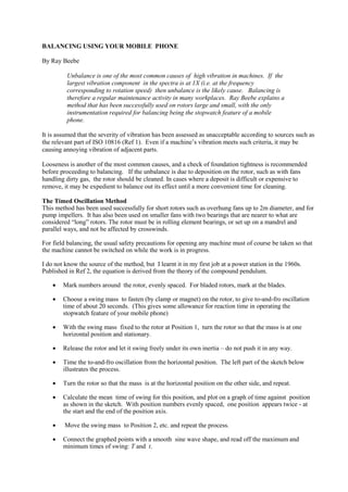
  • 1. BALANCING USING YOUR MOBILE PHONE By Ray Beebe Unbalance is one of the most common causes of high vibration in machines. If the largest vibration component in the spectra is at 1X (i.e. at the frequency corresponding to rotation speed) then unbalance is the likely cause. Balancing is therefore a regular maintenance activity in many workplaces. Ray Beebe explains a method that has been successfully used on rotors large and small, with the only instrumentation required for balancing being the stopwatch feature of a mobile phone. It is assumed that the severity of vibration has been assessed as unacceptable according to sources such as the relevant part of ISO 10816 (Ref 1). Even if a machine’s vibration meets such criteria, it may be causing annoying vibration of adjacent parts. Looseness is another of the most common causes, and a check of foundation tightness is recommended before proceeding to balancing. If the unbalance is due to deposition on the rotor, such as with fans handling dirty gas, the rotor should be cleaned. In cases where a deposit is difficult or expensive to remove, it may be expedient to balance out its effect until a more convenient time for cleaning. The Timed Oscillation Method This method has been used successfully for short rotors such as overhung fans up to 2m diameter, and for pump impellers. It has also been used on smaller fans with two bearings that are nearer to what are considered “long” rotors. The rotor must be in rolling element bearings, or set up on a mandrel and parallel ways, and not be affected by crosswinds. For field balancing, the usual safety precautions for opening any machine must of course be taken so that the machine cannot be switched on while the work is in progress. I do not know the source of the method, but I learnt it in my first job at a power station in the 1960s. Published in Ref 2, the equation is derived from the theory of the compound pendulum.  Mark numbers around the rotor, evenly spaced. For bladed rotors, mark at the blades.  Choose a swing mass to fasten (by clamp or magnet) on the rotor, to give to-and-fro oscillation time of about 20 seconds. (This gives some allowance for reaction time in operating the stopwatch feature of your mobile phone)  With the swing mass fixed to the rotor at Position 1, turn the rotor so that the mass is at one horizontal position and stationary.  Release the rotor and let it swing freely under its own inertia – do not push it in any way.  Time the to-and-fro oscillation from the horizontal position. The left part of the sketch below illustrates the process.  Turn the rotor so that the mass is at the horizontal position on the other side, and repeat.  Calculate the mean time of swing for this position, and plot on a graph of time against position as shown in the sketch. With position numbers evenly spaced, one position appears twice - at the start and the end of the position axis.  Move the swing mass to Position 2, etc. and repeat the process.  Connect the graphed points with a smooth sine wave shape, and read off the maximum and minimum times of swing: T and t.
  • 2.  Calculate the size of balance mass required from: Balance mass = Swing mass × 22 22 tT tT    Make a balance mass, and fix it on the rotor at position of maximum swing time. The fixing must of course be sufficiently strong not to allow the mass to fly off at operating speed. If welded, allow for the mass of the weld. o If the correction is to be made by removing mass from the rotor, remove it from the position of minimum swing. o If the correction mass is at a different radius to that of the swing mass, then calculate the mass size to achieve the same moment (i.e. Mass × Radius).  If required, verify the result by repeating the swing test for three spaced points. Application to balance pump impellers The method was developed and used for each impeller of a high-speed 10-stage pump of the ring-section design (where each stage impeller is assembled in turn with its matching stationary section). We clamped parallel ways to the bed of a milling machine. A mandrel was made to suit the impeller and a pot magnet used as the swing magnet. The correction was made on the adjacent milling machine using an end cutter. A table was calculated and drawn up giving the depth of cut required in each case. The position was marked clearly on the impeller, and it was passed to the machinist who cut the required mass from the back shroud. The method gave satisfactory results. At the time, the only balancing machine available could only hold the total rotor assembly, and corrections would be made on each of the end impellers. Arguably, the impeller-by-impeller method gave a more satisfactory result. Balancing by trial and error Another method that may be satisfactory does not require any instrumentation. A story will illustrate the method. Among the cars that I have owned was a second-hand 1971 Ford Falcon (in-line 6 cylinder 4 litre engine). It came with an after-market twin extractor exhaust system. This gave a “boy racer” burble, and the salesman explained that it was the cause of severe vibration of the whole car that was evident at around 90 km/h. I tolerated this for some time before deciding that with my growing knowledge of vibration problem solving, and fresh from solving a pump problem, I should be able to fix it. With the bonnet up, I revved the engine, expecting to see the exhaust pipes shake about when the critical speed range was reached. To
  • 3. my surprise, they did not move at all from an equilibrium position. Then I placed my hand on the alternator and was horrified to feel it shaken off by its rough vibration! I should have figured this out much earlier, because the alternator support bracket had been repaired by brazing, and I had replaced it with a new one. I removed the alternator, leaving the rotor in its end casing bearing. When spun by hand and allowed to come to rest, it settled at the same angular position each time. So, I drilled holes in this “heavy” pole face until the spin test showed the position at rest to vary each time. On reassembling and back in the car, the vibration no longer occurred. This alternator must have slipped through manufacturing QC unnoticed. (When telling this story, I usually leave out the bit about having to ask our instrument workshop people to repair the screw thread that I had mangled just a little!) Methods of balancing This table outlines the several methods available. Situation Method Equipment needed Comments Rotor out of machine Balancing machine Balancing machine -usually done by an external service Refer ISO 1940/1-1986(E) for criteria Timed oscillation (single plane) Parallel ways, rotor in mandrel. Stop watch. Swing mass (e.g. pot magnet for small rotors). Systematic method. Can use on short and some longer rotors. Trial & error (single plane) Parallel ways, rotor in mandrel. Swing masses of various sizes. Sometimes cost-effective. Rotor in machine ("field", "in situ")  Off-speed Timed oscillation Trial & error Rotor must be in anti-friction bearings See above  On-speed Single plane (sometimes called “static” balancing) Vibration 1X and phase angle measurement For "short" rotors. 3 runs. Can do in one shot with past history data. Vibration measurement, no phase angle The “4 Runs” method (or less, with 50% chance of correct position for balance weight). Assumes that the vibration is predominantly 1X. (Ref 2). Two planes (sometimes called “dynamic balancing”) Vibration 1X and phase angle at each end bearing For "long" rotors. 4 runs using "Influence coefficients" method. (Ref 2). 3 runs in some cases, using "components" method where “static” (i.e. in-phase) and “dynamic” (i.e. anti-phase) components are treated separately (Ref 2). Multiple planes (but in field on a rotor often only two are accessible) Vibration and phase angles at each end bearing Modal balancing for flexible rotors, rather like components method. Computer system is usual. Some vibration data collector/analyser devices can have capability for field balancing, using a phase angle reference. I think that the earlier method where a vector diagram is drawn has the advantage of visualising the process, step by step. References 1. ISO 10816 Mechanical vibration – Evaluation of machine vibration by measurements on non-rotating parts. (Several parts for specific machine types) 2. Beebe, Ray S Machine condition monitoring, MCM Consultants, 2009 reprint. ISBN 0646250884