
Recommended
Recommended
More Related Content
Similar to Basics of Disater And its Management.pdf
Similar to Basics of Disater And its Management.pdf (20)
Recently uploaded
Recently uploaded (20)
Basics of Disater And its Management.pdf
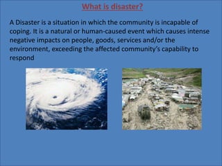
- 1. What is disaster? A Disaster is a situation in which the community is incapable of coping. It is a natural or human-caused event which causes intense negative impacts on people, goods, services and/or the environment, exceeding the affected community’s capability to respond
- 2. What is disaster management? Disaster management can be defined as the discipline and profession of applying science, technology, planning and management to deal with extreme events. The emphasis of disaster management is prevention and loss reduction Disaster management activity is divided into the following phases as Planning Mitigation Preparedness Response Recovery
- 3. ROLES THAT REMOTE SENSING AND GIS PLAY IN DISASTER MANAGEMENT PHRRASES Planning • GIS is useful in helping with forward planning. • It provides the framework for planners and disaster managers to view spatial data by way of computer based maps. Mitigation •Representation of High risk areas •Facilitates the implementation of necessary mechanism to lessen the impact. Preparedness •Identification of emergency areas •Positions of related departments, Agencies, and Human Resources •Make it easier for security and shelters provides to plan the strategies Response •Provide accurate information on exact location of an emergency situation •Time saving during the determination of trouble areas (Quick Response) •Used as floor guide for evacuation routes
- 4. Recovery Mapping level of damage Information related to disrupted infrastructure, number of persons died or injured and impact on Environment. GIS and data gathering- The data required for disaster management is coming from different scientific disciplines, and should be integrated Data integration is one of the strongest points of GIS. In general the following types of data are required: • Data on the disastrous phenomena (e.g. landslides, floods, earthquakes), their location, frequency, magnitude etc. • Data on the environment in which the disastrous events might take place: topography, geology, geo-morphology, soils, hydrology, land use, vegetation etc. • Data on the elements that might be destroyed if the event takes place: infrastructure, settlements , population, socio-economic data
- 5. Role of remote sensing in CYCLONE- MITIGATION PREPAREDNESS RESCUE RECOVERY SATELLITES USED: Risk modelling; vulnerability analysis. Early warning; long-range climate modelling Identifying escape routes; crisis mapping; impact assessment; cyclone monitoring; storm surge predictions. Damage assessment; spatial planning. KALPANA-1; INSAT-3A; QuikScat radar; Meteosat Fig: Movement of cyclone
- 6. . Through these pictures one can estimate the storm's position, direction and speed, maximum wind speeds, areas likely to be affected, and likely storm surges. The programme issues these to government officials, river port authorities, the general public, coast guard, non-governmental organisations and cyclone preparedness programmes across the world
- 7. CASE STUDY ON PHALIN CYCLONE- 7th oct,2013 8th oct,2013 10th oct,2013 12th oct,2013
- 8. 7th October, 2013: Indian Meteorological Department received information from KALPANA I, OCEANSAT and INSAT 3A Doppler radars deployed at vulnerable places, with over-lap, sensors in the sea and through the ships, about a cyclone forming in the gulf between Andaman Nicobar and Thailand named PHAILIN (Thai for “Sapphire”). 8th October, 2013: IMD confirmed cyclone formation and predicted it as “severe cyclone” and its effects would be felt from Kalingapatnam in Andhra Pradesh to Paradeep in Odisha, and that it would probably first strikethe port of Gopalpur in Ganjam district at about 5 pm on 12 October. The wind speed could touch 200(km/h). 10th October, 2013: IMD prediction of a severe cyclone was converted to a “very severe cyclonic storm” with wind speeds up to 220 kmph. the US Navy’s Joint Typhoon Warning Centre predicted it would have wind speeds up to 315 km/h. 12th October, 2013: The “very severe” cyclonic storm had its landfall at Gopalpur port at about 9 pm with a wind speed of 200 km/h.
- 9. MITIGATION PREPAREDNESS RESPONSE RECOVERY GIS: Risk modelling; vulnerability analysis; Strengthening EWS; Disaster Response Infrastructures; Disaster Drills Early Warning System; Constant updates from ISRO, IMD and USNJTWC etc.; Distribution of Satellite Phones , VHF and HAMRADIO to DMs, BDO’s, Sarpanch etc.; Mass Evacuation on the basis of cyclone’s path over the state. Google Crisis Map; Google People Finder; ODRAF & NDRF Deployment; Relief Operations coordinated by Navy & Air Force; Disaster Assessment; Logistics Coordinated by Centrally Operated Units; Spatial planning;
- 10. MITIGATION PREPAREDNESS RESCUE RECOVERY SATELLITES USED Mapping flood-prone areas; delineating flood- plains; land-use mapping. Flood detection; early warning; rainfall mapping. Flood mapping; evacuation planning; damage assessment. Damage assessment; spatial planning. Tropical Rainfall Monitoring Mission; AMSR-E; KALPANA I; Role of GIS in floods
- 12. CASE STUDY TITLE: GIS-based disaster management, A case study for Allahabad Sadar sub-district(India) by S.H. Abbas, R.K. Srivastava and R.P. Tiwari ( 2009) JOURNAL:Management of Environmental Quality: An International Journal,2009 OBJECTIVE To demonstrate a Geographic Information System (GIS)-based study on development of District Disaster Management System for floods for Allahabad Sadar Sub-District(India)
- 13. STUDY AREA The study area is Sadar, sub-district of Allahabad (India) which is surrounded by river Ganga and Yamuna located between 81º 45ʹ to 82º latitude and 25º 15ʹ to 25º 30ʹ longitude METHODOLOGY •An approach has been designed to explore the scope for the combination of Disaster Management and GIS. •The flood-prone areas have been identified and their positions are marked using Arc View. • GIS has been exploited to obtain the spatial information for the effective Disaster Management for flood-affected areas
- 14. Fig: Map showing Ganga and Yamuna river around the study area
- 15. GIS-based maps for Disaster Management Various maps were generated for the analysis in the GIS platform like- • Flood-affected areas of Sadar sub-district • Population density distribution in flood prone areas • Villages having road connectivity ,hospital facility in flood affected areas • Route map for the disaster prone area
- 16. and Yamuna river both Fig: Map showing areas affected by flood by Ganga and Yamuna river
- 17. • If any government agency or any non-governmental organization wants to provide any type of help to the affected people, they can follow above generated map for having idea about the requirement. •Village administrator can monitor all flood management operations using GIS data base Fig: Map showing road connectivity
- 18. • Previous shows the road network of villages that are more vulnerable and are not been connected by main road as well as metal road. •The villages that are not having transport connectivity can be identified. •With the help of above information, one can provide rescue first to those villages not connected through metal road and after that provide transportation to metal road connected villages.
- 19. SUMMARY- • It shows that in that sub-district Sadar of Allahabad 54 villages are affected by flood when high flood level reaches up to 84.50 meters. • The GIS generated map shows that out of 54 villages only seven villages have mud road and 47 villages have paved road. •Thus, GIS tool can be beneficial for getting all the relevant information at the time of occurrence of the disaster, and can help in planning and management.
- 20. NDVI (is calculated from the visible and near-infrared light reflected by vegetation . Healthy vegetation absorbs most of the visible light that hits it, and reflects a large portion of the near-infrared light. Unhealthy or sparse vegetation reflects more visible light and less near-infrared light Role of GIS in Drought DISASTER MITIGATION PREPAREDNESS RECOVERY RESCUE SATELLITES USED DROUGHT Risk modelling; vulnerability analysis; land and water management planning. Weather forecasting; vegetation monitoring; crop water requirement mapping; early warning. Monitoring vegetation; damage assessment. Informing drought mitigation. FEWS NET; AVHRR; MODIS; SPOT
- 21. Calculations of NDVI for a given pixel always result in a number that ranges from minus one (-1) to plus one (+1); however, no green leaves gives a value close to zero. A zero means no vegetation and close to +1 (0.8 - 0.9) indicates the highest possible density of green leaves. NDVI= (NIR+RED)/(NIR-RED) where: NIR= reflectance in near infrared band RED= reflectance in red band
- 22. Fig: Pictures showing difference between densely vegetation area and drought areas
- 23. ROLE OF Remote sensing in earthquake- MITIGATION PREPAREDNESS RESCUE RECOVERY SATELLITES USED Building stock assessment; hazard mapping. Measuring strain accumulation. Planning routes for search and rescue; damage assessment; evacuation planning; deformation mapping. Damage assessment; identifying sites for rehabilitation. PALSAR; IKONOS 2; InSAR; SPOT; IRS
- 25. Picture showing predicted Tsunami wave amplitude Picture showing collapsed building