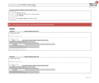
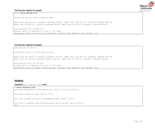
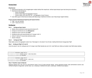
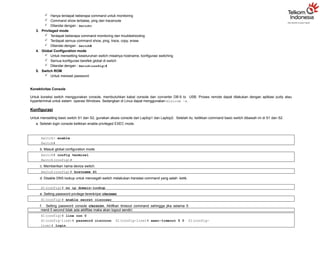
Lab 15. BasicSwitch Configuration
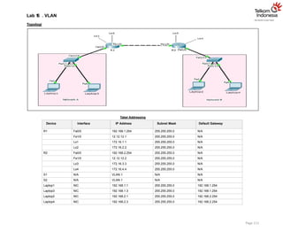
Topologi
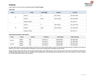
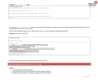
Tabel Addressing
Device Interface IP Address Subnet Mask Default Gateway
R1 Fa0/0 192.168.1.254 255.255.255.0 N/A
Fa1/0 12.12.12.1 255.255.255.0 N/A
R2 Fa0/0 192.168.2.254 255.255.255.0 N/A
Fa1/0 12.12.12.2 255.255.255.0 N/A
S1 VLAN 1 192.168.1.11 255.255.255.0 192.168.1.254
S2 N/A VLAN 1 N/A N/A
Laptop1 NIC 192.168.1.1 255.255.255.0 192.168.1.254
Laptop2 NIC 192.168.2.1 255.255.255.0 192.168.2.254
Tujuan
Setting basic switch
Konsep Dasar
Switch memiliki 5 mode :
1. Setup mode
Switch masuk setup mode jika NVRAM kosong alias tidak memiliki konfigurasi. Biasanya kondisi ini terjadi ketika kita mengaktifkan switch baru atau setelah
melakukan reset konfigurasi.
2. User mode
3.
Hanya terdapatbeberapa command untuk monitoring
Command show terbatas, ping dan traceroute
Ditandai dengan : Switch>
3. Privileged mode
Terdapat beberapa command monitoring dan troubleshooting
Terdapat semua command show, ping, trace, copy, erase
Ditandai dengan : Switch#
4. Global Configuration mode
Untuk mensetting keseluruhan switch misalnya hostname, konfigurasi switching
Semua konfigurasi berefek global di switch
Ditandai dengan : Switch(config)#
5. Switch ROM
Untuk mereset password
Konektivitas Console
Untuk koneksi switch menggunakan console, membutuhkan kabel console dan converter DB-9 to USB. Proses remote dapat dilakukan dengan aplikasi putty atau
hyperterminal untuk sistem operasi Windows. Sedangkan di Linux dapat menggunakan minicom –s.
Konfigurasi
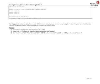
Untuk mensetting basic switch S1 dan S2, gunakan akses console dari Laptop1 dan Laptop2. Setelah itu, ketikkan command basic switch dibawah ini di S1 dan S2.
a. Setelah login console ketikkan enable privileged EXEC mode.
Switch> enable
Switch#
b. Masuk global configuration mode.
Switch# config terminal
Switch(config)#
c. Memberikan nama device switch.
Switch(config)# hostname S1
d. Disable DNS lookup untuk mencegah switch melakukan translasi command yang salah ketik.
S1(config)# no ip domain-lookup
e. Setting password privilege terenkripsi ciscosec
S1(config)# enable secret ciscosec
f. Setting password console ciscocon. Aktifkan timeout command sehingga jika selama 5
menit 0 second tidak ada aktifitas maka akan logout sendiri.
S1(config)# line con 0
S1(config-line)# password ciscocon S1(config-line)# exec-timeout 5 0 S1(config-
line)# login
4.
g. Setting passwordvty ciscovty. Aktifkan timeout command sehingga jika selama 5 menit 0 second tidak ada aktifitas maka akan logout sendiri.
S1(config)# line vty 0 4
S1(config-line)# password ciscovty S1(config-line)# exec-timeout 5 0 S1(config-
line)# login
h. Enable enkripsi clear text passwords.
S1(config)# service password-encryption
i. Buat banner yang memberikan informasi kepada user yang tidak memiliki otorisasi dilarang login switch.
S1(config)# banner motd #Unauthorized access is strictly prohibited!#
j. Setting IP address dan interface description. Aktifkan interface vlan 1 dengan sub-command
no-shutdown.
S1(config)# int vlan 1
S1(config-if)# description Connection to VLAN 1 S1(config-if)# ip address 192.168.1.11 255.255.255.0
S1(config-if)# no shutdown
S1(config-if)# exit
S1(config)# exit
S1#
k. Setting default gateway
S1(config)# ip default-gateway 192.168.1.254
l. Simpan konfigurasi file running-configuration ke startup-configuration.
S1# copy running-config startup-config
Destination filename [startup-config]? Building configuration...
[OK] S1#
Ketika kita mensetting switch, maka konfigurasi akan disimpan sementara di file running- configuration (RAM), oleh karena itu proses menyimpan penting
untuk dilakukan agar saat switch reboot atau shutdown file konfigurasi switch masih tetap disimpan di startup- configuration (NVRAM). Cara lain
menyimpan konfigurasi yaitu menggunakan command write memory atau wr mem.
Note: ulangi langkah yang sama untuk mensetting basic switch S2.
5.
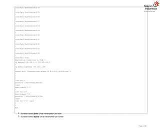
Verifikasi
Setelah mensetting basicswitch S1 dan S2, langkah selanjutnya melakukan verifikasi bahwa konfigurasi yang sudah kita setting benar.
Menampilkan informasi full konfigurasi switch
S1#show run
Building configuration...
Current configuration : 1285 bytes
!
version 12.1
no service timestamps log datetime msec no service timestamps debug datetime msec service
password-encryption
!
hostname S1
!
enable secret 5 $1$mERr$thF1sEHJ9Dl2J3WzXxyZ1/
!
no ip domain-lookup
!
!
spanning-tree mode pvst
!
interface FastEthernet0/1
!
interface FastEthernet0/2
!
interface FastEthernet0/3
!
interface FastEthernet0/4
!
interface FastEthernet0/5
!
interface FastEthernet0/6
!
interface FastEthernet0/7
!
interface FastEthernet0/8
!
interface FastEthernet0/9
!
interface FastEthernet0/10
!
interface FastEthernet0/11
!
interface FastEthernet0/12
!
interface FastEthernet0/13
!
Page 107
6.
interface FastEthernet0/14
!
interface FastEthernet0/15
!
interfaceFastEthernet0/16
!
interface FastEthernet0/17
!
interface FastEthernet0/18
!
interface FastEthernet0/19
!
interface FastEthernet0/20
!
interface FastEthernet0/21
!
interface FastEthernet0/22
!
interface FastEthernet0/23
!
interface FastEthernet0/24
!
interface Vlan1
description Connection to VLAN 1
ip address 192.168.1.11 255.255.255.0
!
ip default-gateway 192.168.1.254
!
banner motd ^CUnauthorized access is strictly prohibited!^C
!
!
!
line con 0
password 7 0822455D0A1606181C
login
exec-timeout 5 0
!
line vty 0 4
exec-timeout 5 0
password 7 0822455D0A1613030B
login
line vty 5 15 login
!
!
end
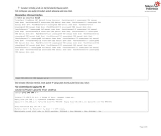
Gunakan tombol Enter untuk menampilkan per baris
Gunakan tombol Space untuk menampilkan per screen
Page 108
7.
Gunakan tombolq untuk exit dari tampilan konfigurasi switch
Cek konfigurasi yang sudah diinputkan apakah ada yang salah atau tidak.
Menampilkan informasi interface
S1#show ip interface brief
Interface IP-Address OK? Method Status Protocol FastEthernet0/1 unassigned YES manual
down down FastEthernet0/2 unassigned YES manual down down FastEthernet0/3 unassigned YES
manual down down FastEthernet0/4 unassigned YES manual down down FastEthernet0/5
unassigned YES manual down down FastEthernet0/6 unassigned YES manual down down
FastEthernet0/7 unassigned YES manual down down FastEthernet0/8 unassigned YES manual
down down FastEthernet0/9 unassigned YES manual down down FastEthernet0/10 unassigned
YES manual down down FastEthernet0/11 unassigned YES manual down down FastEthernet0/12
unassigned YES manual down down FastEthernet0/13 unassigned YES manual down down
FastEthernet0/14 unassigned YES manual down down FastEthernet0/15 unassigned YES manual
down down FastEthernet0/16 unassigned YES manual down down FastEthernet0/17 unassigned
YES manual down down FastEthernet0/18 unassigned YES manual down down FastEthernet0/19
unassigned YES manual down down FastEthernet0/20 unassigned YES manual down down
FastEthernet0/21 unassigned YES manual down down FastEthernet0/22 unassigned YES manual
down down FastEthernet0/23 unassigned YES manual down down FastEthernet0/24 unassigned
YES manual down down
Page 109
Vlan1 192.168.1.11 YES manual up up
Dari tampilan informasi interface, dicek apakah IP yang sudah diconfig sudah benar atau belum.
Tes konektivitas dari Laptop1 ke S1
Lakukan tes Ping dari Laptop1 ke S1 dan sebaliknya.
Laptop1>ping 192.168.1.11
Pinging 192.168.1.11 with 32 bytes of data: Request timed out.
Reply from 192.168.1.11: bytes=32 time=0ms TTL=255
Reply from 192.168.1.11: bytes=32 time=0ms TTL=255 Reply from 192.168.1.11: bytes=32 time=0ms TTL=255
Ping statistics for 192.168.1.11:
Packets: Sent = 4, Received = 3, Lost = 1 (25% loss),
Approximate round trip times in milli-seconds: Minimum = 0ms, Maximum = 0ms, Average = 0ms
8.
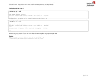
Dari output diatas,reply pertama diawal timed out kemudian dilanjutkan reply dari IP VLAN 1 S1.
Tes konektivitas dari S1 ke R1
Page 110
S1#ping 192.168.1.254
Type escape sequence to abort.
Sending 5, 100-byte ICMP Echos to 192.168.1.254, timeout is 2 seconds:
.!!!!
Success rate is 80 percent (4/5), round-trip min/avg/max = 0/0/0 ms
S1#ping 192.168.1.254
Type escape sequence to abort.
Sending 5, 100-byte ICMP Echos to 192.168.1.254, timeout is 2 seconds:
!!!!!
Success rate is 100 percent (5/5), round-trip min/avg/max = 0/0/1 ms
S1#
Dari hasil ping yang pertama success rate masih 80%, kemudian dilanjutkan yang kedua menjadi 100%.
Review
1. Secara default, apa bedanya status interface antara Switch dan Router?
Tujuan
Setting VLAN
KonsepDasar
VLAN
Membagi single broadcast domain menjadi beberapa broadcast domain
Security layer 2
Secara default semua port switch masuk VLAN 1
VLAN 1 dikenal juga sebagai Administrative VLAN atau Management VLAN
VLAN bisa dibuat dari nomor 2 – 1001
VLAN hanya bisa dikonfigurasi pada Manageable Switch saja
2 tipe VLAN :
o Static VLAN
o Dynamic VLAN
VLAN meningkatkan security network
VLAN meningkatkan jumlah broadcast domain dan menurunkan size broadcast domain
Static VLAN
Static VLAN berdasarkan port
Dilakukan secara manual untuk assign port ke VLAN
Disebut juga sebagai Port-Based VLAN
Satu port hanya bisa untuk satu VLAN
Dua cara membuat VLAN :
1. Membuat VLAN di config mode
Page 112
Switch (config)# vlan <no>
Switch (config-vlan)# name <name>
Switch (config-vlan)# exit
Assign port di VLAN
Switch (config)# interface <interface type> <interface no.>
Switch (config-if)# switchport mode access
Switch (config-if)# switchport access vlan <no>
2. Membuat VLAN menggunakan command database
Switch (config)# vlan database
Switch (config-vlan)# vlan <vlan id> name <vlan name>
Switch (config-vlan)# exit
Assign port di VLAN
Switch (config)# interface <interface type> <interface no.>
Switch (config-if)# switchport mode access
Switch (config-if)# switchport access vlan <no>
Verifikasi VLAN
Switch # show vlan
11.
Dynamic VLAN
BerdasarkanMAC address PC
Switch secara otomatis assign port ke VLAN
Masing-masing port bisa menjadi lebih dari satu member VLAN
Untuk konfigurasi VLAN dibutuhkan software VMPS (VLAN Membership Policy Server)
Konfigurasi
Login console ke S1 atau S2 untuk mempraktikkan Lab 16-VLAN.
Sebelum impelementasi VLAN di S1 maupun S2, Laptop1 dan Laptop3 masih bisa saling Ping, begitu juga Laptop2 dan Laptop4 karena masih dalam satu VLAN yang
sama yaitu VLAN 1.
Tes Ping Laptop1 ke Laptop3
Page 113
Laptop1>ipconfig
FastEthernet0 Connection:(default port)
Link-local IPv6 Address.........: FE80::201:43FF:FE3A:AEC2 IP Address......................: 192.168.1.1
Subnet Mask.....................: 255.255.255.0
Default Gateway.................: 192.168.1.254
Laptop3>ipconfig
FastEthernet0 Connection:(default port)
Link-local IPv6 Address.........: FE80::2D0:97FF:FE5C:503B IP Address......................: 192.168.1.3
Subnet Mask.....................: 255.255.255.0
Default Gateway.................: 192.168.1.254
Laptop1>ping 192.168.1.3
Pinging 192.168.1.3 with 32 bytes of data:
Reply from 192.168.1.3: bytes=32 time=1ms TTL=128 Reply from 192.168.1.3: bytes=32 time=0ms TTL=128 Reply
from 192.168.1.3: bytes=32 time=0ms TTL=128 Reply from 192.168.1.3: bytes=32 time=0ms TTL=128
Ping statistics for 192.168.1.3:
Packets: Sent = 4, Received = 4, Lost = 0 (0% loss),
Approximate round trip times in milli-seconds: Minimum = 0ms, Maximum = 1ms, Average = 0ms
12.
Tes Ping Laptop2ke Laptop4
Page 114
Laptop2>ipconfig
FastEthernet0 Connection:(default port)
Link-local IPv6 Address.........: FE80::260:2FFF:FE42:A6D3 IP Address......................: 192.168.2.1
Subnet Mask.....................: 255.255.255.0
Default Gateway.................: 192.168.2.254
Laptop4>ipconfig
FastEthernet0 Connection:(default port)
Link-local IPv6 Address.........: FE80::20A:F3FF:FE4B:1E76 IP Address......................: 192.168.2.3
Subnet Mask.....................: 255.255.255.0
Default Gateway.................: 192.168.2.254
Laptop2>ping 192.168.2.3
Pinging 192.168.2.3 with 32 bytes of data:
Reply from 192.168.2.3: bytes=32 time=63ms TTL=128 Reply from 192.168.2.3: bytes=32 time=8ms TTL=128 Reply
from 192.168.2.3: bytes=32 time=0ms TTL=128 Reply from 192.168.2.3: bytes=32 time=0ms TTL=128
Ping statistics for 192.168.2.3:
Packets: Sent = 4, Received = 4, Lost = 0 (0% loss), Approximate round trip times in milli-seconds: Minimum
= 0ms, Maximum = 63ms, Average = 17ms
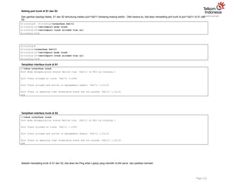
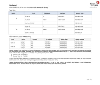
Tabel VLAN
Switch VLAN VLAN NAME Interface Network VLAN
S1
VLAN 10 IT Fa0/1-Fa0/12 192.168.10.0/24
VLAN 20 Admin Fa0/13-Fa0/24 192.168.20.0/24
Interface VLAN10 192.168.10.10
S2
VLAN 10 IT Fa0/1-Fa0/12 192.168.10.0/24
VLAN 20 Admin Fa0/13-Fa0/24 192.168.20.0/24
Interface VLAN10 192.168.10.10
13.
Setting VLAN diS1 dan S2 sesuai dengan tabel VLAN diatas dan setting IP address untuk interface VLAN 10 agar S1 atau S2 dapat diremote melalui telnet.
Setting VLAN di S1 Tampilkan VLAN default di S1
S1#show vlan
VLAN Name Status Ports
1 default active Fa0/1, Fa0/2, Fa0/3, Fa0/4 Fa0/5, Fa0/6, Fa0/7, Fa0/8
Fa0/9, Fa0/10, Fa0/11, Fa0/12 Fa0/13, Fa0/14, Fa0/15, Fa0/16 Fa0/17, Fa0/18, Fa0/19,
Fa0/20 Fa0/21, Fa0/22, Fa0/23, Fa0/24
1002 fddi-default act/unsup
1003 token-ring-default act/unsup
1004 fddinet-default act/unsup
1005 trnet-default act/unsup
VLAN Type SAID MTU Parent RingNo BridgeNo Stp BrdgMode Trans1 Trans2 1 enet 100001 1500 - - - - - 0 0
1002 fddi 101002 1500 - - - - - 0 0
1003 tr 101003 1500 - - - - - 0 0
1004 fdnet 101004 1500 - - - ieee - 0 0
1005 trnet 101005 1500 - - - ibm - 0 0
Remote SPAN VLANs
Primary Secondary Type Ports
S1#
Command membuat VLAN di S1
Page 115
S1(config)#
S1(config)#vlan 10
S1(config-vlan)#name IT S1(config-vlan)#vlan 20 S1(config-vlan)#name Admin
S1(config-vlan)#
S1(config-vlan)#interface range fa0/1-12
S1(config-if-range)#switchport mode access
S1(config-if-range)#switchport access vlan 10
S1(config-if-range)#
S1(config-if-range)#interface range fa0/13-24
S1(config-if-range)#switchport mode access
14.
S1(config-if-range)#switchport access vlan20
S1(config-if-range)# S1(config-if-range)#end
Command setting IP address interface VLAN 10 di S1
S1(config)#
S1(config)#interface vlan 10
S1(config-if)#ip address 192.168.10.10 255.255.255.0
S1(config-if)#no shutdown
S1(config-if)#
S1(config-if)#ip default-gateway 192.168.10.254
S1(config)#
Note : ulangi langkah yang sama diatas untuk membuat VLAN dan Interface VLAN di S2
Verifikasi
Tampilkan show vlan brief setelah disetting VLAN di S1
S1#show vlan brief
VLAN Name Status Ports
1 default active
10 IT active Fa0/1, Fa0/2, Fa0/3, Fa0/4 Fa0/5, Fa0/6, Fa0/7, Fa0/8
Fa0/9, Fa0/10, Fa0/11, Fa0/12
20 Admin active Fa0/13, Fa0/14, Fa0/15, Fa0/16 Fa0/17, Fa0/18, Fa0/19, Fa0/20
Fa0/21, Fa0/22, Fa0/23, Fa0/24
1002 fddi-default active
1003 token-ring-default active
1004 fddinet-default active
1005 trnet-default active S1#
Tampilkan show vlan brief setelah disetting VLAN di S2
S2#show vlan brief
VLAN Name Status Ports
1 default active
10 IT active Fa0/1, Fa0/2, Fa0/3, Fa0/4 Fa0/5, Fa0/6, Fa0/7, Fa0/8
Fa0/9, Fa0/10, Fa0/11, Fa0/12
20 Admin active Fa0/13, Fa0/14, Fa0/15, Fa0/16 Fa0/17, Fa0/18, Fa0/19, Fa0/20
Fa0/21, Fa0/22, Fa0/23, Fa0/24
1002 fddi-default active
1003 token-ring-default active
Page 116
15.
1004 fddinet-default active
1005trnet-default active S2#
Dari hasil ouput show vlan brief diatas, kita terlah berhasil membuat VLAN 10 dan VLAN 20 di S1 dan S2. Dengan status Active pada masing-masing VLAN dan
interface VLAN sudah sesuai dengan tabel VLAN yang diberikan.
Tampilkan show ip interface brief di S1
up up
S1#show ip interface brief
Interface IP-Address OK? Method Status Protocol FastEthernet0/1 unassigned YES manual up up
…
FastEthernet0/24 unassigned YES manual up up
Vlan1 unassigned YES manual administratively down down Vlan10 192.168.10.10 YES manual
S1#
Tampilkan show ip interface brief di S2
up up
Page 117
S2#show ip interface brief
Interface IP-Address OK? Method Status Protocol FastEthernet0/1 unassigned YES manual up up
…
FastEthernet0/24 unassigned YES manual up up
Vlan1 unassigned YES manual administratively down down Vlan10 192.168.10.10 YES manual
S2#
Dari hasil output diatas, interface VLAN 10 telah berhasil disetting IP address. Langkah selanjutnya meremote S1 dari Laptop1. Setting IP Laptop1 terlebih dahulu agar
sesuai dengan network VLAN
10. IP address Laptop1 = 192.168.10.1/24. Diasumsikan switch telah disetting basic switch
configuration misalnya hostname, enable secret, telnet, dll, lihat solution Lab 15-Basic Switch Configuration.
Laptop1>ipconfig
FastEthernet0 Connection:(default port)
Link-local IPv6 Address.........: FE80::201:43FF:FE3A:AEC2 IP Address......................: 192.168.10.1
Subnet Mask.....................: 255.255.255.0
Default Gateway.................: 192.168.10.254
16.
Tes Ping dariLaptop1 ke S1
Page 118
Laptop1>ping 192.168.10.10
Pinging 192.168.10.10 with 32 bytes of data:
Reply from 192.168.10.10: bytes=32 time=1ms TTL=255 Reply from 192.168.10.10: bytes=32 time=0ms TTL=255
Reply from 192.168.10.10: bytes=32 time=0ms TTL=255 Reply from 192.168.10.10: bytes=32 time=0ms TTL=255
Ping statistics for 192.168.10.10:
Packets: Sent = 4, Received = 4, Lost = 0 (0% loss), Approximate round trip times in milli-seconds:
Minimum = 0ms, Maximum = 1ms, Average = 0ms
Telnet dari Laptop1 ke S1
Laptop1>telnet 192.168.10.10
Trying 192.168.10.10 ...Open
User Access Verification Password:
S1>enable Password: S1#
Note: ulangi langkah yang sama diatas untuk tes Ping dari Laptop2 ke S2 dan akses telnet ke S2
Setelah selesai disetting VLAN, maka Laptop1 dan Laptop3 di S1, Laptop2 dan Laptop4 di S2 tidak bisa melakukan Ping karena beda VLAN. Oleh karena itu untuk
mengkoneksikan VLAN yang berbeda membutuhkan device layer 3 yaitu router dan L3 switch.
Laptop1 & Laptop2 menjadi member VLAN10
Laptop3 & Laptop4 menjadi member VLAN 20
Tabel Addressing setelah VLAN disetting
Device Interface IP Address Subnet Mask Default Gateway
Laptop1 NIC 192.168.10.1 255.255.255.0 192.168.10.254
Laptop3 NIC 192.168.20.1 255.255.255.0 192.168.20.254
Laptop2 NIC 192.168.10.2 255.255.255.0 192.168.10.254
Laptop4 NIC 192.168.20.2 255.255.255.0 192.168.20.254
Dari tabel diatas ada yang memiliki network address yang sama, hal ini tidak menjadi masalah karena VLAN terletak beda lokasi yang satu di Network A dan lainnya di
Network B. Dan VLAN ini tidak dikoneksikan menggunakan routing protocol sehingga tidak menyebabkan overlap network.
17.
Tes Ping dariLaptop1 ke Laptop3 setelah disetting VLAN di S1
Page 119
Laptop1>ping 192.168.20.1
Pinging 192.168.20.1 with 32 bytes of data: Request timed out.
Request timed out.
Request timed out.
Request timed out.
Ping statistics for 192.168.20.1:
Packets: Sent = 4, Received = 0, Lost = 4 (100% loss),
Tes Ping gagal dari Laptop1 ke Laptop3 karena beda VLAN dan belum terdapat gateway diantara masing-masing VLAN. Untuk mengatasi hal ini maka diperlukan
InterVLAN menggunakan interface physical router atau sub-interface router (Router-on-Stick).
Review
1. Command apa yang digunakan untuk menghapus VLAN di swith?
2. Hapus VLAN 1 di S1 maupun S2? Bagaimana hasilnya, berhasil atau tidak? Jelaskan?
3. Ubah interface router Fa0/0 R1 dan R2 menjadi 192.168.10.254, kemudian lakukan tes Ping dari S1 dan S2? Bagaimana hasilnya? Jelaskan?
Tujuan
Setting VLANTrunking
Konsep Dasar
Tipe Link/Port
1. Access Port
Hanya mampu memuat satu VLAN
Digunakan oleh end-device
Tidak aware dengan VLAN membership, hanya sebagai member broadcast domain tertentu
Tidak memiliki pemahaman tentang jaringan fisik
Switch akan menghapus informasi VLAN dari frame sebelum dikirimkan ke access link
2. Trunk Port
Dapat melakukan carrier multiple VLAN
Digunakan oleh point-to-point antara dua switch, antara switch dan router, atau antara switch dan server
Mampu memuat trafik multiple VLAN dari VLAN 1 sampai 1005 pada satu waktu
Frame Tagging
Single VLAN bisa di span untuk multiple switch
Untuk memastikan komunikasi antar member VLAN yang sama di switch yang berbeda membutuhkan metode frame tagging di trunk link
Tag ditambahkan sebelum frame dikirimkan dan diremove saat diterima disisi trunk link
Frame tagging hanya terjadi di trunk link
VLAN ID digunakan oleh switch untuk mengetahui semua frame melalui trunk link
Dua trunking protocol yang bertanggung jawab untuk proses frame tagging :
o Inter-Switch Link (ISL)
o IEEE 802.1Q
ISL
Cisco proprietary
Bekerja di Ethernet, Token Ring, FDDI
Menambahkan 30 byte tagging
Semua VLAN ditag
Frame tidak dimodifikasi
IEEE 802.1Q
Open standar, kita dapat menggunakan switch vendor manapun
Hanya bekerja di Ethernet
Hanya menambahkan 4 byte kedalam frame aslinya
Tidak seperti ISL, 802.1Q tidak mengenkapsulasi frame, tetapi memodifikasi eksisting frame untuk menambahkan VLAN ID
Konfigurasi Trunking
Page 121
Switch(config)# interface <interface type> <interface no.>
Switch(config-if) # switchport mode trunk
Switch(config-if) # switchport trunk encapsulation dot1q/ISL
20.
Konfigurasi
Login console keS1 atau S2 untuk mempraktikkan Lab 17-VLAN Trunking.
Tabel VLAN
Page 122
Switch VLAN VLAN NAME Interface IP VLAN
S1
VLAN 10 IT Fa0/1-Fa0/12 192.168.10.0/24
VLAN 20 Admin Fa0/13-Fa0/24 192.168.20.0/24
Interface VLAN10 192.168.10.10
S2
VLAN 10 IT Fa0/1-Fa0/12 192.168.10.0/24
VLAN 20 Admin Fa0/13-Fa0/24 192.168.20.0/24
Interface VLAN10 192.168.10.10
Tabel Addressing setelah VLAN disetting
VLAN Device Interface IP Address Subnet Mask Default Gateway
VLAN 10
Laptop1 NIC 192.168.10.1 255.255.255.0 192.168.10.254
Laptop2 NIC 192.168.20.1 255.255.255.0 192.168.20.254
VLAN 20
Laptop3 NIC 192.168.10.2 255.255.255.0 192.168.10.254
Laptop4 NIC 192.168.20.2 255.255.255.0 192.168.20.254
Dari tabel diatas ada yang memiliki network address yang sama, hal ini tidak menjadi masalah karena VLAN terletak beda lokasi yang satu di Network A dan lainnya di
Network B. Dan VLAN ini tidak dikoneksikan menggunakan routing protocol sehingga tidak menyebabkan overlap network.
Dengan settingan VLAN seperti tabel VLAN dan tabel addressing diatas, untuk menghubungkan antar VLAN yang sama pada switch yang berbeda kita membutuhkan
port dengan mode Trunk antara S1 dan S2. Sedangkan untuk mengkoneksikan VLAN yang berbeda membutuhkan device layer 3 yaitu router dan L3 switch, walaupun
VLAN yang berbeda terletak pada switch yang sama.
21.
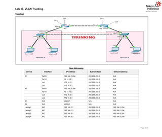
Setting port trunkdi S1 dan S2
Dari gambar topologi diatas, S1 dan S2 terhubung melalui port Fa0/11 dimasing-masing switch. Oleh karena itu, kita akan mensetting port trunk di port Fa0/11 di S1 dan
S2.
Page 123
S1(config)# S1(config)#interface fa0/11
S1(config-if)#switchport mode trunk
S1(config-if)#switchport trunk allowed vlan all
S1(config-if)#
S2(config)#
S2(config)#interface fa0/11
S2(config-if)#switchport mode trunk
S2(config-if)#switchport trunk allowed vlan all
S2(config-if)#
Tampilkan interface trunk di S1
S1#show interface trunk
Port Mode Encapsulation Status Native vlan Fa0/11 on 802.1q trunking 1
Port Vlans allowed on trunk Fa0/11 1-1005
Port Vlans allowed and active in management domain Fa0/11 1,10,20
Port Vlans in spanning tree forwarding state and not pruned Fa0/11 1,10,20
S1#
Tampilkan interface trunk di S2
S2#show interface trunk
Port Mode Encapsulation Status Native vlan Fa0/11 on 802.1q trunking 1
Port Vlans allowed on trunk Fa0/11 1-1005
Port Vlans allowed and active in management domain Fa0/11 1,10,20
Port Vlans in spanning tree forwarding state and not pruned Fa0/11 1,10,20
S2#
Setelah mensetting trunk di S1 dan S2, kita akan tes Ping antar Laptop yang memiliki VLAN sama dan pastikan berhasil.
22.
Tes Ping dariLaptop1 ke Laptop2
Page 124
Laptop1>ping 192.168.10.2
Pinging 192.168.10.2 with 32 bytes of data:
Reply from 192.168.10.2: bytes=32 time=1ms TTL=128 Reply from 192.168.10.2: bytes=32 time=0ms TTL=128
Reply from 192.168.10.2: bytes=32 time=0ms TTL=128 Reply from 192.168.10.2: bytes=32 time=0ms TTL=128
Ping statistics for 192.168.10.2:
Packets: Sent = 4, Received = 4, Lost = 0 (0% loss),
Approximate round trip times in milli-seconds: Minimum = 0ms, Maximum = 1ms, Average = 0ms
Tes Ping dari Laptop3 ke Laptop4
Laptop3>ping 192.168.20.2
Pinging 192.168.20.2 with 32 bytes of data:
Reply from 192.168.20.2: bytes=32 time=0ms TTL=128 Reply from 192.168.20.2: bytes=32 time=0ms TTL=128
Reply from 192.168.20.2: bytes=32 time=1ms TTL=128 Reply from 192.168.20.2: bytes=32 time=0ms TTL=128
Ping statistics for 192.168.20.2:
Packets: Sent = 4, Received = 4, Lost = 0 (0% loss),
Approximate round trip times in milli-seconds: Minimum = 0ms, Maximum = 1ms, Average = 0ms
Verifikasi
Tampilkan show interface trunk di S1
S1#show interface trunk
Port Mode Encapsulation Status Native vlan Fa0/11 on 802.1q trunking 1
Port Vlans allowed on trunk Fa0/11 1-1005
Port Vlans allowed and active in management domain Fa0/11 1,10,20
Port Vlans in spanning tree forwarding state and not pruned Fa0/11 1,10,20
S1#
23.
Tampilkan show interfacetrunk di S2
S2#show interface trunk
Port Mode Encapsulation Status Native vlan Fa0/11 on 802.1q trunking 1
Port Vlans allowed on trunk Fa0/11 1-1005
Port Vlans allowed and active in management domain Fa0/11 1,10,20
Port Vlans in spanning tree forwarding state and not pruned Fa0/11 1,10,20
S2#
Dari hasil ouput show interface trunk diatas, kita telah berhasil menghubungkan VLAN yang sama namun berada pada lokasi switch yang berbeda. Port trunk
memungkinkan komunikasi lebih dari satu VLAN.
Ketika port switch disetting menjadi port trunk, maka di tampilan show vlan brief sudah tidak tampak lagi port switchnya.
Tampilkan show vlan brief di S1
S1#show vlan brief
VLAN Name Status Ports
1 default active
10 IT active Fa0/1, Fa0/2, Fa0/3, Fa0/4 Fa0/5, Fa0/6, Fa0/7, Fa0/8
Fa0/9, Fa0/10, Fa0/12
20 Admin active Fa0/13, Fa0/14, Fa0/15, Fa0/16 Fa0/17, Fa0/18, Fa0/19, Fa0/20
Fa0/21, Fa0/22, Fa0/23, Fa0/24
1002 fddi-default active
1003 token-ring-default active
1004 fddinet-default active
1005 trnet-default active S1#
Page 125
Perhatikan output diatas, port Fa0/11 sudah tidak lagi menjadi member VLAN 10.
Note: ulangi langkah yang sama diatas show vlan brief di S2
Review
1. Apa yang dimaksud dengan Native VLAN?
2. Apa yang terjadi jika S1 dan S2 memiliki Native VLAN yang berbeda? Jelaskan?
3. Bagaimana cara menambahkan, mengurangi, menghapus VLAN di port TRUNK?
Tujuan
Setting InterVLANRouting
Konsep Dasar
Bagaimana interVLAN routing bekerja?
Device network yang berbeda VLAN tidak dapat berkomunikasi dengan device lainnya tanpa router dan L3 switch, yang berfungsi untuk merutekan trafik antar
VLAN
Konfigurasi VLAN bermanfaat untuk mengontrol size broadcast domain dan menjaga trafik local
Untuk mengkoneksikan end-devices didalam satu VLAN dengan VLAN lainnya dibutuhkan komunikasi InterVLAN
InterVLAN membutuhkan interface fisik router atau sub-interface router sebagai gateway masing-masing VLAN dan L3 switch
Penggunaan sub-interface router untuk InterVLAN disebut juga sebagai Router-on-Stick
Sub-interface router untuk InterVLAN membutuhkan protocol trunking ISL atau 802.1Q
Konfigurasi Router-On-Stick
1. Pilih Interface router
2. Setting sub-interface
3. Setting protocol trunking ISL atau 802.1Q
Router(config)# interface fa0/0.10 Router(config-if)# encapsulation dot1q 10 Router(config-if)# ip
address <ip> <subnetmask> Router(config-if)#
Router(config)# interface fa0/0.20
Router(config-if)# encapsulation dot1q 20 Router(config-if)# ip address <ip> <subnetmask>
Router(config-if)#
Router(config-if)# exit
Router(config)# interface fa0/0
Router(config)# no shutdown
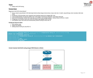
Contoh ilustrasi InterVLAN routing dengan ROS (Router-on-Stick) :
Page 127
26.
Konfigurasi
Login console keS1 atau S2 untuk mempraktikkan Lab 18-InterVLAN Routing.
Tabel VLAN
Page 128
Switch VLAN VLAN NAME Interface Network VLAN
S1
VLAN 10 IT Fa0/1-Fa0/12 192.168.10.0/24
VLAN 20 Admin Fa0/13-Fa0/24 192.168.20.0/24
Interface VLAN10 192.168.10.10
S2
VLAN 10 IT Fa0/1-Fa0/12 192.168.30.0/24
VLAN 20 Admin Fa0/13-Fa0/24 192.168.40.0/24
Interface VLAN10 192.168.30.10
Tabel Addressing setelah VLAN disetting
VLAN Device Interface IP Address Subnet Mask Default Gateway
VLAN 10
Laptop1 NIC 192.168.10.1 255.255.255.0 192.168.10.254
Laptop2 NIC 192.168.20.2 255.255.255.0 192.168.20.254
VLAN 20
Laptop3 NIC 192.168.30.3 255.255.255.0 192.168.30.254
Laptop4 NIC 192.168.40.4 255.255.255.0 192.168.40.254
Dengan settingan VLAN seperti tabel VLAN dan tabel addressing diatas, untuk menghubungkan antar VLAN yang sama pada switch yang berbeda kita membutuhkan
port switch dengan mode Trunk. Sedangkan untuk menghubungkan VLAN yang berbeda kita membutuhkan router atau L3 switch. Untuk menghemat resource interface
router, maka kita akan menggunakan sub-interface untuk gateway masing-masing VLAN.
Gateway VLAN 10 = Fa0/0.10
Gateway VLAN 20 = Fa0/0.20
Trunking selain digunakan untuk switch-to-switch harus disetting juga di switch yang terhubung ke router untuk melewatkan lebih dari satu trafik VLAN. Di sisi port switch
disetting mode trunk, di port router disetting trunking protocol misalnya dengan encapsulation dot1q.
Setelah mensetting trunk di S1 dan S2, kemudian setting encapsulation di Fa0/0 di R1 dan R2, agar VLAN 10 dan VLAN 20 yang berada di S1 dan S2 dapat saling
berkomunikasi. Hal itu dibuktikan dengan tes Ping yang berhasil antar masing-masing Laptop di VLAN yang berbeda.
27.
Setting port trunkdi S1
Dari gambar topologi diatas, S1 dan R1 terhubung melalui port Fa0/24 di switch dan Fa0/0 di R1. Oleh karena itu, kita akan mensetting port trunk di port Fa0/24 di S1.
Page 129
S1(config)# S1(config)#interface fa0/24
S1(config-if)#switchport mode trunk
S1(config-if)#switchport trunk allowed vlan all
S1(config-if)#
S2(config)#
S2(config)#interface fa0/24
S2(config-if)#switchport mode trunk
S2(config-if)#switchport trunk allowed vlan all
S2(config-if)#
Tampilkan interface trunk di S1
S1#show interface trunk
Port Mode Encapsulation Status Native vlan Fa0/24 on 802.1q trunking 1
Port Vlans allowed on trunk Fa0/24 1-1005
Port Vlans allowed and active in management domain Fa0/24 1,10,20
Port Vlans in spanning tree forwarding state and not pruned Fa0/24 1,10,20
S1#
Tampilkan interface trunk di S2
S2#show interface trunk
Port Mode Encapsulation Status Native vlan Fa0/24 on 802.1q trunking 1
Port Vlans allowed on trunk Fa0/24 1-1005
Port Vlans allowed and active in management domain Fa0/24 1,10,20
Port Vlans in spanning tree forwarding state and not pruned Fa0/24 1,10,20
S2#
Setelah mensetting trunk di S1 dan S2, kita akan mensetting encapsulation dot1q di R1 dan R2.
28.
Setting sub-interface diR1
R1(config)#interface fa0/0.10
R1(config-subif)#encapsulation dot1q 10
R1(config-subif)#ip address 192.168.10.254 255.255.255.0
R1(config-subif)#
R1(config-subif)#interface fa0/0.20
R1(config-subif)#encapsulation dot1q 20
R1(config-subif)#ip address 192.168.20.254 255.255.255.0
R1(config-subif)#
R1(config-subif)#interface fa0/0
R1(config-if)#no shutdown
R1(config-if)#
Setting sub-interface di R2
R2(config)#interface fa0/0.10
R2(config-subif)#encapsulation dot1q 10
R2(config-subif)#ip address 192.168.30.254 255.255.255.0
R2(config-subif)#
R2(config-subif)#interface fa0/0.20
R2(config-subif)#encapsulation dot1q 20
R2(config-subif)#ip address 192.168.40.254 255.255.255.0
R2(config-subif)#
R2(config-subif)#interface fa0/0
R2(config-if)#no shutdown
R2(config-if)#
Setelah gateway masing-masing VLAN di R1 dan R2 disetting, maka langkah selanjutnya yaitu tes Ping dari VLAN yang berbeda. Berdasarkan gambar topologi diatas,
maka kita akan tes Ping dari Laptop1 ke Laptop3 dan dari Laptop2 ke Laptop4.
Tes Ping dari Laptop1 ke Laptop3 di Network A
Page 130
Laptop1>ping 192.168.30.3
Pinging 192.168.30.3 with 32 bytes of data:
Reply from 192.168.30.3: bytes=32 time=0ms TTL=127 Reply from 192.168.30.3: bytes=32 time=0ms TTL=127
Reply from 192.168.30.3: bytes=32 time=1ms TTL=127 Reply from 192.168.30.3: bytes=32 time=1ms TTL=127
Ping statistics for 192.168.30.3:
Packets: Sent = 4, Received = 4, Lost = 0 (0% loss), Approximate round trip times in milli-seconds:
Minimum = 0ms, Maximum = 1ms, Average = 0ms
Note: ulangi langkah yang sama diatas untuk tes Ping dari Laptop2 ke Laptop4 di Network B
29.
FastEthernet0/0.10 192.168.10.254 YESmanual up up
FastEthernet0/0.20 192.168.30.254 YES manual up up
Page 131
FastEthernet0/0.10 192.168.20.254 YES manual up up
FastEthernet0/0.20 192.168.40.254 YES manual up up
Verifikasi
Tampilkan show ip interface brief di R1
R1#show ip interface brief
Interface IP-Address OK? Method Status Protocol FastEthernet0/0 unassigned YES NVRAM up up
FastEthernet1/0 12.12.12.1 YES manual up up Loopback1 172.16.1.1 YES manual up up Loopback2
172.16.2.2 YES manual up up
Tampilkan show ip interface brief di R2
R2#show ip interface brief
Interface IP-Address OK? Method Status Protocol FastEthernet0/0 unassigned YES NVRAM up up
FastEthernet1/0 12.12.12.2 YES manual up up Loopback1 172.16.3.3 YES manual up up Loopback2
172.16.4.4 YES manual up up
Dari output yang dihasilkan show ip interface brief diatas, masing-masing VLAN yaitu VLAN 10 dan VLAN 20 telah memiliki gateway sendiri dan sudah bisa tes
Ping antara VLAN 10 dan VLAN 20 di network internal S1 maupun S2.
Review
1. Dari lab InterVLAN Routing ini, VLAN 10 dan VLAN 20 hanya bisa berkomunikasi di satu network saja yaitu VLAN 10 bisa berkomunikasi di VLAN 20 di Network
A saja atau VLAN 10 hanya bisa berkomunikasi dengan VLAN 20 di Network B saja.
Bagaimana caranya supaya VLAN 10 di Network A bisa berkomunikasi dengan VLAN 10 di Network B, begitu juga dengan VLAN 20 di Network A bisa
berkomunikasi dengan VLAN 20 di Network B?
Untuk menjawab pertanyaan no.1, gunakan solution Lab 8-OSPF dengan informasi Area 0 seperti gambar topologi diatas.
2. Praktikkan InterVLAN Routing dengan interface fisik router.
Gunakan topologi dan solution pada Lab 17-VLAN Trunking
Setting Trunking antara S1 dan S2
Setting interface Fa0/0 R1 sebagai Gateway VLAN 10
Setting interface Fa0/0 R2 sebagai Gateway VLAN 20
Terapkan static routing untuk menghubungkan VLAN 10 dan VLAN 20
Tes Ping antar VLAN yang berbeda
Notes: untuk mensetting interface fisik router sebagai gateway VLAN tidak membutuhkan konfigurasi protocol trunking ISL atau 802.1Q
30.
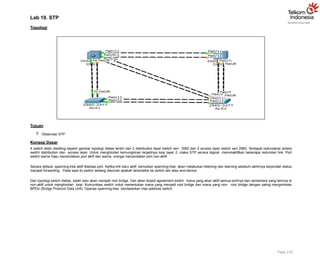
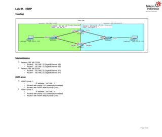
Lab 19. STP
Topologi
Tujuan
Observasi STP
Konsep Dasar
4 switch telah disetting seperti gambar topologi diatas terdiri dari 2 distribution layer switch seri 3560 dan 2 access layer switch seri 2960. Terdapat redundansi antara
switch distribution dan access layer. Untuk menghindari kemungkinan terjadinya loop layer 2, maka STP secara logical menonaktifkan beberapa redundan link. Port
switch warna hijau menandakan port aktif dan warna orange menandakan port non-aktif.
Secara default, spanning-tree aktif disetiap port. Ketika link baru aktif, kemudian spanning-tree akan melakukan listening dan learning sebelum akhirnya berpindah status
menjadi forwarding. Pada saat itu switch sedang discover apakah terkoneksi ke switch lain atau end-device.
Dari topologi switch diatas, salah satu akan menjadi root bridge. Dan akan terjadi agreement switch mana yang akan aktif semua portnya dan sementara yang lainnya di
non-aktif untuk menghindari loop. Komunikasi switch untuk menentukan mana yang menjadi root bridge dan mana yang non- root bridge dengan saling mengirimkan
BPDU (Bridge Protocol Data Unit). Operasi spanning-tree berdasarkan mac-address switch.
Page 132
31.
Verifikasi
Tampilkan informasi spanning-treedisemua switch
Tampilan spanning-tree bisa saja berbeda untuk masing-masing topologi. Karena memang operasi spanning-tree berdasarkan mac-address switch. Dan switch memiliki
mac-address yang berbeda- beda.
Tampilan spanning-tree DLS1 DLS1#show spanning-tree VLAN0001
Spanning tree enabled protocol ieee
Root ID Priority 32769
Address 000C.8560.A349
Cost 19
Port 7(FastEthernet0/7)
Hello Time 2 sec Max Age 20 sec Forward Delay 15 sec
Bridge ID Priority 32769 (priority 32768 sys-id-ext 1) Address 000C.CF75.B926
Hello Time 2 sec Max Age 20 sec Forward Delay 15 sec Aging Time 20
Interface Role Sts Cost Prio.Nbr Type
Fa0/11 Desg FWD 19 128.11 P2p
Fa0/12 Desg FWD 19 128.12 P2p
Fa0/7 Root FWD 19 128.7 P2p
Fa0/8 Altn BLK 19 128.8 P2p
Fa0/10 Desg FWD 19 128.10 P2p
Fa0/9 Desg FWD 19 128.9 P2p
Page 133
DLS1#
32.
Tampilan spanning-tree DLS2DLS2#show
spanning-tree VLAN0001
Spanning tree enabled protocol ieee
Root ID Priority 32769
Address 000C.8560.A349
Cost 38
Port 11(FastEthernet0/11)
Hello Time 2 sec Max Age 20 sec Forward Delay 15 sec
Bridge ID Priority 32769 (priority 32768 sys-id-ext 1) Address 0060.5CAA.5A03
Hello Time 2 sec Max Age 20 sec Forward Delay 15 sec Aging Time 20
Interface Role Sts Cost Prio.Nbr Type
Fa0/7 Altn BLK 19 128.7 P2p
Fa0/8 Altn BLK 19 128.8 P2p
Fa0/11 Root FWD 19 128.11 P2p
Fa0/12 Altn BLK 19 128.12 P2p
DLS2#
Tampilan spanning-tree ALS1 ALS1#show
spanning-tree VLAN0001
Spanning tree enabled protocol ieee
Root ID Priority 32769
Address 000C.8560.A349
This bridge is the root
Hello Time 2 sec Max Age 20 sec Forward Delay 15 sec
Bridge ID Priority 32769 (priority 32768 sys-id-ext 1) Address 000C.8560.A349
Hello Time 2 sec Max Age 20 sec Forward Delay 15 sec Aging Time 20
Interface Role Sts Cost Prio.Nbr Type
Fa0/7 Desg FWD 19 128.7 P2p
Fa0/8 Desg FWD 19 128.8 P2p
Fa0/11 Desg FWD 19 128.11 P2p
Fa0/12 Desg FWD 19 128.12 P2p
Page 134
ALS1#
33.
Tampilan spanning-tree ALS2ALS2#show
spanning-tree VLAN0001
Spanning tree enabled protocol ieee
Root ID Priority 32769
Address 000C.8560.A349
Cost 19
Port 11(FastEthernet0/11)
Hello Time 2 sec Max Age 20 sec Forward Delay 15 sec
Bridge ID Priority 32769 (priority 32768 sys-id-ext 1) Address 00E0.8F21.2D8B
Hello Time 2 sec Max Age 20 sec Forward Delay 15 sec Aging Time 20
Interface Role Sts Cost Prio.Nbr Type
Fa0/12 Altn BLK 19 128.12 P2p
Fa0/11 Root FWD 19 128.11 P2p
Fa0/10 Altn BLK 19 128.10 P2p
Fa0/9 Altn BLK 19 128.9 P2p
Fa0/8 Desg FWD 19 128.8 P2p
Fa0/7 Desg FWD 19 128.7 P2p
Page 135
ALS2#
Sts menyatakan status port, FWD = forwarding, BLK = blocking Dari output diatas :
Port antar switch-to-switch terdapat minimal satu port yang non-aktif (BLK) kecuali root bridge
Port non-aktif atau blocking bisa terjadi di switch distribution atau access-layer
Apabila semua port memiliki settingan default, interface dengan nomor interface yang lebih tinggi yang akan berubah status menjadi blocking
Port menjadi blocking karena switch mendeteksi dua jalur antar switch yang sama
Bridging loop akan terjadi ketika salah satu switch tidak mendisable link secara logical
34.
Review
1. Tampilkan kembalispanning-tree di ALS1
ALS1#show spanning-tree
VLAN0001
Spanning tree enabled protocol ieee
Root ID Priority 32769
Address 000C.8560.A349
This bridge is the root
Hello Time 2 sec Max Age 20 sec Forward Delay 15 sec
Bridge ID Priority 32769 (priority 32768 sys-id-ext 1) Address 000C.8560.A349
Hello Time 2 sec Max Age 20 sec Forward Delay 15 sec Aging Time 20
Interface Role Sts Cost Prio.Nbr Type
Fa0/7 Desg FWD 19 128.7 P2p
Fa0/8 Desg FWD 19 128.8 P2p
Fa0/11 Desg FWD 19 128.11 P2p
Fa0/12 Desg FWD 19 128.12 P2p
Page 136
ALS1#
Setelah melihat output diatas, coba jawab pertanyaan berikut ini :
a) Switch yang mana yang menjadi root bridge?
b) Bagaimana cara mengidentifikasi root bridge?
c) Mengapa switch tersebut terpilih menjadi root bridge?
d) Apa penyebab port switch menjadi blocking?
2. Apabila root bridge dihilangkan dari topology switch diatas, mana yang akan menjadi root bridge? Pilihlah jawaban dibawah ini: a, b, ataukah c?
ALS1(config)#int range fa0/1-24
ALS1(config-if-range)#shutdown
a. DLS1
DLS1#show spanning-tree
VLAN0001
Spanning tree enabled protocol ieee Root ID Priority 32769
Address 000C.CF75.B926
This bridge is the root
Hello Time 2 sec Max Age 20 sec Forward Delay 15 sec
Bridge ID Priority 32769 (priority 32768 sys-id-ext 1) Address 000C.CF75.B926
Hello Time 2 sec Max Age 20 sec Forward Delay 15 sec Aging Time 20
35.
Interface Role StsCost Prio.Nbr Type
Fa0/11 Desg FWD 19 128.11 P2p
Fa0/12 Desg FWD 19 128.12 P2p
Fa0/10 Desg FWD 19 128.10 P2p
Fa0/9 Desg FWD 19 128.9 P2p
DLS1#
b. DLS2
DLS2#show spanning-tree
VLAN0001
Spanning tree enabled protocol ieee Root ID Priority 32769
Address 000C.CF75.B926
Cost 19
Port 11(FastEthernet0/11)
Hello Time 2 sec Max Age 20 sec Forward Delay 15 sec
Bridge ID Priority 32769 (priority 32768 sys-id-ext 1) Address 0060.5CAA.5A03
Hello Time 2 sec Max Age 20 sec Forward Delay 15 sec Aging Time 20
Interface Role Sts Cost Prio.Nbr Type Fa0/7 Desg FWD 19 128.7 P2p
Fa0/8 Desg FWD 19 128.8 P2p
Fa0/11 Root FWD 19 128.11 P2p
Fa0/12 Altn BLK 19 128.12 P2p
DLS2#
Page 137
c. ALS2
ALS2#show spanning-tree
VLAN0001
Spanning tree enabled protocol ieee Root ID Priority 32769
Address 000C.CF75.B926
Cost 19
Port 9(FastEthernet0/9)
Hello Time 2 sec Max Age 20 sec Forward Delay 15 sec
Bridge ID Priority 32769 (priority 32768 sys-id-ext 1) Address 00E0.8F21.2D8B
Hello Time 2 sec Max Age 20 sec Forward Delay 15 sec Aging Time 20
Interface Role Sts Cost Prio.Nbr Type
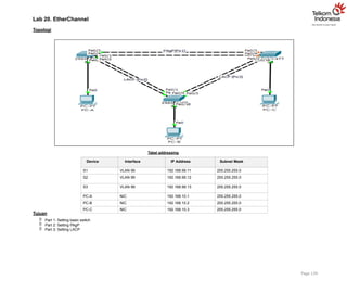
Lab 20. EtherChannel
Topologi
Tabeladdressing
Device Interface IP Address Subnet Mask
S1 VLAN 99 192.168.99.11 255.255.255.0
S2 VLAN 99 192.168.99.12 255.255.255.0
S3 VLAN 99 192.168.99.13 255.255.255.0
PC-A NIC 192.168.10.1 255.255.255.0
PC-B NIC 192.168.10.2 255.255.255.0
PC-C NIC 192.168.10.3 255.255.255.0
Tujuan
Part 1: Setting basic switch
Part 2: Setting PAgP
Part 3: Setting LACP
Page 139
38.
Konsep Dasar
EtherChannel
EtherChanneldigunakan untuk menggabungkan multiple interface fisik menjadi satu interface logical dengan tujuan load sharing dan redundancy
EtherChannel bisa dikonfigurasi :
o Secara manual/static
o Dinamis melalui PAgP (Port Aggregation Protocol)
o Dinamis melalui LACP (IEEE 802.1AD – Link Aggregation Control Protocol)
Cisco 3560 support 8 EtherChannel interface (800 Mbps dengan FastEthernet Interface atau 8 Gbps dengan Gigabit Interface)
Protocol dynamic EtherChannel tergantung dari keyword berikut :
PAgP : Auto dan Desirable
LACP : Passive dan Active
Konfigurasi
Part 1: Konfigurasi Basic Switch
a. Matikan semua switchports kecuali yang terknoneksi ke PC
b. Konfigurasi VLAN 99 dan beri nama Management
c. Konfigurasi VLAN 10 dan beri nama Staff
d. Konfigurasi switch ports yang terkoneksi ke PC dengan VLAN 10
e. Setting IP address PC sesuai tabel addressing diatas
f. Simpan konfigurasi
Part 2: Konfigurasi PAgP
PAgP adalah protocol link aggregation buatan Cisco. Pada bagian ini, link antara S1 dan S3 akan disetting EtherChannel menggunakan PAgP.
Step 1: Konfigurasi PAgP di S1 dan S3
Untuk link antara S1 dan S3, konfigurasi port di S1 dengan mode PAgP desirable dan port di S3 mode PAgP auto. Aktikan port setelah mode PAgP selesai disetting.
Page 140
S1(config)# interface range f0/3-4
S1(config-if-range)# channel-group 1 mode desirable
S1(config-if-range)# no shutdown
S3(config)# interface range f0/3-4
S3(config-if-range)# channel-group 1 mode auto
S3(config-if-range)# no shutdown
Step 2: Tampilkan output konfigurasi
Sekarang interface F0/3, F0/4, dan Po1 (Port-channel1) pada S1 dan S3 sudah berfungsi dengan secara operasional dengan mode administrative dynamic auto.
Verifikasi konfigurasi menggunakan perintah show run interface interface-id dan show interfaces interface-id switchport.
39.
S1# show runinterface f0/3
Building configuration...
Current configuration : 103 bytes
!
interface FastEthernet0/3
Page 141
channel-group 1 mode desirable
Operational Mode: static access (member of bundle Po1)
S1# show interfaces f0/3 switchport
Name: Fa0/3 Switchport: Enabled
Administrative Mode: dynamic auto
Administrative Trunking Encapsulation: dot1q Operational Trunking Encapsulation: native Negotiation of
Trunking: On
Access Mode VLAN: 1 (default)
Trunking Native Mode VLAN: 1 (default) Administrative Native VLAN tagging: enabled Voice VLAN: none
Administrative private-vlan host-association: none Administrative private-vlan mapping: none Administrative
private-vlan trunk native VLAN: none
Administrative private-vlan trunk Native VLAN tagging: enabled Administrative private-vlan trunk encapsulation: dot1q
Administrative private-vlan trunk normal VLANs: none Administrative private-vlan trunk associations: none Administrative
private-vlan trunk mappings: none
Operational private-vlan: none Trunking VLANs Enabled: ALL Pruning VLANs Enabled: 2-1001
Capture Mode Disabled
Capture VLANs Allowed: ALL
Protected: false
Unknown unicast blocked: disabled Unknown multicast blocked: disabled Appliance trust: none
Step 3: Verifikasi bahwa port sudah di aggregasi
S1# show etherchannel summary
Flags: D - down P - bundled in port-channel I - stand-alone s - suspended
H - Hot-standby (LACP only) R - Layer3 S - Layer2
U - in use f - failed to allocate aggregator
M - not in use, minimum links not met u - unsuitable for bundling
w - waiting to be aggregated d - default port
Number of channel-groups in use: 1 Number of aggregators: 1
40.
Group Port-channel ProtocolPorts
+ + +
1 Po1(SU) PAgP Fa0/3(P) Fa0/4(P)
S3# show etherchannel summary
Flags: D - down P - bundled in port-channel I - stand-alone s - suspended
H - Hot-standby (LACP only) R - Layer3 S - Layer2
U - in use f - failed to allocate aggregator
M - not in use, minimum links not met u - unsuitable for bundling
w - waiting to be aggregated d - default port
Number of channel-groups in use: 1 Number of aggregators: 1
Group Port-channel Protocol Ports
+ + +
Page 142
1 Po1(SU) PAgP Fa0/3(P) Fa0/4(P)
Dari output diatas,
S menyatakan port-channel Layer 2 EtherChannel
U menyatakan EtherChannel sedang digunakan
P menyatakan port yang dibundle dengan port-channel
Step 4: Konfigurasi trunk port.
Setelah port di aggregasi, kemudian kita konfigurasi port Po1 di S1 dan S3 sebagai trunk dan setting Po1 menjadi native VLAN 99.
S1(config)# interface port-channel 1
S1(config-if)# switchport mode trunk
S1(config-if)# switchport trunk native vlan 99
S3(config)# interface port-channel 1
S3(config-if)# switchport mode trunk
S3(config-if)# switchport trunk native vlan 99
Step 5: Verifikasi bahwa port-channel sudah dikonfigurasi sebagai trunk.
Ketikkan perintah show run interface interface-id di S1 dan S3. Perhatikan, ketika kita mensetting port-channel menjadi trunk akan memberikan efek terhadap
member link bundle.
S1# show run interface po1
Building configuration...
Current configuration : 92 bytes
!
interface Port-channel1
41.
switchport trunk nativevlan 99
switchport mode trunk
Page 143
switchport trunk native vlan 99
switchport mode trunk
end
S1# show run interface f0/3
Building configuration...
Current configuration : 126 bytes
!
interface FastEthernet0/3
channel-group 1 mode desirable end
Part 3: Konfigurasi LACP
LACP adalah protocol link aggregation yang bersifat open source dan dikembangkan oleh IEEE. Pada bagian 3, link antara S1 dan S2, dan link antara S2 dan S3 akan
dikonfigurasi menggunakan LACP. Link individu akan dikonfigurasi trunk sebelum link dimasukkan ke link bundle sebagai EtherChannel.
Step 1: Konfigurasi LACP antara S1 dan S2.
S1(config)# interface range f0/1-2
S1(config-if-range)# switchport mode trunk
S1(config-if-range)# switchport trunk native vlan 99
S1(config-if-range)# channel-group 2 mode active
S1(config-if-range)# no shutdown
S2(config)# interface range f0/1-2
S2(config-if-range)# switchport mode trunk
S2(config-if-range)# switchport trunk native vlan 99 S2(config-if-range)# channel-group 2 mode passive
S2(config-if-range)# no shutdown
Step 2: Verifikasi bahwa port sudah diaggregasi.
S1# show etherchannel summary
Flags: D - down P - bundled in port-channel I - stand-alone s - suspended
H - Hot-standby (LACP only)
R - Layer3 U -
in use
S - Layer2
f - failed to allocate aggregator
M - not in use, minimum links not met u - unsuitable for
bundling
w - waiting to be aggregated d - default port
Number of channel-groups in use: 2
Number of aggregators: 2
Group Port-channel Protocol Ports
42.
+ + +
1Po1(SU) PAgP Fa0/3(P) Fa0/4(P)
2 Po2(SU) LACP Fa0/1(P) Fa0/2(P)
S2# show etherchannel summary
Flags: D - down P - bundled in port-channel I - stand-alone s - suspended
H - Hot-standby (LACP only) R - Layer3 S - Layer2
U - in use f - failed to allocate aggregator
M - not in use, minimum links not met u - unsuitable for bundling
w - waiting to be aggregated d - default port
Number of channel-groups in use: 1 Number of aggregators: 1
Group Port-channel Protocol Ports
+ + +
Page 144
2 Po2(SU) LACP Fa0/1(P) Fa0/2(P)
Step 3: Konfigurasi LACP antara S2 dan S3.
a. Konfigurasi link antara S2 dan S3 sebagai Po3 dan menggunakan LACP sebagai link aggregation protocol.
S2(config)# interface range f0/3-4
S2(config-if-range)# switchport mode trunk
S2(config-if-range)# switchport trunk native vlan 99
S2(config-if-range)# channel-group 3 mode active
S2(config-if-range)# no shutdown
S3(config)# interface range f0/1-2
S3(config-if-range)# switchport mode trunk
S3(config-if-range)# switchport trunk native vlan 99 S3(config-if-range)# channel-group 3 mode passive
S3(config-if-range)# no shutdown
b. Verifikasi bahwa EtherChannel sudah terbentuk.
S2# show etherchannel summary
Flags: D - down P - bundled in port-channel I - stand-alone s - suspended
H - Hot-standby (LACP only) R - Layer3 S - Layer2
U - in use f - failed to allocate aggregator
M - not in use, minimum links not met u - unsuitable for bundling
w - waiting to be aggregated d - default port
Number of channel-groups in use: 2
43.
Number of aggregators:2
Group Port-channel Protocol Ports
+
2 Po2(SU)
+ + LACP Fa0/1(P) Fa0/2(P)
3 Po3(SU) LACP Fa0/3(P) Fa0/4(P)
S3# show etherchannel summary
Flags: D - down P - bundled in port-channel I - stand-alone s - suspended
H - Hot-standby (LACP only) R - Layer3 S - Layer2
U - in use f - failed to allocate aggregator
M - not in use, minimum links not met u - unsuitable for bundling
w - waiting to be aggregated d - default port
Number of channel-groups in use: 2 Number of aggregators: 2
Group Port-channel Protocol Ports
+
1 Po1(SU)
Page 145
+ + PAgP Fa0/3(P) Fa0/4(P)
3 Po3(SU) LACP Fa0/1(P) Fa0/2(P)
Verifikasi
Verifikasi semua device bisa saling ping pada VLAN yang sama. Jika gagal, lakukan troubleshooting sampai bisa normal konektivitas end-to-end-nya.
Review
1. Apakah load sharing di EtherChannel akan sama rata disetiap interface membernya?
44.
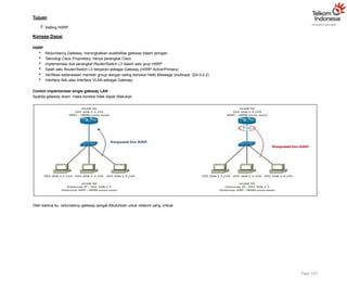
Lab 21. HSRP
Topologi
Tabeladdressing
Network 192.168.1.0/24
o Router0 : 192.168.1.2 (GigabitEthernet 0/0)
o Router1 : 192.168.1.3 (GigabitEthernet 0/0)
Network 192.168.2.0/24
o Router0 : 192.168.2.2 (GigabitEthernet 0/1)
o Router1 : 192.168.2.3 (GigabitEthernet 0/1)
HSRP group
HSRP Group 1 :
o IP address : 192.168.1.1
o Router0 with priority 120 (preemption enabled)
o Router1 with HSRP default priority (100)
HSRP Group 2 :
o IP address : 192.168.2.1
o Router0 with priority 120 (preemption enabled)
o Router1 with HSRP default priority (100)
Page 146
45.
Tujuan
Setting HSRP
KonsepDasar
HSRP
Redundancy Gateway, meningkatkan availibilitas gateway dalam jaringan
Teknologi Cisco Proprietary, hanya perangkat Cisco
Implementasi dua perangkat Router/Switch L3 dalam satu grup HSRP
Salah satu Router/Switch L3 berperan sebagai Gateway (HSRP Active/Primary)
Verifikasi keberadaan member group dengan saling bertukar Hello Message (multicast 224.0.0.2)
Interface fisik atau Interface VLAN sebagai Gateway
Contoh implementasi single gateway LAN
Apabila gateway down, maka koneksi tidak dapat dilakukan
Oleh karena itu, redundancy gateway sangat dibutuhkan untuk network yang critical.
Page 147
46.
Contoh impelementasi redundancygateway
Koneksi pertama dilakukan melalui Catalyst 1 sebagai primary gateway, kemudian terjadi down di Catalyst 1 dan komunikasi dialihkan secara otomatis ke Catalyst 2.
Tingkat prioritas HSRP yang tinggi yang akan menjadi primary gateway. Apabila Catalyst 1 sudah kembali normal, maka komunikasi akan kembali seperti semula yaitu
melalui Catalyst 1.
4 Langkah mudah setting HSRP basic
1. Setting IP address router / VLAN interface
2. Setting Standby Group dan Virtual IP
3. Setting prioriy HSRP
4. Setting preempt (opsional)
Router(config)# interface Vlan 50
Router(config-if)# ip address 192.168.1.10 255.255.255.0
Router(config-if)# standby 1 ip 192.168.1.1
Router(config-if)# standby 1 priority 200
Router(config-if)# standby 1 preempt
Page 148
47.
Konfigurasi
Setting HSRP diRouter0
Page 149
interface GigabitEthernet0/0
ip address 192.168.1.2 255.255.255.0
duplex auto speed auto standby version 2
standby 1 ip 192.168.1.1
standby 1 priority 120
standby 1 preempt
!
interface GigabitEthernet0/1
ip address 192.168.2.2 255.255.255.0
duplex auto speed auto standby version 2
standby 2 ip 192.168.2.1
standby 2 priority 120
standby 2 preempt
Setting HSRP di Router1
interface GigabitEthernet0/0
ip address 192.168.1.3 255.255.255.0
duplex auto speed auto standby version 2
standby 1 ip 192.168.1.1
!
interface GigabitEthernet0/1
ip address 192.168.2.3 255.255.255.0
duplex auto speed auto standby version 2
standby 2 ip 192.168.2.1
Verifikasi
Untuk memverifikasi konfigurasi yang sudah kita setting benar atau belum, lakukan tes berikut ini :
i) Tes Ping dari Laptop0 ke Laptop1
ii) Komunikasi normal akan melalui Router0
iii) Tes Ping lagi dari Laptop0 ke Laptop1 dan secara bersamaan matikan semua interface Router0
iv) Perhatikan output debug di Router1, maka akan tampil output bahwa Router1 akan menjadi Active HSRP
Review
1. Apa bedanya HSRP version 1 dan version 2?
Konsep Dasar
DHCP
DHCP(Dynamic Host Configuration Protocol)
Berfungsi memberikan IP address kepada host secara dinamis
DHCP beroperasi secara klien-server
Proses pertukaran data antara DHCP Server dan DHCP klien
Konfigurasi
Login console ke R1 dan R2 untuk mempraktikkan Lab 22-DHCP. Untuk mensetting DHCP di R1, berikut ini command
yang digunakan :
R1(config)#ip dhcp excluded-address 192.168.1.10 192.168.1.50
R1(config)#
R1(config)#ip dhcp pool Pool_R1
R1(dhcp-config)# network 192.168.1.0 255.255.255.0
R1(dhcp-config)# default-router 192.168.1.254
R1(dhcp-config)# dns-server 192.168.1.254
R1(dhcp-config)# lease 0 23 59
R1(dhcp-config)# domain-name NIXTRAIN.com
R1(dhcp-config)#
Keterangan:
excluded-address : untuk menentukan IP yang tidak boleh di lease oleh DHCP, biasanya berupa IP static untuk server / printer
pool : tentukan nama pool DHCP, misal untuk network 192.168.1.0 namanya Pool_R1
: menentukan network DHCP
: menentukan default gateway untuk klien
: menentukan dns server untuk klien
: lama waktu penggunaan IP dhcp
: menentukan nama domain
network default-router
dns-server lease
domain-name
Page 151
50.
Note: ulangi langkahyang sama diatas untuk mensetting DHCP server di R2
Verifikasi
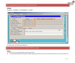
Klik Laptop1 -> Pilih Desktop -> Pilih IP Configuration -> Pilih DHCP
Dari tampilan diatas, DHCP telah berhasil disetting di R1.
Note: ulangi langkah yang sama diatas untuk menampilkan DHCP klien di Laptop2
Review
1. Terkait DHCP, cisco router dapat digunakan menjadi berapa tipe DHCP?
2. Apa yang dimaksud dengan DHCP relay agent? Praktikkan dengan topologi diatas, lokasi DHCP server berada di Network B/R2, dan klien berada di Network A?
Page 152

![g. Setting password vty ciscovty. Aktifkan timeout command sehingga jika selama 5 menit 0 second tidak ada aktifitas maka akan logout sendiri.
S1(config)# line vty 0 4
S1(config-line)# password ciscovty S1(config-line)# exec-timeout 5 0 S1(config-
line)# login
h. Enable enkripsi clear text passwords.
S1(config)# service password-encryption
i. Buat banner yang memberikan informasi kepada user yang tidak memiliki otorisasi dilarang login switch.
S1(config)# banner motd #Unauthorized access is strictly prohibited!#
j. Setting IP address dan interface description. Aktifkan interface vlan 1 dengan sub-command
no-shutdown.
S1(config)# int vlan 1
S1(config-if)# description Connection to VLAN 1 S1(config-if)# ip address 192.168.1.11 255.255.255.0
S1(config-if)# no shutdown
S1(config-if)# exit
S1(config)# exit
S1#
k. Setting default gateway
S1(config)# ip default-gateway 192.168.1.254
l. Simpan konfigurasi file running-configuration ke startup-configuration.
S1# copy running-config startup-config
Destination filename [startup-config]? Building configuration...
[OK] S1#
Ketika kita mensetting switch, maka konfigurasi akan disimpan sementara di file running- configuration (RAM), oleh karena itu proses menyimpan penting
untuk dilakukan agar saat switch reboot atau shutdown file konfigurasi switch masih tetap disimpan di startup- configuration (NVRAM). Cara lain
menyimpan konfigurasi yaitu menggunakan command write memory atau wr mem.
Note: ulangi langkah yang sama untuk mensetting basic switch S2.](https://image.slidesharecdn.com/basicswitchdanvlan-250707125030-bbe106d1/85/Basic-Switch-dan-Vlan-33333333333333333333-4-320.jpg)