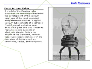
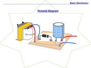
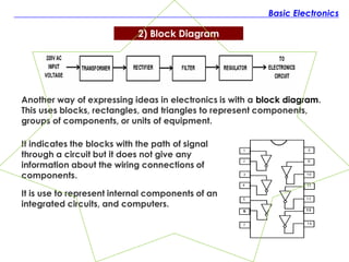
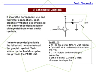
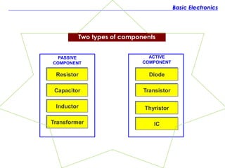
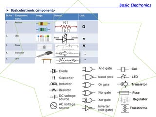
Basic Electronics
1. History of Electronics &
How it started
Basic Electronics
One of the earliest developments in electronics occurred in 1883,
when Thomas Edison, who was studying a weakness in the filament of
his newly developed incandescent lamp, placed a strip of metal in
the bulb and connected it to a battery.
When the bulb was lighted, he found out that electrons flowed from the
filament to the metal strip, although there was no conductor between
them. Edison did not continue to explore this phenomenon until he died,
which later became known as “Edison Effect”.
Shortly after the beginning of this century, other scientists did perform
experiments to learn more about the Edison effect. Among them were
an Englishman, Sir John Fleming, and an American, Dr. Lee De Forest.
Although great progress has been made in electronics since then, but
most experts agree that we have only begun to learn about it.
1. History of Electronics & How it started?
Basic Electronics
Basic Electronics
What is Electronics?
Electronics is a field of engineering and applied physics
dealing with the design and application of devices, usually
electronics circuits. The operation of which depends on the
flow of electrons for the generation, transmission, reception
and storage of information.
ADVENT OF ELECTRONICS INDUSTRY
It was on the afternoon of December 23, 1947, that Walter H.
Brattain and John Bardeen demonstrated the amplifying
action of the first transistor at the Bell Telephone
Laboratories. They presented the action of the original
point-contact transistor.
Basic Electronics
2. ELECTRONIC CIRCUIT
DRAWING
Basic Electronics
The main purpose of using pictorial diagram is to illustrate to the
beginners of what each part looks like, and the appearance of
the wiring circuit.
When intended for assembly lines, the pictorial diagram is use
as a wiring guide that includes color coding of wires and
proper mounting of components.
1) Pictorial Diagram
2) Block Diagram
3) Schematic Diagram
Types of Electronic Drawing
Pictorial Diagram
Basic Electronics
2) Block Diagram
Another way of expressing ideas in electronics is with a block diagram.
This uses blocks, rectangles, and triangles to represent components,
groups of components, or units of equipment.
Basic Electronics
It is use to represent internal components of an
integrated circuits, and computers.
It indicates the blocks with the path of signal
through a circuit but it does not give any
information about the wiring connections of
components.
It shows the components use and
their inter connections. Each
graphic symbols is accompanied
with a reference designation to
distinguish it from other similar
symbols.
Basic Electronics
3) Schematic Diagram
The reference designation is
the letter and number nearest
the graphic symbol. Their
values and actual description
are given in the PARTS LIST.
PARTS LIST:
■ R1- 10 Kilo ohms, ±5%, ¼-watt resistor
■ Q1- 9013 NPN audio output transistor
(TO-92)
■ C1- 470µF/16 volts electrolytic
capacitor
■ SPKR- 8 ohms, 0.5 watt, 2-inch
diameter loud speaker.
Basic Electronics
3. ELECTRONIC DEVICES &
CHARACTERISTICS
Basic Electronics
PASSIVE
COMPONENT
Resistor
Capacitor
Inductor
Transformer
Diode
Transistor
IC
ACTIVE
COMPONENT
Thyristor
Two types of components
Basic Electronics
Basic Electronics

BASIC-ELECTRONICS.pdf fundamentals of mechatronics

  • 2.
    Basic Electronics 1. Historyof Electronics & How it started
  • 3.
    Basic Electronics One ofthe earliest developments in electronics occurred in 1883, when Thomas Edison, who was studying a weakness in the filament of his newly developed incandescent lamp, placed a strip of metal in the bulb and connected it to a battery. When the bulb was lighted, he found out that electrons flowed from the filament to the metal strip, although there was no conductor between them. Edison did not continue to explore this phenomenon until he died, which later became known as “Edison Effect”. Shortly after the beginning of this century, other scientists did perform experiments to learn more about the Edison effect. Among them were an Englishman, Sir John Fleming, and an American, Dr. Lee De Forest. Although great progress has been made in electronics since then, but most experts agree that we have only begun to learn about it. 1. History of Electronics & How it started?
  • 4.
  • 5.
    Basic Electronics What isElectronics? Electronics is a field of engineering and applied physics dealing with the design and application of devices, usually electronics circuits. The operation of which depends on the flow of electrons for the generation, transmission, reception and storage of information. ADVENT OF ELECTRONICS INDUSTRY It was on the afternoon of December 23, 1947, that Walter H. Brattain and John Bardeen demonstrated the amplifying action of the first transistor at the Bell Telephone Laboratories. They presented the action of the original point-contact transistor.
  • 6.
  • 7.
    Basic Electronics The mainpurpose of using pictorial diagram is to illustrate to the beginners of what each part looks like, and the appearance of the wiring circuit. When intended for assembly lines, the pictorial diagram is use as a wiring guide that includes color coding of wires and proper mounting of components. 1) Pictorial Diagram 1) Pictorial Diagram 2) Block Diagram 3) Schematic Diagram Types of Electronic Drawing
  • 8.
  • 9.
    2) Block Diagram Anotherway of expressing ideas in electronics is with a block diagram. This uses blocks, rectangles, and triangles to represent components, groups of components, or units of equipment. Basic Electronics It is use to represent internal components of an integrated circuits, and computers. It indicates the blocks with the path of signal through a circuit but it does not give any information about the wiring connections of components.
  • 10.
    It shows thecomponents use and their inter connections. Each graphic symbols is accompanied with a reference designation to distinguish it from other similar symbols. Basic Electronics 3) Schematic Diagram The reference designation is the letter and number nearest the graphic symbol. Their values and actual description are given in the PARTS LIST. PARTS LIST: ■ R1- 10 Kilo ohms, ±5%, ¼-watt resistor ■ Q1- 9013 NPN audio output transistor (TO-92) ■ C1- 470µF/16 volts electrolytic capacitor ■ SPKR- 8 ohms, 0.5 watt, 2-inch diameter loud speaker.
  • 11.
    Basic Electronics 3. ELECTRONICDEVICES & CHARACTERISTICS
  • 12.
  • 13.
  • 14.