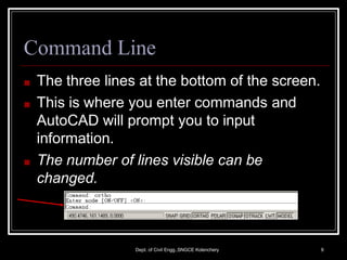
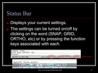
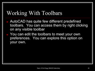
3. AutoCAD
Dept. of Civil Engg.,SNGCE Kolenchery 3
■ AutoCAD is a software
application for computer-aided
design (CAD) and drafting in
both 2D and 3D.
■ It is developed and sold by Autodesk, Inc.
■ First released in December 1982
4. Starting the Program
■ Locate and click on the AutoCAD icon or
use the Start Menu to find the program and
start it.
Dept. of Civil Engg.,SNGCE Kolenchery 4
5.
6. Coordinate Display
Status Line Cursor
Drawing Name
Standard Toolbar
Pull-down Menu Headings
Optional Toolbar
Locations
` 6
Dept. of Civil Engg.,SNGCE Kolenchery
COMMAND LINE
GRAPHICAL DISPLAY WINDOW
7. Drawing Area
Dept. of Civil Engg.,SNGCE Kolenchery 7
■ The large area in the center of the screen.
■ This is where you draw.
■ The size can be changed at any time.
8. Workspaces
■ AutoCAD 2009onwards, a new screen
layout was added.
■ the screen will look different if you are
working on 2D than it will with 3D work.
■ AutoCAD Classic -screen looked as the
versions 2000-2008
Dept. of Civil Engg.,SNGCE Kolenchery 8
9. Command Line
■ The three lines at the bottom of the screen.
■ This is where you enter commands and
AutoCAD will prompt you to input
information.
■ The number of lines visible can be
changed.
Dept. of Civil Engg.,SNGCE Kolenchery 9
10. The Command Line Box
Dept. of Civil Engg.,SNGCE Kolenchery 10
■ There are two basic ways to input a command:
■ The command line
■ Clicking on a command icon. The command icons
will execute the appropriate text based command on
the command line
■ Additionally some commands have a keyboard
shortcut option that normally involves the “cntrl”
or “alt” keys on the keyboard
■ The command line box size can be changed to
show more or fewer command lines.
11. Status Bar
■ Displays your current settings.
■ The settings can be turned on/off by
clicking on the word (SNAP, GRID,
ORTHO, etc) or by pressing the function
keys associated with each.
Dept. of Civil Engg.,SNGCE Kolenchery 11
12. More Grid and Snap
Dept. of Civil Engg.,SNGCE Kolenchery 12
■ It is very common to change the settings for
grid and snap often when creating a
drawing.
■ Grid and Snap (and other drafting settings)
can be enabled by clicking on the Status
Line buttons at the bottom of the AutoCAD
window. These also toggle on and off with
keyboard shortcuts.
13. Setting Grid and Snap Dimensions
Dept. of Civil Engg.,SNGCE Kolenchery 13
■ Drawing accuracy is extremely important in
engineering graphics. Grid and Snap are two of
several commands that help us to ensure
accuracy.
■ An input window is available by using the “tools”
pull-down menu and selecting “Drafting
Settings…”.
■ You can also use the separate command line
commands “snap” and “grid”.
■ Input the parameters that you want to start with.
■ (Eg.:Use a Grid of 1,and a Snap of 0.5)
16. Selection
Dept. of Civil Engg.,SNGCE Kolenchery 16
■ RIGHT TO LEFT-> CROSSING
SELECTION=SECLECTS ANY OBJECT
THAT EITHER CROSSES THE BOUNDARY
OR IS INSIDE IT
■ LEFT TO RIGHT->WINDOW
SELCTION=SELECTS ON OBJECTS
THAT ARE COMPLETELY WITHIN THE
BOX
18. CrossHairs/ Cursor
■ The movement is controlled by the
movement of the pointing device (mouse).
■ Use to locate points, make selections and
draw objects.
Dept. of Civil Engg.,SNGCE Kolenchery 18
19. LWT
Dept. of Civil Engg.,SNGCE Kolenchery 19
■ Lineweight displays the width assigned to
each object.
20. Working With Toolbars
Dept. of Civil Engg.,SNGCE Kolenchery 20
■ AutoCAD has quite few different predefined
toolbars. You can access them by right clicking
on any visible toolbar
■ You can edit the toolbars to meet your own
preferences. You can explore this option on
your own.
21. Setting Up The Drawing
Environment
Dept. of Civil Engg.,SNGCE Kolenchery 21
■ This normally involves a couple of steps.
■ Defining the units
■ Defining drawing limits
■ Setting grid and snap dimensions
■ Using other Drafting Settings
■ Note that you can redefine these items at
anytime.
22. Defining Units
Dept. of Civil Engg.,SNGCE Kolenchery 22
■ Either type “units” on the command line or use
the pull-down menu for “format” and select
“units”
■ For LENGTH units, select the type and
precision.
■ For ANGLE units, select the type, precision, and
direction of measure.
■ The drag-and-drop scale is where you select the
unit system.
■ Click on the “OK” button when done.
24. Define Drawing Limits
Dept. of Civil Engg.,SNGCE Kolenchery 24
■ This defines the extent of the drawing in the
units of the object you are drawing. Since we
are drawing full scale, this should be big enough
to include all parts of your drawing.
■ This can be changed later if you decide to go
larger with your drawing.
■ Type “limits” on the command line or use the
“format” pull down menu and select “Drawing
Limits”
25. Drawing Limits (continued)
Dept. of Civil Engg.,SNGCE Kolenchery 25
■ A prompt appears on the command line for you
to input the coordinates of the lower left corner
of the drawing limits. If the point is within the
current view, you can point and click on the
location of the lower limit. Otherwise, you can
type in the coordinate pair for the point.
■ The next prompt asks for the upper right corner
coordinates. Again, you can either point and
click or type in the coordinate pair.
26. Coordinates
■ At the bottom left of the AutoCAD.
■ Move your cursor around the drawing area and
watch the coordinate change.
■ Toggle “snap” on and off and watch the
difference in the way the coordinates change as
you move the cursor.
■ Toggle three different coordinate modes with
the “f6” keyboard key.
Dept. of Civil Engg.,SNGCE Kolenchery 26
27. Using the Help function
Dept. of Civil Engg.,SNGCE Kolenchery 27
■ AutoCAD has a good command reference in it’s
help function.
■ This presentation will not duplicate that
reference. You should frequently refer to the
command reference as you learn the various
commands.
■ Some practical pointers are added here that
may not be easily encountered in the command
reference.
28. Basic Commands
Dept. of Civil Engg.,SNGCE Kolenchery 28
■ The “Draw” Toolbar
■ Lines L
■ Polylines
■ Circles C
■ Arcs A
■ MI- Mirror
■ CHA- Chamfer
■ The “Modify”
Toolbar
■ Erase E
■ Copy CO
■ Move M
■ Offset O
■ Fillet F
■ Array
■ Trim TR
■ Extend EX
29. Start the Drawing
Dept. of Civil Engg.,SNGCE Kolenchery 29
■ Open AutoCAD or a new drawing
■
■
■
Save the file as “yourname.dwg” in your
directory [D:C6{ur name}]
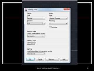
Set the length type to “decimal”, precision to
“0.00”, and the drag-and-drop scale to
“centimeters” or suitable one
Set the limits to:
■
■
Bottom left to 0,0
Top Right to 297,210 for A4 or suitable one
■ To set the view area to drawing limits:
■
■
Enter “zoom” on the command line z
Enter “e” (for extents)
30. Drawing Lines
■ Either type “line” on the command line or
click on the line icon in the draw toolbar.
■ Lines can be drawn by point and click.
■ Can keep an eye on the coordinates display to
make sure that you get what you want.
■ Lines can be specified by their end point
coordinates.
■ Type in the coordinates on the command line
■ Lines can be specified by their first point
coordinates, then by an distance and angle.
■ Select starting point, type in “@distance<angle”
■ Example: @5<45 would go 5 units at a 45
30
degree anglD
e
ept. of Civil Engg.,SNGCE Kolenchery
32. The Copy Command
Dept. of Civil Engg.,SNGCE Kolenchery 32
■ The copy command is used to make a
single duplicate of an entity or group of
entities.
■ Click on copy icon in the modify menu and
follow the instructions on the command line.
■ Note that copy offsets may be independent
of the actual line.
33. Layers
Dept. of Civil Engg.,SNGCE Kolenchery 33
■ Layers are used to organize drawings. It is
necessary to control the drawing and turn
some layers off and view only the ones you
want.
■ You will be creating a layer for the
dimensions, one for the objects (lines that
were drawn) and another for the text. Start
the LAYERcommand (LA).
37. Selecting Objects
Dept. of Civil Engg.,SNGCE Kolenchery 37
■ AutoCAD has several ways to select objects.
■ Click on each object that you want to select.
■ Make a window that encloses all the objects that you
want to select.
■
■ Click on the lower or upper LEFT corner of desired window
area
Click on the opposite corner of the window area
■ Make a boundary that selects every thing that is
within the boundary and that CROSSES the
boundary.
■
■ Click on the lower or upper RIGHT corner of desired window
area
Click on the opposite corner of the window area
38. More drawing
Dept. of Civil Engg.,SNGCE Kolenchery 38
■ Follow the instructor through the process of
creating the objects shown on the handout.
You will learn to use several more draw and
modify commands in the process.
39. Plotting your Drawing
Dept. of Civil Engg.,SNGCE Kolenchery 39
■ Select File>Plot
■ Select Plot Device and choose HP laser
printer
■ Select Plot Settings tab
■ Under Plot Area, choose Limits
■ Under Plot Scale, choose 1:1
■ Under Plot Offset, choose Center
■ Click Full Preview, then if OK,
R-click >Plot
40. Function Keys
Dept. of Civil Engg.,SNGCE Kolenchery 40
■ F1
■ F2
■ F3
■ F4
■ F5
■ F6
HELP
FLIPSCREEN
OSNAP
TABLET
ISOPLANE
COORDINATE DISPLAY
42. Special Function Keys
■
■
■ ESC- Cancels the current
command, menu, or dialog
box.
ENTER- Ends a
command; or will repeat
the previous command if
the command line is blank
SPACE BAR- Same as
the end key except when
entering text.
Dept. of Civil Engg.,SNGCE Kolenchery 42
43. Coordinate Display (F6)
Dept. of Civil Engg.,SNGCE Kolenchery 43
■ In the ABSOLUTE mode: Displays the
location of the crosshairs/ cursor in reference
to the origin. The first number represents the
horizontal (x axis) and the second number
represents the vertical (y axis).
■ In RELATIVE POLAR mode: displays the
distance and angle of the cursor from the last
point entered.
44. SNAP (F9)
Dept. of Civil Engg.,SNGCE Kolenchery 44
■ Increment Snap controls the movement of
the cursor. If it is off the cursor will move
smoothly. If it is ON, the cursor will jump in
an incremental movement. The increment
spacing can be changed, at any time using
TOOLS/DRAFTING SETTINGS. The
default spacing is .250
45. GRID (F7)
Dept. of Civil Engg.,SNGCE Kolenchery 45
■ The grid is merely a visual “drawing aid”.
The default spacing is 1 unit. You may
change the grid spacing at any time using:
TOOLS/DRAFTING SETTINGS.
46. ORTHO (F8)
Dept. of Civil Engg.,SNGCE Kolenchery 46
■ When ORTHO is ON, the cursor movement
is restricted to horizontal or vertical. When
ORTHO is OFF, the cursor is free to move.
47. POLAR (F10)
Dept. of Civil Engg.,SNGCE Kolenchery 47
■ POLAR TRACKING creates “alignment
paths” at specified angles.
48. OSNAP (F3)
Dept. of Civil Engg.,SNGCE Kolenchery 48
■ RUNNING OBJECT SNAP- specific object
snaps can be set to stay active until you
turn them off.
49. OTRACK (F11)
Dept. of Civil Engg.,SNGCE Kolenchery 49
■ OBJECT SNAP TRACKING creates
“alignment paths” at precise positions using
object snap locations.
50. MODEL
Dept. of Civil Engg.,SNGCE Kolenchery 50
■ Switches your drawing between paper
space and model space.
51. BPOLY
Dept. of Civil Engg.,SNGCE Kolenchery 51
■ Common types to bring up the boundary
box.
■ Also used to make line segments for 1
uniform shape.
52. LIST
Dept. of Civil Engg.,SNGCE Kolenchery 52
■ Used to get database info for an object.
■ Layer
■ Space
■ Center Point
■ Radius
■ Start Angle
■ End Angle
■ Length of line or arc
53. Multiple Drawing Environments: MDE
Dept. of Civil Engg.,SNGCE Kolenchery 53
■ You can open as many files as you have
memory for.
■ Like other Windows documents, you can
work in any drawing by minimizing or
maximizing the screen.
■ You can only copy, match properties and
move in MDE.
56. LISP
Dept. of Civil Engg.,SNGCE Kolenchery 56
■ Programs allow you to combine math and
AutoCAD functions and use products in
your CAD drawings.
57. External Reference (XREF)
Dept. of Civil Engg.,SNGCE Kolenchery 57
■ Used to share common objects.
■ Can bring an object from outside and put
on screen, but not into drawing.
■ You can’t change on screen. Can only be
changed at the network server origin.
58. XREF
Dept. of Civil Engg.,SNGCE Kolenchery 58
■ Attach- attach to drawing
■ Detach- discard from drawing
■ Reload- made change from server, hit
reload, and it picks up the current changes.
■ Bind- becomes a block and not an xref.
(Becomes part of the drawing.)
59. When to bind an XREF
Dept. of Civil Engg.,SNGCE Kolenchery 59
■ When you cant non-global changes.
■ When you send work to a client.
60. Linetype Codes
Dept. of Civil Engg.,SNGCE Kolenchery 60
■ Linetypes start with the letter “A”
■ “A” stands for alignment field
■ A positive number represents the length of
a dash
■ A negative number represents the length of
a space
■ A dot will give you a space
61. Plotting
Dept. of Civil Engg.,SNGCE Kolenchery 61
■ #1 (color), #1 (lwt)
■ #2 (color), #2 (lwt)
■ Plot style/ select form view/ color #1, lwt #1,
color #2, lwt #2
62. Plot Units= Drawing Units
Dept. of Civil Engg.,SNGCE Kolenchery 62
■ ¼=1
■ 1/8=1
■ ½=1
1=48
1=96
1=24
63. Stuff you should know/ understand
Dept. of Civil Engg.,SNGCE Kolenchery 63
■ MView= creates viewport in paper space
set aperture size= Tools/options/selection
■ Vmax= zoom max view you can get without
regeneration
■ Nested Block= block within a block
■ If no is used, when you select text to edit,
where does the grip show up?
64. Stuff you should know… cont.
Dept. of Civil Engg.,SNGCE Kolenchery 64
■ In layer names do not use dots.
■ A view is a saved zoom in AutoCAD
■ Items that can be used in naming items
■ Numbers
■ Letters
■ Underscores
■ Hyphens