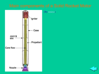
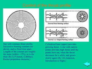
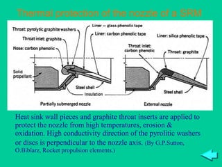
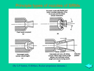
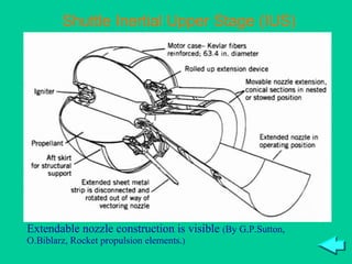
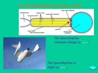
SlideShare a Scribd company logo
1 of 21
Introduction to Astronautics Sissejuhatus kosmonautikasse Vladislav Pust õnski 2009 Tallinn University of Technology
Solid & hybrid propellant rockets ,[object Object],[object Object],[object Object],[object Object],[object Object],[object Object],[object Object],[object Object],[object Object],[object Object],[object Object],[object Object],[object Object],Solid propellant rockets
Propellants A SRM consists of a casing which serves as a wall of the thrust chamber, and a charge of solid propellant inside (called  grain ). A nozzle is attached to the low part of the casing, and some other mechanisms may be included, like an ignitor, a gimbal of the nozzle, small attitude control motors, in the case of multiple use engines, a parachuting system etc. Large SRMs may consist of several sections joined together. For example, the  Solid Rocket Booster (SRB)  of the  Space Shuttle  consists of 4 sections, the strap-on boosters of the  Titans  were multi-sectional as well. The grain may have different shapes. Its outer shape generally repeats the shape of the casing, the internal surface is the exposed area over which the grain burns. There are many possible configurations of the exposed area. Generally, there is a bore along the axis of the motor, the section of this bore (often variable) defines the thrust as function of time. Large SRMs usually have a cylindrical form, smaller ones may be even spherical. Casings of SRMs often have metal walls. They should be firm enough to withstand the internal pressure of the burning charge, and for large motors the required thickness of the wall may be quite large. For example, the casing of the  Shuttle ’s  SRB  is made from steel and its minimum thickness is more than 1 cm. Titanium avails somehow lighter casings designs. However, even titanium casings tend to be heavy, so modern casings are often filament-wound, either Kevlar or graphite fibers in epoxy matrix. The  Shuttle’s  upper stage  IUS  is Kevlar fiber reinforced. The first stage of the future European  Vega  launch vehicle should be made from filament-wound graphite fibers in an epoxy matrix, and this design may be later applied on the SRBs of the  Ariane V . SRMs mostly burn monopropellant mixtures containing different chemicals, among which are
Burning and thrust control When the motor is ignited, burning of the propellant begins. Burning takes place over the exposed area of the propellant, which is usually a shaped bore along the axis of the motor. Actually it is an exothermal deflagration process, when new layers of the propellant react in presence of high temperature and pressure.  Propellant regression rate  r  is the distance the burning front recedes in unit time perpendicular to the exposed surface. An empirical expression for the burning velocity is fuel and oxidizer. Some SRMs burn gunpowder based on nitrocellulose or nitroglycerin where both fuel and oxidizer are present in one molecule. A common fuel used in SRM is aluminum powder, and oxidizer is ammonium perchlorate NH 4 -ClO 4  and ammonium nitrate NH 4 -KNO 3 . Binding agent is also present, that is some polymer, together with catalyst and epoxy curing agents. During the production process, the propellant have a clay-like texture, it is poured into the casing and later hardens as a result of polymerization. The propellant should fulfill certain requirements. It should be stable and not react by itself. Its physical properties should not change significantly with temperature, it should not form cracks due to thermal expansion or under loads. It is critical that the propellant were firm: since burning takes place inside the mass of the propellant, it should withstand the pressure of gases and not to break or crumble. P  is the pressure in the chamber (in  bar )  r 0  is the regression rate at  t  = 20 0 C and  P  = 1  bar ,  B  and  n  are constants depending on the propellant. The value of  B  usually lies in the range 300 0 C – 600 0 C. The burning process
should be stable. It means that if the pressure in the chamber experiences a small growth, the resultant excessive flow of gases through the nozzle should lead to pressure drop, and vice versa: if the pressure diminishes slightly, the outflow from the nozzle should drop so that the pressure returns to the initial value. Analysis shows that burning may be stable only if  n <  1. However, even smaller values of  n  are desirable, since if  n  is close to 1, the pressure in the chamber becomes very sensitive to this value, and it is technologically difficult to ensure predictable properties of the propellant because of the small tolerances. Larger is the area of the burning surface, higher is the thrust (but burning time decreases). Changing the shape of the internal core, it is possible to change the thrust profile. For example, a circular core would mean that the diameter of the bore increases while burning, so the area and the thrust grow as well. A star-shape core is often used since it enables to keep the thrust at a nearly constant level. The burning area recedes, but the surface remains constant. However, different variations of the stellar design enable to program the profile in a wide range of parameters: the profile of the surface evolution depends on the shape of the points of the star. For example, the 11-point star design in the forward segment of the  Shuttle SRB  develops high thrust at the first 65 seconds of flight, but the points burn away by that time, and the thrust temporarily diminishes. The bore configuration is not necessarily constant along the motor: it may change, for instance, from a star on one end to a cylinder on the other end. This adds more flexibility to the thrust programming. There are even more ways to control the thrust profile by the configuration of the inner bores in the case of multi-sectional SRMs, like that of the  Shuttle : each section may have different configuration. On the  Shuttle SRBs , the central and the aft segments have a double-truncated cone bores, which helps to match the thrust profile to the mission needs. Although the thrust profile is relatively simply programmable, it is hardly controllable,
since it is difficult to alter the thrust of a burning SRM. So if a rocket has more than one SRM booster, it is very important to provide equivalence of the thrust profiles of all SRMs, specially if their thrust is large (which is a usual thing). If the thrust of one SRM differs from that of the other(s), the control system may be incapable to compensate the unbalance, and a dangerous situation would develop. This is the reason why production process of identical SRMs should be extensively controlled to avoid possible sources of difference between items. The pressure inside the bore changes along the channel: it is the smallest near the nozzle and the highest at the sealed end of the bore. Since the regression rate is directly related to the local pressure, the grain burns quicker near the sealed end. However, this effect is equilibrated by  erosive burning  – the effect of raising of the regression rate in presence of high-velocity gas flow along the burning surface. Near the nozzle the gas has the highest velocity, so the erosive burning effect is maximal, and this favors uniform burning along the bore. Generally, in the optimal case the grain should be depleted simultaneously along the bore, so that the flame touched the casing simultaneously. That would diminish thermal loads on the casing and unused residuals of unburned propellant. However, some residuals (known as  slivers ) are unavoidable for certain grain configurations like stars. Diminishing these residuals is important to increase the mass ratio and thus, the characteristic velocity. The amount of slivers is about 1% or less with modern designs; in the places where slivers may form the propellant may be replaced by some low-density material to increase the mass ratio. Burning of the grain may be accompanied by instabilities of different types. Instabilities manifest themselves as high-frequency pressure oscillations in the thrust chamber, that are reflected on the thrust. The frequencies are close to acoustic frequencies inside the bore. Radial and tangential oscillations are more probable to appear than axial ones. These pressure oscillations may destroy the grain and the casing. To dampen the instabilities, different
Ignition To ignite a solid rocket motor, it is necessary to simultaneously raise the temperature of the exposed area and the pressure inside the bore to the level that ensures normal burning. For this, electric ignitors are used coupled with special pyrotechnic devices. Upon receiving electric signals, pyrotechnics (which usually is placed near the sealed end of the grain) are quickly ignited and saturate the bore with hot gases at high pressure. The amount of Nozzle and casing thermal protection The nozzle is subject to hot gases from the thrust chamber and thus a strong incident heat flow exists, specially in the throat. Unlike liquid-propellant engines, active cooling methods (regenerative & film cooling) are not available for SRMs in the general case because of the absence of liquid coolant. So only passive cooling methods may be applied, primarily the  ablative cooling ,  i.e.  heat sink by evaporation of layers of special material called  ablation . Nozzles from refractory materials are applied in parallel with the ablation. However, passive cooling methods do not permit the nozzle to withstand high heat flows for a long time. This limits working times of SRMs: they cannot work so long as liquid-propellant engines with regeneratively cooled thrust chambers & nozzles. In some cases film cooling using an external source of liquid is possible. The inner side of the casing is also covered with ablative materials or thermal insulation to protect it from heat when the propellant is nearly depleted and the flame touches the wall. methods are applied. These are: introduction of tube resonators into the chamber, drilling holes or making cavities in the grain, etc.
Nozzle constructions and thrust vector control There are several typical constructions of nozzles of SRMs. Among them are: 1)  fixed nozzle  – the most simple design; 2)  movable nozzle  – a nozzle that may slightly change its direction so that the thrust vector diverges for steering purposes, like on the  Shuttle SRB ; 3)  submerged nozzle  – a part of the nozzle sunk inside the casing, thus the total length of the SRM is shorter (often applied on silo- or submarine-based ICBMs,  i.e.  the  Trident , where length is important); 4)  extendable nozzle (extendable exit cone, EEC)  – a nozzle the extension of which slides from the stored position in order to increase the expansion ratio, like on the  Shuttle IUS . Movable nozzles are used on single-motor stages in order to provide steering in the  yaw  and the  pitch  channel (steering in the  roll  channel should be provided in other way; however, if there are two or more SRMs with vectoring nozzles on a launch vehicle, steering in all channels is provided). They are also used on rockets with powerful strap-on boosters where the liquid-propellant engine has not enough thrust for effective steering – this is the case of the  Shuttle  and the  Ariane V . Such nozzles are typically (partially) submerged. For vectoring, pyrotechnics should by significant for large SRMs. For instance, about 25 kg of pyrotechnics are used to ignite the boosters of  Ariane V . For ignition of very large SRMs, a small rocket motor may be applied (situated inside or outside the bore). When started, this motor provides a supply of hot gases which ignite the grain.
Engine c ut-off and restart a flexible sealed joint is used or a bearing with two actuators 90 0  apart to ensure motion in two planes. On the  Shuttle SRB , hydraulic actuators are used, the mechanical power is provided by special units which decompose hydrazine in gas generators and the gases drive turbopumps. Steering is possible without vectoring the nozzle as well: jet vanes may be used, or injection of gas or liquid into the jet, etc. To avoid complications related to these methods, single-engine solid stages are often spin-stabilized, like the  Shuttle’s   Payload Assist Module (PAM)  upper stage). Extendable nozzles are used in the upper stages. In the stored position the motor is compact (this may be important for the overall length and weight of the launch vehicle: smaller interstages are needed). After separation, the nozzle is extended so that the expansion ratio significantly increases. For instance, in the  Shuttle IUS  the extendable part consists of two sections; when they are set in the operating position, the expansion ration increases from 49.3 to 181, so the specific impulse grows by 14  sec . There is a popular misconception that SRMs cannot be cut of and that they burn until the propellant depletion. It is not so: SRM not only  may  be cut off, but sometimes  should  be cut off. This is the case, for example, of a launch vehicle solid stage that have provided its payload with a required velocity and should be cut off before separation (in order not to collide with the payload). The thrust of the SRM should be diminished quickly. There is a number of methods to cut off a SRM. One of the most reliable methods is
Scaling quick opening of holes in the casing (using pyrotechnical devices), so that the area of the holes were larger than that of the throat. The pressure in the thrust chamber will instantly drop and the burning will cease. These holes may be oriented in reverse direction and additional small nozzles may be applied, so that the opposite thrust will appear, facilitating separation and withdrawing the stage. Other methods include secession of the nozzle extension from the SRM (by pyros); injection of extinguishing liquid or gas into the chamber; etc. The above-mentioned methods do not permit a restart of the SRM. The problem of the restart remains mostly unsolved for practical applications, although some tested methods exist. An example is a multi-sectional charge with the sections separated by insulators. Each section burns until depletion, and the next section is ignited by its own ignitor after removal of the insulator. However, such methods increase the cost and decrease the efficiency of the SRM. This is the reason why the use of re-ignitable SRMs is quite limited. One of the greatest advantages of SRMs is that larger motors may be built by  scaling  of smaller motors. This permits to develop very large motors at a moderate cost. The behavior of a large motor may be studied in detail on small and cheap models. When a large version is built, it should be studied mainly for the issues of instabilities (which cannot be reproduced on a smaller model), other issues would need only minor improvements. The  Shuttle SRB  is an example: having the highest thrust among all rocket motors used in space (about 2 times higher than that of the  F-1  liquid-propellant engine), this multi-sectional SRM was developed relying on the experience of the Titan strap-on boosters, and only 4 static firings of full-scaled motors were sufficient to man-rate the motor (a typical liquid-propellant engine is fired
Hybrid propellant rockets hundreds of times before it may be installed on a launch vehicle). Unfortunately, so far no methods exist for scaling of liquid-propellant engines, so their cost grows very quickly with the size. ,[object Object],[object Object],[object Object],[object Object],[object Object],[object Object],[object Object],[object Object],[object Object],[object Object],[object Object],[object Object]
As it is seen, hybrid motors may be applied where throttling and restart capabilities are required, as well as it is necessary to store the propellant for a long time. Due to their higher  I sp , they may excel SRMs. A common propellant for hybrid motors are  Hydroxil-Terminated Polybutadiene  ( HTPB , synthetic rubber) or  Acronitrile Butadiene Styrene (ABS)  as fuel and LOX or nitrous oxide (N 2 O) as oxidizer. Pressure-fed designs for oxidizer supply are most popular, although supply with a turbopump is also considered in some proposed designs. Since the fuel regression rate in hybrid motors is several times lower than is SRMs, multiple perforations in the fuel grain are required to produce high thrust, so that the oxidizer could effectively mix with the fuel. Since the solid should be vaporized before combustion could occur, the fuel regression speed is related to the coupling aerodynamics of the bore and the heat transfer process to the exposed surface of the grain. When the grain burns, the configuration of the exposed surface and of the bores change, an the mixing process is altered as well. So, the mixture ratio appears to be time function. At the end of the burning process, the size of the bores becomes so large that the oxidizer cannot fully mix with the fuel and is blown through the chamber. Thus, the mixture tends to become oxidizer-rich towards the end of the burning process, and the specific impulse diminishes. In general, it may be said that the disadvantages of hybrid motors compared to solid motors (more complex and less reliable design, problems with the mixture ratio) have been higher so far than their advantages ( throttability  & restartability, safer handling). When trottability & restartability are important, a liquid-propellant engine could often provide better results due to its higher performance ( I sp ) and controllability. This is the reason why hybrid motors have not been used yet in space applications, except for the  SpaceShipOne  suborbital plane.
End of the Lecture 10
Main components of a Solid Rocket Motor (By  source )
Shapes of Solid Rocket Motors GEM 40 SRB, used on Delta II  (By  source ) Central bore inside SRM  (By  source ) Small sperical SRM  (By  source )
Control of the thrust profile Star with constant thrust profile. Successive burning contours are shown, each a fixed time apart. Lengths of the conours are roughly the same (within ~15%), so is the thust (By G.P.Sutton, O.Biblarz, Rocket propulsion elements.) Cylindrical bore (upper) provides growing thrust. A star with narrow points provides high thrust until the points burn out, when the thrust decreases for a while, and grows slowly again (By J.D.Anderson, Introduction to flight.)
Example Shuttle SRB thrust profile  (By  source ) Shuttle SRB thrust profile
Thermal protection of the nozzle of a SRM Heat sink wall pieces and graphite throat inserts are applied to protect the nozzle from high temperatures, erosion & oxidation. High conductivity direction of the pyrolitic washers or discs is perpendicular to the nozzle axis.   ( By G.P.Sutton, O.Biblarz, Rocket propulsion elements. )
Principle types of nozzles of SRMs (By G.P.Sutton, O.Biblarz, Rocket propulsion elements.)
Shuttle Inertial Upper Stage (IUS) Extendable nozzle construction is visible  ( By G.P.Sutton, O.Biblarz, Rocket propulsion elements. )
The SpaceShipOne hybrid rocket The SpaceShipOne schematic design   (By  source ) The SpaceShipOne in flight   (By  source )

More Related Content

What's hot

Belleville washers design and use
Belleville washers design and useBelleville washers design and use
Belleville washers design and usePhoenix Specialty
 
Shallow foundation(by indrajit mitra)01
Shallow   foundation(by indrajit mitra)01Shallow   foundation(by indrajit mitra)01
Shallow foundation(by indrajit mitra)01Indrajit Ind
 
HV tower design 1
HV tower design 1HV tower design 1
HV tower design 1Thy Khy
 
Combined footings
Combined footingsCombined footings
Combined footingsseemavgiri
 
Bearing preload tcm 12-299896
Bearing preload tcm 12-299896Bearing preload tcm 12-299896
Bearing preload tcm 12-299896srabon1059
 
Storagetanks2010edition
Storagetanks2010editionStoragetanks2010edition
Storagetanks2010editionSrini Vasan
 
52436966 lecture-13-plate-girders
52436966 lecture-13-plate-girders52436966 lecture-13-plate-girders
52436966 lecture-13-plate-girdersSaleem Malik
 
Mechanical Design and Analysis of Steel Stack by Varying its Height with Cons...
Mechanical Design and Analysis of Steel Stack by Varying its Height with Cons...Mechanical Design and Analysis of Steel Stack by Varying its Height with Cons...
Mechanical Design and Analysis of Steel Stack by Varying its Height with Cons...IRJET Journal
 
Computer aided foundation design
Computer aided                           foundation designComputer aided                           foundation design
Computer aided foundation designRahul Sharma
 
Footing design 10.01.03.054
Footing design 10.01.03.054Footing design 10.01.03.054
Footing design 10.01.03.054Lamia Efa
 

What's hot (16)

Combined footing 1-1-18
Combined footing 1-1-18Combined footing 1-1-18
Combined footing 1-1-18
 
Bearings
BearingsBearings
Bearings
 
Combined footing
Combined footingCombined footing
Combined footing
 
Belleville washers design and use
Belleville washers design and useBelleville washers design and use
Belleville washers design and use
 
Shallow foundation(by indrajit mitra)01
Shallow   foundation(by indrajit mitra)01Shallow   foundation(by indrajit mitra)01
Shallow foundation(by indrajit mitra)01
 
HV tower design 1
HV tower design 1HV tower design 1
HV tower design 1
 
Combined footings
Combined footingsCombined footings
Combined footings
 
Bearing preload tcm 12-299896
Bearing preload tcm 12-299896Bearing preload tcm 12-299896
Bearing preload tcm 12-299896
 
Storagetanks2010edition
Storagetanks2010editionStoragetanks2010edition
Storagetanks2010edition
 
52436966 lecture-13-plate-girders
52436966 lecture-13-plate-girders52436966 lecture-13-plate-girders
52436966 lecture-13-plate-girders
 
dam
damdam
dam
 
Piston design
Piston designPiston design
Piston design
 
Mechanical Design and Analysis of Steel Stack by Varying its Height with Cons...
Mechanical Design and Analysis of Steel Stack by Varying its Height with Cons...Mechanical Design and Analysis of Steel Stack by Varying its Height with Cons...
Mechanical Design and Analysis of Steel Stack by Varying its Height with Cons...
 
Extender flyer 10 10
Extender flyer 10 10Extender flyer 10 10
Extender flyer 10 10
 
Computer aided foundation design
Computer aided                           foundation designComputer aided                           foundation design
Computer aided foundation design
 
Footing design 10.01.03.054
Footing design 10.01.03.054Footing design 10.01.03.054
Footing design 10.01.03.054
 

Viewers also liked

The space shuttle
The space shuttleThe space shuttle
The space shuttlemstcmath
 
Space shuttle Tiffany Sindel
Space shuttle Tiffany SindelSpace shuttle Tiffany Sindel
Space shuttle Tiffany Sindelmstcmath
 
Space Shuttle
Space ShuttleSpace Shuttle
Space ShuttleJohn *
 
Space shuttle presentation derek
Space shuttle presentation derekSpace shuttle presentation derek
Space shuttle presentation derekmstcmath
 
Liquid propulsion ppt
Liquid propulsion pptLiquid propulsion ppt
Liquid propulsion pptSreekanth G
 
Probni rad
Probni radProbni rad
Probni radandrejtt
 
Note classical
Note classicalNote classical
Note classicalranil2010
 
Sogo Ishii
Sogo IshiiSogo Ishii
Sogo IshiiR9T
 
[plan politika] [Pemuda dan Politik Indonesia]Indonesian Youth and Politics :...
[plan politika] [Pemuda dan Politik Indonesia]Indonesian Youth and Politics :...[plan politika] [Pemuda dan Politik Indonesia]Indonesian Youth and Politics :...
[plan politika] [Pemuda dan Politik Indonesia]Indonesian Youth and Politics :...Plan Politika
 
weekly news 23rd Aug to 28th Aug
weekly news 23rd Aug to 28th Augweekly news 23rd Aug to 28th Aug
weekly news 23rd Aug to 28th AugNitin Kochhar
 
Changing the Status Quo for Small Business IT Solutions
Changing the Status Quo for Small Business IT SolutionsChanging the Status Quo for Small Business IT Solutions
Changing the Status Quo for Small Business IT SolutionsBilal Jaffery
 
1. overcoming facebook marketing myths
1. overcoming facebook marketing myths1. overcoming facebook marketing myths
1. overcoming facebook marketing mythshenry7vernon
 
Rct Pi M Consistory Presentation 060810
Rct Pi M Consistory Presentation 060810Rct Pi M Consistory Presentation 060810
Rct Pi M Consistory Presentation 060810Robert Wingate
 

Viewers also liked (20)

P1
P1P1
P1
 
The space shuttle
The space shuttleThe space shuttle
The space shuttle
 
Space shuttle Tiffany Sindel
Space shuttle Tiffany SindelSpace shuttle Tiffany Sindel
Space shuttle Tiffany Sindel
 
SPACE SHUTTLE
SPACE SHUTTLESPACE SHUTTLE
SPACE SHUTTLE
 
Space Shuttle
Space ShuttleSpace Shuttle
Space Shuttle
 
Space shuttle presentation derek
Space shuttle presentation derekSpace shuttle presentation derek
Space shuttle presentation derek
 
SPACE SHUTTLE
SPACE SHUTTLESPACE SHUTTLE
SPACE SHUTTLE
 
Space Shuttles & Advancement
Space Shuttles & AdvancementSpace Shuttles & Advancement
Space Shuttles & Advancement
 
Liquid propulsion ppt
Liquid propulsion pptLiquid propulsion ppt
Liquid propulsion ppt
 
rocket propellent ppt
rocket propellent pptrocket propellent ppt
rocket propellent ppt
 
Probni rad
Probni radProbni rad
Probni rad
 
Note classical
Note classicalNote classical
Note classical
 
The BUZZ on Tablets in Higher Ed
The BUZZ on Tablets in Higher EdThe BUZZ on Tablets in Higher Ed
The BUZZ on Tablets in Higher Ed
 
Sogo Ishii
Sogo IshiiSogo Ishii
Sogo Ishii
 
Hti
HtiHti
Hti
 
[plan politika] [Pemuda dan Politik Indonesia]Indonesian Youth and Politics :...
[plan politika] [Pemuda dan Politik Indonesia]Indonesian Youth and Politics :...[plan politika] [Pemuda dan Politik Indonesia]Indonesian Youth and Politics :...
[plan politika] [Pemuda dan Politik Indonesia]Indonesian Youth and Politics :...
 
weekly news 23rd Aug to 28th Aug
weekly news 23rd Aug to 28th Augweekly news 23rd Aug to 28th Aug
weekly news 23rd Aug to 28th Aug
 
Changing the Status Quo for Small Business IT Solutions
Changing the Status Quo for Small Business IT SolutionsChanging the Status Quo for Small Business IT Solutions
Changing the Status Quo for Small Business IT Solutions
 
1. overcoming facebook marketing myths
1. overcoming facebook marketing myths1. overcoming facebook marketing myths
1. overcoming facebook marketing myths
 
Rct Pi M Consistory Presentation 060810
Rct Pi M Consistory Presentation 060810Rct Pi M Consistory Presentation 060810
Rct Pi M Consistory Presentation 060810
 

Similar to Astronautics lecture10

Heat Transfer Analysis to Optimize The Water Cooling Scheme For Combustion De...
Heat Transfer Analysis to Optimize The Water Cooling Scheme For Combustion De...Heat Transfer Analysis to Optimize The Water Cooling Scheme For Combustion De...
Heat Transfer Analysis to Optimize The Water Cooling Scheme For Combustion De...IJERA Editor
 
Plasma spraying (type of thernal spraying)
Plasma spraying (type of thernal spraying)Plasma spraying (type of thernal spraying)
Plasma spraying (type of thernal spraying)ROLWYN CARDOZA
 
Steam Turbine Parts.pdf
Steam Turbine Parts.pdfSteam Turbine Parts.pdf
Steam Turbine Parts.pdfKAhmedRehman
 
BASIC PARTS OF STEAM TURBINE
BASIC PARTS OF STEAM TURBINEBASIC PARTS OF STEAM TURBINE
BASIC PARTS OF STEAM TURBINESONAM PALJOR
 
Chapter 32Hardening .ppt
Chapter 32Hardening .pptChapter 32Hardening .ppt
Chapter 32Hardening .pptFoisolAhmed
 
HT 6.6 KV VCB OPERATION AND MAINTENANCE PPT
HT 6.6 KV VCB OPERATION AND MAINTENANCE PPTHT 6.6 KV VCB OPERATION AND MAINTENANCE PPT
HT 6.6 KV VCB OPERATION AND MAINTENANCE PPTprasenjitmsit22
 
FINAL Report for Development of Enclosed Combustion Right for SCRAMJET Fuel S...
FINAL Report for Development of Enclosed Combustion Right for SCRAMJET Fuel S...FINAL Report for Development of Enclosed Combustion Right for SCRAMJET Fuel S...
FINAL Report for Development of Enclosed Combustion Right for SCRAMJET Fuel S...Dan Martin
 
New rich text document
New rich text documentNew rich text document
New rich text documentmanojg1990
 
Plasma Arc Machining (Modern Manufacturing Process)
Plasma Arc Machining (Modern Manufacturing Process)Plasma Arc Machining (Modern Manufacturing Process)
Plasma Arc Machining (Modern Manufacturing Process)Dinesh Panchal
 
ICR OFT April
ICR OFT AprilICR OFT April
ICR OFT AprilTom Lowes
 
Me 1999-mar4 - predicting durability
Me 1999-mar4 - predicting durabilityMe 1999-mar4 - predicting durability
Me 1999-mar4 - predicting durabilitySandeep (Sandy) Muju
 
Nuclear thermal rocket
Nuclear thermal rocketNuclear thermal rocket
Nuclear thermal rocketDeborah Joseph
 
International Journal of Engineering Research and Development
International Journal of Engineering Research and DevelopmentInternational Journal of Engineering Research and Development
International Journal of Engineering Research and DevelopmentIJERD Editor
 
turbine and its construction
turbine and its constructionturbine and its construction
turbine and its constructionMayur Ekhande
 
Scale formation and its removal in hot rolling process
Scale formation and its removal in hot rolling processScale formation and its removal in hot rolling process
Scale formation and its removal in hot rolling processRadi Nasr
 

Similar to Astronautics lecture10 (20)

H48076265
H48076265H48076265
H48076265
 
Heat Transfer Analysis to Optimize The Water Cooling Scheme For Combustion De...
Heat Transfer Analysis to Optimize The Water Cooling Scheme For Combustion De...Heat Transfer Analysis to Optimize The Water Cooling Scheme For Combustion De...
Heat Transfer Analysis to Optimize The Water Cooling Scheme For Combustion De...
 
Plasma spraying (type of thernal spraying)
Plasma spraying (type of thernal spraying)Plasma spraying (type of thernal spraying)
Plasma spraying (type of thernal spraying)
 
Steam Turbine Parts.pdf
Steam Turbine Parts.pdfSteam Turbine Parts.pdf
Steam Turbine Parts.pdf
 
BASIC PARTS OF STEAM TURBINE
BASIC PARTS OF STEAM TURBINEBASIC PARTS OF STEAM TURBINE
BASIC PARTS OF STEAM TURBINE
 
Piston and connecting rod
Piston and connecting rodPiston and connecting rod
Piston and connecting rod
 
Vivek
VivekVivek
Vivek
 
Chapter 32Hardening .ppt
Chapter 32Hardening .pptChapter 32Hardening .ppt
Chapter 32Hardening .ppt
 
HT 6.6 KV VCB OPERATION AND MAINTENANCE PPT
HT 6.6 KV VCB OPERATION AND MAINTENANCE PPTHT 6.6 KV VCB OPERATION AND MAINTENANCE PPT
HT 6.6 KV VCB OPERATION AND MAINTENANCE PPT
 
FINAL Report for Development of Enclosed Combustion Right for SCRAMJET Fuel S...
FINAL Report for Development of Enclosed Combustion Right for SCRAMJET Fuel S...FINAL Report for Development of Enclosed Combustion Right for SCRAMJET Fuel S...
FINAL Report for Development of Enclosed Combustion Right for SCRAMJET Fuel S...
 
New rich text document
New rich text documentNew rich text document
New rich text document
 
combustion champer
combustion champercombustion champer
combustion champer
 
Plasma Arc Machining (Modern Manufacturing Process)
Plasma Arc Machining (Modern Manufacturing Process)Plasma Arc Machining (Modern Manufacturing Process)
Plasma Arc Machining (Modern Manufacturing Process)
 
ICR OFT April
ICR OFT AprilICR OFT April
ICR OFT April
 
Me 1999-mar4 - predicting durability
Me 1999-mar4 - predicting durabilityMe 1999-mar4 - predicting durability
Me 1999-mar4 - predicting durability
 
Nuclear thermal rocket
Nuclear thermal rocketNuclear thermal rocket
Nuclear thermal rocket
 
International Journal of Engineering Research and Development
International Journal of Engineering Research and DevelopmentInternational Journal of Engineering Research and Development
International Journal of Engineering Research and Development
 
G1084857
G1084857G1084857
G1084857
 
turbine and its construction
turbine and its constructionturbine and its construction
turbine and its construction
 
Scale formation and its removal in hot rolling process
Scale formation and its removal in hot rolling processScale formation and its removal in hot rolling process
Scale formation and its removal in hot rolling process
 

Astronautics lecture10

  • 1. Introduction to Astronautics Sissejuhatus kosmonautikasse Vladislav Pust õnski 2009 Tallinn University of Technology
  • 2.
  • 3. Propellants A SRM consists of a casing which serves as a wall of the thrust chamber, and a charge of solid propellant inside (called grain ). A nozzle is attached to the low part of the casing, and some other mechanisms may be included, like an ignitor, a gimbal of the nozzle, small attitude control motors, in the case of multiple use engines, a parachuting system etc. Large SRMs may consist of several sections joined together. For example, the Solid Rocket Booster (SRB) of the Space Shuttle consists of 4 sections, the strap-on boosters of the Titans were multi-sectional as well. The grain may have different shapes. Its outer shape generally repeats the shape of the casing, the internal surface is the exposed area over which the grain burns. There are many possible configurations of the exposed area. Generally, there is a bore along the axis of the motor, the section of this bore (often variable) defines the thrust as function of time. Large SRMs usually have a cylindrical form, smaller ones may be even spherical. Casings of SRMs often have metal walls. They should be firm enough to withstand the internal pressure of the burning charge, and for large motors the required thickness of the wall may be quite large. For example, the casing of the Shuttle ’s SRB is made from steel and its minimum thickness is more than 1 cm. Titanium avails somehow lighter casings designs. However, even titanium casings tend to be heavy, so modern casings are often filament-wound, either Kevlar or graphite fibers in epoxy matrix. The Shuttle’s upper stage IUS is Kevlar fiber reinforced. The first stage of the future European Vega launch vehicle should be made from filament-wound graphite fibers in an epoxy matrix, and this design may be later applied on the SRBs of the Ariane V . SRMs mostly burn monopropellant mixtures containing different chemicals, among which are
  • 4. Burning and thrust control When the motor is ignited, burning of the propellant begins. Burning takes place over the exposed area of the propellant, which is usually a shaped bore along the axis of the motor. Actually it is an exothermal deflagration process, when new layers of the propellant react in presence of high temperature and pressure. Propellant regression rate r is the distance the burning front recedes in unit time perpendicular to the exposed surface. An empirical expression for the burning velocity is fuel and oxidizer. Some SRMs burn gunpowder based on nitrocellulose or nitroglycerin where both fuel and oxidizer are present in one molecule. A common fuel used in SRM is aluminum powder, and oxidizer is ammonium perchlorate NH 4 -ClO 4 and ammonium nitrate NH 4 -KNO 3 . Binding agent is also present, that is some polymer, together with catalyst and epoxy curing agents. During the production process, the propellant have a clay-like texture, it is poured into the casing and later hardens as a result of polymerization. The propellant should fulfill certain requirements. It should be stable and not react by itself. Its physical properties should not change significantly with temperature, it should not form cracks due to thermal expansion or under loads. It is critical that the propellant were firm: since burning takes place inside the mass of the propellant, it should withstand the pressure of gases and not to break or crumble. P is the pressure in the chamber (in bar ) r 0 is the regression rate at t = 20 0 C and P = 1 bar , B and n are constants depending on the propellant. The value of B usually lies in the range 300 0 C – 600 0 C. The burning process
  • 5. should be stable. It means that if the pressure in the chamber experiences a small growth, the resultant excessive flow of gases through the nozzle should lead to pressure drop, and vice versa: if the pressure diminishes slightly, the outflow from the nozzle should drop so that the pressure returns to the initial value. Analysis shows that burning may be stable only if n < 1. However, even smaller values of n are desirable, since if n is close to 1, the pressure in the chamber becomes very sensitive to this value, and it is technologically difficult to ensure predictable properties of the propellant because of the small tolerances. Larger is the area of the burning surface, higher is the thrust (but burning time decreases). Changing the shape of the internal core, it is possible to change the thrust profile. For example, a circular core would mean that the diameter of the bore increases while burning, so the area and the thrust grow as well. A star-shape core is often used since it enables to keep the thrust at a nearly constant level. The burning area recedes, but the surface remains constant. However, different variations of the stellar design enable to program the profile in a wide range of parameters: the profile of the surface evolution depends on the shape of the points of the star. For example, the 11-point star design in the forward segment of the Shuttle SRB develops high thrust at the first 65 seconds of flight, but the points burn away by that time, and the thrust temporarily diminishes. The bore configuration is not necessarily constant along the motor: it may change, for instance, from a star on one end to a cylinder on the other end. This adds more flexibility to the thrust programming. There are even more ways to control the thrust profile by the configuration of the inner bores in the case of multi-sectional SRMs, like that of the Shuttle : each section may have different configuration. On the Shuttle SRBs , the central and the aft segments have a double-truncated cone bores, which helps to match the thrust profile to the mission needs. Although the thrust profile is relatively simply programmable, it is hardly controllable,
  • 6. since it is difficult to alter the thrust of a burning SRM. So if a rocket has more than one SRM booster, it is very important to provide equivalence of the thrust profiles of all SRMs, specially if their thrust is large (which is a usual thing). If the thrust of one SRM differs from that of the other(s), the control system may be incapable to compensate the unbalance, and a dangerous situation would develop. This is the reason why production process of identical SRMs should be extensively controlled to avoid possible sources of difference between items. The pressure inside the bore changes along the channel: it is the smallest near the nozzle and the highest at the sealed end of the bore. Since the regression rate is directly related to the local pressure, the grain burns quicker near the sealed end. However, this effect is equilibrated by erosive burning – the effect of raising of the regression rate in presence of high-velocity gas flow along the burning surface. Near the nozzle the gas has the highest velocity, so the erosive burning effect is maximal, and this favors uniform burning along the bore. Generally, in the optimal case the grain should be depleted simultaneously along the bore, so that the flame touched the casing simultaneously. That would diminish thermal loads on the casing and unused residuals of unburned propellant. However, some residuals (known as slivers ) are unavoidable for certain grain configurations like stars. Diminishing these residuals is important to increase the mass ratio and thus, the characteristic velocity. The amount of slivers is about 1% or less with modern designs; in the places where slivers may form the propellant may be replaced by some low-density material to increase the mass ratio. Burning of the grain may be accompanied by instabilities of different types. Instabilities manifest themselves as high-frequency pressure oscillations in the thrust chamber, that are reflected on the thrust. The frequencies are close to acoustic frequencies inside the bore. Radial and tangential oscillations are more probable to appear than axial ones. These pressure oscillations may destroy the grain and the casing. To dampen the instabilities, different
  • 7. Ignition To ignite a solid rocket motor, it is necessary to simultaneously raise the temperature of the exposed area and the pressure inside the bore to the level that ensures normal burning. For this, electric ignitors are used coupled with special pyrotechnic devices. Upon receiving electric signals, pyrotechnics (which usually is placed near the sealed end of the grain) are quickly ignited and saturate the bore with hot gases at high pressure. The amount of Nozzle and casing thermal protection The nozzle is subject to hot gases from the thrust chamber and thus a strong incident heat flow exists, specially in the throat. Unlike liquid-propellant engines, active cooling methods (regenerative & film cooling) are not available for SRMs in the general case because of the absence of liquid coolant. So only passive cooling methods may be applied, primarily the ablative cooling , i.e. heat sink by evaporation of layers of special material called ablation . Nozzles from refractory materials are applied in parallel with the ablation. However, passive cooling methods do not permit the nozzle to withstand high heat flows for a long time. This limits working times of SRMs: they cannot work so long as liquid-propellant engines with regeneratively cooled thrust chambers & nozzles. In some cases film cooling using an external source of liquid is possible. The inner side of the casing is also covered with ablative materials or thermal insulation to protect it from heat when the propellant is nearly depleted and the flame touches the wall. methods are applied. These are: introduction of tube resonators into the chamber, drilling holes or making cavities in the grain, etc.
  • 8. Nozzle constructions and thrust vector control There are several typical constructions of nozzles of SRMs. Among them are: 1) fixed nozzle – the most simple design; 2) movable nozzle – a nozzle that may slightly change its direction so that the thrust vector diverges for steering purposes, like on the Shuttle SRB ; 3) submerged nozzle – a part of the nozzle sunk inside the casing, thus the total length of the SRM is shorter (often applied on silo- or submarine-based ICBMs, i.e. the Trident , where length is important); 4) extendable nozzle (extendable exit cone, EEC) – a nozzle the extension of which slides from the stored position in order to increase the expansion ratio, like on the Shuttle IUS . Movable nozzles are used on single-motor stages in order to provide steering in the yaw and the pitch channel (steering in the roll channel should be provided in other way; however, if there are two or more SRMs with vectoring nozzles on a launch vehicle, steering in all channels is provided). They are also used on rockets with powerful strap-on boosters where the liquid-propellant engine has not enough thrust for effective steering – this is the case of the Shuttle and the Ariane V . Such nozzles are typically (partially) submerged. For vectoring, pyrotechnics should by significant for large SRMs. For instance, about 25 kg of pyrotechnics are used to ignite the boosters of Ariane V . For ignition of very large SRMs, a small rocket motor may be applied (situated inside or outside the bore). When started, this motor provides a supply of hot gases which ignite the grain.
  • 9. Engine c ut-off and restart a flexible sealed joint is used or a bearing with two actuators 90 0 apart to ensure motion in two planes. On the Shuttle SRB , hydraulic actuators are used, the mechanical power is provided by special units which decompose hydrazine in gas generators and the gases drive turbopumps. Steering is possible without vectoring the nozzle as well: jet vanes may be used, or injection of gas or liquid into the jet, etc. To avoid complications related to these methods, single-engine solid stages are often spin-stabilized, like the Shuttle’s Payload Assist Module (PAM) upper stage). Extendable nozzles are used in the upper stages. In the stored position the motor is compact (this may be important for the overall length and weight of the launch vehicle: smaller interstages are needed). After separation, the nozzle is extended so that the expansion ratio significantly increases. For instance, in the Shuttle IUS the extendable part consists of two sections; when they are set in the operating position, the expansion ration increases from 49.3 to 181, so the specific impulse grows by 14 sec . There is a popular misconception that SRMs cannot be cut of and that they burn until the propellant depletion. It is not so: SRM not only may be cut off, but sometimes should be cut off. This is the case, for example, of a launch vehicle solid stage that have provided its payload with a required velocity and should be cut off before separation (in order not to collide with the payload). The thrust of the SRM should be diminished quickly. There is a number of methods to cut off a SRM. One of the most reliable methods is
  • 10. Scaling quick opening of holes in the casing (using pyrotechnical devices), so that the area of the holes were larger than that of the throat. The pressure in the thrust chamber will instantly drop and the burning will cease. These holes may be oriented in reverse direction and additional small nozzles may be applied, so that the opposite thrust will appear, facilitating separation and withdrawing the stage. Other methods include secession of the nozzle extension from the SRM (by pyros); injection of extinguishing liquid or gas into the chamber; etc. The above-mentioned methods do not permit a restart of the SRM. The problem of the restart remains mostly unsolved for practical applications, although some tested methods exist. An example is a multi-sectional charge with the sections separated by insulators. Each section burns until depletion, and the next section is ignited by its own ignitor after removal of the insulator. However, such methods increase the cost and decrease the efficiency of the SRM. This is the reason why the use of re-ignitable SRMs is quite limited. One of the greatest advantages of SRMs is that larger motors may be built by scaling of smaller motors. This permits to develop very large motors at a moderate cost. The behavior of a large motor may be studied in detail on small and cheap models. When a large version is built, it should be studied mainly for the issues of instabilities (which cannot be reproduced on a smaller model), other issues would need only minor improvements. The Shuttle SRB is an example: having the highest thrust among all rocket motors used in space (about 2 times higher than that of the F-1 liquid-propellant engine), this multi-sectional SRM was developed relying on the experience of the Titan strap-on boosters, and only 4 static firings of full-scaled motors were sufficient to man-rate the motor (a typical liquid-propellant engine is fired
  • 11.
  • 12. As it is seen, hybrid motors may be applied where throttling and restart capabilities are required, as well as it is necessary to store the propellant for a long time. Due to their higher I sp , they may excel SRMs. A common propellant for hybrid motors are Hydroxil-Terminated Polybutadiene ( HTPB , synthetic rubber) or Acronitrile Butadiene Styrene (ABS) as fuel and LOX or nitrous oxide (N 2 O) as oxidizer. Pressure-fed designs for oxidizer supply are most popular, although supply with a turbopump is also considered in some proposed designs. Since the fuel regression rate in hybrid motors is several times lower than is SRMs, multiple perforations in the fuel grain are required to produce high thrust, so that the oxidizer could effectively mix with the fuel. Since the solid should be vaporized before combustion could occur, the fuel regression speed is related to the coupling aerodynamics of the bore and the heat transfer process to the exposed surface of the grain. When the grain burns, the configuration of the exposed surface and of the bores change, an the mixing process is altered as well. So, the mixture ratio appears to be time function. At the end of the burning process, the size of the bores becomes so large that the oxidizer cannot fully mix with the fuel and is blown through the chamber. Thus, the mixture tends to become oxidizer-rich towards the end of the burning process, and the specific impulse diminishes. In general, it may be said that the disadvantages of hybrid motors compared to solid motors (more complex and less reliable design, problems with the mixture ratio) have been higher so far than their advantages ( throttability & restartability, safer handling). When trottability & restartability are important, a liquid-propellant engine could often provide better results due to its higher performance ( I sp ) and controllability. This is the reason why hybrid motors have not been used yet in space applications, except for the SpaceShipOne suborbital plane.
  • 13. End of the Lecture 10
  • 14. Main components of a Solid Rocket Motor (By source )
  • 15. Shapes of Solid Rocket Motors GEM 40 SRB, used on Delta II (By source ) Central bore inside SRM (By source ) Small sperical SRM (By source )
  • 16. Control of the thrust profile Star with constant thrust profile. Successive burning contours are shown, each a fixed time apart. Lengths of the conours are roughly the same (within ~15%), so is the thust (By G.P.Sutton, O.Biblarz, Rocket propulsion elements.) Cylindrical bore (upper) provides growing thrust. A star with narrow points provides high thrust until the points burn out, when the thrust decreases for a while, and grows slowly again (By J.D.Anderson, Introduction to flight.)
  • 17. Example Shuttle SRB thrust profile (By source ) Shuttle SRB thrust profile
  • 18. Thermal protection of the nozzle of a SRM Heat sink wall pieces and graphite throat inserts are applied to protect the nozzle from high temperatures, erosion & oxidation. High conductivity direction of the pyrolitic washers or discs is perpendicular to the nozzle axis. ( By G.P.Sutton, O.Biblarz, Rocket propulsion elements. )
  • 19. Principle types of nozzles of SRMs (By G.P.Sutton, O.Biblarz, Rocket propulsion elements.)
  • 20. Shuttle Inertial Upper Stage (IUS) Extendable nozzle construction is visible ( By G.P.Sutton, O.Biblarz, Rocket propulsion elements. )
  • 21. The SpaceShipOne hybrid rocket The SpaceShipOne schematic design (By source ) The SpaceShipOne in flight (By source )