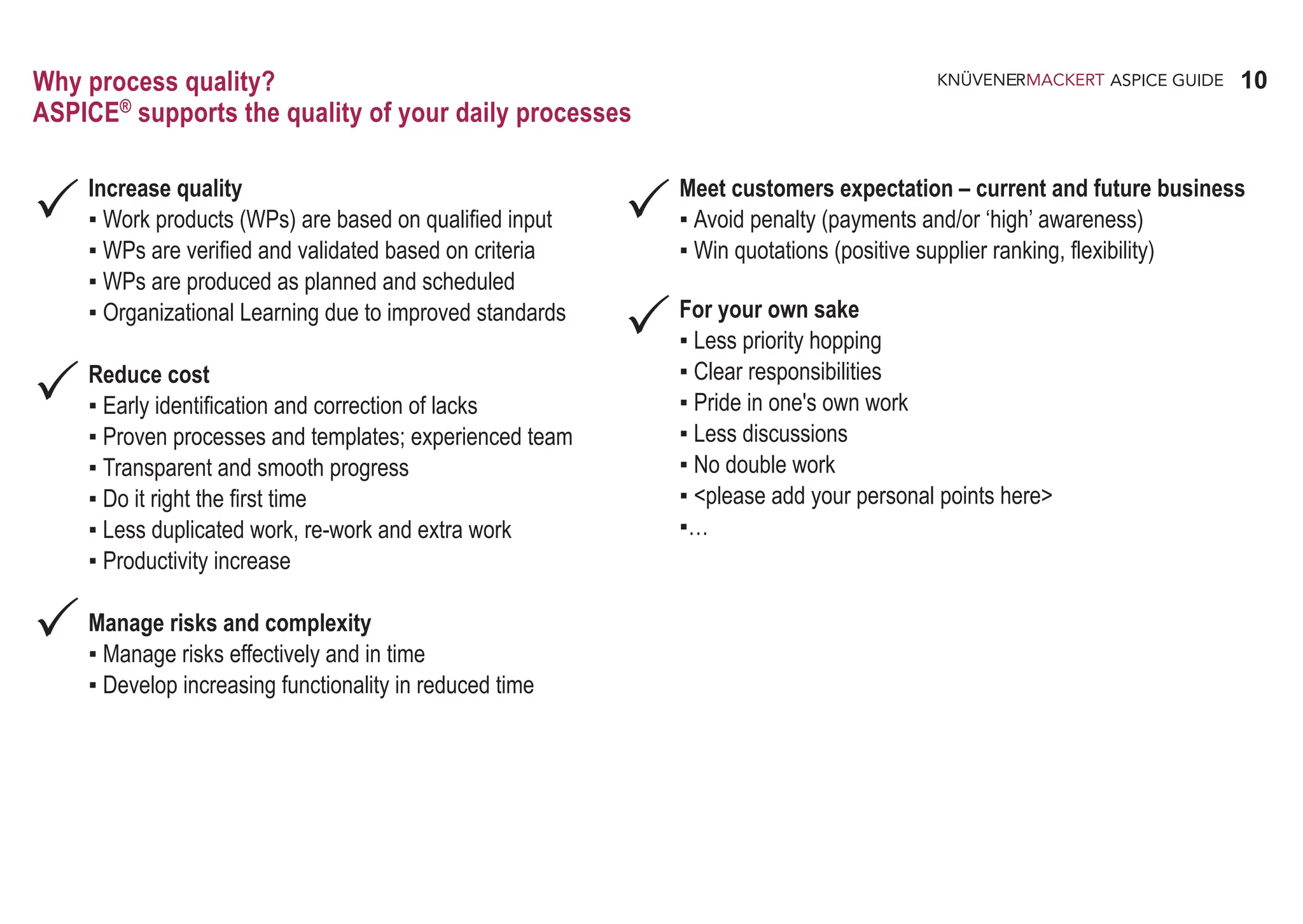
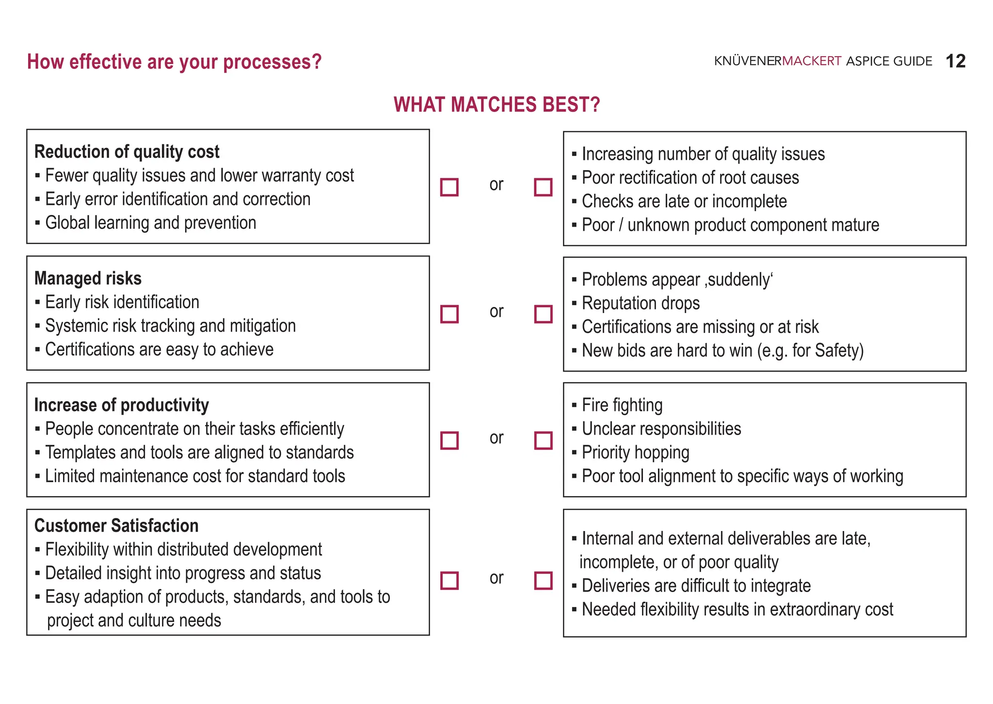
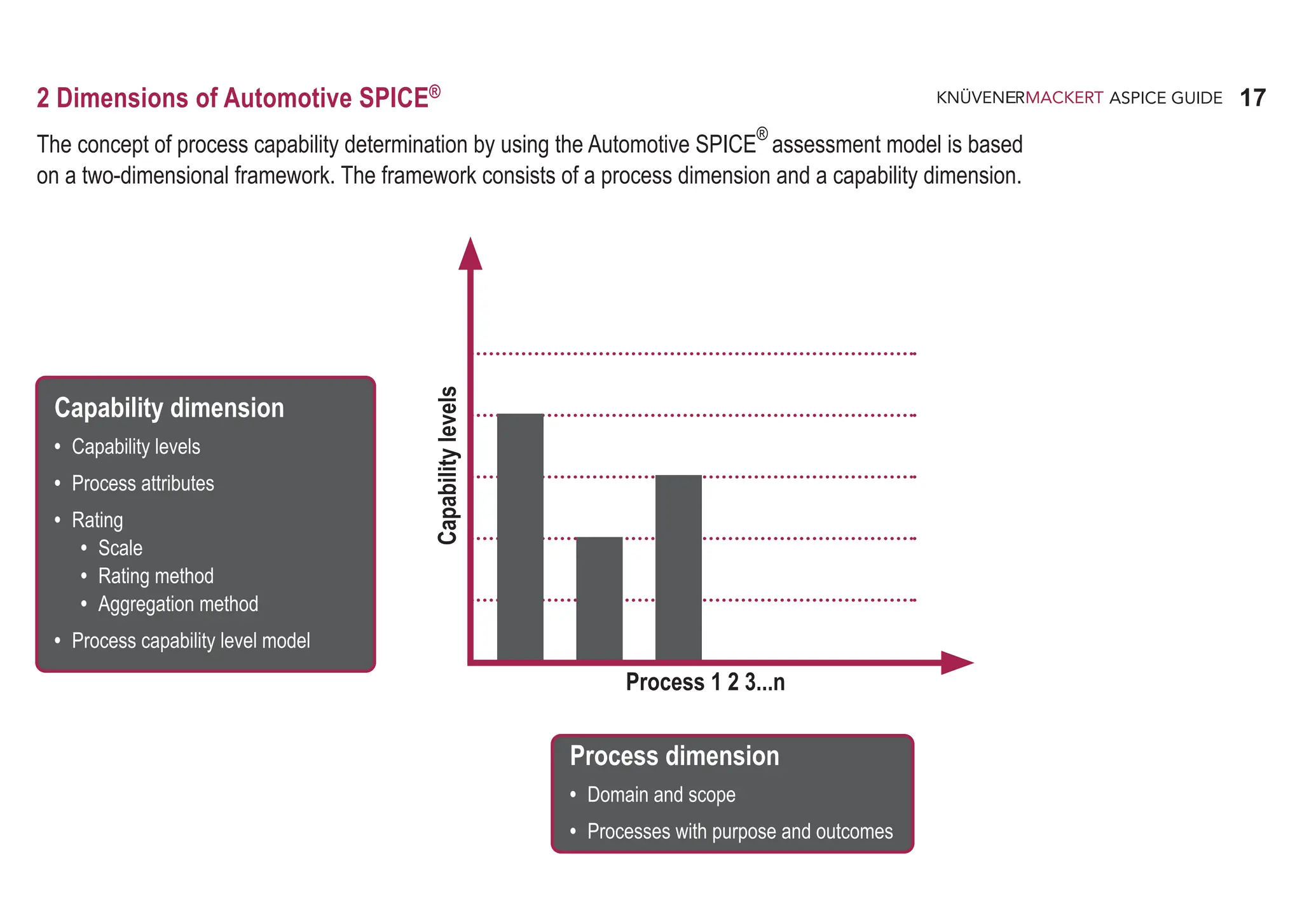
This section introduces process quality and its benefits. It explains that Automotive SPICE supports process quality by helping to:
1) Increase quality through ensuring work products are based on qualified input, verified against criteria, and produced as planned.
2) Reduce costs through early identification and correction of issues, use of proven processes and templates, and transparent progress.
3) Do it right the first time.


![8
ASPICE GUIDE
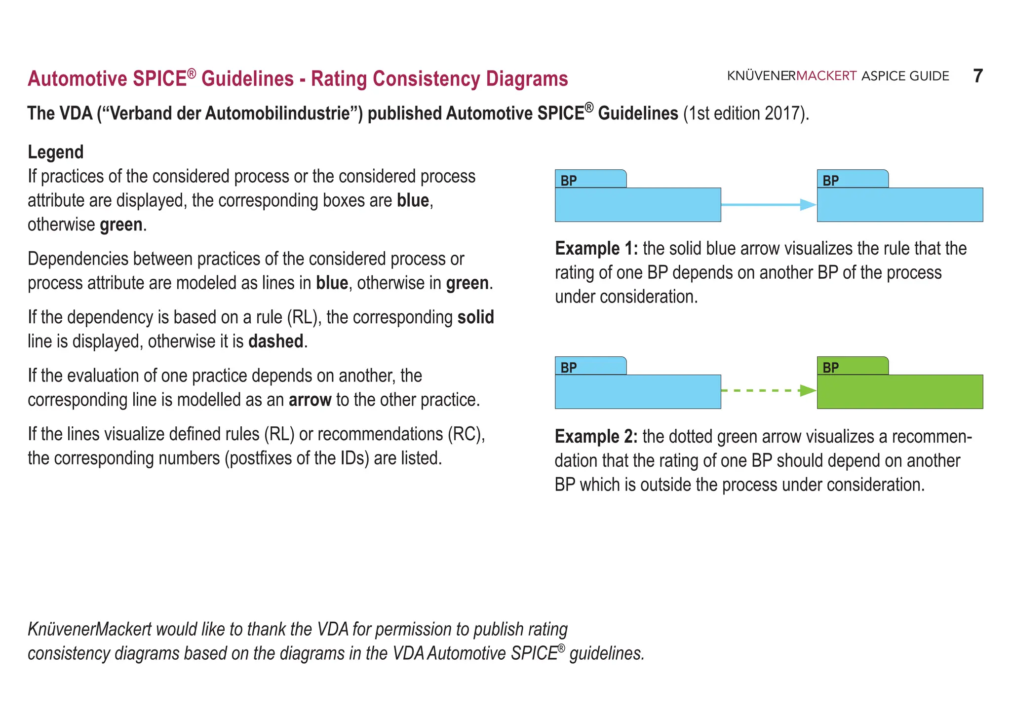
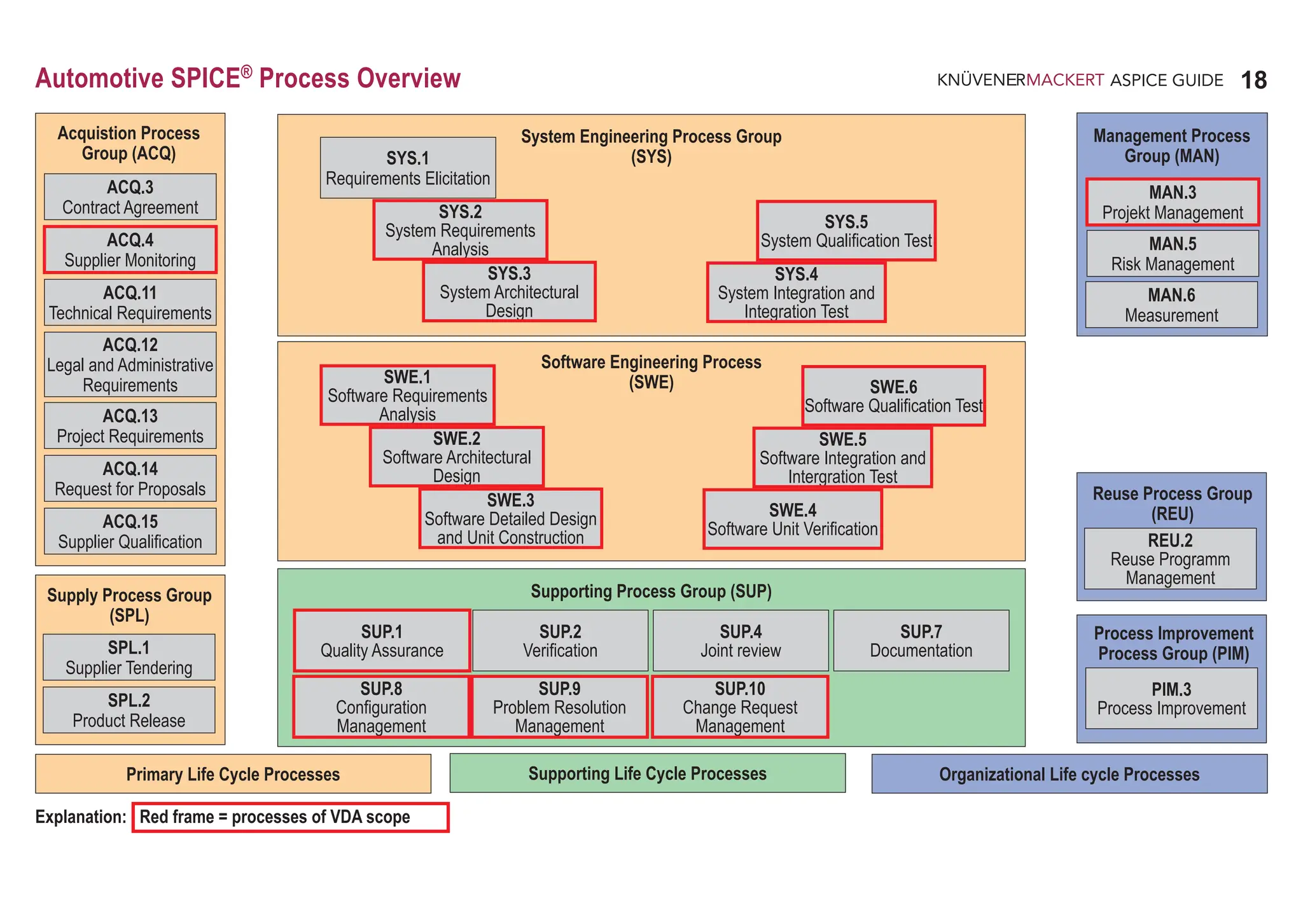
The VDA ("Verband der Automobilindustrie") has published rules and recommendations in the VDAAutomotive SPICE® Guideline
(1st edition 2017). These rules and recommendations are used as rating guidelines in an assessment. They are structured according to
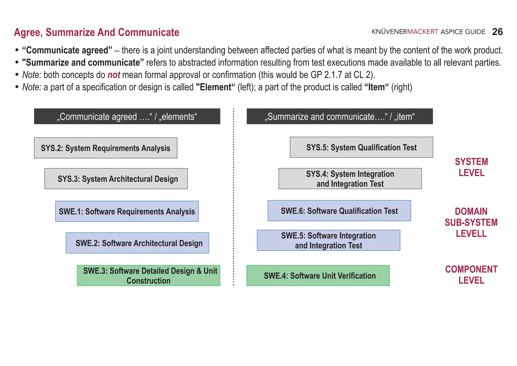
• specific terms (traceability and consistency (TAC), summarize and communicate (SAC),
verification criteria (VEC), strategy and plan (SAP)),
• application in specific environments (model-based development (MBD), agile environments (AGE),
distributed development (DID), management of third-party software (TPS),
management of platform and legacy software (PLS), application parameters (APA)),
• specific processes (VDA scope) or process attributes (level 1 to 3).
All relevant rules and recommendations for a specific practice of the VDA scope are divided into up to 6 different chapters and even
more different sections. To facilitate the overview of the rules and recommendations relevant to a practice, this ASPICE guide lists the
page numbers and IDs of the rules (RL) and recommendations (RC) under the practice, e.g., for MAN.3.BP1 on page 64 (DID.RL.1),
page 72 (PLS.RC.1) and on page 198 (MAN.3.RL.1, MAN.3.RL.2, MAN.3.RL.3, MAN.3.RC.1, MAN.3.RC.2).
Automotive SPICE®
Guidelines – Rules and Recommendations
KnüvenerMackert thanks the VDA for the permission granted to list the page numbers
and IDs of the rules and recommendations in this form following the Practices.
BP 1
Define the scope of work. Identify the project‘s goals, motivation and boundaries. [OUTCOME 1]
64: DID.RL.1
72: PLS.RC.1
198: MAN.3.RL.1-3, MAN.3.RC.1-2](https://image.slidesharecdn.com/aspice-guide-km2021-04-240204182441-58722c47/75/ASPICE-Guide-KM2021-04-pdf-8-2048.jpg)


![29
ASPICE GUIDE
To which degree is the
purpose achieved?
How to apply the process elements?
20
04-02 Domain architecture [OUTCOME 2] 13-04 Communication record [OUTCOME 7]
04-03 Domain model [OUTCOME 2] 15-07 Reuse evaluation report [OUTCOME 5, 6, 8]
08-17 Reuse plan [OUTCOME 5, 6] 15-13 Assessment/audit report [OUTCOME 3, 4]
09-03 Reuse policy [OUTCOME 1] 19-05 Reuse strategy [OUTCOME 1]
12-03 Reuse proposal [OUTCOME 4]
REU.2 Reuse Program Management
The purpose of the Reuse Program Management Process is to plan, establish, manage, control, and monitor an organization’s reuse
program and to systematically exploit reuse opportunities.
Process outcomes – as a result of successful implementation of this process
1. the reuse strategy, including its purpose, scope, goals and objectives, is defined;
2. each domain is assessed to determine its reuse potential;
3. the domains in which to investigate reuse opportunities, or in which it is intended to practice reuse, are identified;
4. the organization's systematic reuse capability is assessed;
5. reuse proposals are evaluated to ensure the reuse product is suitable for the proposed application;
6. reuse is implemented according to the reuse strategy;
7. feedback, communication, and notification mechanisms are established, that operate between affected parties; and
8. the reuse program is monitored and evaluated.
Output work products
21
BP 6
BP 4
Define organizational reuse strategy. Define the reuse program and necessary supporting infrastructure for the organization.
[Outcome 1]
Identify domains for potential reuse. Identify set(s) of systems and their components in terms of common properties that
can be organized into a collection of reusable assets that may be used to construct systems in the domain. [OUTCOME 2]
Assess domains for potential reuse. Assess each domain to identify potential use and applications of reusable components
and products. [OUTCOME 3]
Assess reuse maturity. Gain an understanding of the reuse readiness and maturity of the organization, to provide a baseline
and success criteria for reuse program management. [OUTCOME 4]
Evaluate reuse proposals. Evaluate suitability of the provided reusable components and product(s) to proposed use.
[OUTCOME 5]
Implement the reuse program. Perform the defined activities identified in the reuse program. [OUTCOME 6]
Get feedback from reuse. Establish feedback, assessment, communication and notification mechanism that operate between
affected parties to control the progress of reuse program. [OUTCOME 7, 8]
Affected parties may include reuse program administrators, asset managers, domain engineers, developers, operators,
and maintenance groups.
Monitor reuse. Monitor the implementation of the reuse program periodically and evaluate its suitability to actual needs.
[OUTCOME 6, 8]
The quality requirements for re-use work products should be defined.
REU.2 with 8 Base practices
BP 1
BP 8
BP 3
2
BP 2
BP 5
BP 7
1
… for process improvement? .... in an assessment?
What benefit does this
process offer?
What are the typical
results?
What are typical
artefacts?
What are the expected
practices to achieve
the purpose?
Do the work products
provide complete
information?
How effective is the
implementation of
these practices?
Do the outputs
provide sufficient
evidence?](https://image.slidesharecdn.com/aspice-guide-km2021-04-240204182441-58722c47/75/ASPICE-Guide-KM2021-04-pdf-29-2048.jpg)

![39
ASPICE GUIDE
08-12 Project plan [OUTCOME 1, 3, 4, 5] 14-06 Schedule [OUTCOME 3, 5]
13-04 Communication record [OUTCOME 4, 6] 14-09 Work breakdown structure [OUTCOME 3,4,5]
13-16 Change request [OUTCOME 7] 14-50 Stakeholder groups list [OUTCOME 4]
13-19 Review record [OUTCOME 2,7] 15-06 Project status report [OUTCOME 4,6]
14-02 Corrective action register [OUTCOME 7]
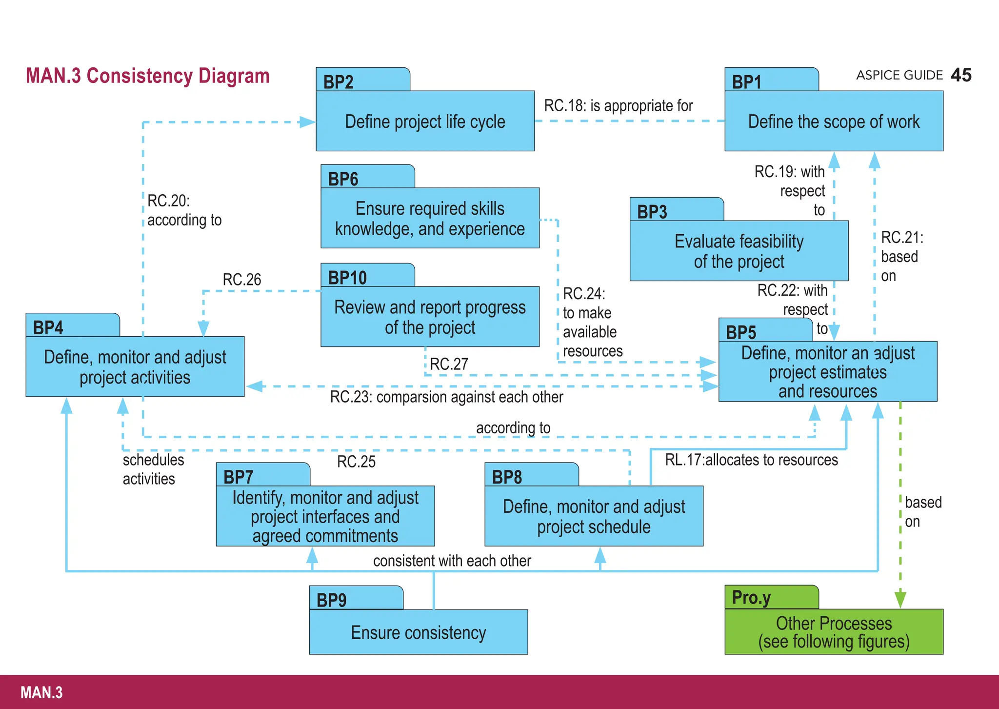
MAN.3 Project Management
The purpose of the Project Management Process is to identify, establish, and control the activities and resources necessary for a
project to produce a product, in the context of the project’s requirements and constraints.
Process outcomes – as a result of successful implementation of this process
1. the scope of the work for the project is defined;
2. the feasibility of achieving the goals of the project with available resources and constraints is evaluated;
3. the activities and resources necessary to complete the work are sized and estimated;
4. interfaces within the project, and with other projects and organizational units, are identified and monitored;
5. plans for the execution of the project are developed, implemented and maintained;
6. progress of the project is monitored and reported; and
7. corrective action is taken when project goals are not achieved, and recurrence of problems identified in the project
is prevented.
Output work products
MAN.3](https://image.slidesharecdn.com/aspice-guide-km2021-04-240204182441-58722c47/75/ASPICE-Guide-KM2021-04-pdf-39-2048.jpg)
![40
ASPICE GUIDE
MAN.3 with 10 Base practices
BP 1
BP 3
BP 2
40
Define the scope of work. Identify the project‘s goals, motivation and boundaries. [OUTCOME 1]
Define project life cycle. Define the life cycle for the project, which is appropriate to the scope, context, magnitude and
complexity of the project. [OUTCOME 2]
This typically means that the project life cycle and the customer‘s development process are consistent with each other.
Evaluate feasibility of the project. Evaluate the feasibility of achieving the goals of the project in terms of
technical feasibility within constraints with respect to time, project estimates, and available resources. [OUTCOME 2]
1
64: DID.RL.1
72: PLS.RC.1
198: MAN.3.RL.1-3, MAN.3.RC.1-2
60: AGE.RC.2
201: MAN.3.RC.11-12
208: MAN.3.RC.18
198: MAN.3.RC.2, MAN.3.RL.3
206: MAN.3.RC.15-17
208: MAN.3.RC.19
210: MAN.3.RC.30](https://image.slidesharecdn.com/aspice-guide-km2021-04-240204182441-58722c47/75/ASPICE-Guide-KM2021-04-pdf-40-2048.jpg)
![41
ASPICE GUIDE
MAN.3 with 10 Base practices
MAN.3
41
2
3
Define, monitor and adjust project activities. Define, monitor and adjust project activities and their dependencies according
to defined project life cycle and estimations. Adjust activities and their dependencies as required. [OUTCOME 3, 5, 7]
A structure and a manageable size of the activities and related work packages support an adequate progress monitoring.
Project activities typically cover engineering, management and supporting processes.
BP 4
59: AGE.RC.1
64: DID.RL.3
199: MAN.3.RC.3-5
201f: MAN.3.RC.11-13, MAN.3.RL.4-9
204: MAN.3.RL.11-15
208: MAN.3.RC.20](https://image.slidesharecdn.com/aspice-guide-km2021-04-240204182441-58722c47/75/ASPICE-Guide-KM2021-04-pdf-41-2048.jpg)
![42
ASPICE GUIDE
BP 5
Define, monitor and adjust project estimates and resources. Define, monitor and adjust project estimates of effort and
resources based on project's goals, project risks, motivation and boundaries. [OUTCOME 2, 3, 7]
Appropriate estimation methods should be used.
Examples of necessary resources are people, infrastructure (such as tools, test equipment, communication mechanis-
ms...) and hardware/materials.
Project risks (using MAN.5) and quality criteria (using SUP.1) may be considered.
Estimations and resources typically include engineering, management and supporting processes.
5
6
4
7
MAN.3 with 10 Base practices 42
61: AGE.RC.4
64: DID.RL.3
66: TPS.RC.1
68: TPS.RC.7
94: SYS.2.RC.6
125: SWE.1.RC.7
198: MAN.3.RC.2, MAN.3.RL.3
200f: MAN.3.RC.6-13, MAN.3.RL.4-9
206: MAN.3.RC.15-17
208: MAN.3.RC.21-24
209: MAN.3.RC.28
224: CL2.RC.4-6](https://image.slidesharecdn.com/aspice-guide-km2021-04-240204182441-58722c47/75/ASPICE-Guide-KM2021-04-pdf-42-2048.jpg)
![43
ASPICE GUIDE
MAN.3
MAN.3 with 10 Base practices 43
BP 6
BP 7
8
Ensure required skills, knowledge, and experience. Identify the required skills, knowledge, and experience for the
project in line with the estimates and make sure the selected individuals and teams either have or acquire these in time.
[OUTCOME 3, 7]
In the case of deviations from required skills and knowledge trainings are typically provided.
Identify, monitor and adjust project interfaces and agreed commitments. Identify and agree interfaces of the
project with other (sub-) projects, organizational units and other affected stakeholders and monitor agreed commitments.
[OUTCOME 4, 7]
Project interfaces relate to engineering, management and supporting processes.
206: MAN.3.RC.15-17
225: CL2.RC.7
70: TPS.RC.13
72: PLS.RC.3
78: APA.RC.1
201: MAN.3.RC.13, MAN.3.RL.4-9
204: MAN.3.RL.11-15
209: MAN.3.RC.29
225: CL2.RC.8
9](https://image.slidesharecdn.com/aspice-guide-km2021-04-240204182441-58722c47/75/ASPICE-Guide-KM2021-04-pdf-43-2048.jpg)
![44
ASPICE GUIDE
BP 9
BP 10
11
MAN.3 with 10 Base practices 44
BP 8 Define, monitor and adjust project schedule. Allocate resources to activities, and schedule each activity of the whole
project. The schedule has to be kept continuously updated during lifetime of the project. [OUTCOME 3, 5, 7]
This relates to all engineering, management and supporting processes.
Ensure consistency. Ensure that estimates, skills, activities, schedules, plans, interfaces, and commitments for the
project are consistent across affected parties. [OUTCOME 3, 4, 5, 7]
Review and report progress of the project. Regularly review and report the status of the project and the fulfillment of
activities against estimated effort and duration to all affected parties. Prevent recurrence of problems identified.
[OUTCOME 6, 7]
Project reviews may be executed at regular intervals by the management. At the end of a project, a project review
contributes to identifying e.g. best practices and lessons learned.
10
198: MAN.3.RC.2, MAN.3.RL.3 204: MAN.3.RL.11-15
199: MAN.3.RC.3-5 208: MAN.3.RL.17, MAN.3.RC.25
201f: MAN.3.RC.11-13, MAN.3.RL.4-9
39: TAC.RL.1 201f: MAN.3.RC.13, MAN.3.RL.4-9
59: AGE.RC.1 205: MAN.3.RC.14-5
64: DID.RL.2
43: SAC.RC.1-2
180: SUP.8.RC.9
201f: MAN.3.RC.13, MAN.3.RL.4-10
209: MAN.3.RC.26-27
210: MAN.3.RC.31](https://image.slidesharecdn.com/aspice-guide-km2021-04-240204182441-58722c47/75/ASPICE-Guide-KM2021-04-pdf-44-2048.jpg)
![46
ASPICE GUIDE
07-07 Risk measure [OUTCOME 5] 14-02 Corrective action register [OUTCOME 6]
08-14 Recovery plan [OUTCOME 4, 6] 14-08 Tracking system [OUTCOME 5, 6]
08-19 Risk management plan [OUTCOME ALL] 15-08 Risk analysis report [OUTCOME 4]
08-20 Risk mitigation plan [OUTCOME 3, 4, 5, 6] 15-09 Risk status report [OUTCOME 4, 5]
13-20 Risk action request [OUTCOME 1, 2, 6]
MAN.5 Risk Management
The purpose of the Risk Management Process is to identify, analyze, treat and monitor the risks continuously.
Process outcomes – as a result of successful implementation of this process
1. the scope of the risk management to be performed is determined;
2. appropriate risk management strategies are defined and implemented;
3. risks are identified as they develop during the conduct of the project;
4. risks are analyzed and the priority in which to apply resources to treatment of these risks is determined;
5. risk measures are defined, applied, and assessed to determine changes in the status of risk and the progress of the treatment
activities; and
6. appropriate treatment is taken to correct or avoid the impact of risk based on its priority, probability, and consequence or other
defined risk threshold.
Output work products
Establish risk management scope. Determine the scope of risk management to be performed for the project, in accordance
with organizational risk management policies. [OUTCOME 1]
Risks may include technical, economic and timing risks.
MAN.5 with 7 Base practices
BP 1
1](https://image.slidesharecdn.com/aspice-guide-km2021-04-240204182441-58722c47/75/ASPICE-Guide-KM2021-04-pdf-46-2048.jpg)
![47
ASPICE GUIDE
BP 5
Define risk management strategies. Define appropriate strategies to identify risks, mitigate risks and set acceptability
levels for each risk or set of risks, both at the project and organizational level. [OUTCOME 2]
Identify risks. Identify risks to the project both initially within the project strategy and as they develop during the conduct
of the project, continuously looking for risk factors at any occurrence of technical or managerial decisions. [OUTCOME 2, 3]
Examples of risk areas that are typically analyzed for potential risk reasons or risks factors include: cost, schedule, effort,
resource, and technical.
Examples of risk factors may include: unsolved and solved trade-offs, decisions of not implementing a project feature,
design changes, lack of expected resources.
Analyze risks. Analyze risks to determine the priority in which to apply resources to mitigate these risks. [OUTCOME 4]
Risks are normally analyzed to determine their probability, consequence and severity.
Different techniques may be used to analyze a system in order to understand if risks exist, for example,
functional analysis, simulation, FMEA, FTA etc.
Define risk treatment actions. For each risk (or set of risks) define, perform and track the selected actions to keep/reduce
the risks to acceptable level. [OUTCOME 5, 6]
Monitor risks. For each risk (or set of risks) define measures (e.g. metrics) to determine changes in the status of a risk and to
evaluate the progress of the mitigation activities. Apply and assess these risk measures. [OUTCOME 5, 6]
Major risks may need to be communicated to and monitored by higher levels of management.
Take corrective action. When expected progress in risk mitigation is not achieved, take appropriate corrective action to
reduce or avoid the impact of risk. [OUTCOME 6]
Corrective actions may involve developing and implementing new mitigation strategies or adjusting the existing strategies.
MAN.5 with 7 Base practices
BP 2
2
BP 4
BP 6
BP 3
3
4
5
6
7
BP7
47
MAN.5](https://image.slidesharecdn.com/aspice-guide-km2021-04-240204182441-58722c47/75/ASPICE-Guide-KM2021-04-pdf-47-2048.jpg)
![48
ASPICE GUIDE
04-02 Domain architecture [OUTCOME 2] 13-04 Communication record [OUTCOME 7]
04-03 Domain model [OUTCOME 2] 15-07 Reuse evaluation report [OUTCOME 5, 6, 8]
08-17 Reuse plan [OUTCOME 5, 6] 15-13 Assessment/audit report [OUTCOME 3, 4]
09-03 Reuse policy [OUTCOME 1] 19-05 Reuse strategy [OUTCOME 1]
12-03 Reuse proposal [OUTCOME 4]
REU.2 Reuse Program Management
The purpose of the Reuse Program Management Process is to plan, establish, manage, control, and monitor an organization’s reuse
program and to systematically exploit reuse opportunities.
Process outcomes – as a result of successful implementation of this process
1. the reuse strategy, including its purpose, scope, goals and objectives, is defined;
2. each domain is assessed to determine its reuse potential;
3. the domains in which to investigate reuse opportunities, or in which it is intended to practice reuse, are identified;
4. the organization's systematic reuse capability is assessed;
5. reuse proposals are evaluated to ensure the reuse product is suitable for the proposed application;
6. reuse is implemented according to the reuse strategy;
7. feedback, communication, and notification mechanisms are established, that operate between affected parties; and
8. the reuse program is monitored and evaluated.
Output work products](https://image.slidesharecdn.com/aspice-guide-km2021-04-240204182441-58722c47/75/ASPICE-Guide-KM2021-04-pdf-48-2048.jpg)
![49
ASPICE GUIDE
BP 6
BP 4
Define organizational reuse strategy. Define the reuse program and necessary supporting infrastructure for the organization.
[Outcome 1]
Identify domains for potential reuse. Identify set(s) of systems and their components in terms of common properties that
can be organized into a collection of reusable assets that may be used to construct systems in the domain. [OUTCOME 2]
Assess domains for potential reuse. Assess each domain to identify potential use and applications of reusable components
and products. [OUTCOME 3]
Assess reuse maturity. Gain an understanding of the reuse readiness and maturity of the organization, to provide a baseline
and success criteria for reuse program management. [OUTCOME 4]
Evaluate reuse proposals. Evaluate suitability of the provided reusable components and product(s) to proposed use.
[OUTCOME 5]
Implement the reuse program. Perform the defined activities identified in the reuse program. [OUTCOME 6]
Get feedback from reuse. Establish feedback, assessment, communication and notification mechanism that operate between
affected parties to control the progress of reuse program. [OUTCOME 7, 8]
Affected parties may include reuse program administrators, asset managers, domain engineers, developers, operators,
and maintenance groups.
Monitor reuse. Monitor the implementation of the reuse program periodically and evaluate its suitability to actual needs.
[OUTCOME 6, 8]
The quality requirements for re-use work products should be defined.
REU.2 with 8 Base practices
BP 1
BP 8
BP 3
2
BP 2
BP 5
BP 7
1
49
REU.2](https://image.slidesharecdn.com/aspice-guide-km2021-04-240204182441-58722c47/75/ASPICE-Guide-KM2021-04-pdf-49-2048.jpg)
![50
ASPICE GUIDE
02-01 Commitment/agreement [OUTCOME 4] 13-16 Change request [OUTCOME 4]
13-01 Acceptance record [OUTCOME 3] 13-19 Review record [OUTCOME 2]
13-04 Communication record [OUTCOME 1, 2] 14-02 Corrective action register [OUTCOME 4]
13-09 Meeting support record [OUTCOME 1] 15-01 Analysis report [OUTCOME 3]
13-14 Progress status record [OUTCOME 2]
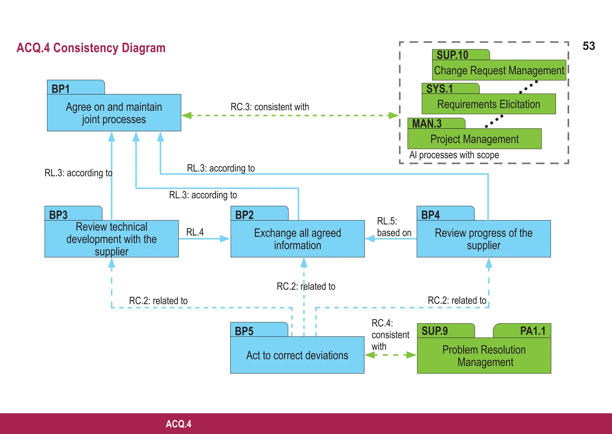
ACQ.4 Supplier Monitoring
The purpose of the Supplier Monitoring Process is to track and assess the performance of the supplier against agreed
requirements.
Process outcomes – as a result of successful implementation of this process
1. joint activities, as agreed between the customer and the supplier, are performed as needed;
2. all information, agreed upon for exchange, is communicated regularly between the supplier and customer;
3. performance of the supplier is monitored against the agreements; and
4. changes to the agreement, if needed, are negotiated between the customer and the supplier and documented in the agreement.
Output work products](https://image.slidesharecdn.com/aspice-guide-km2021-04-240204182441-58722c47/75/ASPICE-Guide-KM2021-04-pdf-50-2048.jpg)
![51
ASPICE GUIDE
ACQ.4 with 5 Base practices
BP 1
1
2
3
BP 2
4
51
ACQ.4
Agree on and maintain joint processes, joint interfaces, and information to be exchanged. Establish and maintain an
agreement on information to be exchanged and on joint processes and joint interfaces, responsibilities, type and frequency
of joint activities, communications, meetings, status reports and reviews. [OUTCOME 1, 2, 4]
Joint processes and interfaces usually include project management, requirements management, change
management, configuration management, problem resolution, quality assurance and customer acceptance.
Joint activities to be performed should be mutually agreed between the customer and the supplier.
The term customer in this process refers to the assessed party. The term supplier refers to the supplier of
the assessed party.
Exchange all agreed information. Use the defined joint interfaces between customer and supplier for the exchange of all
agreed information. [OUTCOME 1, 2, 3]
Agreed information should include all relevant work products.
69f: TPS.RC.8-11, 13
83: ACQ.4.RL.2
84: ACQ.4.RC.1
86: ACQ.4.RC.3
43: SAC.RC.1-2
67: TPS.RC.2-3
85: ACQ.4.RL.3](https://image.slidesharecdn.com/aspice-guide-km2021-04-240204182441-58722c47/75/ASPICE-Guide-KM2021-04-pdf-51-2048.jpg)
![52
ASPICE GUIDE
BP 3
BP 4
BP 5
Review technical development with the supplier. Review development with the supplier on the agreed regular basis,
covering technical aspects, problems and risks and also track open items to closure. [OUTCOME 1, 3, 4]
Review progress of the supplier. Review progress of the supplier regarding schedule, quality, and cost on the agreed
regular basis. Track open items to closure and perform risk mitigation activities. [OUTCOME 1, 3, 4]
Act to correct deviations. Take action when agreed objectives are not achieved to correct deviations from the agreed
project plans and to prevent reoccurrence of problems identified. Negotiate changes to objectives and document them in
the agreements. [OUTCOME 4]
ACQ.4 with 5 Base practices
85f: ACQ.4.RL.3-4
70: TPS.RC.12
85: ACQ.4.RL.3
86: ACQ.4.RL.5
86: ACQ.4.RC.2
52](https://image.slidesharecdn.com/aspice-guide-km2021-04-240204182441-58722c47/75/ASPICE-Guide-KM2021-04-pdf-52-2048.jpg)
![54
ASPICE GUIDE
08-13 Quality plan [OUTCOME 1,2] 13-19 Review record [OUTCOME 2, 3, 4]
13-04 Communication record [OUTCOME 3, 4, 5] 14-02 Corrective action register [OUTCOME 3, 5, 6]
13-07 Problem record [OUTCOME 3, 5] 18-07 Quality criteria [OUTCOME 1]
13-18 Quality record [OUTCOME 2, 3, 4]
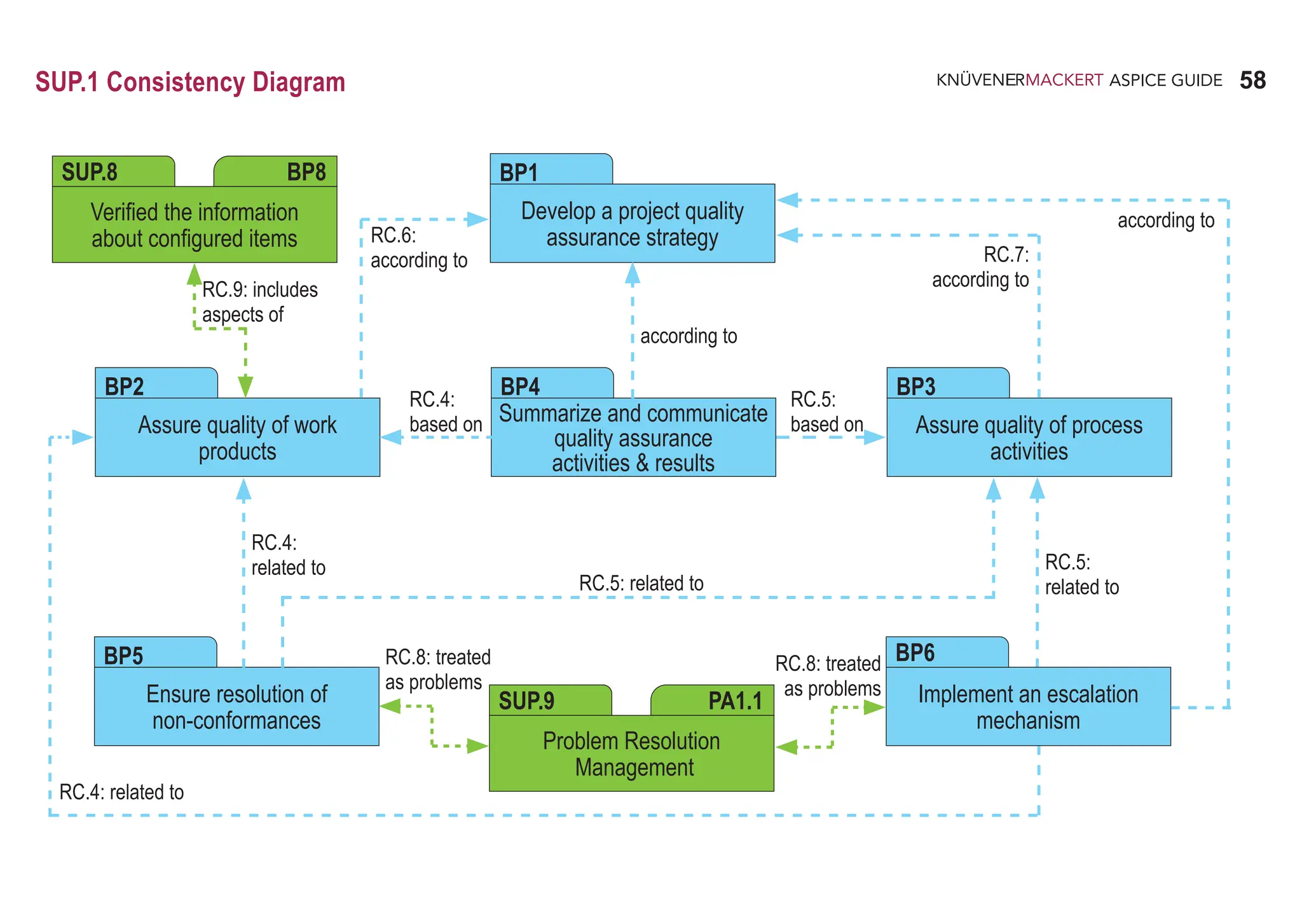
SUP.1 Quality Assurance
The purpose of the Quality Assurance Process is to provide independent and objective assurance that work products and processes
comply with predefined provisions and plans and that non-conformances are resolved and further prevented.
Process outcomes – as a result of successful implementation of this process
1. a strategy for performing quality assurance is developed, implemented, and maintained;
2. quality assurance is performed independently and objectively without conflicts of interest;
3. non-conformances of work products, processes, and process activities with relevant requirements are identified, recorded,
communicated to the relevant parties, tracked, resolved, and further prevented;
4. conformance of work products, processes and activities with relevant requirements is verified, documented, and communicated
to the relevant parties;
5. authority to escalate non-conformances to appropriate levels of management is established; and
6. management ensures that escalated non-conformances are resolved.
Output work products](https://image.slidesharecdn.com/aspice-guide-km2021-04-240204182441-58722c47/75/ASPICE-Guide-KM2021-04-pdf-54-2048.jpg)
![55
ASPICE GUIDE
SUP.1 with 6 Base practices
BP 1
1
2
3
4
55
SUP.1
Develop a project quality assurance strategy. Develop a strategy in order to ensure that work product and process
quality assurance is performed at project level independently and objectively without conflicts of interest. [OUTCOME 1, 2]
Aspects of independence may be financial and/or organizational structure.
Quality assurance may be coordinated with, and make use of, the results of other processes such as verification,
validation, joint review, audit and problem management.
Process quality assurance may include process assessments and audits, problem analysis, regular check of methods,
tools, documents and the adherence to defined processes, reports and lessons learned that improve processes for
future projects.
Work product quality assurance may include reviews, problem analysis, reports and lessons learned that improve
the work products for further use.
51ff: SAP.RL.1-4
62: AGE.RC.10
165ff: SUP.1.RL.1-5
167f: SUP.1.RC.1-2
232: CL2.RC.12](https://image.slidesharecdn.com/aspice-guide-km2021-04-240204182441-58722c47/75/ASPICE-Guide-KM2021-04-pdf-55-2048.jpg)
![56
ASPICE GUIDE
BP 2
SUP.1 with 6 Base practices 56
5
6
BP3
7
8
Assure quality of work products. Perform the activities according to the quality assurance strategy and the project
schedule to ensure that the work products meet the defined work product requirements and document the results.
[OUTCOME 2, 3, 4]
Relevant work product requirements may include requirements from applicable standards.
Non-conformances detected in work products may be entered into the problem resolution management process
(SUP.9) to document, analyze, resolve, track to closure and prevent the problems.
Assure quality of process activities. Perform the activities according to the quality assurance strategy and the project
schedule to ensure that the processes meet their defined goals and document the results. [OUTCOME 2, 3, 4]
Relevant process goals may include goals from applicable standards.
Problems detected in the process definition or implementation may be entered into a process improvement process
(PIM.3) to describe, record, analyze, resolve, track to closure and prevent the problems.
167f: SUP.1.RL.6-7
170: SUP.1.RC.3
171: SUP.1.RC.7
62: AGE.RC.11
79: APA.RL.7
167f: SUP.1.RL.6-7
170: SUP.1.RC.3
171: SUP.1.RC.6
172: SUP.1.RC.9
233: CL2.RC.17](https://image.slidesharecdn.com/aspice-guide-km2021-04-240204182441-58722c47/75/ASPICE-Guide-KM2021-04-pdf-56-2048.jpg)
![57
ASPICE GUIDE
SUP.1
BP 4
SUP.1 with 6 Base practices
Summarize and communicate quality assurance activities and results. Regularly report performance, deviations, and
trends of quality assurance activities to relevant parties for information and action according to the quality assurance strategy.
[OUTCOME 3, 4]
Ensure resolution of non-conformances. Deviations or non-conformance found in process and product quality assurance
activities should be analyzed, tracked, corrected, and further prevented. [OUTCOME 3,6]
Implement an escalation mechanism. Establish and maintain an escalation mechanism according to the quality assurance
strategy that ensures that quality assurance may escalate problems to appropriate levels of management and other relevant
stakeholders to resolve them. [OUTCOME 5, 6]
BP 5
BP 6
57
43: SAC.RC.1-2
171: SUP.1.RC.4-5
168f: SUP.1.RL.8-9
171: SUP.1.RC.4-5
172: SUP.1.RC.8
65: DID.RL.9
171: SUP.1.RC.4-5
172: SUP.1.RC.8](https://image.slidesharecdn.com/aspice-guide-km2021-04-240204182441-58722c47/75/ASPICE-Guide-KM2021-04-pdf-57-2048.jpg)

![60
ASPICE GUIDE
13-04 Communication record [OUTCOME 5] 14-02 Corrective action register [OUTCOME 4]
13-07 Problem record [OUTCOME 3, 4, 5] 18-07 Quality criteria [OUTCOME 2]
13-25 Verification results [OUTCOME 2, 3, 4, 5] 19-10 Verification strategy [OUTCOME 1]
SUP.2 Verification
The purpose of the Verification Process is to confirm that each work product of a process or project properly reflects the specified
requirements.
Process outcomes – as a result of successful implementation of this process
1. a verification strategy is developed, implemented and maintained;
2. criteria for verification of all required work products are identified;
3. required verification activities are performed;
4. defects are identified, recorded and tracked; and
5. results of the verification activities are made available to the customer and other involved parties.
Output work products](https://image.slidesharecdn.com/aspice-guide-km2021-04-240204182441-58722c47/75/ASPICE-Guide-KM2021-04-pdf-60-2048.jpg)
![61
ASPICE GUIDE
BP 3
SUP.2 with 5 Base practices
Develop a verification strategy. Develop and implement a verification strategy, including verification activities with associated
methods, techniques, and tools; work product or processes under verification; degrees of independence for verification and
schedule for performing these activities. [OUTCOME 1]
Verification strategy is implemented through a plan.
Software and system verification may provide objective evidence that the outputs of a particular phase of the software
development life cycle (e.g. requirements, design, implementation, testing) meet all of the specified requirements for
that phase.
Verification methods and techniques may include inspections, peer reviews (see also SUP.4), audits, walkthroughs
and analysis.
Develop criteria for verification. Develop the criteria for verification of all required technical work products. [OUTCOME 2]
Conduct verification. Verify identified work products according to the specified strategy and to the developed criteria to con-
firm that the work products meet their specified requirements. The results of verification activities are recorded. [OUTCOME 3]
Determine and track actions for verification results. Problems identified by the verification should be entered into the
problem resolution management process (SUP.9) to describe, record, analyze, resolve, track to closure and prevent the
problems. [OUTCOME 4]
Report verification results. Verification results should be reported to all affected parties. [OUTCOME 5]
BP 1
1
2
BP 2
BP 4
3
BP 5
61
SUP.2](https://image.slidesharecdn.com/aspice-guide-km2021-04-240204182441-58722c47/75/ASPICE-Guide-KM2021-04-pdf-61-2048.jpg)
![62
ASPICE GUIDE
SUP.4 Joint Review
The purpose of the Joint review process is to maintain a common understanding with the stakeholders of the progress against
the objectives of the agreement and what should be done to help ensure development of a product that satisfies the stakeholders.
Joint reviews are at both project management and technical levels and are held throughout the life of the project.
Process outcomes – as a result of successful implementation of this process
1. management and technical reviews are held based on the needs of the project;
2. the status and products of an activity of a process are evaluated through joint review activities between the stakeholders;
3. review results are made known to all affected parties;
4. action items resulting from reviews are tracked to closure; and
5. problems are identified and recorded.
Joint review should be performed at specific milestones during project/product development. The scope and the goals of joint review
may be different depending on project/product development phase (for example, in the early stage of a project joint review may be
„conceptual“ in order to analyze the customer requirements; in later stages joint review may be concerned with the implementation).
Joint review should be performed to verify different aspects (for example: hardware resources utilization; the introduction of new
requirements and new technologies; modification to the working team structure; technology changes).
1
2
13-04 Communication record [OUTCOME 3] 14-02 Corrective action register [OUTCOME 3, 4, 5]
13-05 Contract review record [OUTCOME 1, 2, 3] 14-08 Tracking system [OUTCOME 3, 4, 5]
13-07 Problem record [OUTCOME 3, 5] 15-01 Analysis report [OUTCOME 3, 5]
13-09 Meeting support record [OUTCOME 1,2] 15-13 Assessment/audit report [OUTCOME 1,2]
13-19 Review record [OUTCOME ALL] 15-16 Improvement opportunity [OUTCOME 3, 4]
Output work products](https://image.slidesharecdn.com/aspice-guide-km2021-04-240204182441-58722c47/75/ASPICE-Guide-KM2021-04-pdf-62-2048.jpg)
![63
ASPICE GUIDE
BP 3
SUP.4 with 8 Base practices
Define review elements. Based on the needs of the project, identify the schedule, scope and participants of management
and technical reviews, agree all resources required to conduct the reviews (this includes personnel, location and facilities)
and establish review criteria for problem identification, resolution and agreement. [OUTCOME 1]
Establish a mechanism to handle review outcomes. Establish mechanisms to ensure that review results are made
available to all affected parties that problems detected during the reviews are identified and recorded and that action items
raised are recorded for action. [OUTCOME 3]
Prepare joint review. Collect, plan, prepare and distribute review material as appropriate in preparation for the review.
[OUTCOME 1]
The following items may be addressed: Scope and purpose of the review; Products and problems to be reviewed;
Entry and exit criteria; Meeting agenda; Roles and participants; Distribution list; Responsibilities; Resource and facility
requirements; Used tools (checklists, scenario for perspective based reviews etc.).
Conduct joint reviews. Conduct joint management and technical reviews as planned. Record the review results.
[OUTCOME 1, 2]
Distribute the results. Document and distribute the review results to all the affected parties. [OUTCOME 3]
Determine actions for review results. Analyze the review results, propose actions for resolution and determine the priority
for actions. [OUTCOME 4]
BP 1
BP 2
BP 4
1
BP 5
BP 6
63
SUP.4](https://image.slidesharecdn.com/aspice-guide-km2021-04-240204182441-58722c47/75/ASPICE-Guide-KM2021-04-pdf-63-2048.jpg)
![64
ASPICE GUIDE
SUP.4 with 8 Base practices
Track actions for review results. Track actions for resolution of identified problems in a review to closure. [OUTCOME 4]
Identify and record problems. Identify and record the problems detected during the reviews according to the established
mechanism. [OUTCOME 5]
BP 7
BP 8
64](https://image.slidesharecdn.com/aspice-guide-km2021-04-240204182441-58722c47/75/ASPICE-Guide-KM2021-04-pdf-64-2048.jpg)

![66
ASPICE GUIDE
08-26 Documentation plan [OUTCOME 1,2] 14-01 Change history [OUTCOME 5, 6]
13-01 Acceptance record [OUTCOME 4, 5] 14-11 Work product list [OUTCOME 3]
13-19 Review record [OUTCOME 4, 5]
SUP.7 Documentation
The purpose of the Documentation Process is to develop and maintain the recorded information produced by a process.
Process outcomes – as a result of successful implementation of this process
1. a strategy identifying the documentation to be produced during the life cycle of the product or service is developed;
2. the standards to be applied for the development of the documentation are identified;
3. documentation to be produced by the process or project is identified;
4. the content and purpose of all documentation is specified, reviewed and approved;
5. documentation is developed and made available in accordance with identified standards; and
6. documentation is maintained in accordance with defined criteria.
Output work products
SUP.7 with 8 Base practices
Develop a documentation management strategy. Develop a documentation management strategy which addresses
where, when and what should be documented during the life cycle of the product/service.[OUTCOME 1]
A documentation management strategy may define the controls needed to approve documentation for adequacy prior to
issue; to review and update as necessary and re-approve documentation; to ensure that changes and the current revision
status of documentation are identified; to ensure that relevant versions of documentation are available at points of issue;
to ensure that documentation remain legible and readily identifiable; to ensure the controlled distribution of documentation;
to prevent unintended use of obsolete documentation ; and may also specify the levels of confidentiality, copyright or
disclaimers of liability for the documentation.
BP 1
1](https://image.slidesharecdn.com/aspice-guide-km2021-04-240204182441-58722c47/75/ASPICE-Guide-KM2021-04-pdf-66-2048.jpg)
![67
ASPICE GUIDE
BP 8
SUP.7 with 8 Base practices
Establish standards for documentation. Establish standards for developing, modifying and maintaining documentation.
[OUTCOME 2]
Specify documentation requirements. Specify requirements for documentation such as title, date, identifier, version history,
author(s), reviewer, authorizer, outline of contents, purpose, and distribution list. [OUTCOME 2]
Identify the relevant documentation to be produced. For any given development life cycle, identify the documentation
to be produced. [OUTCOME 3]
Develop documentation. Develop documentation at required process points according to established standards and policy,
ensuring the content and purpose is reviewed and approved as appropriate. [OUTCOME 4, 5]
Check documentation. Review documentation before distribution, and authorize documentation as appropriate before
distribution or release. [OUTCOME 5]
The documentation intended for use by system and software users should accurately describe the system and software
and how it is to be used in clear and useful manner for them.
Documentation should be checked through verification or validation process.
Distribute documentation. Distribute documentation according to determined modes of distribution via appropriate media
to all affected parties, confirming delivery of documentation, where necessary. [OUTCOME 5]
Maintain documentation. Maintain documentation in accordance with the determined documentation strategy. [OUTCOME 6]
If the documentation is part of a product baseline or if its control and stability are important, it should be modified and
distributed in accordance with process SUP.8 Configuration management.
BP 2
BP 3
BP 4
3
BP 5
BP 6
2
BP 7
4
67
SUP.7](https://image.slidesharecdn.com/aspice-guide-km2021-04-240204182441-58722c47/75/ASPICE-Guide-KM2021-04-pdf-67-2048.jpg)
![68
ASPICE GUIDE
06-02 Handling and storage guide [OUTCOME 3, 4, 5, 7] 13-10 Configuration management record [OUTCOME 2, 5, 7]]
08-04 Configuration management [OUTCOME 1, 2, 7] 14-01 Change history [OUTCOME 3]
08-14 Recovery plan [OUTCOME 1,7] 16-03 Configuration management system [OUTCOME 1, 3, 4]
13-08 Baseline [OUTCOME 2, 3, 4, 5, 6]
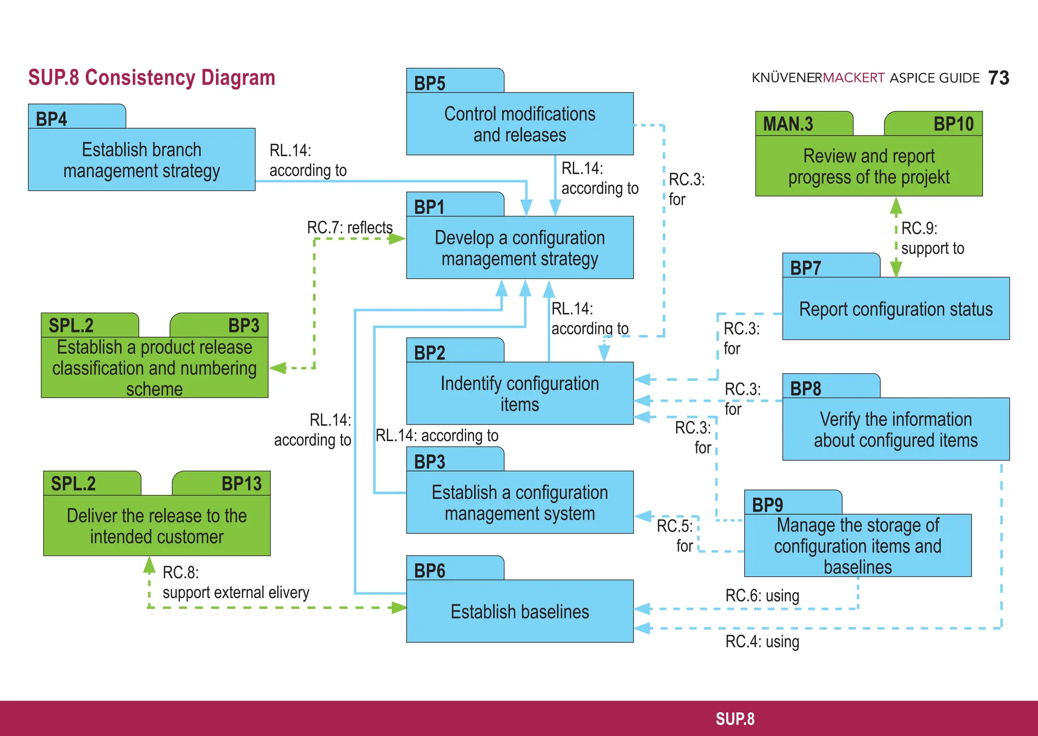
SUP.8 Configuration Management
The purpose of the Configuration Management Process is to establish and maintain the integrity of all work products of a process
or project and make them available to affected parties.
Process outcomes – as a result of successful implementation of this process
1. a configuration management strategy is developed;
2. all configuration items generated by a process or project are identified, defined and baselined according to the configuration
management strategy;
3. modifications and releases of the configuration items are controlled;
4. modifications and releases are made available to affected parties;
5. the status of the configuration items and modifications is recorded and reported;
6. the completeness and consistency of the baselines is ensured; and
7. storage of the configuration items is controlled.
Output work products](https://image.slidesharecdn.com/aspice-guide-km2021-04-240204182441-58722c47/75/ASPICE-Guide-KM2021-04-pdf-68-2048.jpg)
![69
ASPICE GUIDE
SUP.8 with 9 Base practices
Develop a configuration management strategy. Develop a configuration management strategy, including
• responsibilities;
• tools and repositories;
• criteria for configuration items;
• naming conventions;
• access rights;
• criteria for baselines;
• merge and branch strategy;
• the revision history approach for configuration items [OUTCOME 1]
The configuration management strategy typically supports the handling of product/software variants which may be
caused by different sets of application parameters or by other causes.
The branch management strategy specifies in which cases branching is permissible, whether authorization is required,
how branches are merged, and which activities are required to verify that all changes have been consistently integrated
without damage to other changes or to the original software.
BP 1
2
1
69
SUP.8
51ff: SAP.RL.1-4
174: SUP.8.RL.1-5
175: SUP.8.RC.1](https://image.slidesharecdn.com/aspice-guide-km2021-04-240204182441-58722c47/75/ASPICE-Guide-KM2021-04-pdf-69-2048.jpg)
![70
ASPICE GUIDE
SUP.8 with 9 Base practices
Identify configuration items. Identify and document configuration items according to the configuration management strategy.
[OUTCOME 2]
Configuration control is typically applied for the products that are delivered to the customer, designated internal work pro-
ducts, acquired products, tools and other configuration items that are used in creating and describing these work products.
Establish a configuration management system. Establish a configuration management system according to the
configuration management strategy. [OUTCOME 1, 2, 3, 4, 6, 7]
Establish branch management. Establish branch management according to the configuration management strategy where
applicable for parallel developments that use the same base. [OUTCOME 1, 3, 4, 6, 7]
Control modifications and releases. Establish mechanisms for control of the configuration items according to the
configuration management strategy, and control modifications and releases using these mechanisms. [OUTCOME 3, 4, 5]
BP 3
3
BP 2
70
BP 4
BP 5
78: APA.RL.4
179: SUP.8.RL.14
232: CL2.RC.13
177f: SUP.8.RL.11-14
233: CL2.RC.15
176: SUP.8.RL.9-10
179: SUP.8.RL.14
179: SUP.8.RL.14, SUP.8.RC.3
233: CL2.RC.15](https://image.slidesharecdn.com/aspice-guide-km2021-04-240204182441-58722c47/75/ASPICE-Guide-KM2021-04-pdf-70-2048.jpg)
![71
ASPICE GUIDE
SUP.8
Establish baselines. Establish baselines for internal purposes and for external delivery according to the configuration
management strategy. [OUTCOME 2]
For baseline issues refer also to the product release process SPL.2.
Report configuration status. Record and report status of configuration items to support project management and other
relevant processes. [OUTCOME 5]
Regular reporting of the configuration status (e.g. how many configuration items are currently under work, checked in,
tested, released, etc.) supports project management activities and dedicated project phases like software integration.
Verify the information about configured items. Verify that the information about configured items, and their baselines is
complete and ensure the consistency of baselines. [OUTCOME 6]
A typical implementation is performing baseline and configuration management audits.
SUP.8 with 9 Base practices 71
BP 6
4
BP 7
5
175: SUP.8.RL.6-8
176: SUP.8.RC.2
179: SUP.8.RL.14
233: CL2.RC.15
179: SUP.8.RC.3
BP 8
6
175: SUP.8.RL.6-8
176: SUP.8.RC.2, SUP.8.RL.9-10
179: SUP.8.RC.3-4
233: CL2.RC.18](https://image.slidesharecdn.com/aspice-guide-km2021-04-240204182441-58722c47/75/ASPICE-Guide-KM2021-04-pdf-71-2048.jpg)
![72
ASPICE GUIDE
Manage the storage of configuration items and baselines. Ensure the integrity and availability of configuration items
and baselines through appropriate scheduling and resourcing of storage, archiving (long term storage) and backup of the
used CM systems. [OUTCOME 4, 5, 6, 7]
Backup, storage and archiving may need to extend beyond the guaranteed lifetime of available storage media. Relevant
configuration items affected may include those referenced in and . Availability may be specified by contract
requirements.
7
BP9
2 3
SUP.8 with 9 Base practices 72
177: SUP.8.RL.11-13
179: SUP.8.RC.3, 5-6](https://image.slidesharecdn.com/aspice-guide-km2021-04-240204182441-58722c47/75/ASPICE-Guide-KM2021-04-pdf-72-2048.jpg)
![74
ASPICE GUIDE
08-27 Problem management plan [OUTCOME 1] 15-05 Evaluation report [OUTCOME 3]
13-07 Problem record [OUTCOME 2, 3, 4, 5] 15-12 Problem status report [OUTCOME 6]
15-01 Analysis report [OUTCOME 3]
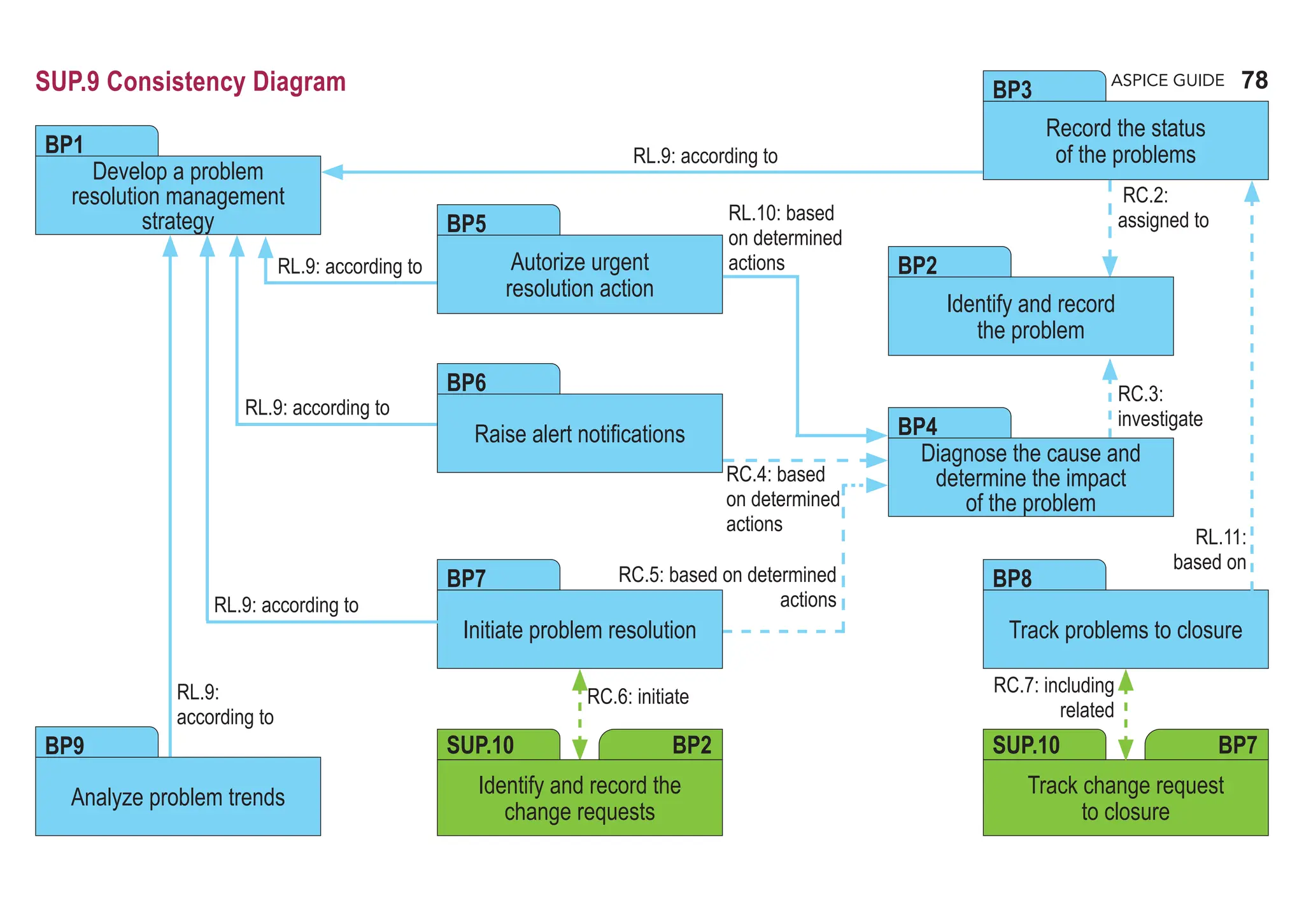
SUP.9 Problem Resolution Management
The purpose of the Problem Resolution Management Process is to ensure that problems are identified, analyzed, managed and
controlled to resolution.
Process outcomes – as a result of successful implementation of this process
1. a problem resolution management strategy is developed;
2. problems are recorded, uniquely identified and classified;
3. problems are analyzed and assessed to identify an appropriate solution;
4. problem resolution is initiated;
5. problems are tracked to closure; and
6. the status of problems and their trend are known.
Output work products](https://image.slidesharecdn.com/aspice-guide-km2021-04-240204182441-58722c47/75/ASPICE-Guide-KM2021-04-pdf-74-2048.jpg)
![75
ASPICE GUIDE
Develop a problem resolution management strategy. Develop a problem resolution management strategy, including
problem resolution activities, a status model for the problems, alert notifications, responsibilities for performing these activities
and an urgent resolution strategy. Interfaces to affected parties are defined and definitions are maintained. [OUTCOME 1]
Problem resolution activities can be different during the product life cycle, e.g. during prototype construction and series
development.
Identify and record the problem. Each problem is uniquely identified, described and recorded. Supporting information
should be provided to reproduce and diagnose the problem. [OUTCOME 2]
Supporting information typically includes the origin of the problem, how it can be reproduced, environmental information,
by whom it has been detected, etc.
Unique identification supports traceability to changes made.
Record the status of problems. A status according to the status model is assigned to each problem to facilitate tracking.
[OUTCOME 6]
BP 3
BP 2
SUP.9 with 9 Base practices
BP 1
1
75
SUP.9
51ff: SAP.RL.1-4
182: SUP.9.RL.1-2
184: SUP.9.RL.7-8, SUP.9.RC.1
2
3
184: SUP.9.RL.7-8, SUP.9.RC.1
186: SUP.9.RL.9, SUP.9.RC.2
<no rule; no recommendation>](https://image.slidesharecdn.com/aspice-guide-km2021-04-240204182441-58722c47/75/ASPICE-Guide-KM2021-04-pdf-75-2048.jpg)
![76
ASPICE GUIDE
SUP.9 with 9 Base practices
BP 4
4
76
BP 5
BP 6
Diagnose the cause and determine the impact of the problem. Investigate the problem and determine its cause and
impact in order to categorize the problem and to determine appropriate actions. [OUTCOME 2, 3]
Problem categorization (e.g. A, B, C, light, medium, severe) may be based on severity, impact, criticality, urgency,
relevance for the change process, etc.
Authorize urgent resolution action. If according to the strategy a problem requires an urgent resolution, authorization
shall be obtained for immediate action also according to the strategy. [OUTCOME 4]
Raise alert notifications. If according to the strategy the problem has a high impact on other systems or other affected
parties, an alert notification needs to be raised also according to the strategy. [OUTCOME 4]
183: SUP.9.RL.3-6
186: SUP.9.RC.3
186: SUP.9.RL.9-10
183: SUP.9.RL.3-6
186: SUP.9.RL.9, SUP.9.RC.4](https://image.slidesharecdn.com/aspice-guide-km2021-04-240204182441-58722c47/75/ASPICE-Guide-KM2021-04-pdf-76-2048.jpg)
![77
ASPICE GUIDE
BP 8
BP 9
7
SUP.9 with 9 Base practices 77
SUP.9
Initiate problem resolution. Initiate appropriate actions according to the strategy to resolve the problem including review
of those actions, or initiate a change request. [OUTCOME 4]
Appropriate actions may include the initiating of a change request. See SUP.10 for managing of change requests.
The implementation of process improvements (to prevent problems) is done in the process improvement process (PIM.3).
The implementation of generic project management improvements (e.g. lessons learned) are part of the project
management process (MAN.3). The implementation of generic work product related improvements are part of the
quality assurance process (SUP.1).
Track problems to closure. Track the status of problems to closure including all related change requests. A formal
acceptance has to be authorized before closing the problem. [OUTCOME 5, 6]
Analyze problem trends. Collect and analyze problem resolution management data, identify trends, and initiate project
related actions, according to the strategy. [OUTCOME 6]
Collected data typically contains information about where the problems occurred, how and when they were found,
what were their impacts, etc.
BP 7
6
5
186: SUP.9.RL.9, SUP.9.RC.5
195: SUP.10.RC.16
184: SUP.9.RL.7-8, SUP.9.RC.1
186: SUP.9.RL.11
186: SUP.9.RL.9](https://image.slidesharecdn.com/aspice-guide-km2021-04-240204182441-58722c47/75/ASPICE-Guide-KM2021-04-pdf-77-2048.jpg)

![80
ASPICE GUIDE
08-28 Change management plan [OUTCOME 1] 13-19 Review record [OUTCOME 7]
13-16 Change request [OUTCOME 2, 3, 4, 5, 6, 7] 13-21 Change control record [OUTCOME 8,9]
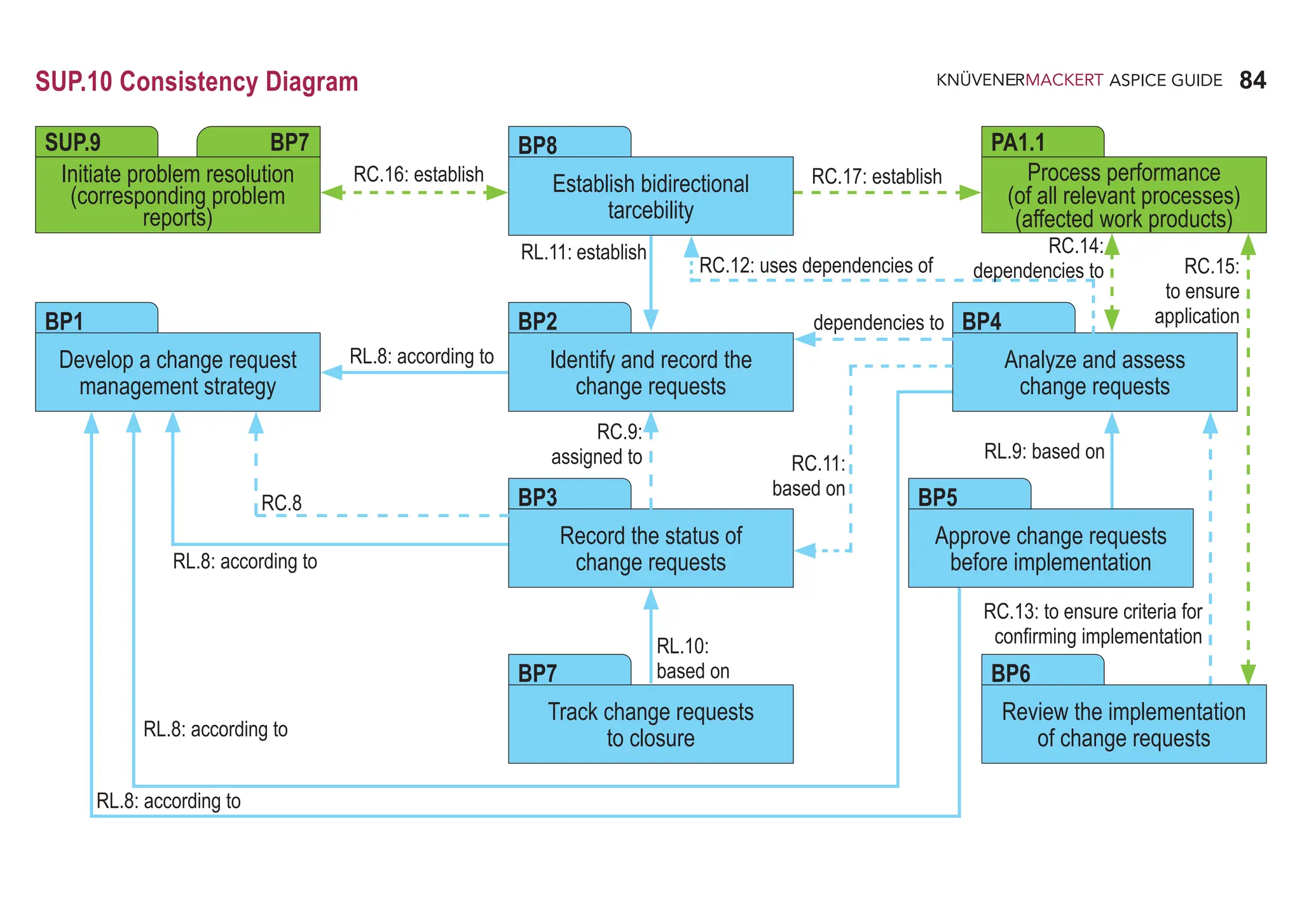
SUP.10 Change Request Management
The purpose of the Change Request Management Process is to ensure that change requests are managed, tracked and implemented.
Process outcomes – as a result of successful implementation of this process
1. a change request management strategy is developed;
2. requests for changes are recorded and identified;
3. dependencies and relationships to other change requests are identified;
4. criteria for confirming implementation of change requests are defined;
5. requests for change are analyzed, and resource requirements are estimated;
6. changes are approved and prioritized on the basis of analysis results and availability of resources;
7. approved changes are implemented and tracked to closure;
8. the status of all change requests is known; and
9. bidirectional traceability is established between change requests and affected work products..
Output work products](https://image.slidesharecdn.com/aspice-guide-km2021-04-240204182441-58722c47/75/ASPICE-Guide-KM2021-04-pdf-80-2048.jpg)
![81
ASPICE GUIDE
SUP.10 with 8 Base practices
BP 1
2
4
3
1
81
SUP.10
BP 2
Develop a change request management strategy. Develop a change request management strategy, including change
request activities, a status model for the change requests, analysis criteria, and responsibilities for performing these activities.
Interfaces to affected parties are defined and maintained. [OUTCOME 1]
A status model for change requests may contain: open, under investigation, approved for implementation, allocated,
implemented, fixed, closed, etc.
Typical analysis criteria are: resource requirements, scheduling issues, risks, benefits, etc.
Change request activities ensure that change requests are systematically identified, described, recorded, analyzed,
implemented, and managed.
The change request management strategy may cover different proceedings across the product life cycle, e.g. during
prototype construction and series development.
Identify and record the change requests. Each change request is uniquely identified, described, and recorded according
to the strategy, including the initiator and reason of the change request. [OUTCOME 2, 3]
51ff: SAP.RL.1-4
79: APA.RL.6
189: SUP.10.RL.1
187: SUP.9.RC.6
194: SUP.10.RL.8
233: CL2.RC.16](https://image.slidesharecdn.com/aspice-guide-km2021-04-240204182441-58722c47/75/ASPICE-Guide-KM2021-04-pdf-81-2048.jpg)
![82
ASPICE GUIDE
SUP.10 with 8 Base practices 82
BP 4
BP 5
6
5
BP 3
Record the status of change requests. A status according to the status model is assigned to each change request to
facilitate tracking. [OUTCOME 8]
Analyze and assess change requests. Change requests are analyzed according to the strategy including their
dependencies to affected work products and other change requests. Assess the impact of the change requests and establish
criteria for confirming implementation. [OUTCOME 3, 4, 5, 9]
Approve change requests before implementation. Change requests are prioritized based on analysis results and
availability of resources before implementation and approved according to the strategy. [OUTCOME 6]
A Change Control Board (CCB) is a common mechanism used to approve change requests.
Prioritization of change requests may be done by allocation to releases.
192ff: SUP.10.RL.6-7-8, SUP.10.RC.7-10
233: CL2.RC.16
73: PLS.RC.6
79: APA.RL.5
191: SUP.10.RL.4-5, SUP.10.RC.5-6
194: SUP.10.RL.8, SUP.10.RC.11-12
190: SUP.10.RL.3, SUP.10.RC.4
194: SUP.10.RL.8-9](https://image.slidesharecdn.com/aspice-guide-km2021-04-240204182441-58722c47/75/ASPICE-Guide-KM2021-04-pdf-82-2048.jpg)
![83
ASPICE GUIDE
BP 6
83
SUP.10
SUP.10 with 8 Base practices 83
191: SUP.10.RL.4-5, SUP.10.RC.5-6
194: SUP.10.RC.13
BP 8
BP 7
7
187: SUP.9.RC.7
192: SUP.10.RL.6-7, SUP.10.RC.7
195: SUP.10.RL.10
233: CL2.RC.16
Review the implementation of change requests. The implementation of change requests is reviewed before closure to
ensure that their criteria for confirming implementation are satisfied, and that all relevant processes have been applied.
[OUTCOME 7, 8]
Track change requests to closure. Change requests are tracked until closure. Feedback to the initiator is provided.
[OUTCOME 7, 8]
Establish bidirectional traceability. Establish bidirectional traceability between change requests and work products affected
by the change requests. In case that the change request is initiated by a problem, establish bidirectional traceability between
change requests and the corresponding problem reports. [OUTCOME 9]
Bidirectional traceability supports consistency, completeness and impact analysis.
36ff: TAC.RC.1-3
195: SUP.10.RL.11](https://image.slidesharecdn.com/aspice-guide-km2021-04-240204182441-58722c47/75/ASPICE-Guide-KM2021-04-pdf-83-2048.jpg)

![86
ASPICE GUIDE
SPL.2 Product Release
The purpose of the Product Release Process is to control the release of a product to the intended customer.
Process outcomes – as a result of successful implementation of this process
1. the contents of the product release are determined;
2. the release is assembled from configured items;
3. the release documentation is defined and produced;
4. the release delivery mechanism and media are determined;
5. release approval is effected against defined criteria;
6. the product release is made available to the intended customer; and
7. confirmation of release is obtained.
Output work products
08-16 Release plan [OUTCOME 1, 3] 13-06 Delivery record [OUTCOME 6,7]
11-03 Product release information [OUTCOME 1, 3, 4, 6] 13-13 Product release approval record [OUTCOME 5]
11-04 Product release package [OUTCOME 2, 3, 6] 15-03 Configuration status report [OUTCOME 2]
11-07 Temporary solution [OUTCOME 6] 18-06 Product release criteria [OUTCOME 5, 7]](https://image.slidesharecdn.com/aspice-guide-km2021-04-240204182441-58722c47/75/ASPICE-Guide-KM2021-04-pdf-86-2048.jpg)
![87
ASPICE GUIDE
BP 4
BP 2
SPL.2 with 13 Base practices
Define the functional content of releases. Establish a plan for releases that identifies the functionality to be included in each
release. [OUTCOME 1, 3]
The plan should point out which application parameters influencing the identified functionality are effective for which
release.
Define release products. The products associated with the release are defined. [OUTCOME 1]
The release products may include programming tools where these are stated. In automotive terms a release may be
associated with a sample e.g. A, B, C.
Establish a product release classification and numbering scheme. A product release classification and numbering scheme
are established based upon the intended purpose and expectations of the release(s). [OUTCOME 2]
A release numbering implementation may include
• the major release number
• the feature release number
• the defect repair number
• the alpha or beta release
• the iteration within the alpha or beta release
Define the build activities and build environment. A consistent build process is established and maintained. [OUTCOME 2]
A specified and consistent build environment should be used by all parties.
Build the release from configured items. The release is built from configured items to ensure integrity. [OUTCOME 2]
Where relevant the software release should be programmed onto the correct hardware revision before release.
BP 1
1
2
4
BP 3
BP 5
3
5
87
SPL.2](https://image.slidesharecdn.com/aspice-guide-km2021-04-240204182441-58722c47/75/ASPICE-Guide-KM2021-04-pdf-87-2048.jpg)
![88
ASPICE GUIDE
SPL.2 with 13 Base practices
BP 7
Communicate the type, service level and duration of support for a release. The type, service level and duration of
support for a release are identified and communicated. [OUTCOME 3]
Determine the delivery media type for the release. The media type for product delivery is determined in accordance with
the needs of the customer. [OUTCOME 4]
The media type for delivery may be intermediate (placed on an adequate media and delivered to customer), or direct
(such as delivered in firmware as part of the package) or a mix of both. The release may be delivered electronically by
placement on a server. The release may also need to be duplicated before delivery.
Identify the packaging for the release media. The packaging for different types of media is identified. [OUTCOME 4]
The packaging for certain types of media may need physical or electronic protection for instance specific encryption
techniques.
Define and produce the product release documentation/release notes. Ensure that all documentation to support the
release is produced, reviewed, approved and available. [OUTCOME 3]
Ensure product release approval before delivery. Criteria for the product release are satisfied before release takes place.
[OUTCOME 5]
Ensure consistency. Ensure consistency between software release number, paper label and EPROM-Label (if relevant).
[OUTCOME 5]
BP 6
6
BP 8
7
BP 9
BP 10
BP 11
88](https://image.slidesharecdn.com/aspice-guide-km2021-04-240204182441-58722c47/75/ASPICE-Guide-KM2021-04-pdf-88-2048.jpg)
![89
ASPICE GUIDE
SPL.2 with 13 Base practices
BP 13
Provide a release note. A release is supported by information detailing key characteristics of the release. [OUTCOME 6]
The release note may include an introduction, the environmental requirements, installation procedures, product
invocation, new feature identification and a list of defect resolutions, known defects and workarounds.
Deliver the release to the intended customer. The product is delivered to the intended customer with positive confirmation
of receipt. [OUTCOME 6, 7]
Confirmation of receipt may be achieved by hand, electronically, by post, by telephone or through a distribution service
provider.
These practices are typically supported by the SUP.8 Configuration Management Process.
BP 12
8
9
10
89
SPL.2](https://image.slidesharecdn.com/aspice-guide-km2021-04-240204182441-58722c47/75/ASPICE-Guide-KM2021-04-pdf-89-2048.jpg)
![90
ASPICE GUIDE
08-19 Risk management plan [OUTCOME 6] 13-21 Change control record [OUTCOME 3, 4]
08-20 Risk mitigation plan [OUTCOME 6] 15-01 Analysis report [OUTCOME 2, 3, 6]
13-04 Communication record [OUTCOME 1, 4] 17-03 Stakeholder Requirements [OUTCOME 1, 2]
13-19 Review record [OUTCOME 4, 5]
SYS.1 Requirements Elicitation
The purpose of the Requirements Elicitation Process is to gather, process, and track evolving stakeholder needs and requirements
throughout the lifecycle of the product and/or service so as to establish a requirements baseline that serves as the basis for defining
the needed work products.
Process outcomes – as a result of successful implementation of this process
1. continuing communication with the stakeholder is established;
2. agreed stakeholder requirements are defined and baselined;
3. a change mechanism is established to evaluate and incorporate changes to stakeholder requirements into the baselined
requirements based on changing stakeholder needs;
4. a mechanism is established for continuous monitoring of stakeholder needs;
5. a mechanism is established for ensuring that customers can easily determine the status and disposition of their requests; and
6. changes arising from changing technology and stakeholder needs are identified, the associated risks assessed and their impact
managed.
Output work products](https://image.slidesharecdn.com/aspice-guide-km2021-04-240204182441-58722c47/75/ASPICE-Guide-KM2021-04-pdf-90-2048.jpg)
![91
ASPICE GUIDE
BP 3
SYS.1 with 6 Base practices
Obtain stakeholder requirements and requests. Obtain and define stakeholder requirements and requests through direct
solicitation of customer input and through review of customer business proposals (where relevant), target operating and
hardware environment, and other documents bearing on customer requirements. [OUTCOME 1, 4]
Requirements elicitation may involve the customer and the supplier.
The agreed stakeholder requirements and evaluation of any change may be based on feasibility studies and/or cost and
time analyzes.
The information needed to keep traceability for each customer requirement has to be gathered and documented.
Understand stakeholder expectations. Ensure that both supplier and customer understand each requirement in the same
way. [OUTCOME 2]
Reviewing the requirements and requests with the customer supports a better understanding of customer needs and
expectations. Refer to the process SUP.4 Joint Review.
Agree on requirements. Obtain an explicit agreement from all relevant parties to work on these requirements. [OUTCOME 2]
Establish stakeholder requirements baseline. Formalize the stakeholder‘s requirements and establish them as a baseline
for project use and monitoring against stakeholder needs. The supplier should determine the requirements not stated by the
stakeholder but necessary for specified and intended use and include them in the baseline. [OUTCOME 2,3]
BP 1
1
2
4
BP 2
BP 4
3
91
SYS.1](https://image.slidesharecdn.com/aspice-guide-km2021-04-240204182441-58722c47/75/ASPICE-Guide-KM2021-04-pdf-91-2048.jpg)
![92
ASPICE GUIDE
SYS.1 with 6 Base practices
Manage stakeholder requirements changes. Manage all changes made to the stakeholder requirements against the
stakeholder requirements baseline to ensure enhancements resulting from changing technology and stakeholder needs
are identified and that those who are affected by the changes are able to assess the impact and risks and initiate appropriate
change control and mitigation actions. [OUTCOME 3, 6]
Requirements change may arise from different sources as for instance changing technology and stakeholder needs,
legal constraints.
An information management system may be needed to manage, store and reference any information gained and
needed in defining agreed stakeholder requirements.
Establish customer-supplier query communication mechanism. Provide means by which the customer can be aware
of the status and disposition of their requirements changes and the supplier can have the ability to communicate necessary
information, including data, in a customer-specified language and format. [OUTCOME 5]
Any changes should be communicated to the customer before implementation in order that the impact, in terms of time,
cost and functionality can be evaluated.
This may include joint meetings with the customer or formal communication to review the status for their requirements
and requests; Refer to the process SUP.4 Joint Review.
The formats of the information communicated by the supplier may include computer-aided design data and electronic
data exchange.
BP5
5
6
BP6
7
8
9
92](https://image.slidesharecdn.com/aspice-guide-km2021-04-240204182441-58722c47/75/ASPICE-Guide-KM2021-04-pdf-92-2048.jpg)

![94
ASPICE GUIDE
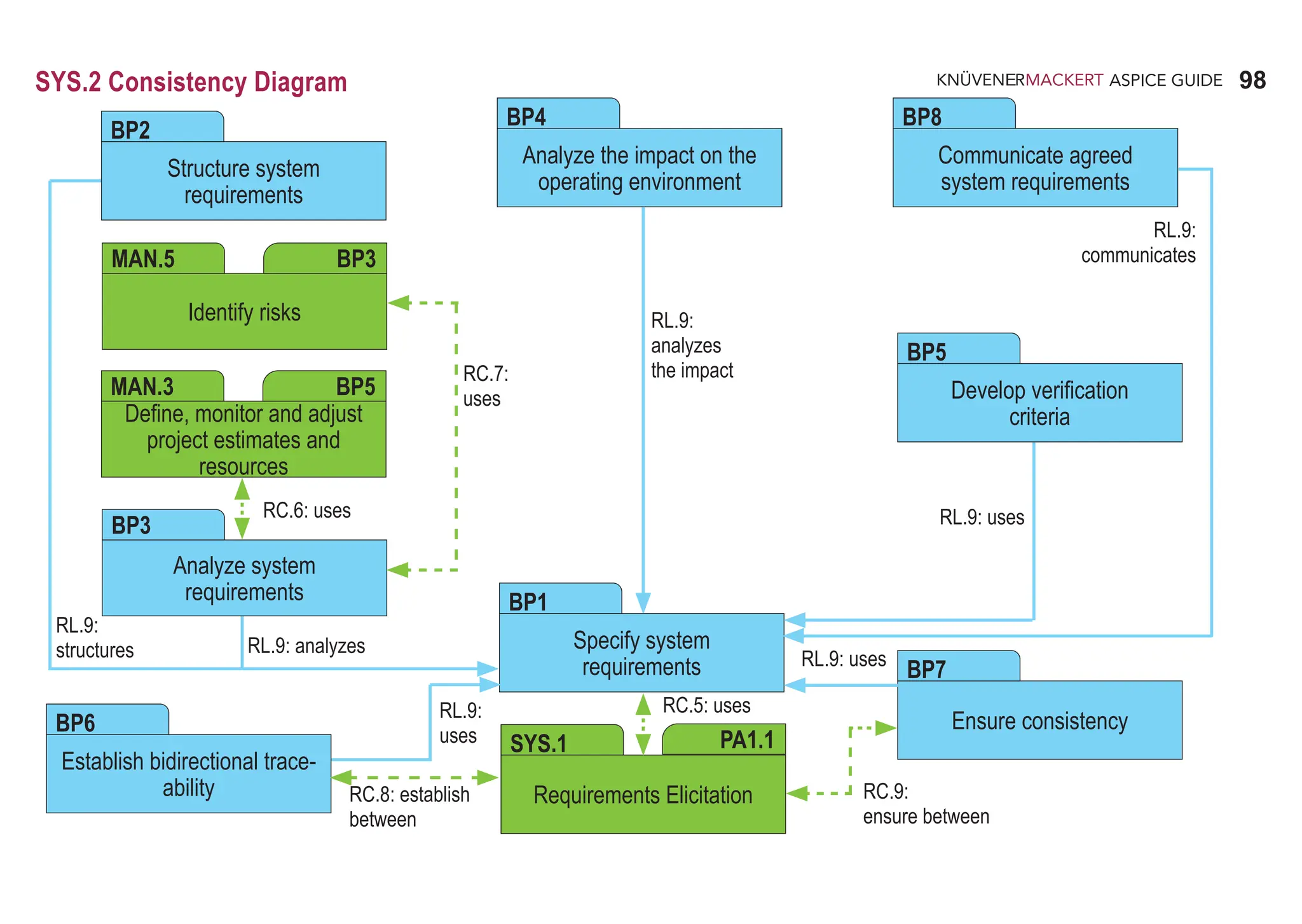
SYS.2 System Requirements Analysis
The purpose of the System Requirements Analysis Process is to transform the defined stakeholder requirements into a set of system
requirements that will guide the design of the system.
Process outcomes – As a result of successful implementation of this process:
1. a defined set of system requirements is established;
2. system requirements are categorized and analyzed for correctness and verifiability;
3. the impact of system requirements on the operating environment is analyzed;
4. prioritization for implementing the system requirements is defined;
5. the system requirements are updated as needed;
6. consistency and bidirectional traceability are established between stakeholder requirements and system requirements;
7. the system requirements are evaluated for cost, schedule and technical impact; and
8. the system requirements are agreed and communicated to all affected parties.
Output work products
13-04 Communication record [OUTCOME 8] 15-01 Analysis report [OUTCOME 2, 3, 4, 7]
13-19 Review record [OUTCOME 6] 17-08 Interface requirements specification [OUTCOME 1, 3]
13-21 Change control record [OUTCOME 1] 17-12 System requirements specification [OUTCOME 1, 5]
13-22 Traceability record [OUTCOME 6] 17-50 Verification criteria [OUTCOME 2]](https://image.slidesharecdn.com/aspice-guide-km2021-04-240204182441-58722c47/75/ASPICE-Guide-KM2021-04-pdf-94-2048.jpg)
![95
ASPICE GUIDE
SYS.2 with 8 Base practices
BP 1
1
2
95
SYS.2
Specify system requirements. Use the stakeholder requirements and changes to the stakeholder requirements to identify
the required functions and capabilities of the system. Specify functional and non-functional system requirements in a system
requirements specification. [OUTCOME 1, 5, 7]
Application parameter influencing functions and capabilities are part of the system requirements.
For changes to the stakeholder‘s requirements SUP.10 applies.
Structure system requirements. Structure the system requirements in the system requirements specification by e.g.
• grouping to project relevant clusters,
• sorting in a logical order for the project,
• categorizing based on relevant criteria for the project,
• prioritizing according to stakeholder needs.
[OUTCOME 2, 4]
Prioritizing typically includes the assignment of functional content to planned releases. Refer to SPL.2.BP1
BP 2
3
76f: APA.RL.1, 3
88: SYS.2.RL.1-3
94: SYS.2.RC.5
88f: SYS.2.RL.4-5, SYS.2.RC.1
94: SYS.2.RL.9](https://image.slidesharecdn.com/aspice-guide-km2021-04-240204182441-58722c47/75/ASPICE-Guide-KM2021-04-pdf-95-2048.jpg)
![96
ASPICE GUIDE
BP 3
BP 4
SYS.2 with 8 Base practices 96
BP5
Analyze system requirements. Analyze the specified system requirements including their interdependencies to ensure
correctness, technical feasibility and verifiability, and to support risk identification. Analyze the impact on cost, schedule and
the technical impact. [OUTCOME 1, 2, 7]
The analysis of impact on cost and schedule supports the adjustment of project estimates. Refer to MAN.3.BP5.
Analyze the impact on the operating environment. Identify the interfaces between the specified system and other elements
of the operating environment. Analyze the impact that the system requirements will have on these interfaces and the operating
environment. [OUTCOME 3, 7]
Develop verification criteria. Develop the verification criteria for each system requirement that define the qualitative and
quantitative measures for the verification of a requirement. [OUTCOME 2, 7]
Verification criteria demonstrate that a requirement can be verified within agreed constraints and is typically used as the
input for the development of the system test cases or other verification measures that ensures compliance with the system
requirements.
Verification which cannot be covered by testing is covered by SUP.2.
5
6
4
60: AGE.RC.3
89: SYS.2.RL.6, SYS.2.RC.2
94: SYS.2.RL.9
90: SYS.2.RC.3-4
94: SYS.2.RL.9
48: VEC.RL.1-2
91: SYS.2.RL.7
94: SYS.2.RL.9](https://image.slidesharecdn.com/aspice-guide-km2021-04-240204182441-58722c47/75/ASPICE-Guide-KM2021-04-pdf-96-2048.jpg)
![97
ASPICE GUIDE
SYS.2
SYS.2 with 8 Base practices 97
BP6
BP8
Establish bidirectional traceability. Establish bidirectional traceability between stakeholder requirements and system
requirements. [OUTCOME 6]
Bidirectional traceability supports coverage, consistency and impact analysis.
Ensure consistency. Ensure consistency between stakeholder requirements and system requirements. [OUTCOME 6]
Consistency is supported by bidirectional traceability and can be demonstrated by review records.
Communicate agreed system requirements. Communicate the agreed system requirements and updates to system
requirements to all relevant parties. [OUTCOME 8]
BP7
8
7
36ff: TAC.RC.1-4
41: TAC.RL.2-3
94: SYS.2.RL.9, SYS.2.RC.8
39ff: TAC.RL.1-3, TAC.RC.4
92ff: SYS.2.RL.8-9, SYS.2.RC.9
233: CL2.RC.18
44: SAC.RL.1
46: SAC.RC.4-6
94: SYS.2.RL.9
225: CL2.RC.9](https://image.slidesharecdn.com/aspice-guide-km2021-04-240204182441-58722c47/75/ASPICE-Guide-KM2021-04-pdf-97-2048.jpg)

![100
ASPICE GUIDE
SYS.3 System Architectural Design
The purpose of the System Architectural Design Process is to establish a system architectural design and identify which system
requirements are to be allocated to which elements of the system, and to evaluate the system architectural design against defined
criteria.
Process outcomes – As a result of successful implementation of this process:
1. a system architectural design is defined that identifies the elements of the system;
2. the system requirements are allocated to the elements of the system;
3. the interfaces of each system element are defined;
4. the dynamic behavior of the system elements is defined;
5. consistency and bidirectional traceability are established between system requirements and system architectural design; and
6. the system architectural design is agreed and communicated to all affected parties.
Output work products
04-06 System architectural design [OUTCOME 1, 2, 3, 4, 5] 13-22 Traceability record [OUTCOME 5]
13-04 Communication record [OUTCOME 6] 17-08 Interface requirements specification [OUTCOME 3]
13-19 Review record [OUTCOME 5]](https://image.slidesharecdn.com/aspice-guide-km2021-04-240204182441-58722c47/75/ASPICE-Guide-KM2021-04-pdf-100-2048.jpg)
![101
ASPICE GUIDE
SYS.3
BP 3
SYS.3 with 8 Base practices
BP 1
BP 2
1
101
Develop system architectural design. Develop and document the system architectural design that specifies the elements
of the system with respect to functional and non-functional system requirements. [OUTCOME 1]
The development of system architectural design typically includes the decomposition into elements across appropriate
hierarchical levels.
Allocate system requirements. Allocate the system requirements to the elements of the system architectural design.
[OUTCOME 2]
Define interfaces of system elements. Identify, develop and document the interfaces of each system element.
[OUTCOME 3]
Describe dynamic behavior. Evaluate and document the dynamic behavior of the interaction between system elements.
[OUTCOME 4]
Dynamic behavior is determined by operating modes (e.g. start-up, shutdown, normal mode, calibration, diagnosis, etc.).
BP 4
2
97: SYS.3.RL.1-2
103: SYS.3.RC.2
98: SYS.3.RL.3
103: SYS.3.RL.7
99: SYS.3.RL.4
103: SYS.3.RL.7
99: SYS.3.RL.5
103: SYS.3.RL.7](https://image.slidesharecdn.com/aspice-guide-km2021-04-240204182441-58722c47/75/ASPICE-Guide-KM2021-04-pdf-101-2048.jpg)
![102
ASPICE GUIDE
Evaluate alternative system architectures. Define evaluation criteria for the architecture. Evaluate alternative system
architectures according to the defined criteria. Record the rationale for the chosen system architecture. [OUTCOME 1]
Evaluation criteria may include quality characteristics (modularity, maintainability, expandability, scalability, reliability,
security realization and usability) and results of make-buy-reuse analysis.
Establish bidirectional traceability. Establish bidirectional traceability between system requirements and elements
of the system architectural design. [OUTCOME 5]
Bidirectional traceability covers allocation of system requirements to the elements of the system architectural
design.
Bidirectional traceability supports coverage, consistency and impact analysis.
SYS.3 with 8 Base practices
BP6
4
5
102
BP 5
3
101ff: SYS.3.RL.6-7, SYS.3.RC.1
36ff: TAC.RC.1-4
41: TAC.RL.2-3
103: SYS.3.RL.7-8, SYS.3.RC.3](https://image.slidesharecdn.com/aspice-guide-km2021-04-240204182441-58722c47/75/ASPICE-Guide-KM2021-04-pdf-102-2048.jpg)
![103
ASPICE GUIDE
SYS.3
7
6
BP7
BP8
Ensure consistency. Ensure consistency between system requirements and the system architectural design.
[OUTCOME 1, 2, 5, 6]
Consistency is supported by bidirectional traceability and can be demonstrated by review records.
System requirements typically include system architectural requirements. Refer to BP5.
Communicate agreed system architectural design. Communicate the agreed system architectural design and updates to
system architectural design to all relevant parties. [OUTCOME 6]
SYS.3 with 8 Base practices
39: TAC.RL.1
40: TAC.RC.4
41: TAC.RL.2-3
103: SYS.3.RL.7, SYS.3.RC.4
233: CL2.RC.18
44: SAC.RL.1
46: SAC.RC.4-6
103: SYS.3.RL.7
225: CL2.RC.9
103](https://image.slidesharecdn.com/aspice-guide-km2021-04-240204182441-58722c47/75/ASPICE-Guide-KM2021-04-pdf-103-2048.jpg)
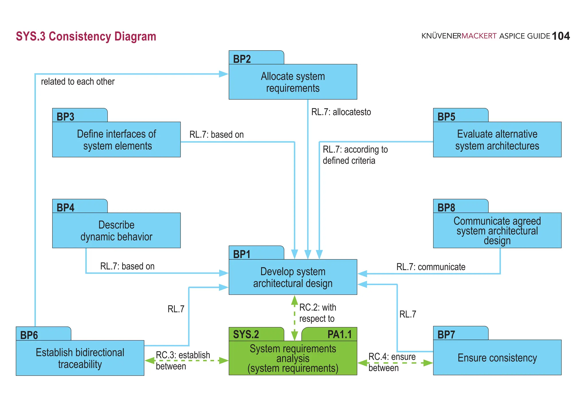

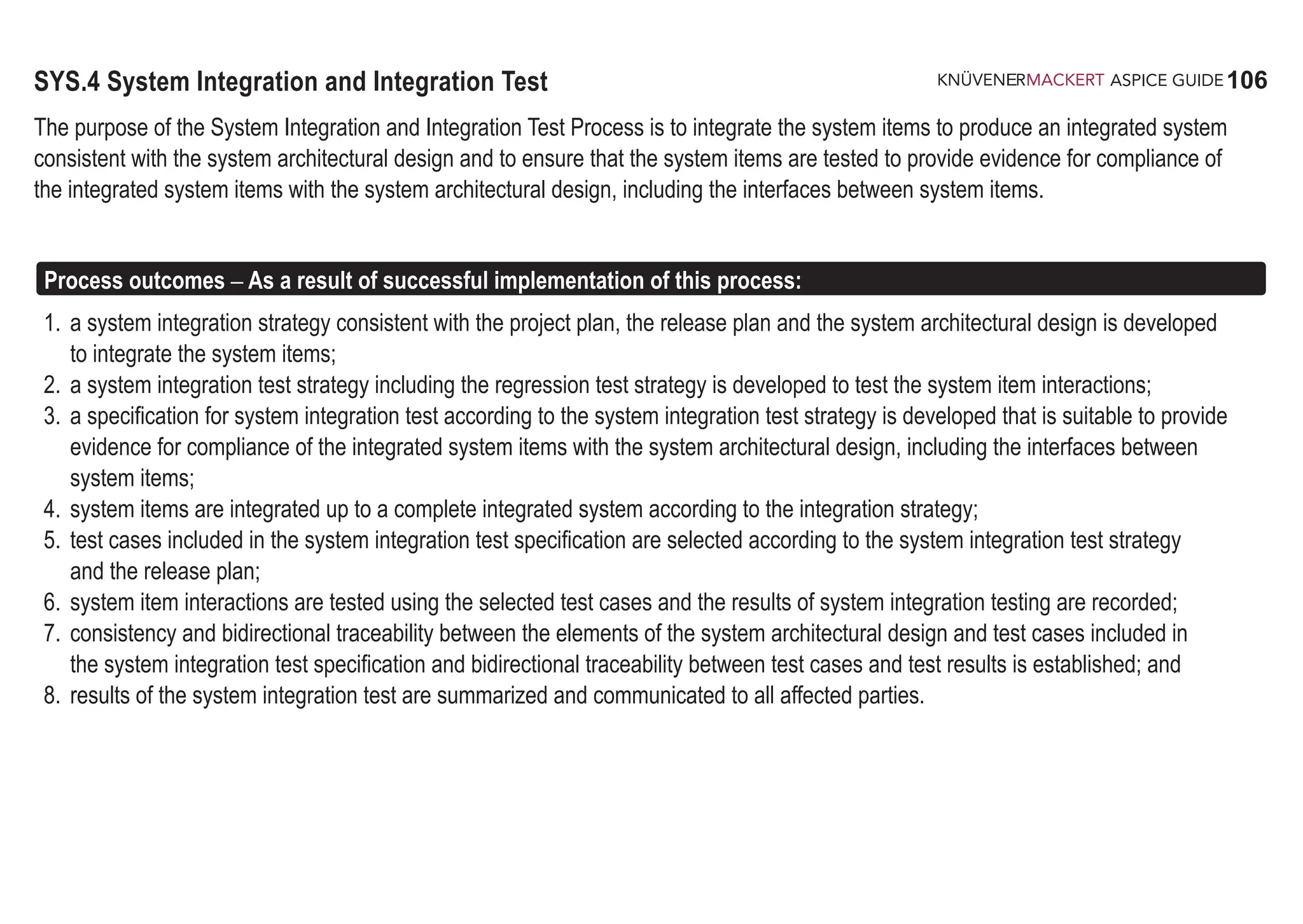
![107
ASPICE GUIDE
BP 2
Output work products
SYS.4 with 9 Base practices
Develop system integration strategy. Develop a strategy for integrating the system items consistent with the project plan
and the release plan. Identify system items based on the system architectural design and define a sequence for integrating
them. [OUTCOME 1]
Develop system integration test strategy including regression test strategy. Develop a strategy for testing the integrated
system items following the integration strategy. This includes a regression test strategy for re-testing integrated system items
if a system item is changed. [OUTCOME 2]
08-50 Test specification [OUTCOME 3, 5] 13-19 Review record [OUTCOME 7]
08-52 Test plan [OUTCOME 1, 2] 13-22 Traceability record [OUTCOME 7]
11-06 System [OUTCOME 4] 13-50 Test result [OUTCOME 6, 8]
13-04 Communication record [OUTCOME 8]
107
SYS.4
51ff: SAP.RL.1-4
65: DID.RL.10
104: SYS.4.RL.1
111: SYS.4.RC.2-3
BP 1
51ff: SAP.RL.1-4
81: APA.RL.8
106: SYS.4.RL.2-3](https://image.slidesharecdn.com/aspice-guide-km2021-04-240204182441-58722c47/75/ASPICE-Guide-KM2021-04-pdf-107-2048.jpg)
![108
ASPICE GUIDE
Base practices 3-4
SYS.4 with 9 Base practices 108
Develop specification for system integration test. Develop the test specification for system integration test including the
test cases for each integration step of a system item according to the system integration test strategy. The test specification
shall be suitable to provide evidence for compliance of the integrated system items with the system architectural design.
[OUTCOME 3]
The interface descriptions between system elements are an input for the system integration test cases.
Compliance to the architectural design means that the specified integration tests are suitable to prove that the
interfaces between the system items fulfill the specification given by the system architectural design.
The system integration test cases may focus on
• the correct signal flow between system items
• the timelines and timing dependencies of signal flow between system items
• the correct interpretation of signals by all system items using an interface
• the dynamic interaction between system items
The system integration test may be supported using simulation of the environment
(e.g. Hardware-in-the-Loop simulation, vehicle network simulations, digital mock-up).
BP3
1
2
3
4
106: SYS.4.RL.4
110: SYS.4.RL.9, 11
111: SYS.4.RC.4](https://image.slidesharecdn.com/aspice-guide-km2021-04-240204182441-58722c47/75/ASPICE-Guide-KM2021-04-pdf-108-2048.jpg)
![109
ASPICE GUIDE
BP 4
Base practices 3-4
SYS.4 with 9 Base practices 109
5
SYS.4
110: SYS.4.RL.12
BP5
107: SYS.4.RL.5, SYS.4.RC.1
110: SYS.4.RL.9, 13-14
111: SYS.4.RC.5
6
BP6
Integrate system items. Integrate the system items to an integrated system according to the system integration strategy.
[OUTCOME 4]
The system integration can be performed step wise integrating system items (e.g. the hardware elements as prototype
hardware, peripherals (sensors and actuators), the mechanics and integrated software) to produce a system consistent
with the system architectural design.
Select test cases. Select test cases from the system integration test specification. The selection of test cases shall have
sufficient coverage according to the system integration test strategy and the release plan. [OUTCOME 5]
Perform system integration test. Perform the system integration test using the selected test cases. Record the integration
test results and logs. [OUTCOME 6]
See SUP.9 for handling of non-conformances.
107f: SYS.4.RL.6-8
110: SYS.4.RL.15](https://image.slidesharecdn.com/aspice-guide-km2021-04-240204182441-58722c47/75/ASPICE-Guide-KM2021-04-pdf-109-2048.jpg)
![110
ASPICE GUIDE
Base practices 3-4
SYS.4 with 9 Base practices
BP8
8
110
BP9
9
Summarize and communicate results. Summarize the system integration test results and communicate them to all
affected parties. [OUTCOME 8]
Providing all necessary information from the test case execution in a summary enables other parties to judge the
consequences
BP7
7
Establish bidirectional traceability. Establish bidirectional traceability between elements of the system architectural
design and test cases included in the system integration test specification.
Establish bidirectional traceability between test cases included in the system integration test specification and system
integration test results. [OUTCOME 7]
Bidirectional traceability supports coverage, consistency and impact analysis.
Ensure consistency. Ensure consistency between elements of the system architectural design and test cases included in
the system integration test specification. [OUTCOME 7]
Consistency is supported by bidirectional traceability and can be demonstrated by review records.
36ff: TAC.RC.1-4
111: SYS.4.RC.6
39: TAC.RL.1
40: TAC.RC.4
111: SYS.4.RC.7
233: CL2.RC.18
43ff: SAC.RC.1-6
225: CL2.RC.10](https://image.slidesharecdn.com/aspice-guide-km2021-04-240204182441-58722c47/75/ASPICE-Guide-KM2021-04-pdf-110-2048.jpg)
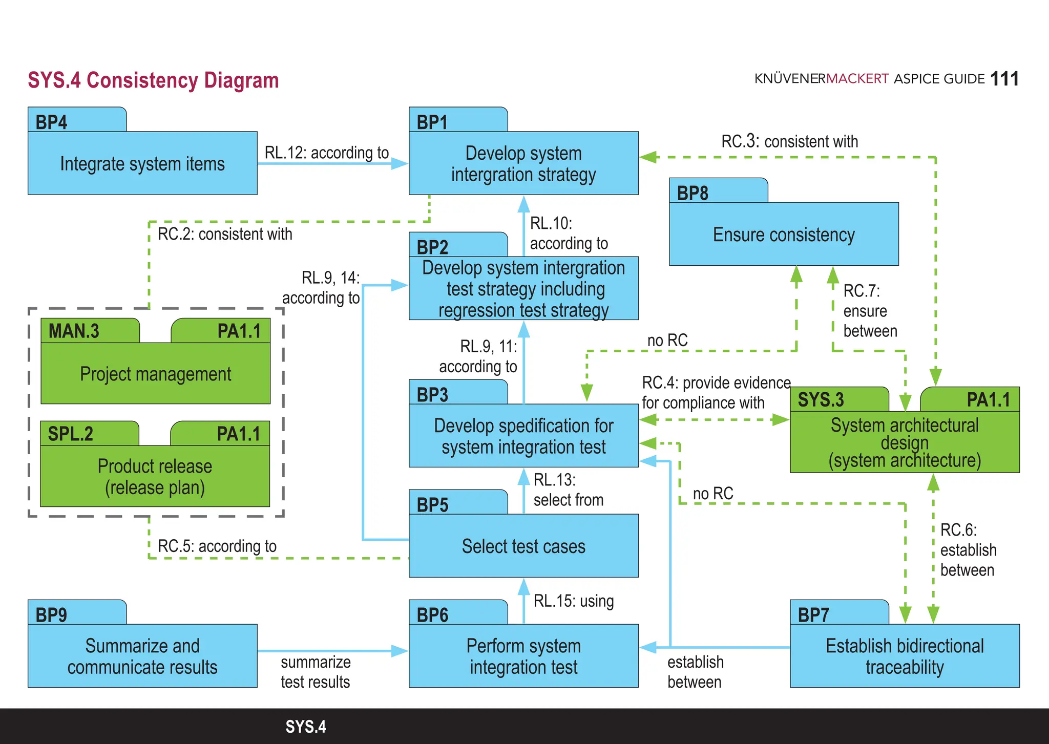
![112
ASPICE GUIDE
SYS.5 System Qualification Test
The purpose of the System Qualification Test Process is to ensure that the integrated system is tested to provide evidence for
compliance with the system requirements and that the system is ready for delivery.
Process outcomes – As a result of successful implementation of this process:
1. a system qualification test strategy including regression test strategy consistent with the project plan and release plan is developed
to test the integrated system;
2. a specification for system qualification test of the integrated system according to the system qualification test strategy is developed
that is suitable to provide evidence for compliance with the system requirements;
3. test cases included in the system qualification test specification are selected according to the system qualification test strategy and
the release plan;
4. the integrated system is tested using the selected test cases and the results of system qualification test are recorded;
5. consistency and bidirectional traceability are established between system requirements and test cases included in the system
qualification test specification and between test cases and test results; and
6. results of the system qualification test are summarized and communicated to all affected parties.
Output work products
08-50 Test specification [OUTCOME 2, 3] 13-19 Review record [OUTCOME 5]
08-52 Test plan [OUTCOME 1] 13-22 Traceability record [OUTCOME 5]
13-04 Communication record [OUTCOME 6] 13-50 Test result [OUTCOME 4, 6]](https://image.slidesharecdn.com/aspice-guide-km2021-04-240204182441-58722c47/75/ASPICE-Guide-KM2021-04-pdf-112-2048.jpg)
![113
ASPICE GUIDE
BP4
1
BP 1
SYS.5 with 7 Base practices 113
SYS.5
Develop system qualification test strategy including regression test strategy. Develop a strategy for system qualification
test consistent with the project plan and the release plan. This includes a regression test strategy for re-testing the integrated
system if a system item is changed. [OUTCOME 1]
Develop specification for system qualification test. Develop the specification for system qualification test including
test cases based on the verification criteria according to the system qualification test strategy. The test specification shall
be suitable to provide evidence for compliance of the integrated system with the system requirements. [OUTCOME 2]
Select test cases. Select test cases from the system qualification test specification. The selection of test cases shall have
sufficient coverage according to the system qualification test strategy and the release plan. [OUTCOME 3]
Test integrated system. Test the integrated system using the selected test cases. Record the system qualification test results
and logs. [OUTCOME 4]
See SUP.9 for handling of non-conformances.
BP2
BP3
51ff: SAP.RL.1-4
81: APA.RL.8
113: SYS.5.RL.1-2
117: SYS.5.RC.2
125: SWE.1.RC.5-6
113: SYS.5.RL.3
117: SYS.5.RL.9, SYS.5.RC.3
114: SYS.5.RL.4, SYS.5.RC.1
117: SYS.5.RL.10-11
118: SYS.5.RC.4
114ff: SYS.5.RL.5-8, 12](https://image.slidesharecdn.com/aspice-guide-km2021-04-240204182441-58722c47/75/ASPICE-Guide-KM2021-04-pdf-113-2048.jpg)
![114
ASPICE GUIDE
SYS.5 with 7 Base practices 114
BP6
BP7
36ff: TAC.RC.1-4
118: SYS.5.RC.5
BP5
2
3
Establish bidirectional traceability. Establish bidirectional traceability between system requirements and test cases
included in the system qualification test specification. Establish bidirectional traceability between test cases included in the
system qualification test specification and system qualification test results. [OUTCOME 5]
Bidirectional traceability supports coverage, consistency and impact analysis.
Ensure consistency. Ensure consistency between system requirements and test cases included in the system qualification
test specification. [OUTCOME 5]
Consistency is supported by bidirectional traceability and can be demonstrated by review records.
Summarize and communicate results. Summarize the system qualification test results and communicate them to all
affected parties. [OUTCOME 6]
Providing all necessary information from the test case execution in a summary enables other parties to judge the
consequences.
4
43ff: SAC.RC.1-6
225: CL2.RC.10
39: TAC.RL.1
40: TAC.RC.4
118: SYS.5.RC.6
233: CL2.RC.18](https://image.slidesharecdn.com/aspice-guide-km2021-04-240204182441-58722c47/75/ASPICE-Guide-KM2021-04-pdf-114-2048.jpg)
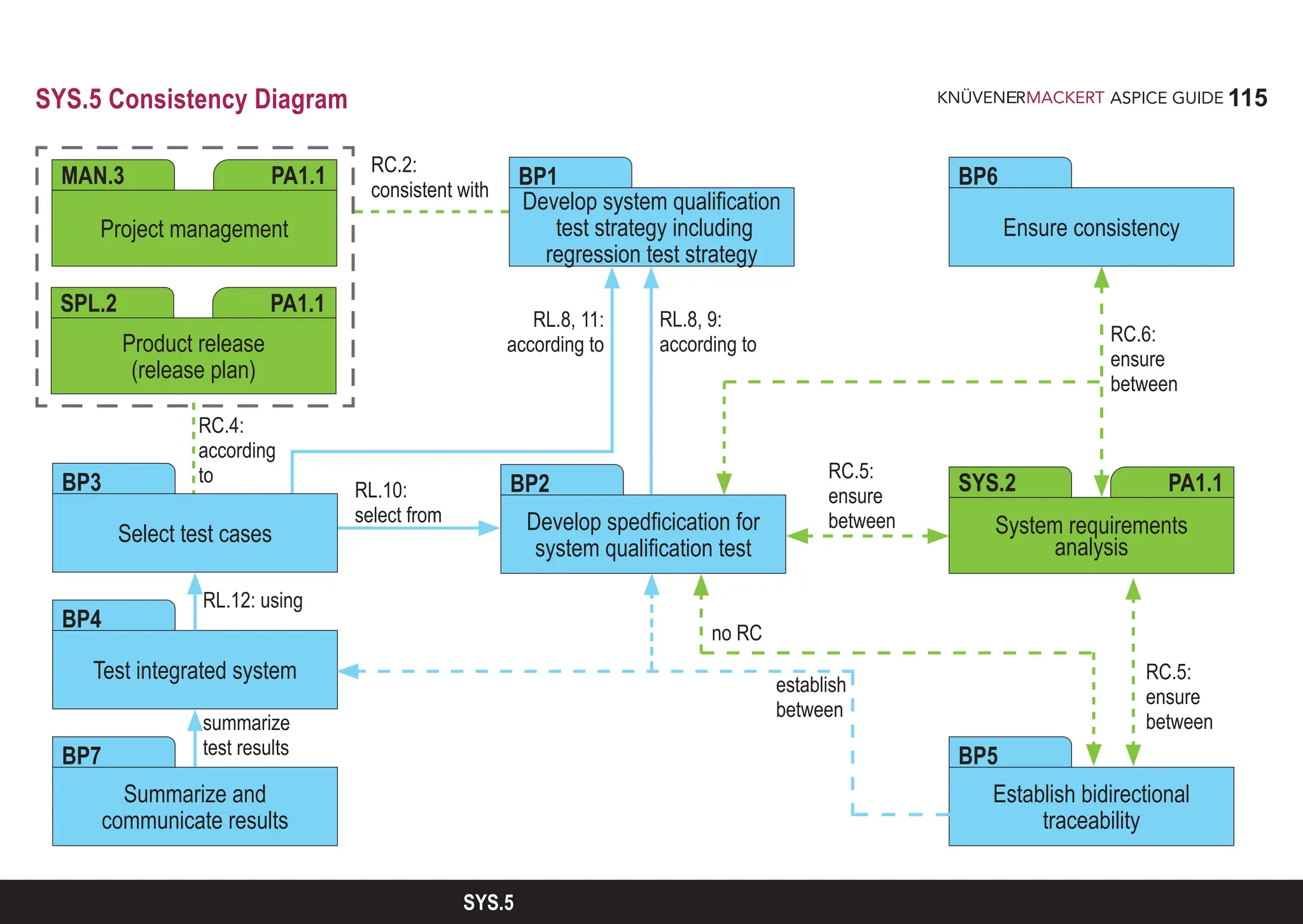
![116
ASPICE GUIDE
SWE.1 Software Requirements Analysis
The purpose of the Software Requirements Analysis Process is to transform the software related parts of the system requirements into
a set of software requirements.
Process outcomes – As a result of successful implementation of this process:
1. the software requirements to be allocated to the software elements of the system and their interfaces are defined;
2. software requirements are categorized and analyzed for correctness and verifiability;
3. the impact of software requirements on the operating environment is analyzed;
4. prioritization for implementing the software requirements is defined;
5. the software requirements are updated as needed;
6. consistency and bidirectional traceability are established between system requirements and software requirements; and consistency
and bidirectional traceability are established between system architectural design and software requirements;
7. the software requirements are evaluated for cost, schedule and technical impact; and
8. the software requirements are agreed and communicated to all affected parties.
Output work products
13-04 Communication record [OUTCOME 8] 15-01 Analysis report [OUTCOME 2, 3, 4, 7]
13-19 Review record [OUTCOME 6] 17-08 Interface requirements specification [OUTCOME 1, 3]
13-21 Change control record [OUTCOME 5,7] 17-11 Software requirements specification [OUTCOME 1]
13-22 Traceability record [OUTCOME 1,6] 17-50 Verification criteria [OUTCOME 2]](https://image.slidesharecdn.com/aspice-guide-km2021-04-240204182441-58722c47/75/ASPICE-Guide-KM2021-04-pdf-116-2048.jpg)
![117
ASPICE GUIDE
SWE.1 with 8 Base practices
BP 1
1
2
5
117
SWE.1
BP 2
3
Specify software requirements. Use the system requirements and the system architecture and changes to system
requirements and architecture to identify the required functions and capabilities of the software. Specify functional and
nonfunctional software requirements in a software requirements specification. [OUTCOME 1, 5, 7]
Application parameter influencing functions and capabilities are part of the system requirements.
In case of software development only, the system requirements and the system architecture refer to a given operating
environment (see also ). In that case, stakeholder requirements should be used as the basis for identifying the
required functions and capabilities of the software as well as for identifying application parameters influencing software
functions and capabilities.
Structure software requirements. Structure the software requirements in the software requirements specification by e.g.
• grouping to project relevant clusters,
• sorting in a logical order for the project,
• categorizing based on relevant criteria for the project,
• prioritizing according to stakeholder needs.
[OUTCOME 2, 4]
Prioritizing typically includes the assignment of software content to planned releases. Refer to SPL.2.BP1.
73: PLS.RC.4-5
76f: APA.RL.1, 3
120: SWE.1.RL.1-3
120: SWE.1.RL.4-5
121: SWE.1.RC.1
125: SWE.1.RL.10](https://image.slidesharecdn.com/aspice-guide-km2021-04-240204182441-58722c47/75/ASPICE-Guide-KM2021-04-pdf-117-2048.jpg)
![118
ASPICE GUIDE
BP 4
5
BP 3
4
SWE.1 with 8 Base practices 118
Analyze software requirements. Analyze the specified software requirements including their interdependencies to ensure
correctness, technical feasibility and verifiability, and to support risk identification. Analyze the impact on cost, schedule and
the technical impact. [OUTCOME 2, 7]
The analysis of impact on cost and schedule supports the adjustment of project estimates. Refer to MAN.3.BP5.
Analyze the impact on the operating environment. Analyze the impact that the software requirements will have on
interfaces of system elements and the operating environment. [OUTCOME 3, 7]
The operating environment is defined as the system in which the software executes (e.g. hardware, operating
system, etc.).
60: AGE.RC.3
121: SWE.1.RL.6, SWE.1.RC.2
125: SWE.1.RL.10
122: SWE.1.RC.3-4
125: SWE.1.RL.10](https://image.slidesharecdn.com/aspice-guide-km2021-04-240204182441-58722c47/75/ASPICE-Guide-KM2021-04-pdf-118-2048.jpg)
![119
ASPICE GUIDE
SWE.1
SWE.1 with 8 Base practices
6
BP 5
BP 6
7
119
Develop verification criteria. Develop the verification criteria for each software requirement that define the qualitative and
quantitative measures for the verification of a requirement. [OUTCOME 2, 7]
Verification criteria demonstrate that a requirement can be verified within agreed constraints and is typically used as the
input for the development of the software test cases or other verification measures that should demonstrate compliance
with the software requirements.
Verification which cannot be covered by testing is covered by SUP.2.
Establish bidirectional traceability. Establish bidirectional traceability between system requirements and software
requirements. Establish bidirectional traceability between the system architecture and software requirements. [OUTCOME 6]
Redundancy should be avoided by establishing a combination of these approaches that covers the project and the
organizational needs.
Bidirectional traceability supports coverage, consistency and impact analysis.
48: VEC.RL.1-2
74: PLS.RC.8
123: SWE.1.RL.7
125: SWE.1.RL.10
8
9
36ff: TAC.RC.1-4
41: TAC.RL.2-3
123ff: SWE.1.RL.8-10
125: SWE.1.RC.9-10](https://image.slidesharecdn.com/aspice-guide-km2021-04-240204182441-58722c47/75/ASPICE-Guide-KM2021-04-pdf-119-2048.jpg)
![120
ASPICE GUIDE
Ensure consistency. Ensure consistency between system requirements and software requirements. Ensure consistency
between the system architecture and software requirements. [OUTCOME 6]
Consistency is supported by bidirectional traceability and can be demonstrated by review records.
In case of software development only, the system requirements and system architecture refer to a given operating
environment (see also ). In that case, consistency and bidirectional traceability have to be ensured between
stakeholder requirements and software requirements.
Communicate agreed software requirements. Communicate the agreed software requirements and updates to software
requirements to all relevant parties. [OUTCOME 8]
SWE.1 with 8 Base practices
BP 7
BP 8
10
11
2
120
39f: TAC.RL.1, 4
41: TAC.RL.2-3
123ff: SWE.1.RL.8-12
233: CL2.RC.18
44: SAC.RL.1
46: SAC.RC.4-6
67: TPS.RC.2-3
125: SWE.1.RL.10
225: CL2.RC.9](https://image.slidesharecdn.com/aspice-guide-km2021-04-240204182441-58722c47/75/ASPICE-Guide-KM2021-04-pdf-120-2048.jpg)
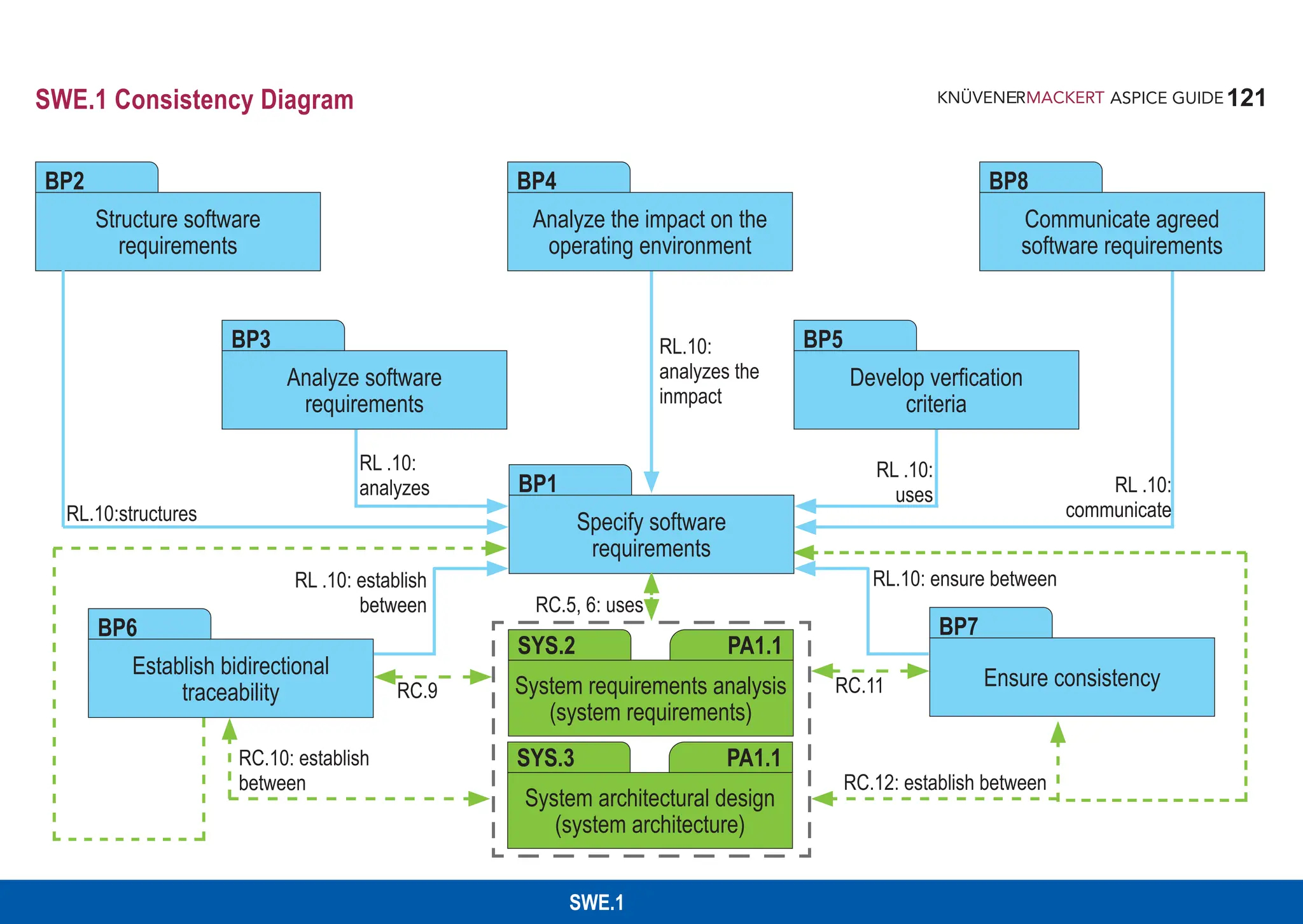
![122
ASPICE GUIDE
SWE.2 Software Architectural Design
The purpose of the Software Architectural Design Process is to establish an architectural design and to identify which software
requirements are to be allocated to which elements of the software, and to evaluate the software architectural design against
defined criteria.
Process outcomes – As a result of successful implementation of this process:
1. a software architectural design is defined that identifies the elements of the software;
2. the software requirements are allocated to the elements of the software;
3. the interfaces of each software element are defined;
4. the dynamic behavior and resource consumption objectives of the software elements are defined;
5. consistency and bidirectional traceability are established between software requirements and software architectural design; and
6. the software architectural design is agreed and communicated to all affected parties.
Output work products
04-04 Software architectural design [OUTCOME 1, 2, 3, 4, 5] 13-22 Traceability record [OUTCOME 5]
13-04 Communication record [OUTCOME 6] 17-08 Interface requirements specification [OUTCOME 3]
13-19 Review record [OUTCOME 5]](https://image.slidesharecdn.com/aspice-guide-km2021-04-240204182441-58722c47/75/ASPICE-Guide-KM2021-04-pdf-122-2048.jpg)
![123
ASPICE GUIDE
SWE.2
SWE.2 with 9 Base practices
BP1
1
BP2
BP3
123
Develop software architectural design. Develop and document the software architectural design that specifies the
elements of the software with respect to functional and non-functional software requirements. [OUTCOME 1]
The software is decomposed into elements across appropriate hierarchical levels down to the software components
(the lowest level elements of the software architectural design) that are described in the detailed design.
Allocate software requirements. Allocate the software requirements to the elements of the software architectural design.
[OUTCOME 2]
Define interfaces of software elements. Identify, develop and document the interfaces of each software element.
[OUTCOME 3]
61: AGE.RC.5-6
68: TPS.RC.4, 6
72: PLS.RC.2
128: SWE.2.RL.1-2
134: SWE.2.RC.3
129: SWE.2.RL.3
134: SWE.2.RL.8
68: TPS.RC.5
129: SWE.2.RL.4
134: SWE.2.RL.8](https://image.slidesharecdn.com/aspice-guide-km2021-04-240204182441-58722c47/75/ASPICE-Guide-KM2021-04-pdf-123-2048.jpg)
![124
ASPICE GUIDE
SWE.2 with 9 Base practices
BP6
124
BP4
2
3
130: SWE.2.RL.5
134: SWE.2.RL.8
131: SWE.2.RL.6
134: SWE.2.RL.8
Describe dynamic behavior. Evaluate and document the timing and dynamic interaction of software elements to meet
the required dynamic behavior of the system. [OUTCOME 4]
Dynamic behavior is determined by operating modes (e.g. start-up, shutdown, normal mode, calibration, diagnosis, etc.),
processes and process intercommunication, tasks, threads, time slices, interrupts, etc.
During evaluation of the dynamic behavior the target platform and potential loads on the target should be considered.
Define resource consumption objectives. Determine and document the resource consumption objectives
for all relevant elements of the software architectural design on the appropriate hierarchical level. [OUTCOME 4]
Resource consumption is typically determined for resources like Memory (ROM, RAM, external / internal EEPROM or
Data Flash), CPU load, etc.
Evaluate alternative software architectures. Define evaluation criteria for the architecture. Evaluate alternative software
architectures according to the defined criteria. Record the rationale for the chosen software architecture.
[OUTCOME 1, 2, 3, 4, 5]
Evaluation criteria may include quality characteristics (modularity, maintainability, expandability, scalability, reliability,
security realization and usability) and results of make-buy-reuse analysis.
5
132: SWE.2.RC.1
134: SWE.2.RL.8
BP5
4](https://image.slidesharecdn.com/aspice-guide-km2021-04-240204182441-58722c47/75/ASPICE-Guide-KM2021-04-pdf-124-2048.jpg)
![125
ASPICE GUIDE
Establish bidirectional traceability. Establish bidirectional traceability between software requirements and elements of the
software architectural design. [OUTCOME 5]
Bidirectional traceability covers allocation of software requirements to the elements of the software architectural design.
Bidirectional traceability supports coverage, consistency and impact analysis.
Ensure consistency. Ensure consistency between software requirements and the software architectural design.
[OUTCOME 1, 2, 5, 6]
Consistency is supported by bidirectional traceability and can be demonstrated by review records.
Communicate agreed software architectural design. Communicate the agreed software architectural design and updates
to software architectural design to all relevant parties. [OUTCOME 6]
6
BP7
7
8
BP8
BP9
SWE.2
SWE.2 with 9 Base practices
36ff: TAC.RC.1-4
41: TAC.RL.2-3
134: SWE.2.RL.8-9, SWE.2.RC.4
39: TAC.RL.1
40: TAC.RC.4
41: TAC.RL.2-3
134: SWE.2.RL.8, SWE.2.RC.5
233: CL2.RC.18
44: SAC.RL.1
46: SAC.RC.4-6
225: CL2.RC.9
125](https://image.slidesharecdn.com/aspice-guide-km2021-04-240204182441-58722c47/75/ASPICE-Guide-KM2021-04-pdf-125-2048.jpg)
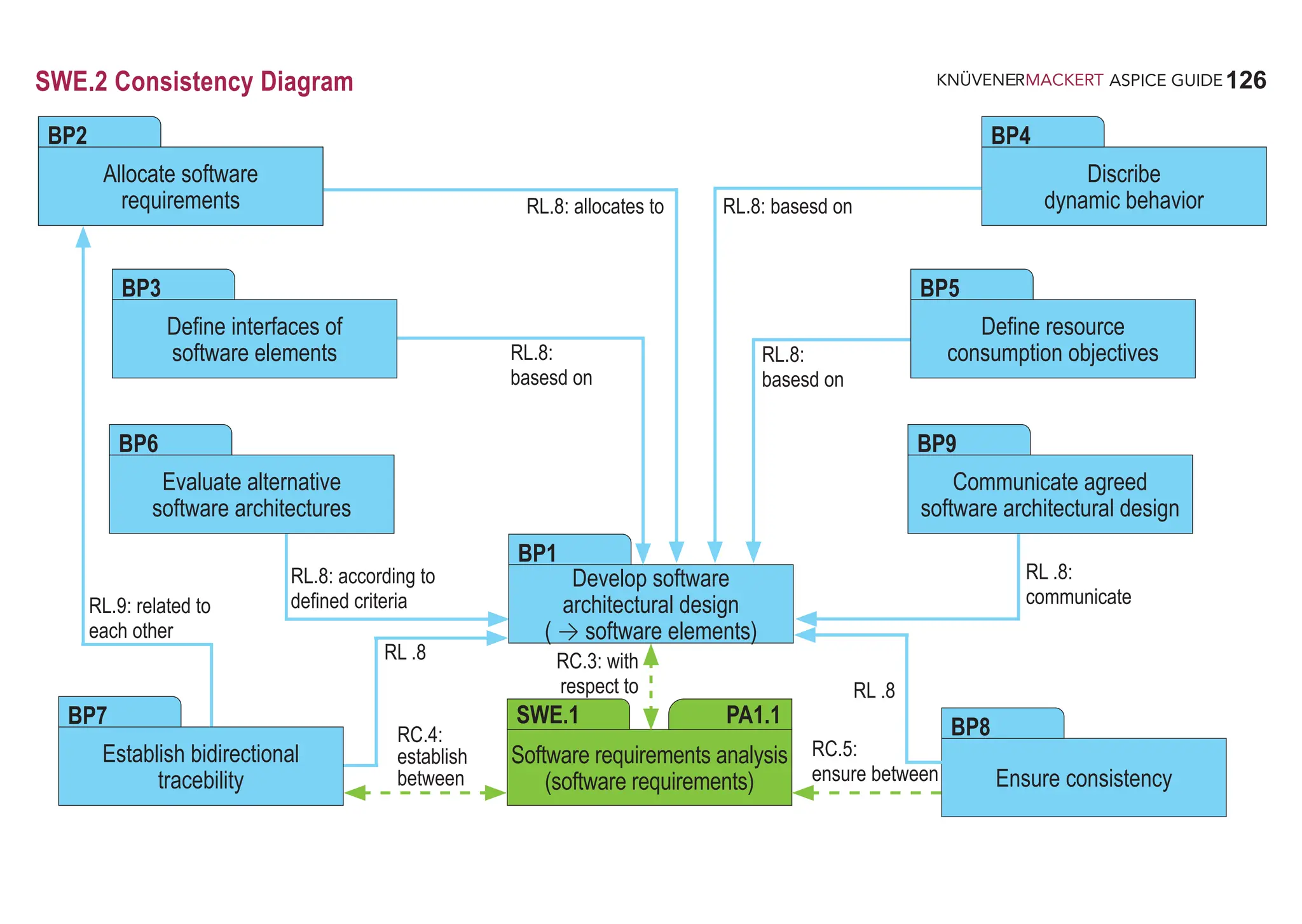

![128
ASPICE GUIDE
SWE.3 Software Detailed Design and Unit Construction
The purpose of the Software Detailed Design and Unit Construction Process is to provide an evaluated detailed design for the software
components and to specify and to produce the software units.
Process outcomes – As a result of successful implementation of this process:
1. a detailed design is developed that describes software units;
2. interfaces of each software unit are defined;
3. the dynamic behavior of the software units is defined;
4. consistency and bidirectional traceability are established between software requirements and software units; and consistency and
bidirectional traceability are established between software architectural design and software detailed design; and consistency and
bidirectional traceability are established between software detailed design and software units;
5. the software detailed design and the relationship to the software architectural design is agreed and communicated to all affected
parties; and
6. software units defined by the software detailed design are produced.
Output work products
04-05 Software detailed design [OUTCOME 1, 2, 3] 13-19 Review record [OUTCOME 4]
11-05 Software unit [OUTCOME 6] 13-22 Traceability record [OUTCOME 4]
13-04 Communication record [OUTCOME 5]](https://image.slidesharecdn.com/aspice-guide-km2021-04-240204182441-58722c47/75/ASPICE-Guide-KM2021-04-pdf-128-2048.jpg)
![129
ASPICE GUIDE
BP4
2
SWE.3 with 8 Base practices
BP1
BP2
129
SWE.3
Develop software detailed design. Develop a detailed design for each software component defined in the software
architectural design that specifies all software units with respect to functional and non-functional software requirements.
[OUTCOME 1]
Define interfaces of software units. Identify, specify and document the interfaces of each software unit. [OUTCOME 2]
Describe dynamic behavior. Evaluate and document the dynamic behavior of and the interaction between relevant
software units. [OUTCOME 3]
Not all software units have dynamic behavior to be described.
Evaluate software detailed design. Evaluate the software detailed design in terms of interoperability, interaction,
criticality, technical complexity, risks and testability. [OUTCOME 1,2,3,4]
The results of the evaluation can be used as input for software unit verification.
BP3
1
76: APA.RL.2
137: SWE.3.RL.1-2
143: SWE.3.RC.2-3
138: SWE.3.RL.3
143: SWE.3.RL.7
139: SWE.3.RL.4
143: SWE.3.RL.7
141: SWE.3.RL.5, SWE.3.RC.1
143: SWE.3.RL.7](https://image.slidesharecdn.com/aspice-guide-km2021-04-240204182441-58722c47/75/ASPICE-Guide-KM2021-04-pdf-129-2048.jpg)
![130
ASPICE GUIDE
BP6
BP5
SWE.3 with 8 Base practices 130
Establish bidirectional traceability. Establish bidirectional traceability between software requirements and software units.
Establish bidirectional traceability between the software architectural design and the software detailed design. Establish
bidirectional traceability between the software detailed design and software units. [OUTCOME 4]
Redundancy should be avoided by establishing a combination of these approaches that covers the project and the
organizational needs.
Bidirectional traceability supports coverage, consistency and impact analysis.
Ensure consistency. Ensure consistency between software requirements and software units. Ensure consistency between
the software architectural design, the software detailed design and software units. [OUTCOME 4]
Consistency is supported by bidirectional traceability and can be demonstrated by review records.
3
4
5
36ff: TAC.RC.1-4
41: TAC.RL.2-3
143: SWE.3.RL.7, SWE.3.RC.4-5
39: TAC.RL.1
40: TAC.RC.4
41: TAC.RL.2-3
57: MBD.RL.6
143: SWE.3.RL.7, SWE.3.RC.6-7
233: CL2.RC.18](https://image.slidesharecdn.com/aspice-guide-km2021-04-240204182441-58722c47/75/ASPICE-Guide-KM2021-04-pdf-130-2048.jpg)
![131
ASPICE GUIDE
SWE.3
SWE.3 with 8 Base practices
BP8
BP7
Communicate agreed software detailed design. Communicate the agreed software detailed design and updates to the
software detailed design to all relevant parties. [OUTCOME 5]
Develop software units. Develop and document the executable representations of each software unit according to the
software detailed design. [OUTCOME 6]
44: SAC.RL.1
46: SAC.RC.4-6
143: SWE.3.RL.7
225: CL2.RC.9
141ff: SWE.3.RL.6-7
131](https://image.slidesharecdn.com/aspice-guide-km2021-04-240204182441-58722c47/75/ASPICE-Guide-KM2021-04-pdf-131-2048.jpg)
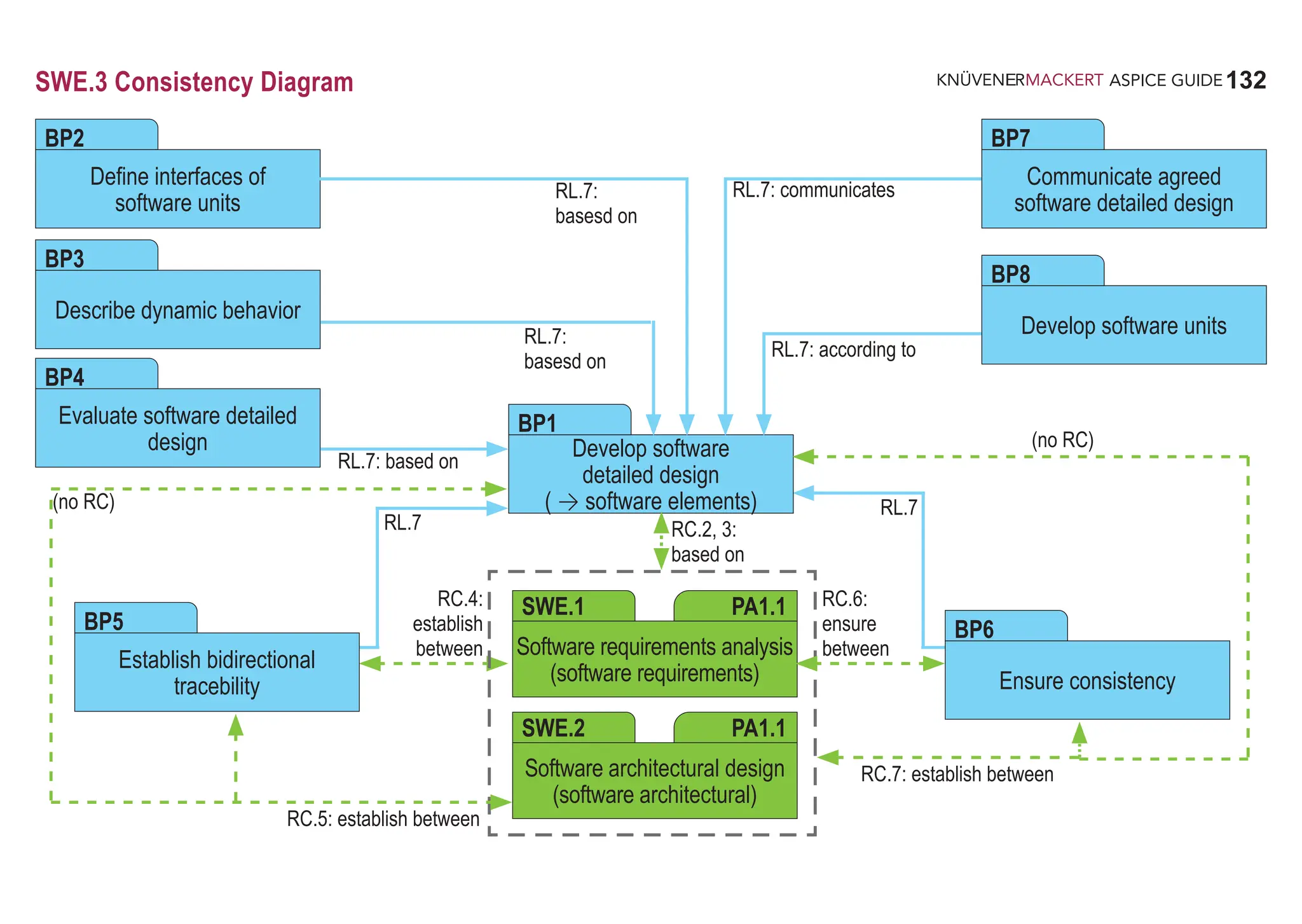

![134
ASPICE GUIDE
SWE.4 Software Unit Verification
The purpose of the Software Unit Verification Process is to verify software units to provide evidence for compliance of the software
units with the software detailed design and with the non-functional software requirements.
Process outcomes – As a result of successful implementation of this process:
1. a software unit verification strategy including regression strategy is developed to verify the software units;
2. criteria for software unit verification are developed according to the software unit verification strategy that are suitable to provide
evidence for compliance of the software units with the software detailed design and with the non-functional software requirements;
3. software units are verified according to the software unit verification strategy and the defined criteria for software unit verification
and the results are recorded;
4. consistency and bidirectional traceability are established between software units, criteria for verification and verification results; and
5. results of the unit verification are summarized and communicated to all affected parties.
Output work products
08-50 Test specification E [OUTCOME 2] 13-22 Traceability record [OUTCOME 4]
08-52 Test plan [OUTCOME 1] 13-25 Verification results [OUTCOME 3, 5]
13-04 Communication record [OUTCOME 5] 13-50 Test result [OUTCOME 3, 5]
13-19 Review record [OUTCOME 3, 4] 15-01 Analysis report [OUTCOME 3]](https://image.slidesharecdn.com/aspice-guide-km2021-04-240204182441-58722c47/75/ASPICE-Guide-KM2021-04-pdf-134-2048.jpg)
![135
ASPICE GUIDE
BP2
2
3
SWE.4 with 7 Base practices
Develop software unit verification strategy including regression strategy. Develop a strategy for verification of the
software units including regression strategy for re-verification if a software unit is changed. The verification strategy shall define
how to provide evidence for compliance of the software units with the software detailed design and with the non-functional
requirements. [OUTCOME 1]
Possible techniques for unit verification include static/dynamic analysis, code reviews, unit testing etc.
Develop criteria for unit verification. Develop criteria for unit verification that are suitable to provide evidence for
compliance of the software units, and their interactions within the component, with the software detailed design and with
the non-functional requirements according to the verification strategy. For unit testing, criteria shall be defined in a unit test
specification. [OUTCOME 2]
Possible criteria for unit verification include unit test cases, unit test data, static verification, coverage goals and coding
standards such as the MISRA rules.
The unit test specification may be implemented e.g. as a script in an automated test bench.
BP1
1
135
SWE.4
51ff: SAP.RL.1-4
62: AGE.RC.7
81: APA.RL.8
145: SWE.4.RL.1-2
148: SWE.4.RL.7
149: SWE.4.RC.1-2](https://image.slidesharecdn.com/aspice-guide-km2021-04-240204182441-58722c47/75/ASPICE-Guide-KM2021-04-pdf-135-2048.jpg)
![136
ASPICE GUIDE
4
5
SWE.4 with 7 Base practices 136
BP3
BP4
BP5
7
6
Perform static verification of software units. Verify software units for correctness using the defined criteria for verification.
Record the results of the static verification. [OUTCOME 3]
Static verification may include static analysis, code reviews, checks against coding standards and guidelines, and other
techniques.
See SUP.9 for handling of non-conformances.
Test software units. Test software units using the unit test specification according to the software unit verification strategy.
Record the test results and logs. [OUTCOME 3]
See SUP.9 for handling of non-conformances.
Establish bidirectional traceability. Establish bidirectional traceability between software units and static verification results.
Establish bidirectional traceability between the software detailed design and the unit test specification. Establish bidirectional
traceability between the unit test specification and unit test results. [OUTCOME 4]
Bidirectional traceability supports coverage, consistency and impact analysis.
57: MBD.RL.7-8, 10
62: AGE.RC.11
145: SWE.4.RL.3-6
148: SWE.4.RL.8
57: MBD.RL.9, 11
145ff: SWE.4.RL.3-7, 9
36ff: TAC.RC.1-4
149: SWE.4.RC.3](https://image.slidesharecdn.com/aspice-guide-km2021-04-240204182441-58722c47/75/ASPICE-Guide-KM2021-04-pdf-136-2048.jpg)
![137
ASPICE GUIDE
SWE.4
SWE.4 with 7 Base practices
Ensure consistency. Ensure consistency between the software detailed design and the unit test specification. [OUTCOME 4]
Consistency is supported by bidirectional traceability and can be demonstrated by review records.
Summarize and communicate results. Summarize the unit test results and static verification results and communicate
them to all affected parties. [OUTCOME 5]
Providing all necessary information from the test case execution in a summary enables other parties to judge the
consequences.
BP6
BP7
8
9
137
39: TAC.RL.1
40: TAC.RC.4
149: SWE.4.RC.4
233: CL2.RC.18
43ff: SAC.RC.1-6
148: SWE.4.RL.10-11
225: CL2.RC.10](https://image.slidesharecdn.com/aspice-guide-km2021-04-240204182441-58722c47/75/ASPICE-Guide-KM2021-04-pdf-137-2048.jpg)
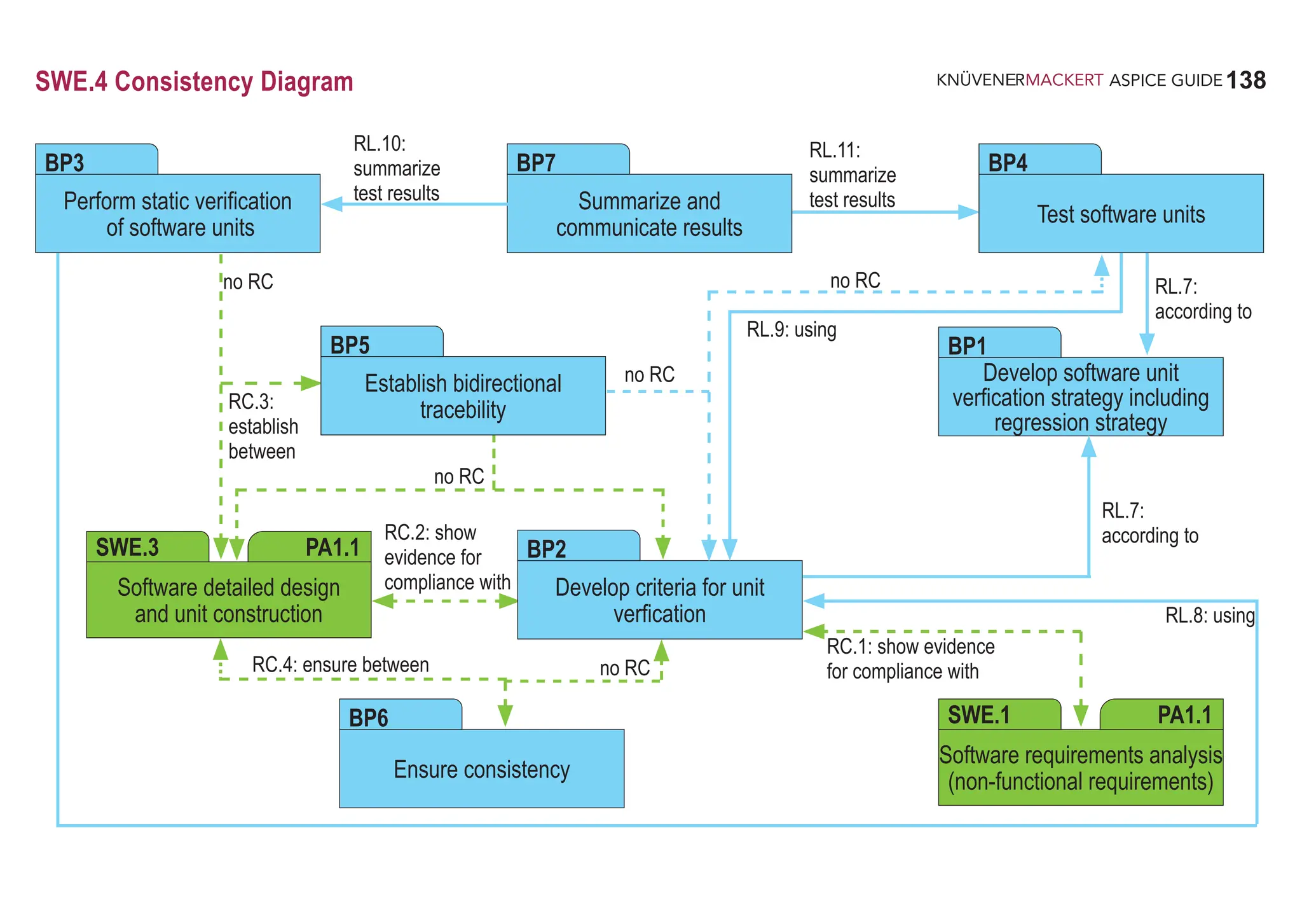

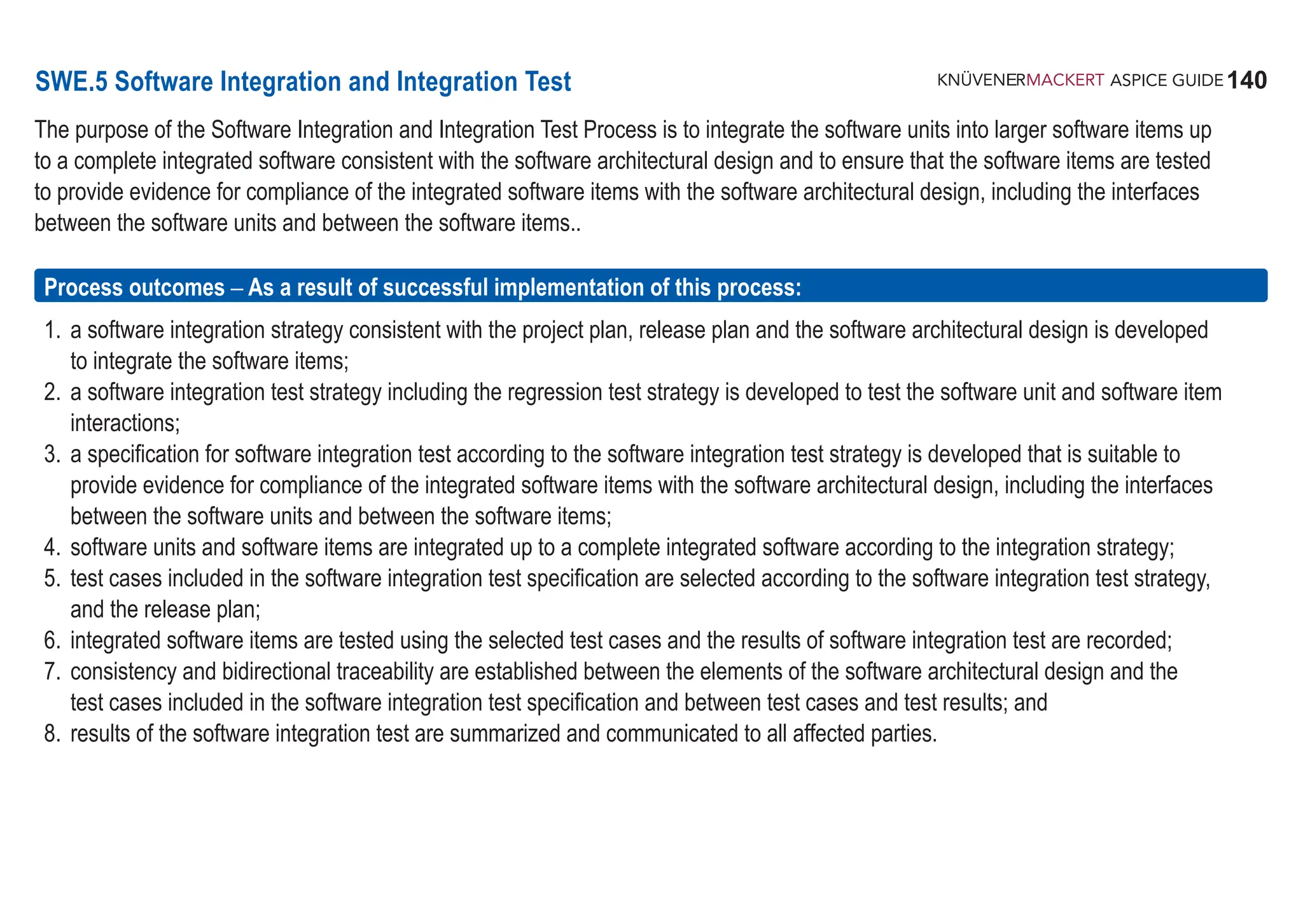
![141
ASPICE GUIDE
Output work products
01-03 Software item [OUTCOME 4] 13-19 Review record [OUTCOME 7]
01-50 Integrated software [OUTCOME 4] 13-22 Traceability record [OUTCOME 7]
08-50 Test specification [OUTCOME 3,5] 13-50 Test result [OUTCOME 6, 8]
08-52 Test plan [OUTCOME 1,2] 17-02 Build list [OUTCOME 4, 7]
13-04 Communication record [OUTCOME 8]
SWE.5 with 9 Base practices
BP1
141
SWE.5
51ff: SAP.RL.1-4
62: AGE.RC.8
65: DID.RL.10
150: SWE.5.RL.1
157: SWE.5.RC.2-3
BP2
51ff: SAP.RL.1-4
81: APA.RL.8
152: SWE.5.RL.2-3
Develop software integration strategy. Develop a strategy for integrating software items consistent with the project plan
and release plan. Identify software items based on the software architectural design and define a sequence for integrating
them. [OUTCOME 1]
Develop software integration test strategy including regression test strategy. Develop a strategy for testing the
integrated software items following the integration strategy. This includes a regression test strategy for re-testing integrated
software items if a software item is changed. [OUTCOME 2]](https://image.slidesharecdn.com/aspice-guide-km2021-04-240204182441-58722c47/75/ASPICE-Guide-KM2021-04-pdf-141-2048.jpg)
![142
ASPICE GUIDE
BP4
Develop specification for software integration test. Develop the test specification for software integration test including
the test cases according to the software integration test strategy for each integrated software item. The test specification
shall be suitable to provide evidence for compliance of the integrated software items with the software architectural design.
[OUTCOME 3]
Compliance to the architectural design means that the specified integration tests are suitable to prove that the
interfaces between the software units and between the software items fulfill the specification given by the software
architectural design.
The software integration test cases may focus on
• the correct dataflow between software items
• the timelines and timing dependencies of dataflow between software items
• the correct interpretation of data by all software items using an interface
• the dynamic interaction between software items
• the compliance to resource consumption objectives of interfaces
Integrate software units and software items. Integrate the software units to software items and software items to integrated
software according to the software integration strategy. [OUTCOME 4]
SWE.5 with 9 Base practices 142
BP3
1
2
70: TPS.RC.11
152: SWE.5.RL.4
156: SWE.5.RL.9, SWE.5.RL.11
157: SWE.5.RC.4
156: SWE.5.RL.12](https://image.slidesharecdn.com/aspice-guide-km2021-04-240204182441-58722c47/75/ASPICE-Guide-KM2021-04-pdf-142-2048.jpg)
![143
ASPICE GUIDE
SWE.5 with 9 Base practices 143
SWE.5
Select test cases. Select test cases from the software integration test specification. The selection of test cases shall have
sufficient coverage according to the software integration test strategy and the release plan. [OUTCOME 5]
Perform software integration test. Perform the software integration test using the selected test cases. Record the
integration test results and logs. [OUTCOME 6]
See SUP.9 for handling of non-conformances.
The software integration test may be supported by using hardware debug interfaces or simulation environments
(e.g. Software-in-the-Loop-Simulation).
Establish bidirectional traceability. Establish bidirectional traceability between elements of the software architectural
design and test cases included in the software integration test specification. Establish bidirectional traceability between test
cases included in the software integration test specification and software integration test results. [OUTCOME 7]
Bidirectional traceability supports coverage, consistency and impact analysis.
BP5
BP7
5
BP6
4
3
153: SWE.5.RL.5
153: SWE.5.RC.1
156: SWE.5.RL.9
156: SWE.5.RL.13-14
157: SWE.5.RC.5
70: TPS.RC.12
153f: SWE.5.RL.6-8
156: SWE.5.RL.15
36ff: TAC.RC.1-4
157: SWE.5.RC.6](https://image.slidesharecdn.com/aspice-guide-km2021-04-240204182441-58722c47/75/ASPICE-Guide-KM2021-04-pdf-143-2048.jpg)
![144
ASPICE GUIDE
BP8
BP9
SWE.5 with 9 Base practices
Ensure consistency. Ensure consistency between elements of the software architectural design and test cases included in
the software integration test specification. [OUTCOME 7]
Consistency is supported by bidirectional traceability and can be demonstrated by review records.
Summarize and communicate results. Summarize the software integration test results and communicate them to all
affected parties. [OUTCOME 8]
Providing all necessary information from the test case execution in a summary enables other parties to judge the
consequences.
6
7
144
39: TAC.RL.1
40: TAC.RC.4
157: SWE.5.RC.7
233: CL2.RC.18
43ff: SAC.RC.1-6, SAC.RL.2
225: CL2.RC.10](https://image.slidesharecdn.com/aspice-guide-km2021-04-240204182441-58722c47/75/ASPICE-Guide-KM2021-04-pdf-144-2048.jpg)
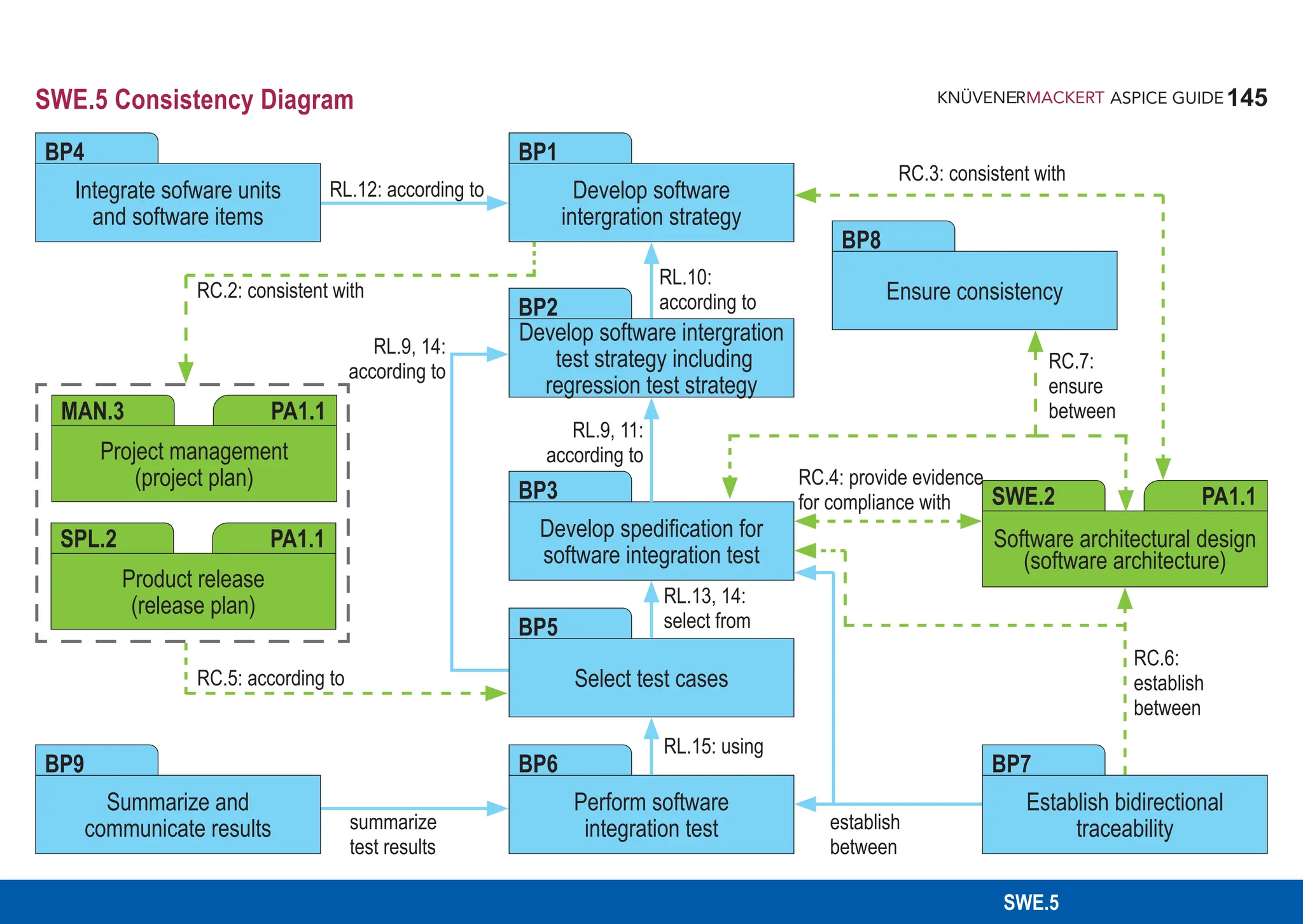
![146
ASPICE GUIDE
SWE.6 Software Qualification Test
The purpose of the Software Qualification Test Process is to ensure that the integrated software is tested to provide evidence for
compliance with the software requirements.
Process outcomes – As a result of successful implementation of this process:
1. a software qualification test strategy including regression test strategy consistent with the project plan and release plan is
developed to test the integrated software;
2. a specification for software qualification test of the integrated software according to the software qualification test strategy is
developed that is suitable to provide evidence for compliance with the software requirements;
3. test cases included in the software qualification test specification are selected according to the software qualification test strategy
and the release plan;
4. the integrated software is tested using the selected test cases and the results of software qualification test are recorded;
5. consistency and bidirectional traceability are established between software requirements and software qualification test
specification including test cases and between test cases and test results; and
6. results of the software qualification test are summarized and communicated to all affected parties.
Output work products
08-50 Test specification [OUTCOME 2, 3] 13-19 Review record [OUTCOME 5]
08-52 Test plan [OUTCOME 1] 13-22 Traceability record [OUTCOME 5]
13-04 Communication record [OUTCOME 6] 13-50 Test result [OUTCOME 4, 6]](https://image.slidesharecdn.com/aspice-guide-km2021-04-240204182441-58722c47/75/ASPICE-Guide-KM2021-04-pdf-146-2048.jpg)
![147
ASPICE GUIDE
BP2
SWE.6 with 7 Base practices
BP1
147
SWE.6
Develop software qualification test strategy including regression test strategy. Develop a strategy for software
qualification testing consistent with the project plan and the release plan. This includes a regression test strategy for
re-testing the integrated software if a software item is changed. [OUTCOME 1]
Develop specification for software qualification test. Develop the specification for software qualification test including
test cases based on the verification criteria, according to the software test strategy. The test specification shall be suitable
to provide evidence for compliance of the integrated software with the software requirements. [OUTCOME 2]
Select test cases. Select test cases from the software test specification. The selection of test cases shall have sufficient
coverage according to the software test strategy and the release plan. [OUTCOME 3]
51ff: SAP.RL.1-4
62: AGE.RC.9
74: PLS.RC.7
81: APA.RL.8
159: SWE.6.RL.1-2
163: SWE.6.RC.2
BP3
159: SWE.6.RL.3
163: SWE.6.RL.8-9
164: SWE.6.RC.3
160: SWE.6.RL.4, SWE.6.RC.1
163: SWE.6.RL.8, 10-11
164: SWE.6.RC.4](https://image.slidesharecdn.com/aspice-guide-km2021-04-240204182441-58722c47/75/ASPICE-Guide-KM2021-04-pdf-147-2048.jpg)
![148
ASPICE GUIDE
BP4
1
BP5
BP6
SWE.6 with 7 Base practices 148
Test integrated software. Test the integrated software using the selected test cases. Record the software test results and
logs. [OUTCOME 4]
See SUP.9 for handling of non-conformances.
Establish bidirectional traceability. Establish bidirectional traceability between software requirements and test cases
included in the software qualification test specification. Establish bidirectional traceability between test cases included in the
software qualification test specification and software qualification test results. [OUTCOME 5]
Bidirectional traceability supports coverage, consistency and impact analysis.
Ensure consistency. Ensure consistency between software requirements and test cases included in the software qualification
test specification. [OUTCOME 5]
Consistency is supported by bidirectional traceability and can be demonstrated by review records.
.
2
3
160f: SWE.6.RL.5-7
163: SWE.6.RL.12
36ff: TAC.RC.1-4
164: SWE.6.RC.5
39: TAC.RL.1
40: TAC.RC.4
164: SWE.6.RC.6
233: CL2.RC.18](https://image.slidesharecdn.com/aspice-guide-km2021-04-240204182441-58722c47/75/ASPICE-Guide-KM2021-04-pdf-148-2048.jpg)
![149
ASPICE GUIDE
SWE.6
BP7
4
43ff: SAC.RC.1-6
225: CL2.RC.10
SWE.6 with 7 Base practices 149
Summarize and communicate results. Summarize the software qualification test results and communicate them to all
affected parties. [OUTCOME 6]
Providing all necessary information from the test case execution in a summary enables other parties to judge the consequences](https://image.slidesharecdn.com/aspice-guide-km2021-04-240204182441-58722c47/75/ASPICE-Guide-KM2021-04-pdf-149-2048.jpg)
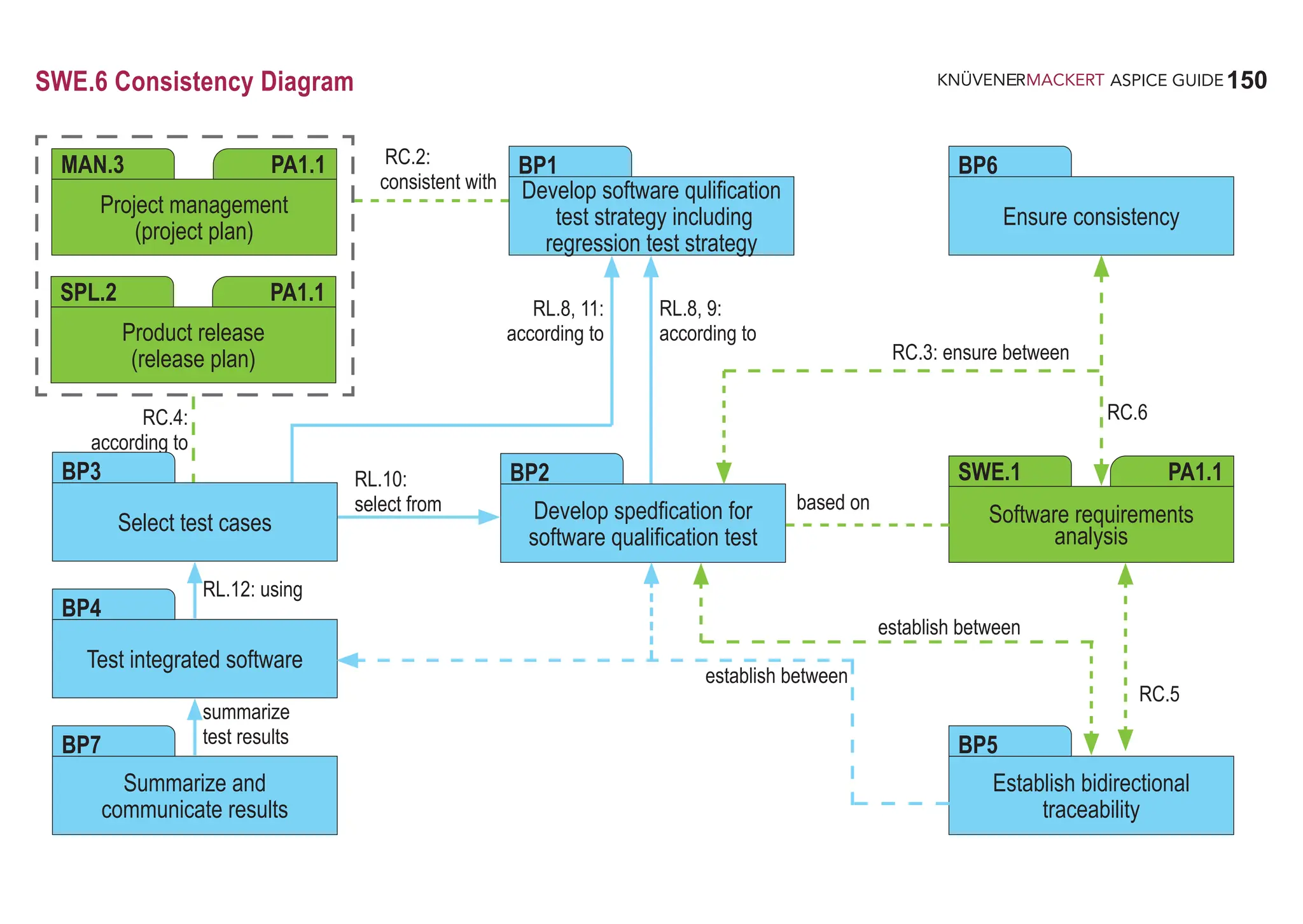

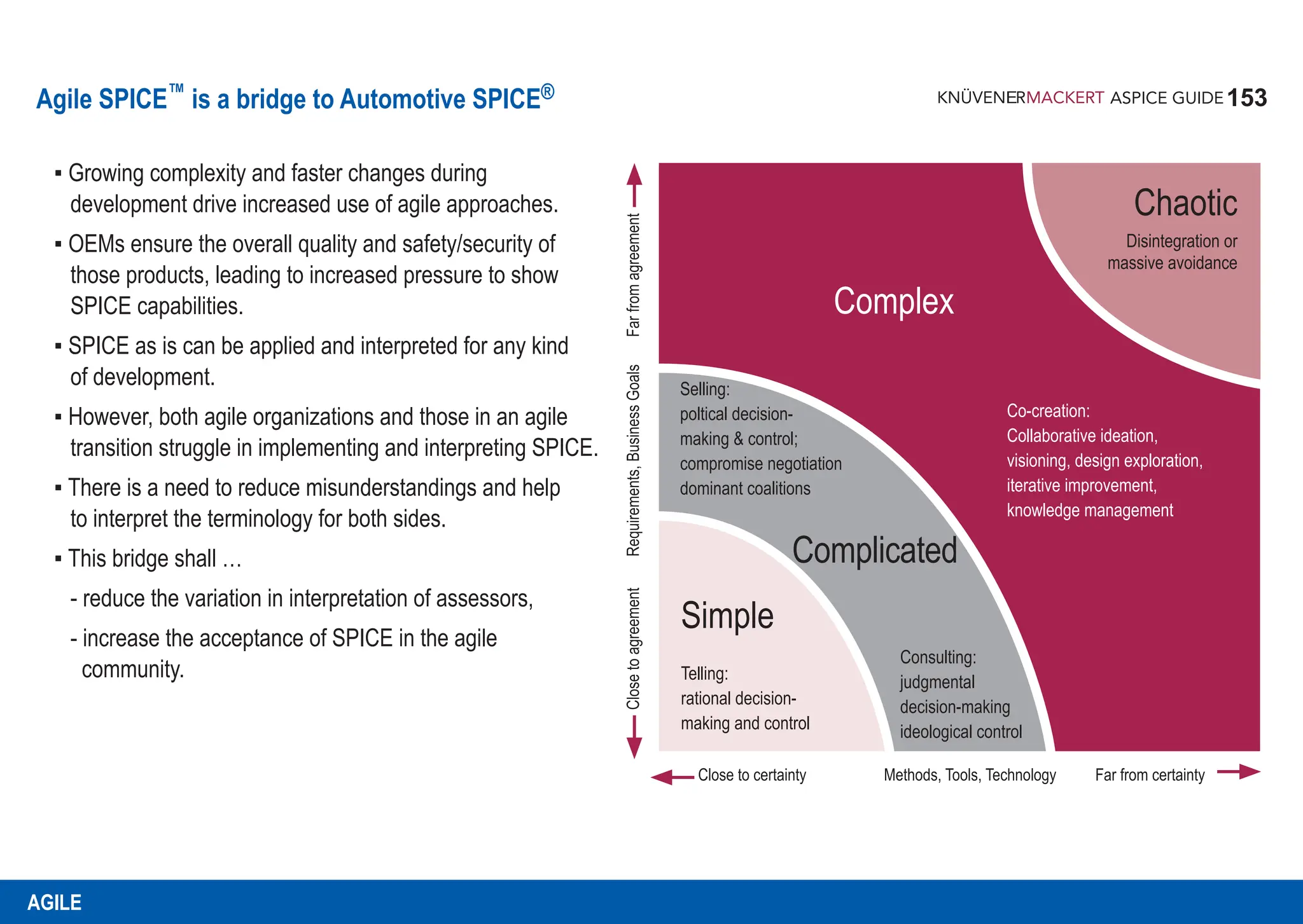
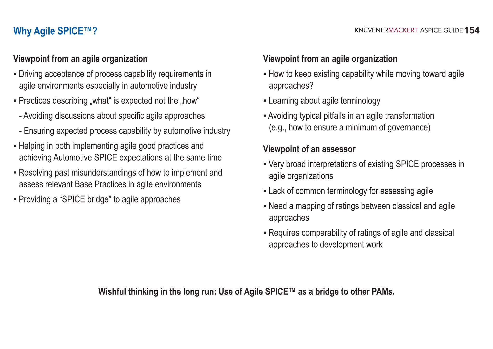
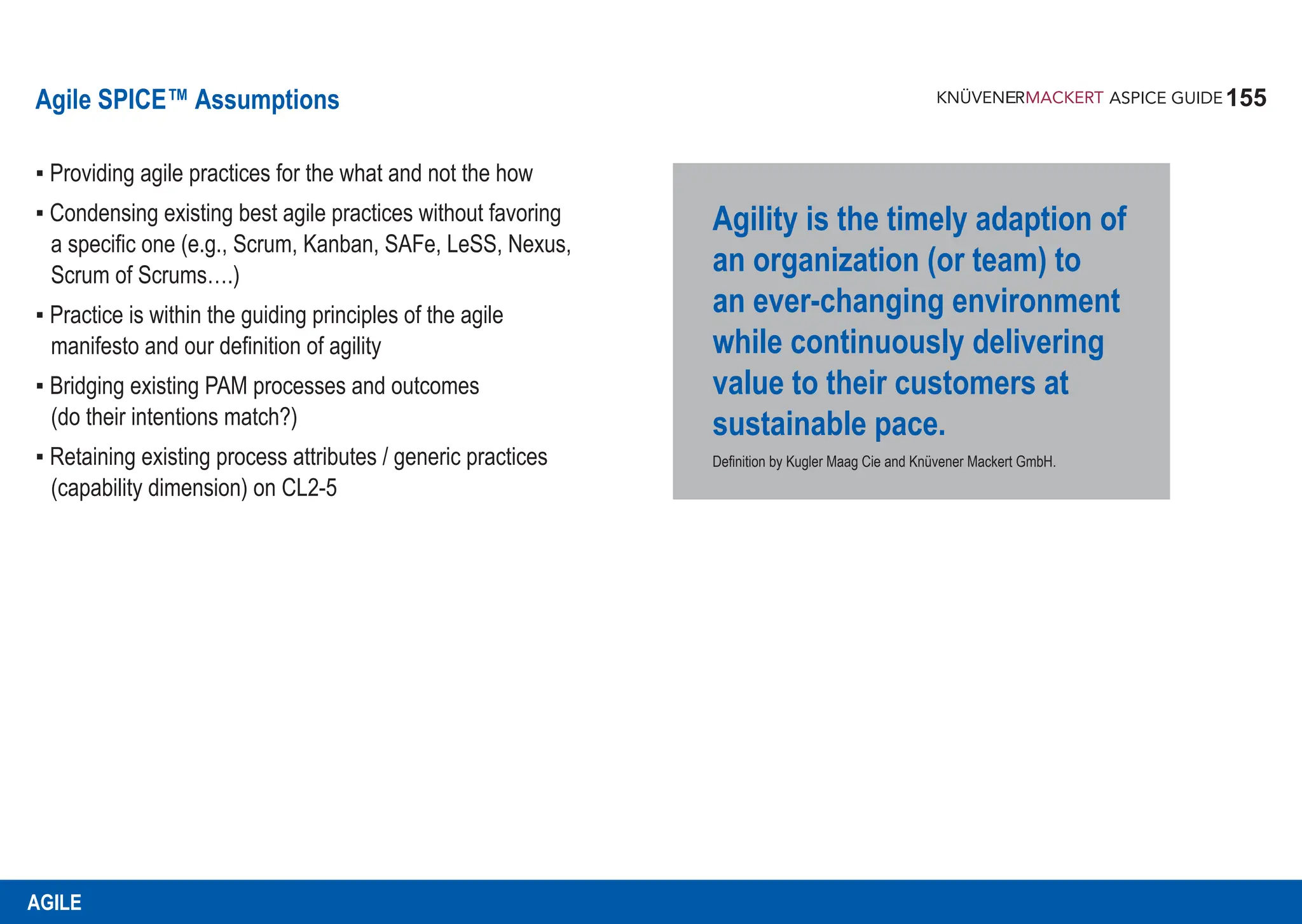
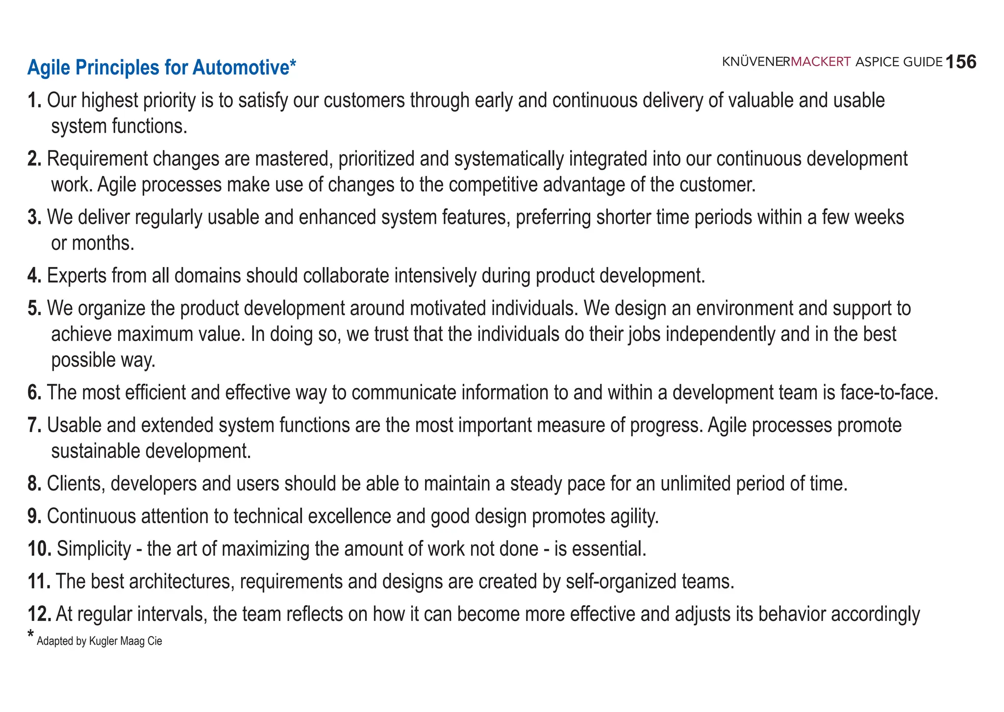
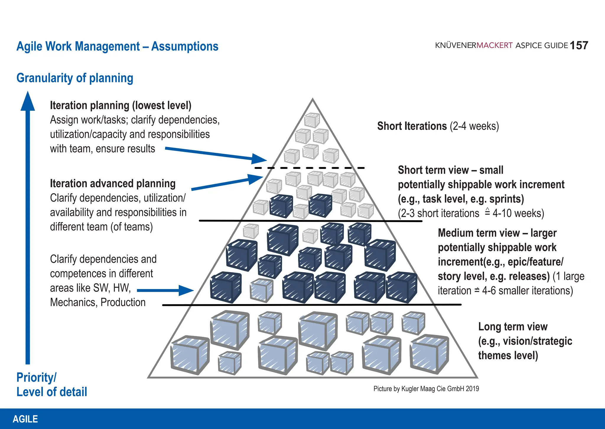
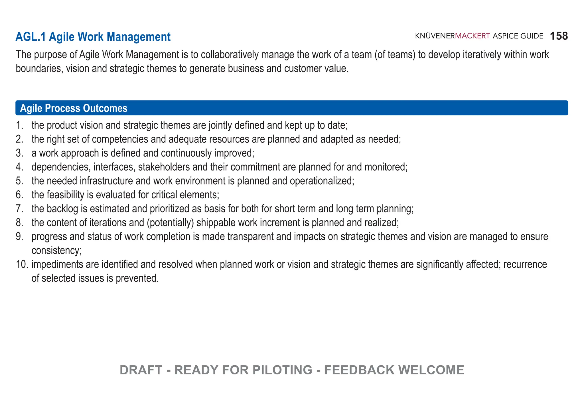
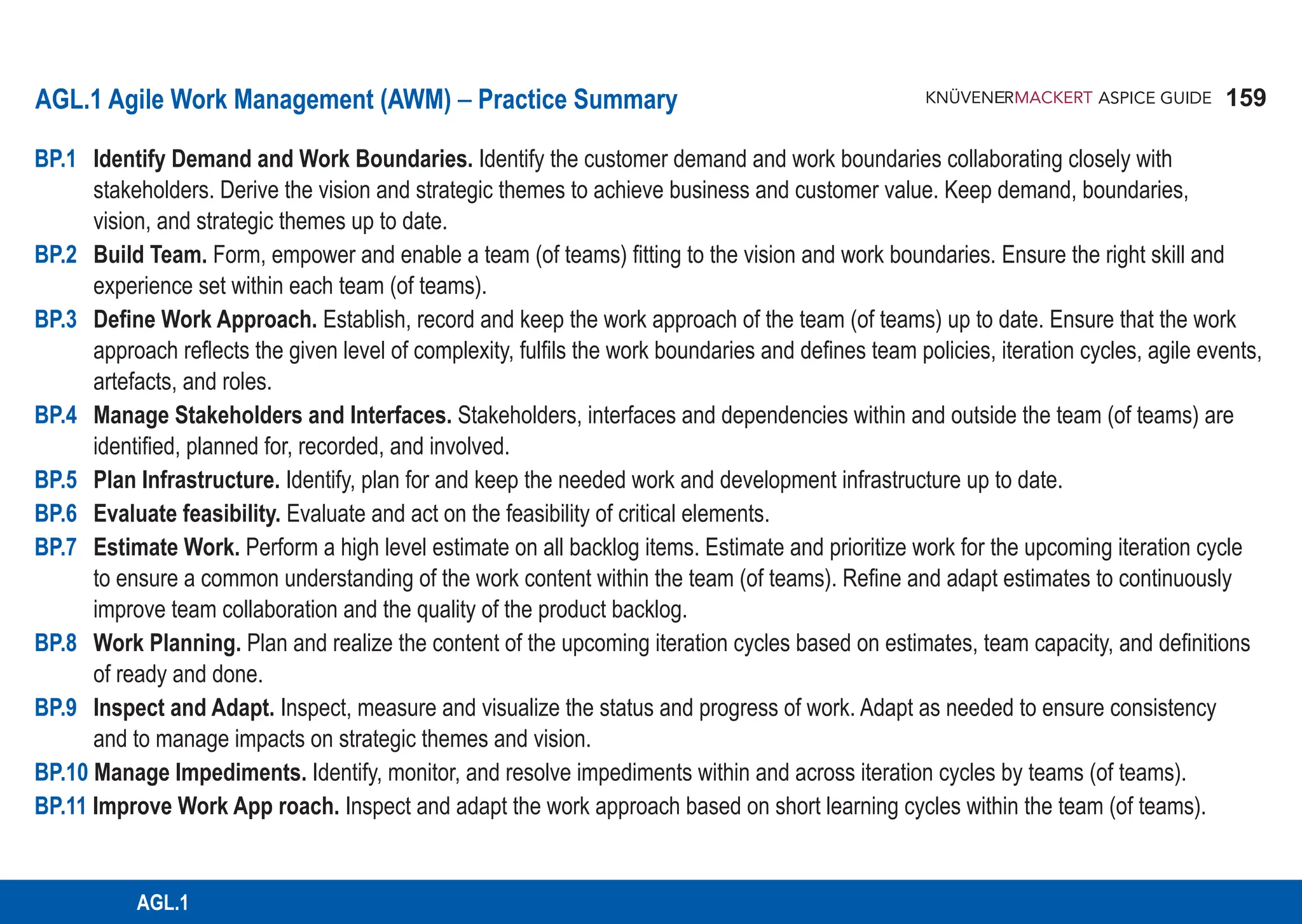
![160
ASPICE GUIDE
160
AGL.1 with 11 Base practices
Identify Demand and Work Boundaries. Identify the customer demand and work boundaries collaborating closely with
stakeholders. Derive the vision and strategic themes linked to business and customer value. Keep demand, boundaries, vision,
and strategic themes up to date. [OUTCOME 1]
Notes & Definitions:
▪ Collaboration can be internal and external as well as across organizations; e.g., within a program,
product line or organization, and together with (multiple) customers and suppliers.
▪ A customer demand is a recorded customer requirement or statement on the problem to be solved.
▪ A vision defines the product capabilities potentially leading to a successful solution.
▪ Strategic themes are unique selling propositions related both to vision of the product and its quality criteria.
They typically run across iterations and address a mid and long term perspective.
▪ Vision and strategic themes are typically the result of requirements engineering activities.
▪ A customer can be a stakeholder within (e.g., product management) or external to the organization (an individual customer)
▪ Boundaries can include out of scope, system context, solution space, link to feasibility, organizational constraints and
business objectives, platform and product line constraints as well as regulatory requirements.
▪ Ensure agreement with stakeholders on change mechanism for changes to the demand and
boundaries.
Agile Work Products: Product backlog, Demand statement (e.g. includes agreed stakeholder goals),
Boundaries, Vision and strategic themes
Supporting Agile Principles 1, 2, 4, 10, 11
BP1
DRAFT - READY FOR PILOTING - FEEDBACK WELCOME](https://image.slidesharecdn.com/aspice-guide-km2021-04-240204182441-58722c47/75/ASPICE-Guide-KM2021-04-pdf-160-2048.jpg)
![161
ASPICE GUIDE 161
Base practices
Build Team. Form, empower and enable a team (of teams) fitting to the vision and work boundaries. Ensure the right skill
and experience set within each team (of teams). [OUTCOME 2]
Notes & Definitions:
▪ Self organization is a guiding principle for founding an agile team (of teams) and their efficient performance.
▪ Teams of teams are used for larger scopes using a fitting agile scaling approach for teams.
▪ In scaling approaches all teams need to agree on ground rules to ensure a common purpose.
▪ Best performing teams are typically stable in composition and are working at a sustainable pace.
▪ Team building includes defined ground rules for collaboration within a team (of teams).
▪ Empowerment is a conscious delegation of decision authority to a team (of teams).
▪ Enablement ensures the right skills and experience set within a team (of teams) including needed training.
▪ Responsibility for technical releases and product liability must be defined.
Agile Work Products: Team setup, Work approach, Training plans and records, Skill profiles
Supporting Agile Principles 4, 5, 6, 8, 9, 11, 12
BP2
AGL.1
DRAFT - READY FOR PILOTING - FEEDBACK WELCOME](https://image.slidesharecdn.com/aspice-guide-km2021-04-240204182441-58722c47/75/ASPICE-Guide-KM2021-04-pdf-161-2048.jpg)
![162
ASPICE GUIDE
Define work approach. Establish, record and keep the work approach of the team (of teams) up to date. Ensure that the
work approach reflects the given level of complexity, fulfils the work boundaries and defines team policies, iteration cycles,
agile events, artefacts, and roles. [OUTCOME 3]
Notes & Definitions:
▪ Typically, agility is based on the pull principle as well as on limiting the amount of work in progress and on reducing
multi tasking.
▪ The Definition of Done (DoD) is a build in quality measure containing minimum, agreed to and recorded set of criteria
upon which a task or increment is considered to be done.
▪ The Definition of Ready (DoR) is a build in quality measure containing minimum, agreed to and recorded set of
criteria upon which a content is considered as ready to be pulled.
▪ Typical team (of teams) policies include Definitions of Ready and Done based on quality criteria.
▪ Stakeholder requirements for DoD and DoR include quality requirements, and possibly regulatory requirements imposed
by safety or security considerations.
▪ An agile approach often encompasses a whole product lifecycle and a clear alignment with the customer work approach.
▪ Typically, there is an agreement in place with the customer on the chosen agile approach and how delivered work is
accepted for each shippable work increment.
▪ If an iteration based approach has been chosen, iterations must be in line with t he chosen agile approach and is
influenced by the customer and technical feasibility as well as safety and security aspects.
Agile Work Products: Work approach, Definition of Done (DoD), Definition of Ready (DoR)
Supporting Agile Principles 2, 4, 5, 7, 8, 9, 10, 11
Base practices
BP3
162
DRAFT - READY FOR PILOTING - FEEDBACK WELCOME](https://image.slidesharecdn.com/aspice-guide-km2021-04-240204182441-58722c47/75/ASPICE-Guide-KM2021-04-pdf-162-2048.jpg)
![163
ASPICE GUIDE
AGL.1
Manage Stakeholders and interfaces. Stakeholders, interfaces and dependencies within and outside the team (of
teams) are identified, planned for, recorded and involved. [OUTCOME 4]
Notes & Definitions:
▪ Dependencies and interfaces include both technical and organizational ones:
▪ technical: e.g., among major architectural elements or safety/security related activities/roles;
▪ organizational: e.g., to other teams/stakeholders and between different iteration cycles;
▪ Supplied products or services: e.g. from suppliers or from customers.
▪ Critical dependencies should be identified from the start, their sequence identified, and their status tracked
across multiple iteration cycles. The elements of the backlog typically contain a path to address them.
▪ Stakeholder involvement includes tracking the commitment of involved and affected parties as well as ensuring the
active involvement of stakeholders.
▪ Maintain communication records for all interfaces. Continuously verify the necessity of all interfaces and remove
unnecessary interfaces.
▪ In case of mixed agile and classical approaches, e.g., on system and other discipline level, clearly define how
different approaches integrate and synchronize.
▪ Agile practitioners are typically organized in communities of practice (CoP, self organizing networks).
Agile Work Products: Agile work approach (containing e.g. communication and meeting mechanisms,
technical and organizational interfaces and dependencies), Product backlog
Supporting Agile Principles 2, 4, 5, 12
Base practices
BP4
163
DRAFT - READY FOR PILOTING - FEEDBACK WELCOME](https://image.slidesharecdn.com/aspice-guide-km2021-04-240204182441-58722c47/75/ASPICE-Guide-KM2021-04-pdf-163-2048.jpg)
![164
ASPICE GUIDE
164
Plan Infrastructure. Identify, plan for and keep the needed work and development infrastructure up to date.
[OUTCOME 5]
Notes & Definitions:
▪ Infrastructure typically includes but is not limited to an engineering tool chain, ticketing and backlog database,
verification and integration environment, communication and collaboration tools, physical and online workspaces,
work environment, licensing, etc.
▪ Align infrastructure needed for the interfaces to all stakeholders within and outside the organization.
▪ Agile approaches typically focus on as much automation of processes as possible, e.g. for ticketing, development,
continuous integration and deployment, and transparency of status.
Agile Work Products: Work environment, Product backlog
Supporting Agile Principles 3, 6, 10
Base practices
BP5
DRAFT - READY FOR PILOTING - FEEDBACK WELCOME](https://image.slidesharecdn.com/aspice-guide-km2021-04-240204182441-58722c47/75/ASPICE-Guide-KM2021-04-pdf-164-2048.jpg)
![165
ASPICE GUIDE
AGL.1
Evaluate feasibility. Evaluate and act on the feasibility of critical elements. [OUTCOME 6]
Notes & Definitions:
▪ Criticality is related to fundamental and conscious decisions during the complete product lifecycle.
▪ Critical elements address contents related to e.g. product risks, architectural challenges, key features, key
technology decisions, key supplied features, relevant safety and security contents.
▪ The identification, prioritization and monitoring of critical elements is a continuous activity.
▪ Critical elements should be addressed by potentially shippable work increments.
▪ Many agile approaches are built for adapting to uncertainty in early stages of development
(see MAN.5 for risk mamagement).
Agile Work Products: Prototypes, Potentially shippable work increment, Product backlog
(e.g., contents characterized as critical elements), Impediments (Risks)
Supporting Agile Principles 1, 2, 4, 7, 9, 10, 11
Base practices
BP6
165
DRAFT - READY FOR PILOTING - FEEDBACK WELCOME](https://image.slidesharecdn.com/aspice-guide-km2021-04-240204182441-58722c47/75/ASPICE-Guide-KM2021-04-pdf-165-2048.jpg)
![166
ASPICE GUIDE
Estimate Work. Perform a high-level estimate on all backlog items. Estimate and prioritize work for the upcoming
iteration cycles to ensure a common understanding of the work content within the team (of teams). Refine and adapt
estimates to continuously improve team collaboration and the quality of the product backlog. [OUTCOME 7]
Notes & Definitions:
▪ A high level estimate helps to gauge the overall feasibility of vision and strategic themes.
▪ Work estimation requires sufficiently small backlog items fitting within the upcoming iteration cycle, i.e., satisfying a
DoR and considering (potential) impediments.
▪ The selection of work items for estimation should be driven by priority and business value.
▪ Typically, agile estimation is based on experts discussing estimates to achieve a shared understanding and
consensus.
▪ Appropriate estimation method and recorded estimation data from previous estimates should be used, i.e.,
based on estimating complexity, relative size, historical data or analogy.
▪ Usually, the estimation method is continuously evaluated and refined.
Agile Work Products: Product backlog, Tasks
Supporting Agile Principles 3, 7, 8, 10, 12
Base practices
BP7
166
DRAFT - READY FOR PILOTING - FEEDBACK WELCOME](https://image.slidesharecdn.com/aspice-guide-km2021-04-240204182441-58722c47/75/ASPICE-Guide-KM2021-04-pdf-166-2048.jpg)
![167
ASPICE GUIDE
AGL.1
167
Base practices
BP8
Work Planning. Plan and realize the content of the upcoming iteration cycles based on estimates and definitions of
ready and done.[OUTCOME 8]
Notes & Definitions:
▪ Typically, there are different levels of planning related to iteration cycles depending on the complexity of the product
and team of teams (e.g., sprints and releases).
▪ In general, work planning should consider actual team member capacity, availability and velocity as well as the recor-
ded work approach, dependencies and feasibility.
▪ Planning is usually based on selecting (pulling) content from the prioritized product backlog meeting DoR criteria,
estimates, overall vision and strategic themes.
▪ Typically, planned work for each level is the result of a planning workshop for the upcoming iteration cycles by
focusing on the near and known future.
▪ Typically, the team decides on the work distribution mechanisms within the team (of teams), e.g., principles like push,
pull, round robin.
▪ Typically, work is planned to avoid multitasking and by limiting the amount of work in progress; i.e. interruption and
segmentation of activities is reduced to a minimum.
▪ Typically, one or multiple iterations form a potentially shippable work increment (SWI)= Release. Being potentially
shippable does not mean the results have to be delivered to customers. Shipping is a recorded business decision
and should provide customer value and feedback.
▪ The term “sample” is often used in automotive for a larger shippable work increment containing results of multiple
iteration cycles and disciplines.
Agile Work Products: Product backlog, Tasks (e.g., part of the backlog), Plan for the upcoming activities in a task list,
Shippable work increment (SWI) = Release
Supporting Agile Principles 1, 3, 4, 5, 7, 8, 9, 10, 11, 12](https://image.slidesharecdn.com/aspice-guide-km2021-04-240204182441-58722c47/75/ASPICE-Guide-KM2021-04-pdf-167-2048.jpg)
![168
ASPICE GUIDE
Inspect and Adapt. Inspect, measure and visualize the status and progress of work. Adapt as needed to
ensure consistency and to manage impacts on strategic themes and vision. [OUTCOME 9]
Notes & Definitions:
▪ Intervals and events to inspect the status depend on the complexity of the product and team of teams
(e.g., small iterations on team level and larger increments on team of teams or program level).
▪ Typically, progress and status of work of a team is visible and reviewed daily.
▪ Measurements are typically related to team (of teams) capacity, velocity, and rate of completion based on agreed to
Definition of Ready and Definition of Done.
▪ The status is usually visible on demand at any time by physical or online team boards or charts.
▪ Transparency supports achieving consistency among current and overall planning, product backlog, team skills and
team capacity to ensure a sustainable pace.
Agile Work Products: Reporting, Tasks, (updated) Product backlog, (updated) Vision and strategic themes
Supporting Agile Principles 1, 5, 6, 7, 8
Base practices
BP9
168
DRAFT - READY FOR PILOTING - FEEDBACK WELCOME](https://image.slidesharecdn.com/aspice-guide-km2021-04-240204182441-58722c47/75/ASPICE-Guide-KM2021-04-pdf-168-2048.jpg)
![169
ASPICE GUIDE
AGL.1
Base practices
Manage Impediments. Identify, monitor, and resolve impediments within and across iteration cycles by teams
(of teams). [OUTCOME 10]
Notes & Definitions:
▪ An impediment is any issue or risk towards either achieving current iteration/increment goals or likely affecting
planned work or visions and strategic themes (potential impediment = risk).
▪ Managing impediments supports consistency among current planning and vision, product backlog, and team
capacity to ensure a sustainable pace.
▪ Impediments are typically identified by the team (of teams) while reviewing the progress of work. Addressing them
helps in adapting work planning as well as vision and strategic themes.
▪ Work resulting from impediments is typically managed as backlog item.
Agile Work Products: Implementation backlog, Tasks, (updated) Backlog, (updated) Vision and strategic themes
Supporting Agile Principles 1, 5, 6, 7, 8
BP10
169
DRAFT - READY FOR PILOTING - FEEDBACK WELCOME](https://image.slidesharecdn.com/aspice-guide-km2021-04-240204182441-58722c47/75/ASPICE-Guide-KM2021-04-pdf-169-2048.jpg)
![170
ASPICE GUIDE
Base practices
Improve Work Approach.
Inspect and adapt the work approach based on short learning cycles within the team (of teams). [OUTCOME 3]
Notes & Definitions:
▪ The way of working in the team (of teams) is regularly discussed to identify improvements to the recorded work
approach.
▪ Typically current processes, interfaces, and work products are inspected as part of the work approach and adapted
at least per iteration cycle and event driven.
▪ Improvement work from identified improvements is typically managed as part of the backlog.
Agile Work Products: (updated) Work Approach, (updated) Definition of Done (DoD),
(updated) Definition of Ready (DoR), Tasks
Supporting Agile Principles 5, 6, 12
BP11
170
DRAFT - READY FOR PILOTING - FEEDBACK WELCOME](https://image.slidesharecdn.com/aspice-guide-km2021-04-240204182441-58722c47/75/ASPICE-Guide-KM2021-04-pdf-170-2048.jpg)

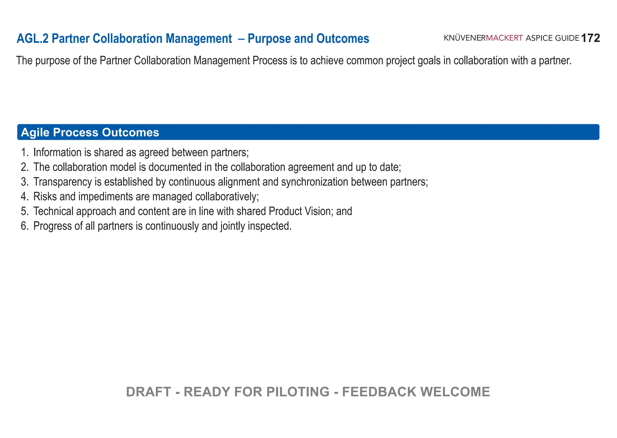
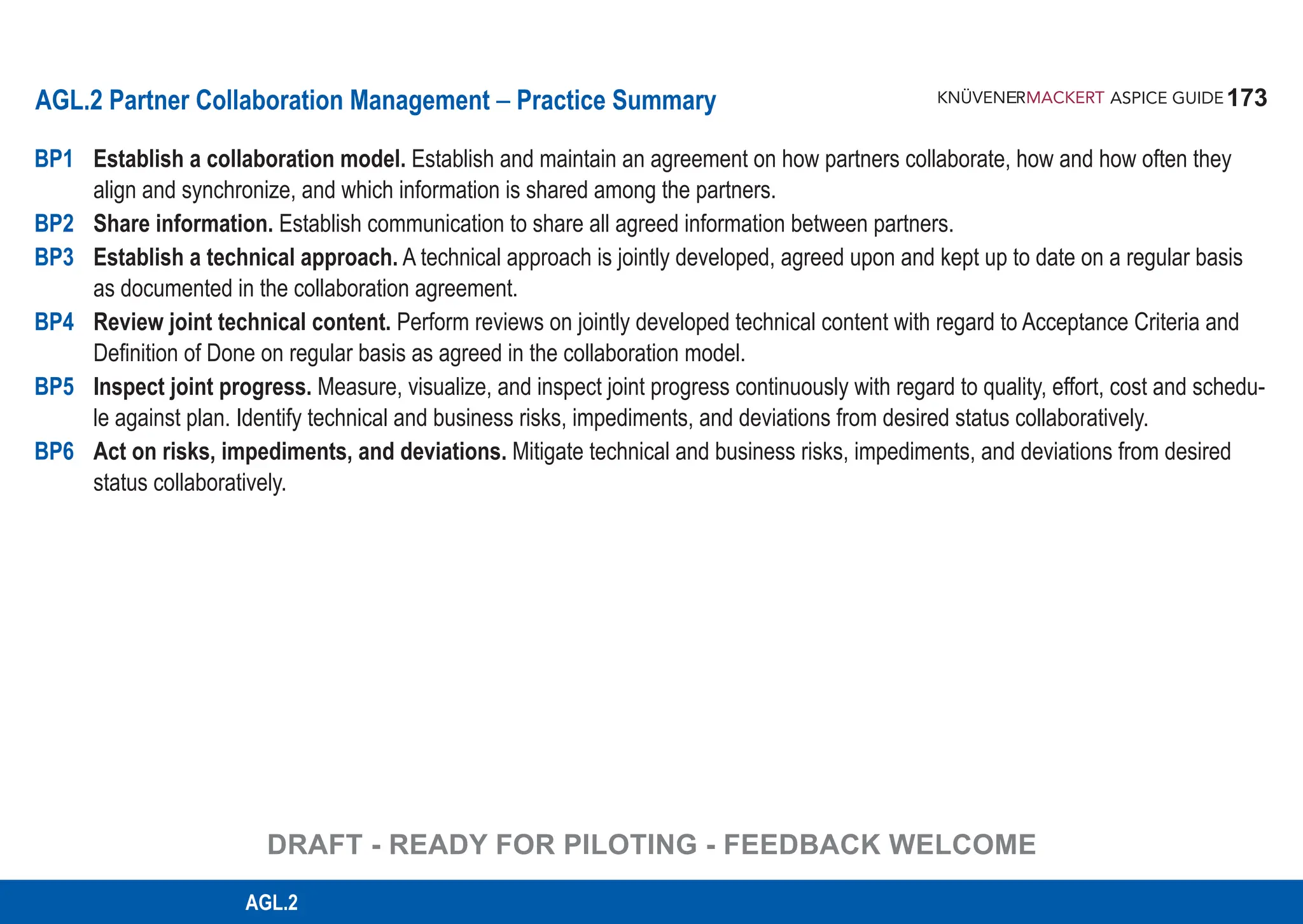
![174
ASPICE GUIDE
AGL.2 with 6 Base Practices
Establish a collaboration model. Establish and maintain an agreement on how partners collaborate, how and how often they
align and synchronize, and which information is shared among the partners. [OUTCOME 1, 2, 3]
Notes & Definitions:
▪ Ensure that the collaboration model is based on a common understanding regarding roles, meetings, and artifacts.
▪ While cooperation is a loosely coupled group work, agile collaboration is characterized by a teamwork with a common
goal, continuous alignment and synchronization.
▪ A Collaboration Agreement typically includes e.g., communication mechanisms with escalation paths and urgent
problem resolution, meeting structure, technical and organizational interfaces, infrastructure, roles including skills
and responsibility split, and ownership of artifacts.
Agile Work Products: Collaboration agreement, Product vision, Definition of Done
Supporting Agile Principles 4, 6, 11
BP1
174
DRAFT - READY FOR PILOTING - FEEDBACK WELCOME](https://image.slidesharecdn.com/aspice-guide-km2021-04-240204182441-58722c47/75/ASPICE-Guide-KM2021-04-pdf-174-2048.jpg)
![175
ASPICE GUIDE
Base practices
Share information. Establish communication to share all agreed information between partners.
[OUTCOME 1, 2, 3]
Notes & Definitions:
▪ In agile context, a suitable meeting structure may encompass Queue Replenishment, Product Backlog Refinement,
Iteration Planning, Stand up, Iteration Review, Retrospective. These collaborative activities highly depend on self
organization of the team (of teams).
▪ Information to be shared may include technical content, acceptance criteria, status, risks, impediments, and open points.
▪ Collaboration in an agile environment requires a common Definition of Ready and Definition of Done. It is up to the team
(of teams) to complement the agreed minimum set by own criteria.
Agile Work Products: Collaboration agreement, Product vision, Product roadmap, Product backlog, Open item list, Risk list,
Definition of Ready, Definition of Done, Impediment backlog
Supporting Agile Principles 4, 6, 8, 12
BP2
175
AGL.2
DRAFT - READY FOR PILOTING - FEEDBACK WELCOME](https://image.slidesharecdn.com/aspice-guide-km2021-04-240204182441-58722c47/75/ASPICE-Guide-KM2021-04-pdf-175-2048.jpg)
![176
ASPICE GUIDE
Base practices
Establish a technical approach. A technical approach is jointly developed, agreed
upon and kept up to date on a regular basis as documented in the collaboration agreement. [OUTCOME 1, 3, 4, 5]
Notes & Definitions:
▪ Constraints , risks , assumptions , and open items are , considered.
▪ The technical approach is aligned with the agile work approach (see AGL.1).
Agile Work Products: Product vision, Product backlog, Impediment backlog, Definition of Done / Definition of Ready,
Review record, Open item list, Risk list
Supporting Agile Principles 2, 4, 5, 6, 9, 10, 11, 12
BP3
176
DRAFT - READY FOR PILOTING - FEEDBACK WELCOME](https://image.slidesharecdn.com/aspice-guide-km2021-04-240204182441-58722c47/75/ASPICE-Guide-KM2021-04-pdf-176-2048.jpg)
![177
ASPICE GUIDE
Base practices
Review joint technical content. Perform reviews on jointly developed technical content with regard to Acceptance Criteria and
Definition of Done on regular basis as agreed in the Collaboration Agreement. [OUTCOME 1, 2, 3, 5]
Notes & Definitions:
▪ If rework is required, prioritize, plan and track work packages to closure. Ensure that the joint technical content is in line
with shared Product Vision.
▪ Acceptance Criteria are applicable to individual work packages.
▪ Definition of Done is to be considered for the work packages of the same type.
Agile Work Products: Product vision, Product roadmap, Product backlog, Iteration backlog, Definition of Done,
Review record, Open item list
Supporting Agile Principles 1, 2, 3, 4, 6, 7, 9, 10, 11, 12
BP4
177
AGL.2
DRAFT - READY FOR PILOTING - FEEDBACK WELCOME](https://image.slidesharecdn.com/aspice-guide-km2021-04-240204182441-58722c47/75/ASPICE-Guide-KM2021-04-pdf-177-2048.jpg)
![178
ASPICE GUIDE
Base practices
Inspect joint progress. Measure, visualize, and inspect joint progress continuously with regard to quality,
effort, cost and schedule against plan. Identify technical and business risks, impediments, and deviations from desired status
collaboratively. [OUTCOME 1, 3, 4, 6]
Notes & Definitions:
▪ Quality, effort, cost, and schedule can be monitored by metrics and KPIs agreed by the partners.
▪ Inspect is the ability of a team (of teams) to detect deviations from desired status.
Agile Work Products: Iteration/release burndown chart or cumulative flow diagram, Velocity chart, Open item list,
Risk list, Impediment backlog
Supporting Agile Principles 4, 5, 6, 7, 8, 12
BP5
178
DRAFT - READY FOR PILOTING - FEEDBACK WELCOME](https://image.slidesharecdn.com/aspice-guide-km2021-04-240204182441-58722c47/75/ASPICE-Guide-KM2021-04-pdf-178-2048.jpg)
![179
ASPICE GUIDE
Base practices
Act on risks, impediments, and deviations. Mitigate technical and business risks, impediments, and deviations from desired
status collaboratively. [OUTCOME 1, 4]
Notes & Definitions:
▪ Prioritize, plan and track open points to closure. In case of deviations from the desired status, jointly identify root causes,
introduce countermeasures and prevent reoccurrence.
▪ Adaption is the ability of a team (of teams) to timely adjust to an everchanging environment.
Agile Work Products: Collaboration agreement, Product vision, Product roadmap, Product backlog, Definition of Done,
Open item list, Risk list, Impediment backlog
Supporting Agile Principles 1, 2, 3, 4, 5, 9, 10, 11
BP6
179
AGL.2
DRAFT - READY FOR PILOTING - FEEDBACK WELCOME](https://image.slidesharecdn.com/aspice-guide-km2021-04-240204182441-58722c47/75/ASPICE-Guide-KM2021-04-pdf-179-2048.jpg)
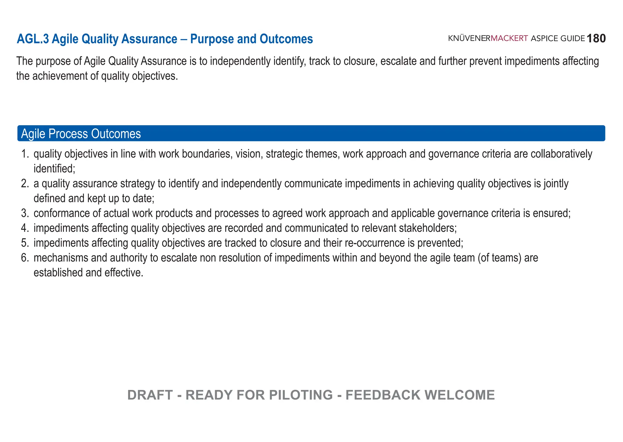
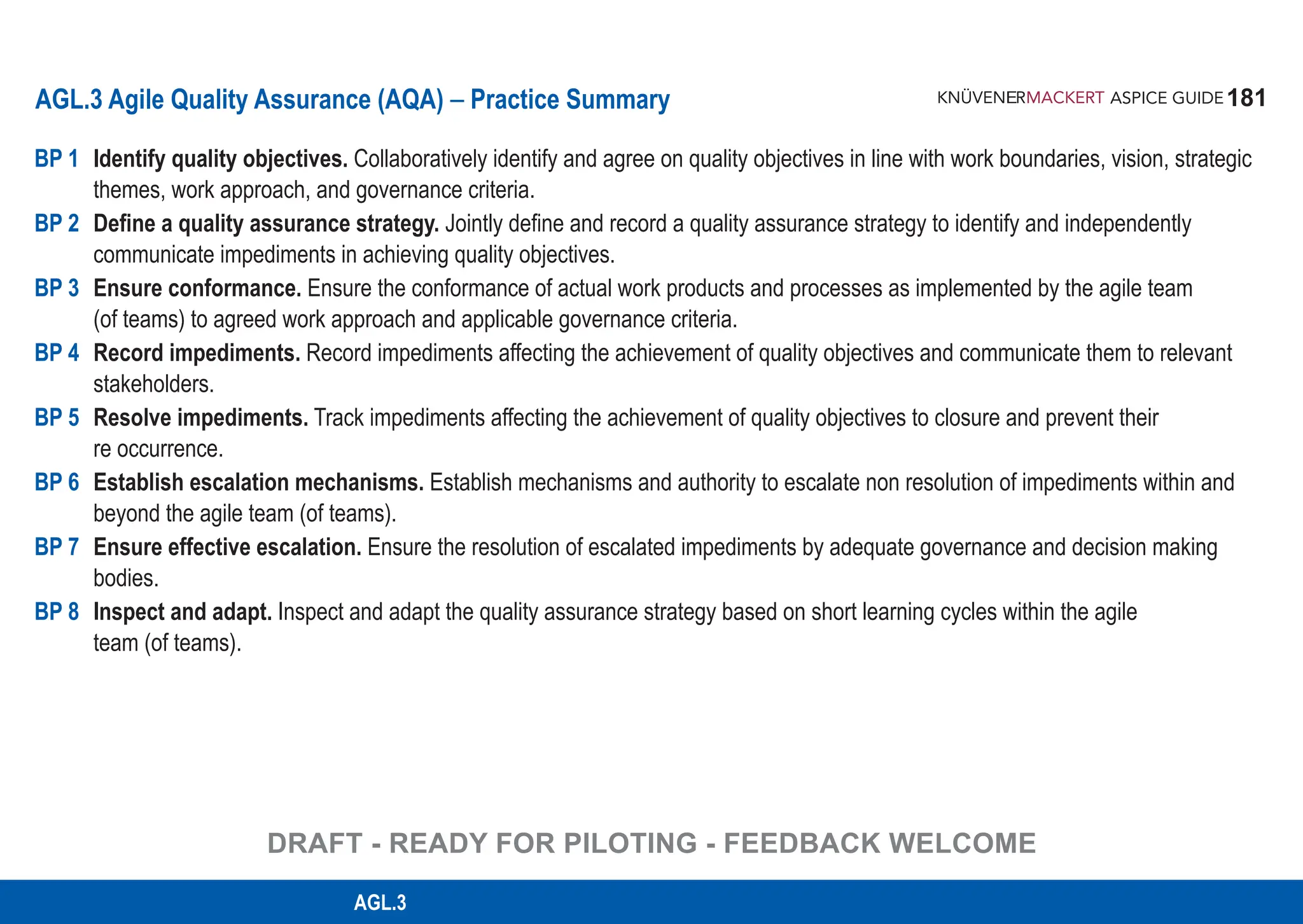
![182
ASPICE GUIDE
AGL.3 with 8 Base Practices
Identify quality objectives. Collaboratively identify and agree on quality objectives in line with work boundaries, vision,
strategic themes, work approach and governance criteria. [OUTCOME 1]
Notes & Definitions:
▪ Quality objectives
- encompass the work approach selected by the agile team (of teams) as well as the relevant governance processes
of the organization,
- are agreed collaboratively,
- are achieved by the agile team (of teams) across the iterations.
▪ Quality objectives lead to the establishment of suitable work processes and quality characteristics for the work products.
▪ Among other, criteria for contents definition, structure, review, approval of work products as well as any other criterion
derived from standards are part of the quality objectives.
Agile Work Products: Quality objectives
Supporting Agile Principles 1, 3, 4
BP1
182
DRAFT - READY FOR PILOTING - FEEDBACK WELCOME](https://image.slidesharecdn.com/aspice-guide-km2021-04-240204182441-58722c47/75/ASPICE-Guide-KM2021-04-pdf-182-2048.jpg)
![183
ASPICE GUIDE
AGL.3 with 8 Base Practices
Define a quality assurance strategy. Jointly define and record a quality assurance strategy to identify and independently
communicate impediments in achieving quality objectives. [OUTCOME 2]
Notes & Definitions:
▪ The agile team (of teams) is jointly responsible for the quality of their processes and work products.
▪ The strategy encompasses the quality of work processes and developed products.
▪ The strategy includes the quality assurance of supplier deliverables.
▪ The strategy addresses methods to identify, track to closure, escalate and further prevent impediments affecting the
achievement of quality objectives.
▪ The strategy includes the communication of impediments independently from the development team.
▪ Agile quality assurance may make use of the results of other processes such as e g iteration reviews and retrospectives,
problem analysis, reports.
▪ The strategy is agreed to, recorded and communicated.
Agile Work Products: Agile quality strategy, Quality plan
Supporting Agile Principles 2, 4, 6, 12
BP2
183
AGL.3
DRAFT - READY FOR PILOTING - FEEDBACK WELCOME](https://image.slidesharecdn.com/aspice-guide-km2021-04-240204182441-58722c47/75/ASPICE-Guide-KM2021-04-pdf-183-2048.jpg)
![184
ASPICE GUIDE
AGL.3 with 8 Base Practices
Ensure conformance. Ensure the conformance of actual work products and processes as implemented by the agile team
(of teams) to agreed work approach and applicable governance criteria. [OUTCOME 2, 3]
Notes & Definitions:
▪ Typically, criteria for the quality of processes and work product are defined, e g in a DoR and DoD.
▪ Quality assurance activities are planned, e g as part of the backlog and iteration planning.
▪ Quality assurance checks objectively for each release that work products and processes are aligned with the
work approach and the applicable governance criteria.
▪ The agile methodology followed by the agile team (of teams) is also verified.
Agile Work Products: Review record
Supporting Agile Principles 1, 3, 5
BP3
184
DRAFT - READY FOR PILOTING - FEEDBACK WELCOME](https://image.slidesharecdn.com/aspice-guide-km2021-04-240204182441-58722c47/75/ASPICE-Guide-KM2021-04-pdf-184-2048.jpg)
![185
ASPICE GUIDE
AGL.3 with 8 Base Practices
Record impediments. Ensure the conformance of actual work products and processes as implemented by the agile team
(of teams) to agreed work approach and applicable governance criteria. [OUTCOME 4]
Notes & Definitions:
▪ Record impediments that affect the achievement of quality objectives.
▪ Communicate regularly with the team (of teams) regarding impediments and desired performance. This can happen at
various levels, during daily stand ups, during iteration reviews and retrospectives, etc.
▪ The agile team (of teams) plans in the backlog the corrective actions necessary to resolve the recorded impediments.
▪ Communication can include metrics, risks, qualitative feedback, etc.
▪ Metrics relevant to process and product quality can be present. This can include(but not limited to) velocity forecasts,
defect trends, increments released per gate, etc.
▪ Communication should be based on the perspective relevant for the recipient agile team (of teams), management,
customer.
Agile Work Products: Impediment backlog, Backlog, Communication record
Supporting Agile Principles 6, 7, 12
BP4
185
AGL.3
DRAFT - READY FOR PILOTING - FEEDBACK WELCOME](https://image.slidesharecdn.com/aspice-guide-km2021-04-240204182441-58722c47/75/ASPICE-Guide-KM2021-04-pdf-185-2048.jpg)
![186
ASPICE GUIDE
AGL.3 with 8 Base Practices
Resolve impediments Track. Track impediments affecting the achievement of quality objectives to closure and prevent their
re-occurrence. [OUTCOME 5]
Notes & Definitions:
▪ Ensure that impediments are correctly understood by relevant stakeholders.
▪ Ensure that resolving and closing of impediments are planned by the agile team(of teams).
▪ Track and verify the closure of impediments.
▪ Analyse and communicate root causes of re-occurring impediments.
▪ Support the agile team (of teams) to avoid impediment re occurrence.
Agile Work Products: Impediment backlog, Backlog, Communication record
Supporting Agile Principles 6, 8, 12
BP5
186
DRAFT - READY FOR PILOTING - FEEDBACK WELCOME](https://image.slidesharecdn.com/aspice-guide-km2021-04-240204182441-58722c47/75/ASPICE-Guide-KM2021-04-pdf-186-2048.jpg)
![187
ASPICE GUIDE
AGL.3 with 8 Base Practices
Establish escalation mechanisms. Establish mechanisms and authority to escalate non resolution of impediments within
and beyond the agile team(of teams). [OUTCOME 6]
Notes & Definitions:
▪ The escalation path is known by each team member and those that contribute to the team.
▪ The escalation path begins with the team as the starting point Typically, the path ends with the highest authority
in the organisation.
▪ The escalation path is typically recorded e g by an organigram.
▪ The escalation path is accessible to anyone in the organisation.
▪ The impediment backlog is visible at least to anyone in the escalation path and the team (of teams).
Agile Work Products: Escalation path, Communication record, Impediment backlog
Supporting Agile Principles 1, 3, 4, 7, 8, (9)
BP6
187
AGL.3
DRAFT - READY FOR PILOTING - FEEDBACK WELCOME](https://image.slidesharecdn.com/aspice-guide-km2021-04-240204182441-58722c47/75/ASPICE-Guide-KM2021-04-pdf-187-2048.jpg)
![188
ASPICE GUIDE
AGL.3 with 8 Base Practices
Ensure effective escalation. Ensure the resolution of escalated impediments by adequate governance and decision-making
bodies. [OUTCOME 6]
Notes & Definitions:
▪ Primarily, the agile team (of teams) is jointly responsible for resolving impediments and collaborates closely with the
person who tracks their impediments to closure
▪ Each member in the escalation path maintains seamless communication to its lower and its upper partners in the path
▪ The agile quality assurance responsible acts as ‘escalation guard’ and is empowered to involve higher authorities of the
escalation path, if necessary
▪ Any escalation rationale, decision, action and effect is recorded in the impediment backlog
Agile Work Products: Escalation record, Communication record, Impediment backlog
Supporting Agile Principles 1, 3, 4, 7, 8, (9)
BP7
188
DRAFT - READY FOR PILOTING - FEEDBACK WELCOME](https://image.slidesharecdn.com/aspice-guide-km2021-04-240204182441-58722c47/75/ASPICE-Guide-KM2021-04-pdf-188-2048.jpg)
![189
ASPICE GUIDE
AGL.3 with 8 Base Practicesapt
Inspect and adapt. Inspect and adapt the quality assurance strategy based on short learning cycles within the agile team
(of teams). [OUTCOME 1, 2]
Notes & Definitions:
▪ The quality strategy typically considers different organizational levels of development
▪ Inspect and adapt events take place regularly in a collaborative way with the agile team (of teams) and relevant
stakeholders
▪ The learning aspects consider multiple views, including management, teams and customer
▪ The adaptations of quality strategy and/or objectives are consistent with the organisation strategy and reflect customer
quality needs
▪ The adaptations and learnings are reflected and made visible, e g in retrospectives by maintaining DoD and DoR criteria
Agile Work Products: Quality plan, Agile quality strategy, Quality objectives, Meeting records
Supporting Agile Principles 4, 8, 12
BP8
189
AGL.3
DRAFT - READY FOR PILOTING - FEEDBACK WELCOME](https://image.slidesharecdn.com/aspice-guide-km2021-04-240204182441-58722c47/75/ASPICE-Guide-KM2021-04-pdf-189-2048.jpg)
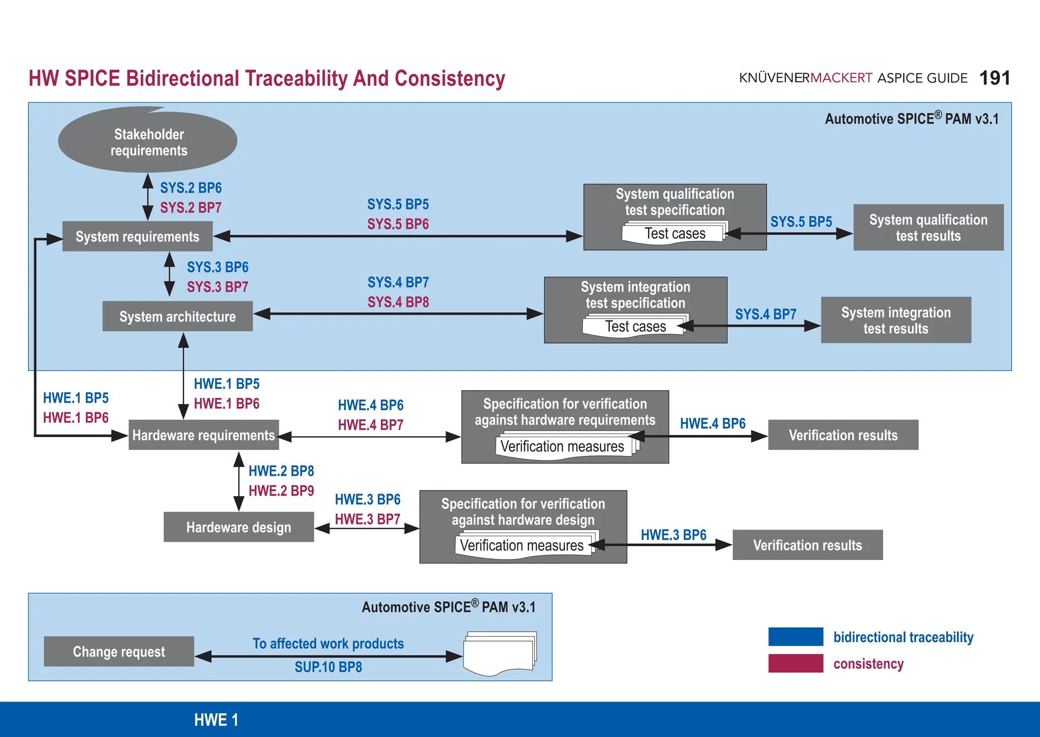
![192
ASPICE GUIDE
13-04 Communication record [OUTCOME 8] 15-01 Analysis report [OUTCOME 2, 3, 4, 7]
13-19 Review record [OUTCOME 6] 17-08 Interface requirements specification [OUTCOME 1, 3]
13-21 Change control record [OUTCOME 5, 7] 17-HW01 Hardware requirements specification [OUTCOME 1]
13-22 Traceability record [OUTCOME 1, 6]
HWE.1 Hardware Requirements Analysis
The purpose of the Hardware Requirements Analysis process is to transform the hardware-related system requirements or stakeholder
requirements, and hardware-related system architectural design, into a set of hardware requirements.
Process outcomes – as a result of successful implementation of this process
1. The hardware requirements to be allocated to the hardware elements of the system and their interfaces are defined.
2. Hardware requirements are categorized and analysed.
3. The impact of hardware requirements on the operating environment is analysed.
4. Prioritization of hardware requirements is defined.
5. The hardware requirements are updated as needed.
6. Consistency and bidirectional traceability are established between system requirements and hardware requirements. Consistency
and bidirectional traceability are established between system architectural design and hardware requirements.
7. The hardware requirements are evaluated for cost, schedule and
8. The hardware requirements are agreed and communicated to all affected parties.
Output work products](https://image.slidesharecdn.com/aspice-guide-km2021-04-240204182441-58722c47/75/ASPICE-Guide-KM2021-04-pdf-192-2048.jpg)
![193
ASPICE GUIDE
HWE.1 with 7 Base practices
Specify hardware requirements. Use the stakeholder and system requirements, and the system architecture including interface
definitions, as well as changes to these, to identify the required functions and capabilities of the hardware. Specify hardware
requirements including hardware interface requirements in a hardware requirements specification according to state-ofthe- art
characteristics for requirements. [OUTCOME 1,5]
[ISO 26262-5:2018, clauses 6.4.1, 6.4.2, 6.4.5]
A single requirement usually needs both ‘functional’ and ‘nonfunctional’ information in it, acc. to the definition of this terms
in ISO IEC IEEE 29148 [25] or IREB CPRE [26]. For further information see Rationale 5 – No Usage of Terms Functional
and Non-functional Requirement.
Characteristics of requirements are defined in standards such as ISO IEEE 29148 clause 5.2, or ISO 26262-8:2018
clause 6.4.2.4. According to these standards characteristics of an individual requirement include being: Typical analysis
criteria are: resource requirements, scheduling issues, risks, benefits, etc. Change request activities ensure that change
requests are systematically identified, described, recorded, analyzed, implemented, and managed. The change request
management strategy may cover different proceedings across the product life cycle, e.g. during prototype construction
and series development.
• verifiable
• design-free/implementation-free (see Section 3.6 here)
• unambiguous
• comprehensible
• consistent in itself
• complete in itself
• not contradicting any other requirement
• atomic/singular
• defined through language criteria and sentence structure supporting the above characteristics
BP 1
2
193
HWE 1
1](https://image.slidesharecdn.com/aspice-guide-km2021-04-240204182441-58722c47/75/ASPICE-Guide-KM2021-04-pdf-193-2048.jpg)
![194
ASPICE GUIDE
HWE.1 with 7 Base practices
In case of hardware development only, the system requirements and the system architecture refer to a given operating
environment (see also Note 14). In that case, stakeholder requirements should be used as the basis for identifying the
required functions and capabilities of the hardware.
Hardware requirements specify particular desired characteristics of the hardware and can include
• lifetime and mission profile, lifetime robustness (as, in contrast to software, hardware characteristics
are impacted by physical influences which may change the hardware’s characteristics over time)
• maximum price
• storage and transportation requirements
• functional behaviour of analog or digital circuits and logic
• quiescent current, voltage impulse responsiveness to crank, start-stop, drop-out, load dump
• temperature, maximum hardware heat dissipation
• power consumption depending on the operating state such as sleepmode, start-up, reset conditions
• frequencies, modulation, signal delays, filters, control loops
• power-up and power-down sequences, accuracy and precision of signal acquisition or signal processing time
• computing resources such as memory space and CPU clock tolerances
• maximum abrasive wear and shearing forces for e.g. pins or soldering joints
• requirements resulting from lessons learned [ISO 26262-2:2018, clause 5.4.2.6]
• safety related requirements derived from the technical safety concept [ISO 26262-5:2018, clauses 6.4.1, 6.4.2]
BP 1
3
4
194](https://image.slidesharecdn.com/aspice-guide-km2021-04-240204182441-58722c47/75/ASPICE-Guide-KM2021-04-pdf-194-2048.jpg)
![195
ASPICE GUIDE
HWE 1
HWE.1 with 7 Base practices
Some numerical values, to be mentioned in complete requirements statements, may only be determined in an
evolutionary way by means of e.g. measurements, prototype testing. Incomplete or underspecified aspects should be
considered as a risk in HWE.1.BP3
EXAMPLE: Radio connection at system level Sender and receiver, 400m away from each other. Both components
will require a max. signal-to-noise ratio. However, these values can only be determined in an empirical way. Therefore,
exact hardware requirements cannot be defined in the first place.
Hardware requirements are often integrated in superordinate requirements specifications, or spread across several
work products, such as customer requirements, system requirements, and industry standards.
Reasons for an update may be e.g.
• change requests,
• results of safety analyses [ISO 26262-9, clauses 8.4.3 and 8.4.4] and analysis of dependent failures
[ISO 26262-9 clause 7.4]
BP 1
5
6
7
195](https://image.slidesharecdn.com/aspice-guide-km2021-04-240204182441-58722c47/75/ASPICE-Guide-KM2021-04-pdf-195-2048.jpg)
![196
ASPICE GUIDE
Structure hardware requirements. Structure the hardware requirements in the hardware requirements specification
[OUTCOME 2, 4, 8]
In regards to classifying requirements into ‘funcional’ and ‘nonfunctional’, acc. to the definition of this terms in ISO IEC
IEEE 29148 [25] or IREB CPRE [26], see Rationale 5 – No Usage of Terms Functional and Nonfunctional Requirement.
Structuring supports the comprehensibility and the managing of requirements, and can be done by e.g.
• grouping according to HW functionalities
• grouping according to hardware components, e.g. the hardware requirements are restructured depending on the
allocation in the hardware architecture
• categorising based on relevant criteria for the project such as organisational, technical, legal, and internal topics.
• categorizing according to planned variants of the product.
• labelling with ASIL attribute [ISO 26262-8:2018, clause 6.4.2.5c)]
• sorting in a logical order for the project
• prioritizing according to stakeholder needs
• prioritizing through the assignment of hardware content to planned samples or series releases.
Refer to Automotive SPICE® SPL.2.BP1.
Analyse hardware requirements. Analyse the specified hardware requirements including their interdependencies to ensure
correctness, technical feasibility, and to support risk identification. Determine the impact on cost, schedule, and the technical
impact. [OUTCOME 2, 7]
The analysis of impact on cost and schedule supports the adjustment of project estimates. Refer to Automotive SPICE®
MAN.3.BP5 and MAN.3.BP8. For risk identification refer to Automotive SPICE® MAN.5.BP3.
HWE.1 with 7 Base practices
BP 2
BP 3
196
8
9
10](https://image.slidesharecdn.com/aspice-guide-km2021-04-240204182441-58722c47/75/ASPICE-Guide-KM2021-04-pdf-196-2048.jpg)
![197
ASPICE GUIDE
HWE.1 with 7 Base practices
Analyse the impact on the operating environment. Analyse the impact that the hardware requirements will have on
interfaces of the system elements and the operating environment. [OUTCOME 3, 7]
Aspects of the operation environment may be e.g.
• the mounting space and position
• temperature
• humidity
• mechanical stress
• EMC/EMI, or ESD
Interfaces to the system elements may be e.g.
• connector
• cable harness
• optical/illumination
• voltage/currents
• power supply
• heat dissipation
The system level (e.g. SYS.3 in Automotive SPICE®) is responsible for deciding on the connection technology of the interfaces
of system elements (crimping, soldering, pressing, etc.).
BP 4
12
197
HWE 1
11](https://image.slidesharecdn.com/aspice-guide-km2021-04-240204182441-58722c47/75/ASPICE-Guide-KM2021-04-pdf-197-2048.jpg)
![198
ASPICE GUIDE
Establish bidirectional traceability. Establish bidirectional traceability between a single hardware requirement and
system requirements. Establish bidirectional traceability between a single hardware requirement and the system architecture.
[OUTCOME 6]
For a particular hardware requirement traceability redundancy should be avoided by establishing a combination of these
approaches that covers the project and the organisational needs.
Bidirectional traceability supports coverage, consistency, and impact analysis.
Ensure consistency. Ensure consistency between system requirements and hardware requirements. Ensure consistency
between the system architecture and hardware requirements. [OUTCOME 6] [ISO 26262-5:2018, clause 6.4.9]
Consistency is supported by bidirectional traceability and can be demonstrated by review records.
In case of hardware development only, the system requirements and system architecture refer to a given operating en-
vironment (see also note 13). In that case, consistency and bidirectional traceability have to be ensured between stakehol-
der requirements and hardware requirements.
Safety related requirements shall be compliant with system architectural constraints such as
• Fault tolerant time interval [ISO 26262-5:2018, clause 6.4.7]
• Fault handling time interval [ISO 26262-5:2018, clause 6.4.7]
• Multiple-point fault detection interval [ISO 26262-5:2018, clause 6.4.8]
Communicate agreed hardware requirements. Communicate the agreed hardware requirements and updates to
hardware requirements to all relevant parties. [OUTCOME 8]
HWE.1 with 7 Base practices
BP 5
14
BP 7
13
15
16
17
198
BP 6](https://image.slidesharecdn.com/aspice-guide-km2021-04-240204182441-58722c47/75/ASPICE-Guide-KM2021-04-pdf-198-2048.jpg)
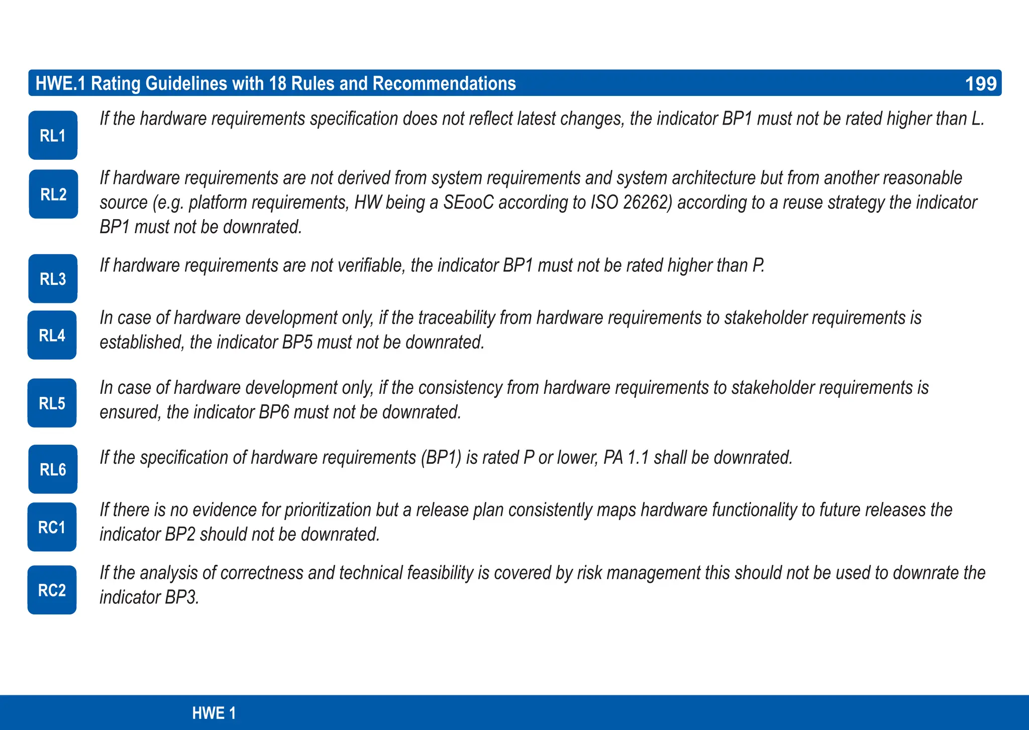
![200
ASPICE GUIDE
HWE.1 Rating Guidelines with 18 Rules and Recommendations
[HWE.1.RC.3] If the analysis of hardware requirements impact on cost and schedule is covered by the estimation of work
packages in the project planning this should not be used to downrate the indicator BP3.
[HWE.1.RC.4] If PA 1.1 for SYS.2 is downrated, this should be in line with the rating of the indicator BP1.
[HWE.1.RC.5] If PA 1.1 for SYS.3 is downrated, this should be in line with the rating of the indicator BP1.
[HWE.1.RC.6] If the indicator BP3 is downrated, this should be in line with the rating of the indicators ‘determine, monitor
and adjust project estimates and resources’ (Automotive SPICE® MAN.3.BP5) and ‘determine, monitor and adjust project
schedule (Automotive SPICE® MAN.3.BP8)’.
[HWE.1.RC.7] If the indicator BP3 is downrated, this should be in line with the rating of the indicator ‘evaluate feasibility
of the project’ (Automotive SPICE® MAN.5.BP3).
[HWE.1.RC.8] If Automotive SPICE® SYS.2 BP1 is downrated, this should be in line with the rating of the indicator BP5.
[HWE.1.RC.9] If Automotive SPICE® SYS.3 BP1 is downrated, this should be in line with the rating of the indicator BP5.
[HWE.1.RC.10] If Automotive SPICE® SYS.2 BP1 is downrated, this should be in line with the rating of the indicator BP6.
[HWE.1.RC.11] If Automotive SPICE® SYS.3 BP1 is downrated, this should be in line with the rating of the indicator BP6.
RC3
RC4
RC5
RC6
RC7
RC8
RC9
RC10
RC11
200](https://image.slidesharecdn.com/aspice-guide-km2021-04-240204182441-58722c47/75/ASPICE-Guide-KM2021-04-pdf-200-2048.jpg)

![202
ASPICE GUIDE
04-HW01 Hardware architecture [OUTCOME 1, 2, 3, 4] 11-HW02 Special characteristics [OUTCOME 9]
04-HW02 Hardware detailed design description [OUTCOME 1, 3, 4, 5] 13-04 Communication record [OUTCOME 7, 8, 9, 10]
04-HW03 Schematics [OUTCOME1, 3] 13-19 Review record [OUTCOME 6]
04-HW04 Bill of materials [OUTCOME 1] 13-22 Traceability record [OUTCOME 6]
04-HW05 Layout [OUTCOME 1] 15-01 Analysis report [OUTCOME 5]
11-HW01 Hardware production data [OUTCOME 7, 8] 17-08 Interface requirement specification [OUTCOME 3]
HWE.2 Hardware Design
The purpose of the Hardware Design process is to provide an evaluated design, that is suitable for manufacturing, and to derive
production-relevant data.
Process outcomes – as a result of successful implementation of this process
1. A HW architecture and HW detailed design is developed.
2. The HW requirements are allocated to the hardware components or their interfaces.
3. The interfaces between the HW elements are defined.
4. The dynamic behaviour of the HW elements is defined.
5. The HW architecture and the HW detailed design are evaluated.
6. Consistency and bidirectional traceability are established between hardware requirements and hardware components.
7. Hardware production data is derived from the HW detailed design and communicated to the affected parties.
8. Information for production test is derived from the HW detailed design and communicated to the affected parties.
Output work products](https://image.slidesharecdn.com/aspice-guide-km2021-04-240204182441-58722c47/75/ASPICE-Guide-KM2021-04-pdf-202-2048.jpg)
![203
ASPICE GUIDE
Develop hardware architecture. Develop the hardware architecture that identifies the hardware components. Describe the
rationale for the defined hardware architecture. [OUTCOME 1]
Hardware design typically starts at an abstract level, using e.g. recursively decomposed block diagrams that identify the
HW components.
One purpose of a hardware architectural design is to provide motivation, reasoning, and explanatory context information to
other subject matter experts in the hardware domain and product domain, respectively.
The appropriate level of architectural detail is driven by e.g.
• the need for integration of reused hardware components
• the complexity of the hardware components
• the allocation of requirements to hardware components
• the intent for future reuse of hardware components
• the intent for adaptability of hardware components
The hardware architecture may include a ground concept, supply concept, EMC concept.
Hardware elements might inherit the highest ASIL of corresponding requirements, unless the criteria for coexistence in
accordance with ISO 26262- 9:2018, clause 6 are met. [ISO 26262-5:2018 clause 7.4.1.4]
HWE.2 with 9 Base practices
BP 1
1
203
2
3
4
5
HWE 2](https://image.slidesharecdn.com/aspice-guide-km2021-04-240204182441-58722c47/75/ASPICE-Guide-KM2021-04-pdf-203-2048.jpg)
![204
ASPICE GUIDE
Develop hardware detailed design. Develop a hardware detailed design based on components of the hardware architecture.
Identify all hardware parts based on the related requirements. Describe the detailed design for intended hardware variants.
[OUTCOME 1]
A HW detailed design typically comprises schematics, RTL design, PCB characteristics, layouts, bill of materials (BOM),
and a sufficiently comprehensive description.
The identification of hardware parts and their suppliers may be subject to a pre-defined repository. For supplier
selection see ACQ.2 in ISO/IEC 33060; see also IATF 16949:2016, clause 8.4.1.2.
Hardware design may be subject to constraints such as
• availability of hardware parts on the market
• hardware design rules, layout rules
• creepage and clearance distances
• compliance of HW parts with industry standards such as AEC-Q, REACH
Hardware elements might inherit the highest ASIL of corresponding requirements, unless the criteria for coexistence in
accordance with ISO26262- 9:2018, clause 6 are met. [ISO 26262-5:2018 clause 7.4.1.4]
In the case of safety-related development, the hardware detailed design should consider the results of safety analyses
[ISO 26262-9:2018, clauses 8.4.3 and 8.4.4] and analysis of dependent failures. [ISO 26262-9:2018 clause 7.4.2]
HWE.2 with 9 Base practices
BP 2
6
204
7
8
9
10](https://image.slidesharecdn.com/aspice-guide-km2021-04-240204182441-58722c47/75/ASPICE-Guide-KM2021-04-pdf-204-2048.jpg)
![205
ASPICE GUIDE
Define interfaces of the hardware elements. Specify and document the interfaces between the hardware elements.
[OUTCOME 1, 2, 3]
A hardware element interface is typically defined by output, input, type, and electrical characteristics including signal
tolerances.
Examples of interfaces are
• high level interfaces like SPI, I2C, CAN, LIN, Ethernet
• electrical interconnections
• thermal interfaces between hardware parts (heat dissipation)
Describe dynamic behaviour. Evaluate and document the dynamic behaviour of the relevant hardware elements and
the interaction between them. [OUTCOME 1, 4]
Examples are
• transitions between electrical states of hardware parts
• power-up and power-down sequences
• frequencies, modulations
• signal delays
• debounce times
• filters
• short circuit behaviour
• self-protection
Not all hardware elements have dynamic behaviour that needs to be described.
Particular views of the architecture may require a description of the dynamic behaviour of the complete hardware.
HWE.2 with 9 Base practices
BP 3
11
205
12
BP 4
13
14
15
HWE 2](https://image.slidesharecdn.com/aspice-guide-km2021-04-240204182441-58722c47/75/ASPICE-Guide-KM2021-04-pdf-205-2048.jpg)
![206
ASPICE GUIDE
Allocate hardware requirements. Allocate the hardware requirements to the hardware elements and interfaces of the
hardware architecture.[OUTCOME 2] [ISO 26262-5:2018 clauses 6.4.1, 7.4.1.2]
This allocation typically reflects one direction of bidirectional traceability addressed by HWE.2.BP8.
Allocation might be done based on single requirements or cluster of requirements.
Allocation should be on appropriate level of granularity, at least to single hardware components.
Evaluate the hardware architecture and the hardware detailed design. Analyse and evaluate the hardware architecture
and detailed design against defined quantitative or qualitative criteria, including risks, manufacturability, and verifiability. Identify
special characteristics. [OUTCOME 5, 9] [ISO 26262-5:2018 clause 10.4.3, clause 7.4.5 and clause 9.4.1.2 NOTE 2]
Examples for risk evaluation are
• prototype testing
• simulations
• calculations such as ‘Weibull distribution’, WCCA
• qualitative or quantitative analyses such as FMEA, FMEDA/FMECA, ETA, FTA, DFA
• identification of interference such as temperature, vibrations, water, dust, EMI, noise factor, crosstalk
[ISO 26262-5:2018 clause 7.4.1.7]
Example for manufacturability are
• evidence for conformity with production constraints
• evidence of availability for all hardware parts
• appropriate knowledge of production technology and their availability
The results of the evaluation can be used as input for the verification of the physical hardware against the
hardware design (HWE.3).
HWE.2 with 9 Base practices
BP 5
16
206
17
BP 6
19
20
18
21](https://image.slidesharecdn.com/aspice-guide-km2021-04-240204182441-58722c47/75/ASPICE-Guide-KM2021-04-pdf-206-2048.jpg)
![207
ASPICE GUIDE
HWE.2 with 9 Base practices
BP 6
207
In case of safety-related development hardware design evaluation might include checking the criteria for coexistence of
elements as explained in ISO 26262- 9:2018 clauses 6.4.2, 6.4.3, and 6.4.4.
In case of safety-related development, hardware design evaluation might also include safety analysis in order to
• identify faults, or failures, and their potential causes, that can lead to the
violation of a safety goal, or a safety requirement, respectively
• identify hardware-related hazards not yet considered in the hazard analysis
and risk assessment above the hardware level
[ISO 26262-5:2018 clauses 6.4.3, 6.4.4 and 6.4.8], [ISO 26262-9:2018 clauses 8.1 and 8.4.5]
In case of safety-related development, hardware design evaluation might also include dependent failure analysis in
order to confirm that sufficient independence is achieved. [ISO 26262-9:2018, clauses 7.1 and 7.4]
In case of safety-related development, hardware design evaluation by means of quantitative safety analyses might
also include the consideration of ‘dedicated measures’ such as hardware part over-design (e.g. electrical or thermal
stress rating) or physical separation (e.g. spacing of contacts on a printed circuit board) [ISO 26262-5:2018 clauses 9.4.2]
Even in case of reuse of hardware elements, the suitability for the current application shall be evaluated.
Evaluation may also include the checking of application notes and erratas.
If an application review is performed with the suppliers of hardware parts (e.g. SBC) refer to SUP.4 or ACQ.4
in Automotive SPICE®.
In the semiconductor context, design evaluation typically includes pre-silicon verification, and may include subsequent
steps. Still, the purpose of such verification activities in the context of HWE.2 is to critically review the design specification
itself but not the physical product sample.
22
23
24
25
26
27
28
29
HWE 2](https://image.slidesharecdn.com/aspice-guide-km2021-04-240204182441-58722c47/75/ASPICE-Guide-KM2021-04-pdf-207-2048.jpg)
![208
ASPICE GUIDE
Establish bidirectional traceability. Establish bidirectional traceability between hardware elements. [OUTCOME 6]
[ISO 26262-5:2018 clause 7.4.1.5]
Bidirectional traceability supports coverage, consistency and impact analysis.
Traceability should be on appropriate level of granularity, at least to single hardware components.
Ensure consistency. Ensure consistency between hardware requirements and hardware components of the hardware
architecture. Ensure consistency between hardware components of the hardware architecture and the hardware parts of
the hardware detailed design. [OUTCOME 6]
Consistency is supported by bidirectional traceability and can be demonstrated by review records.
A typical solution that supports the consistency between hardware detailed design and hardware architecture is to draw
frames around those hardware parts in the schematic that represent a hardware component.
Ensure safety requirements are considered in hardware architecture. [ISO 26262-5:2018 clauses 7.4.1.1]
Communicate all information needed to relevant parties. Communicate the hardware architecture and hardware detailed
design and all updates of hardware architecture and hardware detailed design to all relevant parties. Provide relevant
production data and special characteristics to the affected parties. [OUTCOME 7, 8, 9, 10]
Interface definitions (e.g. the hardware software interface or interfaces to mechanical elements) might be impacted by
hardware architecture and hardware design adaptations. Refer to Automotive SPICE® SYS.3 and SUP.10, respectively.
[ISO 26262-5:2018 clause 6.4.10]
If hazards are identified by the hardware design not yet reflected in the hazard analysis and risk assessment, they need
to be communicated to all relevant parties. [ISO 26262-5:2018 clause 7.4.3.6]
BP 8
HWE.2 with 9 Base practices 208
BP 7
31
BP 9
32
33
34
30
35
36](https://image.slidesharecdn.com/aspice-guide-km2021-04-240204182441-58722c47/75/ASPICE-Guide-KM2021-04-pdf-208-2048.jpg)
![209
ASPICE GUIDE
HWE.2 Rating Guidelines with Rules and Recommendations
[HWE.2.RL.1] If manufacturability is not evaluated in the context of the indicator BP6, then PA 1.1 shall be downrated.
[HWE.2.RL.2] If the allocation of the hardware requirements to elements of the hardware architecture BP3 is downrated,
the indicator BP8 shall be downrated.
[HWE.2.RC.1] If HWE.1.PA.1.1 is downrated, this should be in-line with the rating of the indicator BP1.
RL1
RL2
RC1
209
HWE 2
Production data typically includes the bill of materials (BOM), GERBER data, placement data, mask data (GDS2), and
input to e.g. ICT, AOI, AXI, EOL, wafer- or package level test.
Information for EOL test might include loads to be used.
Production processes are not in the scope of this HWE PRM/PAM. See Rationale 1 – No Production Process
BP 9
HWE.2 with 9 Base practices 209
37
38
39](https://image.slidesharecdn.com/aspice-guide-km2021-04-240204182441-58722c47/75/ASPICE-Guide-KM2021-04-pdf-209-2048.jpg)
![210
ASPICE GUIDE
08-HW01 Verification plan [OUTCOME 1] 13-19 Review record [OUTCOME 6]
08-HW02 Verification specification [OUTCOME 3, 4] 13-22 Traceability record [OUTCOME 6]
13-01 Acceptance record [OUTCOME 2] 13-HW01 Verification result [OUTCOME 5, 7]
13-04 Communication record [OUTCOME 7]
HWE.3 Verification against Hardware Design
The purpose of the Verification against Hardware Design process is to ensure that the hardware is verified to provide evidence for
compliance with the hardware design.
Process outcomes – as a result of successful implementation of this process
1. A strategy for the verification against hardware design is defined, including a regression strategy consistent with the project plan
and release plan, as well as suitable measurement and verification equipment.
2. Hardware design-compliant samples are received according to the strategy for the verification against hardware design.
3. A verification specification is developed according to the strategy for the verification against hardware design that is suitable to
provide evidence for compliance with the hardware design.
4. Verification measures included in the specification are selected according to the verification strategy and the release plan.
5. Verification is performed using the selected verification measures, and verification results are recorded.
6. Consistency and bidirectional traceability are established between hardware elements and verification measures; bidirectional
traceability is established between verification measures and verification results.
7. Verification results are summarized and communicated to all affected parties.
Output work products](https://image.slidesharecdn.com/aspice-guide-km2021-04-240204182441-58722c47/75/ASPICE-Guide-KM2021-04-pdf-210-2048.jpg)
![211
ASPICE GUIDE
Develop a strategy for the verification against hardware design. Develop a strategy for the verification against hardware
design including
a) a definition of the verification scope [ISO 26262-8:2018 clause 9.4.1.1 b)]
b) the identification of the hardware variants to be verified
c) a definition of suitable measurement and verification equipment [ISO 26262-8:2018 clause 9.4.1.1 f)]
d) a regression strategy for verifying the hardware [ISO 26262-8:2018 clause 9.4.1.1 i)].
e) a definition of the criteria to select verification measures including
- the coverage of new or changed requirements
- the coverage of change requests
- the coverage of changes to the device under test
- the consideration of dependencies, based on the analysis of changes
- the selection of appropriate verification measures forregression verification
f) a definition of the methods for verification measure development including criteria for selection
[ISO 26262-8:2018 clause 9.4.1.1 c)]
g) a definition of how specific requirements regarding verification (e.g. test-specific stakeholder requirements,
[ISO 26262-8:2018 clauses 10.4.5 and 10.4.6] are covered
h) required sequences of verification steps
i) an approach for the handling of failed verification [ISO 26262-8:2018 clause 9.4.1.1 h)]
j) an approach for verification measure data handling [OUTCOME 1]
The reason for the existence of aspects a) to i) is given in Section 2 on ‘Noseparate guideline document’.
Hardware design includes hardware architecture and hardware detailed design.
If HW parts are used, which are not or not yet qualified for the intended use, the HW design verification strategy
should include the verification of the calculated or simulated results.
HWE.3 with 8 Base practices
BP 1
211
1
2
3
HWE 3](https://image.slidesharecdn.com/aspice-guide-km2021-04-240204182441-58722c47/75/ASPICE-Guide-KM2021-04-pdf-211-2048.jpg)
![212
ASPICE GUIDE
HWE.3 with 8 Base practices 212
The suitability of measurement and verification equipment may be dependent on e.g. the release stage such as the
EMC measurement of early samples intended to be done by non-certified labs.
Suitability also addresses special test-software as test environment running on the hardware.
For semiconductor development, the verification strategy should explain which verification activities
• are done in the context of design creation addressed by HWE.2 (i.e. pre-silicon verification)
• or otherwise are done at the post-silicon level addressed by HWE.3
Develop specification for the verification against hardware design. Develop the verification specification according to the
defined strategy. The verification specification shall be suitable to provide evidence for compliance of the hardware with
the hardware design. [OUTCOME 3]
This typically includes pass/fail criteria for each verification measure.
Measuring points can be used for stepwise testing of hardware items.
The objective is to verify the sole hardware, i.e. without software/mechanical functionality. Further, hardware-software-in-
terface testing is a system architectural design concern outside HWE.3.
However, for the purpose of HWE.3 software/mechanical elements might be needed as a test environment.
The requirement of using HW parts in the HW design which meet certain characteristics defined e.g. in standards such
as AEC-Q (‘pre-qualification’) does not necessarily provide evidence that the hardware is compliant with the design in the
context of HWE.3. [ISO 26262-5:2018 clause 10.4.3]
In the case of safety-related development, additional safety-related test cases should be determined by using
results of the safety analysis including faults and failure mode information [ISO 26262-9:2018, clause 8.4.7],
see also HWE.2.BP6 Notes 22 and 23.
In case of safety-related development, ‘dedicated measures’ might need to be considered such as burn-in tests
[ISO 26262-5:2018 clauses 9.4.1.2 NOTE 2]
BP 1
4
5
BP 2
7
8
9
10
11
12
6](https://image.slidesharecdn.com/aspice-guide-km2021-04-240204182441-58722c47/75/ASPICE-Guide-KM2021-04-pdf-212-2048.jpg)
![213
ASPICE GUIDE
HWE.3 with 8 Base practices
Ensure use of compliant samples. Ensure that the samples used for verification against hardware design are compliant with
the corresponding production data, including special characteristics. [OUTCOME 2]
Received evidence can be e.g. sample reports, record of visual inspection, ICT report.
Bill of materials-compliance alone does not automatically mean full production data compliance, i.e. design compliance.
Parties from which samples are obtained can be production, prototype and sample construction/workshops, or build-
2print-suppliers.
A produced hardware may have imperfections which can be identified e.g. by means of visual or X-ray inspections,
such as footprint/pitch error, incorrect locations of HW parts etc.
If samples have deviations, or need to be reworked or modified, this information needs to be recorded.
Production processes themselves are not in the scope of HWE PRM/PAM; the assumption is that the production process
itself is done correctly; for the purpose of getting correct samples, only process interfaces to the production processes are
in scope. See Section 3.2 for a detailed rationale.
Select verification measures. Select verification measures from the verification specification according to the defined stra-
tegy. The selection of verification measures shall
a) have sufficient coverage according to the strategy for the verification against hardware design and the release plan
b) consider the intended use of the deliverable item (e.g. for EMV testing, for supporting software testing)
c) be implemented according to the selection criteria (as defined in the strategy)
d) be adequately documented
e) list the adopted criteria [OUTCOME 4]
BP 3
13
BP 4
14
15
16
17
18
213
HWE 3](https://image.slidesharecdn.com/aspice-guide-km2021-04-240204182441-58722c47/75/ASPICE-Guide-KM2021-04-pdf-213-2048.jpg)
![214
ASPICE GUIDE
Criteria for selection may be e.g.
• maturity of a requirements implementation
• regression strategy
• prioritization of requirements
Verify hardware design. Verify the hardware design using the selected verification measures according to the defined stra-
tegy. Record the verification results including pass/fail status and corresponding verification measure data. [OUTCOME 5]
See Automotive SPICE® SUP.9 for handling of non-conformances.
Results could support the update of simulation models.
Establish bidirectional traceability. Establish bidirectional traceability between the hardware elements and verification
measures. Establish bidirectional traceability between the verification measures and verification results. [OUTCOME 6]
Bidirectional traceability supports coverage, consistency and impact analysis.
Ensure consistency. Ensure consistency between hardware elements and the verification measures. [OUTCOME 6]
Consistency is supported by bidirectional traceability and can be demonstrated by review records.
Summarize and communicate results. Summarize the verification results and communicate them to all affected parties.
[OUTCOME 7]
In the case large amounts of verification data is generated (e.g. automated tests) then a meaningful summary of the
verification data as adequate evidence for each verification result can be provided.
HWE.3 with 8 Base practices
BP4
BP5
19
BP7
BP6
BP8
20
21
24
214
22
23](https://image.slidesharecdn.com/aspice-guide-km2021-04-240204182441-58722c47/75/ASPICE-Guide-KM2021-04-pdf-214-2048.jpg)
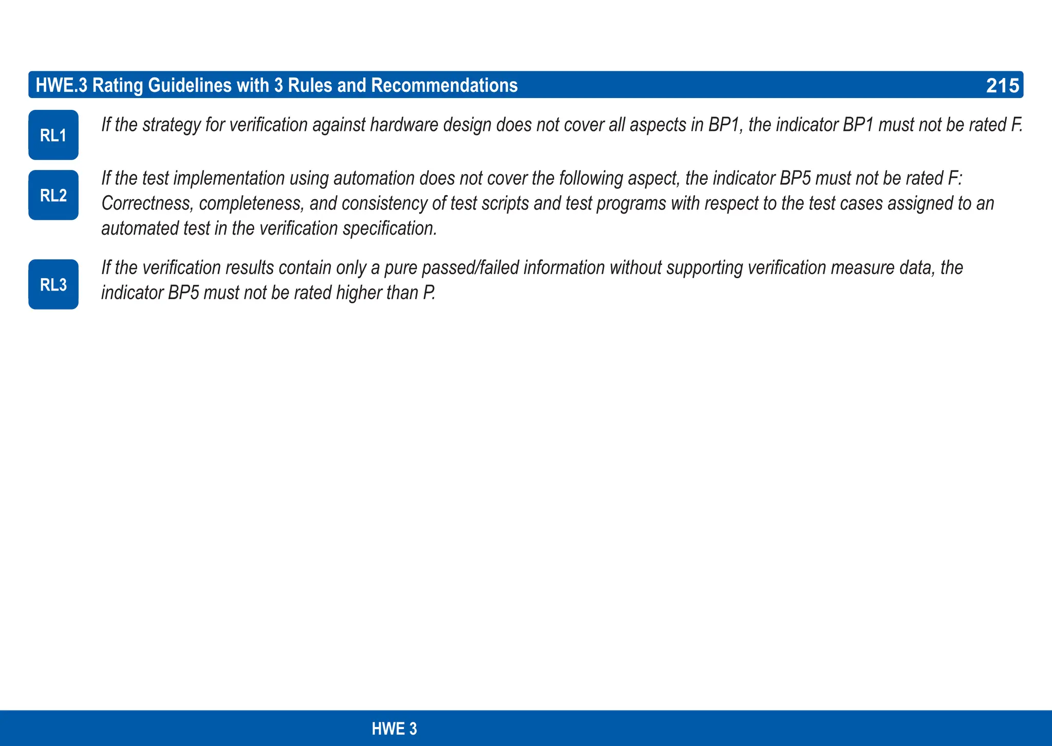
![216
ASPICE GUIDE
08-HW01 Verification plan [OUTCOME 1] 13-19 Review record [OUTCOME 6]
08-HW02 Verification specification [OUTCOME 2,4] 13-22 Traceability record [OUTCOM 6]
13-01 Acceptance record [OUTCOME 3] 13-HW01 Verification result [OUTCOME 5,7]
13-04 Communication record [OUTCOME 7]
HWE.4 Verification against Hardware Requirements
The purpose of the Verification against Hardware Requirements process is to ensure that the complete hardware is verified to provide
evidence for compliance with the hardware requirements.
Process outcomes – as a result of successful implementation of this process
1. A strategy for verification against hardware requirements including regression strategy consistent with the project plan and release
plan is developed, and suitability of measurement and verification equipment is ensured.
2. A specification for verifying the hardware according to the strategy for verification against hardware is developed that is suitable to
provide evidence for compliance with the hardware requirements.
3. Hardware design-compliant samples are received according to the strategy for verification against hardware.
4. Verification measures included in the verification specification are selected according to the verification strategy and the release plan.
5. The hardware is verified using the selected verification measures and the results of hardware requirements verifications are
recorded.
6. Consistency and bidirectional traceability are established between verification measures and hardware requirements.
Consistency and bidirectional traceability are established between verification measures and verification results.
7. Results of the verifications are summarized and communicated to all affected parties.
Output work products](https://image.slidesharecdn.com/aspice-guide-km2021-04-240204182441-58722c47/75/ASPICE-Guide-KM2021-04-pdf-216-2048.jpg)
![217
ASPICE GUIDE
Develop a strategy for the verification against hardware requirements. Develop a strategy for the verification against
hardware requirements consistent with the project plan and the release plan including
a) a definition of the verification scope [ISO 26262-8:2018 clause 9.4.1.1 b)]
b) identification of the hardware variants to be verified
c) definition of suitable measurement and verification equipment [ISO 26262-8:2018 clause 9.4.1.1 f)]
d) a regression strategy for verifying the hardware [ISO 26262-8:2018 clause 9.4.1.1 i)],
e) a definition of the criteria to select verification measures including
- the coverage of new or changed requirements
- the coverage of change requests
- the coverage of changes to the device under test
- the consideration of dependencies, based on the analysis of changes
- the selection of appropriate verification measures for regression verification
f) a definition of the methods for verification measure development including criteria for selection
[ISO 26262-8:2018 clause 9.4.1.1 c)]
g) a definition of how specific requirements regarding verification (e.g. test-specific stakeholder requirements)
are covered
h) required sequences of verification steps
i) an approach for the handling of failed verification [ISO 26262- 8:2018 clause 9.4.1.1 h)]
j) an approach for verification measure data handling
The reason for the existence of aspects a) to f) is given in Section 2 on ‘No separate guideline document’.
Hardware regression verification means verifying that a hardware item, which has not been changed, is not influenced
by a change of another hardware item.
HWE.4 with 8 Base practices
BP 1
217
1
2
HWE 4](https://image.slidesharecdn.com/aspice-guide-km2021-04-240204182441-58722c47/75/ASPICE-Guide-KM2021-04-pdf-217-2048.jpg)
![218
ASPICE GUIDE
A predefined number of verification measures to be repeated on any change might be defined in the regression strategy as
well, e.g. all safety relevant test cases.
The objective is to verify discrete hardware functionality, i.e. without software/mechanical functionality. However, for that
purpose mechanical elements, or suitable special test-software running on the hardware, might be needed as the verificati-
on environment.
The suitability of measurement and verification equipment may be dependent on e.g. the release stage such as the EMC
measurement of early samples intended to be done by non-certified labs.
For semiconductor development the strategy typically covers both Pre- and Post-Silicon verification against hardware
requirements.
Develop specification for the verification against hardware requirements. Develop the verification specification according
to the defined strategy. The verification specification shall
a) be suitable to provide evidence for compliance of the hardware with the hardware requirements
b) include a definition of entry and exit criteria for the verification [OUTCOME 2]
This typically includes pass/fail criteria for each verification measure.
For safety-related aspects the durability and robustness of hardware against environmental and operational stress factors
should be verified [ISO 26262-5:2018 clause 10.4.6]
In the case of safety-related development, additional safety-related verification measures should be determined by using
results of the safety analysis including faults and failure mode information [ISO 26262-9:2018, clause 8.4.7], see also
HWE.2 BP6 Note 22
HWE.4 with 8 Base practices 218
5
BP 1
BP 2
8
7
9
4
3
6](https://image.slidesharecdn.com/aspice-guide-km2021-04-240204182441-58722c47/75/ASPICE-Guide-KM2021-04-pdf-218-2048.jpg)
![219
ASPICE GUIDE
BP 3
HWE.4 with 8 Base practices 219
10
12
11
13
Ensure use of compliant samples. Ensure that the samples used for the verification against hardware requirements are
compliant with the corresponding production data, including special characteristics, provided by hardware design.
[OUTCOME 3]
Received evidence can be e.g. sample reports, record of visual inspection, ICT report.
Bill of materials-compliance alone does not automatically mean full production data compliance.
The party from which samples are obtained can be production, prototype and sample construction or build2print-suppliers.
If samples have deviations, or need to be reworked or modified, this information needs to be documented.
Production processes themselves are not in the scope of HWE PRM/PAM; the assumption is that the production process
itself is done correctly; for the purpose of getting correct samples, only process interfaces to the production processes are
in scope.
Select verification measures. Select verification measures from the verification specification according to the defined
strategy. The selection of verification measures shall
b) consider the intended use of the deliverable item (e.g. for EMV testing, for supporting software testing)
c) document the used selection criteria (as defined in the strategy)
d) be documented [OUTCOME 4]
Criteria for selection may be e.g.
• maturity of implementation of requirements
• regression strategy
• prioritization of requirements
Calculations and simulations are considered hardware design evaluation activities, see HWE.2 BP6
BP 4
14
15
HWE 4
16](https://image.slidesharecdn.com/aspice-guide-km2021-04-240204182441-58722c47/75/ASPICE-Guide-KM2021-04-pdf-219-2048.jpg)
![220
ASPICE GUIDE
HWE.4 with 8 Base practices
BP 8
220
Verify hardware. Verify the hardware using the selected verification measures according to the defined strategy. Record the
verification results including pass/fail status and corresponding verification measure data. [OUTCOME 5]
See Automotive SPICE® SUP.9 for handling of non-conformances
Establish bidirectional traceability. Establish bidirectional traceability between hardware requirements and verification
measures. Establish bidirectional traceability between verification measures and verification results. [OUTCOME 6]
Bidirectional traceability supports coverage, consistency and impact analysis.
Ensure consistency. Ensure consistency between hardware requirements and verification measures. [OUTCOME 6]
Consistency is supported by bidirectional traceability and can be demonstrated by review records.
Summarize and communicate results. Summarize the verification results and communicate them to all affected parties.
[OUTCOME 7]
Providing all necessary information from the verification measures in a summary supports other parties in taking
appropriate measures.
In the case large amounts of verification data may be generated (e.g. automated tests) then a meaningful summary
of the verification data as adequate evidence for each verification result can be provided.
BP 5
17
BP 6
18
BP 7
19
20
21](https://image.slidesharecdn.com/aspice-guide-km2021-04-240204182441-58722c47/75/ASPICE-Guide-KM2021-04-pdf-220-2048.jpg)
![221
ASPICE GUIDE
HWE.4 Rating Guidelines with 3 Rules
[HWE.4.RL.1] If the strategy for verification against hardware requirements does not cover all aspects in BP1, the indicator
BP1 must not be rated F.
[HWE.4.RL.2] If the test implementation using automation does not cover the following aspect, the indicator BP5 must not be
rated F:
• Correctness, completeness, and consistency of test scripts and test programs with respect to the test cases assigned
to an automated test in the verification specification.
[HWE.4.RL.3] If the verification results contain only a pure pass/fail information without supporting verification measure data,
the indicator BP5 must not be rated higher than P.
RL1
RL2
RL3
221
HWE 4](https://image.slidesharecdn.com/aspice-guide-km2021-04-240204182441-58722c47/75/ASPICE-Guide-KM2021-04-pdf-221-2048.jpg)
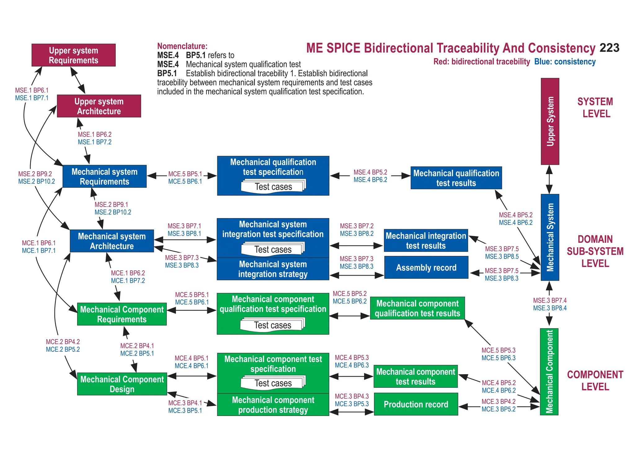
![224
ASPICE GUIDE
01-51 Application parameter [OUTCOME 1] 15-01 Analysis report [OUTCOME 2, 3, 4, 7]
13-04 Communication record [OUTCOME 8] 17-08 Interface requirements specification [1] [OUTCOME 1]
13-19 Review record [OUTCOME 6] 17-ME01 Mechanical system requirements specification [OUTCOME 1]
13-21 Change control record [OUTCOME 5, 7] 17-50 Verification criteria [OUTCOME 2]
13-22 Traceability record [OUTCOME 1, 6]
MSE.1 Mechanical System Requirements Analysis
The purpose of the Mechanical System Requirements Analysis process is to derive the mechanical system requirements from the
upper system requirements together with all affected stakeholders.
1. the mechanical system requirements are derived from the upper system requirements and the upper system architecture;
2. Note: If the mechanical system is the highest system the source of these requirements are the only the stakeholders, in other
cases the requirements’ source is the upper system requirements and the upper system architecture.
3. the mechanical system requirements are categorized and analyzed for correctness and verifiability;
4. the impact of mechanical system requirements on the operating environment is analyzed and communicated;
5. prioritization for implementing the mechanical system requirements is defined;
6. the mechanical system requirements are updated as needed;
7. consistency and bidirectional traceability are established between upper system requirements and mechanical system
requirements; and consistency and bidirectional traceability are established between upper system architecture and mechanical
system requirements;
8. the mechanical system requirements are evaluated for cost, schedule and technical impact; and
9. the mechanical system requirements are agreed and communicated to all affected stakeholders.
Output work products
Process outcomes – as a result of successful implementation of this process
Mechanical System Engineering](https://image.slidesharecdn.com/aspice-guide-km2021-04-240204182441-58722c47/75/ASPICE-Guide-KM2021-04-pdf-224-2048.jpg)
![225
ASPICE GUIDE
Specify mechanical system requirements.
Use the upper system requirements and the upper system architecture as well as changes to the upper system requirements
and architecture to identify the required functions and capabilities of the mechanical system. Specify functional and
non-functional mechanical system requirements in a mechanical system requirements specification. [OUTCOME 1, 5, 7]
Non-functional requirements may include e.g. production, maintenance, exchangeability of systems and components
in the field, logistic, packaging, sizing, weight, price per unit, producibility, environmental, design guidelines, modelling
guidelines and patents.
Mechanical system requirements should include tolerances as necessary.
Structure mechanical system requirements.
Structure the mechanical system requirements in the mechanical system requirements specification by e.g.
• grouping to project relevant clusters like architecture elements,
• sorting in a logical order for the project,
• categorizing based on relevant criteria for the project,
• prioritizing according to stakeholder needs.
[OUTCOME 2, 4]
Prioritizing typically includes the assignment of mechanical content to planned releases. Refer to SPL.2 BP1.
Analyze mechanical system requirements.
Analyze the specified mechanical system requirements including their interdependencies to ensure correctness, technical
feasibility and verifiability, and to support risk identification. Analyze the impact on cost, schedule and the technical impact.
[OUTCOME 2, 7]
The analysis of impact on cost, schedule and quality supports the adjustment of project estimates. Refer to MAN.3 BP5.
BP1
1
BP2
MSE.1 with 8 Base practices
BP3
2
3
4
225
MSE.1](https://image.slidesharecdn.com/aspice-guide-km2021-04-240204182441-58722c47/75/ASPICE-Guide-KM2021-04-pdf-225-2048.jpg)
![226
ASPICE GUIDE
Analyze the impact on the operating environment.
Analyze the impact that the mechanical system requirements will have on upper system elements and the operating
environment. [OUTCOME 3, 7]
Develop verification criteria.
Develop the verification criteria for each mechanical system requirement that define the qualitative and quantitative
measures for the verification of a requirement. [OUTCOME 2, 7]
Verification criteria demonstrate that a requirement can be verified within agreed constraints and is typically used as
the input for the development of the test cases or other verification measures that should demonstrate compliance with
the mechanical system requirements.
Verification which cannot be covered by testing is covered by SUP.2.
Establish bidirectional traceability.
1. Establish bidirectional traceability between upper system requirements and mechanical system requirements.
2. Establish bidirectional traceability between the upper system architecture and mechanical system requirements.
[OUTCOME 6]
Bidirectional traceability supports coverage, consistency and impact analysis.
BP4
5
BP5
MSE.1 with 8 Base practices
BP6
6
7
226](https://image.slidesharecdn.com/aspice-guide-km2021-04-240204182441-58722c47/75/ASPICE-Guide-KM2021-04-pdf-226-2048.jpg)
![227
ASPICE GUIDE
BP7
Ensure consistency.
1. Ensure consistency between upper system requirements and mechanical system requirements.
2. Ensure consistency between the upper system architecture and mechanical system requirements.
[OUTCOME 6]
Consistency is supported by bidirectional traceability and can be demonstrated by review records.
In case of mechanical development only, the upper system requirements and upper system architecture refer to
a given operating environment. In that case, consistency and bidirectional tracea-bility has to be ensured between
stakeholder requirements and mechanical system requirements.
Communicate agreed mechanical requirements.
Communicate the agreed mechanical system requirements and updates to mechanical system requirements to all relevant
stakeholders. [OUTCOME 8]
8
9
BP8
MSE.1 with 8 Base practices 227
MSE.1](https://image.slidesharecdn.com/aspice-guide-km2021-04-240204182441-58722c47/75/ASPICE-Guide-KM2021-04-pdf-227-2048.jpg)
![228
ASPICE GUIDE
04-ME01 Mechanical system architectural design [OUTCOME 1, 2, 3, 4, 5] 13-22 Traceability record [OUTCOME 5]
13-04 Communication record [OUTCOME 6] 17-08 Interface requirement specification [OUTCOME 3]
13-19 Review record [OUTCOME 5] 13-ME01 Characteristics classification record [OUTCOME 1]
MSE.2 Mechanical System Architectural Design
The purpose of the Mechanical System Architectural Design Process is to establish an architectural design and to identify which mecha-
nical system requirements are to be allocated to which elements of the mechanic, and to evaluate the mechanical system architectural
design against defined criteria.
1. a mechanical system architectural design is defined that identifies the elements of the mechanical system;
2. the mechanical system requirements are allocated to the elements of the mechanical system;
3. the interfaces of each mechanical system elements are defined;
4. the static and dynamic behaviour and design constraints of the mechanical system elements are defined;
5. consistency and bidirectional traceability are established between mechanical system requirements and mechanical system
architectural design; and
6. the mechanical system architectural design is agreed and communicated to all affected stakeholders.
Output work products
Process outcomes – as a result of successful implementation of this process](https://image.slidesharecdn.com/aspice-guide-km2021-04-240204182441-58722c47/75/ASPICE-Guide-KM2021-04-pdf-228-2048.jpg)
![229
ASPICE GUIDE
BP1
1
BP2
MSE.2 with 11 Base practices
BP3
2
3
4
BP4
Develop mechanical system architectural design.
Develop and document the mechanical system architectural design that specifies the elements of the mechanical system
with respect to functional and non-functional mechanical system requirements. [OUTCOME 1]
The mechanical system is decomposed into elements across appropriate hierarchical levels down to the mechanical
components (the elements on the lowest level of the mechanical system architectural design) that are described in the
mechanical component design.
Consider make, buy and reuse options.
Model-based development (e.g. FEM, SysML) may facilitate the collaboration of the different engineering domains.
Allocate mechanical system requirements.
Allocate all mechanical system requirements to the elements of the mechanical system architectural design. [OUTCOME 2]
Define interfaces of mechanical elements.
Identify, develop and document the interfaces of each mechanical system element. [OUTCOME 3]
Identify special characteristics.
Identify and document special characteristics of the mechanical system elements. [OUTCOME 1]
The identification of special characteristics is supported by e.g. simulation, risk analysis, sizing calculations.
Describe dynamic and static behaviour.
Evaluate and document the dynamic and static behaviour of and the interaction between mechanical.
system elements. [OUTCOME 4]
Static and dynamic behaviour is determined by e.g. stress, force, pressure, strain, temperature, operating modes
(open, closed, in motion, misuse, emergency, etc.)
BP5
5
229
MSE.2](https://image.slidesharecdn.com/aspice-guide-km2021-04-240204182441-58722c47/75/ASPICE-Guide-KM2021-04-pdf-229-2048.jpg)
![230
ASPICE GUIDE
BP6
BP7
MSE.2 with 11 Base practices
BP8
6
7
Consider, determine, and document design constraints.
Determine and document design constraints for all mechanical system elements and take them into account for creating
the mechanical system architecture. [OUTCOME 4]
Evaluate alternative mechanical system architectures.
Define evaluation criteria for architectural design. Evaluate alternative mechanical system architectures according to the
defined criteria. Record the rationale for the chosen mechanical system architecture. [OUTCOME 1, 2, 3, 4, 5]
Evaluation criteria may include quality characteristics (cost, weight, packaging, modularity, maintainability,
expandability, scalability, reliability, safety and usability) and results of make-buy-reuse analysis.
Verify mechanical system architectural design.
Ensure that the mechanical system architectural design meets all mechanical system requirements. [Outcomes 4, 5]
Verification of mechanical system architectural design may include FEA, simulation, or Product FMEA.
Establish bidirectional traceability.
1. Establish bidirectional traceability between mechanical system requirements and elements of the mechanical system
architectural design.
2. Establish bidirectional traceability between elements of the mechanical system architectural design and elements of the
system architectural design.
[OUTCOME 5]
Bidirectional traceability covers allocation of mechanical system requirements to the elements of the mechanical system
architectural design.
Bidirectional traceability supports coverage, consistency and impact analysis.
BP9
8
9
230](https://image.slidesharecdn.com/aspice-guide-km2021-04-240204182441-58722c47/75/ASPICE-Guide-KM2021-04-pdf-230-2048.jpg)
![231
ASPICE GUIDE
BP10
10
11
Ensure consistency.
1. Ensure consistency between mechanical system requirements and the mechanical system architectural design.
2. Ensure consistency between elements of the mechanical system architectural design and elements of the
system architectural design.
[OUTCOME 1, 2, 5, 6]
Consistency is supported by bidirectional traceability and can be demonstrated by review records.
Mechanical system requirements include mechanical system architectural requirements, refer to BP7.
Communicate agreed mechanical system architectural design.
Communicate the agreed mechanical system architectural design and updates to mechanical system architectural design
to all relevant stakeholders. [OUTCOME 6]
BP11
MSE.2 with 11 Base practices 231
MSE.2](https://image.slidesharecdn.com/aspice-guide-km2021-04-240204182441-58722c47/75/ASPICE-Guide-KM2021-04-pdf-231-2048.jpg)
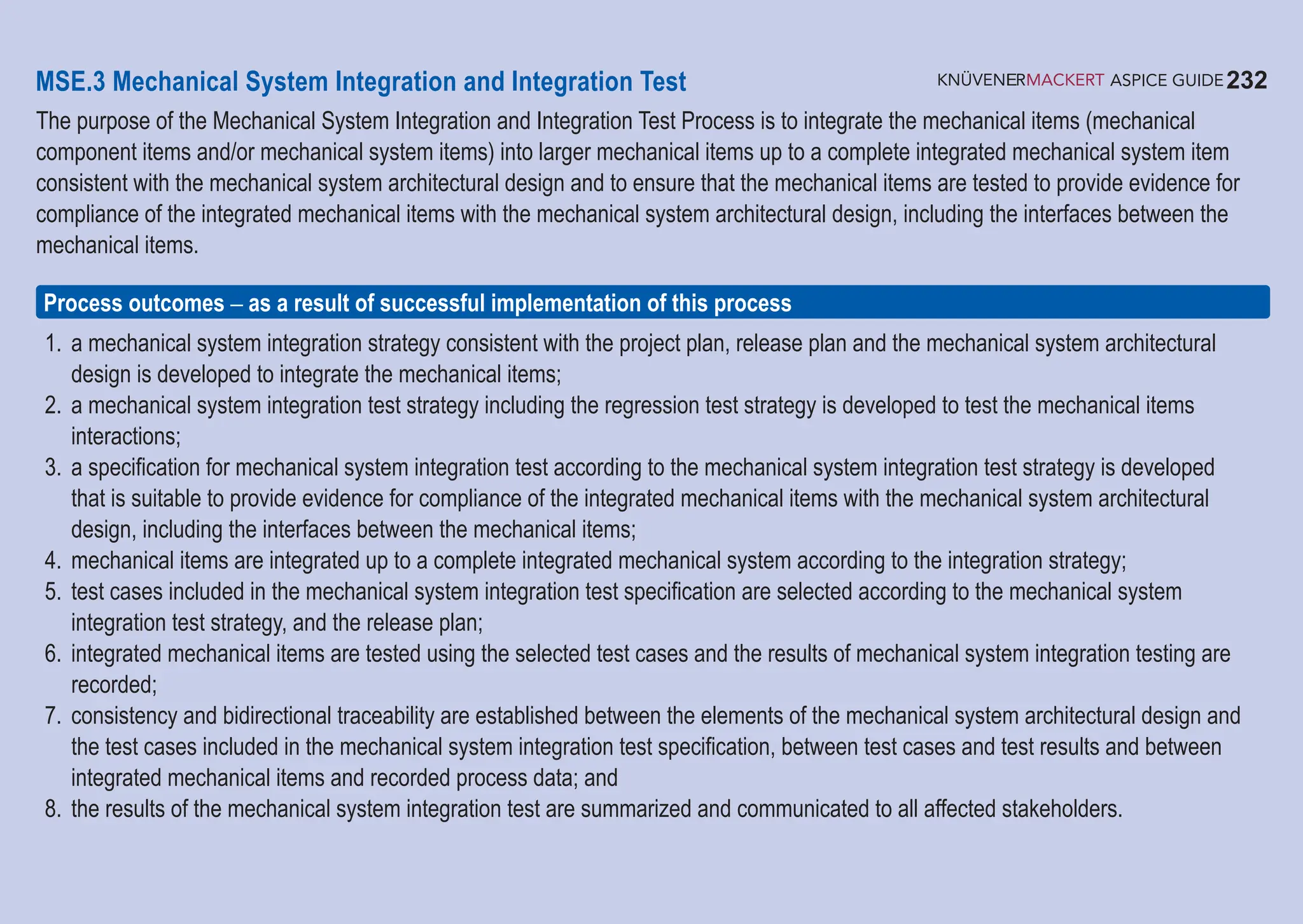
![233
ASPICE GUIDE
Output work products
08-ME01 Sample control plan [OUTCOME 1,2] 13-22 Traceability record [OUTCOME 7]
17-ME02 Assembly instruction [OUTCOME 1] 17-ME03 Bill of material (BOM, Build list) [OUTCOME 3, 4, 7]
13-ME02 Assembly record [OUTCOME 4] 11-ME01 Mechanical System [OUTCOME 4]
08-50 Test specification [OUTCOME 3,5] 13-04 Communication record [OUTCOME 8]
13-50 Test result [OUTCOME 6,8] 13-19 Review record [OUTCOME 7]
BP1
BP2
MSE.3 with 9 Base practices
BP3
Develop mechanical system integration strategy.
Develop a strategy for integrating mechanical sub-systems consistent with the project plan and the release plan. Identify
mechanical subsystems based on the mechanical system architectural design and define a sequence for integrating them.
[OUTCOME 1]
Develop mechanical system integration test strategy including regression test strategy.
Develop a strategy for testing the integrated mechanical item following the mechanical system integration strategy. This inclu-
des a regression test strategy for retesting integrated mechanical item if a mechanical item is changed. [OUTCOME 2]
Develop specification for mechanical system integration test.
Develop the test specification for mechanical system integration test including the test cases according to the mechanical
system integration test strategy for each integrated mechanical item. The test specification shall be suitable to provide
evidence for compliance of the integrated mechanical items with the mechanical system architectural design. [OUTCOME 3]
Compliance to the architectural design means that the specified integration tests are suitable to prove that the interfa-
ces between the mechanical items fulfill the specification (e.g. special characteristics) given by the mechanical system
architectural design.
1
233
MSE.3](https://image.slidesharecdn.com/aspice-guide-km2021-04-240204182441-58722c47/75/ASPICE-Guide-KM2021-04-pdf-233-2048.jpg)
![234
ASPICE GUIDE
BP6
Perform mechanical system integration test.
Perform the mechanical system integration test using the selected test cases. Record the integration test results and logs.
[OUTCOME 6]
See SUP.9 for handling of non-conformances
Capable test environment as defined in the test strategy needs to be available for performing mechanical system
integration and integration test.
Establish bidirectional traceability.
1. Establish bidirectional traceability between elements of the mechanical system architectural design and test cases
included in the mechanical system integration test specification.
2. Establish bidirectional traceability between test cases included in the mechanical system integration test specification
and mechanical system integration test results.
3. Establish bidirectional traceability between integrated mechanical items and recorded process data according to the
mechanical system integration strategy.
4. Establish bidirectional traceability between integrated mechanical items and the considered mechanical system item.
5. Establish bidirectional traceability between the mechanical integration test results and the integrated mechanical systems.
[OUTCOME 7]
Bidirectional traceability supports coverage, consistency and impact analysis.
BP7
2
3
4
BP5
BP4
MSE.3 with 9 Base practices
Integrate mechanical items.
Integrate the mechanical items to integrated mechanical system item according to the mechanical system integration
strategy and record process data according to the integration strategy. [OUTCOME 4]
Select test cases.
Select test cases from the mechanical system integration test specification. The selection of test cases shall have sufficient
coverage according to the mechanical system integration test strategy and the release plan. [OUTCOME 5]
234](https://image.slidesharecdn.com/aspice-guide-km2021-04-240204182441-58722c47/75/ASPICE-Guide-KM2021-04-pdf-234-2048.jpg)
![235
ASPICE GUIDE
MSE.3 with 9 Base practices
B8
BP9
Ensure consistency.
1. Ensure consistency between elements of the mechanical system architectural design and test cases included in
the mechanical system integration test specification.
2. Ensure consistency between test cases included in the mechanical system integration test speci-fication and
mechanical system integration test results.
3. Ensure consistency between integrated mechanical items and recorded process data according to the mechanical system
integration strategy.
4. Ensure consistency between integrated mechanical items and the considered mechanical sys-tem item.
5. Ensure consistency between the mechanical integration test results and the integrated mechan-ical systems.
[OUTCOME 7]
Consistency is supported by bidirectional traceability and can be demonstrated by review records.
Summarize and communicate results.
Summarize the mechanical system integration test results and communicate them to all affected stakeholders. [OUTCOME 8]
Providing all necessary information (e.g. test results, recorded process data) from the test case execution in a summary
enables stakeholders to judge the consequences.
6
5
235
MSE.3](https://image.slidesharecdn.com/aspice-guide-km2021-04-240204182441-58722c47/75/ASPICE-Guide-KM2021-04-pdf-235-2048.jpg)
![236
ASPICE GUIDE
MSE.4 Mechanical System Qualification Test
The purpose of the Mechanical System Qualification Test Process is to ensure that the integrated mechanical system is tested to
provide evidence for compliance with the mechanical system requirements.
1. a mechanical system qualification test strategy including regression test strategy consistent with the project plan and the release
plan is developed to test the integrated mechanical system;
2. a specification for mechanical system qualification test of the integrated mechanical system according to the mechanical system
qualification test strategy is developed that is suitable to provide evidence for compliance with the mechanical system requirements;
3. test cases included in the mechanical system qualification test specification are selected according to the mechanical system
qualification test strategy and the release plan;
4. the integrated mechanical system is tested using the selected test cases and the results of mechanical system qualification test
are recorded;
5. consistency and bidirectional traceability are established between mechanical system requirements and mechanical system
qualification test specification including test cases and between test cases and test results; and
6. results of the mechanical system qualification test are summarized and communicated to all affected stakeholders.
Process outcomes – as a result of successful implementation of this process
08-52 Test plan (DVP) [OUTCOME 1, 2, 6] 13-22 Traceability record [OUTCOME 5]
08-50 Test specification [OUTCOME 2, 3] 13-04 Communication record [OUTCOME 6]
13-50 Test result [OUTCOME 4, 6] 13-19 Review record [OUTCOME 5]
Output work products](https://image.slidesharecdn.com/aspice-guide-km2021-04-240204182441-58722c47/75/ASPICE-Guide-KM2021-04-pdf-236-2048.jpg)
![237
ASPICE GUIDE
BP1
BP2
MSE.4 with 7 Base practices
BP3
BP4
Develop mechanical system qualification test strategy including a regression test strategy.
Develop a strategy for mechanical system qualification testing consistent with the project plan and the release plan. This
includes a regression test strategy for retesting the integrated mechanical system if a mechanical subsystem is changed.
[OUTCOME 1]
Develop specification for mechanical system qualification test.
Develop the specification for mechanical system qualification testing including test cases based on the verification criteria
according to the mechanical system test strategy. The test specification shall be suitable to provide evidence for compliance
of the integrated mechanical system with the mechanical system requirements. [OUTCOME 2]
Select test cases.
Select test cases from the mechanical system qualification test specification. The selection of test cases shall have sufficient
coverage according to the mechanical system qualification test strategy and the release plan. [OUTCOME 3]
Test the integrated mechanical system.
Test the mechanical system using the selected test cases. Record the mechanical system qualification test results and logs.
[OUTCOME 4]
See SUP.9 for handling of non-conformances
Capable test environment as defined in the test strategy needs to be available for performing mechanical system
qualification testing.
2
1
237
MSE.4](https://image.slidesharecdn.com/aspice-guide-km2021-04-240204182441-58722c47/75/ASPICE-Guide-KM2021-04-pdf-237-2048.jpg)
![238
ASPICE GUIDE
BP5
BP6
MSE.4 with 7 Base practices
BP7
Establish bidirectional traceability.
1. Establish bidirectional traceability between mechanical system requirements and test cases included in the mechanical
system qualification test specification.
2. Establish bidirectional traceability between test cases included in the mechanical system qualification test specification
and mechanical system qualification test results.
3. Establish bidirectional traceability between the mechanical system qualification test results and the integrated
mechanical systems.
[OUTCOME 5]
Bidirectional traceability supports coverage, consistency and impact analysis.
Ensure consistency.
1. Ensure consistency between mechanical system requirements and test cases included in the mechanical system
qualification test specification.
2. Ensure consistency between test cases included in the mechanical system qualification test specification and mechanical
system qualification test results.
3. Ensure consistency between the mechanical system qualification test results and the integrated mechanical systems.
[OUTCOME 5]
Consistency is supported by bidirectional traceability and can be demonstrated by review records.
Summarize and communicate results.
Summarize the mechanical system qualification test results and communicate them to all affected stakeholders.
[OUTCOME 6]
Providing all necessary information from the test case execution in a summary enables stakeholders to judg
the consequences.
3
4
5
238](https://image.slidesharecdn.com/aspice-guide-km2021-04-240204182441-58722c47/75/ASPICE-Guide-KM2021-04-pdf-238-2048.jpg)

![240
ASPICE GUIDE
MCE.1 Mechanical Component Requirements Analysis
The purpose of the Mechanical Component Requirements Analysis process is to establish the requirements for the mechanical
component.
1. the mechanical component requirements are derived from the upper system requirements and upper system architecture;
2. mechanical component requirements are categorized and analyzed for completeness, correctness, and verifiability;
3. the impact of mechanical component requirements on the operating environment is analyzed;
4. prioritization for implementing the mechanical component requirements is defined;
5. the mechanical component requirements are updated as needed;
6. consistency and bidirectional traceability are established between upper system requirements and mechanical component require-
ments; and consistency and bidirectional traceability are established between upper system architectural design and mechanical
component requirements;
7. the mechanical component requirements are evaluated for cost, schedule and technical impact; and
8. the mechanical component requirements are agreed and communicated to all affected stakeholders.
Output work products
Process outcomes – as a result of successful implementation of this process
13-04 Communication record [OUTCOME 8] 15-01 Analysis report [OUTCOME 2, 3, 4, 7]
13-19 Review record [OUTCOME 6] 17-08 Interface requirements specification [OUTCOME 1]
13-21 Change control record [OUTCOME 5,7] 17-ME04 Mechanical component requirements specification [OUTCOME 1]
13-22 Traceability record [OUTCOME 1, 6] 17-50 Verification criteria [OUTCOME 2]
Mechanical Component Engineering](https://image.slidesharecdn.com/aspice-guide-km2021-04-240204182441-58722c47/75/ASPICE-Guide-KM2021-04-pdf-240-2048.jpg)
![241
ASPICE GUIDE
Specify mechanical component requirements.
Use the upper system requirements and the upper system architecture and changes to the upper system requirements
and the upper system architecture to identify the required functions and capabilities of the mechanical component. Specify
functional and non-functional mechanical component requirements in a mechanical component requirements specification.
[OUTCOME 1, 5, 7]
If the system requirements and the system architectural design refer to a given operating environment, then the
stakeholder requirements should be used as the basis for identifying the required functions and capabilities of the
mechanical component.
Non-functional requirements may include e.g. production, maintenance, logistic, environmental.
Structure mechanical component requirements.
Structure the mechanical component requirements in the mechanical component requirements specification by e.g.
• grouping to project relevant clusters,
• sorting in a logical order for the project,
• categorizing based on relevant criteria for the project,
• prioritizing according to stakeholder needs.
[OUTCOME 2, 4]
Prioritizing typically includes the assignment of mechanical content to planned releases. Refer to SPL.2 BP1.
BP1
BP2
MCE.1 with 8 Base practices
1
2
3
241
MCE.1](https://image.slidesharecdn.com/aspice-guide-km2021-04-240204182441-58722c47/75/ASPICE-Guide-KM2021-04-pdf-241-2048.jpg)
![242
ASPICE GUIDE
BP3
BP4
MCE.1 with 8 Base practices
4
BP5
5
Analyze mechanical component requirements.
Analyze the specified mechanical component requirements including their interdependencies to ensure correctness,
technical feasibility, producibility and verifiability, and to support risk identification. Analyze the impact on cost, schedule
and the technical impact. [OUTCOME 2, 7]
The analysis of impact on cost, schedule and quality supports the adjustment of project esti-mates. Refer to MAN.3 BP5.
Analyze the impact on the operating environment.
Analyze the impact that the mechanical component requirements will have on interfaces of system elements and the
operating environment. [OUTCOME 3, 7]
Develop verification criteria.
Develop the verification criteria for each mechanical component requirement that define the qualitative and quantitative
measures for the verification of a requirement. [OUTCOME 2, 7]
Verification criteria demonstrate that a requirement can be verified within agreed constraints and are typically used as
the input for the development of the test cases or other verification measures that should demonstrate compliance with
the mechanical component requirements.
Verification which cannot be covered by testing is covered by SUP.2.
Establish bidirectional traceability.
1. Establish bidirectional traceability between upper system requirements and mechanical component requirements.
2. Establish bidirectional traceability between the upper system architecture and mechanical component requirements.
[OUTCOME 6]
Redundancy should be avoided by establishing a combination of the approaches BP6.1 and BP6.2 that covers the
project and the organizational needs.
Bidirectional traceability supports coverage, consistency and impact analysis.
6
7
8
BP6
242](https://image.slidesharecdn.com/aspice-guide-km2021-04-240204182441-58722c47/75/ASPICE-Guide-KM2021-04-pdf-242-2048.jpg)
![243
ASPICE GUIDE
Ensure consistency.
1. Ensure consistency between upper system requirements and mechanical component requirements.
2. Ensure consistency between the upper system architecture and mechanical component requirements.
[OUTCOME 6]
Consistency is supported by bidirectional traceability and can be demonstrated by review records.
If the system requirements and the system architectural design refer to a given operating environment, then the
stakeholder requirements should be used as the basis for identifying the required functions and capabilities of the
mechanical component.
Communicate agreed mechanical component requirements.
Communicate the agreed mechanical component requirements and updates to mechanical component requirements to
all relevant stakeholders. [OUTCOME 8]
BP7
BP8
MCE.1 with 8 Base practices
9
10
243
MCE.1](https://image.slidesharecdn.com/aspice-guide-km2021-04-240204182441-58722c47/75/ASPICE-Guide-KM2021-04-pdf-243-2048.jpg)
![244
ASPICE GUIDE
MCE.2 Mechanical Component Design
The purpose of the Mechanical Component Design process is to provide an evaluated design for the mechanical component.
1. a design is developed that describes the mechanical component;
2. interfaces of the mechanical component are defined;
3. consistency and bidirectional traceability are established between mechanical component requirements and mechanical component
design; and consistency and bidirectional traceability are established between upper system architecture and mechanical component
design; and
4. the mechanical component design is agreed and communicated to all affected stakeholders.
Output work products
Process outcomes – as a result of successful implementation of this process
04-ME02 Mechanical component design [OUTCOME 1,2] 13-04 Communication record [OUTCOME 4]
13-22 Traceability record [OUTCOME 3]](https://image.slidesharecdn.com/aspice-guide-km2021-04-240204182441-58722c47/75/ASPICE-Guide-KM2021-04-pdf-244-2048.jpg)
![245
ASPICE GUIDE
Develop mechanical component design.
Develop a design for the mechanical component using the functional and non-functional mechanical component
requirements including interfaces. [OUTCOME 1]
While developing the mechanical component design the requirements and data relevant for production are identified
and documented.
Non-functional requirements may include e.g. price per unit, maintenance, logistic, packaging, size, weight,
manufacturability, environmental constraints, design guidelines, modelling guidelines, failure times.
Design for Manufacturing and Design for Assembly may be used to ensure manufacturability.
Evaluate mechanical component design.
Evaluate the mechanical component design in terms of interaction, criticality, technical complexity, risks, measurability
and verifiability. [OUTCOME 1,2]
The results of the evaluation can be used as input for test against mechanical component design.
Verify mechanical component design.
Ensure that the mechanical component design meets all mechanical component requirements. [OUTCOMES 4, 5]
Verification of mechanical component design may include FEA, simulation, or Product FMEA.
BP1
BP2
MCE.2 with 6 Base practices
1
2
4
3
BP3
245
MCE.2](https://image.slidesharecdn.com/aspice-guide-km2021-04-240204182441-58722c47/75/ASPICE-Guide-KM2021-04-pdf-245-2048.jpg)
![246
ASPICE GUIDE
Establish bidirectional traceability.
1. Establish bidirectional traceability between mechanical component requirements and mechanical component design.
2. Establish bidirectional traceability between the mechanical system architectural design and mechanical component design.
[OUTCOME 3]
Redundancy should be avoided by establishing a combination of the approaches BP4.1 and
BP4.2 that covers the project and the organizational needs.
Bidirectional traceability supports coverage, consistency and impact analysis.
BP4
BP5
MCE.2 with 6 Base practices
5
BP6
6
Ensure consistency.
1. Ensure consistency between mechanical component requirements and mechanical component design.
2. Ensure consistency between the mechanical system architectural design and mechanical component design.
[OUTCOME 3]
Consistency is supported by bidirectional traceability and can be demonstrated by review records.
Communicate agreed mechanical component design.
Communicate the agreed mechanical component design and updates to the mechanical component design to all relevant
stakeholders. [OUTCOME 4]
7
246](https://image.slidesharecdn.com/aspice-guide-km2021-04-240204182441-58722c47/75/ASPICE-Guide-KM2021-04-pdf-246-2048.jpg)

![248
ASPICE GUIDE
MCE.3 Mechanical Component Sample Production
The purpose of the Mechanical Component Sample Production process is to produce a mechanical component item that reflects
properly the mechanical component design and mechanical component production strategy.
1. a mechanical component production strategy is developed, communicated to, and agreed on with all affected stakeholders,
2. mechanical component items are produced according to the mechanical component design,
3. bidirectional traceability are established between the produced mechanical component and recorded process data according
to the mechanical component production strategy; and consistency and bidirectional traceability are established between
recorded process data and the mechanical component production strategy (control plan), and
4. information gathered during production is communicated to all affected stakeholders.
Process outcomes – as a result of successful implementation of this process
Output work products
11-ME02 Mechanical Component [OUTCOME 1,2] 13-22 Traceability record [3] [OUTCOME 3]
19-ME01 Production strategy [OUTCOME 1] 13-04 Communication record [OUTCOME 4]
13-ME03 Production record [OUTCOME 2,4] 15-01 Analysis report [OUTCOME 4]
(Containing analyses results of e.g. suitability of chosen
production method regarding effectiveness, timing, cost)](https://image.slidesharecdn.com/aspice-guide-km2021-04-240204182441-58722c47/75/ASPICE-Guide-KM2021-04-pdf-248-2048.jpg)
![249
ASPICE GUIDE
Develop mechanical component production strategy.
Develop a strategy for production of the mechanical component item. The mechanical component production strategy
shall be consistent with the mechanical component design, project plan (e.g. estimation of number of built items needed),
release plan (e.g. definition of releases and their content), and test strategy (e.g. mapping of test methods to releases).
[OUTCOME 1] The mechanical component production strategy may contain the definition of the production method(s),
verification method(s) (control plan).
Agree on mechanical component production strategy.
Communicate the agreed mechanical component production strategy between all involved stakeholders (e.g. engineering,
sample shop, production). [OUTCOME 1]
The communication of the mechanical component production strategy to suppliers is handled by ACQ.4 Supplier
monitoring.
Ensure and support production of mechanical components.
Ensure and support production of mechanical component items according to:
• the mechanical component design
• mechanical component production strategy
• the requirements and data relevant for production.
Record process data according to the mechanical component production strategy. [OUTCOME 2, 4]
Production here means only sample phases (e.g. prototype building, pre-series production) and does not cover the
process of industrialization.
BP1
BP2
MCE.3 with 6 Base practices
1
2
BP3
249
MCE.3](https://image.slidesharecdn.com/aspice-guide-km2021-04-240204182441-58722c47/75/ASPICE-Guide-KM2021-04-pdf-249-2048.jpg)
![250
ASPICE GUIDE
Establish bidirectional traceability.
1. Establish bidirectional traceability between mechanical component production strategy and mechanical component design.
2. Establish bidirectional traceability between the produced mechanical component item and recorded process data
according to the mechanical component production strategy.
3. Establish bidirectional traceability between recorded process data and mechanical component production strategy
(control plan).
[OUTCOME 3]
Bidirectional traceability supports coverage, consistency and impact analysis.
BP4
BP5
MCE.3 with 6 Base practices
3
Ensure consistency.
1. Ensure consistency between recorded process data and mechanical component production strategy (control plan).
2. Ensure consistency between produced mechanical component item and recorded process data according to the
mechanical component production strategy.
3. Ensure consistency between recorded process data and mechanical component production strategy (control plan).
[OUTCOME 3]
Consistency is supported by bidirectional traceability and can be demonstrated by review records.
4
250](https://image.slidesharecdn.com/aspice-guide-km2021-04-240204182441-58722c47/75/ASPICE-Guide-KM2021-04-pdf-250-2048.jpg)
![251
ASPICE GUIDE
BP6 Provide feedback to all affected stakeholders
Communicate information gathered during the production of the mechanical component to all affected stakeholders.
[OUTCOME 4]
These information may contain:
• Capability of chosen production method
• Manufacturability of the mechanical component
• Improvement potentials for future releases
• Process data and information
See SUP.9 for handling of non-conformances
The communication of information mentioned above is handled by ACQ.4 Supplier monitoring in case of production
at a supplier’s site.
Affected stakeholders may be:
• Industrialization
• Series production
• Mechanical engineering
• Project management
MCE.3 with 6 Base practices
5
6
251
MCE.3](https://image.slidesharecdn.com/aspice-guide-km2021-04-240204182441-58722c47/75/ASPICE-Guide-KM2021-04-pdf-251-2048.jpg)
![252
ASPICE GUIDE
MCE.4 Test against Mechanical Component Design
The purpose of the Test against mechanical component design process is to test the mechanical component item to provide evidence for
compliance of the mechanical component item with the mechanical component design.
1. a strategy for test against mechanical component design including regression test strategy is developed;
2. a specification for test against mechanical component design is developed according to the strategy for test against mechanical
component design that is suitable to provide evidence for compliance of the mechanical component item with the mechanical
component design;
3. test cases included in the test specification for test against mechanical component design are selected according to the test
strategy for test against the mechanical component design and the release plan;
4. the mechanical component item is tested according to the strategy for test against mechanical component design and the test
specification for test against mechanical component design and the results are recorded;
5. consistency and bidirectional traceability are established between the mechanical component design and the test specification
for test against mechanical component design as well as between the test specification for test against mechanical component
design and test results; and
6. results of the test against mechanical component design are summarized and communicated to all affected stakeholders.
Process outcomes – as a result of successful implementation of this process
Output work products
08-50 Test specification [OUTCOME 2] 13-19 Review record [OUTCOME 3, 4]
08-52 Test plan [OUTCOME 1, 6] 13-22 Traceability record [OUTCOME 4]
13-04 Communication record [OUTCOME 6] 13-50 Test result [OUTCOME 3, 5, 6]](https://image.slidesharecdn.com/aspice-guide-km2021-04-240204182441-58722c47/75/ASPICE-Guide-KM2021-04-pdf-252-2048.jpg)
![253
ASPICE GUIDE
Develop strategy for test against mechanical component design including regression test strategy.
Develop a strategy for test against mechanical component design including regression test strategy for retest if the
mechanical component design is changed. The test strategy shall define how to provide evidence for compliance of the
mechanical component item with the mechanical component design. [OUTCOME 1]
The test strategy shall contain a planning of needed items for testing and the allocation of tests to be performed within
different releases. The needed amount of items for dedicated tests shall consider that random and systematic faults
have to be detected.
Develop test specification for test against mechanical component design.
Develop test specification for test against mechanical component design including test cases that are suitable to provide
evidence for compliance of the mechanical component item with the mechanical component design according to the test
strategy. [OUTCOME 2]
Select test cases.
Select test cases from the test specification for test against mechanical component design. The selection of test cases shall
have sufficient coverage according to the test strategy for test against mechanical component design and the release plan.
[OUTCOME 3]
Test mechanical component item.
Test the mechanical component item using the test specification for test against mechanical component design according to
the strategy for test against mechanical component design. Record the test results and measured values. [OUTCOME 4]
See SUP.9 for handling of non-conformances.
Capable test environment as defined in the test strategy needs to be available for performing test against mechanical
component design.
BP1
BP2
MCE.4 with 7 Base practices
1
BP3
2
3
BP4
253
MCE.4](https://image.slidesharecdn.com/aspice-guide-km2021-04-240204182441-58722c47/75/ASPICE-Guide-KM2021-04-pdf-253-2048.jpg)
![254
ASPICE GUIDE
Establish bidirectional traceability.
1. Establish bidirectional traceability between the mechanical component design and the mechanical component test
specification for test against mechanical component design.
2. Establish bidirectional traceability between the test results and tested mechanical component items.
3. Establish bidirectional traceability between test cases included in the mechanical component test specification and
mechanical component test results.
[OUTCOME 5]
Bidirectional traceability supports coverage, consistency and impact analysis.
BP5
MCE.4 with 7 Base practices
4
BP6
Ensure consistency.
1. Ensure consistency between the mechanical component design and the test specification for test against mechanical
component design.
2. Ensure consistency between the test results and tested mechanical component items.
3. Ensure consistency between test cases included in the mechanical component test specification and mechanical
component test results.
[OUTCOME 5]
Consistency is supported by bidirectional traceability and can be demonstrated by review records.
Summarize and communicate results.
Summarize the test results and communicate them to all affected stakeholders. [OUTCOME 6]
Providing all necessary information from the test case execution in a summary enables stakeholders to judge
the consequences.
5
BP7
6
254](https://image.slidesharecdn.com/aspice-guide-km2021-04-240204182441-58722c47/75/ASPICE-Guide-KM2021-04-pdf-254-2048.jpg)

![256
ASPICE GUIDE
MCE.5 Test against Mechanical Component Requirements
The purpose of the Test against Mechanical Component Requirements process is to test the mechanical component to provide evidence
for compliance of the mechanical component with the mechanical component requirements.
1. a strategy for the test against mechanical component requirements including regression test strategy consistent with the project
plan and the release plan is developed;
2. a specification for the test against mechanical component requirements is developed according to the strategy for the test against
mechanical component requirements that is suitable to provide evidence for compliance of the mechanical component with the
mechanical component requirements;
3. test cases included in the test specification for the test against mechanical component requirements are selected according to the
test strategy for the test against mechanical component requirements and the release plan
4. the mechanical component is tested according to the strategy for the test against mechanical component requirements and the
test specification for the test against mechanical component requirements, and the results are recorded;
5. consistency and bidirectional traceability are established between the mechanical component requirements and the test
specification for the test against mechanical component requirements as well as between the test specification for the test against
mechanical component requirements and test results; and
6. results of the test against mechanical component requirements are summarized and communicated to all affected stakeholders.
Process outcomes – as a result of successful implementation of this process
Output work products
08-50 Test specification [OUTCOME 2, 6] 13-19 Review record [OUTCOME 3, 4]
08-52 Test plan [OUTCOME 1, 6] 13-22 Traceability record [OUTCOME 4]
13-04 Communication record [OUTCOME 6] 13-50 Test result [OUTCOME 3, 5]](https://image.slidesharecdn.com/aspice-guide-km2021-04-240204182441-58722c47/75/ASPICE-Guide-KM2021-04-pdf-256-2048.jpg)
![257
ASPICE GUIDE
Develop strategy for the test against mechanical component requirements including regression test strategy.
Develop a strategy for the test against mechanical component requirements consistent with the project plan and the release
plan. This includes a regression test strategy for retesting the mechanical component if it has been changed. [OUTCOME 1]
The test strategy shall include a plan of which items need to be tested and the allocation of tests to be performed within
different releases. The needed amount of items for dedicated tests shall consider that random and systematic faults have
to be detected.
Develop test specification for the test against mechanical component requirements.
Develop test specification including test cases for the test against mechanical component requirements that are suitable to
provide evidence for compliance of the mechanical component with the mechanical component requirements according
to the test strategy. [OUTCOME 2]
Select test cases.
Select test cases from the test specification for the test against mechanical component requirements. The selection of test
cases shall have sufficient coverage according to the test strategy for the test against mechanical component requirements
and the release plan. [OUTCOME 5]
Test the mechanical component.
Test the mechanical component using the test specification for the test against mechanical component requirements
according to the strategy for the test against mechanical component requirements. Record the test results and measured
values. [OUTCOME 3]
See SUP.9 for handling of non-conformances.
Capable test environment as defined in the test strategy needs to be available for performing test against mechanical
component requirements.
BP1
MCE.5 with 7 Base practices
1
BP2
BP3
2
3
BP4
257
MCE.5](https://image.slidesharecdn.com/aspice-guide-km2021-04-240204182441-58722c47/75/ASPICE-Guide-KM2021-04-pdf-257-2048.jpg)
![258
ASPICE GUIDE
Establish bidirectional traceability.
1. Establish bidirectional traceability between the mechanical component requirements and the test specification for test
against mechanical component requirements.
2. Establish bidirectional traceability between the test specification for the test against mechanical component requirements
and test results.
3. Establish bidirectional traceability between the mechanical component qualification test results and the tested mechanical
component items.
[OUTCOME 4]
Bidirectional traceability supports coverage, consistency and impact analysis.
BP5
MCE.5 with 7 Base practices
4
BP6
Ensure consistency.
1. Ensure consistency between the mechanical component requirements and the test specification for the test against
mechanical component requirements.
2. Ensure consistency between the test specification for the test against mechanical component requirements and test
results.
3. Ensure consistency between the mechanical component qualification test results and the tested mechanical component
items.
[OUTCOME 4]
Consistency is supported by bidirectional traceability and can be demonstrated by review records.
Summarize and communicate results.
Summarize the test results and communicate them to all affected stakeholders. [OUTCOME 6]
Providing all necessary information from the test case execution in a summary enables stakeholders to judge the
consequences.
5
6
BP7
258](https://image.slidesharecdn.com/aspice-guide-km2021-04-240204182441-58722c47/75/ASPICE-Guide-KM2021-04-pdf-258-2048.jpg)

![260
ASPICE GUIDE
Process capability Level 1: Performed process
The implemented process achieves its process purpose. The following process attribute demonstrates the achievement of this level
The process performance process attribute is a measure of the extent to which the process purpose is achieved. As a result of full
achievement of this attribute:
a) the process achieves its defined outcomes
PA 1.1 Process performance process attribute
GP
1.1.1
Achieve the process outcomes [ACHIEVEMENT a]
Achieve the intent of the base practices. Produce work products that evidence the process outcomes.
Generic practices 1.1.1
Generic resources
Resources are used to achieve the intent of process specific base practices [ACHIEVEMENT a]](https://image.slidesharecdn.com/aspice-guide-km2021-04-240204182441-58722c47/75/ASPICE-Guide-KM2021-04-pdf-260-2048.jpg)
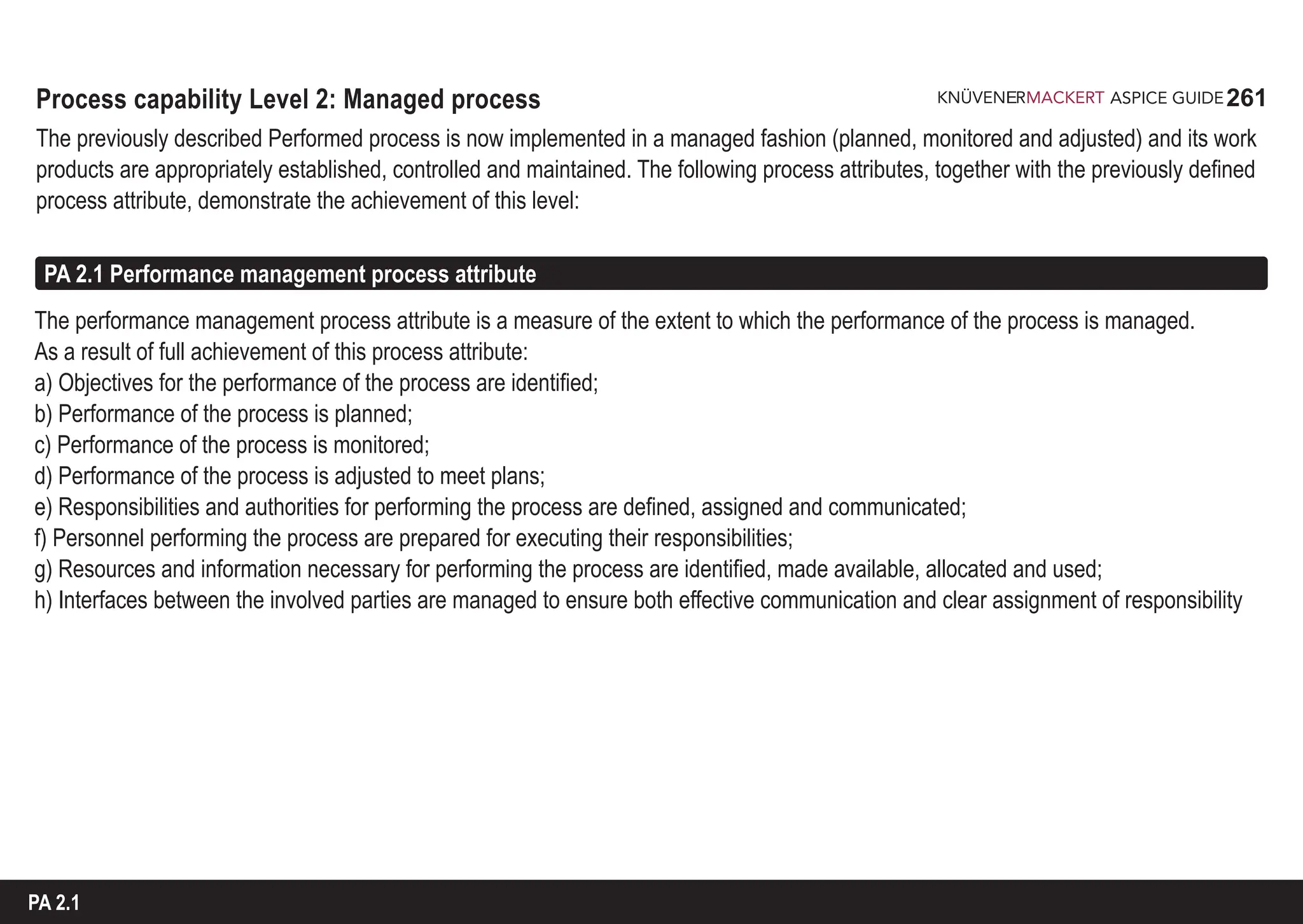
![262
ASPICE GUIDE
GP
2.1.2
GP
2.1.1
Identify the objectives for the performance of the process. [ACHIEVEMENT a]
Performance objectives are identified based on process requirements.
The scope of the process performance is defined.
Assumptions and constraints are considered when identifying the performance objectives.
Performance objectives may include
(1) timely production of artifacts meeting the defined quality criteria,
(2) process cycle time or frequency
(3) resource usage; and
(4) boundaries of the process.
At minimum, process performance objectives for resources, effort and schedule should be stated.
Plan the performance of the process to fulfill the identified objectives. [ACHIEVEMENT b]
Plan(s) for the performance of the process are developed.
The process performance cycle is defined.
Key milestones for the performance of the process are established.
Estimates for process performance attributes are determined and maintained.
Process activities and tasks are defined.
Schedule is defined and aligned with the approach to performing the process.
Process work product reviews are planned.
Generic practices 2.1.1 - 2.1.2
1
2
262
215: CL2.RL.1-4
216: CL2.RL.5-9
223: CL2.RL.22](https://image.slidesharecdn.com/aspice-guide-km2021-04-240204182441-58722c47/75/ASPICE-Guide-KM2021-04-pdf-262-2048.jpg)
![263
ASPICE GUIDE
GP
2.1.4
Generic practices 2.1.3 - 2.1.5 263
PA 2.1
GP
2.1.3
Monitor the performance of the process against the plans. [ACHIEVEMENT c]
The process is performed according to the plan(s).
Process performance is monitored to ensure planned results are achieved and to identify possible deviations.
Adjust the performance of the process. [ACHIEVEMENT d]
Process performance issues are identified.
Appropriate actions are taken when planned results and objectives are not achieved.
The plan(s) are adjusted, as necessary.
Rescheduling is performed as necessary.
Define responsibilities and authorities for performing the process. [ACHIEVEMENT e]
Responsibilities, commitments and authorities to perform the process are defined, assigned and communicated.
Responsibilities and authorities to verify process work products are defined and assigned.
The needs for process performance experience, knowledge and skills are defined.
217: CL2.RL.10-12
223: CL2.RL.23
218: CL2.RL.13-14
223: CL2.RL.24-26
GP
2.1.5
64: DID.RL.4
219: CL2.RL.15-17](https://image.slidesharecdn.com/aspice-guide-km2021-04-240204182441-58722c47/75/ASPICE-Guide-KM2021-04-pdf-263-2048.jpg)
![264
ASPICE GUIDE
Generic practices 2.1.6 - 2.1.7 264
GP
2.1.6
Identify, prepare, and make available resources to perform the process according to plan. [ACHIEVEMENT f, g]
The human and infrastructure resources, necessary for performing the process are identified, made available, allocated
and used.
The individuals performing and managing the process are prepared by training, mentoring, or coaching to execute their
responsibilities.
The information necessary to perform the process is identified and made available.
Manage the interfaces between involved parties. [ACHIEVEMENT h]
The individuals and groups involved in the process performance are determined.
Responsibilities of the involved parties are assigned.
Interfaces between the involved parties are managed.
Communication is assured between the involved parties.
Communication between the involved parties is effective.
GP
2.1.7
64: DID.RL.5
220: CL2.RL.18-19
224: CL2.RL.27-28
43: SAC.RC.1
64: DID.RL.7
221: CL2.RL.20-21
224: CL2.RC.3](https://image.slidesharecdn.com/aspice-guide-km2021-04-240204182441-58722c47/75/ASPICE-Guide-KM2021-04-pdf-264-2048.jpg)
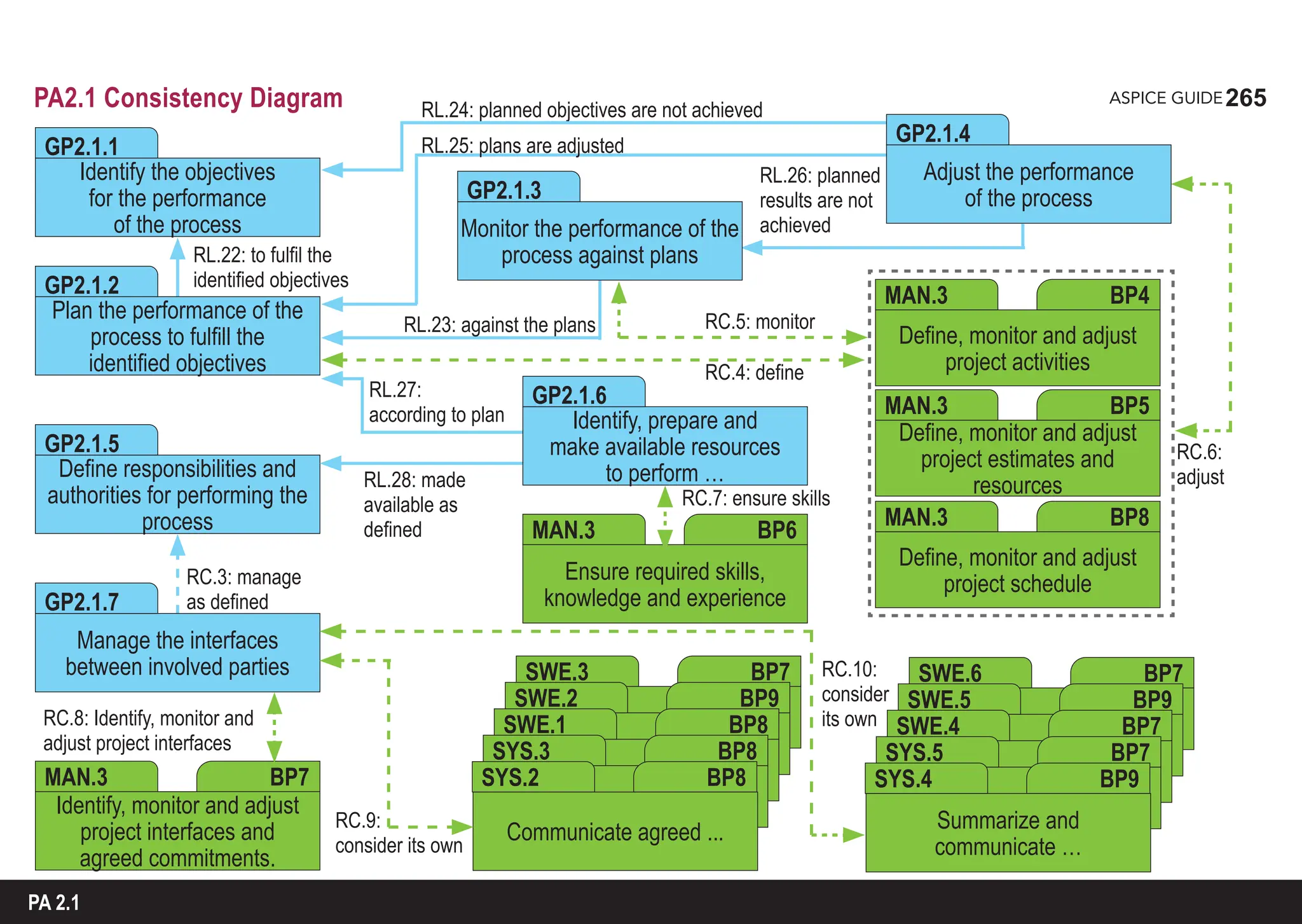
![266
ASPICE GUIDE
PA 2.2 Work product management process attribute
The work product management process attribute is a measure of the extent to which the work products produced by the process are
appropriately managed. As a result of full achievement of this process attribute:
a) Requirements for the work products of the process are defined;
b) Requirements for documentation and control of the work products are defined;
c) Work products are appropriately identified, documented, and controlled;
d) Work products are reviewed in accordance with planned arrangements and adjusted as necessary to meet requirements.
Requirements for documentation and control of work products may include requirements for the identification of changes and
revision status, approval and re-approval of work products, distribution of work products, and for making relevant versions of
applicable work products available at points of use.
The work products referred to in this clause are those that result from the achievement of the process purpose through the
process outcomes.
1
2
GP
2.2.1
Generic practices 2.2.1
Define the requirements for the work products. [ACHIEVEMENT a]
The requirements for the work products to be produced are defined.
Requirements may include defining contents and structure.
Quality criteria of the work products are identified.
Appropriate review and approval criteria for the work products are defined.
266
65: DID.RL.8
227f: CL2.RL.29-33](https://image.slidesharecdn.com/aspice-guide-km2021-04-240204182441-58722c47/75/ASPICE-Guide-KM2021-04-pdf-266-2048.jpg)
![267
ASPICE GUIDE
GP
2.2.3
GP
2.2.2
Generic practices 2.2.2 - 2.2.3 267
PA 2.2
64: DID.RL.6
228: CL2.RL.34
232: CL2.RL.40
Define the requirements for documentation and control of the work products. [ACHIEVEMENT b]
Requirements for the documentation and control of the work products are defined. Such requirements may include
requirements for
(1) distribution,
(2) identification of work products and their components and
(3) traceability.
Dependencies between work products are identified and understood.
Requirements for the approval of work products to be controlled are defined.
Identify, document and control the work products. [ACHIEVEMENT c]
The work products to be controlled are identified.
Change control is established for work products.
The work products are documented and controlled in accordance with requirements.
Versions of work products are assigned to product configurations as applicable.
The work products are made available through appropriate access mechanisms.
The revision status of the work products may readily be ascertained.](https://image.slidesharecdn.com/aspice-guide-km2021-04-240204182441-58722c47/75/ASPICE-Guide-KM2021-04-pdf-267-2048.jpg)
![268
ASPICE GUIDE
Generic practices 2.2.4 268
GP
2.2.4
Review and adjust work products to meet the defined requirements. [ACHIEVEMENT d]
Work products are reviewed against the defined requirements in accordance with planned arrangements.
Issues arising from work product reviews are resolved.](https://image.slidesharecdn.com/aspice-guide-km2021-04-240204182441-58722c47/75/ASPICE-Guide-KM2021-04-pdf-268-2048.jpg)
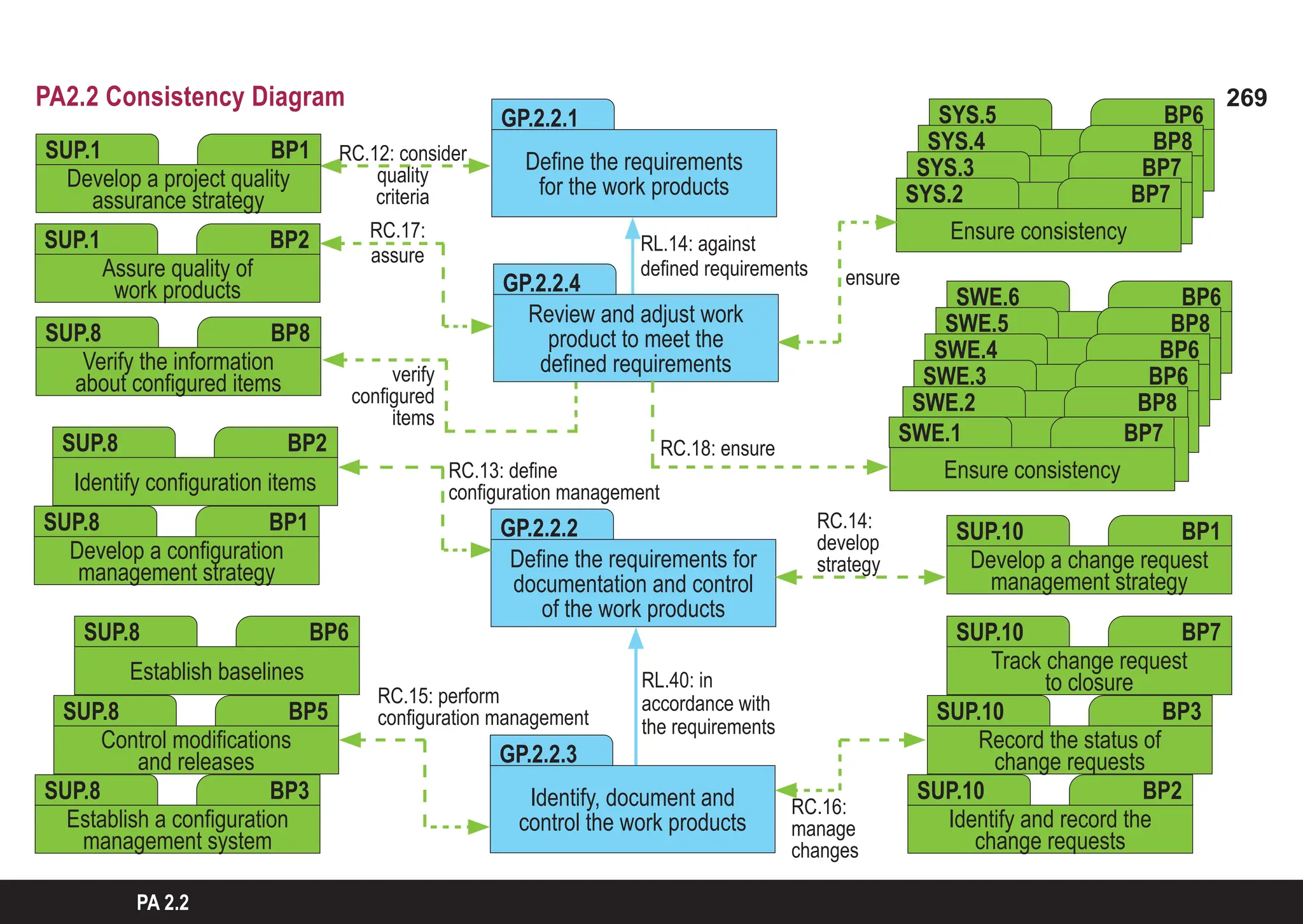
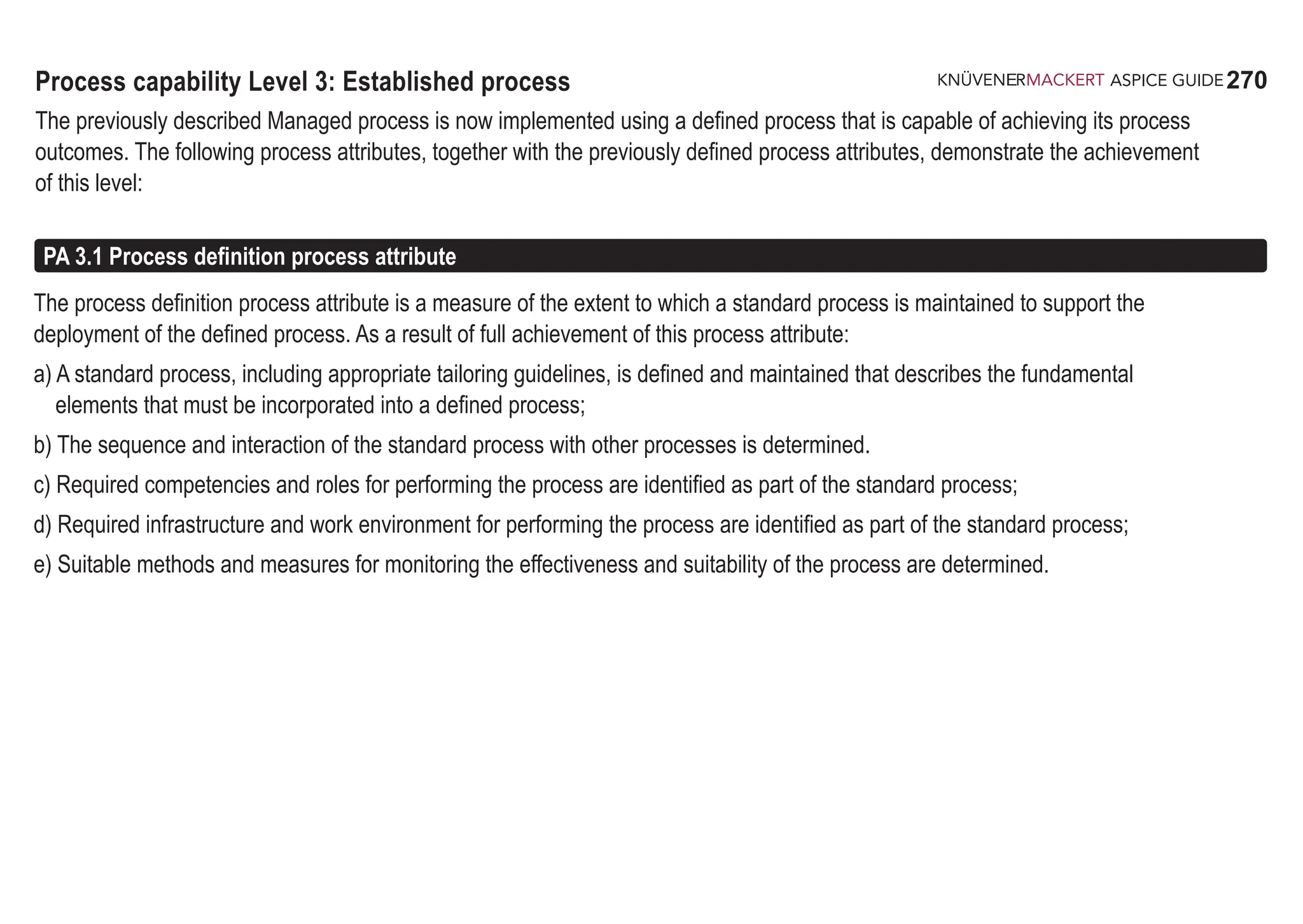
![271
ASPICE GUIDE
GP
3.1.1
Generic practices 3.1.1 - 3.1.3 271
Define and maintain the standard process that will support the deployment of the defined process. [ACHIEVEMENT a]
A standard process is developed and maintained that includes the fundamental process elements.
The standard process identifies the deployment needs and deployment context.
Guidance and/or procedures are provided to support implementation of the process as needed.
Appropriate tailoring guideline(s) are available as needed.
Determine the sequence and interaction between processes so that they work as an integrated system of processes.
[ACHIEVEMENT b]
The standard process’s sequence and interaction with other processes are determined.
Deployment of the standard process as a defined process maintains integrity of processes.
Identify the roles and competencies, responsibilities, and authorities for performing the standard process.
[ACHIEVEMENT c]
Process performance roles are identified
Competencies for performing the process are identified.
Authorities necessary for executing responsibilities are identified.
GP
3.1.2
PA 3.1
235f: CL3.RL.1-5
244: CL3.RC.4-5
237: CL3.RL.6
244: CL3.RC.3-5
GP
3.1.3
237: CL3.RL.7
244: CL3.RC.3-5](https://image.slidesharecdn.com/aspice-guide-km2021-04-240204182441-58722c47/75/ASPICE-Guide-KM2021-04-pdf-271-2048.jpg)
![272
ASPICE GUIDE
GP
3.1.5
Generic practices 3.1.4 - 3.1.5 272
GP
3.1.4
Identify the required infrastructure and work environment for performing the standard process. [ACHIEVEMENT d]
Process infrastructure components are identified (facilities, tools, networks, methods, etc.).
Work environment requirements are identified.
Determine suitable methods and measures to monitor the effectiveness and suitability of the standard process.
[ACHIEVEMENT e]
Methods and measures for monitoring the effectiveness and suitability of the process are determined.
Appropriate criteria and data needed to monitor the effectiveness and suitability of the process are defined.
The need to conduct internal audit and management review is established.
Process changes are implemented to maintain the standard process.
238: CL3.RL.8
244: CL3.RC.3-5
239: CL3.RL.9](https://image.slidesharecdn.com/aspice-guide-km2021-04-240204182441-58722c47/75/ASPICE-Guide-KM2021-04-pdf-272-2048.jpg)

![274
ASPICE GUIDE
The process deployment process attribute is a measure of the extent to which the standard process is deployed as a defined process
to achieve its process outcomes. As a result of full achievement of this process attribute:
a) A defined process is deployed based upon an appropriately selected and/or tailored standard process;
b) Required roles, responsibilities and authorities for performing the defined process are assigned and communicated;
c) Personnel performing the defined process are competent on the basis of appropriate education, training, and experience;
d) Required resources and information necessary for performing the defined process are made available, allocated and used;
e) Required infrastructure and work environment for performing the defined process are made available, managed and maintained;
f) Appropriate data are collected and analysed as a basis for understanding the behaviour of the process, to demonstrate the
suitability and effectiveness of the process, and to evaluate where continual improvement of the process can be made.
PA 3.2 Process deployment process attribute
GP
3.2.1
Generic practices 3.2.1 - 3.2.2
Deploy a defined process that satisfies the context specific requirements of the use of the standard process. [ACHIE-
VEMENT a]
The defined process is appropriately selected and/or tailored from the standard process.
Conformance of defined process with standard process requirements is verified.
274
240: CL3.RL.10](https://image.slidesharecdn.com/aspice-guide-km2021-04-240204182441-58722c47/75/ASPICE-Guide-KM2021-04-pdf-274-2048.jpg)
![275
ASPICE GUIDE
GP
3.2.2
GP
3.2.3
Generic practices 3.2.2 - 3.2.6
GP
3.2.4
275
Assign and communicate roles, responsibilities and authorities for performing the defined process.
[ACHIEVEMENT b]
The roles for performing the defined process are assigned and communicated.
The responsibilities and authorities for performing the defined process are assigned and communicated.
Ensure necessary competencies for performing the defined process. [ACHIEVEMENT c]
Appropriate competencies for assigned personnel are identified.
Suitable training is available for those deploying the defined process.
Provide resources and information to support the performance of the defined process. [ACHIEVEMENT d]
Required human resources are made available, allocated and used.
Required information to perform the process is made available, allocated and used.
PA 3.2
240: CL3.RL.11, CL3.RC.1
244: CL3.RL.17
246: CL3.RL.22
240: CL3.RL.12-13
244: CL3.RL.18
241: CL3.RL.14
245: CL3.RL.19
246: CL3.RC.6](https://image.slidesharecdn.com/aspice-guide-km2021-04-240204182441-58722c47/75/ASPICE-Guide-KM2021-04-pdf-275-2048.jpg)
![276
ASPICE GUIDE
Generic practices 3.2.5 - 3.2.6 276
GP
3.2.5
GP
3.2.6
1
Provide adequate process infrastructure to support the performance of the defined process. [ACHIEVEMENT e]
Required infrastructure and work environment is available.
Organizational support to effectively manage and maintain the infrastructure and work environment is available.
Infrastructure and work environment is used and maintained.
Collect and analyze data about performance of the process to demonstrate its suitability and effectiveness.
[ACHIEVEMENT f]
Data required to understand the behavior, suitability and effectiveness of the defined process are identified.
Data is collected and analyzed to understand the behavior, suitability and effectiveness of the defined process.
Results of the analysis are used to identify where continual improvement of the standard and/or defined process can be made.
Data about process performance may be qualitative or quantitative.
241: CL3.RL.15
245: CL3.RL.20
247: CL3.RC.7
242: CL3.RL.16
242: CL3.RC.2
245: CL3.RL.21](https://image.slidesharecdn.com/aspice-guide-km2021-04-240204182441-58722c47/75/ASPICE-Guide-KM2021-04-pdf-276-2048.jpg)

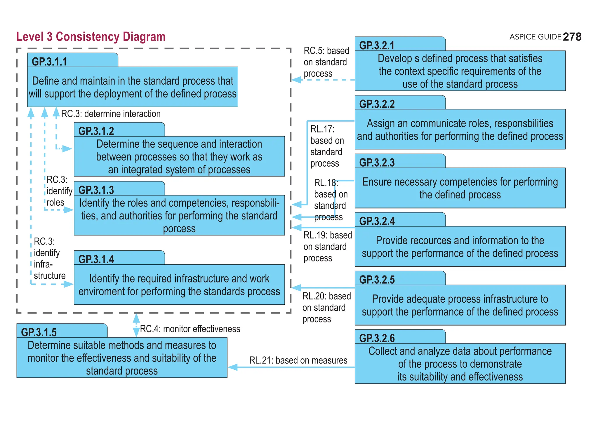
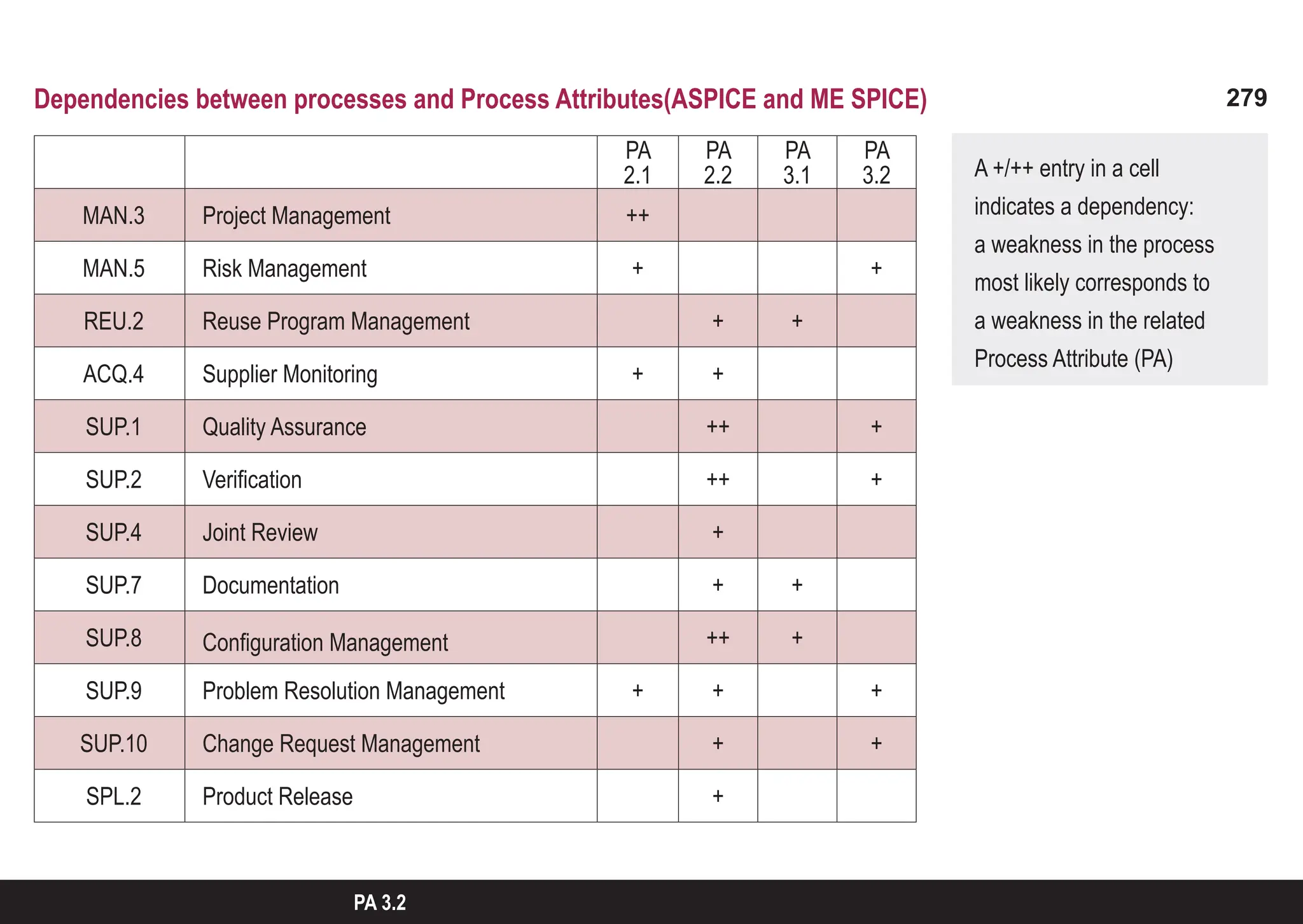
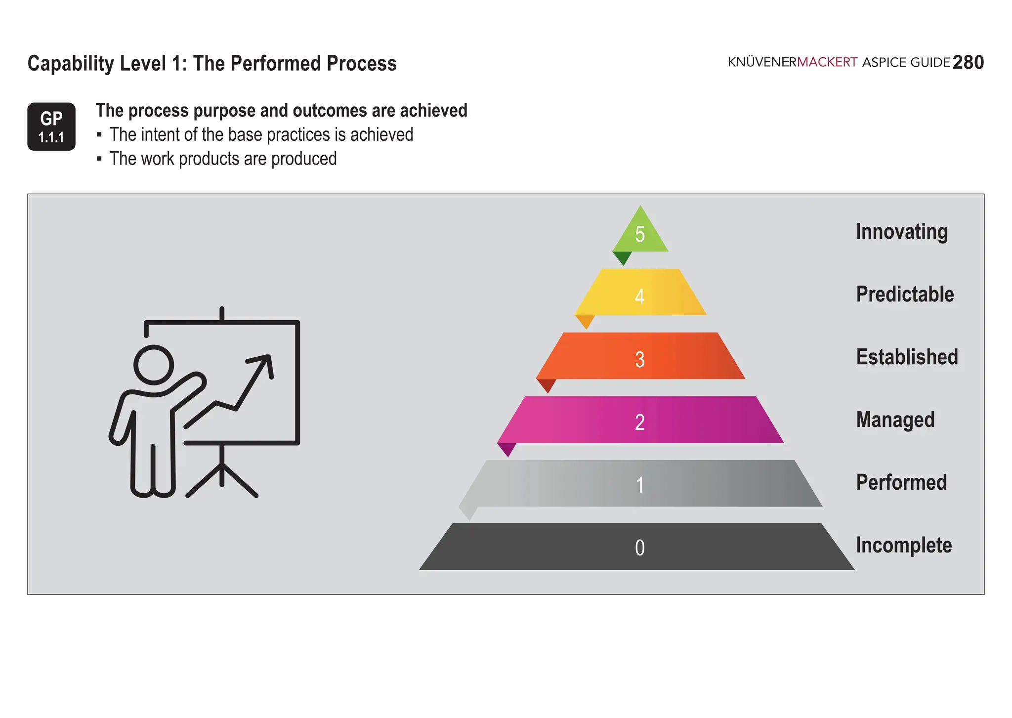
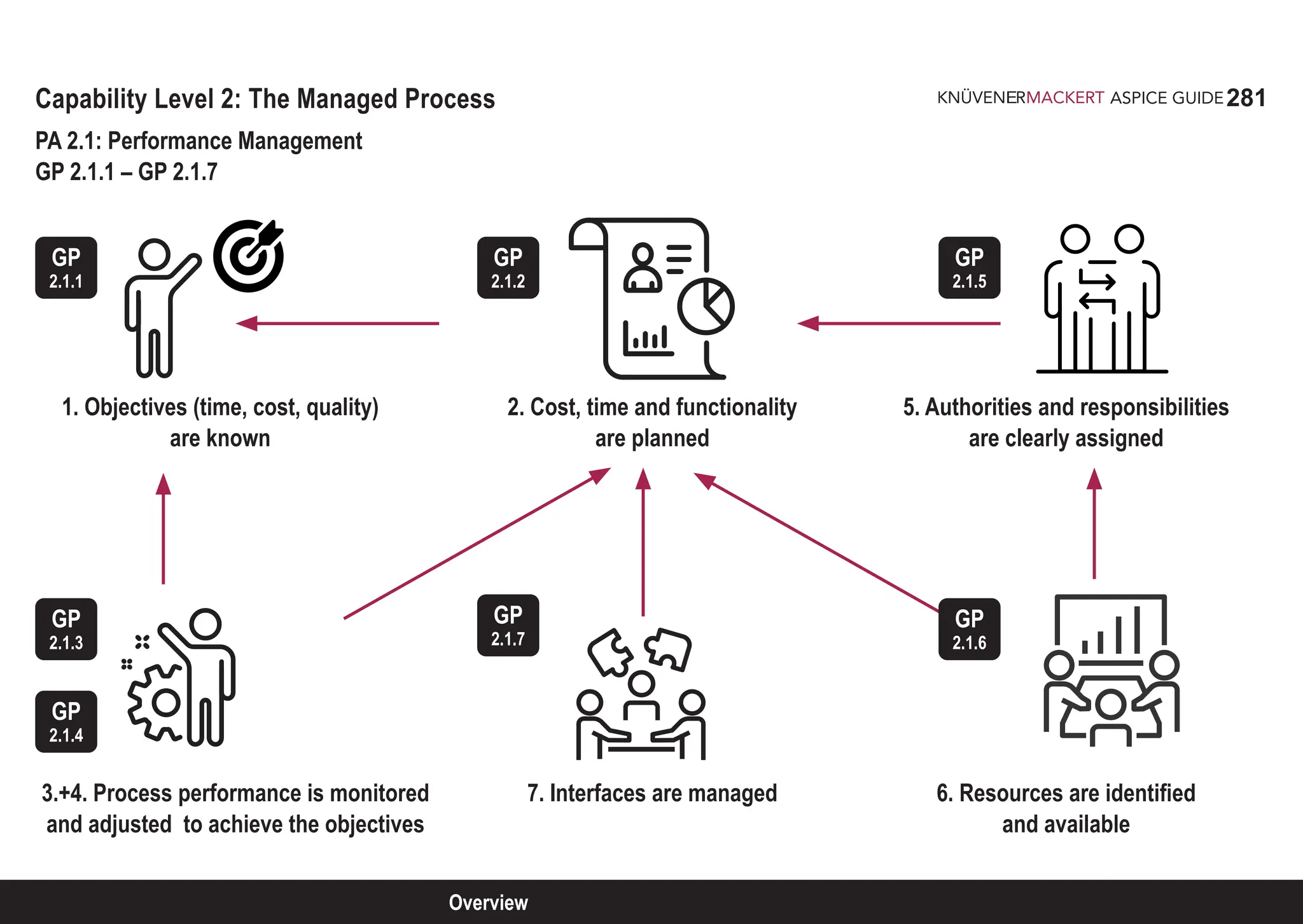
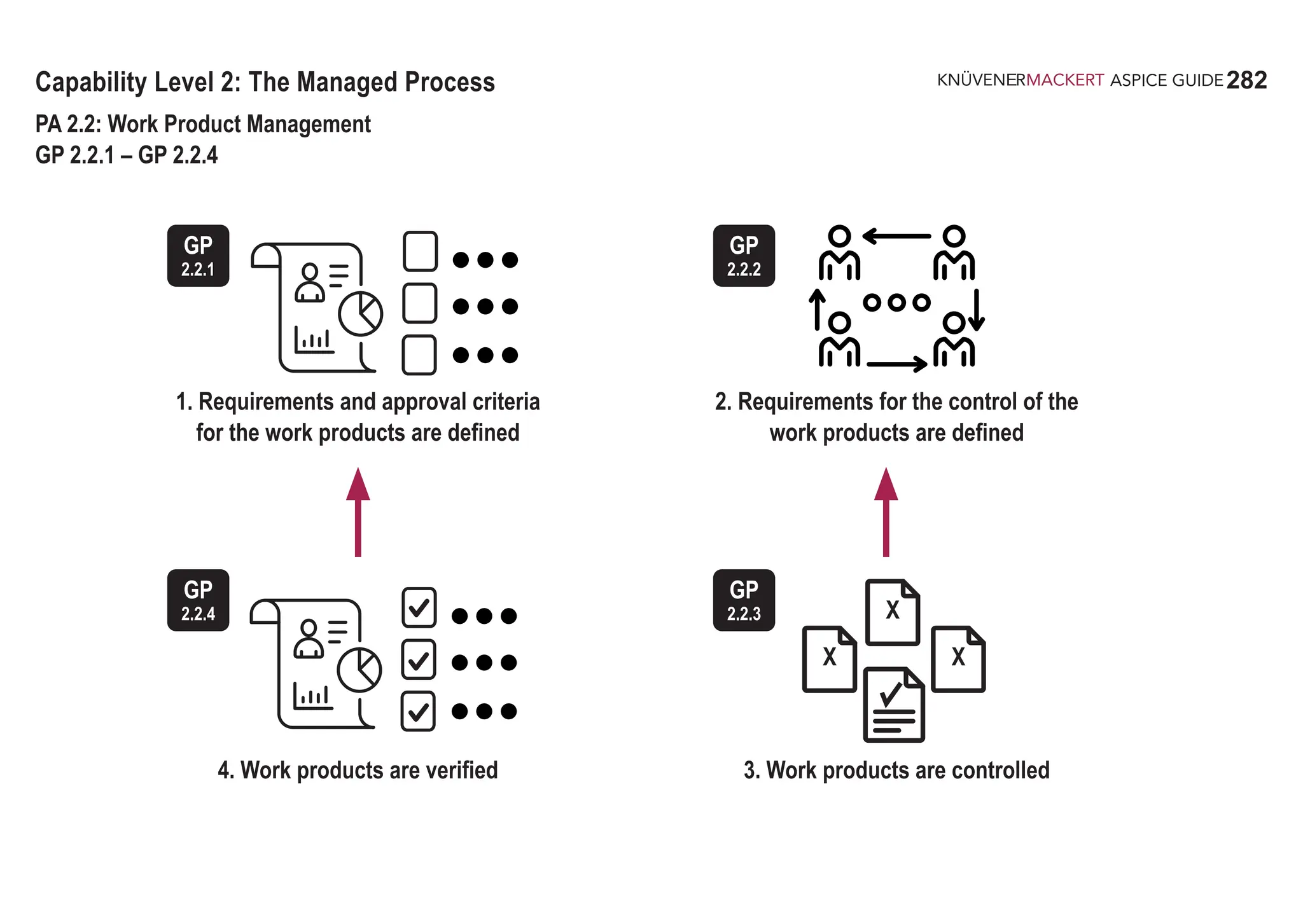
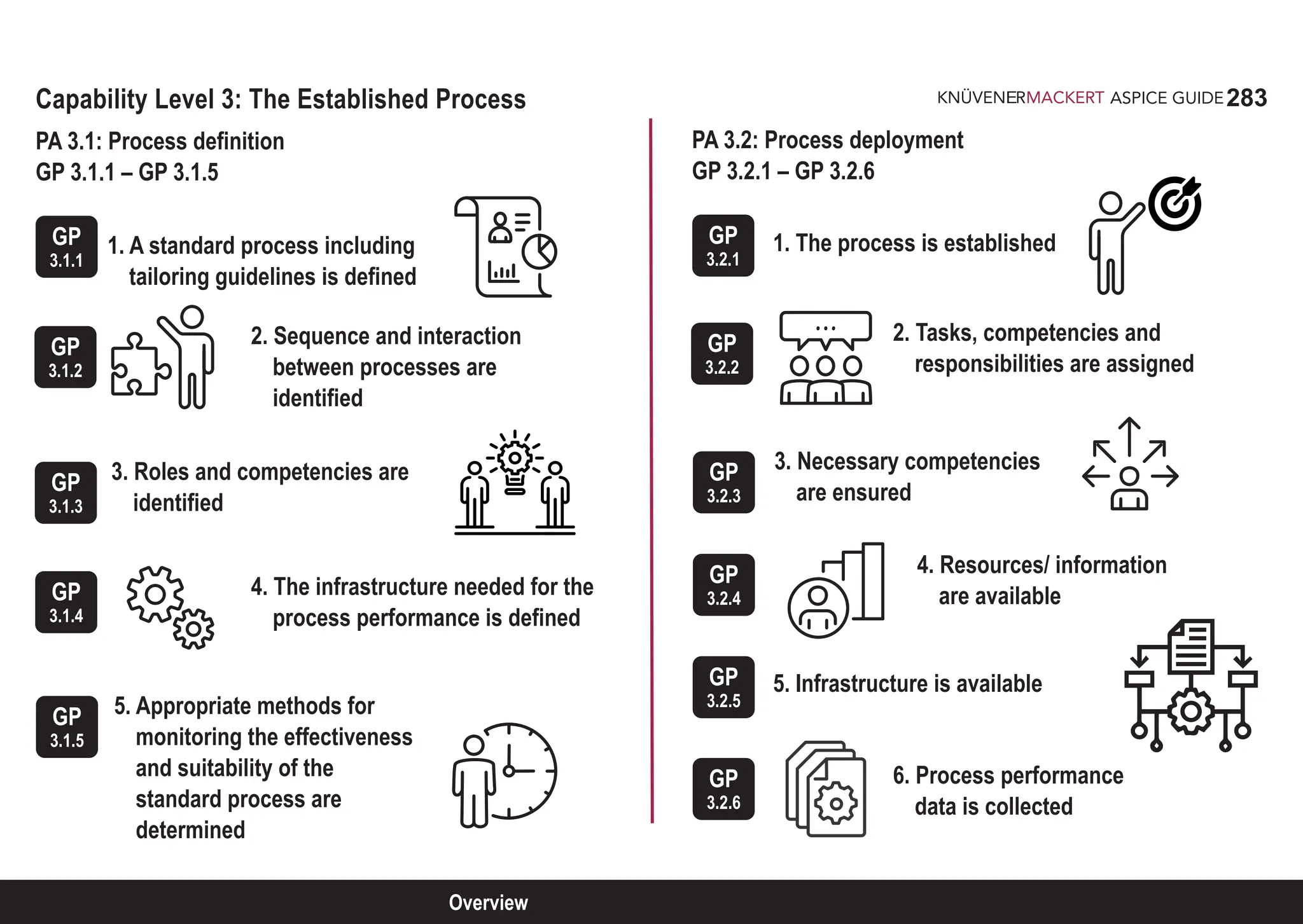
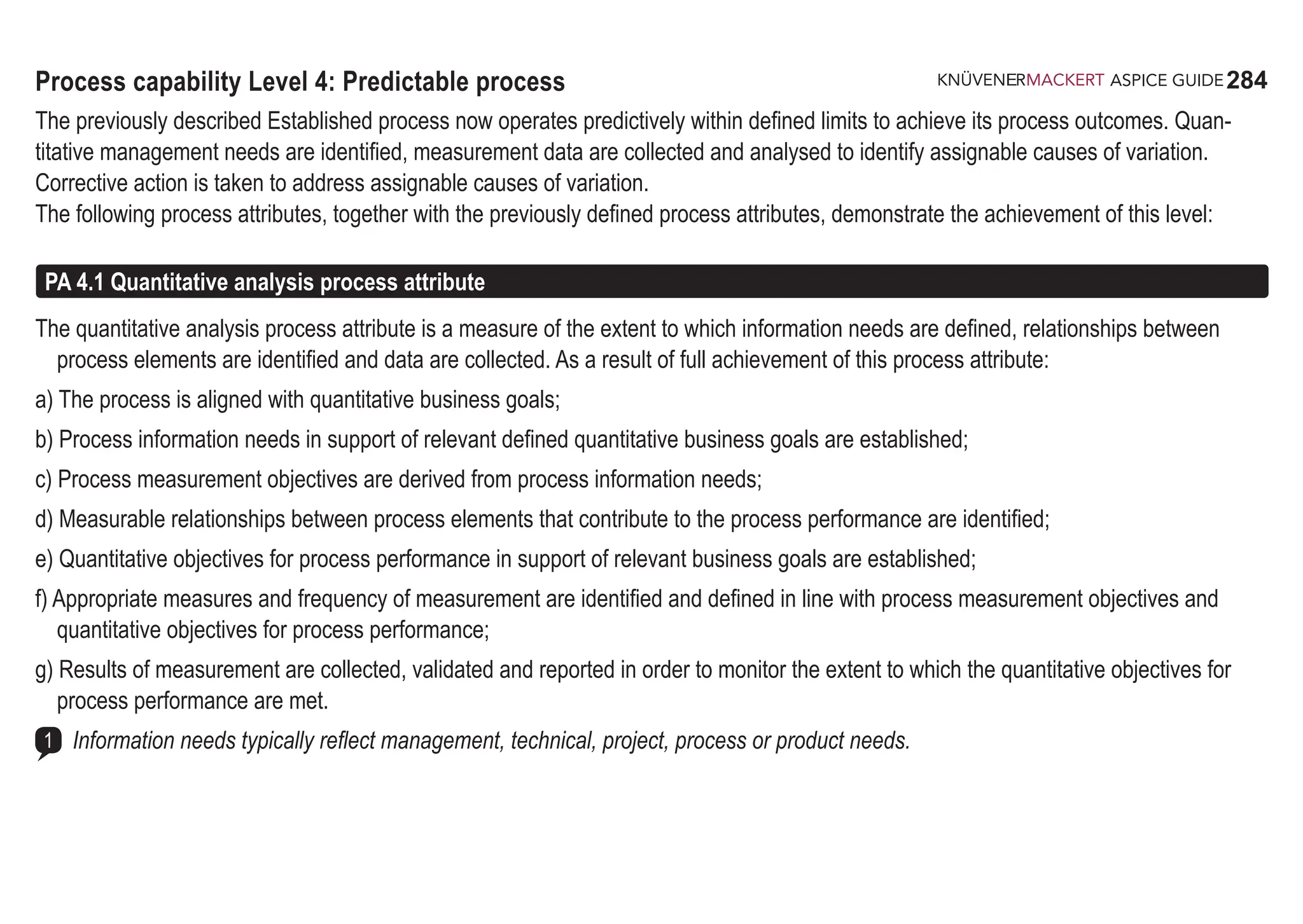
![285
ASPICE GUIDE
GP
4.1.1
Generic practices 4.1.1 - 4.1.6
Identify business goals. [ACHIEVEMENT a]
Business goals are identified that are supported by the quantitatively measured process.
Establish process information needs. [ACHIEVEMENT a, b ]
Stakeholders of the identified business goals and the quantitatively measured process, and their information needs
are identified, defined and agreed.
Derive process measurement objectives from process information needs. [ACHIEVEMENT a, c]
The process measurement objectives to satisfy the established process information needs are derived.
Identify measurable relationships between process elements. [ACHIEVEMENT a, d]
Identify the relationships between process elements, which contribute to the derived measurement objectives.
Establish quantitative objectives. [ACHIEVEMENT a, e]
Establish quantitative objectives for the identified measurable process elements and their relationships. Agreement
with process stakeholders is established.
Identify process measures that support the achievement of the quantitative objectives. [ACHIEVEMENT a, f]
Detailed measures are defined to support monitoring, analysis and verification needs of the quantitative objectives.
Frequency of data collection is defined.
Algorithms and methods to create derived measurement results from base measures are defined, as appropriate.
Verification mechanism for base and derived measures is defined.
Typically, the standard process definition is extended to include the collection of data for process measurement.
GP
4.1.2
GP
4.1.3
GP
4.1.4
GP
4.1.5
GP
4.1.6
1
285
PA 4.1](https://image.slidesharecdn.com/aspice-guide-km2021-04-240204182441-58722c47/75/ASPICE-Guide-KM2021-04-pdf-285-2048.jpg)
![286
ASPICE GUIDE
GP
4.1.7
Generic practices 4.1.7
Collect product and process measurement results through performing the defined process. [ACHIEVEMENT a, g ]
Data collection mechanism is created for all identified measures.
Required data is collected within the defined frequency, and recorded.
Measurement results are analyzed, and reported to the identified stakeholders.
A product measure can contribute to a process measure, e.g. the productivity of testing characterized by the number
of defects found in a given timeframe in relation to the product defect rate in the field.
2
286](https://image.slidesharecdn.com/aspice-guide-km2021-04-240204182441-58722c47/75/ASPICE-Guide-KM2021-04-pdf-286-2048.jpg)
![287
ASPICE GUIDE
PA 4.2 Quantitative control process attribute
The quantitative control process attribute is a measure of the extent to which objective data are used to manage process performance
that is predictable. As a result of full achievement of this process attribute:
a) Techniques for analyzing the collected data are selected;
b) Assignable causes of process variation are determined through analysis of the collected data;
c) Distributions that characterize the performance of the process are established;
d) Corrective actions are taken to address assignable causes of variation;
e) Separate distributions are established (as necessary) for analyzing the process under the influence of assignable causes of variation.
GP
4.2.1
Select analysis techniques. [ACHIEVEMENT a]
Analysis methods and techniques for control of the process measurements are defined.
Establish distributions that characterize the process performance. [ACHIEVEMENT c]
Expected distributions and corresponding control limits for measurement results are defined.
Determine assignable causes of process variation. [ACHIEVEMENT b]
Each deviation from the defined control limits is identified and recorded.
Determine assignable causes of these deviations by analyzing collected data using the defined analysis techniques.
All deviations and assigned causes are recorded.
GP
4.2.2
GP
4.2.3
287
PA 4.2
Generic practices 4.2.1 - 4.2.3](https://image.slidesharecdn.com/aspice-guide-km2021-04-240204182441-58722c47/75/ASPICE-Guide-KM2021-04-pdf-287-2048.jpg)
![288
ASPICE GUIDE
Identify and implement corrective actions to address assignable causes. [ACHIEVEMENT d]
Corrective actions are determined, recorded, and implemented to address assignable causes of variation.
Corrective action results are monitored and evaluated to determine their effectiveness.
Establish separate distributions for analyzing the process [ACHIEVEMENT e]
Separate distributions are used to quantitatively understand the variation of process performance under the influence of
assignable causes.
Generic practices 4.2.4 - 4.2.5
GP
4.2.4
GP
4.2.5
288](https://image.slidesharecdn.com/aspice-guide-km2021-04-240204182441-58722c47/75/ASPICE-Guide-KM2021-04-pdf-288-2048.jpg)
![289
ASPICE GUIDE
Process capability Level 5: Innovating process
The previously described Predictable process is now continually improved to respond to change aligned with organizational goals.
The following process attributes, together with the previously defined process attributes, demonstrate the achievement of this level:
PA 5.1 Process innovation process attribute
The process innovation process attribute is a measure of the extent to which changes to the process are identified from investigations of
innovative approaches to the definition and deployment of the process. As a result of full achievement of this process attribute:
a) Process innovation objectives are defined that support the relevant business goals;
b) Appropriate data are analysed to identify opportunities for innovation;
c) Innovation opportunities derived from new technologies and process concepts are identified;
d) An implementation strategy is established to achieve the process innovation objectives.
GP
5.1.1
GP
5.1.2
Define the process innovation objectives for the process that support the relevant business goals. [ACHIEVEMENT a]
New business visions and goals are analyzed to give guidance for new process objectives and potential areas of process
innovation.
Analyze data of the process to identify opportunities for innovation. [ACHIEVEMENT b]
Common causes of variation in process performance are identified and analyzed to get a quantitative understanding of their
impact.Identify opportunities for innovation based on the quantitative understanding of the analyzed data.
PA 5.1
Generic practices 5.1.1 - 5.1.2](https://image.slidesharecdn.com/aspice-guide-km2021-04-240204182441-58722c47/75/ASPICE-Guide-KM2021-04-pdf-289-2048.jpg)
![290
ASPICE GUIDE
Generic practices 5.1.3 - 5.1.4
GP
5.1.4
290
GP
5.1.3
Analyze new technologies and process concepts to identify opportunities for innovation. [ACHIEVEMENT c]
Industry best practices, new technologies and process concepts are identified and evaluated.Feedback on opportunities for
innovation is actively sought.Emergent risks are considered in evaluating improvement opportunities.
Define and maintain an implementation strategy based on innovation vision and objectives. [ACHIEVEMENT d]
Commitment to innovation is demonstrated by organizational management including the process owner(s) and other relevant
stakeholders.
Define and maintain an implementation strategy to achieve identified opportunities for innovation and objectives.
Based on implementation strategy process changes are planned, prioritized based on their impact on defined innovations.
Measures that validate the results of process changes are defined to determine the expected effectiveness of the process
changes and the expected impact on defined business objectives.](https://image.slidesharecdn.com/aspice-guide-km2021-04-240204182441-58722c47/75/ASPICE-Guide-KM2021-04-pdf-290-2048.jpg)
![291
ASPICE GUIDE
PA 5.2 Process innovation implementation process attribute
The process innovation process implementation attribute is a measure of the extent to which changes to the definition, management
and performance of the process achieves the relevant process innovation objectives. As a result of full achievement of this process
attribute:
a) Impact of all proposed changes is assessed against the objectives of the defined process and standard process;
b) Implementation of all agreed changes is managed to ensure that any disruption to the process performance is understood and
acted upon;
c) Effectiveness of process change on the basis of actual performance is evaluated against the defined product requirements and
process objectives.
GP
5.2.1
GP
5.2.2
Assess the impact of each proposed change against the objectives of the defined and standard process.
[ACHIEVEMENT a] New business visions and goals are analyzed to give guidance for new process objectives and potential
areas of process innovation. Objective priorities for process innovation are established. Specified changes are assessed
against product quality and process performance requirements and goals. Impact of changes to other defined and standard
processes is considered.
Manage the implementation of agreed changes. [ACHIEVEMENT b]
A mechanism is established for incorporating accepted changes into the defined and standard process(es) effectively and
completely.
The factors that impact the effectiveness and full deployment of the process change are identified and managed, such as:
• Economic factors (productivity, profit, growth, efficiency, quality, competition, resources, and capacity );
• Human factors (job satisfaction, motivation, morale, conflict/cohesion, goal consensus, participation, training, span of control);
• Management factors (skills, commitment, leadership, knowledge, ability, organizational culture and risks);
291
PA 5.2
Generic practices 5.2.1 - 5.2.2](https://image.slidesharecdn.com/aspice-guide-km2021-04-240204182441-58722c47/75/ASPICE-Guide-KM2021-04-pdf-291-2048.jpg)
![292
ASPICE GUIDE
GP
5.2.3
GP
5.2.2
• Technology factors (sophistication of system, technical expertise, development methodology, need of new technologies)
Training is provided to users of the process.
Process changes are effectively communicated to all affected parties.
Records of the change implementation are maintained.
Evaluate the effectiveness of process change. [ACHIEVEMENT c]
Performance and capability of the changed process are measured and evaluated against process objectives and historical
data. A mechanism is available for documenting and reporting analysis results to management and owners of standard and
defined process. Measures are analyzed to determine whether the process performance has improved with respect to com-
mon causes of variations. Other feedback is recorded, such as opportunities for further innovation of the predictable process.
Generic practices 5.2.2 - 5.2.3 292](https://image.slidesharecdn.com/aspice-guide-km2021-04-240204182441-58722c47/75/ASPICE-Guide-KM2021-04-pdf-292-2048.jpg)