Download to read offline
![2
yp Contribution of the fluctuating dilatation in
compressible turbulence to the overall dissipation
rate
μt0 Turbulent viscosity calculated without the swirl
modification
Ω Swirl number
αs Swirl constant value which can be selected on the
basis of swirl intensity ranging from moderate to
high value
INTRODUCTION
A high-pressure fluid (motive fluid) with very low
velocity at the primary inlet is accelerated to high velocity
jet through a converging nozzle for the liquid jet pump. A
wide range of investigations are carried out globally to
develop energy efficient desalination techniques that
induce negligible environmental pollution. Vacuum inside
the desalination system was to be achieved using the
designed two phase jet pump .Since the two-phase jet
pump is the heart of the system, the present numerical
approach helps to analyse and optimize the jet pump with
the effect of swirl in primary stream inside nozzle and how
it affects the downstream flow. Many authors have
conducted the studies on various evolutionary designs of
ejectors several years ago. The application of the liquid jet
gas pump for air and vapour removal from steam
condensers and pump casings was reported in various
German and Russian papers, beginning with Hoefer [1].
Several investigators later proposed various enhancement
in existing ejectors for getting better performance. Design
analysis of pumps that uses liquids of low viscosity have
been studied by Gosline and O’Brien [2]. Their studies
promote self entrainment of viscous fluids and two
component entrainment when the two fluids are liquids of
different densities.
Many researchers extended the work of these
pioneers contributing their own suggestions and also
carried out valuable experiments to determine the
conditions at which improvements can be achieved.
Martinelli [3] et al. reported that increase in secondary air
can be achieved by increasing pressure of fluid at primary
side. Muller [4] whereas performed studies in existing
designs and concluded that performance can be enhanced
by 37% which was reportedly the maximum efficiency. He
concluded that when the setback distance i.e, the distance
between nozzle exit and mixing chamber entry length is
equal to driving nozzle diameter and also the least angle of
the diffuser will help in enhancing efficiency of jet pump.
Pfliedderer [5] proposed that the pressure ratio
and air flow rate are independent of each other. Stepanoff
analyzed various jet pumps models and proposed a jet
centrifugal pump system. There were studies on ejectors
with multi hole nozzle . Gopichand [6] confirmed that
single nozzle is better than multiple nozzle. Experimental
investigation on various ejector geometries is carried out
by Havelka et al. [7] carried out experimental studies with
various designs of ejctorsat different operating conditions.
There were already various suggestions available in nozzle
profiles and one of those studies confirmed that elliptical
nozzle can be proved to be better by Gutmark and
Grinstein [8] for better mixing of two streams and fanning.
Similar studies were done by Sudevan [9] employing a
multi hole nozzle to optimize mixing tube length as it has
also played a major role in ejector performance. Later,
Vishnu [10] did studies on elliptical nozzle along with
conical and circular to compare the performance in his
work experimentally. The geometrical design is inspired
from his work Vishnu experiment. It was concluded that
area ratio has major role to play in ejector efficiency than
any other parameter. Reddy and Kar [11] studied the effect
of flow ratio and concluded that if it is equal to unity then
maximum efficiency of system can be achieved. Lesser
area ratio ejectors were also studied by Sangar [12] with
primary fluid as water. Winoto et al. [13] performed one
dimensional theoretical study on water- air ejector system.
Also to support his studies, he carried out experimental
work on water jet pump. And concluded that a nozzle with
non circular cross section has an impact on nozzle
performance and sharp edges may lower overall efficiency
of jet pump. Narabayashi et al. [14] did experiments as
well as and performed computational fluid dynamics
(CFD) analysis of flow in single and multi-hole nozzle jet
pumps and reported that single hole nozzle works
efficiently for zero set back distance . Also they tried a
different mixing tube with a tapered shape rather than a
traditional straight for enhancing efficiency. According to
their experimental results, five hole nozzle gives performs
ill as compared to single nozzle as in between the nozzle
finger there is more resistance developed. Gresho [15]
numerically optimized mixing throat length for area ratio
of 0.6 by three-dimensional (3-D) using re-normalization
group k-ɛ1 turbulent model. In present time, investigators
and research are attracted towards the swirl activity in
nozzle such studies were carried out by Guillaume and
Judge [16] through their experiments. They reported that at
moderate swirl, the jet pump has shown 4.5% increment in
entrained secondary fluid which leads to 5% increase in
overall efficiency when compared to the same pump
without swirl . Samad et al. [17] and shows that swirl
promotes jet breakup resulting in higher suction rates. He
incorporates swirler of various angle in his experiments.
Although various combination of design prove that
incorporating swirl into a jet pump may increase
performance, Zhou et al. [18], showed numerically that
swirl can be detrimental to pump performance.
Specifically, they used commercial CFD software
FLUENT to model the effect of swirling the primary jet in
a study designed to evaluate the effectiveness of a jet pump
on reducing the infrared signature of the exhaust of a gas
turbine. They found numerically that pump performance
decreased as the swirl angle was increased.](https://image.slidesharecdn.com/ddb93a4d-0a02-4d15-8c77-9d7c6efd7037-150826104259-lva1-app6891/75/Arpita_ISHMT2015-2-2048.jpg)
![3
CFD ANALYSIS OF EJECTOR
The efficiency of the pump can be calculated by using the
flow ratio and head ratio as
(1)
(2)
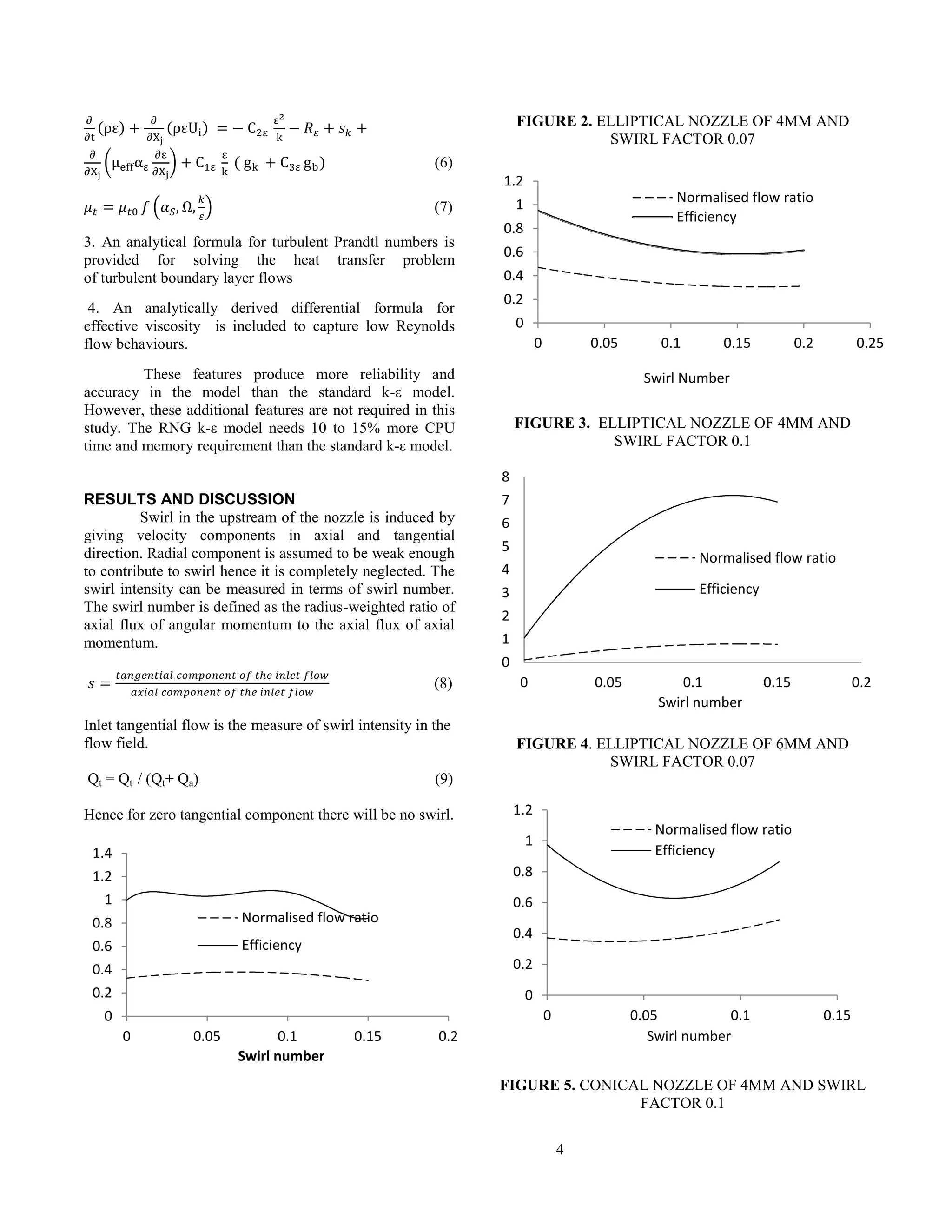
FIGURE 1. REPRESENTATIONAL VIEW OF
EJECTOR OF JET PUMP
The traditional view of ejector is shown in Figure 1.
Further in current study the profile of nozzle will be
changed to visualise change in flow pattern. The
dimensions of ejector used are shown in Table 1 [10].
In the present study, the CFD software ANSYS Fluent
14.0 has been employed to analyze a two-phase ejector of
jet pump which is supposed to be part of an experimental
set up. It is designed to entrain air from a pressure vessel to
create vaccum. Considering the situation to be an
incompressible, steady flow, the axisymmetric pressure-
based solver has been used. The governing equations for
mass and momentum conservation are given in tensor
notation as
(3)
(4)
TABLE 1. DESIGN PARAMETERS OF NOZZLE
Notation Conical
(mm)
Elliptical
(mm)
Circular
(mm)
Do 4,6,8 4,6,8 4,6,8
Dp 21,21,25 21,21,25 21,21,25
Dmt 10 10 10
Dsec 21 21 21
Lmt 265 265 265
S 20 20 20
Ld 135 135 135
Dd 21 21 21
2°30’ 2°30’ 2°30’
The pressure drop that takes place at various pipe
connections has been neglected. The solver is appropriate
for both lower as well as higher values of Reynolds
number and is applicable for simulating the two-phase flow
of air-water mixture. Pressure velocity coupling offers to
solve the problem in either segregated manner or coupled
manner. The SIMPLE algorithm is followed which solves
equations of velocity and pressure to enforce mass
conservation and to obtain the pressure field. Also, this
solver takes lesser computational time and memory. Spatial
Discretization scheme contains settings that control the
spatial discretization of the convection terms in the
solution equations and here for calculating gradients Least
Squares Cell-Based is used. Standard scheme is taken for
pressure, power law scheme for momentum, swirl velocity,
kinetic energy and turbulent dissipation rate and first order
upwind for volume fraction. The standard interpolation
schemes for calculating cell-face pressures takes lesser
time as compared to power law method. For bubble flow
there are Mixture model and Eulerian model can be used to
solve multiphase flow. Mixture model is based on pressure
solver. The differences in between both is that the mixture
model can be a substitute for the full Eulerian multiphase
model in some cases. A full multiphase model is not as
feasible as mixture model. The under relaxation factor for
pressure and momentum quatities are kept as 0.3 and for
the turbulent quantities 0.6. The solutions were assumed to
have converged for the residual level of 10-4
for continuity,
x-velocity, and y velocity and 10-6
for k -epsilon. For
selecting the turbulent model, one can think of standard k-ε
model which is considered as the simplest “complete
model” of turbulence. It is a model based on model
transport equations for the turbulence kinetic energy (k)
and its dissipation rate (ε), that means, it includes two extra
transport equations to represent the turbulent properties of
the flow. Renormalization-Group (RNG) model is
improved from the standard k-ε model by using a rigorous
statistical technique. It is similar to the standard k-ε model,
but can be proved more beneficial as compared to standard
or realizable k-ε model.
1. It includes extra term in governing equation that
provides better accuracy for rapidly strained flows.
2. The effect of swirl in the form of swirl factor is included
which can be activated for swirl dominated flow condition,
and hence improves the accuracy for swirling and rotating
flows. For strongly swirling flows, however, a higher value
of swirl factor can be used which is st as 0.07 for moderate
swirl by default in the software.
Transport Equations for the RNG k- ε Model
–
(5)](https://image.slidesharecdn.com/ddb93a4d-0a02-4d15-8c77-9d7c6efd7037-150826104259-lva1-app6891/75/Arpita_ISHMT2015-3-2048.jpg)
![5
FIGURE 6. CONICAL NOZZLE OF 4MM AND USING
REALIZABLE
K-Ɛ MODEL
The concept of normalized–flow ratio K was given by
Guillaume and Judge [16]. It compares the performance of
jet pump with and without inclusion of swirl and hence is
one of the performance parameter for determining pump
efficiency.
without swirl
with swirl
/
/
S P
S P
Q Q
K
Q Q
(10)
Since QP is same for both cases, hence
, with swirl
, without swirl
S
S
Q
K
Q
(11)
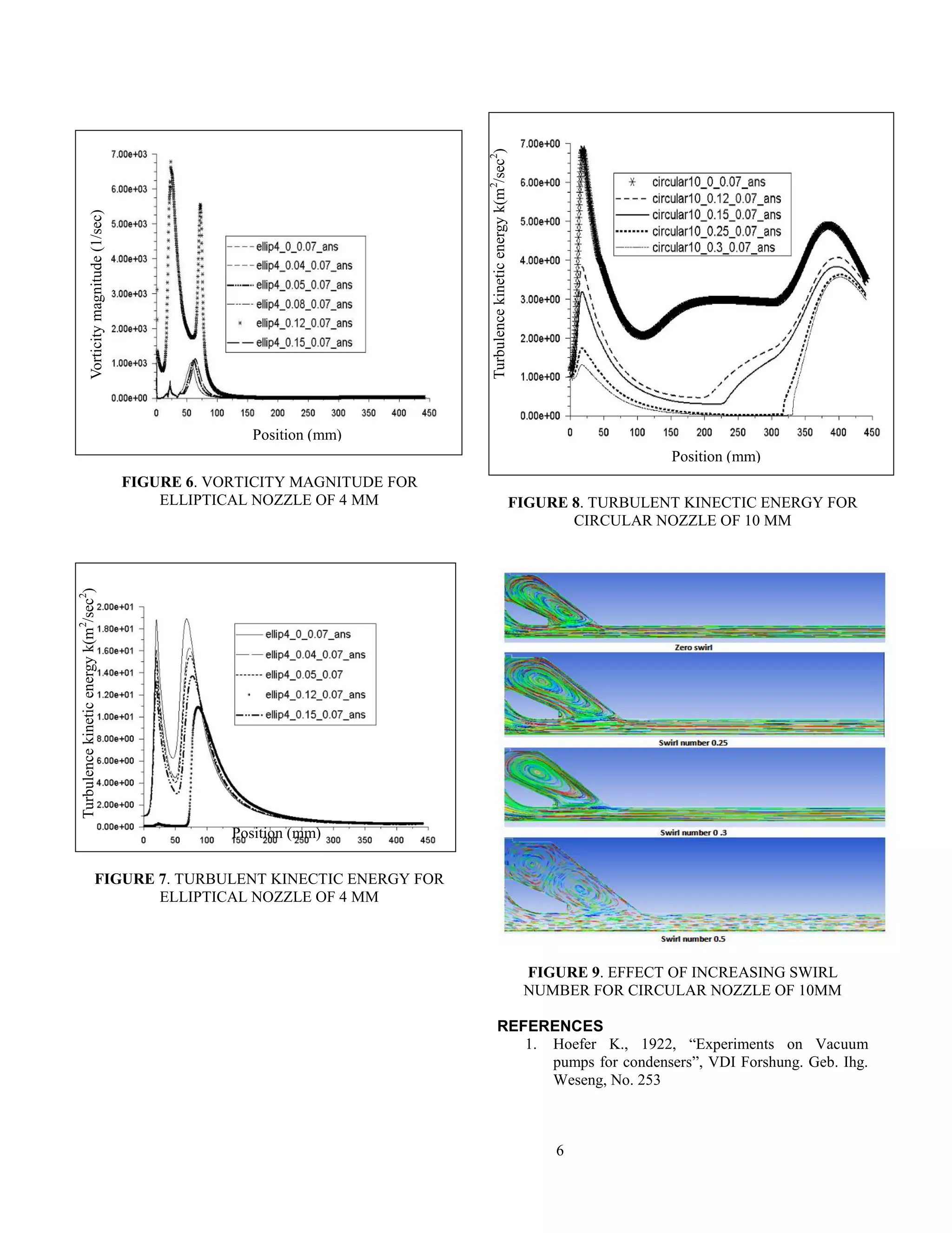
Figure 2 shows the variation of efficiency and normalized
flow ratio with respect to swirl number in elliptical profiled
nozzle. Initially, the secondary flow decreases but on
giving 9% of axial flow as the inlet tangential flow it
reaches it maximum and further start decreasing. As shown
in Figure 3, on increasing the swirl factor, for the same
cases, from default 0.07 value to 0.1, the secondary
entrainment as well as efficiency of jet pump decreases.
Similar trends were observed in other nozzles also.
Performance curves obtained on employing different
model can be seen in Figure 5 and Figure 6 for conical
nozzle of 4mm throat diameter. An increase in swirl
number can cause a increase in entrainment but further
increase in swirl will cause a depreciation too. This can be
observed from Table 2 where on increasing the tangential
component of flow there is increase in secondary flow but
as swirl intensity is raised by giving swirl factor as 0.1 is
went down. Figure 9 shows a comparative view of flow
pattern on increasing the swirl number. On giving swirl
number upto 0.25 to 0.3 there is an increase in entrainment
and then decreases further causing reverse flow in the
secondary. On observing the Figure 6 similar trend is
observed. For swirl number 0.12 it attains maximum and a
maximum entrainment is thus reported. The vortices
developed enhances the secondary flow and enable better
mixing of fluids. However, turbulent kinetic energy
however decreases on attaining higher swirl number as
shown in Figure 7-8 . A decreasing turbulent intensity does
signifies that the flow becomes less turbulent. It can be
predicted that the velocity fluctuations divided by the
mean velocity decreases. If both values increases, but the
mean velocity increases even more, than the intensity
decreases. Reynolds number is a ratio representing the
relative importance of inertial forces to viscous forces in
the flow. Further wall effects can be studied to get more
realistic view of the flow. This preliminary experiment
shows that the efficiency of a jet pump can be significantly
improved by simply replacing the jet nozzle that has a
round cross section with a jet nozzle that has an elliptical
cross section.
CONCLUSION
It was found that elliptical nozzle with 4mm diameter gives
better efficiency as compared to other nozzle for the same
inlet flow condition. The formation of vortices and their
interaction with walls also plays an important role in
determining entrainment as it influence the mixing of two
phase fluids at downstream. Upon giving 10% to 12% of
axial flow as a tangential flow at the inlet there is a
increase in entrainment by 4 to 7 %. Further based on the
swirl numbers leading to better efficiency swirler can be
designed to validate the results.
FIGURE 5. VELOCITY PROFILE FOR ELLIPTICAL
NOZZLE OF 4 MM
0
0.2
0.4
0.6
0.8
1
1.2
1.4
1.6
1.8
0 0.02 0.04 0.06 0.08 0.1 0.12
Swirl number
Efficiency
----- Normalised flow ratio
Position (mm)
VelocityMagnitude(m/sec)](https://image.slidesharecdn.com/ddb93a4d-0a02-4d15-8c77-9d7c6efd7037-150826104259-lva1-app6891/75/Arpita_ISHMT2015-5-2048.jpg)

1. The document summarizes a numerical investigation of a two-phase jet pump with and without a swirling primary jet. 2. The study models different nozzle profiles, including circular, elliptical, and conical shapes, to analyze how swirling the primary jet affects pump performance characteristics like efficiency. 3. The results show that introducing a moderate amount of swirl can increase the secondary fluid entrainment and overall efficiency, but higher swirl intensities decrease performance. The optimal swirl depends on factors like the nozzle diameter and shape.


