Downloaded 178 times


![ARIHANT PRAKASHAN (Series), MEERUT
[B.Tech, M.Tech, Pantnagar, ID 15722]
DC Pandey
NEET
PHYSICS
OBJECTIVE
Volume02](https://image.slidesharecdn.com/arihantneetobjectivephysicsvolume2bydcpandey2022edition-230417145135-9bce7664/85/Arihant_NEET_Objective_Physics_Volume_2_By_DC_Pandey_2022_Edition-pdf-3-320.jpg)


![ELECTRIC CHARGES
Electric charge can be defined as an intrinsic property of elementary particles of
matter which give rise to electric force between various objects. It is represented
by q. The SI unit of electric charge is coulomb (C). A proton has positive charge
( )
+e and an electron has negative charge (−e), where e = × −
1.6 10 C
19
.
Important points regarding electric charge
The following points regarding electric charge are worthnoting
(i) Like charges repel each other and unlike charges attract each other.
(ii) The property which differentiates two kinds of charge is called the polarity
of charge. If an object possesses an electric charge, then it is said to be
electrified or charged. When its net charge is zero, then it is said to be
neutral (just like neutron).
(iii) Charge is a scalar quantity as it has magnitude but no direction. It can be of
two types as positive and negative. When some electrons are removed from
the atom, it acquires a positive charge and when some electrons are added
to the atom, it acquires a negative charge.
(iv) Charge can be transferred from one body to another.
(v) Charge is invariant, i.e. it does not depend on the velocity of charged
particle.
(vi) A charged particle at rest produces electric field. A charged particle with
unaccelerated motion produces both electric and magnetic fields but does not
radiate energy. But an accelerated charged particle not only produces an
electric and magnetic fields but also radiates energy in the form of
electromagnetic waves.
(vii) 1 coulomb = ×
3 109
esu =
1
10
emu of charge, where esu is electrostatic unit
of charge. Its CGS unit is stat coulomb.
(viii) The dimensional formula of charge is [ ] AT
q = [ ].
01
Electric Charges
and Fields
CHAPTER
Inside
1
2
3
Electric charges
Coulomb’s law
Electric field
Conductors and insulators
Force between multiple charges
(Superposition principle)
Applications of electric force
(Coulomb’s law)
Applications of Gauss’s law
Electric dipole
Methods of charging
Electric field lines
Continuous charge distribution
Electric field of a charged ring
Electric flux
Gauss’s law
The field of an electric dipole
or dipole field
Torque on an electric dipole
Force on dipole
Work done in rotating a dipole
in a uniform electric field
4
5](https://image.slidesharecdn.com/arihantneetobjectivephysicsvolume2bydcpandey2022edition-230417145135-9bce7664/85/Arihant_NEET_Objective_Physics_Volume_2_By_DC_Pandey_2022_Edition-pdf-12-320.jpg)
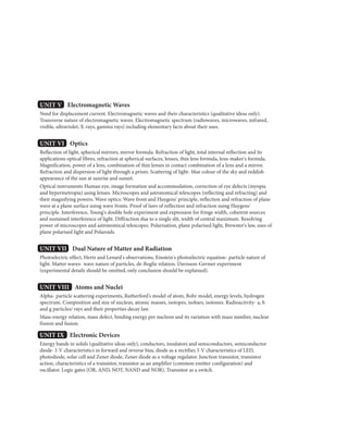
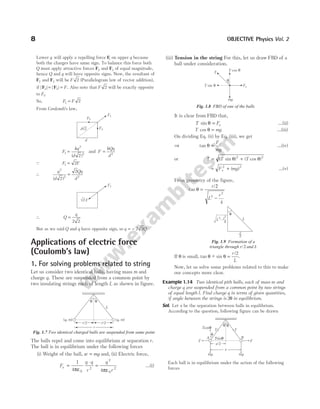
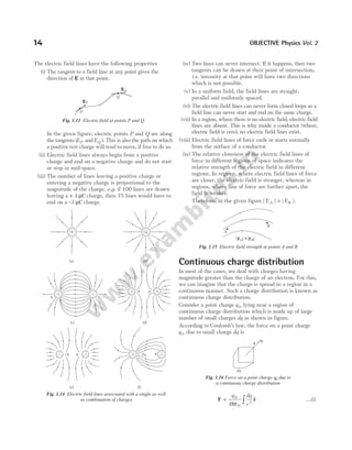
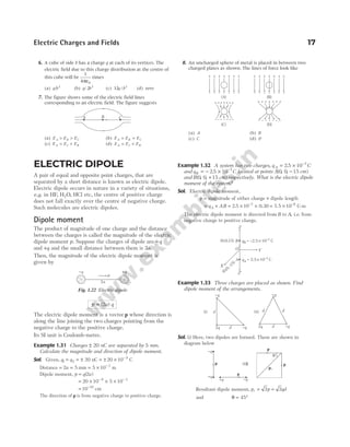
![Force between multiple charges
(Superposition principle)
According to the principle of superposition, ‘‘total force on
a given charge due to number of charges is the vector sum
of individual forces acting on that charge due to all the
charges’’. The individual forces are unaffected due to the
presence of other charges.
Suppose a system contains n point charges q1, q 2,K, qn .
Then, by the principle of superposition, the force on q1
due to all the other charges is given by
F F F F
1 12 13 1
= + + …… + n
F
r r r
1
1
0
2 12
12
2
3 13
13
2
1
1
2
4
= + + ……
q q
r
q
r
q
r
n n
n
πε
$ $ $
=
=
q q
r
i
n
i i
i
1
0 2
1
1
2
4πε
Σ
$
r
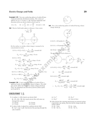
Example 1.9 Equal charges each of 20 µC are placed at
x = 0, 2, 4, 8, 16 cm on X-axis. Find the force experienced
by the charge at x = 2 cm.
Sol. Force on charge at x = 2 cm due to charge at x = 0 cm and
x = 4 cm are equal and opposite, so they cancel each other.
Net force on charge at x = 2 cm is resultant of repulsive forces
due to two charges at x = 8 cm and x = 16 cm.
∴ F
q q
=
×
−
+
−
1 2
0
2 2
4
1
0 08 0 02
1
016 0 02
πε ( . . ) ( . . )
= × × +
−
9 10 20 10
1 1
014
9 6 2
2
[ ]
( . )
(0.06)2
= 1.2 ×10³
N
Example 1.10 Five point charges each of value +q are
placed on five vertices of a regular hexagon of side a metre.
What is the magnitude of the force on a point charge of
value −q coulomb placed at the centre of the hexagon?
Sol. Let the centre of the hexagon be O. When the centre is
joined with the vertices of a hexagon, then six triangles are
formed. Consider ∆ODE
a
r
/
cos
2
60
1
2
= ° =
∴ a r
=
Given, q q q q q q
1 2 3 4 5
= = = = =
Net force on −q is due to q3 because forces due to q1 and q4
are equal and opposite, so cancel each other. Similarly, forces
due to q2 and q5 also cancel each other. Hence, the net force
on −q is
F
q q
r
= ⋅
1
4 0
2
π ε
( ) ( )
(towards q3)
or F
q
a
= ⋅
1
4 0
2
2
π ε
Example 1.11 Two fixed charges +4q and +q are at a
distance 3 m apart. At what point between the charges, a
third charge +q must be placed to keep it in equilibrium?
Sol. Remember, if Q1 and Q2 are of same nature (means both
positive or both negative), then the third charge should be
placed between (not necessarily at mid-point) Q1 and Q2 on
the straight line joining them. But, if Q1 and Q2 are of opposite
nature, then the third charge will be put outside and close to
that charge which is lesser in magnitude.
Here, Q1 and Q2 are of same nature that of third charge q, so it
will be kept in between at a distance x from Q1 (as shown in
figure). Hence, q will be at a distance ( )
3 − x from Q2. Since, q
is in equilibrium, so net force on it must be zero. The forces
applied by Q1 and Q2 on q are in opposite direction, so as to
just balance their magnitudes.
Force on q by Q
kQq
x
1
1
2
= and that by Q
kQ q
x
2
2
2
3
=
−
( )
Now,
kQq
x
kQ q
x
1
2
2
2
3
=
−
( )
or
Q
x
Q
x
1
2
2
2
3
=
−
( )
or
4 1
3
2 2
x x
=
−
( )
Take the square root,
2 1
3
x x
=
−
( )
or 6 2
− =
x x (after cross multiplication) or x = 2 m. So, q will
be placed at a distance 2 m from Q1 and at 1m from Q2.
Note If q q
1 2 0
> , then
x
r
q
q
1
0
2
1
1
=
+
(x1 is distance from q1 between q1 and q2)
If q q
1 2 0
< , then
x
r
q
q
1
0
2
1
1
=
−
(x1 in this case is not between the charges)
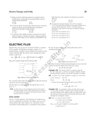
Example 1.12 Three charges q C
1 1
= µ , q C
2 2
= – µ and
q C
3 3
= µ are placed on the vertices of an equilateral
triangle of side 1.0 m. Find the net electric force acting on
charge q1.
6 OBJECTIVE Physics Vol. 2
F1n
F13
F12
q1
q2
q3
qn
Fig. 1.6 Force between the charges q q q qn
1 2 3
, , , ,
K
Aq1 B q2
E q5 Dq4
F C q3
–q
r
a
E D
O
60°
a/2
r
O
x (3 )
- x
q
Q q
1 = +4 Q q
2 = +](https://image.slidesharecdn.com/arihantneetobjectivephysicsvolume2bydcpandey2022edition-230417145135-9bce7664/85/Arihant_NEET_Objective_Physics_Volume_2_By_DC_Pandey_2022_Edition-pdf-17-320.jpg)
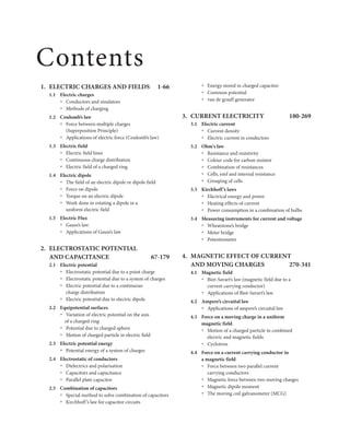
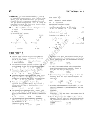
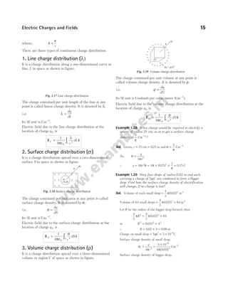
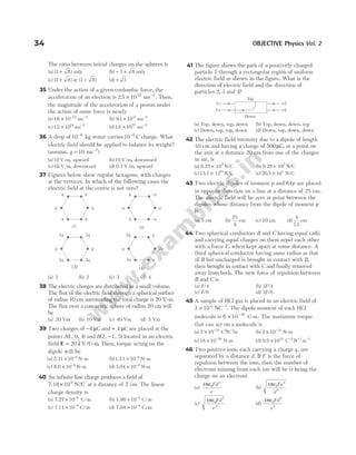
![Sol. Charge q2 will attract charge q1 (along the line joining them)
and charge q3 will repel charge q1. Therefore, two forces will
act on q1, one due to q2 and another due to q3. Since, the force
is a vector quantity both of these forces (say F
1 and F2) will be
added by vector method. Following are two methods of their
addition.
Method I. In the figure,
Magnitude of force between and
q q
1 2,
| |
F
1 1
0
1 2
2
1
4
= = ⋅
F
q q
r
πε
where, q1
6
1 1 10
= = × −
µC C
and q2 2
= = × −
µ C 2 10 C
6
.
⇒ F1 =
× × ×
− −
(9.0 10 ) (1.0 10 ) (2.0 10 )
(1.0)
9 6 6
2
= × −
1.8 10 N
2
Similarly, magnitude of force between and
1 3
q q ,
| |
F2 2
0
1 3
2
1
4
= = ⋅
F
q q
r
πε
where, q3
6
3 3 10
= = × −
µC C.
⇒ F2 =
× × ×
− −
(9.0 10 ) (1.0 10 ) (3.0 10 )
(1.0)
9 6 6
2
= × −
2.7 10 N
2
Now, net force, | | cos
F
net = + + °
F F F F
1
2
2
2
1 2
2 120
= + + −
(1.8) (2.7) 2 (1.8) (2.7)
1
2
2 2
× −
10 N
2
= × −
2.38 10 N
2
and tan
sin
cos
α =
°
+ °
F
F F
2
1 2
120
120
=
×
× + × −
−
− −
(2.7 10 ) (0.87)
(1.8 10 ) (2.7 10 )
2
2 2 1
2
or α = °
79.2
Thus, the net electric force on charge q1 is 2.38 10 N
2
× −
at an
angle α = °
79.2 with a line joining q1 and q2 as shown in the
figure.
Method II. In this method, let us assume coordinate axes
with q1 at origin as shown in figure. The coordinates of q q
1 2
,
and q3 in this coordinate system are (0, 0, 0), (1 m, 0, 0) and
(0.5 m, 0.87 m, 0), respectively. Now,
F
1 1 2
= Force on due to charge
q q
= ⋅
1
4 0
1 2
1 2
3 1 2
πε
q q
| – |
( – )
r r
r r
=
× × ×
(9.0 10 ) (1.0 10 ) (–2.0 10 )
(1.0)
9 –6 –6
3
× + +
[( – ) $ ( – ) $ ( – ) $ ]
0 1 0 0 0 0
i j k
= × −
(1.8 10 ) N
2 $
i
and F2 1 3
Force on due to charge
= q q
= ⋅
1
4 0
1 3
1 3
3 1 3
πε
q q
| – |
( – )
r r
r r
=
× × ×
(9.0 10 ) (1.0 10 ) (3.0 10 )
(1.0)
9 –6 –6
3
× − + − + −
[( $ ( ) $ ( ) $]
0 0.5 0 0.87 0 0
) i j k
= − − × −
( $ $)
1.35 2.349
i j 10 2
N
Therefore, net force on q1 is
F F F
= +
1 2
= × −
(0.45 2.349
– ) 10
$ $
i j 2
N
| | ( . ) .
F = + × = ×
− −
(0.45) N N
2 2 2 2
2 349 10 2 39 10
If the net force makes an angle α from the direction of X-axis,
then
α =
−
= − °
−
tan
.
.
.
1 2 349
0 45
79 2
Negative sign of α indicate that the net force is directed
below the X-axis.
Example 1.13 Four charges Q q Q
, , and q are kept at the
four corners of a square as shown below. What is the
relation between Q and q, so that the net force on a charge q
is zero?
Sol. Here, both the charges q will have same sign either positive
or negative. Similarly, both the charges Q will have same sign.
Let us make the force on upper right corner q equal to zero.
Electric Charges and Fields 7
q1 1 C
= µ q2 2 C
= − µ
q3 = 3 C
µ
q1 q2
q3
α
120°
F1
F2 Fnet
Q q
q Q](https://image.slidesharecdn.com/arihantneetobjectivephysicsvolume2bydcpandey2022edition-230417145135-9bce7664/85/Arihant_NEET_Objective_Physics_Volume_2_By_DC_Pandey_2022_Edition-pdf-18-320.jpg)
![(a) Weight of the ball, mg
(b) Repulsive electric force, F
q
x
=
1
4 0
2
2
π ε
(c) Tension in the string, T
Resolving T in the horizontal and vertical direction,
since ball is in equilibrium,
T F
sin θ = …(i)
T mg
cos θ = …(ii)
By Eqs. (i) and (ii), we get
tan θ =
π ε
F
mg
q
x
mg
=
1
4 0
2
2
…(iii)
Form figure,
x
l
2
= sin θ ⇒ x l
= 2 sin θ
Put value of x in Eq. (iii), we get
q mgx
2
0
2
4
= πε θ
tan
= 4 2
0
2
πε θ θ
mg l
( sin ) tan
q mgl
= [ sin tan ]/
16 0
2 2 1 2
πε θ θ
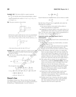
Example 1.15 Two identical balls, each having a charge q
and mass m, are suspended from a common point by two
insulating strings each of length L. The balls are held at a
separation x and then released. Find
(i) the electric force on each ball.
(ii) the component of the resultant force on a ball along and
perpendicular to string.
(iii) the tension in the string.
(iv) the acceleration of one of the balls. Consider the situation
only for the instant just after the release.
Sol. When the separation between the balls is x in equilibrium
condition, then according to question, the following figure can
be drawn
(i) Electric force between balls, F
q
x
e =
1
4 0
2
2
πε
.
(ii) Resolving forces along and perpendicular to string.
Resultant force on ball along the string,
T mg Fe
− + =
( cos sin )
θ θ 0 [the string is unstretchable]
Similarly, force perpendicular to the string
= −
| cos sin |
F mg
e θ θ
θ can be obtained from geometry.
(iii) Since, the net force on the ball along string is zero,
hence
T mg Fe
= cos sin
θ + θ
(iv) Acceleration of ball, a
F mg
m
e
=
−
| cos sin |
θ θ
Example 1.16 A particle A having charge q and mass m is
placed at the bottom of a smooth inclined plane of
inclination θ. Where should a block B, having same charge
and mass, be placed on the incline plane, so that it may
remain in equilibrium?
Sol. The following figure can be drawn in accordance with the
question
Let block B be placed at distance d. The block B is in
equilibrium. So, mg cos θ is balanced by normal reaction and
mg sin θ by repulsive electric force, i.e.
F mg
e = sin θ
⇒
1
4 0
2
2
π ε
θ
q
d
mg
= sin
⇒ d q
mg
=
1
4 0
πε θ
sin
2. Lami’s theorem
In few problems of electrostatics, Lami’s theorem is very
useful. According to this theorem, if three concurrent
forces F F
1 2
, and F3 as shown in figure are in equilibrium
or if F F F
1 2 3 0
+ + = , then
F F F
1 2 3
sin sin sin
α β γ
= =
Electric Charges and Fields 9
q
x
T
L
Fe
mg
q
Fe cos θ
mg sin θ Fe sin θ
mg cos θ
T
L2–
x2
—
4
x
—
2
L
θ
q
mg sin
q
N
mg
mg cos q
d
A q m
( , )
Fe
B
q
Fig. 1.10 Three forces passing through a point](https://image.slidesharecdn.com/arihantneetobjectivephysicsvolume2bydcpandey2022edition-230417145135-9bce7664/85/Arihant_NEET_Objective_Physics_Volume_2_By_DC_Pandey_2022_Edition-pdf-20-320.jpg)
![ELECTRIC FIELD
The region surrounding a charge or distribution of charge
in which its electrical effects can be observed or
experienced is called the electric field of the charge or
distribution of charge.
Electric field at a point can be defined in terms of either a
vector function E called electric field strength or a scalar
function V called electric potential.
Electric field strength
The electric field strength (often called electric field) at a
point is defined as the electrostatic force Fe per unit
positive test charge. Thus, if the electrostatic force
experienced by a small test charge q 0 is Fe , then field
strength at that point is defined as
E
F
=
→
lim
q
e
q
0 0 0
The electric field is a vector quantity and its direction is
the same as the direction of the electrostatic force Fe on a
positive test charge.
The SI unit of electric field is N/C. The dimensions for E
is [ ]
MLT A
− −
3 1
. For a positive charge, the electric field
will be directed radially outwards from the charge. On the
other hand, if the source charge is negative, the electric
field vector at each point is directed radially inwards.
Note Suppose there is an electric field strength E at some point, then the
electrostatic force acting on a charge +q is qE in the direction of E,
while on the charge –q it is qE in the opposite direction of E.
Example 1.18 An electric field of 105
N/C points due west
at a certain spot. What are the magnitude and direction of the
force that acts on a charge of + 2 µC and − 5 µC at this spot?
Sol. Electrostatic force, F qE
=
where, q = charge
and E = electric field.
Here, q1
6
2 2 10
= + = × −
µC C
and q2
6
5 5 10
= − = − × −
µC C
∴Force on charge q F
1 1
, = ×
( ) ( )
–
2 10 10
6 5
= 0.2 N (due west)
and force on charge q F
2 2
,
(5 10 ) (10 )
–6 5
= × = 0.5 N (due east)
Example 1.19 Calculate the magnitude of an electric field
which can just suspend a deuteron of mass 32 10 27
. × −
kg
freely in air.
Sol. Upward force (qE) on the deuteron due to electric field E is
equal to weight mg of deuteron, qE mg
=
∴ E
mg
q
= =
× ×
×
−
−
3.2
1.6
10 9 8
10
27
19
.
= × −
19.6 10 8
NC−1
Electric field due to a point charge
The electric field produced by a point charge q can be
obtained in general terms from Coulomb’s law. The
magnitude of the force exerted by the charge q on a test
charge q 0 is
F
qq
r
e = ⋅
1
4 0
0
2
πε
Therefore, the intensity of the electric field at this point is
given by E
F
q
e
=
0
E
q
r
= ⋅
1
4 0
2
πε
Note Suppose a charge q is placed at a point whose position vector is
rq and to obtain the electric field at a point P whose position
vector is rp, then in vector form the electric field is given by
E = ⋅
1
4 0
3
πε
q
p q
p q
| – |
( – )
r r
r r
Here, r i j k
p p p p
x y z
= + +
$ $ $
and r i j k
q q q q
x y z
= + +
$ $ $
Example 1.20 Find the electric field strength due to a point
charge of 5µC at a distance of 80 cm from the charge.
Sol. Given, q = 5µC = × −
5 10 C
6
r = 80 cm = × −
80 10 2
m
Electric field strength,
E =
1
4 0
πε
⋅
q
r2
⇒ E = × ×
×
×
−
−
9 10
5 10
(80 10 )
9
6
2 2
⇒ E = ×
7.0 104
N/C
Example 1.21 Two point charges q C
1 16
= µ and q C
2 4
= µ ,
are separated in vacuum by a distance of 3.0 m. Find the
point on the line between the charges, where the net electric
field is zero.
Sol. Between the charges, the two field contributions have
opposite directions and the net electric field is zero at a point
(say P), where the magnitudes of E1 and E2 are equal.
However, since, q q
2 1
< , point P must be closer to q2, in order
Electric Charges and Fields 11
r q0
Fe
q
E
q
q
E
+
+
–
q0
q0
Fig. 1.11 Direction of electric field due to
positive and negative charges](https://image.slidesharecdn.com/arihantneetobjectivephysicsvolume2bydcpandey2022edition-230417145135-9bce7664/85/Arihant_NEET_Objective_Physics_Volume_2_By_DC_Pandey_2022_Edition-pdf-22-320.jpg)
![(ii) The two dipoles formed are as shown below
∴The resultant dipole moment,
p p p qd
r = ° = =
2 30 3 3
cos and θ = °
30
The field of an electric dipole
or dipole field
The electric field produced by an electric dipole is called a
dipole field. The total charge of the electric dipole is zero
but dipole field is not zero. It can be found using
Coulomb’s law and the superposition principle. We will
find electric field of an electric dipole at two points as
discussed below.
1. Electric field at an axial point of an
electric dipole
Let us calculate electric field at the point P at a distance r
from the centre of the dipole on the axial line of the dipole
on the side of the charge q as shown in figure.
E− =
−
+
q
q
r a
4 0
2
π ε ( )
E+ =
−
q
q
r a
4 0
2
π ε ( )
The total field at P is E E E
= +
+ −
q q
=
−
−
+
q
r a r a
4
1 1
0
2 2
π ε ( ) ( )
=
−
q ar
r a
4
4
0
2 2 2
π ε ( )
( )
Q 2aq p
=
∴ E =
−
2 2
4 0
2 2 2
( )
( )
aq r
r a
πε
=
−
2
4 0
2 2 2
r
r a
p
π ε ( )
For short dipole, i.e. for r a
r
> > =
, E
p
2
4 0
3
πε
Direction of E is same as p.
2. Electric field at an equatorial point of
an electric dipole
The magnitude of the electric fields due to the two charges
+q and −q are given by
E
q
r a
q
+ =
+
4 0
2 2
πε ( )
and E
q
r a
q
− =
+
4 0
2 2
π ε ( )
and they
are equal in magnitude. The directions of E q
+ and E q
− are
as shown in the figure.
The components of electric field normal to the dipole axis
cancel away. The components of electric field along the
dipole axis add up. The total electric field E at P is
opposite to dipole moment vector p. So, we have
E = − +
+ −
[( ) cos ]
E E
q q θ
=
−
+
⋅
+
2
4 0
2 2 2 2 1 2
q
r a
a
r a
π ε ( ) ( ) /
Q cos
( )
θ
a
r a
2 2
1
2
+
⇒ E
p
=
−
+
=
−
+
2
4 4
0
2 2 3 2
0
2 2 3 2
aq
r a r a
π ε πε
( ) ( )
/ /
[Q 2aq p
= ]
For short dipole, r a
>>
∴ E
p
=
−
4 0
3
π ε r
Note The electric field due to short dipole at large distance ( )
r a
> > is
proportional to
1
3
r
. If we take the limit, when the dipole size 2a
approaches zero, the charge q approaches infinity in such a way
that the product, p q a
= × 2 is finite. Such a dipole is referred to
as a point dipole (ideal dipole).
Example 1.34 Two opposite charges each of magnitude 2µC
are 1cm apart. Find electric field at a distance of 5 cm from
the mid-point on axial line of the dipole. Also, find the field
on equatorial line at the same distance from mid-point.
Sol. Electric field ( )
E on axial line is given by
2
4 0
2 2 2
pr
r a
π ε ( )
−
where, p is dipole moment = either charge × dipole length
Thus, p q a
= ⋅2 = × ×
−
( ) ( . )
2 10 0 01
6
Also, r = × −
5 10 2
m
∴ Ea =
× × × × × ×
× − ×
− − −
− −
9 10 2 2 10 10 5 10
5 10 0 5 10
9 6 2 2
2 2 2
( )
[( ) ( . ) ]
2 2
18 OBJECTIVE Physics Vol. 2
-q
+q
p
+q -q
p
60°
30°
pr p
p
⇒
E+q E-q 2a
p
P q -q
r
Fig. 1.23 Electric field at an axial point of the dipole
q -q
q p
r
E-q
E at P
E+q
P
2a
Fig. 1.24 Electric field at an equatorial point of the dipole](https://image.slidesharecdn.com/arihantneetobjectivephysicsvolume2bydcpandey2022edition-230417145135-9bce7664/85/Arihant_NEET_Objective_Physics_Volume_2_By_DC_Pandey_2022_Edition-pdf-29-320.jpg)
![= × −
2 93 106 1
. NC
Similarly, electric field ( )
E on equatorial line is given by
E
p
r a
e =
+
4 0
2 2 3 2
πε ( ) /
The symbols have the same meaning as above,
Ee =
× × × ×
× + ×
− −
− −
9 10 2 10 10
5 10 0 5 10
9 6 2
2 2 2 2 3 2
( )
[( ) ( . ) ] /
∴ Ee = × −
146 106 1
. NC
3. Electric field at the position (r, θ)
Due to the positive charge of the dipole, electric field at
point P will be in radially outward direction and due to
the negative charge it will be radially inward. Now, we
have considered the radial component ( )
Er and transverse
component ( )
Eθ of the net electric field ( )
E as shown in
figure.
∴ E
p
r
r = ⋅
1
4
2
0
3
πε
θ
cos
and E
p
r
θ
πε
θ
= ⋅
1
4 0
3
sin
∴ Net electric field at point P is E E E
r
= +
2 2
θ
⇒ E
p
r
= +
1
4
1 3
0
3
2
πε
θ
cos
Direction of the electric field, tan α θ
= =
E
Er
1
2
tan θ
Example 1.35 What is the magnitude of electric field
intensity due to a dipole of moment 2 10 8
× −
C-m at a point
distance 1 m from the centre of dipole, when line joining the
point to the centre of dipole makes an angle of 60° with
dipole axis?
Sol. Given, p = × −
2 10 8
C-m, r = 1 m and θ = 60°
∴ Electric field intensity, E
p
r
=
4 0
3
πε
3 1
2
cos θ +
=
× × ×
×
−
2 10 9 10
1
8 9
3
( )
3 60 1
2
(cos )
° +
= 2381
. N/C
Force on dipole
Suppose an electric dipole of dipole moment | |
p = 2aq is
placed in a uniform electric field E at an angle θ, where
θ is the angle between p and E. A force F E
1 = q will act
on positive charge and F E
2 = – q on negative charge.
Since, F1 and F2 are equal in magnitude but opposite in
direction.
Hence, F F
1 2 0
+ =
or Fnet = 0
Thus, net force on a dipole in uniform electric field
is zero. While in a non-uniform electric field, it may
or may not be zero.
Torque on an electric dipole
The two equal and opposite forces shown in the above
diagram act at different points of the dipole. They form a
couple which exerts a torque. This torque has a
magnitude equal to the magnitude of either force
multiplied by the arm of the couple, i.e. perpendicular
distance between the two anti-parallel forces.
Magnitude of torque = ×
q E a
2 sin θ = 2qaE sin θ
τ θ
= pE sin [Qp a q
= ( )
2 ]
or τ = ×
p E
Thus, the magnitude of torque is τ θ
= pE sin . The
direction of torque is perpendicular to the plane of paper
inwards. Further this torque is zero at θ = 0° or θ = 180°,
i.e. when the dipole is parallel or anti-parallel to E and
maximum at θ = 90°.
Thus, variation of τ with θ is as shown in graph below
Electric Charges and Fields 19
–q +q
O p
q
r
P
E
Eq
Er
a
Fig. 1.25 Radial and transverse component of the
electric field E of the dipole at point P r
( , )
θ
a
a
+q
F E
1=q
F E
2 =–q
B
C
E
E
A
q
E
p
q
–q
Fig. 1.26 Electric dipole in a uniform electric field
pE
π/2
pE
π 3 /2
π 2π
τ
θ
Fig. 1.27 Variation of τ with θ](https://image.slidesharecdn.com/arihantneetobjectivephysicsvolume2bydcpandey2022edition-230417145135-9bce7664/85/Arihant_NEET_Objective_Physics_Volume_2_By_DC_Pandey_2022_Edition-pdf-30-320.jpg)
![Example 1.36 An electric dipole with dipole moment
4 10 9
× −
C-m is aligned at 30° with the direction of a
uniform electric field of magnitude 5 104 1
× −
NC . Calculate
the magnitude of the torque acting on the dipole.
Sol. Using the formula, τ = θ
pE sin …(i)
Here, dipole moment, p = × −
4 10 9
C m and E = × −
5 104 1
NC
Angle between E and p, θ = 30°.
Substituting these values in Eq (i), we get
τ = × × × × °
−
4 10 5 10 30
9 4
sin
= × ×
−
20 10
1
2
5
= −
10 4
N-m
Work done in rotating a dipole in a
uniform electric field
When an electric dipole is placed in a uniform electric
field E, [Fig. (a)] a torque, τ = p E
× acts on it. If we rotate
the dipole through a small angle dθ as shown in Fig. (b),
the work done by the torque is
dW d
= τ θ ⇒ dW pE d
= − sin θ θ
The work is negative as the rotation dθ is opposite to the
torque.
Total work done by external forces in rotating a dipole
from θ θ
= 1 to θ θ
= 2 [Figs. (c) and (d)] will be given by
W pE d
= ∫
θ
θ
θ θ
1
2
sin
W pE
external force = −
(cos cos )
θ θ
1 2
and work done by electric forces,
W W
electric force external force
= −
= −
pE (cos cos )
θ θ
2 1
Taking θ θ
1 = and θ2 90
= °, we have
W p E pE
electric dipole = ⋅ ° − = −
(cos cos ) cos
90 θ θ
= − ⋅
p E
Note If dipole is placed in non-uniform electric field, then magnitude
and direction of electric field is different at every point and it will
experience both net force and net torque.
Example 1.37 An electric dipole of dipole moment
p C m
= × −
5 10 18
- lying along uniform electric field
E NC
= × −
4 104 1
. Calculate the work done is rotating the
dipole by 60°.
Sol. It is given that, electric dipole moment,
p = × −
5 10 18
C-m
Electric field strength, E = × −
4 104 1
NC
When the electric dipole is placed in an electric field E, a
torque τ = ×
p E acts on it. This torque tries to rotate the
dipole through an angle θ.
If the dipole is rotated from an angle θ1 to θ2, then work done
by external force is given by
W pE
= −
(cos cos )
θ θ
1 2 …(i)
Putting θ1 0
= °, θ2 60
= ° in the Eq. (i), we get
W pE
= ° − °
(cos cos )
0 60
= − =
pE
pE
( / )
1 1 2
2
=
× × ×
=
−
−
5 10 4 10
2
10
18 4
13
J
⇒ W = × −
0.1 J
10 12
= 0.1 pJ
20 OBJECTIVE Physics Vol. 2
p
E
θ
θ
dθ
(a) (b)
p
E
p
θ1 θ2
(c) (d)
p
E E
p
Fig. 1.28 Dipole at different angles with electric field
1. The electric dipole moment of an electron and a proton
4.3 nm apart, is
(a) 6.8 × −
10 28
C-m (b) 2.56 × −
10 29
C2
/m
(c) 3.72 × −
10 14
C/m (d) 11 × −
10 46
C2
/m
2. If Ea be the electric field strength of a short dipole at a point
on its axial line and Ee that on the equatorial line at the
same distance, then
(a) E E
e a
= 2 (b) E E
a e
= 2
(c) E E
a e
= (d) None of these
3. Electric field at a far away distance r on the axis of a dipole
is E0. What is the electric field at a distance 2r on
perpendicular bisector?
(a)
E0
16
(b) −
E0
16
(c)
E0
8
(d) −
E0
8
4. The electric field due to an electric dipole at a distance r
from its centre in axial position is E. If the dipole is rotated
through an angle of 90° about its perpendicular axis, then
the magnitude of electric field at the same point will be
(a) E (b) E/4 (c) E/2 (d) 2E
CHECK POINT 1.4](https://image.slidesharecdn.com/arihantneetobjectivephysicsvolume2bydcpandey2022edition-230417145135-9bce7664/85/Arihant_NEET_Objective_Physics_Volume_2_By_DC_Pandey_2022_Edition-pdf-31-320.jpg)
![4. Charge of 2 C is placed at the centre of a cube. What is the
electric flux passing through one face?
(a)
1
3 0
ε
(b)
1
4
0
ε
(c)
2
0
ε
(d)
3
0
ε
5. The inward and outward electric flux for a closed surface in
units of N-m2
C−1
are 8 103
× and 4 103
× , respectively. Then,
the total charge inside the surface is [where, ε0 =
permittivity constant]
(a) 4 103
× C (b) − ×
4 103
C
(c)
( )
− ×
4 103
ε
C (d) − ×
4 103
0
ε C
6. If the flux of the electric field through a closed surface is
zero, then
(i) the electric field must be zero everywhere on the surface
(ii) the electric field may be zero everywhere on the surface
(iii) the charge inside the surface must be zero
(iv) the charge in the vicinity of the surfaces must be zero
(a) (i), (ii) (b) (ii), (iii)
(c) (ii), (iv) (d) (i), (iii)
7. Consider the charge configuration and spherical Gaussian
surface as shown in the figure. When calculating the flux of
the electric field over the spherical surface, the electric field
will be due to
(a) q2 (b) only the positive charges
(c) all the charges (d) +q1 and − q1
8. q q q
1 2 3
, , and q4 are point charges located at points as shown
in the figure and S is a spherical Gaussian surface of radius
R. Which of the following is true according to the Gauss’s
law?
(a) ( )
E E E A
1 2 3
1 2 3
0
2
+ + ⋅ =
+ +
∫ d
q q q
S
ε
(b) ( )
( )
E E E A
1 2 3
1 2 3
0
+ + ⋅ =
+ +
∫ d
q q q
S
ε
(c) ( )
( )
E E E A
1 2 3
1 2 3 4
0
+ + ⋅ =
+ + +
∫ d
q q q q
S
ε
(d) None of the above
9. An infinite line charge produces a field of18 104
× N/C at
0.02 m. The linear charge density is
(a) 2 ×10 7
−
C/m (b) 10 8
−
C/ m
(c) 107
C/m (d) 10 4
−
C/m
10. A charge of 17.7 × −
10 4
C is distributed uniformly over a
large sheet of area 200 m2
. The electric field intensity at a
distance 20 cm from it in air will be
(a) 5 105
× N/C (b) 6 105
× N/C
(c) 7 105
× N/C (d) 8 105
× N/C
11. From what distance should a 100 eV electron be fired
towards a large metal plate having a surface charge density
of− × −
20 10 6
. Cm− 2
, so that it just fails to strike the plate?
(a) 0 50
. mm (b) 0.44 mm (c) 0.60 mm (d) 0.77 mm
12. A thin spherical shell of metal has a radius of 0.25 m and
carries a charge of 0.2 µC. The electric field intensity at a
point on the surface of the shell will be
(a) 2.88 ×10⁴
N/C (b) 3 4 104
. × N/C
(c) 3 25 104
. × N/C (d) 3 88 104
. × N/C
13. If the electric field near the earth’s surface be 300 V/m
directed downwards, then the surface density of charge on
earth’s surface is
(a) 30 10 9
. × −
C/m2
(b) 50 10 9
. × −
C/m2
(c) 2 6 10 9
. × −
C/m2
(d) 7 0 10 9
. × −
C/m2
30 OBJECTIVE Physics Vol. 2
R
q1
q2
q4
q3
S
+q1
–q1
+q2](https://image.slidesharecdn.com/arihantneetobjectivephysicsvolume2bydcpandey2022edition-230417145135-9bce7664/85/Arihant_NEET_Objective_Physics_Volume_2_By_DC_Pandey_2022_Edition-pdf-41-320.jpg)
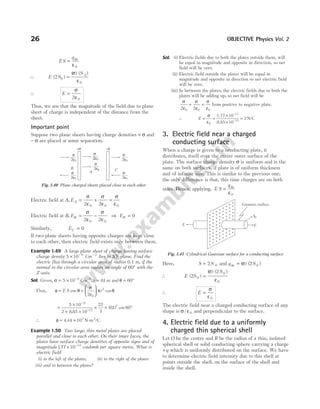
![(A) Taking it together
Assorted questions of the chapter for advanced level practice
1 Figure shows the electric lines of force emerging
from a charged body. If the electric field at A and B
are EA and EB respectively and if the distance
between A and B is r, then
(a) E E
A B
> (b) E E
A B
< (c) E
E
r
A
B
= (d) E
E
r
A
B
= 2
2 The insulation property of air breaks down at
E = ×
3 106
V/m. The maximum charge that can be
given to a sphere of diameter 5 m is approximately
(in coulombs)
(a) 2 10 2
× −
(b) 2 10 3
× −
(c) 2 10 4
× −
(d) 2 10 5
× −
3 The electric field near a conducting surface having a
uniform surface charge density σ is given by
(a)
σ
ε0
and is parallel to the surface
(b)
2
0
σ
ε
and is parallel to the surface
(c)
σ
ε0
and is normal to the surface
(d)
2
0
σ
ε
and is normal to the surface
4 A metallic solid sphere is placed in a uniform
electric field.The lines of force follow the path(s)
shown in figure as
(a) 1 (b) 2
(c) 3 (d) 4
5 Two point charges of 20 µC and 80µC are 10 cm
apart. Where will the electric field strength be zero
on the line joining the charges from 20 µC charge?
(a) 0.1 m (b) 0.04 m
(c) 0.033 m (d) 0.33 m
6 For a dipole q = × −
2 10 6
C and d = 0 01
. m. Calculate
the maximum torque for this dipole, if
E = × −
5 105
NC 1
.
(a)1 10 3 1
× − −
N m
- (b)10 10 3 1
× − −
N m
-
(c)10 10 3
× −
N m
- (d)1 102 2
× N m
-
7 What is the magnitude of a point charge due to
which the electric field 30 cm away has the
magnitude of 2 N/C? [1 4 9 10
0
9 2 2
/ /
πε = × N m C
- ]
(a) 2 10 11
× −
C (b) 3 10 11
× −
C(c) 5 10 11
× −
C (d) 9 10 11
× −
C
8 A charge q is lying at mid-point of the line joining
the two similar charges Q. The system will be in
equilibrium, if the value of q is
(a) Q/2 (b) − Q/2 (c) Q/4 (d) − Q/4
9 Two point charges q and 2q are placed some distance
apart. If the electric field at the location of q be E,
then that at the location of 2q will be
(a) 3E (b) E/2
(c) E (d) None of these
10 The electric field at a distance
3
2
R
from the centre of
a charged conducting spherical shell of radius R is E.
The electric field at a distance
R
2
from the centre of
the sphere is
(a) zero (b) E (c) E/2 (d) E/3
11 Electric field intensity at a point in between two
parallel sheets with like charges of same surface
charge densities ( )
σ is
(a)
σ
ε
2 0
(b)
σ
ε0
(c) zero (d)
2
0
σ
ε
12 Two point charges +2 C and + 6 C repel each other
with a force of 12 N. If a charge of − 4 C is given to
each of these charges, the force now is
(a) 4 N (repulsive) (b) 4 N (attractive)
(c) 12 N (attractive) (d) 8 N (repulsive)
A
r
B
1 1
2 2
3 3
4 4
Exercises
Chapter](https://image.slidesharecdn.com/arihantneetobjectivephysicsvolume2bydcpandey2022edition-230417145135-9bce7664/85/Arihant_NEET_Objective_Physics_Volume_2_By_DC_Pandey_2022_Edition-pdf-42-320.jpg)
![13 Three equal charges are placed on the three corners
of a square. If the force between q1 and q 2 is F12 and
that between q1 and q 3 is F13, then the ratio of
magnitudes ( / )
F F
12 13 is
(a) 1/2 (b) 2 (c) 1 2
/ (d) 2
14 A conductor has been given a charge − × −
3 10 7
C by
transferring electron. Increase in mass (in kg) of the
conductor and the number of electrons added to the
conductor are respectively
(a) 2 10 16
× −
and 2 1031
× (b) 5 10 31
× −
and 5 1019
×
(c) 3 10 19
× −
and 9 1016
× (d) 2 10 18
× −
and 2 10 2
× 1
15 The ratio of electrostatic and gravitational forces
acting between electron and proton separated by a
distance 5 10 11
× −
m, will be (charge on electron
= × −
16 10 19
. C, mass of electron = × −
91 10 31
. kg,
mass of proton = × −
16 10 27
. kg,
G = × −
67 10 11 2 2
. /
N m kg
- )
(a) 2.36 1039
× (b) 2.36 1040
×
(c) 2.34 1041
× (d) 2.34 1042
×
16 Two similar small spheres having +q and −q charge
are kept at a certain distance. F force acts between
the two. If in the middle of two spheres, another
similar small sphere having +q charge is kept, then it
will experience a force in magnitude and direction as
(a) zero, having no direction (b) 8F, towards +q charge
(c) 8F, towards −q charge (d) 4F, towards +q charge
17. Two small conducting spheres of equal radius have
charges +10 µCand −20 µCrespectively and placed at
a distance R from each other. They experience force
F1. If they are brought in contact and separated to the
same distance, they experience force F2. The ratio of
F1 to F2 is
(a) 1 8
: (b) − 8 1
: (c) 1 2
: (d) − 2 1
:
18 A positive point charge is brought near an isolated
conducting sphere as shown in figure. The electric
field is best given by [NCERT Exemplar]
19 The centres of two identical small conducting
spheres are1m apart. They carry charges of opposite
kind and attract each other with a force F. When
they are connected by a conducting thin wire they
repel each other with a force F/3. What is the ratio
of magnitude of charges carried by the spheres
initially?
(a) 1 : 1 (b) 2 : 1
(c) 3 : 1 (d) 4 : 1
20 q, 2q, 3q and 4q charges are placed at the four
corners A, B, C and D of a square. The field at the
centre P of the square has the direction along
(a) AB (b) CB
(c) AC (d) BD
21 A ball with charge − 50e is placed at the centre of a
hollow spherical shell having a charge of − 50e.
What is the charge on the shell’s outer surface?
(a) − 50e (b) Zero
(c) − 100e (d) + 100e
22 Two parallel metal plates having charges + Q and
−Q face each other at a certain distance between
them. If the plate are now dipped in kerosene oil
tank, the electric field between the plates will
(a) became zero (b) increase
(c) decrease (d) remain same
23 A charged block is projected on a rough horizontal
surface with speed v 0 . The value of coefficient of
friction if the kinetic energy of the block remains
constant is
(a)
qE
mg
(b)
qE
m
(c) qE (d) None of these
24 A solid conducting sphere of radius a has a net positive
charge 2Q. A conducting spherical shell of inner radius
b and outer radius c is concentric with the solid sphere
and has a net charge −Q.
32 OBJECTIVE Physics Vol. 2
+q
+q
+q
+q
(a) (b) (c) (d)
q 2q
B
A
D C
4q 3q
P
v0 i
m
q E](https://image.slidesharecdn.com/arihantneetobjectivephysicsvolume2bydcpandey2022edition-230417145135-9bce7664/85/Arihant_NEET_Objective_Physics_Volume_2_By_DC_Pandey_2022_Edition-pdf-43-320.jpg)
![The surface charge density on the inner and outer
surfaces of the spherical shell will be
(a) −
2
4 4
2 2
Q
b
Q
c
π π
, (b) −
Q
b
Q
c
4 4
2 2
π π
,
(c) 0
4 2
,
Q
c
π
(d) None of these
25 The electric flux through the surface
(a) in Fig. (iv) is the largest
(b) in Fig. (iii) is the least
(c) in Fig. (ii) is same as Fig. (iii) but is smaller than Fig. (iv)
(d) is the same for all the figures
26 A mass m = 20 g has a charge q = 3 0
. mC. It moves
with a velocity of 20 ms−1
and enters a region of
electric field of 80 NC−1
in the same direction as the
velocity of the mass. The velocity of the mass after
3s in this region is
(a) 80 ms−1
(b) 56 ms−1
(c) 44 ms−1
(d) 40 ms−1
27 Three concentric metallic spherical shells of radii
R R R
, ,
2 3 are given charges Q Q Q
1 2 3, respectively. It
is found that the surface charge densities on the
outer surfaces of the shells are equal. Then, the ratio
of the charges given to the shells Q Q Q
1 2 3
: : is
(a) 1 : 2 : 3 (b) 1 : 3 : 5
(c) 1 : 4 : 9 (d) 1 : 8 : 18
28 Electric charges q q q
, , − 2 are placed at the corners
of an equilateral triangle ABC of side l. The
magnitude of electric dipole moment of the system is
(a) ql (b) 2ql
(c) 3ql (d) 4ql
29 A point charge +q is placed at a distance d from an
isolated conducting plane. The field at a point P on
the other side of the plane is [NCERT Exemplar]
(a) directed perpendicular to the plane and away from the
plane
(b) directed perpendicular to the plane but towards the
plane
(c) directed radially away from the point charge
(d) directed radially towards the point charge
30 If linear charge density of a wire as shown in the
figure is λ, then
(a) electric field at the centre is
λ
ε
2 0
(b) electric field at the centre of the loop is
λ
πε
2 0R
(c) electric field at the centre of the loop is
λ
πε
λ
ε
2 2
0 0
R R
+
(d) None of the above
31 Figure shown below is a distribution of charges. The
flux of electric field due to these charges through the
surface S is
(a) 3 0
q/ε (b) 2 0
q/ε
(c) q/ε0 (d) zero
32 A cylinder of radius R and length L is placed in a
uniform electric field E parallel to the cylinder axis.
The total flux for the surface of the cylinder is given
by
(a) 2 2
πR E (b) πR E
2
/ (c) ( / )/
π π
R R E
2
(d) zero
33 A square surface of side L metres is in the plane of
the paper. A uniform electric field E (volt/m), also in
the plane of the paper, is limited only to the lower
half of the square surface, (see figure). The electric
flux in SI units associated with the surface is
(a) zero (b) EL2
(c) EL2
0
2
/( )
ε (d) EL2
2
/
34 Two identical conducting spheres carrying different
charges attract each other with a force F when
placed in air medium at a distance d apart. The
spheres are brought into contact and then taken to
their original positions. Now, the two spheres repel
each other with a force whose magnitude is equal to
that of the initial attractive force.
Electric Charges and Fields 33
R
(i) (ii) (iii) (iv)
+q
+q
+q
+q
S
S
S
S
+q
S
+q
+q
a
c
b
E](https://image.slidesharecdn.com/arihantneetobjectivephysicsvolume2bydcpandey2022edition-230417145135-9bce7664/85/Arihant_NEET_Objective_Physics_Volume_2_By_DC_Pandey_2022_Edition-pdf-44-320.jpg)
![47 Among two discs A and B, first has radius 10 cm and
charge10 6
−
C and second has radius 30 cm and
charge10 5
−
C. When they are touched, charges on
both are, q A and qB respectively, will be
(a) q q .
A B
= =
2.75µ µ
C C
, 315
(b) q q
A B
= =
1.09 1.53
µ µ
C C
,
(c) q q
A B
= = 5.5µC
(d) None of the above
48 Two point charges −q and +
q
2
are situated at the
origin and at the point ( , , )
a 0 0 respectively. The
point along the X-axis where the electric field
vanishes is
(a) x
a
=
2
(b) x a
= 2 (c) x
a
=
−
2
2 1
(d) x
a
=
+
2
2 1
49 In figure two positive charges q 2 and q 3 fixed along
theY-axis, exert a net electric force in the
+ x-direction on a charge q1 fixed along the X-axis.
If a positive charge Q is added at ( , )
x 0 , then the
force on q1 [NCERT Exemplar]
(a) shall increase along the positive X-axis.
(b) shall decrease along the positive X-axis.
(c) shall point along the negative X-axis.
(d) shall increase but the direction changes because of the
intersection of Q with q2 and q3
50 A hemisphere is uniformly charged positively. The
electric field at a point on a diameter away from the
centre is directed [NCERT Exemplar]
(a) perpendicular to the diameter
(b) parallel to the diameter
(c) at an angle tilted towards the diameter
(d) at an angle tilted away from the diameter
51 A ring of radius R is uniformly charged. Linear
charge density is λ. An imaginary sphere of radius R
is drawn with its centre on circumference of ring.
Total electric flux passing through the sphere would
be
(a)
2
0
π λ
ε
R
(b)
π λ
ε
R
0
(c) zero (d) None of these
52 Three point charges as shown are placed at the
vertices of an isosceles right angled triangle. Which
of the numbered vectors coincides in direction with
the electric field at the mid-point M of the
hypotenuse?
(a) 1 (b) 2 (c) 3 (d) 4
53 ABC is an equilateral triangle. Charges +q are placed
at each corner. The electric intensity at O (say the
centroid of the triangle) will be
(a)
1
4 0
2
πε
⋅
q
r
(b)
3
4 0
πε
⋅
q
r
(c) zero (d)
1
4
3
0
2
πε
⋅
q
r
54 Equal charges q are placed at the four corners A B C
, ,
and D of a square of length a. The magnitude of the
force on the charge at B will be
(a)
3
4
2
0
2
q
a
πε
(b)
q
a
2
0
2
4πε
(c)
1 2 2
2 4
2
0
2
+
q
a
πε
(d) 2
1
2 4
2
0
2
+
q
a
πε
55 A small element l is cut from a circular ring of radius
a and charge per unit length λ. The net electric field
at the centre of ring is
(a) zero (b)
−λ
πε
l
a
4 0
2
(c) infinity (d)
λ
πε
4 0l
56 Two point charges q1 2
= µC and q 2 1
= µC are placed
at distances b = 1cm and a = 2 cm from the origin of
theY and X-axis as shown in figure. The electric
field vector at point P a b
( , ) will subtend an angle θ
with the X-axis given by
(a) tan θ = 1 (b) tan θ = 2
(c) tan θ = 3 (d) tan θ = 4
Electric Charges and Fields 35
(i) (ii)
Y
q2
q1
q3
Y
q2
q1
q3
Q
x
( , 0)
O
X X
Q q
2 = +
Q q
1 = + Q q
3 = +
M
4
2
3
1
O
r r
+q +q
C
B
A
+q
r
Y
X
q1
q2
O
P a,b
( )
a
b](https://image.slidesharecdn.com/arihantneetobjectivephysicsvolume2bydcpandey2022edition-230417145135-9bce7664/85/Arihant_NEET_Objective_Physics_Volume_2_By_DC_Pandey_2022_Edition-pdf-46-320.jpg)
![4 Assertion The surface charge densities of two
spherical conductors of different radii are equal.
Then, the electric field intensities near their surface
are also equal.
Reason Surface charge density is equal to charge
per unit area.
5 Assertion If a dipole is enclosed by a surface, then
according to Gauss’s law, electric flux linked with it
will be zero.
Reason The net charge enclosed by the surface is
zero.
Statement based questions
1. Figure shows electric field lines in which an electric
dipole p is placed as shown. Which of the following
statements is correct? [NCERT Exemplar]
(a) The dipole will not experience any force
(b) The dipole will experience a force towards right
(c) The dipole will experience a force towards left
(d) The dipole will experience a force upwards
2 Under the influence of the Coulomb field of charge
+Q, a charge −q is moving around it in an elliptical
orbit. Find out the correct statement(s).
(a) The angular momentum of the charge − q is constant
(b) The linear momentum of the charge − q is constant
(c) The angular velocity of the charge − q is constant
(d) The linear speed of the charge − q is constant
3 ‘All charge on a conductor must reside on its outer
surface’. This statement is true
(a) in all cases
(b) for spherical conductors only (Both solid and hollow)
(c) for hollow spherical conductors only
(d) for conductors which do not have any sharp points or
corners
4 Five charges q q q q
1 2 3 4
, , , , and q 5 are fixed at their
positions as shown in figure. S is a Gaussian surface.
The Gauss’s law is given by E dS
q
S
⋅ =
∫ ε0
. Which of
the following statements is correct?
[NCERT Exemplar]
(a) E on the LHS of the above equation will have a
contribution from q q
1 5
, and q q
1 5
, and q3 while q on the
RHS will have a contribution from q2 and q4 only
(b) E on the LHS of the above equation will have a
contribution from all charges while q on the RHS will
have a contribution from q2 and q4 only
(c) E on the LHS of the above equation will have a
contribution from all charges while q on the RHS will
have a contribution from q q
1 3
, and q5 only
(d) Both E on the LHS and q on the RHS will
have contribution from q2 and q4 only
5 Which of the following statement(s) is/are correct?
I. Two identical balls are charged by q. They are
suspended from a common point by two insulating
threads of length l each. In equilibrium, the
maximum angle between the tension in the threads
is 180°. (Ignore gravity).
II. In equilibrium tension in the springs is
T
q q
l
=
⋅
1
4 0
2
πε
(a) Only I (b) Only II
(c) Both I and II (d) None of these
Match the columns
1. Match the following two columns and choose the
option from codes given below.
Column I Column II
A. Electric charge p. [M L T A ]
4
− −
1 3 2
B. Electric field strength q. [MLT A ]
3 1
− −
C. Absolute permittivity r. [MT A ]
3 1
− −
D. Electric dipole s. None
Codes
A B C D
(a) s q p s
(b) s q r p
(c) q p s r
(d) q q p s
2. Match the field lines given in Column I with the
charge configuration due to which field lines exist in
Column II.
Column I Column II
A. p. A pair of equal and
opposite charges
40 OBJECTIVE Physics Vol. 2
–q +q
p
q1
q5
q4
q3
q2
S
O](https://image.slidesharecdn.com/arihantneetobjectivephysicsvolume2bydcpandey2022edition-230417145135-9bce7664/85/Arihant_NEET_Objective_Physics_Volume_2_By_DC_Pandey_2022_Edition-pdf-51-320.jpg)
![Column I Column II
B. q. A pair of positive
charges
C. r. A single positive charge
D. s. A single negative
charge
Codes
A B C D A B C D
(a) s q r q (b) p q r s
(c) s r q p (d) p s r q
3. Four metallic plates are charged as shown in figure.
Now, match the following two columns. Then,
choose the option from codes given below.
Column I Column II
A. Electric field in region-I p. σ
ε0
B. Electric field in region-II q. − σ
ε0
C. Electric field in region-III r. σ
ε
2 0
D. Electric field in region-IV s. zero
Codes
A B C D A B C D
(a) p s q r (b) s p q s
(c) r q q p (d) s s p q
Electric Charges and Fields 41
O
O
O O
I II III IV
σ σ
–2σ
(C) Medical entrances’ gallery
Collection of questions asked in NEET & various medical entrance exams
1 A spherical conductor of radius 10 cm has a charge
of 3.2 10 7
× −
C distributed uniformly. What is the
magnitude of electric field at a point 15 cm from the
centre of the sphere?
1
4 0
πε
= ×
9 10 N-m /C
9 2 2
[NEET 2020]
(a)1.28 105
× N/C (b)1.28 106
× N/C
(c)1.28 107
× N/C (d)1.28 104
× N/C
2 The electric field at a point on the equatorial plane
at a distance r from the centre of a dipole having
dipole moment p is given by (r >> separation of two
charges forming the dipole, ε0 = permittivity of free
space) [NEET 2020]
(a) E
p
=
4 0
3
π ε r
(b) E
p
=
2
4 0
3
π ε r
(c) E
p
= −
4 0
2
π ε r
(d) E
p
= −
4 0
3
π ε r
3 The acceleration of an electron due to the mutual
attraction between the electron and a proton when
they are 1.6 Å apart is,
take, 9 10 Nm C
1.6 10
9 2 2
1
1
4
9 10
0
31
πε
= × − ×
= ×
− −
−
, ~ ,
m
e
e kg
9
[NEET 2020]
(a)1024
m/s2
(b)1023
m/s2
(c)1022
m/s2
(d)1025
m/s2
4 Two point charges A and B, having charges +Q and
−Q respectively, are placed at certain distance apart
and force acting between them is F. If 25% charge of
A is transferred to B, then force between the charges
becomes [NEET 2019]
(a)
9
16
F
(b)
16
9
F
(c)
4
3
F
(d) F
5 Two parallel infinite line charges with linear charge
densities +λ C/m and −λ C/m are placed at a
distance of 2R in free space. What is the electric
field mid-way between the two line charges?
[NEET 2019]
(a)
2
0
λ
πε R
N/C (b)
λ
πε0R
N/C
(c)
λ
πε
2 0R
N/C (d) Zero
O](https://image.slidesharecdn.com/arihantneetobjectivephysicsvolume2bydcpandey2022edition-230417145135-9bce7664/85/Arihant_NEET_Objective_Physics_Volume_2_By_DC_Pandey_2022_Edition-pdf-52-320.jpg)
![6 A hollow metal sphere of radius R is uniformly
charged.
The electric field due to the sphere at a distance r
from the centre [NEET 2019]
(a) zero as r increases for r R
< , decreases as r increases for
r R
>
(b) zero as r increases for r R
< , increases as r increases for
r R
>
(c) decreases as r increases for r R
< and for r R
>
(d) increases as r increases for r R
< and for r R
>
7 Two metal spheres, one of radius R and the other of
radius 2R respectively have the same surface charge
density σ. They are brought in contact and
separated. What will be the new surface charge
densities on them? [NEET Odisha 2019]
(a) σ σ σ σ
P Q
= =
5
6
5
2
, (b) σ σ σ σ
P Q
= =
5
2
5
6
,
(c) σ σ σ σ
P Q
= =
5
2
5
3
, (d) σ σ σ σ
P Q
= =
5
3
5
6
,
8 A sphere encloses an electric dipole with charge
± × −
3 10 6
C. What is the total electric flux across
the sphere? [NEET Odisha 2019]
(a) − × −
3 10 6
N-m2
/C (b) Zero
(c) 3 106
× N-m2
/C (d) 6 10 6
× −
N-m2
/C
9 An electron falls from rest through a vertical distance
h in a uniform and vertically upward directed electric
field E. The direction of electric field is now reversed,
keeping its magnitude the same. A proton is allowed
to fall from rest in it through the same vertical
distance h. The time of fall of the electron, in
comparison to the time of fall of the proton is
[NEET 2018]
(a) 10 times greater (b) 5 times greater
(c) smaller (d) equal
10 Positive charge Q is distributed uniformly over a
circular ring of radius R. A point particle having a
mass ( )
m and a negative charge −q is placed on its
axis at a distance x from the centre. Assuming x R
< ,
find the time period of oscillation of the particle, if it
is released from there [neglect gravity]. [AIIMS 2018]
(a)
16 3
0
3
1 2
π ε
R m
Qq
/
(b)
8 2
0
3
1 2
π ε
R
q
/
(c)
2
3
3
0
3
1 2
π ε
R
q
/
(d) None of these
11 An electric dipole consists of two opposite charges
each 0.05 C
µ separated by 30 mm. The dipole is
placed in an uniform external electric field of
10 NC
6 1
−
. The maximum torque exerted by the field
on the dipole is [AIIMS 2018]
(a) 6 10 3
× −
Nm (b) 3 10 3
× −
Nm
(c) 15 10 3
× −
Nm (d) 1.5 10 3
× −
Nm
12 If point charges Q1
7
2 10
= × −
C and Q2
7
3 10
= × −
C
are at 30 cm separation, then find electrostatic force
between them. [JIPMER 2018]
(a) 2 10 3
× −
N (b) 6 10 3
× −
N (c) 5 10 3
× −
N (d)1 10 3
× −
N
13 Suppose the charge of a proton and an electron differ
slightly. One of them is −e and the other is ( )
e e
+ ∆ .
If the net of electrostatic force and gravitational
force between two hydrogen atoms placed at a
distance d (much greater than atomic size) apart is
zero, then ∆e is of the order (Take, mass of
hydrogen, mh = × −
1.67 10 kg)
27
[NEET 2017]
(a)10 20
−
C (b)10 23
−
C
(c)10 37
−
C (d)10 47
−
C
14 A certain charge Q is divided into two parts q and
Q q
− . How the charge Q and q must be related, so
that when q and ( )
Q q
− is placed at a certain
distance apart experience maximum electrostatic
repulsion? [JIPMER 2017]
(a) Q q
= 2 (b) Q q
= 3 (c) Q q
= 4 (d) Q q c
= +
4
15 Two identical conducting balls A and B have
positive charges q1 and q 2 respectively but q q
1 2
≠ .
The balls are brought together so that they touch
each other and then kept in their original positions.
The force between them is [JIPMER 2017]
(a) less than that before the balls touched
(b) greater than that before the balls touched
(c) same as that before the balls touched
(d) zero
16 A positively charged ball hangs from a silk thread.
We put a positive test charge q 0 at a point and
measure F q
/ 0 , then it can be predicted that the
electric field strength E [JIPMER 2017]
(a) > F q
/ 0 (b) =
F
q
(c) < F q
/ 0 (d) Cannot be estimated
17 An electric dipole is placed at an angle of 30° with
an electric field intensity 2 105
× N/C. It experiences
a torque equal to 4 N-m. The charge on the dipole, if
the dipole length is 2 cm is [NEET 2016]
(a) 8 mC (b) 2 mC
(c) 5 mC (d) 7 µC
18 The electric field in a certain region is acting
radially outward and is given by E Ar
= . A charge
contained in a sphere of radius a centred at the
origin of the field will be given by [CBSE AIPMT 2015]
(a) 4 0
2
πε Aa (b) A a
ε0
2
(c) 4 0
3
πε Aa (d) ε0
3
Aa
42 OBJECTIVE Physics Vol. 2](https://image.slidesharecdn.com/arihantneetobjectivephysicsvolume2bydcpandey2022edition-230417145135-9bce7664/85/Arihant_NEET_Objective_Physics_Volume_2_By_DC_Pandey_2022_Edition-pdf-53-320.jpg)
![19 An electron of mass Me , initially at rest, moves
through a certain distance in a uniform electric field
in time t1 . A proton of mass Mp also initially at rest,
takes time t2 to move through an equal distance in
this uniform electric field. Neglecting the effect of
gravity, the ratio t t
2 1
/ is nearly equal to [AIIMS 2015]
(a) 1 (b)
M
M
p
e
(c)
M
M
e
p
(d)1836
20 A total charge of 5 µC is distributed uniformly on the
surface of the thin walled hemispherical cup. If the
electric field strength at the centre of the
hemisphere is 9 108 1
× −
NC , then the radius of the
cup is
Take, N-m C
2
1
4
9 10
0
9 2
πε
= ×
−
[EAMCET 2015]
(a) 5 mm (b) 10 mm (c) 5 cm (d) 10 cm
21 Two small spherical shells A and B are given positive
charges of 9 C and 4 C respectively and placed such
that their centres are separated by 10 m. If P is a
point in between them, where the electric field
intensity is zero, then the distance of the point P
from the centre of A is [Kerala CEE 2015]
(a) 5 m (b) 6 m (c) 7 m (d) 8 m
(e) 4 m
22 A point charge q is situated at a distance r on axis
from one end of a thin conducting rod of length L
having a charge Q [uniformly distributed along its
length]. The magnitude of electric force between the
two is [Guj. CET 2015]
(a)
kQq
r2
(b)
2kQ
r r L
( )
+
(c)
kQq
r r L
( )
−
(d)
kQq
r r L
( )
+
23 When1019
electrons are removed from a neutral
metal plate through some process, then the charge on
it becomes [Guj. CET 2015]
(a) + 1.6 C (b) − 1.6 C (c)10 C
19
(d)10 C
19
−
24 A charge Q is uniformly distributed over a large
plastic plate. The electric field at point P close to
centre of plate is 10 Vm−1
. If the plastic plate is
replaced by copper plate of the same geometrical
dimension and carrying the same charge Q, then the
electric field at that point will be [CG PMT 2015]
(a) zero (b) 5 Vm−1
(c) 10 Vm−1
(d) 20 Vm−1
25 A uniform electric field is created between two
parallel charged plates as shown below. An electron
enters the field symmetrically between the plates
with a speed of v 0 . The length of each plate is l.
Find the angle of deviation of path of the electron as
it comes out of the field. [CG PMT 2015]
(a) θ = −
tan 1
0
2
El
mv
(b) θ =
−
tan 1
0
2
eEl
mv
(c) θ =
−
tan 1
0
eEl
mv
(d) θ =
−
tan 1
0
2
eE
mv
26 The line AA′ is on charged infinite
conducting plane which is perpendicular
to the plane of the paper. The plane has a
surface density of charge σ and B is ball
of mass m with a like charge of
magnitude q. B is connected by string
from a point on the line AA′. The tangent of angle
( )
θ formed between the line AA′ and the string is
[WB JEE 2015]
(a)
q
mg
σ
ε
2 0
(b)
q
mg
σ
πε0
4
(c)
q
mg
σ
πε
2 0
(d)
q
mg
σ
ε0
27 The angle between the dipole moment and electric
field at any point on the equatorial plane is
[KCET 2015]
(a) 180° (b) 0° (c) 45° (d) 90°
28 Pick out the statement which is incorrect? [KCET 2015]
(a) A negative test charge experiences a force opposite to
the direction of the field.
(b) The tangent drawn to a line of force represents the
direction of electric field.
(c) Field lines never intersect.
(d) The electric field lines form closed loop.
29 A Gaussian surface in the cylinder of cross-section
πa2
and length L is immersed in a uniform electric
field E with the cylinder axis parallel to the field.
The flux φ of the electric field through the closed
surface is [EAMCET 2015]
(a) 2 2
πa E (b) πa L
2
E (c) πa L
2
2
( )
+ E (d) zero
30 Two charges of 10 µC and −10 µC are placed at
points A and B separated by a distance of 10 cm.
Find the electric field at a point P on the
perpendicular bisector of AB at a distance of 12 cm
from its middle point. [UK PMT 2015]
(a)16.4 106
× NC−1
(b) 28.4 106
× NC−1
(c) 8. 2 106
× NC−1
(d) 4.1 106
× NC−1
Electric Charges and Fields 43
+ + + + + + + +
– – – – – – – – – –
l
E
θ
θ
A
B
A′
P
12 cm
–10 C
µ
10 cm
10 C
µ
A B](https://image.slidesharecdn.com/arihantneetobjectivephysicsvolume2bydcpandey2022edition-230417145135-9bce7664/85/Arihant_NEET_Objective_Physics_Volume_2_By_DC_Pandey_2022_Edition-pdf-54-320.jpg)
![31 If the electric field lines is flowing along axis of a
cylinder, then the flux of this field through the
cylindrical surface with the axis parallel to the field
is [where, r = radius of cylinder] [UP CPMT 2015]
(a)
σ
π ε
2 0
r
(b)
σ
ε0
(c) zero (d)
σ
ε
2 0
32 An inclined plane of length 5.60 m making an angle
of 45° with the horizontal is placed in a uniform
electric field E = −
100Vm 1
. A particle of mass 1 kg
and charge10 2
−
C is allowed to slide down from rest
position from maximum height of slope. If the
coefficient of friction is 0.1, then the time taken by
the particle to reach the bottom is [Guj. CET 2015]
(a) 1 s (b) 1.41 s
(c) 2 s (d) None of these
33 Two charged spheres separated at a distance d exert
a force F on each other. If they are immersed in a
liquid of dielectric constant K = 2, then the force (if
all conditions are same) is [UK PMT 2014]
(a) F / 2 (b) F
(c) 2F (d) 4F
34 If a charge on the body is 1 nC, then how many
electrons are present on the body? [KCET 2014]
(a)1.6 1019
× (b) 6.25 109
×
(c) 6.25 1027
× (d) 6.25 1028
×
35 Electric field at a point of distance r from a
uniformly charged wire of infinite length having
linear charge density λ is directly proportional to
[Kerala CEE 2014]
(a) r−1
(b) r
(c) r2
(d) r−2
36 Two equal and opposite charges of masses m1 and m2
are accelerated in a uniform electric field through
the same distance. What is the ratio of their
accelerations, if their ratio of masses is
m
m
1
2
= 0.5?
[KCET 2014]
(a)
a
a
1
2
= 0.5 (b)
a
a
1
2
1
=
(c)
a
a
1
2
2
= (d)
a
a
1
2
3
=
37 An electric dipole of dipole moment p is placed in a
uniform external electric field E. Then, the
[Kerala CEE 2014]
(a) torque experienced by the dipole is E p
×
(b) torque is zero, if p is perpendicular to E
(c) torque is maximum, if p is perpendicular to E
(d) potential energy is maximum, if p is parallel to E
(e) potential energy is maximum, if p is perpendicular to E
38 An electric dipole placed in a non-uniform electric
field experiences [UK PMT 2014]
(a) Both a torque and a net force
(b) Only a force but no torque
(c) Only a torque but no net force
(d) No torque and no net force
39 What is the nature of Gaussian surface involved in
Gauss’s law of electrostatics? [KCET 2014]
(a) Scalar (b) Electrical
(c) Magnetic (d) Vector
40 Two pith balls carrying equal charges are suspended
from a common point by strings of equal length, the
equilibrium separation between them is r. Now, the
strings are rigidly clamped at half the height. The
equilibrium separation between the balls now
becomes [NEET 2013]
(a)
1
2
2
(b)
r
2
3
(c)
2
3
r
(d)
2
3
r
41 An electric charge does not have which of the
following properties? [J&K CET 2013]
(a) Total charge conservation
(b) Quantisation of charge
(c) Two types of charge
(d) Circular line of force
42 The force of repulsion between two electrons at a
certain distance is F. The force between two protons
separated by the same distance is ( )
m m
p e
= 1836
[Kerala CET 2013]
(a) 2F (b) F (c) 1836F (d)
F
1836
43 Equal charge q each are placed at the vertices A and
B of an equilateral triangle ABC of side a. The
magnitude of electric intensity at the point C is
[UP CPMT 2012]
(a)
q
a
4πε0
2
(b)
2
4
q
a
πε0
2
(c)
3
4
q
a
πε0
2
(d)
2
4
q
a
πε0
2
44 If two charges + 4e and +e are at a distance x apart,
then at what distance charge q must be placed from
+e, so that it is in equilibrium? [BCECE (Mains) 2012]
(a)
x
2
(b)
x
3
(c)
x
6
(d)
2
3
x
44 OBJECTIVE Physics Vol. 2
r
y
r´
y/2](https://image.slidesharecdn.com/arihantneetobjectivephysicsvolume2bydcpandey2022edition-230417145135-9bce7664/85/Arihant_NEET_Objective_Physics_Volume_2_By_DC_Pandey_2022_Edition-pdf-55-320.jpg)
![45 If a mass of 20 g having charge 3.0 mC moving with
velocity 20 ms−1
enters a region of electric field of
80 NC−1
in the same direction as the velocity of
mass, then the velocity of mass after 3 s in the
region will be [BCECE 2012]
(a) 40 ms−1
(b) 44 ms−1
(c) 56 ms−1
(d) 80 ms−1
46 The given figure shows a spherical Gaussian surface
and a charge distribution. When calculating the flux
of electric field through the Gaussian surface, then
the electric field will be due to [AMU 2012]
(a) + q3 alone (b) + q1 and + q3
(c) + +
q q
1 3
, and − q2 (d) + q1 and − q2
47 If the electric field is given by ( $ $ $ )
5 4 9
i j k
+ + , then
the electric flux through a surface of area 20 unit
lying in the yz- plane will be [AFMC 2012]
(a) 100 unit (b) 80 unit
(c) 180 unit (d) 20 unit
48 A charge Q is enclosed by a Gaussian spherical
surface of radius R. If the radius is doubled, then the
outward electric flux will [CBSE AIPMT 2011]
(a) be reduced to half (b) remain the same
(c) be doubled (d) increase four times
49 A square surface of side L metre in the plane of the
paper is placed in a uniform electric field E
(volt/metre) acting along the same plane at an angle
θ with the horizontal side of the square as shown in
figure. The electric flux linked to the surface in unit
of N C
m 2 1
−
is [CBSE AIPMT 2011]
(a) EL2
(b) EL2
cosθ
(c) EL2
sinθ (d) zero
50 The electric field at a point due to an electric
dipole, on an axis inclined at an angle θ( )
< °
90 to
the dipole axis, is perpendicular to the dipole axis,
if the angle θ is [KCET 2011]
(a) tan ( )
−1
2 (b) tan ( / )
−1
1 2
(c) tan ( )
−1
2 (d) tan ( / )
−1
1 2
51 A soap bubble is given negative charge, then its
radius will be [DCE 2011]
(a) increase (b) decrease
(c) remain changed (d) fluctuate
52 An electric dipole is placed in an uniform electric
field with the dipole axis making an angle θ with the
direction of the electric field. The orientation of the
dipole for stable equilibrium is [J&K CET 2011]
(a) π/6 (b) π/3
(c) 0 (d) π/2
53 There exists an electric field of 1 N/C along
y-direction. The flux passing through the square of
1 m placed in xy-plane inside the electric field is
[J&K CET 2011]
(a) 1.0 Nm C
2 1
−
(b) 10.0 Nm C
2 1
−
(c) 2.0 Nm C
2 1
−
(d) zero
54 The total electric flux emanating from a closed surface
enclosing an α-particle is (e = electronic charge)
[Kerala CEE 2011]
(a) 2 0
e/ε (b) e/ε0
(c) eε0 (d) ε0 4
e/
(e) 4 0
e/ε
Electric Charges and Fields 45
E
θ
L
L
+ q3
– q2
+ q1](https://image.slidesharecdn.com/arihantneetobjectivephysicsvolume2bydcpandey2022edition-230417145135-9bce7664/85/Arihant_NEET_Objective_Physics_Volume_2_By_DC_Pandey_2022_Edition-pdf-56-320.jpg)
![l CHECK POINT 1.1
1 (d) Negative charge means excess of electron which increases
the mass of sphere B.
2 (a) Charge on the sphere due to removed electrons
q ne
= + = × × −
10 10
14 19
1.6
∴ q = × =
−
1.6 C C
10 16
5
µ
3 (d) A conductor has positive charge. So, there is a deficiency
of electrons.
∴ Number of electrons =
×
×
=
−
−
14.4
1.6
10
10
9
19
19
4 (c) Charge on α-particle, q ne
=
∴ q e
= + = × × −
2 2 10 19
1.6
= × −
3.2 C
10 19
5 (c) As, q ne
= or n
q
e
=
∴Number of extra electrons, n =
×
×
= ×
−
−
80 10
10
5 10
6
19
14
1.6
7 (b) When we rub glass rod with silk, excess electrons are
transferred from glass to silk. So, glass rod becomes positively
charged and silk becomes negatively charged.
9 (a) When positively charged body connected to earth, then
electrons flow from earth to body and body becomes neutral
or uncharged.
l CHECK POINT 1.2
2 (c) Force, F
q
r
= × ⋅
9 109
2
2
⇒ F = × ⋅
×
=
−
9 10
2 10
0 5
9
6 2
2
( )
( . )
0.144 N
3 (b) Force, F
r
1
0
6 6
2
1
4
1 10 5 10
= ⋅
× ×
− −
πε
( )( )
[if distance between them is r]
Also, force, F
r
2
0
6 6
2
1
4
5 10 1 10
= ⋅
× ×
− −
πε
( )( )
∴
F
F
1
2
1
1
=
But direction of F1 and F2 are different.
4 (b) According to Coulomb’s law,
F
r
∝
1
2
⇒
F
F
r
r
1
2
2
1
2
=
∴
5 0 04
0 06
2
2
F
=
.
.
∴ Force between two charges, F2 = 11.25 N
5 (a) F
r
=
+ × − ×
− −
1
4
7 10 5 10
0
6 6
2
πε
( )( )
= −
×
1
4
35 10
0
12
2
πε r
N
F
r r
′ =
+ × − ×
= −
×
− −
1
4
5 10 7 10 1
4
35 10
0
6 6
2
0
12
2
πε πε
( )( )
N
∴ F F
′ =
6 (d) F K
q
r
= ⋅
2
2
If q is halved, r is doubled, then
⇒ F K
q
r
′ =
( / )
( )
2
2
2
2
⇒ F K
q
r
′ =
2
2
16
⇒ F
F
′ =
16
The new force acting on each charge is
F
16
.
7 (d) By using, K
F
F
a
m
=
⇒ K =
×
=
−
−
10
10
4
4
5
2.5
8 (c) We have, F F
= ′ or
QQ
r
QQ
r K
1 2
0
2
1 2
0
2
4 4
πε πε
=
′
⇒ ′ =
r
r
K
9 (d) Gravitational force, F
G m m
r
g
e e
=
( )( )
2
Also, electrostatic force, F
e e
r
e =
1
4 0
2
πε
( )( )
∴
F
F
G m
e
g
e
e
=
( )2
0
2
1
4πε
=
× × ×
× × ×
− −
−
6.67 10 (9.1 10 )
9 10 (1.6 10
11 31 2
9 19 2
)
= × −
2.39 10 43
So, ratio of F F
g e
/ is of order 10 43
−
.
10. (d) They will not experience any force, if | | | |
F F
G e
=
⇒
Gm
r
q
r
2
2
0
2
2
1
4
= ⋅
πε
⇒
q
m
G
2
2 0
4
= πε
⇒ q m G
/ = 4 0
πε
5 × 10⁻⁶
1 × 10⁻⁶
F2 F1
Hints & Explanations](https://image.slidesharecdn.com/arihantneetobjectivephysicsvolume2bydcpandey2022edition-230417145135-9bce7664/85/Arihant_NEET_Objective_Physics_Volume_2_By_DC_Pandey_2022_Edition-pdf-58-320.jpg)
![12. (b) Let FA = Force on charge at C due to charge at A
∴ FA = × ×
× ×
×
=
− −
−
9 10
10 2 10
10 10
9
6 6
2 2
( )
1.8 N
Similarly, FB = Force on charge at point C due to charge at B
= × ×
× ×
×
− −
−
9 109 10 2 10
(10 10 )
6 6
2 2
= 1.8 N
∴ Net force on C,
F F F F F
A B A B
net = + + °
( ) ( ) cos
2 2
2 120
= + + − =
( . ) ( . ) ( . )( . )( / ) .
18 18 218 18 1 2 18
2 2
N
l CHECK POINT 1.3
1. (b) QE mg
= ⇒Q
mg
E
= =
× ×
= ×
−
−
5 10 10
10
5 10
5
7
5
µC
Since, electric field is acting downward, so for balancing
charge must be negative.
2. (b) Electric field, E
Q
r
= × ⋅
9 109
2
= × ×
×
≈ ×
−
9 10
5 10
7 10
9
6
2
4
( )
0.8
N/C
3 (d) Electric field,
E
Q
r
= × ×
9 109
2
⇒ 500 9 10
3
9
2
= × ×
Q
( )
⇒ Q = 0.5µC
4 (a) EA = Electric field at mid-point M due to +5µC charge
= × ×
×
= ×
−
9 10
5 10
45 10
9
6
2
5
(0.1)
N/C
EB = Electric field at M due to +10µC charge
= × ×
× −
9 10
10 10
9
6
2
(0.1)
= ×
90 105
N/C
Net electric field at M B A
= − = ×
| | | |
E E 45 105
N/C
= ×
4.5 106
N/C, in the direction of EB , i.e. towards +5µC
charge.
5 (c) The net field will be zero at a point outside the charges
and near the charge which is smaller in magnitude.
Suppose electric field is zero at P as shown in the figure.
Hence, at P,
k q
L l
k q
l
8 2
2 2
( )
( )
+
=
⋅
⇒l L
=
So, distance of P from origin is, L L L
+ = 2
6 (d) Due to symmetry of charges, electric field intensity is
equal and opposite due to charges. So, they cancel out. Hence,
net electric field due to charge distribution at centre of cube
is zero.
7 (c) At point A and C, electric field lines are dense and equally
spaced, so E E
A C
= .
While at B, they are far apart.
∴ E E E
A C B
= >
8 (c) Electric lines of force never intersect the conductor. They
are perpendicular and slightly curved near the surface of
conductor.
l CHECK POINT 1.4
1. (a) Dipole moment, p q a
= × 2 = × × ×
− −
1.6 4.3
10 10
19 9
= × −
6.8 10 28
C-m
2. (b) On equatorial line electric field is given by
E
p
r
equatorial = ⋅
1
4 0
3
πε
On axial line, E
p
r
axial = ⋅
1
4
2
0
3
πε
∴ E E
axial = 2 equatorial
or E E
a e
= 2
3 (a) Axial electric field, E
kp
r
axis =
2
3
[along P]
Equatorial electric field, E
kp
r
⊥ =
( )
2 3
[opposite to P]
⇒ E
E E
⊥ = =
axis
16 16
0
4 (c) If dipole is rotated through an angle of 90° about its
perpendicular axis, then given point comes on equatorial line.
So, field becomes half of previous value, i.e. E /2.
6 (d) Here, θ1 90
= °
θ2 90 180 270
= ° + ° = °
48 OBJECTIVE Physics Vol. 2
P
l
L
x L
=
x=0
+8q –2q
20 cm
EB EA
+10 C
µ
+5 C
µ M
A B
q
q q
q
q
q
10 cm
FB
+ 1 C
m – 1 C
m
A B
C
+ 2 C
m
FA
120°
60°](https://image.slidesharecdn.com/arihantneetobjectivephysicsvolume2bydcpandey2022edition-230417145135-9bce7664/85/Arihant_NEET_Objective_Physics_Volume_2_By_DC_Pandey_2022_Edition-pdf-59-320.jpg)
![∴ Work done =
= °
= °
∫ pE d
θ
θ
θ θ
1
2
90
270
sin
= − °
°
[ cos ]
pE θ 90
270
= 0
7 (d) Work done in rotating the dipole,
W pE
= −
(cos cos )
θ θ
1 2
= ° − °
pE (cos cos )
0 180
= − − =
pE pE
[ ( )]
1 1 2
8 (d) Maximum torque is given by
τmax = pE [Q sin 90° = 1]
= ×
( )
q a E
2 = × × × × ×
− −
( )
4 10 2 10 4 10
8 4 8
= × −
32 10 4
N-m
If θ =180°, then
work done, W pE
= − °
( cos )
1 180
= − −
pE [ ( )]
1 1
W pE
= 2 = × × −
2 32 10 4
= × −
64 10 4
J
l CHECK POINT 1.5
1 (a) Electric flux through the surface,
φ = ⋅ = + + ⋅ =
E S i j k j
( $ $ $) ( $)
2 4 7 10 40 unit
2 (d) Net electric flux passing from a closed surface in uniform
electric field is always zero.
3 (b) From Gauss’s law,
Net flux =
Total charge enclosed
ε0
= ×
1
0
ε
Q
∴ Q = −
ε φ φ
0 2 1
( )
4 (a) Flux from one face =
1
6
(total flux)
=
1
6 0
q
ε
=
1
3 0
ε
[Qq = 2C]
5 (d) By Gauss’s law, φ
ε
=
1
0
[ ]
Qenclosed
⇒ Qenclosed = = − × + ×
φε ε
0
3 3
0
8 10 4 10
[ ]
= − ×
4 103
0
ε C
8 (d) By using Gauss’s law, E A E E E E A
⋅ = + + + ⋅
∫ ∫
d d
( )
1 2 3 4
= =
+ + +
1
0
1 2 3 4
0
ε ε
[ ]
( )
Q
q q q q
enclosed
9 (a) Electric field, E
r r
=
λ
ε
=
λ
ε
2
2
4
0 0
π π
or λ =
× ε
E r
4
2
0
π
= × ×
×
×
18 10
1
9 10
0 02
2
4
9
.
= × −
2 10 7
C/m
10. (a) Surface charge density, σ =
q
A
=
× −
177 10
200
4
. C/ m2
The electric field outside the sheet is given by
E =
σ
ε
=
×
× × ×
= ×
−
−
2
177 10
2 885 10 200
5 10
0
4
12
5
.
.
N/C
11. (b) Electric field, E = σ ε
/ 0
F Ee
e
= =
σ
ε
=
× ×
×
− −
−
0
(2.0 10 )(1.6 10 )
8.85 10
6 19
12
The work done by the electron against this force in travelling
a distance x metre,W Fx
=
Also, W K
= = = × ×
−
100 10 100
19
eV 1.6 J
∴
( . )( )
.
( )
2 0 10 10
885 10
100 10
6 19
12
19
× ×
×
= × ×
− −
−
−
1.6
1.6
x
x = 0 44
. mm
12. (a) Electric field, E
q
R
=
ε
⋅
1
4 0
2
π
= × ×
× −
( )
.
( . )
9 10
0 2 10
0 25
9
6
2
= ×
2.88 N/C
104
13. (c) We have, E = σ ε
/ 0
⇒ σ = ε = × × −
E 0
12
300 885 10
( . ) = × −
2.6 10 C/m
9 2
(A) Taking it together
1. (a) Electric lines are closer at A. So, the strength of electric
field at A is more than B, i.e. E E
A B
> .
2. (b) Electric field on the surface of a conducting sphere is
E
q
r
= ⋅
1
4 0
2
πε
∴ Charge, q Er
= ⋅
2
0
4πε =
× ×
×
3 10
9 10
6
9
(2.5)2
~
− × −
2 10 3
C
4 (d) Electric line of force are perpendicular to the surface of a
conductor. Inside the sphere, no lines are present.
Hence, option (d) is correct.
5 ( )
c Let neutral point be obtained at a distance x from 20 µC
charge. Hence, at neutral point
1
4
20 10 1
4
80 10
0 10
0
6
2
0
6
2
πε πε
×
=
×
−
− −
x x
( . )
20 80
0
2 2
x x
=
−
( )
0.1
x = + 0 033
. m
Electric Charges and Fields 49
f1 f2
Q
+q
–q
E
90°
E
p
p](https://image.slidesharecdn.com/arihantneetobjectivephysicsvolume2bydcpandey2022edition-230417145135-9bce7664/85/Arihant_NEET_Objective_Physics_Volume_2_By_DC_Pandey_2022_Edition-pdf-60-320.jpg)
![6 (c) Torque, τmax ( ) .
= = = × × × ×
−
pE q d E 2 10 0 01 5 10
6 5
= × −
10 10 3
N-m
7 (a) Electric field due to a point charge, E
q
r
=
4 0
2
πε
∴ q E r
= × = ×
×
×
= × −
4 2
1
9 10
30
100
2 10
0
2
9
2
11
πε C
8 ( )
d For the system to be in equilibrium, net force on charge Q
should be zero. So, Q and q should be unlike in nature.
∴
k Qq
r
kQ Q
r
⋅
+
⋅
=
2 2
2
0
( )
or charge, q
Q
=
−
4
9 (b) As, electric field at q is E, so force on charge q
F qE
= …(i)
Let the electric field at 2q is E′, so force on 2q will be
F qE
′ = ′
2 …(ii)
But, according to Coulomb’s law,
F F
′ = ⇒ 2qE qE
′ = [from Eqs. (i) and (ii)]
⇒ E E
′ = /2
10 (a) Electric field inside shell is zero.
11 ( )
c Situation is shown in the figure
Electric field between two parallel sheets = −
2
2 0
ε
σ σ
( ) = 0
12 ( )
b Force, F k
q q
r
=
1 2
2
⇒ 12
2 6
2
=
×
k
r
…(i)
When a charge of − 4C is given to each of these charges, then
q1 2
= − C , q2 2
= C
and F k
r
′ =
−
( )( )
2 2
2
…(ii)
On dividing Eq. (ii) by Eq. (i), we get
F′
=
−
12
4
12
F′ = − 4 N
Here, negative sign indicates that force is attractive.
13 (b) Force, F
k q
a
12
2
2
=
( )
Force, F
k q
a
13
2
2
2
=
( )
( )
∴ Ratio,
F
F
12
13
2
1
=
14 (d) Here, q = − × −
3 10 7
C
Number of electrons transferred to the conductor is
n
q
e
= =
− ×
− ×
≈ ×
−
−
3 10
10
2 10
7
19
12
C
C
1.6
Mass of one electron, me = × −
91 10 31
. kg
Increase mass of the conductor = ×
m n
e
= × × ×
−
9.1 10 2 10
31 12
= × −
18.2 10 19
kg ≈ × −
2 10 18
kg
15 (a) Gravitational force,
F
Gm m
r
G
e p
= 2
FG =
× × × × ×
×
− − −
−
6.7 10 9.1 10 1.6 10
(5 10
11 31 27
11 2
)
= × −
3.9 10 N
47
Electrostatic force, F
e
r
e =
1
4 0
2
2
πε
Fe =
× × × × ×
×
− −
−
9 10 1.6 10 1.6 10
(5 10 )
9 19 19
11 2
= × −
9.22 10 N
8
So,
F
F
e
G
=
×
×
−
−
9.22 10
3.9 10
8
47
2.36 1039
= ×
16 (c) Situation is shown in figure below
Force between A and C,
F
q
r
= ⋅
1
4 0
2
2
πε
When sphere B is kept at the mid-point of line joining A and
C, then net force on B is
F F F
A C
net = + = ⋅ + ⋅
1
4 2
1
4 2
0
2
2
0
2
2
πε πε
q
r
q
r
( / ) ( / )
= ⋅ ⋅
8
1
4 0
2
2
πε
q
r
= 8F
17 ( )
b We have, q q
q q
1 2
1 2
2
10 20
2
′ ′
= =
+
=
−
= − 5µC
∴
F
F
q q
q q
1
2
1 2
1 2
10 20
5 5
= =
−
− × −
′ ′
( )( )
( ) ( )
= −
8
1
(QF q q
∝ 1 2)
18 (a) When a positive point charge is brought near an isolated
conducting sphere without touching the sphere, then the free
electrons in the sphere are attracted towards the positive
charge making left side negatively charged. This leaves an
excess of positive charge on the rear (right) surface of sphere
as shown below
50 OBJECTIVE Physics Vol. 2
+q +q _q
FA FC
A C
B
r/2 r/2
r
q q
q
a
a
√2a
+
+
+
+
+
+
+
+
+
+
+
+
+
+
E = 0
E ≠ 0 E ≠ 0
σ σ
Attracted negative
charge
+q](https://image.slidesharecdn.com/arihantneetobjectivephysicsvolume2bydcpandey2022edition-230417145135-9bce7664/85/Arihant_NEET_Objective_Physics_Volume_2_By_DC_Pandey_2022_Edition-pdf-61-320.jpg)
![Electric field lines start from positive charge and end at
negative charge (in this case from positive point charge to
negative charge created inside the sphere).
Also, electric field line emerges from a positive charge, in
case of single charge and ends at infinity.
Here, all these conditions are fulfilled in figure (a).
19 (c) From Coulomb’s law,
q q F
1 2 ∝ [Qr = 1m] …(i)
q q q q F
1 2 1 2
2 2 3
– –
∝ …(ii)
Dividing Eq. (i) by Eq (ii), we get
q
q
1
2
3
1
=
20 ( )
b E E
q q
+ 3 is along PA
E E
2 4
q q
+ is along PB
∴ Enet is along CB.
21 (c) Let the induced charge on inner surface and outer surface
is q1 and q2 respectively, then q q e
1 2 50
+ = − .
Here, charge q1 induced due to ball is + 50e.
So, + + = −
50 50
2
e q e
⇒ q e
2 100
= −
22 (c) Electric field in vacuum, E0
0
=
σ
ε
In medium, E
K
2
0
=
σ
ε
If K > 1, then E E
2 0
< .
i.e. if the plates are dipped in kerosene oil tank, the electric
field between the plates will decrease.
23 (a) Force on a charged particle, qE mg
= µ
where, µ is coefficient of friction
∴ µ =
qE
mg
24 (a) Surface charge density ( )
σ =
Charge
Surface area
So, surface charge density on the inner surface
σ
π
inner =
− 2
4 2
Q
b
and surface charge density on the outer surface, σ
π
outer =
Q
c
4 2
25 (d) Gauss’s law of electrostatic states that, the total electric
flux through a closed surface is equal to the charge enclosed
divided by the permittivity, i.e. φ
ε
=
Q
0
. Thus, electric flux
through a surface does not depend on the shape, size or area
of a surface but it depends on the total charge enclosed by the
surface.
So, here in this question, all the figures have same electric
flux as all of them has single positive charge.
26 ( )
b When charged particle enters in a uniform electric field,
then force on charged particle, F qE
=
Also, F ma
=
∴ ma qE
=
or acceleration, a
qE
m
= =
× ×
×
−
−
3 10 80
20 10
3
3
= −
12 ms 2
So, from equations of motion
v u at
= + = + ×
20 12 3 = −
56 ms 1
27 (b) On the outer surfaces of the shell surface charge densities
are equal
Q Q Q
R
Q Q
R
Q
R
3 2 1
2
2 1
2
1
2
4 3 4 2 4
+ +
=
+
=
π π π
( ) ( )
Q Q Q Q Q
3 2 1 2 1
9 4
+ +
=
+
and
Q Q Q
2 1 1
4 1
+
=
⇒ Q Q
2 1
3
=
∴
Q Q Q Q
3 2 1 1
9 1
+ +
= ⇒Q Q
3 1
5
=
Hence, Q Q Q
1 2 3 1 3 5
: : : :
=
28 (c) The situation is shown below.
The direction of dipole moment is shown in figure.
Net electric dipole moment,
p p p pp
net = + + °
2 2
2 60
cos = 3p
= 3 ql [Q p ql
= ]
Electric Charges and Fields 51
–2Q
+2Q
a b
c
– + 2 =
Q Q Q
2R 3R
R
Q1
–Q1
Q Q
1 2
+
Q Q Q
3 2 1
+ +
B C
A
+q
+q – q
2
l l
l
60°
60° 60°
pnet
60°
p
p](https://image.slidesharecdn.com/arihantneetobjectivephysicsvolume2bydcpandey2022edition-230417145135-9bce7664/85/Arihant_NEET_Objective_Physics_Volume_2_By_DC_Pandey_2022_Edition-pdf-62-320.jpg)
![29 (a) When a positive point charge brought near an isolated
conducting plane, then some negative charge developes on
the surface of the plane towards the charge and an equal
positive charge developes on opposite side to the plane. So,
the field at point p on other side in directed perpendicular to
plane and away from it.
30 (d) Electric field at centre due to circular portion is zero
because electric field due to each charged element at centre
will be cancel out by the electric field due the charged
element of its just opposite side.
31 (b) Flux of electric field, φ =
1
ε ε
0
× =
Q q
in
1
2
0
( )
32 (d) Flux through surface A E R
A
, φ π
= × 2
and B,
φ π
B E R
= − × 2
Flux through curved surface C,
φ = ⋅ = ° =
∫ ∫
C d EdS
E S cos 90 0
∴ Total flux through cylinder = + + =
φ φ φ
A B C 0
33 (a) Electric flux, φE d
= ⋅
∫ E S
= ° =
∫ ∫
E dS E dS
cos cos
θ = 90 0
34 (c) F
kQQ
d
1
1 2
2
= and F
k
Q Q
d
2
1 2
2
2
2
=
−
According to question, F F
1 2
=
QQ
Q Q
1 2
1 2
2
4
=
−
( )
⇒ 4 2
1 2 1
2
2
2
1 2
QQ Q Q QQ
= + −
0 6
1
2
2
2
1 2
= + −
Q Q QQ
⇒
Q
Q
1
2
3 8
= ±
35 (c) The acceleration of the electron due to given coulombic
force, F is a
F
m
e
e
= …(i)
where, me is the mass of the electron.
The acceleration of the proton due to same force F is
a
F
m
p
p
= …(ii)
where, mp is the mass of the proton.
On dividing Eq. (ii) by Eq. (i), we get
a
a
m
m
p
e
e
p
=
a
a m
m
p
e e
p
= =
× ×
×
− −
(2.5 10 ms )(9.1 10 kg)
(1.67
22 2 31
10 kg)
27
−
= × ≈ ×
− −
13.6 10 ms 1.5 10 ms
18 2 19 2
36 (a) By using, QE mg
=
⇒ E
mg
Q
= =
×
=
−
−
10 10
10
10
6
6
V m
/ , upward because
charge is positive.
37 ( )
b In Figs. (1), (3) and (4), net electric field is zero because
electric field at a point due to positive charge acts away from
the charge and due to negative charge, it acts towards the
charge. So for Fig. (2),
Here, net electric field in Fig. (2) is
= + + ⋅ °
( ) ( ) ( )( ) cos
2 2 2 2 2 120
2 2
E E E E = 2E
which is not zero.
38 (a) According to Gauss’s law, total flux coming out of a closed
surface enclosing charge q is given by φ =
ε
E S
∫ ⋅ =
d
q
0
.
From this expression, it is clear that total flux linked with a
closed surface only depends on the enclosed charge and
independent of the shape and size of the surface.
φ = ⋅ =
ε
=
∫ E S
d
q
0
20 Vm [given]
This
q
ε0
is constant as long as the enclosed charge is constant.
The flux over a concentric sphere of radius 20 20
cm = V-m.
39 (b) Given, A( , , )
1 0 4 and B( , , )
2 1 5
−
∴ AB i j k
= − + − − + −
[( )$ ( )$ ( ) $]
2 1 1 0 5 4
AB i j k
= − +
[$ $ $]
Torque, τ = ×
p E = ×
qAB E
τ = × − + ×
−
4 10 20
6
($ $ $) $
i j k i
τ = × +
−
8 10 5
($ $
k j)
Magnitude of torque,
τ = × +
−
8 10 1 1
5 2 2
τ = × −
1.13 10 4
N-m
40. (b) Given, E = ×
718 108
. N/C
and r = = × −
2 2 10 2
cm
Electric field is given by
E
r
=
λ
ε
2 0
π
λ = ε
2 0
π rE
λ =
ε
4
2
0
π rE
=
× × ×
× ×
−
2 10 718 10
2 9 10
2 8
9
.
= × −
798 10 4
. C/m
52 OBJECTIVE Physics Vol. 2
E
E
E
E
E
120°
net
C
dS
A B
E](https://image.slidesharecdn.com/arihantneetobjectivephysicsvolume2bydcpandey2022edition-230417145135-9bce7664/85/Arihant_NEET_Objective_Physics_Volume_2_By_DC_Pandey_2022_Edition-pdf-63-320.jpg)
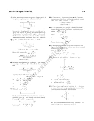
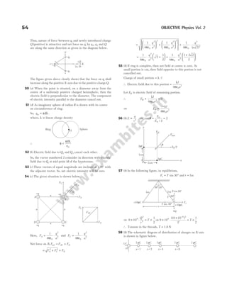
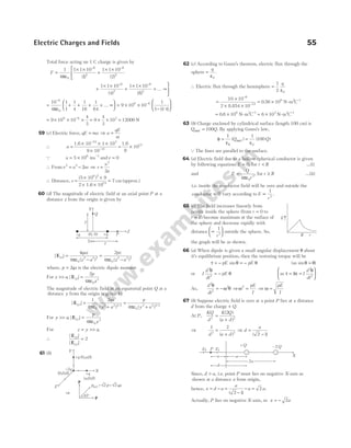
![F
Q Q
r
B = ⋅
1
4
2
2
0
2
πε
( )( / )
( / )
= ⋅ ⋅
2
1
4 0
2
2
πε
Q
r
∴ Net force on C, F F F
B A
net = − = ⋅ =
1
4 0
2
2
πε
Q
r
F
74 (b) The electric field at C due to charge + 107
C at A is
E1
0
7
2
1
4
10
0 2
=
−
πε ( . )
along AC
The electric field at C due to charge − −
10 7
C at B is
E2
0
7
2
1
4
10
0 2
=
−
πε ( . )
along CB
As, | | | |
E E
1 2
=
By symmetry, the vertical components will cancel out and
horizontal components will add.
∴The resultant electric field at C is
E E
= ° = × ×
−
2 60 2
1
4
10
0 2
1
2
1
0
7
2
cos
( . )
πε
=
× ×
= ×
−
9 10 10
0 2
10
9 7
2
4
( . )
/
2.2 N C
75 (c) Number of electrons,
n =
×
× ×
6 10
63.5
10
1
10
23
6
=
×
6 10
63.5
18
As q ne
=
q =
× × × −
6 10 1.6 10
63.5
18 19
or q = × −
1.5 10 C
2
∴ F =
× × × × ×
− −
9 10 1.5 10 1.5 10
10
100
9 2 2
2
= ×
2.0 10 N
8
76 (a) The frequency will be same, f
k
m
=
1
2π
but due to the
constant force i.e. qE, the equilibrium position gets shifted by
qE
k
in forward direction. So, option (a) is correct.
77 (d) Electric field at the centre of charged circular ring is zero.
Hence, electric field at O due to the part ACDB is equal in
magnitude and opposite in direction that due to the part AKB,
i.e. E along OK.
78 (a) On negative charge, the resultant force acts as a restoring
force and proportional to displacement. When it reaches in
the plane xy, then the resultant force is zero and the mass
moves down along Z-axis due to inertia. Thus, oscillation is
set along Z-axis.
79 (a) Total flux, φ φ φ φ
ε
total = + + =
A B C
q
0
Q φ φ
B = and φ φ φ
A C
= = ′ [assumed]
∴ 2
0
′
φ + φ =
ε
q
The flux through the plane surface A, ′ −
φ =
1
2 ε
φ
q
0
80 (a) According to Gauss’s theorem,
E S
∫ ⋅ =
d Q
1
0
ε
enclosed
E x
Q
⋅ =
4 2
0
π
ε
Electric field at the point P, E
Q
x
=
4 0
2
πε
81 (a) Charge density of long wire, λ =
1
3
C-m−1
From Gauss’s theorem, E S
∫ ⋅ =
d
q
ε0
⇒ E dS
q
∫ =
ε0
or E rl
q
2
0
π
ε
=
⇒ E
q
rl
q l
r
= =
2 2
0 0
πε πε
/
⇒
λ
πε
λ
πε
×
×
=
×
2
2 2
2
4
0 0
r r
The magnitude of the electric intensity,
E = × × × ×
× −
9 10
1
3
2
1
18 10
9
2
= × −
0 33 1011 1
. NC
82 (a) Inside the shell A, electric field Ein = 0
Electric Charges and Fields 57
60°
60°
E2
E
E1
C
20 cm
20 cm
A B
+10–7C –10–7C
20 cm
Charge + on
insulating support
Q
S
O x
r
P
r
l
EA
EB
B
rB
x
rA
A
x′
x](https://image.slidesharecdn.com/arihantneetobjectivephysicsvolume2bydcpandey2022edition-230417145135-9bce7664/85/Arihant_NEET_Objective_Physics_Volume_2_By_DC_Pandey_2022_Edition-pdf-68-320.jpg)
![At the surface of shell A,
E
kQ
r
A
A
A
= 2
[a fixed positive value]
Between the shell A and B, at a distance x from the common
centre,
E
k Q
x
A
=
⋅
2
[as x increases, E decreases]
At the surface of shell B,
E
k Q Q
r
B
A B
B
=
−
( )
2
[a fixed negative value because | | | |
Q Q
A B
< ]
Outside the both shell, at a distance x′ from the common
centre,
E
k Q Q
x
A B
out =
−
′
( )
2
[as ′
x increase negative value of Eout
decrease and it becomes zero at x = ∞]
83 (a)QT F
sinθ =
Dividing the two equations, we get
=
ε
q
x
4 0
2
π
and T mg
cos θ =
∴ tanθ
πε
=
1
4 0
2
2
q
x mg
or
x
l
q
x mg
2 4
2
0
2
=
πε
Q tan sin
θ θ
≈ =
x
l
2
or
x
l
q
x
2
2
2
∝ or q x
2 3
∝
⇒ q x
∝
3
2 ⇒
dq
dt
x
dx
dt
∝
3
2
1
2
dq
dt
=
constant
∴ v x
∝
−
1
2 Q v
dx
dt
=
84 (a) From figure, dl R d
= θ,
Charge on dl dq R d
, = λ θ
Electric field at centre due to dl is
dE k
Rd
R
=
λ θ
2
Q λ
π
=
q
R
We need to consider only the component dE cos θ, as the
component dE sinθ will cancel out because of the field at C
due to the symmetrical element dl′.
Total field at centre, | | cos
/
E dE
= ∫
2
0
2
π
θ
= ∫
2
0
2
k
R
d
λ
θ θ
π
cos
/
= =
2
2 2
0
2
k
R
q
R
λ
π ε
85 (b) At a point on the axis of uniformly charged disc at a
distance x from the centre of the disc, the magnitude of the
electric field is,
E
x
x R
= −
+
σ
ε
2
1
0
2 2
At centre, Ec =
σ
ε
2 0
Given that,
E
Ec
=
1
2
Then, 1
1
2
2 2
−
+
=
x
x R
or
x
x R
2 2
1
2
+
=
On squaring both sides, we get
x
x R
2
2 2
4 4
= +
Thus, x
R
2
2
3
= ⇒ x
R
=
3
86 (a) The force acting on the electron = eE.
Acceleration of the electron =
eE
m
+ + + + + + +
Here, s = × −
2 10 2
m, u v
= =
0, ?
∴ v u as
2 2
2
− =
⇒ v
e
m
E
2 2
2 2 10
=
× × −
m
Also,
e
m
= ×
1.76 1011
C/kg
∴ v2
2
= × × × × × −
1.76 10 10 2 10
11 4 2
= ×
704 1013
.
= ×
70 4 1012
.
The velocity of the electron when it reaches plate B,
v ≈ ×
0 85 107
. /
m s
58 OBJECTIVE Physics Vol. 2
q
x
B
Tcosq
F
l
O
l
C
mg mg
Tsinq
x/2
A
T
+
+
+
+
+
+ +
+
+
+
+
dl
dθ
θ
dl
θ
dE
dE cos θ
R
– – – – – –
e E = 10 N/C
4](https://image.slidesharecdn.com/arihantneetobjectivephysicsvolume2bydcpandey2022edition-230417145135-9bce7664/85/Arihant_NEET_Objective_Physics_Volume_2_By_DC_Pandey_2022_Edition-pdf-69-320.jpg)
![87 (a) In equilibrium,
F T
e = sinθ …(i)
and mg T
= cos θ …(ii)
tanθ =
πε
F
mg
q
x mg
e
=
×
2
0
2
4
Also, tan sin
θ θ =
/2
≈
x
L
Hence,
x
L
q
x mg
2 4
2
0
2
=
×
πε
⇒ x
q L
mg
3
2
0
2
4
=
πε
⇒ x
q L
mg
=
2
0
1 3
2πε
88 (b) The three forces acting on each sphere are
(i) tension (ii) weight
(iii) electrostatic force of repulsion
For sphere 1, in equilibrium, from figure,
T M g
1 1 1
cos θ = and T F
1 1 1
sinθ =
∴ tanθ1
1
1
=
F
M g
For sphere 2, in equilibrium, from figure,
T M g
2 2 2
cosθ = and T F
2 2 2
sinθ =
∴ tanθ2
2
2
=
F
M g
Force of repulsion between two charges are same.
∴ F F
1 2
=
Here, θ θ
1 2
= only, if
F
M g
F
M g
1
1
2
2
= ⇒ M M
1 2
=
(B) Medical entrance special format
questions
l Assertion and reason
2. (a) Flux, φ =
net
in
q
ε0
If a closed body is placed in an electric field
(either uniform on non-uniform) total flux linked with it will
be zero,
i.e. φ =
net 0 ⇒ qin = 0
3 (d) If electric lines of force cross each other, then the electric
field at the point of intersection will have two directions
simultaneously which is not possible physically.
4 (b) As σ σ
1 2
= (given)
∴
q
r
q
r
1
1
2
2
2
2
4 4
π π
= , or
q
q
r
r
1
2
1
2
2
2
= [let r1 and r2 be two different radii]
Then, the ratio of electric field intensities near the surface of
spherical conductor,
E
E
q
r
r
q
1
2
1
0 1
2
0 2
2
2
4
4
= ×
πε
πε
= × =
q
q
r
r
1
2
2
2
1
2
1, i.e. E E
1 2
=
5 (a) If a dipole is enclosed by a surface as shown in figure,
then Q Q Q
enclosed = − = 0
∴ φ = 0 (from Gauss’s law)
l Statement based questions
1. (c) The space between the electric field lines is increasing
here from left to right and its characteristics states that,
strength of electric field decreases with increase in the space
between electric field lines. As a result, force on charges also
decreases from left to right.
Thus, the force on charge −q is greater than the force on
charge + q and in turn dipole will experience a force towards
left.
2. (a) Torque about Q of charge −q is zero. So, angular
momentum of the charge −q is constant but distance between
charges is changing. So, force is changing and, hence speed
and velocity are changing.
4 (b) According to Gauss’s law, the term q on the right side of
the equation E S
⋅ =
∫ d
q
S ε0
includes the sum of all charges
enclosed by the surface.
The charges may be located anywhere inside the surface,
if the surface is so chosen that there are some charges inside
and some outside, then the electric field on the left side of
equation is due to all the charges, both inside and outside
of S.
So, E on LHS of the above equation will have a contribution
from all charges while q on the RHS will have a contribution
from q2 and q4 only.
5 (a) In equilibrium, figure can be drawn as
T
q q
l
=
⋅
1
4 2
0
2
πε ( )
Electric Charges and Fields 59
L2
T2 2
sin q
F2
+Q2
M g
2
T2 2
cosq
q2
q1
T2
q2
L1
T1 1
cosq
q1 T1
+Q1
F1
T1 1
sin q
M g
1
M1 M2
–Q +Q
q
q
T sin q
Fe
mg
x
T cos q
T
L L
F F
q q
T
l O
T
l](https://image.slidesharecdn.com/arihantneetobjectivephysicsvolume2bydcpandey2022edition-230417145135-9bce7664/85/Arihant_NEET_Objective_Physics_Volume_2_By_DC_Pandey_2022_Edition-pdf-70-320.jpg)
![60 OBJECTIVE Physics Vol. 2
l Match the columns
1 (a) Electric charge = [AT]
Electric field strength = − −
[ ]
MLT A
3 1
Absolute permittivity = − −
[ ]
M L T A
1 3 4 2
Electric dipole = [ ]
M LTA
0 1 1 1
2 (c) Figures show the field lines around some simple charge
configurations. The field lines of a single positive charge are
radially outward while those of a single negative charge are
radially inward. The field lines around a system of two
positive charges ( , )
q q give a pictorial description of their
mutual repulsion. While that of a pair of equal and opposite
charges shows attraction.
3 (b) E I =
σ + − σ + σ
ε
=
( ) ( )
2
2
0
0
; E II =
σ − − σ + σ
ε
=
σ
ε
( )
2
2 0 0
E III =
σ − σ − σ
ε
= −
σ
ε
( )
2
2 0 0
; E IV =
σ − σ + σ
ε
=
( )
2
2
0
0
(C) Medical entrances’ gallery
1. (a) Given, radius, r = 10 cm = × −
10 10 2
m
Charge, q = × −
3.2 10 7
C
Electric field, E = ?
Electric field at a point (x = 15 cm) from the centre of the
sphere is
E
q
x
=
ε
⋅
1
4 0
2
π
= × ×
×
×
−
−
9 10
32 10
15 10
9
7
2 2
.
( )
= ×
1.28 105
N/C
2 (a) Electric field due to electric dipole on equatorial plane at a
distance r from the centre of dipole is given as
E
p
= ⋅
1
4 3
πε0 r
3 (c) Force due to mutual attraction between the electron and
proton. (when, r = = × −
1.6 1.6
Å 10 10
m) is given as
F
e
r
= × ×
9 109
2
2
= × ×
×
×
−
−
9 109 (1.6 10 )
(1.6 10 )
19 2
10 2
= × −
9 10 N
9
∴Acceleration of electron
=
F
me
=
×
×
−
−
9 10
9 10
9
31
= 1022
m/s2
4 (a) The force between two point charges A and B, having
charges + Q and − Q respectively is given by
F
k Q Q
r
kQ Q
r
kQ
r
A B
= =
−
= −
2 2
2
2
( )
…(i)
where, k = constant =
1
4 0
πε
and r = distance between two charges A and B.
When 25% charge of A is transferred to B, then new amount
of charge on A and B respectively becomes,
Q Q Q
A A
′ = =
75
100
3
4
( )
Q Q Q
B A B
′ = +
25
100
= −
=
−
1
4
3
4
Q Q Q
So, the new force between the two charges now becomes
F
k Q Q
r
k
Q
Q
r
A B
′ =
′ ′
=
−
2 2
3
4
3
4
=
−
=
9
16
9
16
2
2
kQ
r
F [from Eq. (i)]
Thus, the new force between the charges is 9/16 times the
initial force between the charges.
5 (b) Consider two infinite line charges with linear charge
densities + λ C/m and − λ C/m respectively, which are lying
in y-direction as shown in the figure below
Then, the electric field due to line A at the mid-way between
the two line charges, i.e. at R is
| |
EA
R
=
λ
πε
2 0
N/C … (i)
which lies along positive x-axis (outward), i.e. from A to B.
Similarly, the electric field due to line B at the mid-way
between the two line charges, i.e. at R is
| |
EB
R
=
λ
πε
2 0
N/C …(ii)
q >0
(B)
q <0
(A)
(D)
+q –q
+ +
q q
(C)
r
A B
−Q
+Q
–
+
–
+
–
+
–
+
–
+
–
+
–
+
+λ –λ
A B
2R
R
EB
EA](https://image.slidesharecdn.com/arihantneetobjectivephysicsvolume2bydcpandey2022edition-230417145135-9bce7664/85/Arihant_NEET_Objective_Physics_Volume_2_By_DC_Pandey_2022_Edition-pdf-71-320.jpg)
![Due to negative charge on B, EB also lies along positive x-axis
(inward), i.e. from A to B.
So, the resultant electric field at R is given as
| | | | | |
E E E
R A B
= +
Substituting the values from Eqs. (i) and (ii), we get
| |
ER
R R
= +
λ
πε
λ
πε
2 2
0 0
=
λ
πε0R
N/C
which also lies along the positive x-axis, i.e. from A to B.
6 (a) As the hollow sphere is uniformly charged, so the net
charge will appear on the surface of the sphere.
(i) The electric field at a point outside the hollow sphere is
φ
ε
= ⋅ =
∫ E S
d
Q
S
enclosed
0
[from Gauss’ law]
⇒ E r
Q
( )
4 2
0
π
ε
=
⇒ E
Q
r
=
4 0
2
πε
⇒ E
r
∝
1
2
(ii) The electric field at the surface ( )
r R
= ,
E
Q
R
=
4 0
πε
(iii) The electric field inside hollow sphere ( )
r R
< is
E
Q
r
= =
4
0
0
πε
[ ]
QQinside = 0
7 (d) The surface charge density of a closed metal sphere having
charge Q is given by
σ =
Charge
Area
=
Q
A
or Q A
= σ
Thus, the charges on sphere P and Q having same charge
density as shown in the figure below is given by
Q R
P = ×
σ π
4 2
= 4 2
πσR …(i)
and Q R
Q = ×
σ π
4 2 2
( ) = 16 2
πσR …(ii)
When they are brought in contact with each other, the total
charge will be
Q Q Q
t P Q
= +
= +
4 16
2 2
πσ πσ
R R [from Eqs. (i) and (ii)]
= 20 2
πσR …(iii)
When two metallic charged spheres are connected to each
other, then charge is flowing the sphere of higher potential to
the sphere of lower potential till they may attain at common
potential.
Q
R
Q
R
P Q
4 4 2
0 0
π ε π ε
=
⇒
Q
R
Q
R
P Q
=
2
⇒
Q
Q
P
Q
=
1
2
So, the new charges on the sphere P and Q after separation
will be distributed as
⇒ Q Q
P t
′ =
1
3
and Q Q
Q t
′ =
2
3
After separation, the new surface charge densities on P and Q
will be
σP
P
Q
=
′
Area
=
1
3
Qt
Area
=
1
3
20
4
2
2
πσ
π
R
R
=
5
3
σ
and σQ
Q
Q
=
′
Area
=
2
3
Qt
Area
= ×
2
3
20
4 2
2
2
πσ
π
R
R
( )
= × =
2
3
5
4
5
6
σ σ
8 (b) When a sphere encloses a charged dipole,
Here, q = ± × −
3 10 6
C
Thus, according to Gauss’s law, the net electric flux across the
closed surface is equal to the net charge enclosed by it divided
by ε0, i.e.
φ =
ε
E
q in
0
=
+ × − ×
ε
=
− −
3 10 3 10
0
6 6
0
Hence, electric flux across the sphere is zero.
9 (c) Force on a charged particle in the presence of an electric
field is given as
F qE
= …(i)
Electric Charges and Fields 61
dS
E
R
r
O
+
+
+
+
+
+
+
+
+
+ + +
Q
+
+
+
+
σ
R
P
σ
2R
Q
+q –q](https://image.slidesharecdn.com/arihantneetobjectivephysicsvolume2bydcpandey2022edition-230417145135-9bce7664/85/Arihant_NEET_Objective_Physics_Volume_2_By_DC_Pandey_2022_Edition-pdf-72-320.jpg)
![where, q is the charge on the charged particle and E is the
electric field.
From Newton’s second law of motion, force on a particle with
mass m is given as
F ma
= …(ii)
where, a is the acceleration.
From Eqs. (i) and (ii), we get
F ma qE
= =
⇒ a
qE
m
= …(iii)
Now, consider that a particle falls from rest through a vertical
distance h. Therefore, u = 0 and the second equation of motion
becomes
h ut at
= +
1
2
2
or h t at
= × +
0
1
2
2
= ×
1
2
2
qE
m
t [from Eq. (iii)]
⇒ t
hm
qE
2 2
= or t
hm
qE
=
2
Since, the particles given in the question are electron and
proton and the quantity 2h qE
/ (here, q q e
p e
= = ) for both of
them is constant. Thus, we can write
t k m
=
where, k
h
qE
=
2
or t m
∝
As, mass of proton ( )
mp >> mass of electron ( )
me .
Thus, the time of fall of an electrons would be smaller than
the time of fall of a protons.
10 (a) When the negative charge is shifted at a distance x from the
centre of the ring along its axis, then force acting on the point
charge due to the ring is
F qE
= (towards centre)
= ⋅
+
q
kQx
R x
( ) /
2 2 3 2
If R x
>> , then R x R
2 2 2
+ −
~
and F
Qqx
R
=
ε
⋅
1
4 0
3
π
(towards centre)
Since force on charged particle is acting in opposite direction of
electric field, hence acceleration of charged particle towards the
centre of ring is given by
⇒ a
F
m
Qqx
mR
= − = −
ε
⋅
1
4 0
3
π
Since, restoring force F x
E ∝ − , therefore motion of charged
particle will be SHM.
Acceleration on charged particle is also given by
a x
= −ω2
−
ε
= −
1
4 0
3
2
π
ω
Qq x
mR
x
ω
πε
=
Qq
mR
4 0
3
Time period of SHM, T
R m
Qq
= =
ε
2 16 3
0
3 1 2
π
ω
π
/
11 (d) Given, q = 0.05 C
µ = × −
5 10 8
C,
2a = 30 mm= 0.03 m
and E = −
106 1
NC
Torque acting on an electric dipole placed in an uniform
electric field,
τ θ
= pE sin
For maximum torque, θ = °
90
∴ τmax = pE = ×
E q a
( )
2
= × × ×
−
10 5 10 0.03
6 8
= × −
1.5 10 3
N-m
12 (b)Q Electrostatic force, F k
QQ
r
= 1 2
2
= × ×
× × ×
×
− −
−
9 10
2 10 3 10
30 10
9
7 7
2 2
( )
= × −
6 10 3
N
13 (c) Net charge on one H-atom,
q e e e e
= − + + =
∆ ∆
Net electrostatic repulsive force between two H-atoms,
F
kq
d
r =
2
2
=
k e
d
( )
∆ 2
2
Similarly, net gravitational attractive force between two
H-atoms,
F
Gm
d
G
h
=
2
2
It is given that, F F
r G
− = 0
⇒
k e
d
Gm
d
h
( )
∆ 2
2
2
2
0
− =
⇒ ( )
∆e
Gm
k
h
2
2
=
( )
∆e 2
=
× ×
×
− −
(6.67 10 ) (1.67 10 )
9 10
11 27 2
9
⇒ ∆e = × −
1.437 10 C
37
∴Order is ∆e is 10 37
−
C.
14 (a) The electrostatic force of repulsion between the charge q
and ( )
Q q
− at separation r is given by
F
q Q q
r
= ⋅
−
1
4 0
2
πε
( )
= ⋅
−
1
4 0
2
2
πε
qQ q
r
62 OBJECTIVE Physics Vol. 2
−q
x
Q](https://image.slidesharecdn.com/arihantneetobjectivephysicsvolume2bydcpandey2022edition-230417145135-9bce7664/85/Arihant_NEET_Objective_Physics_Volume_2_By_DC_Pandey_2022_Edition-pdf-73-320.jpg)
![22 (d) As a point charge q is situated at a distance r on axis from
one end of a thin conducting rod of length L having charge Q
as shown in figure.
Total charge = Q
Consider an elementary charge dq having length dx at a
distance x from the charge q, then
dq dx
Q
L
dx
= =
ρ
Now, force between dq and q
dF
q dq
x
=
1
4 0
2
π ε
= k
q Q dx
L x2
∴ Total force, F dF
k Q q
L
x dx
r
r L
= =
∫ ∫
−
+
2
= −
+
kQq
L x r
r L
1
=
−
+
−
kQq
L r L r
1 1
=
− − −
+
=
+
kQq
L
r r L
r L r
kQq
r r L
( ) ( )
23 (a) As, 1019
is removed from the neutral metal.
So, loss of charge = × ×
−
1.6 10 10
19 19
= 1.6 C
So, charge on metal = +1.6C
24 (c) Electric field at centre of plastic sheet is the same as at
close to the centre of the copper plate.
25 (b) Initial velocity of the electron along x-direction,
u v
x = 0
As, applied electric field is vertical,
v u v
x x
= = 0
⇒ uy = 0 and v u a t
y y y
= +
or v
eE
m
l
v
y = + ×
0
0
[Ql v t
= 0 ]
or v
eEl
mv
y =
0
We can write, tanθ =
v
v
y
x
⇒ tanθ = × =
eEl
mv v
eEl
mv
0 0 0
2
1
⇒ θ =
−
tan 1
0
2
eEl
mv
26 (a) The diagram is as follows
The electric field due to charged infinite conducting sheet is
E =
σ
ε
2 0
Now, force (electric force) on the charged ball is
F qE
q
= =
σ
ε
2 0
The resultant of electric force and mg balance the tension
produced in the string.
So, tanθ =
F
mg
= =
q
mg
q
mg
σ ε σ
ε
/ 2
2
0
0
27 (a) The angle between the dipole moment and electric field at
any point on the equatorial plane is 180°.
28 (d) Electric field lines does not form closed loop as it
originates from the positive charge and terminate at negative
charge. So, the option (d) is incorrect.
29 (d) Gaussian surface is given below,
Net flux crossing through surface of cylinder is given by
φ = Flux through upper disc + Flux through lower disc
+ Flux through curved surface
= + − +
E a E a
( ) ( )
π π
2 2
0
= −
π π
a E a E
2 2
= 0
30 (d) At equatorial, electric field,
E
ql
r l
=
× ×
+
9 10 2
9
2 2 3 2
( ) /
(Ql = 5 cm)
E =
× × × × × ×
+
− −
9 10 2 5 10 10 10
012 0 05
9 2 6
2 2 3 2
[( . ) ( . ) ] /
Electric field, E ~ .
− ×
41 106
N/C
64 OBJECTIVE Physics Vol. 2
+ + + + + + + +
– – – – – – – – – –
l
E
v0 q
Y
X
q
A
A¢ mg
F =
B q
—
—
s
e
2 0
T
E
E
– +
⊥ bisector
–q +q
P
r L
+
x
r
dx
L
q
L
E
a](https://image.slidesharecdn.com/arihantneetobjectivephysicsvolume2bydcpandey2022edition-230417145135-9bce7664/85/Arihant_NEET_Objective_Physics_Volume_2_By_DC_Pandey_2022_Edition-pdf-75-320.jpg)
![31 (c) Assuming the small area ∆S on the cylindrical surface. The
normal to this area will be perpendicular to the axis of the
cylinder, but the electric field is parallel to axis.
Hence, ∆ ∆
φ θ
= ⋅
E S cos = ⋅
E S
∆ cos
π
2
= 0
32 (b) The figure of the above situation is shown below
The electric field, E = −
100V m 1
For the downward motion of the particle of mass 1kg.
mg qE
sin cos
45 45
°− ° −µ ( )
mg qE
cos sin
45 45
° + ° =ma
⇒1 10
1
2
1
100
100
1
2
1
10
× × − × × −
1 10
1
2
1
100
100
1
2
1
× × + × ×
= ×a
⇒
10
2
1
2
1
10
10
2
1
2
− − +
=a
⇒
10
2
1
2
1
2
1
10 2
− − − =a
⇒ a
.
= =
79
10 2
79
2
⇒ a ≈ −
5.6ms 2
Now, time taken by the particle to cover 56 m distance along
the incline plane is t
s
a
= =
×
2 2 5.6
5.6
= =
2 1.41 s
33 (a) Consider the situation shown in the diagram.
Let charges on sphere A and B are q1 and q2, respectively.
Force between the charges placed in air by Coulomb’s law
(spheres can be assumed as point charges placed at their
centres)
F k
q q
d
AB = 1
1 2
2
…(i)
where, k1
0
1
4
=
πε
When the spheres are immersed in a liquid, force between
the charges is ′ = = ×
F
q q
d
q q
K d
AB
r
1 2
2
1 2
0
2
4 4
1
πε πε
=
×
× = ×
1
4 2 2
0
1 2
2
1 1 2
2
( )
πε
q q
d
k q q
d
…(ii)
where, K is dielectric constant of the liquid = 2
From Eqs. (i) and (ii), we get
F
F
k
k
AB
AB
′
= =
1
1 2
2
/
According to question, F F
AB =
⇒
F
FAB
′
= 2 ⇒ ′ =
F
F
AB
2
34 (b) Given, charge on the body,
q = = × × −
1nC 1 1 10 C
9
(Q 1nC 10 C)
9
= −
Charge on the electron e = × −
1.6 10 19
From the property of quantisation of charge, q ne
=
⇒ Number of charges, n
q
e
= =
×
×
−
−
1 10
1.6 10
9
19
= × ×
−
0.625 10 10
9 19
= ×
6.25 109
35 (a) We know that, electric field at distance r from an
infinitely long linear charge is given by
E
r
=
λ
πε
2 0
⇒ λ πε
= ⋅
2 0 rE or E r
∝ −1
36 (c) We know that, force experienced by charge in electric field
F q E m a
1 1 1 1
= = …(i)
F q E
2 2
= = m a
2 2 …(ii)
As, q q
1 2
= ⇒ F F
1 2
=
From Eqs. (i) and (ii), we get
a
a
F m
F m
1
2
1 1
2 2
=
/
/
=
⋅
⋅
F m
F m
2
1
⇒
a
a
m
m
1
2
2
1
10
5
2
= = = =
1
0.5
Q
m
m
1
2
=
0.5
37 (c) Torque on dipole form, τ θ
= ×
p E sin
So, torque is maximum if p is perpendicular to E.
Potential energy,U p p
= − −
E E
= cosθ
Hence, when θ = °
180 , i.e. p is anti-parallel to E, then
potential energy will be maximum.
38 (a) Consider the diagram, where an electric dipole is placed in
non-uniform electric field.
Electric field at the sight of q is E1
and electric field at the sight of −q is E2
F1 = force on the charge q qE
= 1
F2 = force on the charge − = −
q qE2
Net force on the dipole, F F F q E E
= + = −
1 2 1 2
( )
Q | | | |
E E
1 2
≠ , so, F F
1 2
≠ or | |
F ≠ 0
τ1 = torque on the dipole due to E1 = ×
p E1
[clockwise]
Electric Charges and Fields 65
d
B
A
d
A B
Sphere Sphere
F2
E2
F1
d
q
−q
O
E1
q = 45º
mg sin
q
mg cos q
X-axis
F = friction
m=1kg
q =10 C
-2
m= 0.1
mg
5.6 m
E cos 45º
E sin 45º
E
45º
M
otion
q](https://image.slidesharecdn.com/arihantneetobjectivephysicsvolume2bydcpandey2022edition-230417145135-9bce7664/85/Arihant_NEET_Objective_Physics_Volume_2_By_DC_Pandey_2022_Edition-pdf-76-320.jpg)
![τ2 = torque on the dipole due to E2 = ×
p E1
[clockwise]
where, p q d
= is dipole moment of the dipole,
τ τ τ
net = +
1 2 = × + ×
p E p E
1 2 ≠ 0
Hence, both torque ( )
τnet and force ( )
F act on the dipole.
39 (d) The Gauss’s law of electrostatics gives a relation between
electric flux through any closed hypothetical surface (called a
Gaussian surface) and the charge enclosed by the surface.
So, the nature of Gaussian surface is vector.
40 (b) tanθ =
F
mg
⇒
r
y
kq
r mg
/ 2 2
2
= ⇒ y r
∝ 3
Therefore,
r
r
y
y
′
=
3
2
/
⇒ r r
′ =
1
2
1 3
/
41 (d) Electric lines of force forms open loops while magnetic
lines of force forms closed loops.
42 (b) In same medium, the force between two protons separated
by same distance will F, as it is independent of the masses but
depends on the charge of the particle.
43 (c)
Here, E E
q
a
1 2
0
2
1
4
= = ⋅
πε
⇒ E E E E E
′ = + +
1
2
2
2
1 2
2 cosθ
Given, θ = °
60
E E
′ = 3 1
2
⇒ E
q
a
′ =
3
4 0
2
π ε
44 (b) For equilibrium of q,
| | | |
F F
1 2
=
∴
1
4 0
1
1
2
πε
qq
x
=
1
4 0
2
2
2
πε
qq
x
x
x
q
q
2
1
2
1
=
+
=
+
=
x
e
e
x
4
1
3
45 (c) As the mass is moving in the electric field, then
ma qE
=
⇒ a
qE
m
= =
× ×
×
=
−
−
−
3 10 80
20 10
12
3
3
2
ms
By using, v u at
= +
v = + × = −
20 12 3 56 1
ms
46 (c) The electric field is due to all charges present whether
inside or outside the given surface. So option (c) is correct.
47 (a) Electric flux is equal to the scalar product of an area vector
and electric field E. As the surface is lying in yz-plane,
∴ φ = ⋅ = + +
E A i j k i
d ( $ $ $) ( $)
5 4 9 20 = 100 unit
48 (b) Total flux =
ε
Net enclosed charge
0
Hence, we can say that the electric flux depends only on net
charge enclosed by surface. So, flux will remain the same.
49 (d) Flux of electric field E through any area A is defined as
φ = EA cos θ
The lines are parallel to the surface.
⇒ Angle between E and A = °
90 , hence φ = 0.
50 (c) Here, α θ
+ = °
90
If the net field from the inclined axis makes angle θ, then
⇒ tan tan
α θ
=
1
2
⇒ tan tan
θ α
= 2 = °−
2 90
tan( )
θ
⇒ tan2
2
θ = ⇒ tanθ = 2
⇒ θ = −
tan ( )
1
2
51 (a) If σ is the surface tension and r is the radius of soap
bubble, then pexcess = 4σ /r
When the bubble is charged, p p
r
excess electrostatics
= +
4σ
After electrification, surface tension decreases.
This decrease the pressure and increase the radius p
r
∝
1
.
52 (c) For stable equilibrium, the angle θ should be zero.
53 (d) The flux passing through the square of 1 m placed in
xy-plane inside the electric field is zero because number of
field lines entering are equal to number of field lines (flux)
leaving the surface. So, net flux will be zero.
54 (a) As, we know that, charge on α-particle is double to that on
electron.
Q By Gauss’ theorem, φ
ε
E
q
=
0
⇒ | |
φ
ε ε
E
e e
=
−
=
2 2
0 0
66 OBJECTIVE Physics Vol. 2
F1
F2 q e
2 = +
q e
1 = + 4
x1 x2
x
q
60°
E2
E1
E2
E¢
B
A
−q +q
E
τ θ
= sin
= 0
pE
E
α
α
θ
Dipole
axis](https://image.slidesharecdn.com/arihantneetobjectivephysicsvolume2bydcpandey2022edition-230417145135-9bce7664/85/Arihant_NEET_Objective_Physics_Volume_2_By_DC_Pandey_2022_Edition-pdf-77-320.jpg)
![The electric field around a charge can be described in two ways by an electric
field ( )
E and in the form of electrostatic or electric potential ( )
V .
The electric field ( )
E is a vector quantity and we have already discussed about it
in detail in the previous chapter.
In this chapter, we will study about the electric potential and how these
quantities are interrelated to each other. We will also study about capacitor, i.e. a
device used for storing electric energy.
ELECTRIC POTENTIAL
The electric potential at any point in the region of electric field is defined as the
amount of work done in bringing a unit positive test charge from infinity to that
point along any arbitrary path. It is a scalar quantity and is denoted byV.
Electric potential ( )
( )
V
W
q
=
Work done ( )
Charge 0
According to the nature of charge, electric potential can be positive (due to
positive charge), negative (due to negative charge) or zero.
Unit and dimensional formula of electric potential
Its SI unit is volt ( )
V and 1 volt =
1 joule
1 coulomb
and CGS unit is stat volt (esu), where 1 volt =
1
300
stat volt
Its dimensional formula is [ML T A ].
2 3 1
− −
Example 2.1 How much work will be done in bringing a charge of 400 µC from infinity
to some point P in the region of electric field? Given that the electric potential at point
P is 20V.
Sol. Electric potential at any point can be written as,
Electric potential ( )
)
( )
V
W
q
=
work done
charge
(
0
… (i)
02
Electrostatic Potential
and Capacitance
CHAPTER
Inside
1
2
3
4
Electric potential
Equipotential surfaces
Electric potential energy
Electrostatic potential due
to a point charge
Variation of electric potential
on the axis of a charged ring
Special method to solve
combination of capacitors
Electrostatics of conductors
Electrostatic potential due to a
system of charges
Potential energy of a system
of charges
Dielectrics and polarisation
Combination of capacitors
Energy stored in charged
capacitor
Electric potential due to a
continuous charge distribution
Electric potential due to
electric dipole
Potential due to charged sphere
Motion of charged particle
in electric field
Capacitors and capacitance
Parallel plate capacitor
Common potential
Kirchhoff’s law for capacitor
circuits
van de Graaff generator
5](https://image.slidesharecdn.com/arihantneetobjectivephysicsvolume2bydcpandey2022edition-230417145135-9bce7664/85/Arihant_NEET_Objective_Physics_Volume_2_By_DC_Pandey_2022_Edition-pdf-78-320.jpg)
![Given, VP = 20V and q0
6
400 400 10
= = × −
µC C
On putting the values in Eq. (i), we get
20
400 10 6
=
× −
W
∴ W = × × = ×
− −
20 400 10 8 10
6 3
J
Example 2.2 Find the work done by some external force in
moving a charge q C
= 2 µ from infinity to a point, where
electric potential is 104
V.
Sol. Given, charge, q = 2 µC = × −
2 10 6
C and electric potential,
V = 104
V
Using the relation,W qV
=
We have, W = ×
( ) ( )
–
2 10 10
6 4
= × −
2 10 2
J
Electric potential difference
The electric potential difference between two points A and
B is equal to the work done by the external force in
moving a unit positive charge against the electrostatic
force from point B to A along any path between these two
points.
IfVA andVB be the electric potential at point A and B
respectively, then ∆V V V
A B
= −
or ∆V
W
q
AB
=
The SI unit of potential difference is volt ( )
V .
The dimensional formula for electric potential difference is
given by [ML T A ].
2 3 1
− −
Note Following three formulae are very useful in the problems related
to work done in electric field.
( ) ( )
W q V V
a b a b
− = −
electric force 0
( ) ( ) ( )
W q V V W
a b b a a b
− −
= − = −
external force electric for
0 ce
( )
W q V
a a
∞ − =
external force 0
Here, q Va
0, and Vb are to be substituted with sign.
Example 2.3 The electric potential at point A is 20 V and
at B is − 40 V. Find the work done by an external force
and electrostatic force in moving an electron slowly from
B to A.
Sol. Here, the test charge is an electron, i.e.
q0 – 1.6 10 C
–19
= ×
VA = 20 V
and VB = − 40 V
Work done by external force,
( ) ( )
W q V V
B A A B
− = −
external force 0
= − × − −
−
( 1.6 10 ) [(20) ( 40)]
19
= − × −
9.6 10 J
18
Work done by electric force,
( ) ( )
W W
B A B A
− −
= −
electric force external force
= − − × −
( 9.6 10 J)
18
= × −
9.6 10 J
18
Note Here, we can see that an electron (a negative charge) moves
from B (lower potential) to A (higher potential) and the work
done by electric force is positive. Therefore, we may conclude
that whenever a negative charge moves from a lower potential to
higher potential, work done by the electric force is positive or
when a positive charge moves from lower potential to higher
potential, the work done by the electric force is negative.
Electrostatic potential due
to a point charge
Let P be the point at a distance r from the origin O at
which the electric potential due to point charge + q is
required.
The electric potential at a point P is the amount of work
done in carrying a unit positive charge from ∞ to point P.
Suppose a test charge q 0 is placed at point A at distance x
from O.
The electrostatic force acting on charge q 0 is given by
F
q
x
=
1
4 0
0
2
πε
, along OA …(i)
Small work done in moving the charge through a small
distance dx from A to B is given by
dW d
= ⋅
F x = ° = −
Fdx Fdx
cos180
(Qcos 180 1
° = − )
Total work done in moving a positive test charge q 0 from
∞ to the point P is given by
W Fdx
qq
x
dx
r r
= − = −
∞ ∞
∫ ∫
1
4 0
0
2
πε
= −
∞
−
∫
qq
x dx
r
0
0
2
4πε
= −
−
∞
qq
x
r
0
0
4
1
πε
= −
∞
qq
r
0
0
4
1 1
πε
Q x dx
x
−
∫ = −
2 1
68 OBJECTIVE Physics Vol. 2
A
B
q3
q2
q1
q4
V
V
V
V
V
Fig 2.1 Electric potential between points A and B
∞
E
A
B
P
O
+q
r
dx
x
q0
Fig. 2.2 Electrostatic potential at point due to a point charge](https://image.slidesharecdn.com/arihantneetobjectivephysicsvolume2bydcpandey2022edition-230417145135-9bce7664/85/Arihant_NEET_Objective_Physics_Volume_2_By_DC_Pandey_2022_Edition-pdf-79-320.jpg)
![W
qq
r
= 0
0
4πε
…(iii)
From the definition of electric potential,
∴ V
W
q
q
r
= =
0 0
4πε
...(iv)
A positively charged particle produces a positive electric
potential. A negatively charged particle produces a
negative electric potential.
Here, we assume that electrostatic potential is zero at
infinity. Eq. (iv) shows that at equal distances from a point
charge q, value of V is same.
Hence, electrostatic potential due to a single charge is
spherically symmetric.
Figure given below shows the variation of electrostatic
potential with distance, i.e.V
r
∝
1
.
Example 2.4 Determine the potential at a point 0.50 m
(i) from a C
+ 20 µ point charge and (ii) from a −20 µC point
charge.
Sol. The potential due to a point charge is given byV
kq
r
= .
(i) Potential due to a positive 20 µC charge,
V
kq
r
= = ×
×
−
( )
9.0
0.50
10
20 10
9
6
= ×
3.6 10 V
5
(ii) Potential due to a negative − 20 µC charge,
V = ×
− ×
−
( )
9.0
0.50
10
20 10
9
6
= − ×
3.6 V
105
Example 2.5 What is the electrostatic potential at the surface
of a silver nucleus of diameter 12.4 fermi? [Atomic number
(Z) for silver is 47]
Sol. Given, radius of silver nucleus, r = =
12.4
2
6.2 fm
= × −
6.2 10 m
15
(1 fermi = −
10 15
m)
and Z = 47
∴ Charge, q Ze
= = × × −
47 1.6 10 19
C
∴ Electrostatic potential,
V
q
r
=
4 0
πε
=
× × × ×
×
−
−
9 10 47 1.6 10
6.2 10
9 19
15
= ×
1.09 107
V
Electrostatic potential due to a
system of charges
Let there be a number of point charges q1, q 2, q 3,..., qn at
distances r r r rn
1 2 3
, , , ,
… respectively from the point P,
where electric potential is to be calculated.
Potential at P due to charge q1,
V
q
r P
1
0
1
1
1
4
=
πε
Similarly, V
q
r P
2
0
2
2
1
4
=
πε
V
q
r P
3
0
3
3
1
4
=
πε
M M
V
q
r
n
n
nP
=
1
4 0
πε
Using superposition principle, we obtain resultant
potential at P due to total charge configuration as the
algebraic sum of the potentials due to individual charges.
V V V V Vn
= + + + +
1 2 3 L
V
q
r
q
r
q
r
q
r
P P P
n
nP
= + + + +
1
4 0
1
1
2
2
3
3
πε
L
⇒ V =
=
1
4 0 1
πε
Σ
i
n
i
iP
q
r
The net potential at a point due to multiple charges is
equal to the algebraic sum of the potentials due to
individual charges at that particular point.
Mathematically, it is expressed asV V
i
n
i
net =
=
Σ
1
Note If r r r
1 2 3
, , , ..., rn are position vectors of the charges q q q
1 2 3
, , ,..., qn
respectively, then electrostatic potential at point P whose
position vector is r0 would be V
q
i
n
i
i
=
−
=
1
4 0
1
0
πε
Σ
r r
Electrostatic Potential and Capacitance 69
V
r
O
Fig. 2.3 Variation of V w.r.t. r
r2
r1
q1
q 3
q2
q4
r4
P
r3
rn
qn
Fig. 2.4 A system of charges](https://image.slidesharecdn.com/arihantneetobjectivephysicsvolume2bydcpandey2022edition-230417145135-9bce7664/85/Arihant_NEET_Objective_Physics_Volume_2_By_DC_Pandey_2022_Edition-pdf-80-320.jpg)
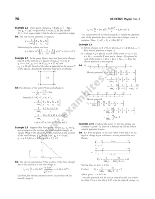

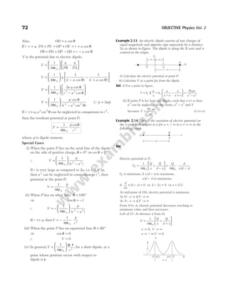

( , , )
2 3 4 2 1 2
1 2 1
x y z = − 1 V
Example 2.17 In uniform electric field, E = −
10 1
NC as
shown in figure, find
(i)V V
A B
− (ii) V V
B C
−
Sol. (i)V V V V
B A A B
> −
, so will be negative.
Further, dAB = ° =
2 60 1
cos m
∴ V V Ed
A B AB
− = −
= −
( 10) (1) = − 10 V
(ii)V V V V
B C B C
> −
, so will be positive.
Further, dBC = 2.0 m
∴ V V
B C
− = (10) (2) = 20 V
Example 2.18 A uniform electric field of 100Vm −1
is
directed at 30° with the positive X-axis as shown in figure.
Find the potential difference,VBA if OA = 2 m and
OB m
= 4 .
Sol. This problem can be solved by both the methods as
discussed below.
Method 1 Electric field in vector form can be written as
E i j
= ° + ° −
( cos $ sin $)
100 30 100 30 1
Vm
= + −
( $ $)
50 3 50 1
i j Vm
A = −
( , , )
2 0 0
m
and B = (0, 4 , 0)
m
∴ V V V
BA B A
= − = − ⋅
∫ E r
A
B
d
= − + ⋅ + +
−
∫ ( $ $) ( $ $ $ )
( , , )
( , , )
50 3 50
2 0 0
0 4 0
i j i j k
m
m
dx dy dz
= − +
[ ]
50 3 50
x y (–2 m, 0, 0)
(0, 4 m, 0)
= − +
100 2 3
( ) V
Electrostatic Potential and Capacitance 73
B
A
C
2 m
2 m
2 m
E
30°
O
A
B
X](https://image.slidesharecdn.com/arihantneetobjectivephysicsvolume2bydcpandey2022edition-230417145135-9bce7664/85/Arihant_NEET_Objective_Physics_Volume_2_By_DC_Pandey_2022_Edition-pdf-84-320.jpg)
![74 OBJECTIVE Physics Vol. 2
Method 2 We can also use,V Ed
=
With the view that,V V V V
A B B A
> −
or will be negative.
Here, d OA OB
AB = ° + °
cos sin
30 30
= × + ×
2
3
2
4
1
2
= +
( )
3 2
∴ V V Ed
B A AB
− = − = − +
100 2 3
( )
Example 2.19 Two points A and B are 2 cm apart and a
uniform electric field E acts along the straight line AB
directed from A to B with E NC
= −
200 1
. A particle of
charge + 10 6
–
C is taken from A to B along AB. Calculate
(i) the force on the charge,
(ii) the potential difference,V V
A B
− and
(iii) the work done on the charge by E.
Sol. (i) Electrostatic force on the charge,
F q E
= = −
( ) ( )
10 200
6
= × −
2 10 4
N
(ii) In uniform electric field,
V Ed
=
∴ Potential difference, V V
A B
− = × × −
200 2 10 2
= 4 V
(iii)W Fs
= cos θ = × × °
− −
( ) ( ) cos
2 10 2 10 0
4 2
= × −
4 10 6
J
Example 2.20 In the uniform electric field shown in figure,
find
(i)V V
A D
− (ii)V V
A C
−
(iii)V V
B D
− (iv)V V
C D
−
Sol. Using the relation,V Ed
= (in uniform E)
where, V = potential difference between the two points
E = magnitude of E
and d = projection of line (joining two points) along E.
(i) V V
A D
− = 0 as d = 0
(ii) V V
A C
− = + =
( ) ( )
20 1 20 V
(iii) V V
B D
− = − = −
( ) ( )
20 1 20 V
(iv) V V
C D
− = − = −
( ) ( )
20 1 20 V
Example 2.21 An electric field E i j
= +
( $ $)
20 30 N/C exists in
the space. If the potential at the origin is taken to be zero,
find the potential at ( , ).
2 2
m m
Sol. We have, E
dV
dr
=
−
, so it can be written in vector form as
dV d
= − ⋅
E r
Note, we can write, E = E E E
x y z
$ $ $
i j k
+ +
and d dx dy dz
r i j k
= + +
$ $ $
Therefore, E r
⋅ = ⋅ + ⋅ + ⋅
d E dx E dy E dz
x y z
In the given question, the z-component of E or the point is not
given. So, we can write
E r
⋅ = ⋅ + ⋅
d E dx E dy
x y
Now, dV d
= − ⋅
E r = − + ⋅ +
( $ $) ( $ $)
20 30
i j i j
dx dy
or dV dx dy
= − −
20 30
Now, we will have to integrate it within limits.
Given,V = 0 when x = 0 and y = 0 (lower limit) and we have
to calculate V. When x = 2 and y = 2 (upper limit)
Therefore, dV dx dy
V
x
x
y
y
0 0
2
0
2
20 30
∫ ∫ ∫
= − ⋅ −
=
=
=
=
or [ ] [ ] [ ]
V x y
V
0 0
2
0
2
20 30
= − −
or V − = − − − −
0 20 2 0 30 2 0
( ) ( )
∴ Potential,V = − − = −
40 60 100 V
E = 20 Vm−1
A B
C
D
1 m
1 m
1. Find the work done by some external force in moving a
charge q = 4 µC from infinity to a point, where electric
potential is104
V.
(a) 4 10 J
2
× −
(b) 2 10 J
2
× −
(c) 8 10 J
2
× −
(d)1 10 J
2
× −
2. Equal charges are given to two spheres of different radii.
The potential will
(a) be more on the smaller sphere
(b) be more on the bigger sphere
(c) be equal on both the spheres
(d) depend on the nature of the materials of the spheres
3. The electric potential at a point in free space due to a charge
Q coulomb is Q ×1011
volts. The electric field at the point is
(a) 4 10
0
20
πε × −
Q Vm 1
(b) 12 10
0
22
πε × −
Q Vm 1
(c) 4 10
0
22
πε × −
Q Vm 1
(d) 12 10
0
20
πε × −
Q Vm 1
4. In an hydrogen atom, the electron revolves around the
nucleus in an orbit of radius 0.53 10 m.
10
× −
Then, the
electrical potential produced by the nucleus at the position
of the electron is
(a) –13.6 V (b) – 27.2 V (c) 27.2 V (d) 13.6 V
5. Three charges 2q q q
, ,
− − are located at the vertices of an
equilateral triangle. At the centre of the triangle,
(a) the field is zero but potential is non-zero
(b) the field is non-zero but potential is zero
(c) Both field and potential are zero
(d) Both field and potential are non-zero
6. In a region of constant potential,
(a) the electric field is uniform
(b) the electric field is zero
(c) there can be no charge inside the region
(d) the electric field shall necessarily change if a charge is
placed outside the region
CHECK POINT 2.1](https://image.slidesharecdn.com/arihantneetobjectivephysicsvolume2bydcpandey2022edition-230417145135-9bce7664/85/Arihant_NEET_Objective_Physics_Volume_2_By_DC_Pandey_2022_Edition-pdf-85-320.jpg)
![Potential at point C
OC r
= , where r b
> .
So, potential at C isV
q q
r
C =
+
ε
1 2
0
4π
(due to inner and outer shell)
Potential at point B
Let OB r
= , where a r b
< < .
As the point B, lies inside the outer shell,
Potential at B due to outer shell isV
q
b
2
2
0
4
=
ε
π
.
The point B lies outside the inner shell, the potential at B,
due to inner shell isV
q
r
1
1
0
4
=
ε
π
.
So, potential at B isV
q
r
q
b
B =
ε
+
ε
1
0
2
0
4 4
π π
Potential at point A
Let OA r
= , such that r a
< . The point A lies inside the outer
shell. So, potential at A, due to outer shell isV
q
b
2
2
0
4
=
ε
π
.
Similarly, potential at A, due to inner shell isV
q
a
1
1
0
4
=
ε
π
.
So, potential at A isV
q
a
q
b
A =
ε
+
ε
1
0
2
0
4 4
π π
.
Example 2.26 A charge Q is distributed over two concentric
hollow spheres of radii r and R r
( )
> such that the surface
densities are equal. Find the potential at any point inside the
smaller sphere.
Sol. Let q and q′ be the charges on the inner and outer sphere.
As surface charge densities are equal.
∴
q
r
q
R
4 4
2 2
π π
=
′
or qR q r
2 2
= ′
Also, q q Q
+ ′ = . This gives q Q q
= − ′
Solving the two equations, we get q
Qr
R r
=
+
2
2 2
, q
QR
R r
′ =
+
2
2 2
Now, potential at the centre is given by
V
q
r
q
R
Q r R
R r
C =
ε
+
′
ε
=
+
ε +
4 4 4
0 0 0
2 2
π π π
( )
( )
This is equal to potential at any point inside the smaller sphere.
Motion of charged particle in
electric field
Consider a charged particle having charge q and mass m is
initially at rest in an electric field of strength E. The particle
will experience an electric force which causes its motion.
The force experienced by the charged particle is F, where
F qE
=
∴ Acceleration produced by this force is a = =
F
m
qE
m
…(i)
Suppose at point A particle is at rest and after some time t,
it reaches the point B and attains velocity v.
∴ v at
=
If potential difference between A and B be ∆V and the
distance between them is d, then v
qEt
m
q V
m
= =
2 ∆
… (ii)
As, momentum, p mv
=
∴ p m
qEt
m
=
= qEt [from Eq. (ii)]
or p m
q V
m
mq V
= × =
2
2
∆
∆
Kinetic energy of a charged particle
Kinetic energy gained by the particle in time t,
K mv m
qEt
m
= =
1
2
1
2
2
2
[from Eq. (ii)]
=
q E t
m
2 2 2
2
or K m
q V
m
q V
= × =
1
2
2 ∆
∆
Electrostatic Potential and Capacitance 79
O
a
b
r
q1
q2
B
Fig. 2.21
O
a
b
r
q1
q2
A
Fig. 2.22
O
a
b
r
q1
q2
C
Fig. 2.20
d
A B
E
Fig. 2.23](https://image.slidesharecdn.com/arihantneetobjectivephysicsvolume2bydcpandey2022edition-230417145135-9bce7664/85/Arihant_NEET_Objective_Physics_Volume_2_By_DC_Pandey_2022_Edition-pdf-90-320.jpg)
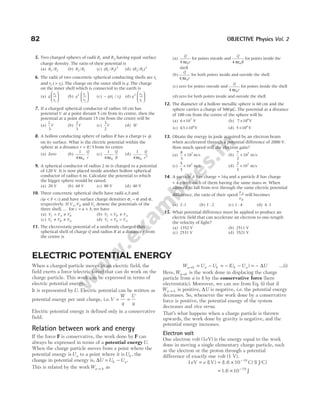
![Example 2.31 A spherical oil drop of radius 10 4
−
cm has a
total charge equivalent to 40 electrons. Calculate the energy
that would be required to place an additional electron on the
drop.
Sol. Initial charge on the oil drop, q = × × −
40 10 19
1.6
= × −
64 10 19
C
Potential of the oil drop =
ε
q
r
4 0
π
=
× × ×
= ×
−
−
−
9 10 64 10
10
576 10
9 19
6
4
V
Now, energy required = work done in bringing an electron
from infinity to a point of potential.
As, potential =
work
charge
∴ Work = Potential × Charge = × × ×
− −
576 10 10
4 19
1.6
= × −
921.6 J
10 23
Example 2.32 A uniform electric field E0 is directed along
positive y-direction. Find the change in electric potential
energy of a positive test charge q0 when it is displaced in the
field from y a
i = to y a
f = 2 along the Y-axis.
Sol. Electrostatic force on the test charge,
F q E
e = 0 0 (along positive y-direction)
∴W U
i f
− = – ∆ or ∆U Wi f
= −
– = – [ ( – )]
q E a a
0 0 2 = – q E a
0 0
Note Here, work done by electrostatic force is positive. Hence, the
potential energy is decreasing.
Example 2.33 Find the change in electric potential energy,
∆U as a charge of 2.20 × −
10 6
C, moves from a point A to
point B, given that the change in electric potential between
these points is ∆V V V V
B A
= − = 24.0 .
Sol. As, ∆
∆
V
U
q
=
0
, where ∆U is change in potential energy
∴ ∆ ∆
U q V
= = × = ×
− −
0
6 5
10 10
(2.20 ) (24.0) 5.28 J
Example 2.34 A charge is moved in an electric field of a
fixed charge distribution from point A to another point B
slowly. The work done by external agent in doing so, is
100 J. What is the work done by the electric field of the
charge distribution as the charge moves from A to B?
Sol. Work done,W U U U
B A
ext J
= ∆ = − = 100
As, F F
ext = − E for the charge to move slowly, so
W W
E = − = −
ext J
100
Exmple 2.35 Three point charges of 0.1 C each are placed at
the corners of an equilateral triangle with side 1 m. If this
system is supplied energy at the rate of 1 kW, how much
time will be required to move one of the charges to the
mid-point of the line joining the two others?
Sol.
U1
0
1
4 1
3
=
ε
×
×
π
0.1 0.1
= × × × = ×
−
9 10 3 10 27 10
9 2 7
J
U2
0
1
4
2
1
=
ε
×
× +
×
π
0.1 0.1
0.5
0.1 0.1
= × ×
9 109
0.05 = ×
45 107
J
W U U
1 2 2 1
7
18 10
→ = − = × J
Rate at which energy is supplied is given by
P
W
t
=
∴ t
W
P
= =
×
= × =
18 10
10
18 10 50
7
3
4
s h
Potential energy of a system
of charges
The potential energy for a system of two point charges and
for a collection of more than two charges are given below.
1. Potential energy for a system of two
point charges
Potential energy of the system of two charges q1 and q 2
will be the work done to bring them from infinity to point
A and point B, respectively.
Work done to bring charge q1 from infinity to point A,
W1 0
=
Work done to bring charge q 2 from infinity to point B,
W q V V
B A
2 2
= −
( )
As, W q
q
r
2 2
0
1
1
4
= × ⋅
πε
Now, potential energy of the system of charges q1 and q 2,
U W W
= +
1 2
U
q q
r
= ⋅
1
4 0
1 2
πε
Electrostatic Potential and Capacitance 83
E0
q E
0 0
+ q0
0.1 C
0.1 C
0.1 C
1 m 1 m
1 m
(1)
0.5 m 0.5 m
0.1 C 0.1 C 0.1 C
(2)](https://image.slidesharecdn.com/arihantneetobjectivephysicsvolume2bydcpandey2022edition-230417145135-9bce7664/85/Arihant_NEET_Objective_Physics_Volume_2_By_DC_Pandey_2022_Edition-pdf-94-320.jpg)
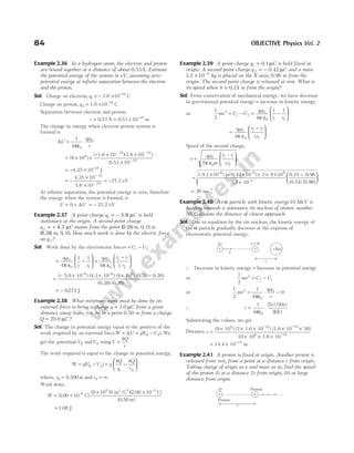
![Sol. The proton moves away under electrostatic repulsion.
As there is no external force, Wext = 0
⇒ ∆ ∆
KE PE
+ = 0
⇒
1
2
0
2
mv U U
f i
+ − =
( )
(i) We have, U
e
r
f =
ε
2
0
4 2
π ( )
, and U
e
r
i =
ε
2
0
4π ( )
∴
1
2 4 2
2
2
0
mv
e
r
=
ε
π ( )
or speed of the proton, v
e
rm
=
ε
2
0
4π
(ii) We have,Uf = 0,U
e
r
i =
ε
2
0
4π
∴
1
2 4
2
2
0
mv
e
r
=
ε
π
Speed of the proton, v
e
rm
=
ε
2
4
2
0
π
Example 2.42 A uniformly charged thin ring has radius
10 0
. cm and total charge + 12.0 nC. An electron is placed
on the ring’s axis at a distance 25.0 cm from the centre of
the ring and is constrained to stay on the axis of the ring.
When the electron is released from rest, then
(i) describe the subsequent motion of the electron.
(ii) find the speed of the electron when it reaches the centre of
the ring.
Sol. (i) The electron will be attracted towards the centre C of
the ring. At C net force is zero, but on reaching C,
electron has some kinetic energy and due to inertia it
crosses C, but on the other side it is further attracted
towards C. Hence, motion of electron is oscillatory about
point C.
(ii) As the electron approaches C, its speed (hence, kinetic
energy) increases due to force of attraction towards the
centre C. This increase in kinetic energy is equal to
change in electrostatic potential energy. Thus,
1
2
2
mv U U
i f
= −
⇒
1
2
2
mv = − = − −
U U e V V
P C P C
( ) [ ] …(i)
Here, V is the potential due to ring.
V
q
r
P = ⋅
1
4 0
πε
(where, q = charge on ring)
=
× ×
+ ×
=
−
−
( ) ( )
( ( ) ( ) )
9 10 12 10
10 25 10
401
9 9
2 2 2
V
V
q
R
C = ⋅
1
4 0
π ε
=
× ×
×
−
−
( ) ( )
9 10 12 10
10 10
9 9
2
= 1080 V
Substituting the proper values in Eq. (i), we get
1
2
9 1 10 1 6 10 401 1080
19
(–
–31 2
× × × = × −
−
. . ) ( )
v
∴ Speed of the electron, v = × −
15.45 106 1
ms
2. Potential energy for a collection of
more than two charges
The potential energy of a system of n charges is given by
U
K q q
r
i j
ij
i j
i j
n
=
≠
∑
2 ,
here, K =
1
4 0
πε
The factor of 1/2 is applied only with the summation sign
because on expanding the summation, each pair is
counted twice. It is reqresented byU.
For example, electric potential energy of four point
charges q q q
1 2 3
, , and q 4 would be given by
U
q q
r
q q
r
q q
r
q q
r
q q
r
q q
= + + + + +
1
4 0
4 3
43
4 2
42
4 1
41
3 2
32
3 1
31
2
πε
1
21
r
Here, all the charges are to be substituted with sign.
Example 2.43 Three point charges of 1 2
C C
, and 3 C are
placed at the corners of an equilateral triangle of side 1m.
Calculate the work required to move these charges to the
corners of a smaller equilateral triangle of side 0 5
. m.
Sol. Work done = U U
f i
–
Electrostatic Potential and Capacitance 85
+
+
+
+
+
+
+
+
+
+
+
+
+
+
+
+
+
R
C
r
P
e–
q2
q3
q1
q4
Fig. 2.27 System of four charges
0
.
5
m
0
.
5
m
1m
A′
B′ C′
1m
1m
B C
A q1
q2 q3
q2 q3
q1
0.5 m
0.5 m](https://image.slidesharecdn.com/arihantneetobjectivephysicsvolume2bydcpandey2022edition-230417145135-9bce7664/85/Arihant_NEET_Objective_Physics_Volume_2_By_DC_Pandey_2022_Edition-pdf-96-320.jpg)
![= −
1
4
1 1
0
π ε r r
f i
[ ]
q q q q q q
3 2 3 1 2 1
+ +
= × −
+ +
9 10
1
0 5
1
1
3 2 3 1 2 1
9
.
[( )( ) ( )( ) ( )( )]
= ×
99 109
J
Example 2.44 Find the electric potential energy of the system
of charges.
Sol. Number of pairs = 3
The electric potential energy for a system of charges is given by
U
q q
r
q q
r
q q
r
=
ε
+ +
1
4 0
1 2 2 3 1 3
π
On putting the values, we get
U
Q Q
d
Q Q
d
Q Q
d
=
ε
⋅
⋅
+
⋅
+
⋅
1
4
15
3
8
4
15 8
5
0
π
=
ε
⋅
1
4
31
0
2
π
Q
d
Example 2.45 Four charges q C
1 1
= µ , q C
2 2
= µ ,
q C
3 3
= − µ and q C
4 4
= µ are kept on the vertices of a
square of side 1 m. Find the electric potential energy of this
system of charges.
Sol. We have, r r r r
41 43 32 21 1
= = = = m
and r r
42 31
2 2
1 1 2
= = + =
( ) ( ) m
Potential energy of a system of three charges,
U
q q
r
q q
r
q q
r
q q
r
q q
r
q q
=
ε
+ + + + +
1
4 0
4 3
43
4 2
42
4 1
41
3 2
32
3 1
31
2
π
1
21
r
U = × − −
( . )( )( )
9 0 10 10 10
9 6 6
(4)( 3)
1
(4)(2)
2
(4)(1)
1
( 3)(2)
1
( 3)(1)
2
−
+ + +
−
+
− (2)(1)
1
+
= × − +
−
( . )
9 0 10 12
5
2
3
= − × −
7.62 10 J
2
Note Here, negative sign of U implies that positive work has been done
by electrostatic forces in assembling these charges at respective
distances from infinity.
Example 2.46 Two point charges are located on the X-axis,
q C
1 1
= − µ at x = 0 and q C
2 1
= + µ at x m
= 1 .
(i) Find the work that must be done by an external force to bring a
third point charge q C
3 1
= + µ from infinity to x m
= 2 .
(ii) Find the total potential energy of the system of three charges.
Sol. (i) The work that must be done on q3 by an external force
is equal to the difference of potential energy ∆U when
the charge is at x = 2m and the potential energy when it
is at infinity.
∴ W U U U
f i
= = −
∆ = + +
1
4 0
3 2
32
3 1
31
2 1
21
πε
q q
r
q q
r
q q
r
f f f
( ) ( ) ( )
− + +
1
4 0
3 2
32
3 1
31
2 1
21
πε
q q
r
q q
r
q q
r
i i i
( ) ( ) ( )
Here, ( ) ( )
r r
i f
21 21
= and ( ) ( )
r r
i i
32 31
= = ∞
∴ W
q q
r
q q
r
f f
= +
1
4 0
3 2
32
3 1
31
πε ( ) ( )
Substituting the values, we get
W = × +
−
−
(9.0 10 ) (10 )
(1) (1)
(1.0)
(1) ( 1)
(2.0
9 12
)
= ×
4.5 10 J
–3
(ii) The total potential energy of the three charges is
given by
U
q q
r
q q
r
q q
r
= + +
1
4 0
3 2
32
3 1
31
2 1
21
πε
= × +
−
+
(9.0 10 )
(1) (1)
(1.0)
(1) ( 1)
(2.0)
(1) (
9 −
−
1)
(1.0)
(10 )
12
= − × −
4.5 10 J
3
Example 2.47 Two point charges q q C
1 2 2
= = µ are fixed
at x m
1 3
= + and x m
2 3
= – as shown in figure. A third
particle of mass 1 g and charge q C
3 4
= – µ are released
from rest at y m
= 4 0
. . Find the speed of the particle as it
reaches the origin.
Sol. Here, the charge q3 is attracted towards q1 and q2 both. So,
the net force on q3 is towards origin.
86 OBJECTIVE Physics Vol. 2
1 m
1 m
q1 q2
q3
q4
1 m
1 m
15Q
8Q
Q
4d
3d
5d
y
x
q2 q1
x1 = 3 m
x2 = –3 m
O
q3 y = 4 m
y
x
q2 q1
O
q3
Fnet](https://image.slidesharecdn.com/arihantneetobjectivephysicsvolume2bydcpandey2022edition-230417145135-9bce7664/85/Arihant_NEET_Objective_Physics_Volume_2_By_DC_Pandey_2022_Edition-pdf-97-320.jpg)
![By this force, charge is accelerated towards origin, but this
acceleration is not constant.
So, to obtain the speed of particle at origin by kinematics, we
have to find first the acceleration at same intermediate
position and then will have to integrate it with proper limits.
On the other hand, it is easy to use principle of conservation
of energy as the forces are conservative.
Let v be the speed of particle at origin. From conservation of
mechanical energy,
U K U K
i i f f
+ = +
or
1
4
0
0
3 2
32
3 1
31
2 1
21
πε
q q
r
q q
r
q q
r
i i i
( ) ( ) ( )
+ +
+
= + +
+
1
4
1
2
0
3 2
32
3 1
31
2 1
21
2
πε
q q
r
q q
r
q q
r
mv
f f f
( ) ( ) ( )
Here, ( ) ( )
r r
i f
21 21
=
Substituting the proper values, we have
(9.0 10 )
( 4) (2)
(5.0)
( 4) (2)
(5.0)
9
×
−
+
−
× −
10 12
= ×
−
+
−
(9.0 10 )
( 4) (2)
(3.0)
( 4) (2)
(3.0)
9
× + × ×
− −
10
1
2
10
12 3 2
v
∴ ( ) ( )
–
9 10
16
5
9 10
16
3
1
2
10
3 3 3 2
× −
= × −
+ × ×
− −
v
( ) ( )
9 10 16
2
15
1
2
10
3 3 2
×
= × ×
− −
v
∴ v = −
6.2 ms 1
Potential energy in an external field
Here, mainly two situations are possible.
Potential energy of a single charge in external
field Potential energy of a single charge q at a point with
position vector r in an external field = ⋅
q V r
( )
where,V r
( ) is the potential at a point (i.e. position vector r)
due to external electric field E.
Potential energy of a system of two charges in an
external field Consider two charges q1 and q 2 kept in an
external field E at A and B.
Then, potential energy of a system is given by
U q V r q V r
q q
r
= + +
1 1 2 2
1 2
0 12
4
( ) ( )
πε
where, r1 and r2 are the position vector of point A and B
respectively,
V r
( )
1 is potential at r1 due to the external field
andV r
( )
2 is potential at r2 due to the external field.
Potential energy of a dipole
in a uniform electric field
The work done in rotating the dipole through a small angle
dθ.
dW d pE
= = −
τ θ sinθ θ
d
Suppose initially dipole is kept in a uniform electric field
at angle θ1. Now, to turn it through an angle θ2 (with the
field). Then, work done
W pE d
= ∫ sinθ θ
θ
θ
1
2
W pE
= − [cos cos ]
θ θ
2 1
−
If θ1 0
= ° and θ θ
2 = , i.e. initially dipole is kept along the
field and then it turns through θ, so work done,
W pE
= −
( cos )
1 θ
Potential energy of dipole is defined as work done in
rotating a dipole from a direction perpendicular to the field
to the given direction.
If the dipole is rotated by an angle θ1 90
= ° to θ θ
2 = ,
then potential energy is given by
U pE
= ° −
(cos cos )
90 θ
= − pE cosθ = − ⋅
p E
Example 2.48 When an electric dipole is placed in a uniform
electric field making angle θ with electric field, it
experiences a torque τ. Calculate the minimum work done in
changing the orientation to 2θ.
Sol. τ θ
= pE sin ⇒ pE =
τ
θ
sin
W U pE pE
= = − +
∆ cos cos
θ θ
2 1
⇒ W pE
= −
[cos cos ]
θ θ
2
⇒ W = −
τ
θ
θ θ
sin
[cos cos ]
2
Equilibrium of dipole
(i) Work done, when θ = °
0
U pE pE
= − ° = −
cos 0
Thus, the potential energy of a dipole is minimum
when its dipole moment is parallel to the external
field. This is the position of stable equilibrium.
(ii) When θ = °
180
U pE pE
= − ° = +
cos180
Thus, the potential energy of a dipole is maximum
when its dipole moment is antiparallel to the
external field. This is the position of unstable
equilibrium.
Electrostatic Potential and Capacitance 87](https://image.slidesharecdn.com/arihantneetobjectivephysicsvolume2bydcpandey2022edition-230417145135-9bce7664/85/Arihant_NEET_Objective_Physics_Volume_2_By_DC_Pandey_2022_Edition-pdf-98-320.jpg)
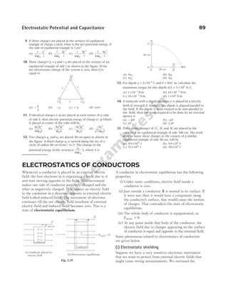
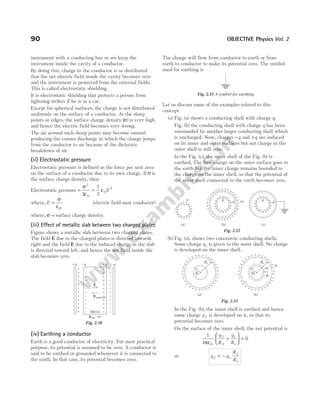
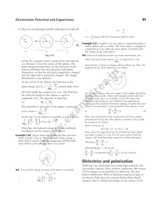
![where, χ is a constant of proportionality and is called
electric susceptibility of the dielectric slab. It is a
dimensionless constant.
Note
1. For vacuum, χ = 0 2. K = +
1 χ
Dielectric strength
The maximum electric field that a dielectric can withstand
without breakdown is called its dielectric strength.
Its SI unit is Vm 1
−
and its practical unit is kV(mm) 1
−
.
For air it is about 3 106
× Vm−1
.
Capacitors and capacitance
A capacitor is a device which is used to store electric
charge or potential energy. It is made up of two isolated
conductors carrying equal and opposite charges placed at
small separation.
The space between the conductors may be vacuum or an
insulating material. Capacitor is represented as
Capacitance of a conductor
When a charge q is given to a conductor, it spreads over
the outer surface of the conductor. The whole conductor
comes to the same potential (say V). This potential V is
directly proportional to the charge q, i.e.
V q
∝
q CV
=
or C
q
V
=
This C is constant of proportionality and is called the
capacitance of the conductor.
The SI unit of capacitance is called farad (F). One farad is
equal to coulomb per volt (1 C /V).
∴ 1 farad (1F) = 1 coulomb/volt (1C/V)
Its dimensional formula is [ML T A ].
2 4 2
−
Capacitance C depends on the shape, size and separation
of the system of two conductors and is independent of the
charge given to the body.
Example 2.52 A capacitor of 0.75 µF is charged to a voltage
of 16 V. What is the magnitude of the charge on each plate
of the capacitor?
Sol. Using q CV
= , we get
q CV
= = × = ×
− −
(0.75 F V) 1.2 C
10 16 10
6 5
) (
Capacitance of an isolated spherical
conductor
When a charge q is given to a spherical conductor of
radius R, the potential on it is
V
q
R
= ⋅
1
4 0
πε
From this expression, we find that
q
V
R C
= =
4πε0
Thus, capacitance of the spherical conductor is
C R
= 4 0
πε
From this expression, we can draw the following
conclusions
(i) C R
∝ or C depends on R only. Which we have
already stated that C depends on the dimensions of
the conductor. Moreover if two conductors have radii
R1 and R2, then
C
C
R
R
1
2
1
2
=
Electrostatic Potential and Capacitance 93
+
+
+
+
+
–
–
–
–
–
+q
Fig. 2.38
or
Fig. 2.39
V
+
+
+
+
+
+
+
+
+
+
+
+
+
+
+
q
Fig. 2.40
+
+
+
+ +
+
+
+
+
+
+
+
+
+
+
+
q
R
Fig. 2.41 Spherical conductor](https://image.slidesharecdn.com/arihantneetobjectivephysicsvolume2bydcpandey2022edition-230417145135-9bce7664/85/Arihant_NEET_Objective_Physics_Volume_2_By_DC_Pandey_2022_Edition-pdf-104-320.jpg)
![(ii) Earth is also a spherical conductor of radius
R = ×
6.4 10 m
6
. The capacity of earth is therefore,
C =
×
×
1
9 109
(6.4 10 )
6
≈ ×
711 10 F
–6
or C = 711µF
From here, we can see that farad is a large unit. As
capacity of such a huge conductor is only 711µF.
Capacity of a spherical conductor enclosed
by an earthed concentric spherical shell
Let a system two concentric conducting spheres of radii a
and b, where a less than b. Inner sphere is given charge q
while outer sphere is earthed. Potential difference
between the spheres is given by
V
q
a b
= −
4
1 1
0
πε
…(i)
Hence, the capacitance of this system will be
C
q
V
=
or C
ab
b a
=
−
4 0
πε [from Eq. (i)]
Example 2.53 A sphere of radius 0.03 m is suspended within
a hollow sphere of radius 0.05 m. If the inner sphere is
charged to a potential of 1500 V and outer sphere is
earthed, find the capacitance and the charge on the inner
sphere.
Sol. Here, a = 0.03 m, b = 0.05 m andV = 1500 V
The capacitance of the air-filled spherical capacitor is
C
ab
b a
=
ε
−
4 0
π
( )
=
×
× × −
0.03 0.05
(0.05 0.03
9 109
)
= × =
−
8.33 F 8.33 pF
10 12
Charge, q CV
= = × ×
−
8.33 10 1500
12
= × −
1.25 10 C
8
Example 2.54 The thickness of air layer between the two
coatings of a spherical capacitor is 2 cm. The capacitor has
the same capacitance as the sphere of 1.2 m diameter. Find
the radii of its surfaces.
Sol. Here,
4
4
0
0
π
π
ε
−
= ε
ab
b a
R or
ab
b a
R
−
=
Now, b a
− = 2 cm and R = =
1.2
m
2
60 cm
∴
ab
2
60
=
or ab = 120
( ) ( )
b a b a ab
+ = − +
2 2
4 = + × =
2 4 120 484
2
or b a
+ = 22
or 2 22
+ + =
a a ( )
Qb a
− = 2 cm
∴ a = 10 cm and b = 12 cm
Cylindrical capacitor
Cylindrical capacitor consists of two co-axial cylinders of
radii a and b (a < b), inner cylinder is given charge +q
while outer cylinder is earthed.
Common length of the cylinders is l, then capacity of a
cylindrical capacitor is given by
C
l
b a
e
=
2 0
πε
log ( / )
Parallel plate capacitor
A parallel plate air capacitor consists of two parallel
metallic plates separated by a small distance.
Suppose the area of each plate is A and the separation
between the two plates is d. Also assume that the space
between the plates contains vacuum. Suppose, the charge
density on each of these surfaces has a magnitude σ = q A
/ .
94 OBJECTIVE Physics Vol. 2
a
b
–q
+q
Fig. 2.42
+
+
+
+
+
+
+
–
–
–
–
–
–
–
–
–
–
–
–
–
–
–
–
+
+
+
+
+
+
+
Charge density –λ
Charge density +λ
b
a
Fig. 2.43
(a) (b)
or
+q –q
+ – q
+
+
+
+
+
+
+
+
+
+
–
–
–
–
–
–
–
–
–
–
–q
+ –
+ –
+ –
+ –
+ –
+ –
+ –
Fig. 2.44](https://image.slidesharecdn.com/arihantneetobjectivephysicsvolume2bydcpandey2022edition-230417145135-9bce7664/85/Arihant_NEET_Objective_Physics_Volume_2_By_DC_Pandey_2022_Edition-pdf-105-320.jpg)
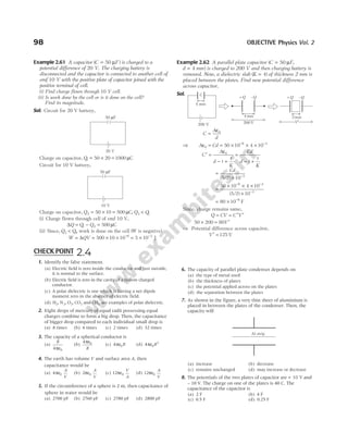
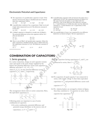
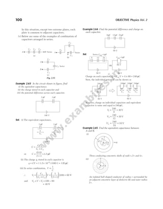
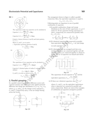
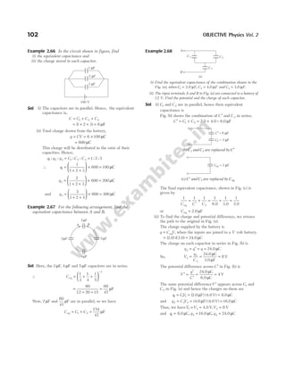
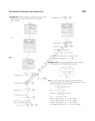
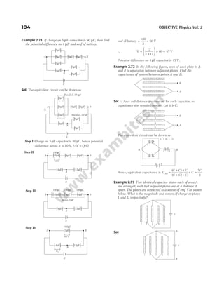
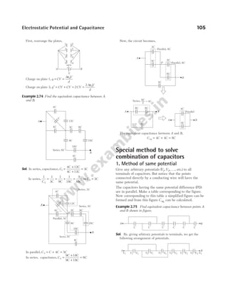
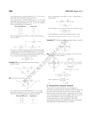
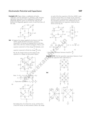
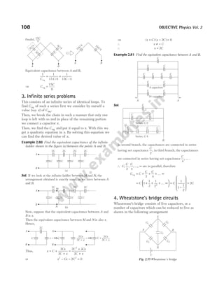
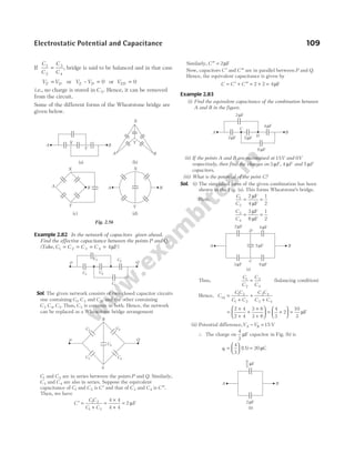
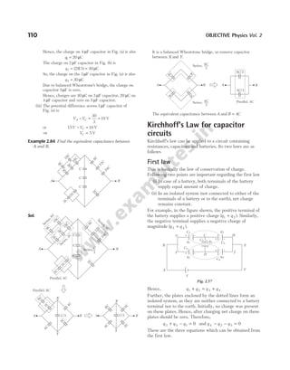
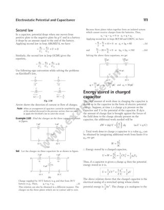
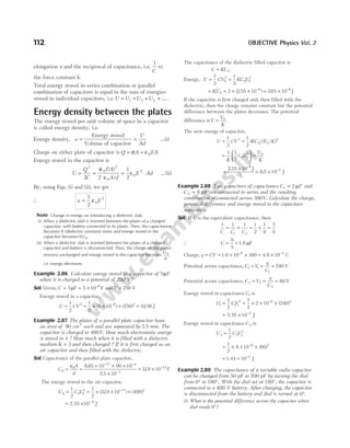
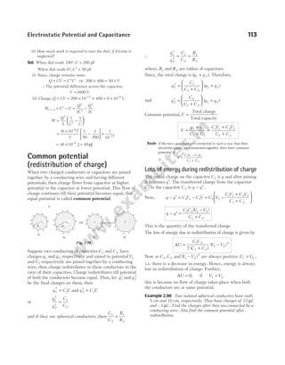
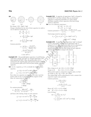
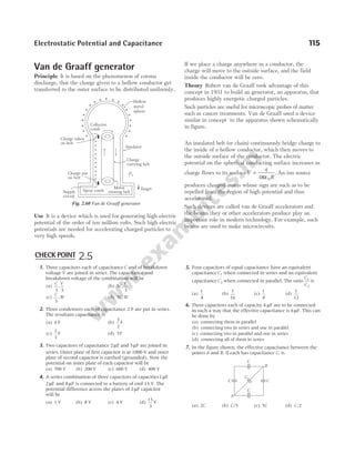
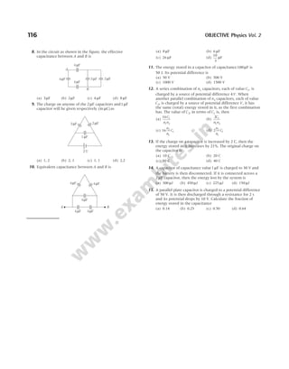
![(A) Taking it together
Assorted questions of the chapter for advanced level practice
1 Angle between equipotential surface and lines of
force is
(a) zero (b) 180°
(c) 90° (d) 45°
2 From a point charge there is a fixed point A. At that
point there is an electric field of 500 V/m and
potential of 3000 V. Then, the distance of point A
from the point charge is
(a) 6 m (b) 12 m
(c) 36 m (d) 144 m
3 A charge of 5 C is given a displacement of 0.5 m.
The work done in the process is 10 J. The potential
difference between the two points will be
(a) 2 V (b) 0.25 V
(c) 1 V (d) 25 V
4 An electron enters in higher potential regionV2 from
lower potential regionV1, then its velocity will
(a) increase
(b) change in direction but not in magnitude
(c) not change in direction of field
(d) change in direction perpendicular to field
5 When the separation between two charges is
increased, the electric potential energy of the
charges
(a) increases (b) decreases
(c) remains the same (d) may increase or decrease
6 If a positive charge is shifted from a low potential
region to a high potential region, then the electric
potential energy
(a) increases (b) decreases
(c) remains the same (d) may increase or decrease
7 The work done in carrying a charge of 5 µC from a
point A to a point B in an electric field is 10 mJ.
Then, potential difference ( )
V V
B A
− is
(a) + 2 kV (b) – 2 kV
(c) + 200 kV (d) – 200 kV
8 The capacitance of a capacitor does not depend on
the
(a) medium between the plates
(b) size of the plates
(c) charges on the plates
(d) separation between the plates
9 In a charged capacitor, the energy resides in
(a) the positive charges
(b) Both the positive and negative charges
(c) the field between the plates
(d) around the edge of the capacitor plates
10 Which of the following is not true?
(a) For a point charge, the electrostatic potential varies as 1/r
(b) For a dipole, the potential depends on the position
vector and dipole moment vector
(c) The electric dipole potential varies as 1/r at large
distance
(d) For a point charge, the electrostatic field varies as 1/r2
11 The energy stored in a condenser is in the form of
(a) kinetic energy (b) potential energy
(c) elastic energy (d) magnetic energy
12 The potential energy of a charged parallel plate
capacitor isU0 . If a slab of dielectric constant K is
inserted between the plates, then the new potential
energy will be
(a)
U
K
0
(b) U K
0
2
(c)
U
K
0
2
(d)U0
2
13 A charge Q is placed at the origin. The electric
potential due to this charge at a given point in space
isV. The work done by an external force in bringing
another charge q from infinity to the point is
(a)
V
q
(b) Vq (c) V q
+ (d) V
14 The force between the plates of a parallel plate
capacitor of capacitance C and distance of separation
of the plates d with a potential difference V between
the plates, is
(a)
CV
d
2
2
(b)
C V
d
2 2
2
2
(c)
C V
d
2 2
2
(d)
V d
C
2
15 A positively charged particle is released from rest in
a uniform electric field. The electric potential energy
of the charge [NCERT Exemplar]
(a) remains a constant because the electric field is uniform
(b) increases because the charge moves along the electric
field
(c) decreases because the charge moves along the electric
field
(d) decreases because the charge moves opposite to the
electric field
Exercises
Chapter](https://image.slidesharecdn.com/arihantneetobjectivephysicsvolume2bydcpandey2022edition-230417145135-9bce7664/85/Arihant_NEET_Objective_Physics_Volume_2_By_DC_Pandey_2022_Edition-pdf-128-320.jpg)
![16 Equipotentials at a great distance from a collection
of charges whose total sum is not zero are
approximately [NCERT Exemplar]
(a) spheres (b) planes
(c) paraboloids (d) ellipsoids
17 An electron enters in high potential regionV2 from
lower potential regionV1, then its velocity
(a) will increase
(b) will change in direction but not in magnitude
(c) No change in direction of field
(d) No change in direction perpendicular to field
18 The capacitance of a metallic sphere is1µF, if its
radius is nearly
(a) 9 km (b) 10 m
(c) 1.11 m (d) 1.11 cm
19 The unit of electric field is not equivalent to
(a) N/C (b) J/C
(c) V/m (d) J/C-m
20 Electric potential at a point x from the centre inside
a conducting sphere of radius R and carrying charge
Q is
(a)
1
4 0
πε
Q
R
(b)
1
4 0
πε
Q
x
(c)
1
4 0
πε
xQ (d) zero
21 If a charged spherical conductor of radius 5 cm has
potential V at a point distant 5 cm from its centre,
then the potential at a point distant 30 cm from the
centre will be
(a)
1
3
V (b)
1
6
V (c)
3
2
V (d) 3V
22 Two plates are at potentials − 10 V and + 30 V. If
the separation between the plates be 2 cm. The
electric field between them is
(a) 2000 V/m (b) 1000 V/m
(c) 500 V/m (d) 3000 V/m
23 The potential at a point due to an electric dipole will
be maximum and minimum when the angles
between the axis of the dipole and the line joining
the point to the dipole are respectively
(a) 90° and 180° (b) 0° and 90°
(c) 90° and 0° (d) 0° and 180°
24 An electric dipole when placed in a uniform electric
field E will have minimum potential energy if the
dipole moment makes the following angle with E
(a) π (b) π /2
(c) zero (d) 3π /2
25 How much kinetic energy will be gained by an
α-particle in going from a point at 70 V to another
point at 50 V?
(a) 40 eV (b) 40 keV (c) 40 MeV (d) 0 eV
26 A charged particle of mass m and charge q is
released from rest in an electric field of constant
magnitude E. The KE of the particle after time t is
(a)
Eq m
t
2
2
2
(b)
2 2 2
E t
mq
(c)
E q t
m
2 2 2
2
(d)
Eqm
t
2
27 Two positive charges12 µC and 8 µC are 10 cm
apart. The work done in bringing them 4 cm closer
is
(a) 5.8 J (b) 5.8 eV
(c) 13 J (d) 13 eV
28 The capacitance of the earth, viewed as a spherical
conductor of radius 6408 km is
(a) 980 µF (b) 1424 µF
(c) 712 µF (d) 356 µF
29 A thin metal plate P is inserted between the plates
of a parallel plate capacitor of capacitance C in such
a way that its edges touch the two plates. The
capacitance now becomes
(a) C/2 (b) 2C (c) zero (d) ∞
30 A capacitor of capacity C has charge Q and stored
energy is W. If the charge is increased to 2Q, then
the stored energy will be
(a) 2W (b) W/2 (c) 4W (d) W/4
31 A 2 µF capacitor is charged to 100 V and then its
plates are connected by a conducting wire. The heat
produced is
(a) 1 J (b) 0.1 J (c) 0.01 J (d) 0.001 J
32 If there are n capacitors in parallel connected toV
volt source, then the energy stored is equal to
(a) nCV 2
(b)
1
2
2
nCV (c)
CV
n
2
(d)
1
2
2
n
CV
33 A variable condenser is permanently connected to a
100 V battery. If the capacity is changed from 2 µF
to 10 µF, then change in energy is equal to
(a) 2 10 2
× −
J (b) 2 5 10 2
. × −
J
(c) 3 5 10 2
. × −
J (d) 4 10 2
× −
J
34 Two condensers of capacity 0.3 µF and 0.6 µF
respectively are connected in series. The
combination is connected across a potential of 6 V.
The ratio of energies stored by the condensers will
be
(a)
1
2
(b) 2 (c)
1
4
(d) 4
35 A capacitor of capacity C1, is charged by connecting
it across a battery of emfV0 . The battery is then
removed and the capacitor is connected in parallel
with an uncharged capacitor of capacity C 2. The
potential difference across this combination is
118 OBJECTIVE Physics Vol. 2](https://image.slidesharecdn.com/arihantneetobjectivephysicsvolume2bydcpandey2022edition-230417145135-9bce7664/85/Arihant_NEET_Objective_Physics_Volume_2_By_DC_Pandey_2022_Edition-pdf-129-320.jpg)
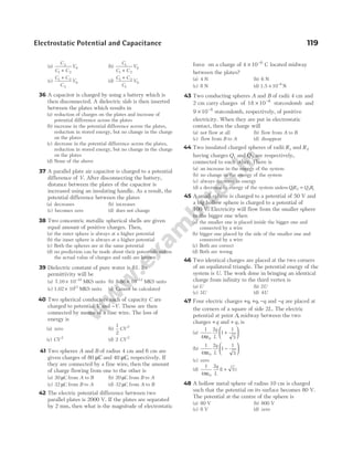
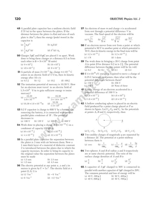
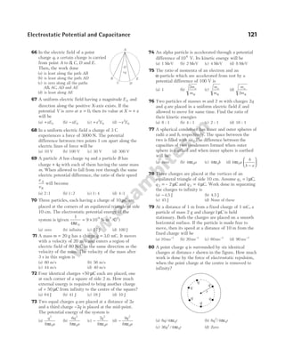
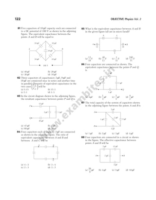
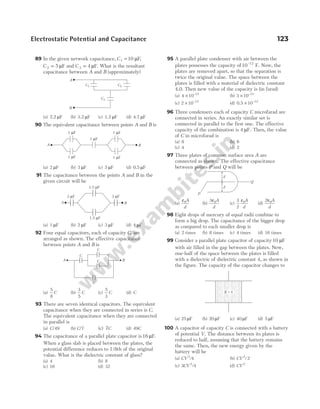
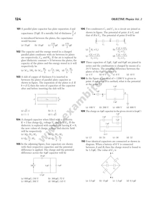
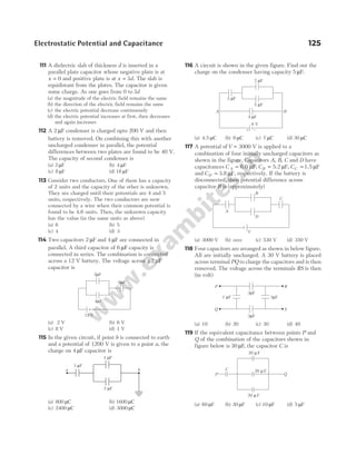
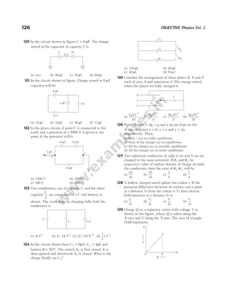
![(a) capacitance
(b) capacitive reactance
(c) electric field between the plates
(d) energy stored in the capacitor
130 How many1µF capacitors must be connected in
parallel to store a charge of 1 C with a potential of
110 V across the capacitors?
(a) 990 (b) 900 (c) 9090 (d) 909
131 In the figure below, the capacitance of each
capacitor is 3µF. The effective capacitance between
points A and B is
(a)
3
4
µF (b) 3 µF (c) 6 µF (d) 5 µF
132 A 500 µF capacitor is charged at the steady rate of
100 µC s
/ . How long will it take to raise the potential
difference between the plates of the capacitor to
10 V?
(a) 5 s (b) 10 s (c) 50 s (d) 100 s
133 A ball of mass 1 g and charge10 8
−
C moves from a
point A, where potential is 600 V to the point B
where potential is zero. Velocity of the ball at the
point B is 20 cms−1
. The velocity of the ball at the
point A will be
(a) 22.8 cms−1
(b) 228 cms−1
(c) 16.8 ms−1
(d) 168 ms−1
134 Three capacitors of capacitances1µF, 2 µF and 4µF
are connected first in a series combination, and then
in parallel combination. The ratio of their
equivalent capacitances will be
(a) 2 49
: (b) 49 2
: (c) 4 49
: (d) 49 4
:
135 An electron moving with the speed 5 106
× m/s is
shooted parallel to the electric field of intensity
1 103
× N/C. Field is responsible for the retardation
of motion of electron. Now evaluate the distance
travelled by the electron before coming to rest for an
instant (mass of e = × −
9 10 31
kg, charge
= × −
1.6 10 19
C).
(a) 7 m (b) 0.7 mm
(c) 7 cm (d) 0.7 cm
136 The electric potential at a point ( , , )
x y z is given by
V x y xz
= − − +
2 3
4
The electric field E at that point is
(a) E i j k
= + + +
$ ( ) $ $
2 3
3 2 2
xy z x xz
(b) E i j k
= + + + −
$ $ ( ) $ ( )
2 3
2 2 2
xy x y xz y
(c) E i j k
= + +
$ $ $
z xyz z
3 2
(d) E i j k
= − + +
$ ( ) $ $
2 3
3 2 2
xy z xy z x
137 Three charges − +
q Q
, and −q are placed in a straight
line as shown.
If the total potential energy of the system is zero,
then the ratio
q
Q
is
(a) 2 (b) 5.5 (c) 4 (d) 1.5
138 The mutual electrostatic potential energy between
two protons which are at a distance of 9 10 15
× −
m,
in 92
235
U nucleus is
(a) 1.56 10 14
× −
J (b) 5.5 10 14
× −
J
(c) 2.56 10 14
× −
J (d) 4.56 10 14
× −
J
139 Three capacitor of capacitance C (µF) are connected
in parallel to which a capacitor of capacitance C is
connected in series. Effective capacitance is 3.75,
then capacity of each capacitor is
(a) 4 µF (b) 5 µF (c) 6 µF (d) 8 µF
140 Figure shows some equipotential lines distributed in
space. A charged object is moved from point A to
point B. [NCERT Exemplar]
(a) The work done in Fig. (i) is the greatest
(b) The work done in Fig. (ii) is least
(c) The work done is the same in Fig. (i), Fig.(ii) and Fig. (iii)
(d) The work done in Fig. (iii) is greater than Fig. (ii) but
equal to that in Fig.(i)
Electrostatic Potential and Capacitance 127
B
A
x x
–q
+Q
–q
A B
10 V 20 V 30 V 40 V 50 V
A B
10 V 30 V 50 V
20 V 40 V
Fig. (i) Fig. (ii)
A B
20 V
30V
40 V 50 V
10 V
Fig. (iii)](https://image.slidesharecdn.com/arihantneetobjectivephysicsvolume2bydcpandey2022edition-230417145135-9bce7664/85/Arihant_NEET_Objective_Physics_Volume_2_By_DC_Pandey_2022_Edition-pdf-138-320.jpg)
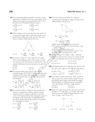
![(a)
ε0
1
1
2
2
3
3
A
d
K
d
K
d
K
+ +
(b)
ε0
1 2 3
1 2 3
A
d d d
K K K
+ +
+ +
(c)
ε0 1 2 3
1 2 3
A K K K
d d d
( )
(d) ε0
1
1
2
2
3
3
AK
d
AK
d
AK
d
+ +
163 The equivalent capacitance between A and B will be
(a) 2 C (b)
C
2
(c) 3C (d)
2
C
164 Four plates of equal area A are separated by equal
distances d and are arranged as shown in the figure.
The equivalent capacity is
(a)
2 0
ε A
d
(b)
3 0
ε A
d
(c)
4 0
ε A
d
(d)
ε0A
d
165 Four plates of the same area of cross-section are
joined as shown in the figure. The distance between
each plate is d. The equivalent capacity across A and
B will be
(a)
2 0
ε A
d
(b)
3 0
ε A
d
(c)
3
2
0
ε A
d
(d)
ε0A
d
166 Three equal capacitors, each with capacitance C are
connected as shown in figure. Then, the equivalent
capacitance between point A and B is
(a) C (b) 3C (c)
C
3
(d)
3
2
C
167 If a slab of insulating material 4 10 3
× −
m thick is
introduced between the plates of a parallel plate
capacitor, the separation between plates has to be
increased by 3 5 10 3
. × −
m to restore the capacity to
original value. The dielectric constant of the material
will be
(a) 6 (b) 8 (c) 10 (d) 12
168 In this figure, the equivalent capacitance between A
and B will be
(a)
C
2
(b)
C
3
(c) 3C (d) 2C
169 The resultant capacitance of given circuit between
points P and Q is
(a) 3C (b) 2C (c) C (d)
C
3
170 In the figure, a capacitor is filled with dielectrics.
The resultant capacitance is
(a)
2 1 1 1
0
1 2 3
ε A
d K K K
+ +
(b)
ε0
1 2 3
1 1 1
A
d K K K
+ +
(c)
2 0
1 2 3
ε A
d
K K K
[ ]
+ +
(d) None of the above
171 The equivalent capacitance between points A and B
in the circuit will be
(a) 10/3 µF (b) 4 µF
(c) 6 µF (d) 8 µF
130 OBJECTIVE Physics Vol. 2
A C 2C 4C 8C B
∞
A B
A
B
A B
C C C
C
C
2C 2C
2C 2C
2C 2C
D
E
B
A
C
P
Q
2C
2C
2C
C C
C
d
K1
K2
A/2 A/2
d/2
K3
4 F
µ
4 F
µ
4 F
µ
4 F
µ
4 F
µ
A
B](https://image.slidesharecdn.com/arihantneetobjectivephysicsvolume2bydcpandey2022edition-230417145135-9bce7664/85/Arihant_NEET_Objective_Physics_Volume_2_By_DC_Pandey_2022_Edition-pdf-141-320.jpg)
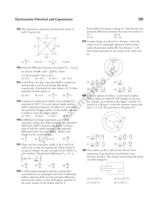
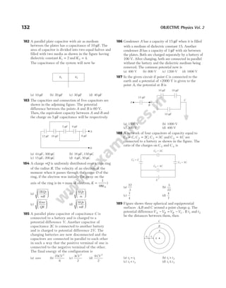
![190 A charged oil drop of mass 2.5× −
10 7
kg is in space
between the two plates, each of area 2 10 2
× −
m2
of a
parallel plate capacitor. When the upper plate has a
charge of 5 10 7
× −
C and the lower plate has an equal
negative charge, then the oil remains stationary. The
charge of the oil drop is ( /
take, g = 10 2
m s )
(a) 9 10 1
× −
C (b) 9 10 6
× −
C
(c) 8.85 10 C
13
× −
(d) 1.8 10 C
14
× −
191 A parallel plate capacitor is made of two dielectric
blocks in series. One of the blocks has thickness d1
and dielectric constant K1 and the other has
thickness d2 and dielectric constant K2 as shown in
figure. This arrangement can be thought as a
dielectric slab of thickness d d d
( )
= +
1 2 and
effective dielectric constant K. The K is
[NCERT Exemplar]
(a)
K d K d
d d
1 1 2 2
1 2
+
+
(b)
K d K d
K K
1 1 2 2
1 2
+
+
(c)
K K d d
K d K d
1 2 1 2
1 2 2 1
( )
+
+
(d)
2 1 2
1 2
K K
K K
+
192 A number of condensers, each of the capacitance
1µF and each one of which gets punctured if a
potential difference just exceeding 500 V is applied,
are provided. An arrangement suitable for giving
capacitance of 2 µF across which 3000 V may be
applied requires at least
(a) 6 component capacitors (b) 12 component capacitors
(c) 72 component capacitors(d) 2 component capacitors
193 A series combination of n1 capacitors, each of value
C1, is charged by a source of potential difference 4V.
When another parallel combination of n2 capacitors,
each of value C 2, is charged by a source of potential
differenceV, it has the same (total) energy stored in
it, as the first combination has. The value of C 2, in
terms of C1 is, then
(a)
2 1
1 2
C
n n
(b) 16 1
2
1
n
n
C (c) 2 2
1
1
n
n
C (d)
16 1
1 2
C
n n
194 Two charges + 6 µC and − 4 µC are placed 15 cm
apart as shown. At what distances from A to its
right, the electrostatic potential is zero (distances
in cm)?
(a) 4, 9, 60 (b) 9, 45, infinity
(c) 20, 45, infinity (d) 9, 15, 45
195 Assume that an electric field E i
= 30 2
x $ exists in
space. Then, the potential differenceV V
A o
− , where
Vo is the potential at the origin andVA is the
potential at x = 2 m, is
(a) 120 V (b) − 120 V (c) − 80 V (d) 80 V
196 An electron initially at rest falls a distance of 1.5 cm
in a uniform electric field of magnitude 2 104
× N/C.
The time taken by the electron to fall this distance is
(a) 1.3 s
× 102
(b) 2.1 s
× −
10 2
(c) 1.6 s
× −
10 10
(d) 2.9 s
× −
10 9
197 The potential at a point x (measured in µm) due to
some charges situated on the X-axis is given by
V x
x
( )
( )
=
−
20
4
2
V. The electric field E at x = 4 µm is
given by
(a) 5/3 V/µm and in the negative x-direction
(b) 5/3 V/µm and in the positive x-direction
(c) 10/9 V/µm and in the negative x-direction
(d) 10/9 V/µm and in the positive x-direction
198 Three charges Q, +q and +q are placed at the
vertices of a right angled isosceles triangle as shown.
The net electrostatic energy of the configuration is
zero, if Q is equal to
(a)
−
+
q
1 2
(b)
−
+
2
2 2
q
(c) − 2q (d) + q
199 Four point charges each +q is placed on the
circumference of a circle of diameter 2d in such a
way that they form a square. The potential at the
centre (in CGS unit) is
(a) zero (b)
4q
d
(c)
4d
q
(d)
q
d
4
200 The resultant capacitance between A and B in the
following figure is equal to
(a) 1 µF (b) 3 µF (c) 2 µF (d) 1.5 µF
Electrostatic Potential and Capacitance 133
d2
d1 K1
K2
A B
+ 6 × 10 C
–6
− 4 × 10 C
–6
15 cm
a
+q +q
Q
B
A
3 F
µ
3 F
µ
3 F
µ
3 F
µ
3 F
µ
3 F
µ
2 F
µ
2 F
µ 3 F
µ](https://image.slidesharecdn.com/arihantneetobjectivephysicsvolume2bydcpandey2022edition-230417145135-9bce7664/85/Arihant_NEET_Objective_Physics_Volume_2_By_DC_Pandey_2022_Edition-pdf-144-320.jpg)
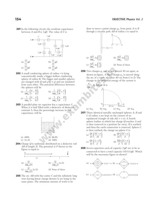
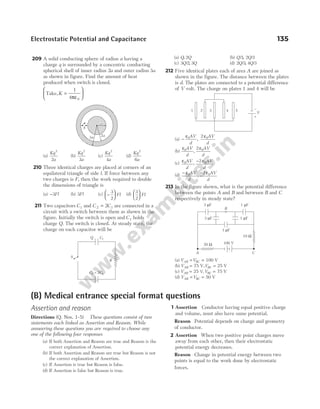
![3 Assertion A charged capacitor is disconnected
from a battery. Now, if its plates are separated
further, the potential energy will fall.
Reason Energy stored in a capacitor is equal to the
work done in charging it.
4 Assertion When a capacitor is charged by a
battery, half of the energy supplied by the battery is
stored in the capacitor and rest half is lost.
Reason If resistance in the circuit is zero, then
there will be no loss of energy.
5 Assertion If the distance between parallel plates of
a capacitor is halved and dielectric constant is made
three times, then the capacitance becomes 6 times.
Reason Capacity of the capacitor depends upon the
nature of the material between the plates.
Statement based questions
1 An electric dipole of moment p is placed in a
uniform electric field E. Then,
(i) the torque on the dipole is p E
× .
(ii) the potential energy of the system is p E
⋅ .
(iii) the resultant force on the dipole is zero.
Choose the correct option, based on above
statements.
(a) (i), (ii) and (iii) are correct
(b) (i) and (iii) are correct and (ii) is wrong
(c) Only (i) is correct
(d) (i) and (ii) are correct and (iii) is wrong
2 Identify the false statement.
(a) Inside a charged or neutral conductor electrostatic field
is zero.
(b) The electrostatic field at the surface of the charged
conductor must be tangential to the surface at any point.
(c) There is no net charge at any point inside the
conductor.
(d) Electrostatic potential is constant throughout the
volume of the conductor.
3 The electrostatic potential on the surface of a
charged conducting sphere is 100V. Two statements
are made in this regard.
S1 : At any point inside the sphere, electric
intensity is zero.
S2 : At any point inside the sphere, the electrostatic
potential is 100 V.
Which of the following is a correct statement?
(a) S1 is true but S2 is false. [NCERT Exemplar]
(b) Both S1 and S2 are false.
(c) S1 is true, S2 is also true and S1 is the cause of S2.
(d) S1 is true, S2 is also true but the statements are
independent.
4 A long, hollow conducting cylinder is kept coaxially
inside another long, hollow conducting cylinder of
larger radius. Both the cylinders are initially
electrically neutral, then choose the correct
statement.
(a) A potential difference appears between the two cylinders
when a charge density is given to the inner cylinder.
(b) A potential difference appears between the two
cylinders when a charge density is given to the outer
cylinder.
(c) No potential difference appears betwen the two
cylinders when a uniform line charge is kept along the
axis of the cylinders.
(d) No potential difference appears between the two
cylinders when same charge density is given to both
the cylinders.
5 The curve represents the distribution of potential
along the straight line joining the two charges Q1 and
Q2 (separated by a distance r), then which is of the
following statements are correct?
1. | | | |
Q Q
1 2
>
2. Q1 is positive in nature.
3. A and B are equilibrium points.
4. C is a point of unstable equilibrium.
(a) 1 and 2 (b) 1, 2 and 3
(c) 1, 2 and 4 (d) 1, 2, 3 and 4
Match the columns
1 Two charges +q and −q are placed at distance r.
Match the following two columns when distance
between them is changed to r ′ and choose the
correct code.
Column I Column II
A. r r
′ = 2 (p) Potential energy will become half
B. r
r
′ =
2
(q) Force between them will become
1
4
th
C. r r
′ = 4 (r) Potential energy will become four times
D. r
r
′ =
4
(s) None
136 OBJECTIVE Physics Vol. 2
y
Q1 A Q2 C
B
x
r](https://image.slidesharecdn.com/arihantneetobjectivephysicsvolume2bydcpandey2022edition-230417145135-9bce7664/85/Arihant_NEET_Objective_Physics_Volume_2_By_DC_Pandey_2022_Edition-pdf-147-320.jpg)
![Electrostatic Potential and Capacitance 137
Codes
A B C D
(a) p,q s s r
(b) p s r s
(c) p,q q s s
(d) r,r p q r
2 A capacitor is connected with a battery. With
battery remains connected some changes are done in
capacitor/battery, which are given in Column I.
Corresponding to it match the two columns and
choose the correct code.
Column I Column II
A. Distance between capacitor
plates is halved
(p) Capacity of capacitor will
become two times
B. A metallic slab completely
filled between the plates
(q) Charge stored in capacitor
will become two times
C. A dielectric slab of
dielectric constant K = 2 is
completely filled between
the plates
(r) Energy stored in capacitor
will become two times
(s) Capacitance become infinite
Codes
A B C A B C
(a) p,q,s s q (b) q,r s p,q
(c) p,q,r s p,q,r (d) r,p,q q s,q,r
3 A parallel plate capacitor is charged by a battery
which is then disconnected. A dielectric slab is then
inserted to fill the space between the plates. Match
the changes that could occur with Column II and
choose the correct code.
Column I Column II
A. Charge on the capacitor
plates
(p) Decrease by a factor of K
B. Intensity of electric field (q) Increase by a factor of K
C. Energy stored (r) Remains same
D. Capacitance (s) None
Codes
A B C D A B C D
(a) p s q r (b) r p p q
(c) r q s p (d) p r q s
4 The area of parallel plates of an air-filled capacitor is
0.20 m2
and the distance between them is 0.01 m.
The potential difference across the plates is 3000 V.
When a 0.01 m thick dielectric sheet is introduced
between the plates, then the potential difference
decreases to 1000 V. Now, match the two columns
(all in SI units) and choose the correct code.
Column I Column II
A. Capacitance of air-filled capacitor (p) 5.31× −
10 7
B. Charge on each plate (q) 5.31× −
10 10
C. Dielectric constant of the material (r) 3
D. Capacitance after the dielectric
sheet is introduced
(s) 1.77 × −
10 10
Codes
A B C D A B C D
(a) q s p r (b) s r p q
(c) s p r q (d) q r p s
(C) Medical entrances’ gallery
Collection of questions asked in NEET and various medical entrance exams
1 In a certain region of space with volume 0.2 m3
, the
electric potential is found to be 5 V throughout. The
magnitude of electric field in this region is
[NEET 2020]
(a) 0.5 N/C (b) 1 N/C (c) 5 N/C (d) zero
2 The capacitance of a parallel plate capacitor with air
as medium is 6µF. With the introduction of a
dielectric medium, the capacitance becomes 30 µF.
The permittivity of the medium is
(take, ε = × −
0
12
10
8.85 C N m
2 1 2
− −
) [NEET 2020]
(a)177 10 12
. × −
C N m
2 1 2
− −
(b) 0 44 10 10
. × −
C N m
2 1 2
− −
(c) 5 00
. C N m
2 1 2
− −
(d) 0 44 10 13
. × −
C N m
2 1 2
− −
3 A short electric dipole has a dipole moment of
16 10 9
× −
C-m. The electric potential due to the
dipole at a point at a distance of 0.6 m from the
centre of the dipole, situated on a line making an
angle of 60° with the dipole axis is
1
4
9 10
0
9 2
πε
= ×
Nm C
/ 2
[NEET 2020]
(a) 200 V (b) 400 V
(c) zero (d) 50 V
4 The variation of electrostatic potential with radial
distance r from the centre of a positively charged
metallic thin shell of radius R is given by the graph
[NEET 2020]](https://image.slidesharecdn.com/arihantneetobjectivephysicsvolume2bydcpandey2022edition-230417145135-9bce7664/85/Arihant_NEET_Objective_Physics_Volume_2_By_DC_Pandey_2022_Edition-pdf-148-320.jpg)
![5. A parallel plate capacitor having cross-sectional area
A and separation d has air in between the plates.
Now, an insulating slab of same area but thickness
d /2 is inserted between the plates as shown in
figure having dielectric constant K( )
= 4 . The ratio of
new capacitance to its original capacitance will be
[NEET 2020]
(a) 2 : 1 (b) 8 : 5 (c) 6 : 5 (d) 4 : 1
6 A capacitor of capacitance15nF having dielectric
slab of ε =
r 25
. , dielectric strength 30 MV/m and
potential difference = 30 V. Calculate the area of the
plate. [AIIMS 2019]
(a) 6 7 10 4
. × −
m2
(b) 4 2 10 4
. × −
m2
(c) 8 0 10 4
. × −
m2
(d) 9 85 10 4
. × −
m2
7 Potential difference is given as
V x x y
( ) = − 2
volt. Find electric field at
a point (1, 2). [JIPMER 2019]
(a) $ $
i j
+ 4 Vm−1
(b) − −
4$ $
i j Vm−1
(c) 4$ $
i j
+ Vm−1
(d) 4$ $
i j
− Vm−1
8 In a parallel plate capacitor, the capacity increases, if
(a) area of the plate is decreased [MHT CET 2019]
(b) distance between the plates increases
(c) area of the plate is increased
(d) dielectric constant decrease
9 A parallel plate capacitor is charged. If the plates are
pulled apart [DCE 2019]
(a) the capacitance increases
(b) the potential difference increases
(c) the total charge increases
(d) the charge and potential difference remains the same
10 The electrostatic force between the metal plates of
an isolated parallel plate capacitor C having a charge
Q and area A is [NEET 2018]
(a) proportional to square root of the distance between the
plates
(b) linearly proportional to the distance between the plates
(c) independent of the distance between the plates
(d) inversely proportional to the distance between the
plates
11 An infinite number of identical capacitor each of
capacitance1µF are connected as shown in the
figure. Then, the equivalent capacitance between A
and B is [AIIMS 2018]
(a)1µF (b)
1
2
µF
(c) 2 µF (d) ∞
12 Find the capacitance as shown in the figure.
[JIPMER 2018]
(a) 2 1
0
KA K d
ε / ( )
+ (b)
2 0
KA
d
ε
(c) (K A d
+ 1 2
0
) /
ε (d)
2
1
0
2
KA
K d
ε
( )
+
13 If a capacitor having capacitance 2F and plate
separation of 0.5 cm, will have area [JIPMER 2018]
(a)1130 cm2
(b) 1130 km2
(c)1130 m2
(d) None of these
14 Charges + q and − q are placed at points A and B
respectively, which are a distance 2L apart, C is the
mid-point between A and B. The work done in
moving a charge + Q along the semi-circle CRD is
[AIIMS 2017]
(a)
qQ
L
4 0
πε
(b)
qQ
L
2 0
πε
(c)
qQ
L
6 0
πε
(d)
− qQ
L
6 0
πε
138 OBJECTIVE Physics Vol. 2
8 capacitors
16 capacitors
∞
A B
d
d/2
K
d/2
d
K
R
A C B D
R
V
r
(a)
R
V
r
(b)
R
V
r
(c)
R
r
(d)
V](https://image.slidesharecdn.com/arihantneetobjectivephysicsvolume2bydcpandey2022edition-230417145135-9bce7664/85/Arihant_NEET_Objective_Physics_Volume_2_By_DC_Pandey_2022_Edition-pdf-149-320.jpg)
![15 Two capacitors C and C /2 are connected to a battery
of V volts, as shown below [AIIMS 2017]
The work done in charging both the capacitor fully
is
(a) 2 2
CV (b) ( / )
1 2 2
CV (c) ( / )
3 4 2
CV (d) ( / )
1 4 2
CV
16 A charged particle q is shot with speed v towards
another fixed charged particle Q. It approaches Q
upto a closest distance r and then returns. If q were
given a speed 2v, the closest distance of approach
would be [JIPMER 2017]
(a) r (b) 2r (c) r / 2 (d) r / 4
17 A parallel plate capacitor of capacitance 100 pF is to
be constructed by using paper sheets of 1 mm
thickness as dielectric. If the dielectric constant of
paper is 4, the number of circular metal foils of
diameter 2 cm each required for the purpose is
[VITEEE 2017]
(a) 40 (b) 20 (c) 30 (d) 10
18 A capacitor of 2µF is charged as shown in the figure.
When the switch S is turned to position 2, the
percentage of its stored energy dissipated is [NEET 2016]
(a) 20% (b) 75% (c) 80% (d) 0%
19 A parallel plate capacitor of area A, plate separation
d and capacitance C is filled with four dielectric
materials having dielectric constants K K K
1 2 3
, , and
K4 as shown in the figure below. If a single
dielectric material is to be used to have the same
capacitance C in this capacitor, then its dielectric
constant K is given by [NEET 2016]
(a) K K K K K
= + + +
1 2 3 4
3
(b) K K K K K
= + + +
2
3
2
1 2 3 4
( )
(c)
2 3 1
1 2 3 4
K K K K K
=
+ +
+
(d)
1 1 1 1 3
2
1 2 3 4
K K K K K
= + + +
20 A parallel plate air capacitor of capacitance C is
connected to a cell of emfV and then disconnected
from it. A dielectric slab of dielectric constant K,
which can just fill the air gap of the capacitor, is
now inserted in it. Which of the following is
incorrect? [CBSE AIPMT 2015]
(a) The potential difference between the plates decreases
K times
(b) The energy stored in the capacitor decreases K times
(c) The change in energy stored is
1
2
1
1
2
CV
K
−
(d) The charge on the capacitor is not conserved
21 An electron of mass Me , initially at rest, moves
through a certain distance in a uniform electric field
in time t1 . A proton of mass Mp also initially at rest,
takes time t2 to move through an equal distance in
this uniform electric field. Neglecting the effect of
gravity, the ratio t t
2 1
/ is nearly equal to [AIIMS 2015]
(a) 1 (b)
M
M
p
e
(c)
M
M
e
p
(d)
M
M
e
p
22 An isolated sphere has a capacitance of 50 pF. What
would be the radius of the sphere? [UK PMT 2015]
(a) 90 cm (b) 45 cm
(c) 11.50 cm (d) 5.75 cm
23 A parallel plate capacitor has 91 plates, all are
identical and arranged with same spacing between
them. If the capacitance between adjacent plates is
3 pF. What will be the resultant capacitance?
[EAMCET 2015]
(a) 273 pF (b) 30 pF
(c) 94 pF (d) 270 pF
24 A particle of mass1.96 × −
10 15
kg is kept in
equilibrium between two horizontal metal plates
having potential difference of 400 V separated apart
by 0.02 m. Then, the charge on the particle is
(e = electronic charge) [Kerala CEE 2015]
(a) 3e (b) 6e
(c) 2e (d) 5e
(e) 4e
Electrostatic Potential and Capacitance 139
d
d/2
A
A/3 A/3 A/3
K1 K2 K3
K4
V 2 F
µ
8 F
µ
1 2
S
V C C/2
v
Q
q r](https://image.slidesharecdn.com/arihantneetobjectivephysicsvolume2bydcpandey2022edition-230417145135-9bce7664/85/Arihant_NEET_Objective_Physics_Volume_2_By_DC_Pandey_2022_Edition-pdf-150-320.jpg)
![25 The distance of the closest approach of an alpha
particle fired at a nucleus with kinetic energy K is
r0 . The distance of the closest approach when the α
particle is fired at the same nucleus with kinetic
energy 2K will be [Guj. CET 2015]
(a) 4 0
r (b)
r0
2
(c)
r0
4
(d) 2 0
r
26 A uniform electric field is created between two
parallel charged plates as shown below. An electron
enters the field symmetrically between the plates
with a speed of v 0 . The length of each plate is l.
Find the angle of deviation of path of the electron as
it comes out of the field. [CG PMT 2015]
(a) θ = −
tan 1
0
2
El
mv
(b) θ =
−
tan 1
0
2
eEl
mv
(c) θ =
−
tan 1
0
eEl
mv
(d) θ =
−
tan 1
0
2
eE
mv
27 A battery charges a parallel plate capacitor separated
by distance ( )
d so that the energy ( )
V0 is stored in the
system. A slab of dielectric constant ( )
K and
thickness ( )
d is then introduced between the plates
of capacitor. The new energy of the system is given
by [CG PMT 2015]
(a) KV0 (b) K V
2
0
(c)
V
K
0
(d)
V
K
0
2
28 A capacitor of capacitance 100 µF is charged by
connecting it to a battery of voltage 12 V with
internal resistance 2 Ω. The time after which 99% of
the maximum charge is stored on the capacitor is
[UP CPMT 2015]
(a) 0.92 ms (b) 0.72 ms (c) 0.34 ms (d) 0.54 ms
29 A parallel plate capacitor is charged and then
isolated. The effect of increasing the plate separation
on charge, potential and capacitance respectively are
[KCET 2015]
(a) constant, decreases, increases
(b) constant, decreases, decreases
(c) constant, increases, decreases
(d) increases, decreases, decreases
30 A spherical shell of radius 10 cm is carrying a charge
q. If the electric potential at distances 5 cm, 10 cm
and 15 cm from the centre of the spherical shell is
V V V
1 2 3
, and respectively, then [KCET 2015]
(a)V V V
1 2 3
= > (b)V V V
1 2 3
> >
(c)V V V
1 2 3
= < (d)V V V
1 2 3
< <
31 Calculate the charge on equivalent capacitance of the
combination shown in figure between the points P
and N. [UK PMT 2015]
(a) 450 µC (b) 225 µC (c) 350 µC (d) 900 µC
32 Consider the diagram,
A parallel plate capacitor has the plate width t and
length L while the separation between the plates
is d. The capacitor is connected to a battery of
voltage ratingV. A dielectric which carefully
occupy, the space between the plates of the
capacitor is slowly inserted between the plates.
When length x of the dielectric slab is introduced
into the capacitor, then energy stored in the system
is [UP CPMT 2015]
(a)
ε0
2
2
tV
d
L (b)
ε0
2
2
1
tV
d
L x
[ ]
+
(c)
ε0
2
2
1
tV
d
L x K
[ ( )]
+ − (d)
ε0
2 2 2
2
2
2
1
t V
d
L x
[ ]
+ +
33 A conducting sphere of radius R is given a charge Q.
The electric potential and the electric field at the
centre of the sphere respectively are
[CBSE AIPMT 2014]
(a) zero and
Q
R
4 0
2
πε
(b)
Q
R
4 0
πε
and zero
(c)
Q
R
4 0
πε
and
Q
R
4 0
2
πε
(d) Both are zero
34 Two thin dielectric slabs of dielectric constants K1
and K K K
2 1 2
, ( )
< are inserted between the plates of
a parallel plate capacitor, as shown in the figure
alongside. The variation of electric field E between
the plates with distance d as measured from plate P
is correctly shown by [CBSE AIPMT 2014]
140 OBJECTIVE Physics Vol. 2
+ + + + + + + +
– – – – – – – – – –
l
E
θ
L
x
(Battery)
V
Dielectric
30 V
P
N
30 F
µ
10 F
µ 20 F
µ
+
+
+
+
+
+
+
P
–
–
–
–
–
–
–
Q
K1 K2](https://image.slidesharecdn.com/arihantneetobjectivephysicsvolume2bydcpandey2022edition-230417145135-9bce7664/85/Arihant_NEET_Objective_Physics_Volume_2_By_DC_Pandey_2022_Edition-pdf-151-320.jpg)
![35 Two charges of equal magnitude q are placed in air
at a distance 2a apart and third charge − 2q is placed
at mid-point. The potential energy of the system is
(where, ε0 = permittivity of free space)
[MHT CET 2014]
(a) −
q
a
2
0
8πε
(b) −
3
8
2
0
q
a
πε
(c) −
5
8
2
0
q
a
πε
(d) −
7
8
2
0
q
a
πε
36 Consider two concentric spherical metal shells of
radii r1 and r r r
2 2 1
( )
> . If the outer shell has a charge
q and the inner one is grounded, then the charge on
the inner shell is [WB JEE 2014]
(a)
− r
r
q
2
1
(b) zero (c)
− r
r
q
1
2
(d) − q
37 What is the electric potential at a distance of 9 cm
from 3 nC? [KCET 2014]
(a) 270 V (b) 3 V
(c) 300 V (d) 30 V
38 Three capacitors 3 µ µ
F F
, 6 and 6 µF are connected
in series to a source of 120 V. The potential
difference in volt, across the 3 µF capacitor will be
[WB JEE 2014]
(a) 24 V (b) 30 V
(c) 40 V (d) 60 V
39 The capacitance of two concentric spherical shells of
radii R1 and R R R
2 2 1
( )
> is [EAMCET 2014]
(a) 4 0 2
πε R (b) 4 0
2 1
1 2
πε
( )
R R
R R
−
(c) 4 0
1 2
2 1
πε
R R
R R
( )
−
(d) 4 0 1
πε R
40 Two capacitors of 10 pF and 20 pF are connected to
200 V and 100 V sources, respectively. If they are
connected by the wire, then what is the common
potential of the capacitors? [KCET 2014]
(a) 133.3 V (b) 150 V
(c) 300 V (d) 400 V
41 In the given figure, the capacitors C C C
1 3 4
, , and C 5
have a capacitance 4 µF each. If the capacitor C 2 has
a capacitance10 µF, then effective capacitance
between A and B will be [UK PMT 2014]
(a) 2 µF (b) 4 µF (c) 6 µF (d) 8 µF
42 Two concentric spheres kept in air have radii R and
r. They have similar charge and equal surface charge
density σ. The electrical potential at their common
centre is (where, ε0 = permittivity of free space)
[MHT CET 2014]
(a)
σ
ε
( )
R r
+
0
(b)
σ
ε
( )
R r
−
0
(c)
σ
ε
( )
R r
+
2 0
(d)
σ
ε
( )
R r
+
4 0
43 A B
, and C are three points in a uniform electric
field. The electric potential is [NEET 2013]
(a) maximum at A
(b) maximum at B
(c) maximum at C
(d) same at all the three points A B
, and C
44 A hollow sphere of radius 0.1 m has a charge of
5 10 8
× −
C. The potential at a distance of 5 cm from
the centre of the sphere is
1
4
9 10
0
9
πε
= ×
−
Nm C
2 2
[J&K CET 2013]
(a) 4000 V (b) 4500 V
(c) 5000 V (d) 6000 V
45 Two identical capacitors are first connected in series
and then in parallel. The ratio of equivalent
capacitance is [J&K CET 2013]
(a) 1 1
: (b) 1 2
:
(c) 1 3
: (d) 1 4
:
46 Two capacitors having capacitances C1 and C 2 are
charged with 120 V and 200 V batteries,
respectively. When they are connected in parallel
now, it is found that the potential on each one of
them is zero. Then, [EAMCET 2013]
(a) 5 3
C C
1 2
= (b) 8 5
1 2
C C
=
(c) 9 5
1 2
C C
= (d) 3 5
1 2
C C
=
Electrostatic Potential and Capacitance 141
B
A
C1
C4
C2 C3
C5
B
A
C
E
(a)
d
O
E
(b)
d
E
(c)
d
E
(d)
d
E
O
O O](https://image.slidesharecdn.com/arihantneetobjectivephysicsvolume2bydcpandey2022edition-230417145135-9bce7664/85/Arihant_NEET_Objective_Physics_Volume_2_By_DC_Pandey_2022_Edition-pdf-152-320.jpg)
![47 A small oil drop of mass 10 6
−
kg is hanging in at rest
between two plates separated by 1 mm having a
potential difference of 500 V. The charge on the
drop is (g = −
10 ms )
2
[Karnataka CET 2013]
(a) 2 10 9
× −
C (b) 2 10 11
× −
C
(c) 2 10 6
× −
C (d) 2 10 9
× −
C
48 Two metal spheres of radii 0.01 m and 0.02 m are
given a charge of 15 mC and 45 mC, respectively.
They are then connected by a wire. The final charge
on the first sphere is … × −
10 3
C. [Karnataka CET 2013]
(a) 40 (b) 30
(c) 20 (d) 10
49 The concentric spheres of radii R and r have positive
charges q1 and q 2 with equal surface charge densities.
What is the electric potential at their common centre?
[Karnataka CET 2013]
(a)
σ
ε0
( )
R r
+ (b)
σ
ε0
( )
R r
−
(c)
σ
ε0
1 1
R r
+
(d)
σ
ε0
1
R
50 See the diagram, area of each plate is 2.0 m2
and
d = × −
2 10 3
m. A charge of 8.85 10 C
8
× −
is given
to Q. Then, the potential of Q becomes
[Karnataka CET 2013]
(a) 13 V (b) 10 V
(c) 6.67 V (d) 8.825 V
51 A soap bubble is charged to a potential 12 V. If its
radius is doubled, then the potential of the bubble
becomes [Kerala CET 2013]
(a) 12 V (b) 24 V
(c) 3 V (d) 6 V
(e) 9 V
52 A sphere of 4 cm radius is suspended within a
hollow sphere of 6 cm radius. If the inner sphere is
charged to a potential 3 esu while the outer sphere is
earthed, then the charge on the inner sphere will be
[UP CPMT 2013]
(a)
1
4
esu (b) 30 esu
(c) 36 esu (d) 54 esu
53 In the adjoining figure, the potential difference
across the 4.5 F
µ capacitor is [UP CPMT 2013]
(a) 4 V (b) 6 V
(c) 8 V (d) 4.5 V
54 Four point charges − −
Q q q
, , 2 and 2Q are placed,
one at each corner of the square. The relation
between Q and q for which the potential at the
centre of the square is zero, is [CBSE AIPMT 2012]
(a) Q q
= − (b) Q
q
= −
1
(c) Q q
= (d) Q
q
=
1
55 A spherical drop of capacitance 1 µF is broken into
eight drops of equal radius. Then, the capacitance of
each small drop is [AIIMS 2012]
(a)
1
2
µF (b)
1
4
µF (c)
1
8
µF (d) 8 µF
56 The equivalent capacitance between points A and B
will be [BCECE (Mains) 2012]
(a) 10 µF (b) 15 µF (c) 10.8 µF (d) 69 µF
57 Four metallic plates each with a surface area of one
side A are placed at a distance d from each other as
shown in figure. Then, the capacitance of the system
between X and Y is [BCECE (Mains) 2012]
(a)
2 0
ε A
d
(b)
2
3
0
ε A
d
(c)
3 0
ε A
d
(d)
3
2
0
ε A
d
58 Four capacitors each of capacity 8 µF are connected
with each other as shown in figure. The equivalent
capacitance between points X andY will be [BHU 2012]
142 OBJECTIVE Physics Vol. 2
3 F
µ
4.5 F
µ
6 F
µ
12V
9 F
µ 24 F
µ
12 F
µ
18 F
µ
6 F
µ
A B
P
Q
R
d
2d
Y
X](https://image.slidesharecdn.com/arihantneetobjectivephysicsvolume2bydcpandey2022edition-230417145135-9bce7664/85/Arihant_NEET_Objective_Physics_Volume_2_By_DC_Pandey_2022_Edition-pdf-153-320.jpg)
![Electrostatic Potential and Capacitance 143
(a) 2 µF (b) 8 µF (c) 16 µF (d) 32 µF
59 The equivalent capacity between points A and B in
figure will be, while capacitance of each capacitor is
3 µF. [UP CPMT 2012]
(a) 2 µF (b) 4 µF (c) 7µF (d) 9 µF
60 In the arrangement of capacitors shown in figure,
each capacitor is of 9 µF, then the equivalent
capacitance between the points A and B is
[UP CPMT 2012]
(a) 9 µF (b) 18 µF (c) 4 5
. µF (d)15 µF
61 A capacitor having capacity of 2 µF is charged to
200 V and then the plates of the capacitor are
connected to a resistance wire. The heat produced
(in joule) will be [Manipal 2012]
(a) 2 10 2
× −
(b) 4 10 2
× −
(c) 4 104
× (d) 4 1010
×
62 The potential of a large liquid drop when eight liquid
drops are combined is 20 V. Then, the potential of
each single drop was [Manipal 2012]
(a) 10 V (b) 7.5 V (c) 5 V (d) 2.5 V
63 The electric field in a certain region is given by
E i j
= −
5 3
$ $ kV/m. The potential differenceV V
B A
−
between points A and B, having coordinates
(4, 0, 3) m and (10, 3, 0) m respectively, is equal to
[AMU 2012]
(a) 21 kV (b) − 21 kV
(c) 39 kV (d) − 39 kV
64 In a parallel plate capacitor with plate area A and
charge Q, the force on one plate because of the
charge on the other is equal to [AMU 2012]
(a)
Q
A
2
0
2
ε
(b)
Q
A
2
0
2
2ε
(c)
Q
A
2
0
ε
(d)
Q
A
2
0
2 ε
65 Two capacitors 3 µF and 4 µF, are individually
charged across a 6 V battery. After being
disconnected from the battery, they are connected
together with the negative plate of one attached to
the positive plate of the other. What is the final total
energy stored? [AMU 2012]
(a)1.26 10 J
4
× −
(b) 2.57 10 J
4
× −
(c)1.26 10 J
6
× −
(d) 2.57 10 J
6
× −
66 The equivalent capacitance between A and B for the
combination of capacitors shown in figure, where all
capacitances are in microfarad is [AFMC 2012]
(a) 6.0 µF (b) 4.0 µF
(c) 2.0 µF (d) 3.0 µF
67 It is possible to have a positively charged body at
[AIIMS 2011]
(a) zero potential (b) negative potential
(c) positive potential (d) All of these
68 If an electron is brought towards another electron,
then the electric potential energy of the system
[AIIMS 2011]
(a) increases (b) decreases
(c) become zero (d) remaining the same
69 Electric potential of earth is taken to be zero because
earth is a good [AIIMS 2011]
(a) insulator (b) conductor
(c) semiconductor (d) dielectric
70 When a capacitor is connected to a battery,
[AIIMS 2011]
(a) a current flows in the circuit for sometime, then
decreases to zero
(b) no current flows in the circuit at all
(c) an alternating current flows in the circuit
(d) None of the above
71 Which of the following is not true? [EAMCET 2011]
(a) For a point charge, the electrostatic potential varies
as1/r
(b) For a dipole, the potential depends on the position
vector and dipole moment vector
(c) The electric dipole potential varies as1 / r at large
distance
(d) For a point charge, the electrostatic field varies
as1 2
/r
4.0 F
µ
6.0 F
µ
3 F
µ
1.0 F
µ
8.0 F
µ
2.0 F
µ
A
B
A
× B
d
×
d
d
A
B
C1
C2 C3
C4
X
Y](https://image.slidesharecdn.com/arihantneetobjectivephysicsvolume2bydcpandey2022edition-230417145135-9bce7664/85/Arihant_NEET_Objective_Physics_Volume_2_By_DC_Pandey_2022_Edition-pdf-154-320.jpg)
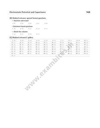
![Now,
∂
∂
=
∂
∂
=
V
x
x
V
y
8 0
, and
∂
∂
=
V
z
0
Hence, E i
= − 8x$ V/m. So, at point (1m, 0, 2m)
E i
= − 8$ V/m or 8, along negative X-axis.
15 (a) We have, electric field,
E
dV
dx
d
dx
x x x
= − = − + − = − −
( )
5 10 9 10 10
2
∴ ( )
E x= = − × − = −
1 10 1 10 20 V/m
l CHECK POINT 2.2
1 (c) Work done in displacing a charge particle is given by
W qV V
AB B A
= −
( ) and the line integral of electrical field from
point A to B gives potential differenceV V E dl
B A
A
B
− = − ⋅
∫
For equipotential surface,V V
B A
− = 0 and henceW = 0.
3 (b) Potential,V
Kq
r
KZe
r
= = =
× × × ×
×
−
−
9 10 50 16 10
9 10
9 19
15
.
= ×
8 106
V
4 (b) Since, potential inside the hollow sphere is same as that on
the surface.
5 (a) Let Q1 and Q2 are the charges on sphere of radii R1 and R2,
respectively.
Surface charge density, σ =
charge
area
According to given problem, σ σ
1 2
=
Q
R
Q
R
1
1
2
2
2
2
4 4
π π
=
∴
Q
Q
R
R
1
2
1
2
2
2
= …(i)
In case of a charged sphere,
V
Q
R
s =
1
4 0
πε
∴ V
Q
R
V
Q
R
1
0
1
1
2
0
2
2
1
4
1
4
= =
πε πε
,
⇒
V
V
Q
R
R
Q
Q
Q
R
R
1
2
1
1
2
2
1
2
2
1
= × = ×
=
×
=
R
R
R
R
R
R
1
2
2
2
1
1
2
[using Eq. (i)]
6 (c) Let ′
q be the charge on the inner shell. Then, the potential
of the inner is
V = potential due to its own ′
q + potential due to the outer charge
= +
1
4 1 2
πε
q
r
q
r
ButV = 0, because the inner shell is earthed.
∴
q
r
q
r
1
1
2
2
+ = 0 ′
q = −
q
r
r
1
2
7 (b) Potential inside the sphere will be same as that on its
surface, i.e.V V
q
= =
surface
10
stat volt,V
q
out =
15
stat volt
∴
V
V
out
=
2
3
⇒ V V
out =
2
3
8 (c) Inside a conducting body, potential is same everywhere
and equals to the potential at its surface.
9 (d) If charge acquired by the smaller sphere is q, then its
potential, 120
2
=
kq
. …(i)
Whole charge comes to outer sphere.
Also, potential of the outer sphere,
V
kq
=
6
…(ii)
From Eq. (i) and (ii), we get
V = 40 V
10 (a) V a b c
A = − +
σ
ε0
( )
V
a
c
b c
B = − +
σ
ε0
2
⇒ V
a
c
b
c
c
C = − +
σ
ε0
2 2
On putting c a b
= + ⇒V V V
A C B
= ≠
12 (c) Potential, V
q
r
= ⋅
1
4 0
πε
= × ×
× −
9 10
500 10
10
9
6
.
= ×
45 106
. V
13 (a) The kinetic energy gained by a charge of q coulomb
through a potential difference ofV volt is
K qV
= J
K = × −
( ) ( )
1.6 10 2000
19
= × −
3.2 J
10 16
We have, K mv
=
1
2
2
v
K
m
= =
× ×
×
= ×
−
−
2 2 10
9 10
8
3
10
16
31
7
3.2
m/s
14 (a) Speed of the particle,v
QV
m
=
2
⇒ v Q
∝ ⇒
v
v
Q
Q
q
q
A
B
A
B
= = =
16
4
2
1
Electrostatic Potential and Capacitance 147
σ
–σ
σ
c
b
a
A
B
C
R1
Q1
R2
Q2](https://image.slidesharecdn.com/arihantneetobjectivephysicsvolume2bydcpandey2022edition-230417145135-9bce7664/85/Arihant_NEET_Objective_Physics_Volume_2_By_DC_Pandey_2022_Edition-pdf-158-320.jpg)
![15 (c) The kinetic energy of the electron,
K eV mv
= =
1
2
2
⇒ V
mv
e
=
1
2
2
Here, v
c
= =
×
= ×
10
3 10
10
3 10
8
7
m/s
V =
× ×
×
− −
−
1
2
10 10
10
31 7 2
19
( ) ( )
( )
9.0 3.0
1.6
Potential, V = 2531V
l CHECK POINT 2.3
1 (b) ∆ PE = Work done by external agent
= − > ⇒ >
( ),
V q Vq V V
f i f i ∆PE 0, i.e. PE will increase.
2 (b) Potential energy of the system will be given by
=
− −
=
( )( )
e e
r
e
r
4 4
0
2
0
πε πε
As, r decreases, potential energy increases.
3 (c) Work done,W U U QQ
r r
f i
= − = × × −
9 10
1 1
9
1 2
2 1
⇒ W = × × × × ×
− −
9 10 12 10 8 10
9 6 6 1
4 10
1
10 10
2 2
×
−
×
− −
= ≈
12.96 J 13 J
4 (a) Since, the proton is moving against the direction of electric
field, so work is done by the proton against electric field. It
implies that electric field does negative work on the proton.
Again, proton is moving in electric field from low potential
region to high potential region, hence its potential energy
increases.
5 (c) Electric potential energy,U
q q
d
=
1
4 0
1 2
πε
∴ U =
× × × × − ×
− −
−
(9 10 ) (1.6 10 ) ( 1.6 10 ) J
10
9 19 19
10
= − × × × = −
−
9 109
1.6 10 eV 14.4 eV
9
Note In the solution given all the values are positive. It is
important to mention the sign.
6 (c) Potential energy as well as force are positive, if there is
repulsion between the particles and negative, if there is
attraction.
We take only the magnitude of values when discussing
decrease or increase of energy.
As, U
QQ
r
= 1 2
0
4πε
Plus or minus i.e., whether both are of the same sign or
different, if r decreases, the value increase. Therefore,
option (c) is wrong.
7 (b) Potential energy of charges Q1 and Q2 at 10 cm apart,
Ui =
× × ×
− −
1
4
12 10 5 10
01
0
6 6
πε .
=
× × ×
= × =
−
−
9 10 60 10
01
54 10 54
9 12
1
.
. J
Potential energy of charge Q1 and Q2 at 6 cm apart,
U2
9 12
9 10 60 10
0 06
9
=
× × ×
=
−
.
J
∴ Work done = −
( . )
9 54 J = 36
. J
8 (d) We have, AB AC
+ = 12 cm …(i)
AB AC
⋅ = 32 cm2
∴ AB AC AB AC AB AC
− = + − ⋅
( )2
4
AB AC
− = 4 cm
From Eqs. (i) and (ii), we get
AB = 8 cm, AC = 4 cm
Potential energy at point A,
U
q q
AB
q q
AC
A
A B A C
= +
1
4 0
πε
=
× × ×
+
=
−
−
9 10 4 10
10
1
8
1
4
9 12
2
1.35 J
9 (c) Potential energy,U
QQ
r
Q Q
r
QQ
r
= + +
1
4 0
1 2
1
2 3
2
1 3
3
πε
Net potential energy,U
q
l
net = ⋅
3
4 0
2
πε
10 (a) Potential energy of the system,
U K
Qq
l
Kq
l
KqQ
l
= + + =
2
0
⇒
Kq
l
Q q Q Q
q
( )
+ + = ⇒ = −
0
2
11 (d) Length of the diagonal of a cube having each side b is
3 b. So, distance of centre of cube from each vertex is
3
2
b
.
Hence, potential energy of the given system of charge is
U
q q
b
q
b
= × ⋅
−
=
−
8
1
4 3 2
4
3
0
2
0
πε πε
( )( )
/
12 (a) Change in potential energy (∆U U U
f i
) = −
⇒ Potential energy,
∆U
q q q q q q q q
= +
− +
1
4 0 4 01 0 4 0 5
0
1 3 2 3 1 3 2 3
πε . . . .
⇒ ∆U q q
q
q
= =
1
4
8
4
8
0
2 3
3
0
2
πε πε
[ ] ( )
∴ k q
= 8 2
148 OBJECTIVE Physics Vol. 2
D
q3
40 cm
50 cm
q2
q1
30 cm 10 cm
40 cm
C
A B](https://image.slidesharecdn.com/arihantneetobjectivephysicsvolume2bydcpandey2022edition-230417145135-9bce7664/85/Arihant_NEET_Objective_Physics_Volume_2_By_DC_Pandey_2022_Edition-pdf-159-320.jpg)
![13 (c) Torque, τmax = pE = q l E
( )
2 = × × × ×
−
2 10 0 01 5 10
6 5
.
= × −
10 10 3
N-m
14 (d) Work done, W pE
= −
( cos )
1 θ = − °
pE ( cos )
1 180
W pE
= − −
[ ( )]
1 1 = 2pE
15 (a) Given, q1 1
= C, q2 2
= C, q3 3
= C and r1 100
= cm = 1m
Initial PE of system,U
r
1
0 1
1
4
=
πε
(q q q q q q
1 2 2 3 3 1
+ + )
=
×
9 10
1
9
(1 2 2 3 3 1
× + × + × )
= ×
99 109
J
When r2 = 50 cm = 0.5 m
Final PE of system,U2 =
1
4 2
πε0r
(q q q q q q
1 2 2 3 3 1
+ + )
=
×
9 10
0 5
9
.
(1 2 2 3 3 1
× + × + × ) = × ×
2 99 109
J
Work done,W U U
= −
2 1 = 2 99 10 99 10
9 9
× × − ×
= ×
99 109
J = 9.9 ×10¹⁰
J
l CHECK POINT 2.4
1 (d) H O N
2 2 2
, , etc., are not polar dielectrics.
2 (c) Volume of 8 small drops = Volume of big drop
8
4
3
4
3
3 3
× =
π π
r R ⇒R r
= 2
As, capacity is proportional to r, hence capacity
become 2 times.
3 (c) Capacity of a spherical conductor is C R
= 4 0
πε .
4 (c) For spherical conductor,
C R
= 4 0
πε
Q V R
=
4
3
3
π and A R
= 4 2
π
∴ R
V
A
=
3
∴ Capacitance, C
V
A
= 12 0
πε
5 (d) Given, 2 2
πR = ⇒R =
1
π
For sphere C KR
= 4 0
πε
⇒ C =
×
× ×
1
9 10
1
80
9
π
(for water K = 80)
Capacitance of sphere, C = 282828
. pF ≈ 2800 pF
6 (d) We have, C
A
d
=
ε0
⇒ C
d
∝
1
Therefore, the capacity of parallel plate condenser depends on
the separation between the plates.
7 (c) Since, aluminium is a metal and very thin, therefore field
inside this will be zero. Hence, it would not affect the field in
between the two plates, so capacity = =
q
V
q
Ed
, remains
unchanged.
8 (a) The potential difference across the parallel plate capacitor,
V = − − =
10 10 20
( ) volt
∴Capacitance = = =
Q
V
40
20
2F
9 (d) C
A
d
=
ε0
. As A→
1
2
times and d → 2 times
So, C →
1
4
times, i.e. C C
′ = = =
1
4
12
4
3µF
10 (d) Capacitance, C KC
medium air
=
⇒ K
C
C
= = =
medium
air
2.20
110
50
11 (d) Charge on capacitor, when its potential becomes 10 V,
Q CV
= = × × = ×
− −
500 10 10 5000 10
6 6
µC
∴ Required time =
×
×
=
−
−
5000 10
100 10
50
6
6
s
12 (b) C
A
d
= =
ε0
1pF and C
K A
d
= =
ε0
2
2 pF
∴ K = 4.
13 (b)
Capacitance in air, C
A
d
air = =
ε0
9
Capacitance in medium,
1 1 1
1 2
1
1 0 2 0
C C C
d
K A
d
K A
med
= + = +
ε ε
⇒ C
K K A
Kd K d
med =
+
1 2 0
1 2 2 1
ε
=
× ×
× + ×
= × =
3 6
3 2 3 6 3
18
4
9 40 5
0
ε A
d d
/ /
. pF
14 (a) Parallel plate capacitor, C K A d
= ε0 /
As, given in figure, for series combination,
1 1
2
1
2
0 0
C A
d
A
d
′
= +
ε 2ε
⇒C
A
d
=
4
3
0
ε
l CHECK POINT 2.5
1 (c) Capacitor are in series,
1 1 1 1 3
C C C C C
′
= + + =
∴Capacitance, C
C
′ =
3
Total voltage of the series combination,
V V V V V V V V
′ = + + = + + =
1 2 3 3
2 (c) In series,
1 1
2
1
2
1
2
C
= + +
⇒ Capacitance, C =
2
3
F
Electrostatic Potential and Capacitance 149
d
air
A
2 /3
d
K2 = 6
A
K
1
=
3
d/3](https://image.slidesharecdn.com/arihantneetobjectivephysicsvolume2bydcpandey2022edition-230417145135-9bce7664/85/Arihant_NEET_Objective_Physics_Volume_2_By_DC_Pandey_2022_Edition-pdf-160-320.jpg)
![20 (a) Inside a sphere, potential remains constant.
21 (b) Radius of spherical conductor, R = 5 cm = × −
5 10 2
m
According to given situation,V
q
R
= ⋅
1
4 0
πε
V
q
= ⋅
× −
1
4 5 10
0
2
πε
⇒
q
4
5 10
0
2
πε
= × −
V …(i)
Again, electric potential at distance r = 30 cm = × −
30 10 2
m
from the centre,
V
q
′ = ⋅
× −
1
4 30 10
0
2
πε
=
×
× −
q
4
1
30 10
0
2
πε
=
×
×
−
−
5 10
30 10
2
2
V
=
V
6
[from Eq. (i)]
22 ( )
a Electric field is given by
E
V
r
= − =
− −
× −
∆
∆
30 10
2 10 2
( )
= 2000 V/m
23 (d) Potential at a point due to electric dipole
V
p
r
=
cos θ
2
If θ = °
0 , thenV will be maximum
and if θ = °
180 , thenV will be minimum.
24 (c)U pE
= − cos θ, U is minimum at θ = °
0 .
25 ( )
a Kinetic energy gained by α-particle,
KE = ⋅ = −
q V qV V
∆ ( )
1 2 = −
2 1 2
eV V
( )
= × × −
−
2 10 70 50
19
1.6 ( ) = 40 eV
26 (c) KE = = =
1
2
1
2
1
2
2 2
2
2
mv m at m
qE
m
t
( ) Q a
qE
m
=
=
E q t
m
2 2 2
2
27 (a) Work done,W U U
f i
= − =
ε
−
q q
r r
f i
1 2
0
4
1 1
π
= × −
−
( ) ( ) ( ) ( )
9 10 10 12 8
1
0 06
1
01
9 12
. .
= 5.8 J
28 (c) Capacitance, C R
= 4 0
πε
=
×
× ×
1
9 10
6408 10
9
3
= 712µF
29 (d) If metallic slab fills the complete space between the plates
or both plates are joined through a matellic wire, then
capacitance became infinite.
30 (c) Energy stored, W
Q
C
=
2
2
∴ W Q
∝ 2
(if C is constant)
or
W
W
Q
Q
Q
Q
′
= =
2
2
2
2
2 4
( )
∴ W W
′ = 4
31 (c) Heat produced in capacitor = Energy of charged capacitor
=
1
2
2
CV = × × ×
−
1
2
2 10 100
6 2
( ) ( ) = 0 01
. J
32 (b) The energy stored,U nC V
=
1
2
2
( )
33 (d) Change in energy of condenser,
∆U U U
= −
2 1 = −
1
2
1
2
2
2
1
2
CV CV
= −
V
C C
2
2 1
2
( ) = × − ×
− −
( )
( )
100
2
10 10 2 10
2
6 6
= × −
4 10 2
J
34 (b) In series, charge remains same on both capacitors
∴ U
Q
C
=
2
2
or U
C
∝
1
(QQ Q
1 2
= )
∴
U
U
C
C
1
2
2
1
0 6
0 3
= =
.
.
∴ U U
1 2 2 1
: :
=
35 (b) In parallel combination, C C C
net = +
1 2
V
q
C
CV
C C
= =
+
net
net
1 0
1 2
36 (c) Let Q C V
0 0 0
, , andU0 be the charge, capacitance, potential
difference and stored energy, respectively before the
dielectric slab of dielectric constant K is inserted.
After inserting dielectric slab, charge will remain same, i.e.
Q Q
′ = 0.
Potential difference will decrease asV
V
K
′ = 0
Stored energy will decrease as,U
V
K
= 0
.
37 (b) Potential on parallel plate capacitor,V
Q
C
= .
Also, capacity of parallel plate capacitor is given by
C
KA
d
=
ε0
∴ V
Qd
KA
=
ε0
152 OBJECTIVE Physics Vol. 2
70V 50V
V1 V2
α
0.3 F
µ 0.6 F
µ
6 V](https://image.slidesharecdn.com/arihantneetobjectivephysicsvolume2bydcpandey2022edition-230417145135-9bce7664/85/Arihant_NEET_Objective_Physics_Volume_2_By_DC_Pandey_2022_Edition-pdf-163-320.jpg)
![or acceleration of the particle,
a
qE
m
= =
× ×
×
−
−
3 10 80
20 10
3
3
= 12 m/s2
So, from equations of motion,
v u at
= + = + ×
20 12 3 = 56 m/s
72 ( )
a
Potential,V V V V V
q
r
A B C D
= = = = =
ε
⋅
1
4 0
π
V = ⋅
× −
1
4
50 10
2
0
6
πε
( )
( )
∴ Potential at the centre of square,
V V
0 4
=
V0
9 6
4
9 10 50 10
2
= ×
× × ×
−
= ×
90 2 104
V
Work done in bringing a charge ( )
q = 50 µC from ∞ to centre
of the square is
∴ W qV
= 0 = × × ×
−
50 10 90 2 10
6 4
= 63 64
. J ~
− 64 J
73 (c) U
q q
a
AB = ⋅
−
1
4
2
0
πε
( )( )
U
q q
a
BC = ⋅
−
1
4
2
0
πε
( )( )
U
q q
a
CA = ⋅
1
4 2
0
πε
( )( )
Potantial energy of the system,
∴ U
q
a
q
a
q
a
system = ⋅
−
− +
1
4
2 2
2
0
2 2 2
πε
U
q
a
system =
−7
8
2
0
πε
74 ( )
b When α-particle is accelerated through a potential
difference V, then kinetic energy of α-particle,
K qV
= = ( )
2eV = × × ×
−
2 16 10 10
19 6
. J
=
× × ×
×
−
−
2 1.6 10 10
1.6 10
19 6
19
eV = 2 MeV
75 ( )
d Since, we know that, K
p
m
=
2
2
Also, K qV
=
∴ p mqV
= 2
∴Ratio of momenta,
p
p
m q
m q
m
m
e e e e
α α α α
= =
2
(Qq qe
α = 2 )
76 (d) Velocity,v at
qE
m
t
= =
⇒ v
q
m
∝ or KE ∝
q
m
2
2
∴ The ratio of kinetic energy,
K
K
1
2
2
2
1 2
16
=
=
/
: 1
77 (c) Capacity of spherical condenser, when outer sphere is
earthed,
C
ab
b a
1 0
4
= ⋅
−
πε
Capacity of spherical condenser when inner sphere is earthed
C b
ab
b a
2 0
0
4
4
= +
−
πε
πε
∴ Difference in their capacity = −
C C
2 1 = 4 0
πε b
78 (d) Work done, W U U
f i
= −
Here, Uf = 0
∴ W Ui
= − = −
1
4 0
πε
q q
r
q q
r
q q
r
1 2 2 3 3 1
+ +
= −
×
− + + − × −
( )
[( ) ( ) ( ) ( ) ( ) ( )]
9 10
1 2 1 4 2 4 10
9
12
0.1
= 0.54 J
79 (d) Here,
1
2 4
1 1
2 1 2
0
mv
q q
r r
i f
=
πε
–
1
2
2 10 10 9 10 0 9
3 2 9 9
× × × = ×
– –
( ) ( ) ( . )
v
Speed of particle, v = ×
8.1 10 m/s
3
= 90 m/s
80 (b) Work done,W U U
q q
r
i f
= − = ⋅
⋅
−
6
1
4
0
0
πε
=
6
4
2
0
q
r
πε
81 ( )
d Given circuit is balanced Wheatstone bridge circuit.
For branch ACB, C′ =
×
+
=
10 10
10 10
5µF
Electrostatic Potential and Capacitance 155
b
Air
a
O
A B
C
D
10 F
µ 10 F
µ
10 F
µ 10 F
µ
q q
− 2 q
A C
B
2a
a
A B
D C
50 C
µ
50 C
µ
50 C
µ
50 C
µ
√2
1
O](https://image.slidesharecdn.com/arihantneetobjectivephysicsvolume2bydcpandey2022edition-230417145135-9bce7664/85/Arihant_NEET_Objective_Physics_Volume_2_By_DC_Pandey_2022_Edition-pdf-166-320.jpg)
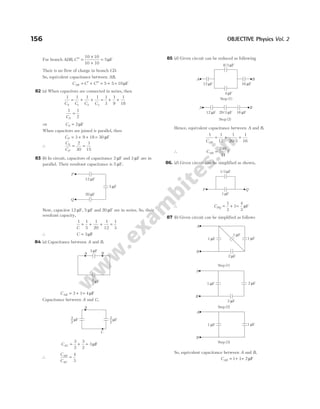
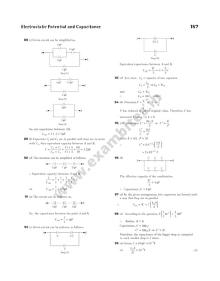
![Now, both capacitors are in parallel.
∴ C C C
A
d
K A
D
′ = + = +
1 2
0 0
2 2
ε ε
( / ) ( / )
⇒ C
A
d
A
d
′ = +
= = × −
ε ε
0 0 5
1
2
2
5
2
5
2
10 [from Eq. (i)]
= 25µF
100 (d) Capacity of capacitor, C
A
d
=
ε0
⇒ C
d
∝
1
∴Capacitance, C C
′ = 2
∴Extra charge flow, q CV CV
= −
( )
2 = CV
∴ Work done, W qV
= = ( )
CV V = CV2
101 (b)
C
C
A d t
A d
d
d t
′
=
−
=
−
ε
ε
0
0
/ ( )
/
⇒ = =
d
d
( / )
5 7
7
5
∴ Capacitance, C′ = × =
7
5
25 F 35 F
µ µ
102 (b) On introducing dielectric K in a parallel plate capacitor, its
capacity becomes,
C KC
′ = 0
∴ C C
′ = 5 0
Also, energy stored,W
q
C
0
2
0
2
=
∴ W
q
C
q
C
′ =
′
=
×
2 2
0
2 2 5
∴
W
W
0 5
1
′
=
∴ W
W
′ = 0
5
103 (b)
C
C
A d t
A d
d
d t
d
d
′
=
−
=
−
= =
ε
ε
0
0 2
2 1
/
/ /
:
Qin question, thickness is
( )
t b
d
=
2
104 (d) When charged capacitor is filled with a dielectric material
of dielectric constant K, then charge remains constant, V
becomes
1
K
times and E becomes
1
K
times.
So, new value of charge is Q0.
New value ofV
V V
=
×
=
0 0
3
9 3
New value of E
E E
=
×
=
0 0
3
9 3
105 (d) Here capacitors of capacity 4 µF each are in parallel, their
equivalent capacity is 8 µF. Now, there is a combination of
three capacitors in series of capacity 20 µF, 8 µF and 12 µF
so, their resultant capacity,
1 1
20
1
8
1
12
C
= + +
∴ C =
120
31
µF
Total charge, Q CV
= = ×
120
31
300 = 1161µC
∴ Charge through 4 µF capacitor =
1161
2
= 580 µC
and potential difference across 4 µF condenser,
V
q
C
= = =
580
4
145V
106 (c) As capacitors C C
1 2
and are in series, then there should be
equal charge on them, i.e.
charge on charge on
C C
1 2
=
∴ C V V C V V
A D D B
1 2
( ) ( )
− = −
or C V V C V V
D D
1 1 2 2
( ) ( )
− = −
or CV CV CV CV
D D
1 1 1 2 2 2
− = −
or V C C CV CV
D ( )
1 2 1 1 2 2
+ = +
∴ The potential difference of point D,
V
CV CV
C C
D =
+
+
1 1 2 2
1 2
107 (a) Equivalent capacitance of circuit,
Ceq =
+ +
=
6
3 2 1
1µF
Total charge, Q = ×
1 24 = 24µC
Now, potential difference across 6 µF capacitor = =
24
6
4 V
108 (c) Given, circuit can be reduced as,
Let potential at P beVP and potential at B beVB.
As capacitors 3 µF and 6 µF are in series, they have same
charge.
∴ Charge on Charge on
3 6
µ µ
F F
=
∴ CV CV
1 1 2 2
=
or 31200 6
( ) ( )
− = −
V V V
P P B
As B point is attached to earth.
So, VB = 0
∴ 1200 2
− =
V V
P P
VP = 400 V
158 OBJECTIVE Physics Vol. 2
2 F
µ 3 F
µ 6 F
µ
24 V
+1200
3 F
µ
A 6 F
µ
P B
C2
C1](https://image.slidesharecdn.com/arihantneetobjectivephysicsvolume2bydcpandey2022edition-230417145135-9bce7664/85/Arihant_NEET_Objective_Physics_Volume_2_By_DC_Pandey_2022_Edition-pdf-169-320.jpg)
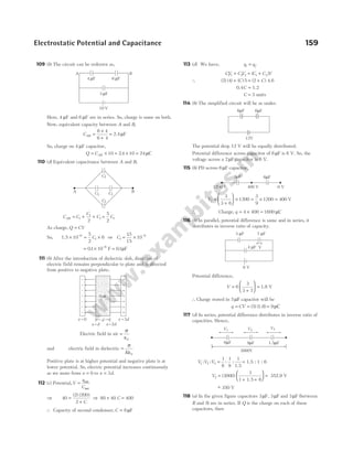
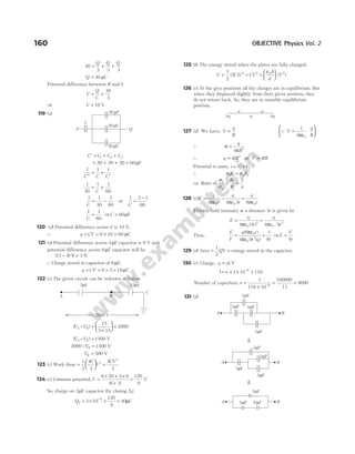
![The effective capacitance between point A and B is 5 µF.
132 (c) Charge, Q CV
= = × × = ×
− −
500 10 10 5 10
6 3
C
Now, Q qt
= or t
Q
q
=
or t =
×
×
−
−
5 10
100 10
3
6
= × =
1
20
1000 50 s
133 (a) By using,
1
2
1
2
2
2
m v v QV
( )
− =
1
2
10 10 600 0
3
1
2 2 8
× − = −
− −
[ ( ) ] ( )
v 0.2
Velocity of the ball at the point A, v1 = 22.8 cms−1
134 (c) In series combination,
1 1
1
1
2
1
4
1
C
= + + =
+ +
=
4 2 1
4
7
4
⇒ C1
4
7
= µF
In parallel combination, C1 1 2 4 7
= + + = µF
∴
C
C
1
2
4 7
7
4
49
= =
/
135 (c) Electric force, qE ma
=
∴ a
qE
m
=
⇒ a =
× × ×
×
−
−
1.6 10 1 10
9 10
19 3
31
=
× −
1.6 10
9
ms
15
2
Initially speed, u = ×
5 106
ms−1
and final speed,v = 0
∴ From v u as
2 2
2
= −
⇒ Distance travelled by electron, s
u
a
=
2
2
s =
× ×
× ×
=
(5 10 ) 9
2 1.6 10
7cm
6 2
15
136 (a) Potential gradient is related with electric field according to
the following relation, E
dV
dr
=
−
.
E i j k
r
= − = − − −
∂
∂
∂
∂
∂
∂
∂
∂
V
r
V
x
V
y
V
z
$ $ $
= + + +
[$ ( ) $ $ ]
i j k
2 3
3 2 2
xy z x xz
137 (c) Potential energy of the system,
−
− + =
kqQ
x
kQq
x
kq
x
2
2
0
⇒
− +
=
4
2
0
2
kqQ kq
x
⇒ kq kQq
2
4
=
Ratio,
q
Q
= 4
138 (c) Electrostatic potential energy,U
q q
r
=
ε
⋅
1
4 0
1 2
π
Here, q q
1 2
19
10
= = × −
1.6 C
and r = × −
9 10 15
m
∴ U =
× × × × ×
×
− −
−
9 10 16 10 16 10
9 10
9 19 19
15
. .
= × −
2 56 10 14
. J
139 (b) When capacitors are connected in parallel, then
C C C C C
P = + + = 3
According to question,
∴ In series, C
C C
C C
s =
×
+
3
3
⇒ 3.75 =
×
3
4
C C
C
⇒ C = 5µF
140 (c) The work done by a electrostatic force is given by
W q V V
12 2 1
= −
( ). Here initial and final potentials are same in all
three cases and same charge is moved, so work done is same
in all three cases.
141 (a) Let Q1 and Q2 be the charge on the two conducting
spheres of radii R1 3
( )
= cm and R2 1
(= cm), respectively.
∴ Potential,V
Q
R
1
1
1
1
4
=
πε0
⇒10
9 10
3 10
9
1
2
=
× ×
× −
Q
⇒ Charge, Q1
2
9
10 3 10
9 10
=
× ×
×
−
…(i)
and V
Q
R
2
0
2
2
1
4
=
πε
⇒ 10
9 10
1 10
9
2
2
=
× ×
× −
Q
⇒ Charge, Q2
2
9
10 1 10
9 10
=
× ×
×
−
…(ii)
According to Coulomb’s law, force of repulsion between
them is
F =
1
4 0
πε
QQ
r
1 2
2
=
× × × × × × ×
× × × × ×
− −
−
9 10 10 3 10 10 1 10
9 10 9 10 10 10
9 2 2
9 9 2 2
( )
[using Eqs. (i) and (ii)]
=
× −
1
3
10 9
N
Electrostatic Potential and Capacitance 161
B
A
3C C
Q1
Q2
10 cm
1cm
3cm
⇓
B
A
3 F
µ
2 F
µ
⇓
A B
5 F
µ](https://image.slidesharecdn.com/arihantneetobjectivephysicsvolume2bydcpandey2022edition-230417145135-9bce7664/85/Arihant_NEET_Objective_Physics_Volume_2_By_DC_Pandey_2022_Edition-pdf-172-320.jpg)
![142 (a) We have, AC BC
=
∴ V V
D E
=
Workdone in taking a charge Q from D to E
W QV V
E D
= −
( )
W = 0
143 (b)
AO = +
( ) ( )
2 2
2 2
AO = =
4 2 and BO = 2
Potential difference between the points A and B
= −
V V
A B
=
ε
−
ε
⋅
1
4
1
4
0 0
π π
Q
AO
Q
BO
= 0 ( )
QAO BO
=
144 (b)
Potential at the centre of the ring 1 is
V1
0
2 2
1
4
10
10
5
10 10
= +
+
πε ( ) ( )
= +
1
4
10
10
5
10 2
0
πε
Potential at the centre of the ring 2 is
V2
0
2 2
1
4
5
10
10
10 10
= +
+
πε ( ) ( )
= +
1
4
5
10
10
10 2
0
πε
Work done,W qV V
= −
( )
1 2
= + − −
q
4
10
10
5
10 2
5
10
10
10 2
0
πε
= −
q
4
5
10
5
10 2
0
πε
= −
q
4
1
2
1
2 2
0
πε
=
−
q
8
2 1
2
0
πε
145 (d) As shown in figure, component of dipole moment along
the line OP will be
p p
′ = cosθ
Hence, electric potential at point P will be
V
p
r
= ⋅
1
4 0
2
πε
θ
cos
146 (b) Total charge is indepedent of r.
Hence, option (b) is incorrect.
147 (c) Length of each side of square is 2 m, so distance of its
centre from each corner is 1m.
Potential at the centre,
V = ×
×
+
×
−
×
+
×
− − − −
9 10
10 10
1
5 10
1
3 10
1
8 10
1
9
6 6 6 6
= ×
1.8 105
V
148 (a) By using,W Q
= ⋅
(E r)
∆
⇒ W Q e e e a b
= + + ⋅ +
[( $ $ $) ( $ $)]
1 2 3
i j k i j
= +
Q e a e b
( )
1 2
149 (c) Point P will lie near the charge which is smaller in
magnitude, i.e. −6µC. Hence, potential at P,
V
x x
=
− ×
+
×
+
=
− −
1
4
6 10 1
4
12 10
0
0
6
0
6
πε πε
( ) ( )
( )
0.2
⇒ x = 0.20 m
150 (d) Work done,W V V
A B
= × −
−
6 10 6
( ) , where
VA =
− ×
×
+
×
×
= ×
− −
10
5 10
15 10
2 10
5 10
1
15
10
10
6
2
6
2
6
( )
V
and VB =
×
×
−
×
×
= − ×
−
− −
10
2 10
15 10
5 10
5 10
13
15
10
10
6
2
6
2
6
( )
V
∴ W = × × − − ×
=
−
6 10
1
15
10
13
15
10 56
6 6 6
. J
151 (d) E
dV
dx
E
dV
dy
x y
= − = − − = = − = −
( ) ,
5 5 3
and E
dV
dz
z = − = − 15
∴ E E E E
x y z
net = + + = + − + − =
2 2 2 2 2 2
5 3 15 7
( ) ( ) ( )
162 OBJECTIVE Physics Vol. 2
E
D
A C
B
q
q
q
A( 2, 2)
√ √
√2
√2 B
(2, 0)
(0, 0)
O
2
10C
10cm 10cm
10cm
O2
O1
5C
p′
θ
O
r
P
p
O
√2m
1m
20 cm
x
P –6 C
µ 12 C
µ](https://image.slidesharecdn.com/arihantneetobjectivephysicsvolume2bydcpandey2022edition-230417145135-9bce7664/85/Arihant_NEET_Objective_Physics_Volume_2_By_DC_Pandey_2022_Edition-pdf-173-320.jpg)
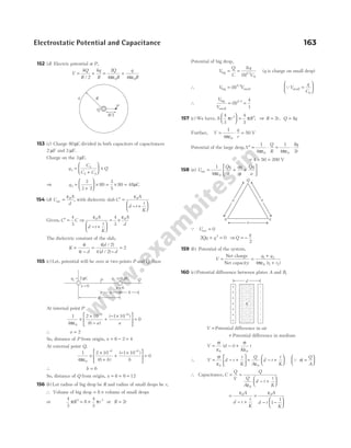
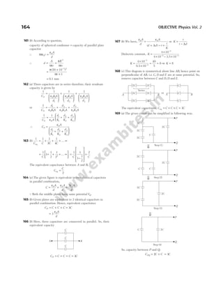

( , )
2 4 0 0
3 4
x y
m m
= −10 V
174 (c)
K Q
a
KQ
a
( )
2
2 2
5
+ =
or
K Q
a
( )
3
2
5
=
∴
KQ
a
=
10
3
Now potential of inner sphere,
V
K Q
a
KQ
a
KQ
a
m = + = =
2
2
5
2
5
2
10
3
=
25
3
V
175 (d) We have,V
KQ
r
= ⇒ 120
2
=
KQ
∴ Kq = 240 units
When it is made to touch the bigger sphere, whole charge will
transfer to bigger sphere.
∴Potential of bigger sphere,V
Kq
= = =
6
240
6
40 V
176 (b) Let radius of drop is r. According to Millikan, for balance
of drop, QE mg
= or Q
V
d
r g
=
4
3
3
π ρ
where, V is potential difference and ρ is density of drop.
∴
Q
Q
r
r
V
V
1
2
1
2
3
2
1
=
×
⇒
Q
Q
r
r
2
3
2
600
2400
2
=
× =
/
⇒ Q Q
2 2
= /
177 (d) Shell C is now earthed.
∴ VC = 0
∴
K q q
a
Kq
a
( )
+ ′
− =
3 4
0
∴ q
q
′ = −
4
Now, potential difference,
V V
Kq
a
Kq
a
Kq
a
A C
− = − − −
2
4
3 4
0
/
=
Kq
a
6
178 (a) Potential difference only depends upon the inner charge.
So, if the shell is given a charge of − 3Q, the new potential
difference between the same two surface isV.
179 (a) The induced charges will be as under.
Electrostatic Potential and Capacitance 165
A
B
4 F
µ
4 F
µ
4 F
µ
4 F
µ
4 F
µ
Series, 2 F
µ Parallel, 6 F
µ
10 C
6 C
6 C
4 C 4 C
A C
C1
C2
a
2a
2Q
Q
QE
O
r
mg
q'
q
–q
A
B
D
C
+q
+q
O
−q 2R
R
r](https://image.slidesharecdn.com/arihantneetobjectivephysicsvolume2bydcpandey2022edition-230417145135-9bce7664/85/Arihant_NEET_Objective_Physics_Volume_2_By_DC_Pandey_2022_Edition-pdf-176-320.jpg)
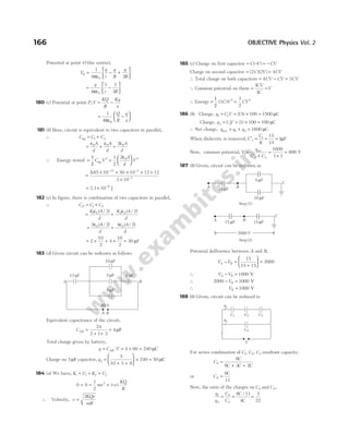
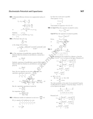
![Hence, variation of potential ( )
V with distance r is given as
5 (b) Capacitance of parallel plate capacitor when medium is air
C
A
d
0
0
=
ε
… (i)
According to second condition,
A A
′ = , t d
= / 2, K = 4
∴Capacitance, C
A
d t
t
K
=
− +
ε0
( )
=
−
+
ε0
2
2
4
A
d
d d /
=
+
ε0
2 8
A
d d
= ⋅
8
5
0
ε A
d
∴
C
C
A
d
A
d
0
0
0
8
5
=
⋅
ε
ε
⇒
C
C0
8
5
=
⇒ C C
: :
0 8 5
=
6 (a) Given, capacitance of a capacitor,
C = 15 nF = × −
15 10 9
F,
εr = 2 5
.
Electric field, E = ×
30 106
V/m
Potential difference,V = 30 V
Area of plate = ?
If d be the distance between the plates, then
d
V
E
= =
×
30
30 106
= −
10 6
m
Capacitance of capacitor,
C
A
d
r
=
ε ε
0
15 10
885 10 2 5
10
9
12
6
× =
× × ×
−
−
−
. . A
⇒ A = × −
67 10 4
. m2
7 (c) Given, potential difference,
V x x y
( ) = − 2
volt
∴ E = − ∆V = − − + −
$ ( ) $ ( )
i j
∂
∂
∂
∂
x
x y
y
x y
2 2
= − − −
[ $ $]
2 2
xy x
i j
= +
2 2
xy x
$ $
i j
E at (1, 2) = × × +
2 1 2 12
$ $
i j = +
4$ $
i j Vm−1
8 (c) In a parallel plate capacitor, the capacity of capacitor,
C
K A
d
=
ε0
∴ C A
∝
So, the capacity of capacitor increases, if area of the plate is
increased.
9 (b) The electric field between the plates is given by
E
V
d
V Ed V d
= = ∝
or or
Hence, if the plates are pulled apart, the potential difference
increases.
10 (c) As we know, the total work in transferring a charge to a
parallel plate capacitor is given as
W
Q
C
=
2
2
… (i)
We can also write a relation for work done as, W F d
= ⋅ … (ii)
From Eqs. (i) and (ii), we get
W
Q
C
Fd
= =
2
2
⇒ F
Q
Cd
=
2
2
…(iii)
As ,the capacitance of a parallel plate capacitor is given as
C
A
d
=
ε0
Substituting the value of C in Eq. (iii), we get
F
Q d
Ad
Q
A
= =
2
0
2
0
2 2
ε ε
Thus, it means electrostatic force is independent of the
distance between the plates.
11 (c) This combination forms a GP,
S = + + + +
1
1
2
1
4
1
8
…
Sum of infinite GP, S
a
r
=
−
1
⇒ S =
−
= =
1
1 1 2
1
1
2
2
/
Hence, capacitance of combination, C∞ = × =
2 1 2
µ µ
F F
12 (a) This combination is same as the two capacitors are
connected in series and distance between plate of each
capacitor is d / 2. So,
C
K A
d
1
0
2
=
ε
/
and C
A
d
2
0
2
=
ε
/
Hence, C
C C
C C
net =
+
1 2
1 2
=
+
2 2
2 2
0 0
0 0
K A
d
A
d
K A
d
A
d
ε ε
ε ε
C
KA
K d
net =
+
2
1
0
ε
( )
172 OBJECTIVE Physics Vol. 2
V
r
V∝
1
r
R](https://image.slidesharecdn.com/arihantneetobjectivephysicsvolume2bydcpandey2022edition-230417145135-9bce7664/85/Arihant_NEET_Objective_Physics_Volume_2_By_DC_Pandey_2022_Edition-pdf-183-320.jpg)
![13 (b)Q Capacitance of a parallel plate capacitor, C
A
d
=
ε0
⇒ A
Cd
=
ε0
=
× ×
×
−
−
2 0 5 10
8854 10
2
12
.
.
⇒ A = 1130 km2
14 (d) In first case, when charge + Q is situated at C.
Electric potential energy of system,
U
q q
L
q Q
L
1
0 0
1
4 2
1
4
= ⋅
−
+ ⋅
−
πε πε
( ) ( )
+
1
4 0
πε
qQ
L
In second case, when charge + Q is moved from C to D.
Electric potential energy of system in this case,
U
q q
L
qQ
L
2
0 0
1
4 2
1
4 3
= ⋅
−
+ ⋅
πε πε
( )
+ ⋅
−
1
4 0
πε
( ) ( )
q Q
L
Work done ( )
∆U U U
= −
2 1
= − ⋅ + ⋅ − ⋅
1
4 2
1
4 3
1
4
0
2
0 0
πε πε πε
q
L
qQ
L
qQ
L
− − ⋅ − ⋅ + ⋅
1
4 2
1
4
1
4
0
2
0 0
πε πε πε
q
L
qQ
L
qQ
L
= −
qQ
L L
4
1
3
1
0
πε
=
−
qQ
L
4
1 3
3
0
πε
( )
= −
2
12 0
qQ
L
πε
= −
qQ
L
6 0
πε
15 (c) The two capacitors are connected in parallel.
The equivalent capacitance,
C C
C C
′ = + =
2
3
2
Work done in charging the equivalent capacitor is stored in
the form of potential energy,
W U C V
= = ′
( / )
1 2 2
W
C
V
= × ×
1
2
3
2
2
W CV
=
3
4
2
16 (d) At closest distance r, the whole kinetic energy of charge q
is converted into potential energy.
∴
1
2
1
4
2
0
mv
Q q
r
=
⋅
πε
⇒ r
Q q
mv
= ⋅
⋅
1
4
2
0
2
πε
In next case, r
Qq
m v
′ =
1
4
2
2
0
2
πε ( )
⇒ r
Qq
mv
′ = ⋅
1
4
1
4
2
0
2
πε
⇒ r
r
′ =
4
17 (d) The arrangement of n metal plates separated by dielectric
acts as parallel combination of ( )
n −1 capacitors.
Therefore, C
n K A
d
=
−
( )
1 0
ε
Here, C = = × −
100 100 10 12
pF F,
K = = × − − −
4 885 10
0
12 2 1 2
, .
ε C N m ,
A r
= = × × −
π 2 2 2
314 1 10
. ( )
and d = = × −
1 1 10 3
mm m
∴100 10
1 4 885 10
314 1 10
1 10
12
12
2 2
× =
− × × ×
× × ×
×
−
−
−
−
( ) ( . )
. ( )
n
3
⇒ n = −
999 10
. ~
18 (c) Consider the given figure,
When the switch S is connected to point 1, then initial energy
stored in the capacitor can be given as
E V
1
6 2
1
2
2 10
= × × ×
−
.
When the switch S is connected to point 2, energy dissipated
on connection across 8µF will be
E
CC
C C
V
2
1 2
1 2
2
1
2
=
+
.
= ×
× × ×
×
− −
−
1
2
2 10 8 10
10
6 6
5
2
V
= × × ×
−
1
2
10 6 2
( )
1.6 V
Therefore, % loss of energy
= × =
× × ×
× × ×
=
−
−
E
E
V
V
2
1
6 2
6 2
100
1
2
16 10
1
2
2 10
80
.
%
19 (c) Given capacitor is equivalent to capacitors K K
1 2
, and K3
in parallel and part of K4 in series with them.
1 1 1
1 2 3 4
C C C C C
eq
=
+ +
+
( )
⇒
1 1
2
3
1
2
0
1 2 3
0
4
0
K A
d
K K K
A
d
K
A
d
ε ε ε
=
+ +
+
[ ] ( )
⇒
2 3 1
1 2 3 4
K K K K K
=
+ +
+
[ ]
20 (d) When a parallel plate air capacitor connected to a cell of
emfV, then charge stored will be
q CV
=
⇒ V
q
C
=
Electrostatic Potential and Capacitance 173
A B
C
L L
+q −q
+Q
A D
B
2L L
+q −q +Q](https://image.slidesharecdn.com/arihantneetobjectivephysicsvolume2bydcpandey2022edition-230417145135-9bce7664/85/Arihant_NEET_Objective_Physics_Volume_2_By_DC_Pandey_2022_Edition-pdf-184-320.jpg)
![⇒
t
200
0 01
µs
= ln ( . )
This gives, t = 920 µs = 0.92 ms
29 (c) After isolation of capacitor, charge is constant.
Capacity, C
A
d
=
ε0
∴Capacitance decreases with increase in distance.
V
Q
C
=
∴ Potential increases with decrease in capacitance (C).
30 (a) Inside the spherical shell potential is same.
∴ V V
1 2
=
Also, V
d
∝
1
, i.e. V V V
1 2 3
= >
31 (a) The equivalent capacitance between the points P and N is
given by
1 1
10 20
1
30
Ceq
=
+
+
( )
= =
2
30
1
15
∴ Ceq = 15µF
Charge on equivalent capacitor having capacitance 15 µF is
Q C V
= eq = × =
15 30 450 µC
32 (c) When length x of the dielectric slab is placed between the
plates of the capacitor, then
C
K t x
d
1
0
=
ε
QC K
A
d
=
ε0
and similarly, C
t L x
d
2
0
=
−
ε ( )
∴ Net capacitance, C C C
t
d
L x K
net = + = + −
1 2
0
1
ε
[ ( )]
Thus, energy stored in the capacitor,
U CV C V
= =
1
2
1
2
2 2
net = + −
ε0
2
2
1
tV
d
L x K
[ ( )]
33 (b) As, we know, Einside = 0
and V V
Q
R
inside surface
= =
1
4 0
πε
34 (c) Graph (c) will be the right graph. The electric field inside
the dielectrics will be less than the electric field outside the
dielectrics. The electric field inside the dielectric could
not be zero.
As, K K
2 1
> , the drop in electric field for dielectric slab K2
must be more than dielectric slab K1.
35 (d) Potential energy of the system,
U
q q
r
q q
r
q q
r
= + +
1
4 0
1 2
12
1 3
13
2 3
23
πε
=
−
+
−
+
1
4
2 2
2
0
πε
q q
a
q q
a
qq
a
( ) ( )
=
−
− +
1
4
2 2
2
0
2 2 2
πε
q
a
q
a
q
a
=
−
+
=
−
1
4
4
2
7
8
0
2 2 2
πε πε0
q
a
q
a
q
a
36 (c) Let the charge on the inner shell be q′.
The total charge will be zero.
So,
Kq
r
Kq
r
′
+ =
1 2
0 ( )
Qr r
2 1
>
∴ ′ =
−
q
Kq r
K r
/
/
2
1
⇒ ′ = −
q
r
r
q
1
2
37 (c) Given, q = = × −
3 3 10 9
nC C
and r = 9 cm = × −
9 10 2
m
We know that, potential due to point charge is given by
V
q
r
=
1
4 0
πε
=
× × ×
×
−
−
9 10 3 10
9 10
9 9
2
= ×
3 102
V
∴ Electric potential,V = 300 V
38 (d) For the combination of three capacitors in series,
1 1 1 1
1 2 3
C C C C
= + + ⇒
1 1
3
1
6
1
6
C
= + + ⇒C = =
6
4
15
. µF
The charge stored in this circuit, q CV
= = ×
15 120
. = 180 µC
The potential difference across the 3µF
q CV
= , V
q
C
= = =
180
3
60 V
39 (c) We know that,
For concentric spherical shells ( )
R R
2 1
> ,
V
Q
R
R1
=
1
4 0 1
πε
. ...(i)
V
Q
R
R2
=
1
4 0 2
πε
. ...(ii)
The common potential of the capacitors,
V V V Q
R R
R R
= − = −
1 2
1
4
1 1
0 1 2
πε
.
Electrostatic Potential and Capacitance 175
R
Einside = 0 Q
q q
–2q
a a
–Q
+Q
R1
R2](https://image.slidesharecdn.com/arihantneetobjectivephysicsvolume2bydcpandey2022edition-230417145135-9bce7664/85/Arihant_NEET_Objective_Physics_Volume_2_By_DC_Pandey_2022_Edition-pdf-186-320.jpg)
![49 (a) Electric potential at their common centre of concentric
spheres is given by
V R r
=
ε
+
σ
0
( )
where, σ is surface charge density.
50 (c) In the given arrangement, plate Q is common for two
capacitors which are connected in parallel.
∴ C C C C
P
eff = = +
1 2
⇒ C
A
d
A
d
A
d
P = + =
ε ε ε
0 0 0
2
3
2
LetV be the potential difference across the capacitor, which is
equal to the potential of the plate Q.
So, the arrangement can be shown as,
Potential, V
Q
C A
d
p
= =
×
ε
−
8.85 10
3
2
8
0
=
× ×
× ×
−
2 10
3 2
8
d 8.85
8.85
=
× × × ×
× × ×
=
− −
−
2 2 10 10
3 10 2
3 8
12
8.85
8.85
6.67 V
51 (d) We know that, potential,V
q
r
=
ε
4π 0
Here, r r
1 = and r r
2 = 2
So, V
q
r
1
0
4
=
ε
π
and V
q
r
2
0
4 2
=
ε
π ( )
Hence,
V
V
q
r
r
q
1
2 0
0
4
4 2
=
ε
×
ε
π
π ( )
⇒
V
V
1
2
2
1
= ;V
V
2
1
2
=
In question,V1 12
= V (given)
So, V2
12
2
6
= = V
52 (c) Let, the charge on the inner sphere be Q, then the charge
induced on the inner surface of the outer sphere is − Q.
∴ Electric potentialV of the inner sphere is given by
V
Q Q
= −
4 6
But V = 3 esu
∴ 3
4 6
= −
Q Q
⇒ Q
1
4
1
6
3
−
= ⇒
Q
12
3
=
∴Charge on the inner sphere, Q = 36 esu
53 (c) The given circuit capacitance between B and D is
C1 3 6 9
= + =
( ) µ µ
F F
Capacitance between A and D,
1 1 1
9
2 1
9
3
9
1
3
2
C
= + =
+
= =
4.5
⇒ C2 3
= µF
Charge on C2 3 12 36
= =
( ) ( )
µ µ
F V C
So, the potential difference between A and B
=
Charge
Capacitance
= =
36
8
µ
µ
C
4.5 F
V
54 (a)
If potential at centre is zero, then
V V V V
1 2 3 4 0
+ + + =
− − + + =
KQ
r
Kq
r
K Q
r
K q
r
2 2
0
− − + + =
Q q q Q
2 2 0
⇒ Q q
= −
55 (a) Let R and r be the radii of bigger and each smaller drop,
respectively.
∴
4
3
8
4
3
3 3
π π
R r
= ×
⇒ R r
= 2 …(i)
The capacitance of a smaller spherical drop is
C r
= 4 0
πε …(ii)
The capacitance of bigger drop is
C R
′ = 4 0
πε = ×
2 4 0
πε r ( )
QR r
= 2
= 2C [from Eq. (ii)]
∴ C
C
=
′
2
=
1
2
µF ( )
QC′ = 1µF
56 (a) The given circuit can be redrawn as,
Electrostatic Potential and Capacitance 177
P
Q, V
R
d
2d
3 F
µ
4.5 F
µ
6 F
µ
12 V
A B D
–q 2q
2Q
–Q
O
12 F
µ
6 F
µ
9 F
µ 18 F
µ
24 F
µ
C2
C1
C3 C4
B
A](https://image.slidesharecdn.com/arihantneetobjectivephysicsvolume2bydcpandey2022edition-230417145135-9bce7664/85/Arihant_NEET_Objective_Physics_Volume_2_By_DC_Pandey_2022_Edition-pdf-188-320.jpg)
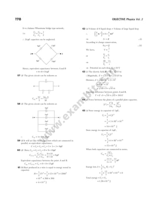
![Electrostatic Potential and Capacitance 179
66 (a) In given figure, C2 and C3 are in parallel.
∴ C C C
′ = + =
2 3 4µF
As C′ and C1 are in series,
1 1 1 1
4
1
4
1 1
C C C
S
=
′
+ = +
⇒ CS1 2
= µF
Similarly, C4 and C5 are in parallel, C′′ = + =
6 2 8µF
C′′ and C6 are in series,
1 1 1 1
8
1
8
2 6
C C C
S
=
′′
+ = +
⇒ CS2 4
= µF
Now, CS1 and CS2 are in parallel, C = + =
4 2 6µF
67 (d) A positively charged body can have positive, negative or
zero potential.
When we ground the charged body, potential difference
between body and ground is zero but not the charge and same
for negatively charged body.
68 (a) The work done against the force of repulsion in moving
the two charges closer, increases the potential energy of the
system.
69 (b) Earth is a conducting sphere of large capacitance.
V q C
= /
As, C is very large, soV → 0 for all finite charges.
Hence, earth is a good conductor.
70 (a) A current flows in the circuit during the time, the
capacitor is charged. After the capacitor gets fully charged,
the current stops flowing. It means when a capacitor is
connected to a battery, a current flows in the circuit for
sometime, then reduces to zero.
71 (c) For a point charge,V
r
∝
1
For a dipole,V
p
r
= ⋅
1
4 0
2
πε
[on axial position]
i.e. V
r
∝
1
2
The electric dipole potential varies as 1/r at large distance is
not true.
C1 = 4.0 F
µ
C4 = 6.0 F
µ
C3 = 3.0 F
µ
C2 = 1.0 F
µ
C6 = 8.0 F
µ
C5 = 2.0 F
µ
A
B](https://image.slidesharecdn.com/arihantneetobjectivephysicsvolume2bydcpandey2022edition-230417145135-9bce7664/85/Arihant_NEET_Objective_Physics_Volume_2_By_DC_Pandey_2022_Edition-pdf-190-320.jpg)
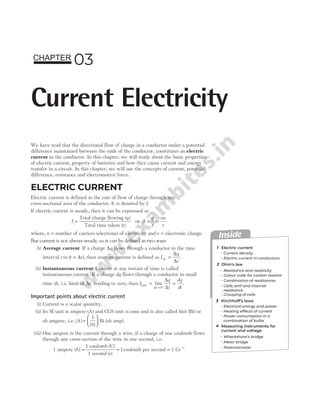
![which means the graph for given current equation is a
straight line with negative slope, i e
. . −2γ and positive
intercept, i e
. .β.
So, the plot will be as shown alongside.
Example 3.6 The current in a wire varies with time
according to the relation,
i A A s t
= +
3 ( ) ( / )
2
(i) How many coulombs of charge pass through a cross-section
of the wire in the time interval between t = 0 to t s
= 4 ?
(ii) What constant current would transport the same charge in
the same time interval?
Sol. Given, i t
= +
3 2
( ) ( )
A A/s
(i) Current through a cross-sectional area is given by
i
dq
dt
=
∴ dq idt
=
On integrating both sides between the given time interval,
i.e. 0 to 4 s, we get
dq idt
q
0 0
4
∫ ∫
=
∴ Charge, q t dt
= +
∫ ( )
3 2
0
4
= +
3
2
2
2
0
4
t
t
= + = +
[ ] [ ]
3 12 16
2
0
4
t t = 28 C
(ii) Therefore, the current flowing through wire would be
i
q
t
= =
28
4
= 7 A
Current density
Current density at any point inside a conductor is defined
as ‘‘the amount of charge flowing per second through a
unit area held normal to the direction of the flow of charge
at that point’’.
Current density is a vector quantity and its direction is
along the motion of the positive charge as shown in
Fig. 3.3 (a).
Current density, J
A A
= =
q t I
/
If the cross-sectional area A is not perpendicular to the
current and normal to the area makes an angle θ with the
direction of the current as shown in Fig. 3.3 (b), then
A A
n = cosθ
∴Current density, J = =
I
A
I
A
n cosθ
or I = ⋅
J A
If area is finite,
I d
= ⋅
∫ J A
where, dA is a small element of the given surface.
The SI unit of current density is ampere per square metre,
i.e. Am 2
−
and its dimensional formula is [AL−2
].
Example 3.7 An electron beam has an aperture of 2 mm 2
. A
total of 7 1016
× electrons flow through any perpendicular
cross-section per second. Calculate the current density in the
electron beam.
Sol. As we know, current density in the electron beam,
J
I
A
ne
t
A
ne
tA
= = =
/
Substituting the values, we get
J =
× × ×
× ×
−
−
7 10 16 10
1 2 10
16 19
6
.
= ×
5 6 103
. Am 2
−
Electric current in conductors
The electric current in a conductor can be explained by
the electron theory. In an atom of a substance, the
electrons in the orbits close to the nucleus are bound to it
under the strong attraction of the nuclear positive charge,
but the electrons far from the nucleus experience a very
feeble force.
Hence, the outer electrons can be removed easily from the
atom (by rubbing or by heating the substance). In fact, a
few outer electrons, leave their atoms and move freely
within the substance (in the vacant spaces between the
atoms). These electrons, called free electrons or
conduction electrons, carry the charge in the substance
from one place to the other.
182 OBJECTIVE Physics Vol. 2
An
Area=A
(a)
I
A
θ
(b)
Area=A
I
A
Fig. 3.3 Direction of current density
β
β γ
/2
O
t
i](https://image.slidesharecdn.com/arihantneetobjectivephysicsvolume2bydcpandey2022edition-230417145135-9bce7664/85/Arihant_NEET_Objective_Physics_Volume_2_By_DC_Pandey_2022_Edition-pdf-193-320.jpg)
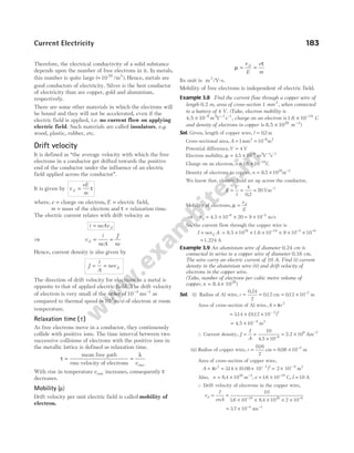
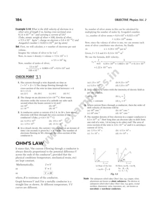
![Resistance and resistivity
The property of a substance by virtue of which it opposes
the flow of current through it, is known as the resistance.
It is defined as ‘the ratio of the potential difference applied
across the ends of the conductor to the current flowing
through’’.
Mathematically, R
V
I
=
The resistance of the conductor depends upon the
following factors
(i) It is directly proportional to the length of the conductor,
i.e. R l
∝ ...(i)
(ii) It is inversely proportional to the area of the
cross-section of the conductor,
i.e. R
A
∝
1
...(ii)
From Eqs. (i) and (ii), we get
R
l
A
∝ ⇒ R
l
A
= ρ ...(iii)
where, ρ is the constant of proportionality known as
resistivity or specific resistance of the conductor.
Resistivity is the intrinsic property of the substance. It is
independent of shape and size of the body and depends
upon the nature of the material.
Example 3.11 Resistance of a conductor of length l and area
of cross-section A is R. If its length is doubled and area of
cross-section is halved, then find its new resistance.
Sol. Initial length = l, area = A
So, initial resistance, R
l
A
= ρ
Final length, l l
′ = 2 , area, A
A
′ =
2
New resistance, R
l
A
l
A
l
A
R
′ =
′
′
=
= =
ρ ρ ρ
2
2
4 4
If its length is doubled and area of cross-section is halved,
then new resistance becomes four times the initial value.
Unit and dimensional formula of resistance
The SI unit of resistance is ohm and is denoted by symbol Ω.
1 ohm ( )
Ω = =
1
1
1
volt (V)
ampere (A)
volt/ampere (or V/A)
The resistance of a conductor is said to be one ohm, if one
ampere of current flows, when a potential difference of
one volt is applied across the ends of the conductor.
Its dimensional formula is [ML T
2 3 2
− −
A ].
Note Any conducting material that offers some resistance is known as
resistor.
Conductance and conductivity
Conductance
Reciprocal of resistance is known as conductance G, i.e.
G
R
=
1
Its unit is1/Ω or Ω −1
or Siemen.
Conductivity
Reciprocal of resistivity is called conductivity (σ), i.e.
σ
ρ
=
1
Its unit is mho/m.
The dimensional formula of conductivity is [ ]
M L T A
− −
1 3 3 2
.
Vector form of Ohm’s law
Electric field in a conductor of length l and having
potential differenceV at its ends is given by
V El
=
Also, V IR El
I l
A
= ⇒ =
ρ
⇒ E
I
A
= ρ
∴ E J
= ρ
or J E
= σ ...(iv)
The above equation is the vector form of Ohm’s law.
Also, current density,
J nev d
= =
ne
eE
m
τ
J
ne
m
E
=
2
τ
Comparing with Eq. (iv), we get
Conductivity, σ
τ
=
ne
m
2
and resistivity, ρ
σ τ
= =
1
2
m
ne
Current Electricity 185
θ
I
V
1
R
tan = =
θ G
Fig. 3.5](https://image.slidesharecdn.com/arihantneetobjectivephysicsvolume2bydcpandey2022edition-230417145135-9bce7664/85/Arihant_NEET_Objective_Physics_Volume_2_By_DC_Pandey_2022_Edition-pdf-196-320.jpg)
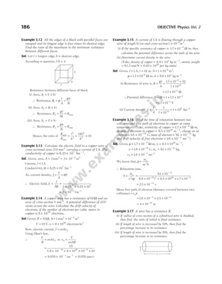
![Sol. (i) According to the question, we draw a figure given below
We have, A l A l
1 1 2 2
=
π π
r l r l l l
2 2
2 2
2 4
= ⇒ =
( ) /
Resistance, R
l
r
1 2
=
ρ
π
, R
l
A
l
r
l
r
2
2
2
2 2
4
4
1
16
= = =
ρ ρ
π
ρ
π
/
Ratio of initial to final resistance,
R
R
1
2
= 16
(ii) Given, l l
1 = , A A
1 = , l l l
2 10
= + % of
= + =
l l l
0.1 1.1 , A A
2 = ′
We have, A l A l
1 1 2 2
= ⇒ Al A l
= ′ ( )
1.1
Area, A
A
′ =
1.1
Resistance, R
l
A
R
l
A
l
A
l
A
= ′ = =
× ×
=
ρ ρ ρ ρ
,
/
( )
2
2
2
1.1
1.1
1.1
R
R
′
= =
(1.1) 1.21
2
Percentage increase in resistance,
R
R
′
−
× =
1 100 ( ) %
1.21 − × =
1 100 21
(iii) Given, l l A A
1 1
= =
,
l l
l
A A
2 2
1
20
100
6
5
= +
= = ′
,
We have, A l A l
1 1 2 2
=
Al A
l
A
A
= ′ ⇒ ′ =
6
5
5
6
∴
R
R
l
A
l
A
l
l
A
A
l
l
A
A
2
1
2
2
1
1
2
1
1
2
6 5
5 6
36
25
= = ⋅ = ⋅ =
ρ
ρ
/
/
Percentage increase in resistance,
R
R
2
1
1 100
36
25
1 100 44
−
× = −
× = %
Temperature dependence of resistivity
Resistivity of a material depends on the temperature.
As, ρ
τ
∝
1
When temperature increases in a conductor, average speed
of free electrons increases, hence relaxation time
decreases. Thus, resistivity increases.
Resistivity of a metal conductor is given by
ρ ρ α
= + −
0 0
1
[ ( )]
T T
where, ρ = resistivity at temperature T, ρ0 = resistivity at
temperatureT0 and α = temperature coefficient of
resistivity.
i.e. α
ρ ρ
ρ
=
−
−
0
0 0
( )
T T
In terms of resistance,
R ∝ ρ
∴ R R T T
= + −
0 0
1
[ ( )]
α
⇒ α =
−
−
R R
R T T
0
0 0
( )
where, R0 = resistance of conductor at 0°C
and Rt = resistance of conductor at t°C.
Important points related to resistivity
For metals, α is positive as their resistivity increases with
rise in temperature. The graph of ρ plotted againstT would
be a straight line as shown in Fig. 3.6 (a).
For semiconductors, α is negative as their resistivity
decreases with rise in temperature. Variation in resistivity
with the temperature for semiconductor is shown in
Fig.3.6 (b).
The resistivity of alloys also increases with rise in
temperature. The graph between resistivity and
temperature is shown in Fig. 3.6 (c).
Example 3.18 The resistance of a thin silver wire is 1.0 Ω at
20°C. The wire is placed in a liquid bath and its resistance
rises to 1.2 Ω. What is the temperature of the bath?
(Take, α for silver = × −
3.8 10 3
per °C)
Sol. We know that, R T R T T
( ) [ ( )]
= + −
0 0
1 α
Here, R T R
( ) ,
= =
1.2 1.0
Ω Ω
0
α = × −
3.8 10 3
per °C
and T0 20
= ° C
Current Electricity 187
2r
l′
P
T
T0
ρ0
ρ
Temperature
(a)
Resistivity
Temperature
(b)
Temperature
(c)
Resistivity
Resistivity
Fig. 3.6 Resistivity as the function of temperature
for (a) metals, (b) semiconductors and (c) alloys](https://image.slidesharecdn.com/arihantneetobjectivephysicsvolume2bydcpandey2022edition-230417145135-9bce7664/85/Arihant_NEET_Objective_Physics_Volume_2_By_DC_Pandey_2022_Edition-pdf-198-320.jpg)
![Substituting the values, we get
1.2 1.0[ 3.8 ( )]
= + × − °
−
1 10 20
3
T
or 3.8 0.2
× − ° =
−
10 20
3
( )
T
Solving this, we get T = °
72.6 C
Example 3.19 Resistance of platinum wire in a platinum
resistance thermometer at melting ice, boiling water and at a
hot bath are 6 Ω, 6.5Ω and 6.2 Ω, respectively. Find the
temperature of hot bath.
Sol. Given, R0 6
= Ω, R100 6
= .5 Ω and Rt = 6.2 Ω
The temperature of platinum resistance thermometer ( )
t is
given by
t
R R
R R
t
=
−
−
× ° =
−
−
× °
0
100 0
100
6
6
C
6.2
6.5
100 C
= × ° = °
0.2
0.5
100 C 40 C
Example 3.20 The temperature coefficient of resistance of a
wire is 0.00145 °C −1
. At 100 °C, its resistance is 2 Ω. At
what temperature, the resistance of the wire will be 3 Ω?
Sol. Using the relation, R R T
= +
0 1
[ ]
α
R R t
1 0 1
1
= +
[ ]
α
∴ 2 1 100
0
= + ×
R [ ]
0.00145 ...(i)
and R R t
2 0 2
1
= +
[ ]
α
∴ 3 1 0 5
0 2
= + ×
R t
[ ]
.0014 ...(ii)
On dividing Eq. (ii) by Eq. (i), we get
3
2 1 100
2
=
+ ×
+ ×
1 0.00145
0.00145
t
or t2 494 8
= ° =
. C 767.8K
Colour code for carbon resistor
In electrical and electronic circuits, there are two major
types of resistors, which are being used, i.e. wire wound
resistors and carbon resistor, offering resistances over a
wide range. Wire wound resistors have resistances upto
few hundred ohm, whereas for higher resistances, resistors
are mostly made up of carbon.
To know the value of resistance of carbon resistors, colour
code is used. These codes are printed in the form of set of
rings or strips. By reading the values of colour bands, we
can estimate the value of resistance.
The carbon resistor has normally four coloured rings or
bands say A B C
, , and D as shown in the Fig. 3.7.
Colour bands A and B indicates the first two significant
figures of resistance in ohm.
Band C indicates the decimal multiplier, i.e. the number
of zeros that follows the two significant figures A and B.
Band D indicates the tolerance in percent as per the
indicated value. In other words, it represents the
percentage accuracy of the indicated value.
The tolerance in the case of gold is ± 5 % and in silver is
±10 %. If only three bands are marked on carbon resistor,
then it indicates a tolerance of 20%. (i.e. no colour)
R AB C D
= × ± %, where D is tolerance.
Sequence of colour code for carbon resistor
Letters as an
aid to memory
Colour Figure (A, B)
Multiplier
(C)
B Black 0 100
B Brown 1 101
R Red 2 102
O Orange 3 103
Y Yellow 4 104
G Green 5 105
B Blue 6 106
V Violet 7 107
G Grey 8 108
W White 9 109
Note To remember the sequence of colour code following sentence
should be kept in memory. B B ROY Great Britain Very Good
Wife.
Example 3.21 How will you represent a resistance of
3700 10
Ω ± % by colour code?
Sol. The value of resistance = ±
3700 10
Ω %
⇒ R = × ±
37 10 10
2
%
The colour assigned to numbers 3, 7 and 2 are orange, violet
and red. For ± 10% accuracy, the colour is silver.
Hence, the bands of colour on carbon resistor in sequence are
orange, violet, red and silver.
Combination of resistances
There are two types of combination of resistances, i.e.
series combination and parallel combination.
1. Series combination
In this combination, resistors are connected end-to-end,
i.e. second end of first resistor is connected to first end of
the second resistor and so on.
In series combination, same current flows through each
resistance but potential difference distributes in the ratio
of their resistance, i.e.V R
∝ . So, the total potential
difference is equal to the sum of potential difference applied
across the combination of resistors.
Equivalent resistance in series combination is given by
R R R R
eq = + +
1 2 3
188 OBJECTIVE Physics Vol. 2
A B C D
Fig. 3.7 Carbon resistor](https://image.slidesharecdn.com/arihantneetobjectivephysicsvolume2bydcpandey2022edition-230417145135-9bce7664/85/Arihant_NEET_Objective_Physics_Volume_2_By_DC_Pandey_2022_Edition-pdf-199-320.jpg)
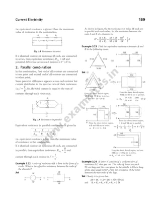
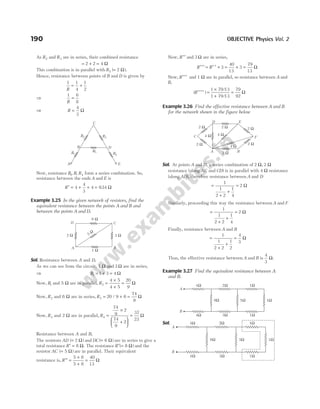
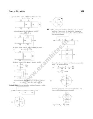
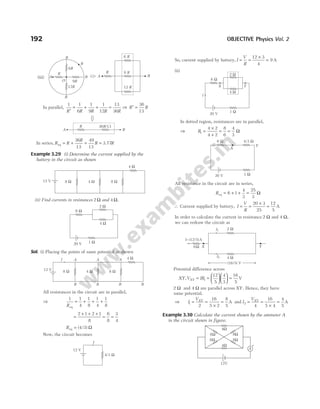
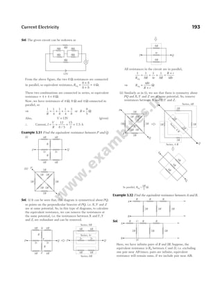
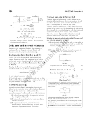
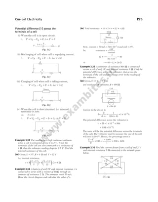
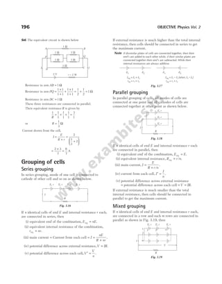
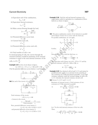
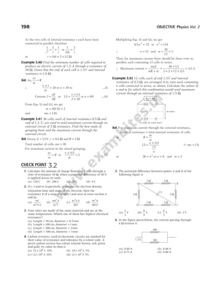
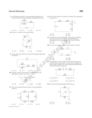
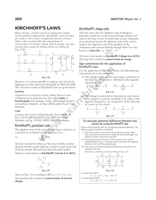
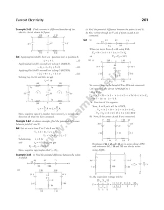
![∴ Potential difference between points A and B,
V V
A B
− =
55
7
V
For cell of emf 20 V,
V V i
A B
− = −
20 5 1
55
7
20 5 1
= − i ⇒ 5 20
55
7
12
1
i = − −
~ A
∴Current through cell of 20 V, i1 2 4
= . A
Electrical energy and power
Electrical energy and power in electrical circuits or
components are described below.
Electrical energy
It is defined as the total work doneW by the source of emf
V in maintaining the electric current I in the circuit for a
specified time t.
According to Ohm’s law, we haveV IR
=
Total charge that crosses the resistor is given by q It
=
Energy gained is given by E W Vq
= = =VIt
= =
( )
IR I R t
It 2
[ ]
QV IR
=
=
=
V
R
2
Rt
V t
R
2
QI
V
R
=
The SI unit of electrical energy is joule (J), where
1 joule = 1volt × 1ampere × 1second = 1watt × 1second.
Electrical Power
It is defined as the rate of electrical energy supplied
per unit time to maintain the flow of electric current
through a conductor.
Mathematically, P
W
t
VI I R
= = = 2
=
V
R
2
The SI unit of power is watt (W), where
1 watt = ×
1 volt 1 ampere =1ampere-volt.
It can be defined as, the power of an electric circuit is
called one watt, if one ampere current flows in it against
a potential difference of one volt. The bigger units of
electrical power are kilowatt (kW) and megawatt (MW)
where,1kW 1000 W and
= 1 MW 106
= W.
Commercial unit of electrical power is horse power (HP),
where,1 746
HP = W.
Heating effects of current
An electric current through a resistor increases its thermal
energy. Also, there are other situations in which an
electric current can produce or absorb thermal energy.
This effect is called heating effect of electric current.
When some potential differenceV is applied across a
resistance R, charge q flows through the circuit in time t,
then the heat absorbed or produced is given by
W qV
= = Vit = =
i Rt
V t
R
2
2
joule
or W
Vit
J
i Rt
J
V t
JR
= = =
2 2
cal
where, J is the joule’s mechanical equivalent of heat
(4.21 J/cal).
These relations are also called Joule’s law of heating.
Example 3.46 In the given network of resistors, find the heat
developed across each resistance in 2s.
Sol. The 6 Ω and 3 Ω resistances are in parallel. So, their
combined resistance is
1 1
6
1
3
1
2
R
= + = or R = Ω
2
The equivalent simple circuit can be drawn as shown.
Current in the circuit,
i =
Net emf
Total resistance
=
+ +
20
3 2 5
= 2 A
V iR
= = =
( ) ( )
2 2 4 V
i.e. potential difference across 6 Ω and 3 Ω resistances same
as 4 V. Now,
H i Rt
3
2 2
2 3 2
Ω = = =
( ) ( ) ( ) 24 J
H
V
R
t
6
2 2
4
6
2
Ω = = =
( )
( )
16
3
J
H
V
R
t
3
2 2
4 2
3
Ω = = =
( ) ( ) 32
3
J
and H i Rt
5
2 2
2 5 2
Ω = = =
( ) ( ) ( ) 40 J
202 OBJECTIVE Physics Vol. 2
20 V
6 Ω
3 Ω
3 Ω
5 Ω
3Ω 2Ω
5Ω
20 V
20 V
2 W
3 W
5 W
V
i](https://image.slidesharecdn.com/arihantneetobjectivephysicsvolume2bydcpandey2022edition-230417145135-9bce7664/85/Arihant_NEET_Objective_Physics_Volume_2_By_DC_Pandey_2022_Edition-pdf-213-320.jpg)
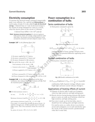
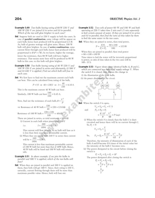
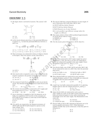
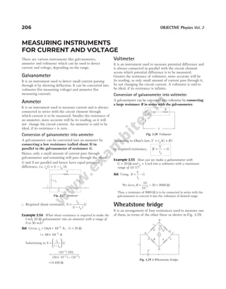
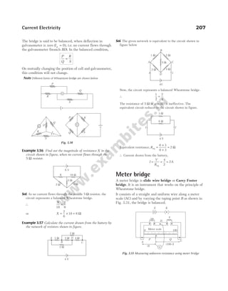
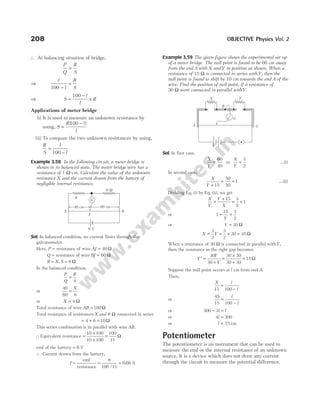
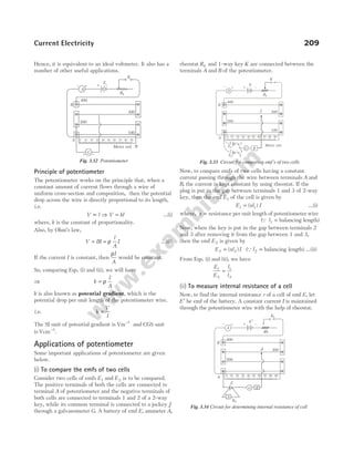
![Now, the plug in key K2 is kept out and the jockey J is
moved on the potentiometer wire to balance the emf E of
the cell, whose internal resistance r is to be determined.
Suppose l1 be the balancing length of the potentiometer
wire between point A and jockey J. If x is resistance per
unit length of wire, then emf of cell is given by
E xl I
= 1 …(i)
Introduce some resistance, says S from the resistance box S
and now put in the plug key K2. The potential difference
V between the two terminals of the cell is given by
V xl I
= 2 …(ii)
[Q l2 = balancing length]
On dividing Eq. (i) by Eq. (ii), we have
E
V
l
l
= 1
2
The internal resistance of the cell is given by r
E
V
S
= −
1
Now, substituting values of E V
/ in above equation, we get
⇒ r
l
l
S
= −
1
2
1
where, S is the resistance of the resistance box.
Note
(i) The sensitiveness of potentiometer means the smallest potential
difference that can be measured with its help.
(ii) A potentiometer can also be used to compare unknown resistances
and to calibrate a voltmeter or an ammeter.
(iii) A balance point is obtained on the potentiometer wire, if the fall of
potential along the potentiometer wire due to driving cell is greater
than the emf of the cell to be balanced.
Example 3.60 A potentiometer wire is 10 m long and has a
resistance of 18 Ω. It is connected to a battery of emf 5V
and internal resistance 2 Ω. Calculate the potential gradient
along the wire.
Sol. Given, l = 10 m , R = 18 Ω, E = 5 V and r = 2 Ω
Current through the potentiometer wire,
I
E
R r
=
+
=
+
= =
5
18 2
5
20
1
4
A
∴ Potential gradient = = × = −
IR
l
1
4
18
10
1
0.45Vm
Example 3.61 A cell can be balanced against 110 cm and
100 cm of potentiometer wire respectively, when in open
circuit and when short circuited through a resistance of
10 Ω. Find the internal resistance of the cell.
Sol. Given, l1 110
= cm, l2 100
= cm, R = 10 Ω and r = ?
∴ r
l l
l
R
=
−
1 2
2
⇒ r =
−
× =
110 100
100
10 1Ω
Example 3.62 In a potentiometer arrangement, a cell of emf
2.25V gives a balance point at 30.0 cm length of the wire.
If the cell is replaced by another cell and the balance point
shifts to 60.0 cm, then what is the emf of the second cell?
Sol. Given, E1 = 2.25 V, l1 = 30.0 cm,
l 2 = 60.0 cm and E2 = ?
As we know that in case of potentiometer, the potential
gradient remains constant.
So, E l
∝
∴
E
E
l
l
1
2
1
2
=
⇒
2.25 30.0
E2 60 0
=
.
∴ E2
60
30
4 5
=
×
=
2.25
V
.
Example 3.63 AB is 1 m long uniform wire of 10 Ω
resistance. Other data are as shown in figure. Calculate (i)
potential gradient along AB and (ii) length AO, when
galvanometer shows no deflection.
Sol. (i) Total resistance of the primary circuit
= + =
15 10 25 Ω and emf V
= 2
∴ Current in the wire AB,
I = =
2
25
0.08 A
Potential difference across the wire AB
= ×
Current Resistance of wire AB
= × =
0.08 0.8 V
10
Potential gradient
= = = −
Potential difference
Length
0.008 V cm
0 8
100
1
.
(ii) Resistance of secondary circuit = + =
1.2 0.3 1.5 Ω
emf 1.5V
=
Current in the secondary circuit = =
1.5
1.5
1.0A
The same current is flowing in 0.3 Ω resistor.
Potential difference between points A and O
= Potential difference across 0.3 Ω resistor in the zero
deflection condition
= Current × Resistance = × =
1.0 0.3 0.3 V
Length AO =
Potential difference
Potential gradient
= =
−
0.3
0.008 V cm
37.5 cm
V
1
210 OBJECTIVE Physics Vol. 2
2V 15W
1.5V
0.3W
1.2W
G
B
A
O](https://image.slidesharecdn.com/arihantneetobjectivephysicsvolume2bydcpandey2022edition-230417145135-9bce7664/85/Arihant_NEET_Objective_Physics_Volume_2_By_DC_Pandey_2022_Edition-pdf-221-320.jpg)
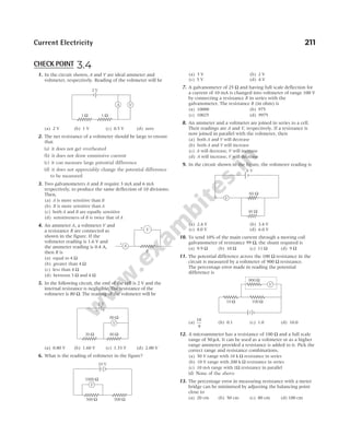
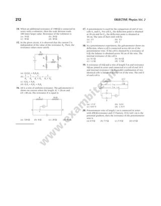
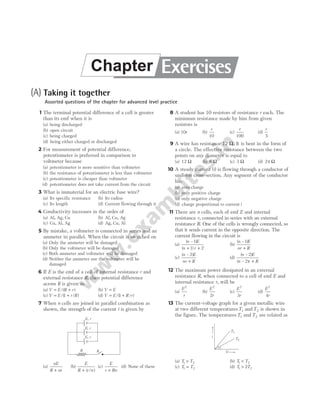
![14 Which of the following characteristics of electrons
determines the current in a conductor?
[NCERT Exemplar]
(a) Drift velocity only
(b) Thermal velocity only
(c) Both drift velocity and thermal velocity
(d) Neither drift nor thermal velocity
15 An ammeter and a voltmeter of resistance R are
connected in series to an electric cell of negligible
internal resistance. Their readings are A and V,
respectively. If another resistance R is connected in
parallel with the voltmeter, then potential across
(a) Both A and V will increase
(b) Both A and V will decrease
(c) A will decrease and V will increase
(d) A will increase and V will decrease
16 The resistance of a wire is 10 Ω. Its length is
increased by 10% by stretching. The new resistance
will be
(a) 12 Ω (b) 1.2 Ω (c) 13 Ω (d) 11 Ω
17 Four resistances are connected in a circuit as shown
in the given figure. The electric current flowing
through 4 Ω and 6 Ω resistance is respectively
(a) 2 A and 4 A (b) 1 A and 2 A
(c) 1 A and 1 A (d) 2 A and 2 A
18 Current through the 5 Ω resistor is
(a) 2A (b) 4A
(c) zero (d) 1A
19 A cell which has an emf of 1.5 V is connected in
series with an external resistance of 10 Ω. If the
potential difference across the cell is 1.25 V, then
the internal resistance of the cell (in Ω) is
(a) 2 (b) 0.25 (c) 1.5 (d) 0.3
20 A piece of wire of resistance 4 Ω is bent through
180° at its mid-point and the two halves are twisted
together, then the resistance is
(a) 8 Ω (b) 1 Ω (c) 2 Ω (d) 5 Ω
21 A wire of resistance R is divided into 10 equal parts.
These parts are connected in parallel, the equivalent
resistance of such connection will be
(a) 0.01 R (b) 0.1 R
(c) 10 R (d) 100 R
22 Three resistors each of 2 Ω are connected together
in a triangular shape. The resistance between any
two vertices will be
(a) 4/3 Ω (b) 3/4 Ω (c) 3 Ω (d) 6 Ω
23 The effective resistance between the points A and B
in the figure is
(a) 5 Ω (b) 2 Ω (c) 3 Ω (d) 4 Ω
24 Two resistances are joined in parallel whose
resultant is
6
8
Ω. One of the resistance wire is broken
and the effective resistance becomes 2 Ω. Then, the
resistance in ohm of the wire that got broken was
(a) 3/5 (b) 2 (c) 6/5 (d) 3
25 A wire of resistance 9Ω is broken in two parts. The
length ratio being 1 : 2. The two pieces are
connected in parallel. The net resistance will be
(a) 2 Ω (b) 3 Ω (c) 4 Ω (d) 6 Ω
26 In the network shown, the equivalent resistance
between A and B is
(a)
4
3
Ω (b)
3
4
Ω (c)
24
17
Ω (d)
17
24
Ω
27 To send 10% of main current through a moving coil
galvanometer of resistance 99 Ω, shunt required is
(a) 9 Ω (b) 11 Ω
(c) 10 Ω (d) 9.9 Ω
28 A 1250 W heater operates at 115 V. What is the
resistance of the heating coil?
(a) 1.6 Ω (b) 13.5 Ω
(c) 1250 Ω (d) 10.6 Ω
214 OBJECTIVE Physics Vol. 2
5 Ω 10 V
10 V
4 Ω 6 Ω
4 Ω 6 Ω
20 V
3 Ω
3 Ω
3 Ω
3 Ω
6 Ω
D
B
A C
4 Ω
8 Ω
3 Ω
2 Ω 6 Ω
6 Ω
B
A](https://image.slidesharecdn.com/arihantneetobjectivephysicsvolume2bydcpandey2022edition-230417145135-9bce7664/85/Arihant_NEET_Objective_Physics_Volume_2_By_DC_Pandey_2022_Edition-pdf-225-320.jpg)
![29 The resistance of a wire at 20°C is 20 Ω and at
500°C is 60 Ω. At which temperature its resistance
will be 25Ω?
(a) 50°C (b) 60°C (c) 70°C (d) 80°C
30 A conducting wire of cross-sectional area1 cm2
has
3 1023
× charge carriers per metre3
. If wire carries a
current 24 mA, then drift velocity of carriers is
(a) 5 10 ms
2 1
× − −
(b) 0.5 ms 1
−
(c) 5 10 ms
3 1
× − −
(d) 5 10 ms
6 1
× − −
31 At room temperature, copper has free electron
density of 8.4 10 m
28 3
× −
. The electron's drift
velocity in a copper conductor of cross-sectional area
of10 m
6 2
−
and carrying a current of 5.4 A, will be
(a) 4 ms 1
−
(b) 0.4 ms 1
−
(c) 4 cms 1
−
(d) 0.4 mms 1
−
32 A metal rod of length 10 cm and a rectangular
cross-section of 1cm × (1/2) cm is connected to a
battery across opposite faces. The resistance will be
[NCERT Exemplar]
(a) maximum when the battery is connected across
1 1 2
cm × ( / ) cm faces
(b) maximum when the battery is connected across
10 cm 1) cm
× ( faces
(c) maximum when the battery is connected across
10 cm (1/2 cm
× ) faces
(d) same irrespective of the three faces
33 Two cells of emfs approximately 5V and 10V are to
be accurately compared using a potentiometer of
length 400 cm. [NCERT Exemplar]
(a) The battery that runs the potentiometer should have
voltage of 8V
(b) The battery of potentiometer can have a voltage of
15 V and R adjusted so that the potential drop across
the wire slightly exceeds 10 V
(c) The first portion of 50 cm of wire itself should have a
potential drop of 10 V
(d) Potentiometer is usually used for comparing resistances
and not voltages
34 The resistivity of a potentiometer wire is
40 10 8
× −
Ω-m and its area of cross-section is
8 10 6 2
× −
m . If 0.2 A current is flowing through the
wire, the potential gradient will be
(a) 10 2
−
V/m (b) 10 1
−
V/m
(c) 3.2 V/m
× −
10 2
(d) 1 V/m
35 Two cells of emfs E1 and E E E
2 1 2
( )
> are connected
as shown in figure.
When a potentiometer is connected between A and
B, the balancing length of the potentiometer wire is
300 cm. On connecting the same potentiometer
between A and C, the balancing length is 100 cm.
The ratio
E
E
1
2
is
(a) 3 : 1 (b) 1 : 3
(c) 2 : 3 (d) 3 : 2
36 A voltmeter of resistance 998 Ω is connected across
a cell of emf 2 V and internal resistance 2 Ω. The
potential difference across the voltmeter is
(a) 1.99 V (b) 3.5 V
(c) 5 V (d) 6 V
37 A wire 50 cm long and 1 mm2
in cross-section
carries a current of 4 A when connected to a 2 V
battery. The resistivity of the wire is
(a) 2 10 7
× −
Ω-m (b) 5 10 7
× −
Ω-m
(c) 4 10 6
× −
Ω-m (d) 1 10 6
× −
Ω-m
38 Three resistances P Q R
, , each of 2Ω and an
unknown resistance S form the four arms of a
Wheatstone’s bridge circuit. When a resistance of
6Ω is connected in parallel to S, the bridge gets
balanced. What is the value of S ?
(a) 2 Ω (b) 3 Ω
(c) 6 Ω (d) 1Ω
39 A 2 V battery, a 990 Ω resistor and a potentiometer
of 2 m length, all are connected in series. If the
resistance of potentiometer wire is 10 Ω, then the
potential gradient of the potentiometer wire is
(a) 0.05 Vm 1
−
(b) 0.5 Vm 1
−
(c) 0.01 Vm 1
−
(d) 0.1 Vm 1
−
40 The electron with charge q = × −
1.6 10 C)
19
( moves in
an orbit of radius 5 10 m
11
× −
with a speed of
2.2 10 ms
6 1
× −
, around an atom. The equivalent
current is
(a) 1.12 10 A
6
× −
(b) 1.12 10 A
3
× −
(c) 1.12 10 A
9
× −
(d) 1.12 A
41 A potentiometer having the potential gradient of
2 mV/cm is used to measure the difference of
potential across a resistance of 10 Ω in same circuit.
If a length of 50 cm of the potentiometer wire is
required to get the null point, then the current
passing through the 10 Ω resistor is (in mA)
(a) 1 (b) 2 (c) 5 (d) 10
42 The n rows each containing m cells in series are
joined in parallel. Maximum current is taken from
this combination across an external resistance of
3 Ω. If the total number of cells used are 24 and
internal resistance of each cell is 0.5 Ω, then
(a) m n
= =
8, 3 (b) m n
= =
6, 4
(c) m n
= =
1 2
2, (d) m n
= =
2, 12
Current Electricity 215
A
B
C
E1 E2](https://image.slidesharecdn.com/arihantneetobjectivephysicsvolume2bydcpandey2022edition-230417145135-9bce7664/85/Arihant_NEET_Objective_Physics_Volume_2_By_DC_Pandey_2022_Edition-pdf-226-320.jpg)
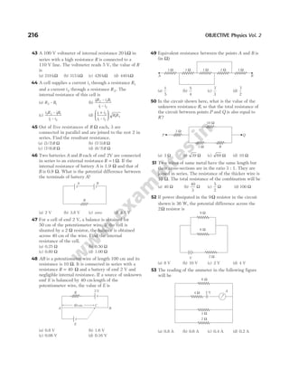
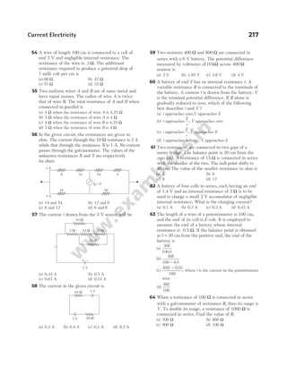
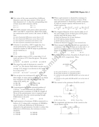
![(a)
7
3
A from a to e (b)
7
3
A from b to e
(c) 1A from b to e (d) 1A from a to e
79 Consider a current carrying wire (current I) in the
shape of a circle. Note that as the currrent progresses
along the wire, the direction of J (current density)
changes in an exact manner, while the current I
remains unaffected. The agent that is essentially
responsible for [NCERT Exemplar]
(a) source of emf
(b) electric field produced by charges accumulated on the
surface of wire
(c) the charges just behind a given segment of wire which
push them just the right way by repulsion
(d) the charges ahead
80. Two batteries of emf ε1 and ε ε >ε
2 2 1
( ) and internal
resistances r1 and r2 respectively are connected in
parallel as shown in figure. [NCERT Exemplar]
(a) The equivalent emf εeq of the two cells is between ε1
and ε2, i.e. ε ε ε
1 2
< <
eq
(b) The equivalent emf εeq is smaller than ε1
(c) The εeq is given by ε ε ε
eq = +
1 2 always
(d) εeq is independent of internal resistances r1 and r2
81 A resistance R is to be measured using a meter
bridge, student chooses the standard resistance S to
be100 Ω. He finds the null point at l1 29
= . cm. He
is told to attempt to improve the accuracy.
Which of the following is a useful way?
[NCERT Exemplar]
(a) He should measure l1 more accurately
(b) He should change S to1000 Ω and repeat the
experiment
(c) He should change S to 3 Ω and repeat the experiment
(d) He should given up hope of a more accurate
measurement with a meter bridge
82 The current drawn from the battery shown in the
figure is
(a)
V
R
(b)
V
R
2
(c)
2
V
R
(d)
3
2
V
R
83 In the below circuit, the battery E1 has an emf of 12 V
and zero internal resistance. While the battery E2 has
an emf of 2 V.
If the galvanometer G reads zero, then the value of
the resistance X in ohms is
(a) 250 (b) 100
(c) 50 (d) 200
84 The potential drop across the 3 Ω resistor is
(a) 1 V (b) 1.5 V
(c) 2 V (d) 3 V
85 Equivalent resistance between A and B will be
(a) 2 Ω (b) 18 Ω
(c) 6 Ω (d) 3.6 Ω
86 In the network of resistors shown in the figure, the
equivalent resistance between A and B is
(a) 54 Ω (b) 18 Ω
(c) 36 Ω (d) 9 Ω
Current Electricity 219
ε1
ε2
r1
r2
A B
V
R
R
R
G
500 Ω
E1 E2
X Ω
3 Ω
6 Ω
4 Ω
3 V
3 Ω 3 Ω
3 Ω 3 Ω
3 Ω 3 Ω
3 Ω 3 Ω
A B
3Ω
3Ω 3Ω 3Ω 3Ω 3Ω 3Ω
3Ω 3Ω 3Ω 3Ω 3Ω
A B](https://image.slidesharecdn.com/arihantneetobjectivephysicsvolume2bydcpandey2022edition-230417145135-9bce7664/85/Arihant_NEET_Objective_Physics_Volume_2_By_DC_Pandey_2022_Edition-pdf-230-320.jpg)
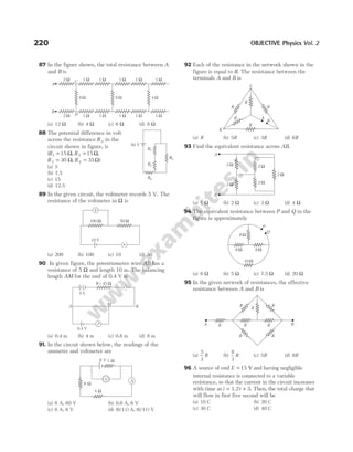
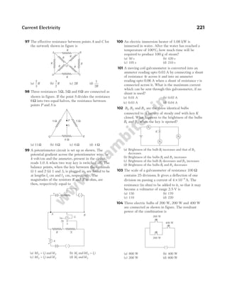
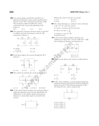
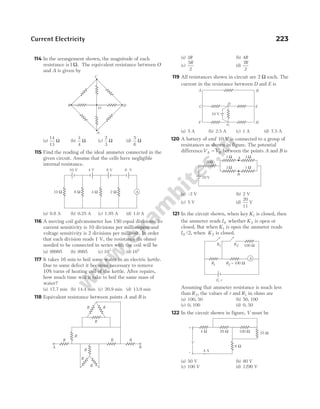
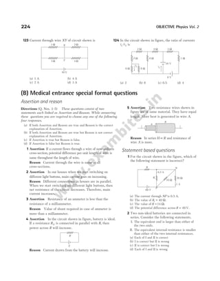
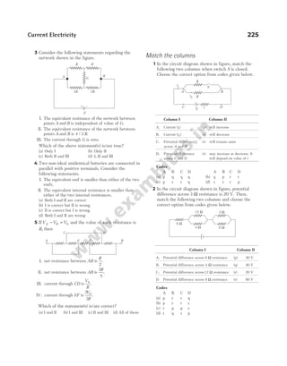
![(C) Medical entrances’ gallery
Collection of questions asked in NEET and various medical entrance exams
1 A charged particle having drift velocity of
75 10 4
. × −
ms−1
in an electric field of
3 10 10
× −
Vm−1
, has a mobility (in m2
V−1
s−1
) of
[NEET 2020]
(a) 2 5 106
. × (b) 2 5 10 6
. × −
(c) 225 10 15
. × −
(d) 225 1015
. ×
2 The color code of a resistance is given below
The values of resistance and tolerance respectively,
are [NEET 2020]
(a) 47 kΩ, 10% (b) 4.7 kΩ, 5%
(c) 470 Ω, 5% (d) 470 kΩ, 5%
3 A resistance wire connected in the left gap of a
metre bridge balances a 10 Ω resistance in the right
gap at a point which divides the bridge wire in the
ratio 3 : 2. If the length of the resistance wire is
1.5 m, then the length of 1 Ω of the resistance wire
is [NEET 2020]
(a)10 10 1
. × −
m (b)15 10 1
. × −
m
(c)15 10 2
. × −
m (d)10 10 2
. × −
m
4 Which of the following graph represents the
variation of resistivity (ρ) with temperature ( )
T for
copper? [NEET 2020]
5 For the circuit shown in the figure, the current I will
be [NEET 2020]
(a) 0.75 A (b) 1 A
(c) 1.5 A (d) 0.5 A
6 Two solid conductors are made up of same material,
have same length and same resistance. One of them has
a circular cross-section of area A1 and the other one
has a square cross-section of area A2. The ratio
A A
1 2
/ is [NEET 2020]
(a) 1.5 (b) 1 (c) 0.8 (d) 2
7 For the circuit given below, the Kirchhoff’s loop rule
for the loop BCDEB is given by the equation
[NEET 2020]
(a) − + − + =
i R E E i R
2 2 2 3 3 1 0
(b) i R E E i R
2 2 2 3 3 1 0
+ − − =
(c) i R E E i R
2 2 2 3 3 1 0
+ + + =
(d) − + + + =
i R E E i R
2 2 2 3 3 1 0
8 The equivalent resistance between A and B for the
mesh shown in the figure is [NEET 2020]
(a) 72
. Ω (b)16 Ω (c) 30 Ω (d) 4 8
. Ω
9 Six similar bulbs are connected as shown in the
figure with a DC source of emf E and zero internal
resistance.
The ratio of power consumption by the bulbs when
(i) all are glowing and (ii) in the situation when two
from section A and one from section B are glowing,
will be [NEET 2019]
(a) 9 : 4 (b) 1 : 2 (c) 2 : 1 (d) 4 : 9
OBJECTIVE Physics Vol. 2
(a) (b)
(c) (d)
ρ
T T
T T
ρ
ρ ρ
2 V 1 Ω 4 V 1 Ω
4 Ω
I
A B C
F E D
R2 i2
i1
i3
R1
E1 E2
E3
4 Ω 8 Ω
8 Ω
4 Ω
A B
6 Ω
Yellow Violet Brown Gold
A B
E](https://image.slidesharecdn.com/arihantneetobjectivephysicsvolume2bydcpandey2022edition-230417145135-9bce7664/85/Arihant_NEET_Objective_Physics_Volume_2_By_DC_Pandey_2022_Edition-pdf-237-320.jpg)
![10 Which of the following acts as a circuit protection
device? [NEET 2019]
(a) Inductor (b) Switch (c) Fuse (d) Conduct
11 In the circuits shown below, the readings of
voltmeters and the ammeters will be [NEET 2019]
(a)V V
1 2
= and i i
1 2
> (b)V V
1 2
= and i i
i = 2
(c)V V
2 1
> and i i
1 2
> (d)V V
2 1
> and i i
1 2
=
12 The meter bridge shown in the balance position with
P
Q
l
l
= 1
2
. If we now interchange the positions of
galvanometer and cell, will the bridge work? If yes,
that will be balanced condition? [NEET (Odisha) 2019]
(a) Yes,
P
Q
l l
l l
=
−
+
2 1
2 1
(b) No, no null point
(c) Yes,
P
Q
l
l
= 2
1
(d) Yes,
P
Q
l
l
= 1
2
13 The reading of an ideal voltmeter in the circuit
shown is [NEET (Odisha) 2019]
(a) 0.6 V (b) 0 V (c) 0.5 V (d) 0.4 V
14 For a wire
R
l
=
1
2
and length of wire is l = 5 cm.
If potential difference of 1 V is applied across it,
then current through wire will be [AIIMS 2019]
(a) 40 A (b) 4 A (c) 25 A (d) 2.5 A
15 A current of 10 A is passing through a metallic wire
of cross-sectional area 4 10 6
× −
m2
. If the density of
the aluminium conductor is 2.7 g/cc, considering
aluminium gives 1 electron per atom for conduction,
then find the drift velocity of the electrons if
molecular weight of aluminium is 27 g. [AIIMS 2019]
(a)16 10 4
. × −
m/s (b) 3 6 10 4
. × −
m/s
(c) 2 6 10 4
. × −
m/s (d)15 10 4
. × −
m/s
16 A circuit contain two resistances R1and R2 are in
series. Find the ratio of input voltage to voltage of
R2. [JIPMER 2019]
(a)
R
R R
2
1 2
+
(b)
R R
R
1 2
2
+
(c)
R R
R
1 2
1
+
(d)
R
R R
1
1 2
+
17 In the given circuit, find voltage across 12 Ω
resistance. [JIPMER 2019]
(a) 12 V (b) 36 V (c) 72 V (d) 48 V
18 Find the current in the 8Ω resistance in the given
circuit. [JIPMER 2019]
(a) 2 A (b) 3A
(c) 4 A (d) 5 A
19 If resistivity of copper is172 10 8
. × −
Ω-m and
number of free electrons in copper is
85 1028 3
. /
× m . Find the mobility. [JIPMER 2019]
(a) 4 25 10 3 2
. /
× −
m CΩ (b) 6 8 10 3 2
. /
× −
m CΩ
(c) 8 5 10 3 2
. /
× −
m CΩ (d) 3 4 10 3 2
. /
× −
m CΩ
Current Electricity 227
3W 3W
3W
3W
3W
8W
24 V
20 Ω 30 Ω
30 Ω 20 Ω
V
2 V
10 Ω
V1
A1
10 V
i1 10 Ω
10 Ω
V2 A2
10 V
i2
P Q
G
l1 l2
8Ω
8Ω
4Ω
4Ω
12A
12Ω](https://image.slidesharecdn.com/arihantneetobjectivephysicsvolume2bydcpandey2022edition-230417145135-9bce7664/85/Arihant_NEET_Objective_Physics_Volume_2_By_DC_Pandey_2022_Edition-pdf-238-320.jpg)
![20 In the given circuit, if power rating of heater is
1000 W at 100 V, find the resistance R in figure so
that heater produces power of 62.5 W. [JIPMER 2019]
(a) 5 Ω (b) 7 Ω (c) 10 Ω (d) 8 Ω
21 A carbon resistor of (47 4.7) k
± Ω is to be marked
with rings of different colours for its identification.
The colour code sequence will be [NEET 2018]
(a) Yellow - Green - Violet - Gold
(b) Yellow - Violet - Orange - Silver
(c) Violet - Yellow - Orange - Silver
(d) Green - Orange - Violet - Gold
22 A set of n equal resistors, of value R each , are
connected in series to a battery of emf E and internal
resistance R. The current drawn is I. Now, the n
resistors are connected in parallel to the same
battery. Then, the current drawn from battery
becomes10I. The value of n is [NEET 2018]
(a) 20 (b) 11 (c) 10 (d) 9
23 A battery consists of a variable number n of identical
cells (having internal resistance r each) which are
connected in series. The terminals of the battery are
short-circuited and the current I is measured. Which
of the graphs shows the correct relationship between
I and n? [NEET 2018]
24 Find current ( )
i in circuit shown in figure.[NEET 2018]
(a) 0.5 A (b) 0.2 A
(c) 1 A (d) 2 A
25 Assertion Terminal voltage of a cell is greater than
emf of cell during charging of the cell. [AIIMS 2018]
Reason The emf of a cell is always greater than its
terminal voltage.
(a) Both Assertion and Reason are correct and Reason is the
correct explanation of Assertion.
(b) Both Assertion and Reason are correct but Reason is not
the correct explanation of Assertion.
(c) Assertion is correct but Reason is incorrect.
(d) Assertion is incorrect but Reason is correct.
26 The effective resistance between P and Q in given
figure is [AIIMS 2018]
(a) 2Ω (b) 3Ω (c) 5Ω (d) 6Ω
27 Assertion Bulb generally get fused when they are
switched ON or OFF.
Reason When we switch ON or OFF a circuit,
current changes in it rapidly. [AIIMS 2018]
(a) Both Assertion and Reason are correct and Reason is the
correct explanation of Assertion.
(b) Both Assertion and Reason are correct but Reason is not
the correct explanation of Assertion.
(c) Assertion is correct and Reason is incorrect.
(d) Assertion is incorrect and Reason is correct.
28 A current i is flowing through the wire of diameter
d having drift velocity of electrons v d in it. What
will be new drift velocity when diameter of wire is
made d/4? [JIPMER 2018]
(a) 4vd (b)
vd
4
(c)16vd (d)
vd
16
29 The resistance of a wire is R ohm. If it is melted and
stretched to n times its original length, its new
resistance will be [NEET 2017]
(a) nR (b)
R
n
(c) n R
2
(d)
R
n2
30 Find the value of R net between A and B. [NEET 2017]
(a) 60 Ω (b) 40 Ω (c) 70 Ω (d) 20 Ω
228 OBJECTIVE Physics Vol. 2
(a) (b)
(c) (d)
I
I
I
I
n n
n n
O
O
O
O
10W
5W
10W
10W 20W
C
B
D
A
5V
i
P Q
6W 8W
8W
3W
10W
10W
20W
4
W
4W
5W
4W
10W
100 V
Heater
R
A
B
10W 10W 10W
40W 40W 20W
10W 10W 10W](https://image.slidesharecdn.com/arihantneetobjectivephysicsvolume2bydcpandey2022edition-230417145135-9bce7664/85/Arihant_NEET_Objective_Physics_Volume_2_By_DC_Pandey_2022_Edition-pdf-239-320.jpg)
![31 FindV V
P Q
− in the circuit shown in below figure.
[NEET 2017]
(a) 6.68 V (b) 8 V (c) 4.65 V (d) 7 V
32 Find the value of i in shown below figure. [NEET 2017]
(a) 0.2A (b) 0.1A (c) 0.3A (d) 0.4A
33 N lamps each of resistance r are fed by a machine
of resistance R. If light emitted by any lamp is
proportional to the square of the heat produced,
prove that the most efficient way of arranging them
is to place them in parallel arcs, each containing n
lamps, where n is the integer nearest to [NEET 2017]
(a)
r
NR
3 2
/
(b)
NR
r
1 2
/
(c) ( ) /
NRr 3 2
(d) ( ) /
NRr 1 2
34 Two batteries, one of emf 18V and internal
resistance 2Ω and the other of emf 12V and internal
resistance1Ω are connected as shown in figure. The
voltmeterV will record a reading of [AIIMS 2017]
(a)14 V (b)15 V (c)18 V (d) 30 V
35 Assertion A potentiometer is preferred over that of
a voltmeter for measurement of emf of a cell.
Reason Potentiometer does not draw any current
from the cell. [AIIMS 2017]
(a) Both Assertion and Reason are correct and Reason is the
correct explanation of Assertion.
(b) Both Assertion and Reason are correct but Reason is not
the correct explanation of Assertion.
(c) Assertion is correct Reason is incorrect.
(d) Assertion is incorrect but Reason incorrect.
36 You are given resistance wire of length 50 cm and a
battery of negligible resistance. In which of the
following cases is largest amount of heat generated?
[JIPMER 2017]
(a) When the wire is connected to the battery directly.
(b) When the wire is divided into two parts and both the
parts are connected to the battery in parallel.
(c) When the wire is divided into four parts and all the
four parts are connected to the battery in parallel.
(d) When only half of the wire is connected to the
battery.
37 The current passing through the ideal ammeter in
the circuit given below is [KCET 2017]
(a)1.25A (b) 1A (c) 0.75A (d) 0.5 A
38 A potentiometer wire is 100 cm long and a constant
potential difference is maintained across it. Two
cells are connected in series first to support one
another and then in opposite direction. The balance
points are obtained at 50 cm and 10 cm from the
positive end of the wire in the two cases. The ratio
of emfs is [NEET 2016]
(a) 5 : 4 (b) 3 : 4 (c) 3 : 2 (d) 5 : 1
39 The charge flowing through a resistance R varies
with time t as Q at bt
= − 2
, where a and b are
positive constants. The total heat produced in R is
[NEET 2016]
(a)
a R
b
3
3
(b)
a R
b
3
2
(c)
a R
b
3
(d)
a R
b
3
6
40 The potential difference ( )
V V
A B
− between the
points A and B in the given figure is [NEET 2016]
(a) –3 V (b) +3 V (c) +6 V (d) +9 V
41 A filament bulb (500 W, 100 V) is to be used in a
230 V main supply. When a resistance R is
connected in series, it works perfectly and the bulb
consumes 500 W. The value of R is [NEET 2016]
(a) 230 Ω (b) 46 Ω
(c) 26 Ω (d) 13 Ω
Current Electricity 229
2 Ω
2 Ω
4 V
A
2 Ω
4 Ω
1 Ω
V
1Ω
2Ω
18V
12V
+ –
3 V
1 W VB
B
VA 2 W
I = 2 A
30 Ω
60 Ω
i1
i2
i
2V
Q
10W
8W
18W
25W
10W
R
+ –
P
10 V](https://image.slidesharecdn.com/arihantneetobjectivephysicsvolume2bydcpandey2022edition-230417145135-9bce7664/85/Arihant_NEET_Objective_Physics_Volume_2_By_DC_Pandey_2022_Edition-pdf-240-320.jpg)
![42 A potentiometer wire has length 4 m and resistance
8 Ω. The resistance that must be connected in series
with the wire and an accumulator of emf 2 V, so as
to get a potential gradient of 1 mV per cm on the
wire is [CBSE AIPMT 2015]
(a) 32 Ω (b) 40 Ω (c) 44 Ω (d) 48 Ω
43 A B
, and C are voltmeters of resistance R R
, 1.5 and
3R respectively, as shown in the figure. When some
potential difference is applied between X andY, then
the voltmeter readings areV V
A B
, andVC ,
respectively. Then, [CBSE AIPMT 2015]
(a) V V V
A B C
= = (b) V V V
A B C
≠ =
(c) V V V
A B C
= ≠ (d) V V V
A B C
≠ ≠
44 Across a metallic conductor of non-uniform
cross-section, a constant potential difference is
applied. The quantity which remain(s) constant along
the conductor is [CBSE AIPMT 2015]
(a) current density (b) current
(c) drift velocity (d) electric field
45 Consider the diagram shown below [AIIMS 2015]
A voltmeter of resistance 150 Ω is connected across
A and B. The potential drop across B and C measured
by voltmeter is
(a) 29 (b) 27 V (c) 31 V (d) 30 V
46 Each resistor shown in the figure has a resistance of
10 Ω and the battery has the emf 6 V. What will be
the current supplied by the battery? [UK PMT 2015]
(a) 0.6 A (b) 1.2 A (c) 1.8 A (d) 0.3 A
47 A 1Ω resistance in series with an ammeter is
balanced by 75 cm of potentiometer wire. A
standard cell of emf 1.02 V is balanced by 50 cm.
The ammeter shows a reading of 1.5 A. Then, the
error in ammeter reading is [EAMCET 2015]
(a) 0.03 A (b) 3A (c) 1.3 A (d) 0.3 A
48 The range of voltmeter is 10 V and its internal
resistance is 50 Ω. To convert it to a voltmeter of
range 15 V, how much resistance is to be added?
(a) Add 25 Ω resistor in parallel [EAMCET 2015]
(b) Add 25 Ω resistor in series
(c) Add125 Ω resistor in parallel
(d) Add125 Ω resistor in series
49 Identify the wrong statement. [Kerala CEE 2015]
(a) Charge is a vector quantity
(b) Current is a scalar quantity
(c) Charge can be quantised
(d) Charge is additive in nature
(e) Charge is conserved
50 When the rate of flow of charge through a metallic
conductor of non-uniform cross-section is uniform,
then the quantity that remains constant along the
conductor is [Kerala CEE 2015]
(a) current density (b) electric field
(c) electric potential (d) drift velocity
(e) current
51 The resistance of a carbon resistor of colour code
Red-Red-Green-Silver is (in kΩ) [Kerala CEE 2015]
(a) 2200 5
± % (b) 2200 10
± %
(c) 220 10
± % (d) 220 5
± %
(e) 2200 1
± %
52 The slope of the graph showing the variation of
potential differenceV on X-axis and current on
Y-axis gives conductor [Kerala CEE 2015]
(a) resistance (b) resistivity
(c) reciprocal of resistance (d) conductivity
(e) impedance
53 Two wires of equal length and equal diameter and
having resistivities ρ1 and ρ2 are connected in series.
The equivalent resistivity of the combination is
[Guj. CET 2015]
(a)
ρ ρ
1 2
2
+
(b) ρ ρ
1 2
+
(c)
ρ ρ
ρ ρ
1 2
1 2
+
(d) ρ ρ
1 2
54 A galvanometer of resistance 50 Ω is connected to a
battery of 8 V along with a resistance of 3950 Ω in
series. A full scale deflection of 30 divisions is
obtained in the galvanometer . In order to reduce
this deflection to 15 divisions, the resistance in
series should be… Ω. [Guj. CET 2015]
(a) 1950 (b) 7900
(c) 2000 (d) 7950
55 Choose the correct statement. [CG PMT 2015]
(a) Kirchhoff’s first law of electricity is based on
conservation of charge while the second law is based
on conservation of energy.
230 OBJECTIVE Physics Vol. 2
A
B
C
X Y
A
B
C
100 Ω 100 Ω
50 V
10 Ω 10 Ω
10 Ω 10 Ω
6 V
Y
10 Ω](https://image.slidesharecdn.com/arihantneetobjectivephysicsvolume2bydcpandey2022edition-230417145135-9bce7664/85/Arihant_NEET_Objective_Physics_Volume_2_By_DC_Pandey_2022_Edition-pdf-241-320.jpg)
![(b) Kirchhoff’s first law of electricity is based on
conservation of energy while the second law is based
on conservation of charge.
(c) Kirchhoff’s both laws are based on conservation of
charge.
(d) Kirchhoff’s both laws are based on conservation of
energy.
56 A metal plate weighing 750 g is to be electroplated
with 0.05% of its weight of silver. If a current of
0.8 A is used, find the time (approx.) needed for
depositing the required weight of silver (ECE of
silver is11.8 × − −
10 7 1
kgC ) [CG PMT 2015]
(a) 5 min 32 s (b) 6 min 37 s
(c) 4 min 16 s (d) 6 min 10 s
57 A DC ammeter has resistance 01
. Ω and its current
ranges 0-100 A. If the range is to be extended to
0-500, then the following shunt resistance will be
required [ CG PMT 2015]
(a) 0.010 Ω (b) 0 011
. Ω
(c) 0.025 Ω (d) 0.25 Ω
58 The current I shown in the circuit is [WB JEE 2015]
(a) 1.33 A (b) zero (c) 2 A (d) 1 A
59 A metal wire of circular cross-section has a
resistance R1. The wire is now stretched without
breaking, so that its length is doubled and the
density is assumed to remain the same. If the
resistance of the wire now becomes R2, then R R
2 1
:
is [WB JEE 2015]
(a) 1 : 1 (b) 1 : 2 (c) 4 : 1 (d) 1 : 4
60 Consider the combination of resistor,
The equivalent resistance between a and b is
[UP CPMT 2015]
(a)
R
6
(b)
2
3
R
(c)
R
3
(d) 3R
61 A potentiometer wire of length 100 cm has a
resistance of 10 Ω. It is connected in series with a
resistance and a cell of emf 2V having negligible
internal resistance. A source of emf10 mV is
balanced against a length of 40 cm of the
potentiometer wire. The value of external resistance
is [UP CPMT 2015]
(a) 760 Ω (b) 640 Ω (c) 790 Ω (d) 840 Ω
62 Three resistances 2 3
Ω Ω
, and 4 Ω are connected in
parallel. The ratio of currents passing through them
when a potential difference is applied across its ends
will be [KCET 2015]
(a) 5 4 3
: : (b) 6 3 2
: :
(c) 4 3 2
: : (d) 6 4 3
: :
63 Four identical cells of emf ε and internal resistance r
are to be connected in series. Suppose, if one of the
cell is connected wrongly, then the equivalent
emf and effective internal resistance of the
combination is [KCET 2015]
(a) 2E and 4r (b) 4E and 4r
(c) 2E and 2r (d) 4E and 2r
64 In the circuit shown alongside, the ammeter and the
voltmeter readings are 3A and 6V, respectively.
Then, the value of the resistance R is [KCET 2015]
(a) < 2 Ω (b) 2 Ω
(c) ≥ 2 Ω (d) > 2 Ω
65 The resistance of a bulb filament is100 Ω at a
temperature of100° C. If its temperature coefficient
of resistance be 0.005 per ° C, then its resistance will
become 200 Ω at a temperature [KCET 2015]
(a) 500° C (b) 300° C (c) 200° C (d) 400° C
66 A and B are the two points on a uniform ring of
radius r. The resistance of the ring is R and
∠ =
AOB θ as shown in the figure. The equivalent
resistance between points A and B is [Guj. CET 2015]
(a)
R( )
2
4
π θ
π
−
(b)
Rθ
π
2
(c) R 1
2
−
θ
π
(d)
R
4
2
2
π
π θ θ
( )
−
67 The resistance in the two arms of the meter bridge
are 5Ω and R Ω, respectively. When the resistance
R is shunted with an equal resistance, then the new
balance point is at 1.6 l1. The resistance R is
[CBSE AIPMT 2014]
(a) 10 Ω (b) 15 Ω (c) 20 Ω (d) 25 Ω
Current Electricity 231
2V
2Ω
2V 2V
–
+
–
+
–
+
I
2Ω 2Ω
a b
R R R
A
V
R
B
r
O
r
A
θ](https://image.slidesharecdn.com/arihantneetobjectivephysicsvolume2bydcpandey2022edition-230417145135-9bce7664/85/Arihant_NEET_Objective_Physics_Volume_2_By_DC_Pandey_2022_Edition-pdf-242-320.jpg)
![67 A potentiometer circuit has been set up for finding the
internal resistance of a given cell. The main battery,
used across the potentiometer wire, has an emf of
2.0 V and a negligible internal resistance. The
potentiometer wire itself is 4m long. When the
resistance R connected across the given cell, then
has values of
(i) infinity (ii) 9 5
. Ω
The balancing lengths of the potentiometer wire are
found to be 3 m and 2.85 m, respectively.
The value of internal resistance of the cell is
[CBSE AIPMT 2014]
(a) 025
. Ω (b) 0 95
. Ω
(c) 0 5
. Ω (d) 0 75
. Ω
69 In an ammeter, 0.2% of main current passes through
the galvanometer. If resistance of galvanometer is G,
then the resistance of ammeter will be
[CBSE AIPMT 2014]
(a)
1
499
G (b)
499
500
G (c)
1
500
G (d)
500
499
G
70 A carbon film resistor has colour code green, black,
violet, gold. The value of the resistor is [KCET 2014]
(a) 50 MΩ (b) 500 MΩ
(c) 500 5
± % MΩ (d) 500 10
± % MΩ
71 A uniform wire of resistance 9 Ω is joined
end-to-end to form a circle. Then, the resistance of
the circular wire between any two diametrically
points is [Kerala CEE 2014]
(a) 6 Ω (b) 3 Ω (c)
9
4
Ω (d)
3
2
Ω
(e) 1 Ω
72 The equivalent resistance of two resistors connected
in series is 6 Ω and their parallel equivalent
resistance is
4
3
Ω. What are the values of
resistances? [KCET 2014]
(a) 4 6
Ω Ω
, (b) 8 1
Ω Ω
,
(c) 4 2
Ω Ω
, (d) 6 2
Ω Ω
,
73 Six resistances are connected as shown in figure. If
total current flowing is 0.5 A, then the potential
differenceV V
A B
− is [EAMCET 2014]
(a) 8 V (b) 6 V (c) 2 V (d) 4 V
74 Four cells, each of emf E and internal resistance r,
are connected in series across an external resistance
R. By mistake one of the cells is connected in
reverse. Then, the current in the external circuit is
[WB JEE 2014]
(a)
2
4
E
r R
+
(b)
3
4
E
r R
+
(c)
3
3
E
r R
+
(d)
2
3
E
r R
+
75 A circuit consists of three batteries of emf E1 1
= V,
E2 2
= V and E3 3
= V and internal resistance
1 2
Ω Ω
, and 1Ω respectively which are connected in
parallel as shown in figure. The potential difference
between points P and Q is [WB JEE 2014]
(a) 1.0 V (b) 2.0 V
(c) 2.2 V (d) 3.0 V
76 Two resistors of resistances 2 Ω and 6 Ω are
connected in parallel. This combination is then
connected to a battery of emf 2 V and internal
resistance 0.5 Ω. What is the current flowing
through the battery? [KCET 2014]
(a) 4 A (b)
4
3
A
(c)
4
17
A (d) 1 A
77 The dimensions of mobility of charge carriers are
[Kerala CEE 2014]
(a) [ ]
M T A
−2 2
(b) [ ]
M T A
−1 2
(c) [ ]
M T A
−2 3
(d) [ ]
M T A
−1 3
(e) [ ]
M T A
− −
1 3 1
78 The temperature coefficient of resistance of an alloy
used for making resistor is [Kerala CEE 2014]
(a) small and positive (b) small and negative
(c) large and positive (d) large and negative
(e) zero
79 A wire of resistance 4 Ω is stretched to twice its
original length. In the process of stretching, its area
of cross-section gets halved. Now, the resistance of
the wire is [EAMCET 2014]
(a) 8 Ω (b) 16 Ω (c) 1 Ω (d) 4 Ω
80 In Wheatstone bridge, three resistors P Q
, and R are
connected in three arms in order and 4th arm of
resistance s, is formed by two resistors s1 and s2
connected in parallel. The condition for bridge to be
balanced is,
P
Q [MHT CET 2014]
(a)
R s s
s s
( )
1 2
1 2
+
(b)
s s
R s s
1 2
1 2
( )
+
(c)
R s s
s s
1 2
1 2
( )
+
(d)
( )
s s
R s s
1 2
1 2
+
232 OBJECTIVE Physics Vol. 2
6 Ω
6 Ω
A
B
0.5 A
6 Ω 6 Ω
12 Ω
6 Ω
E1=1 V
E2=2 V
E3=3 V
P Q](https://image.slidesharecdn.com/arihantneetobjectivephysicsvolume2bydcpandey2022edition-230417145135-9bce7664/85/Arihant_NEET_Objective_Physics_Volume_2_By_DC_Pandey_2022_Edition-pdf-243-320.jpg)
![81 An electron in potentiometer experiences a force
24 10 19
. × −
N. The length of potentiometer wire is
6m. The emf of the battery connected across the
wire is (electronic charge = × −
16 10 19
. C)
[MHT CET 2014]
(a) 6 V (b) 9 V
(c) 12 V (d) 15 V
82 A galvanometer having internal resistance10 Ω
requires 0.01 A for a full scale deflection. To
convert this galvanometer to a voltmeter of full scale
deflection at 120 V, we need to connect a resistance
of [UK PMT 2014]
(a) 11990 Ω in series (b) 11990 Ω in parallel
(c) 12010 Ω in series (d) 12010 Ω in parallel
83 In potentiometer experiment, a cell of emf 1.25 V
gives balancing length of 30 cm. If the cell is
replaced by another cell, then balancing length is
found to be 40 cm. What is the emf of second cell?
[KCET 2014]
(a) ~ .
—15 V (b) ~ .
—167V
(c) ~ .
—147V (d) ~ .
—137V
84 Potentiometer measures the potential difference
more accurately than a voltmeter because
[UK PMT 2014]
(a) it does not draw current from external circuit
(b) it draws a heavy current from external circuit
(c) it has a wire of high resistance
(d) it has a wire of low resistance
85 In a potentiometer experiment, the balancing with a
cell is at length 240 cm. On shunting the cell with a
resistance of 2 Ω, the balancing becomes 120 cm.
The internal resistance of the cell is [UK PMT 2014]
(a) 1 Ω (b) 0 5
. Ω
(c) 4 Ω (d) 2 Ω
86 A galvanometer has a coil of resistance100 Ω and
gives full scale deflection for 30 mA current. If it is
to work as a voltmeter of 30 V, the resistance
required to be added is [UK PMT 2014]
(a) 500 Ω (b) 900 Ω
(c)1000 Ω (d) 1800 Ω
87 When 4 A current flows for 2 min in an electroplating
experiment, then m gram of silver is deposited.
Then, the amount (in gram) of silver deposited by
6 A current flowing for 40 s is [NEET 2013]
(a) 4m (b)
m
2
(c) 2m (d)
m
4
88 A wire of resistance 4 Ω is stretched to twice its
original length. The resistance of stretched wire
would be [NEET 2013]
(a) 2 Ω (b) 4 Ω
(c) 8 Ω (d) 16 Ω
89 The internal resistance of a 2.1 V cell which gives a
current of 0.2 A through a resistance of10 Ω is
[NEET 2013]
(a) 02
. Ω (b) 0 5
. Ω (c) 0 8
. Ω (d) 10
. Ω
90 The resistances of the four arms P, Q R
, and S in a
Wheatstone’s bridge are10 30 30
Ω, Ω, Ω and
90 Ω, respectively. The emf and internal resistance
of the cell are 7V and 5 Ω, respectively. If the
galvanometer resistance is 50 Ω, then the current
drawn from the cell will be [NEET 2013]
(a) 1.0 A (b) 0.2 A (c) 0.1 A (d) 2.0 A
91 An electron revolves in a circle at the rate of1019
rounds per second. The equivalent current is
( . )
e = × −
16 10 19
C [J & K CET 2013]
(a) 1.0 A (b) 1.6 A (c) 2.0 A (d) 2.6 A
92. A silver wire of radius 0.1 cm carries a current of
2A. If the charge density in silver is
586 1028 3
. × −
m , then the drift velocity is
[J & K CET 2013]
(a) 02 10 3 1
. × − −
ms (b) 0 4 10 4 1
. × − −
ms
(c) 0 68 10 4
. × −
ms−1
(d) 7 10 4
× −
ms−1
93 A 1 m long wire of diameter 0.31 mm has a resistance
of 42
. Ω. If it is replaced by another wire of same
material of length 1.5 m and diameter 0.155 mm, then
the resistance of wire is [J & K CET 2013]
(a) 252
. Ω (b) 0 6
. Ω (c) 26 7
. Ω (d) 0 8
. Ω
94 24 cells of emf 1.5 V each having internal resistance
of 1 Ω are connected to an external resistance of
1.5 Ω. To get maximum current, [J & K CET 2013]
(a) all cells are connected in series combination
(b) all cells are connected in parallel combination
(c) 4 cells in each row are connected in series and 6 such
rows are connected in parallel
(d) 6 cells in each row are connected in series and 4 such
rows are connected in parallel
95 The temperature coefficient of the resistance of a
wire is 0 00125
. per ° C. At 300 K its resistance is
1Ω. The resistance of wire will be 2 Ω at
[J&K CET 2013]
(a) 1154 K (b) 1100 K (c) 1400 K (d) 1127 K
96 The emf of a cell E is 15 V as shown in the figure
with an internal resistance of 0 5
. Ω. Then, the value
of the current drawn from the cell is [EAMCET 2013]
(a) 3 A (b) 2 A (c) 5 A (d) 1 A
Current Electricity 233
15V
0.5 Ω
8 Ω 10 Ω
6 Ω 1 Ω
7 Ω
2 Ω](https://image.slidesharecdn.com/arihantneetobjectivephysicsvolume2bydcpandey2022edition-230417145135-9bce7664/85/Arihant_NEET_Objective_Physics_Volume_2_By_DC_Pandey_2022_Edition-pdf-244-320.jpg)
![97 Copper and carbon wires are connected in series and
the combined resistor is kept at 0° C. Assuming the
combined resistance does not vary with temperature,
the ratio of the resistances of carbon and copper
wires at 0° C is (temperature coefficients of
resistivity of copper and carbon respectively are
4 10 3
× °
−
/ C and − × °
−
0.5 10 / C)
3
[EAMCET 2013]
(a) 4 (b) 8 (c) 6 (d) 2
98 Three conductors draw currents of 1 A, 2 A snd 3 A
respectively, when connected in turn across a
battery. If they are connected in series and the
combination is connected across the same battery,
then the current drawn will be [Karnataka CET 2013]
(a)
2
7
A (b)
3
7
A
(c)
4
7
A (d)
5
7
A
99 Masses of three wires of copper are in the ratio of
1 3 5
: : and their lengths are in the ratio of 5 3 1
: : .
The ratio of their electrical resistances is
[Karnataka CET 2013]
(a) 1 : 3 : 5 (b) 5 : 3 : 1
(c) 1 : 15 : 125 (d) 125 : 15 : 1
100 In the circuit diagram, heat produces in R R
, 2 and
1.5 R are in the ratio of [Karnataka CET 2013]
(a) 4 : 2 : 3 (b) 8 : 4 : 27
(c) 2 : 4 : 3 (d) 27 : 8 : 4
101 Which one of the following electrical meter has the
smallest resistance? [Kerala CET 2013]
(a) Ammeter (b) Milliammeter
(c) Galvanometer (d) Voltmeter
(d) Millivoltmeter
102 Two wires of the same material having equal area of
cross-section have length L and 2L. Their respective
resistances are in the ratio [Kerala CET 2013]
(a) 2 : 1 (b) 1 : 1
(c) 1 : 2 (d) 1 : 3
(e) 4 : 1
103 Two bulbs 60 W and 100 W designed for voltage
220 V are connected in series across 220 V source.
The net power dissipated is [Kerala CET 2013]
(a) 80 W (b) 160 W (c) 37.5 W (d) 60 W
(e) 120 W
104 The drift speed of electrons in copper wire of
diameter d and length l is v. If the potential
difference across the wire is doubled, then the new
drift speed becomes [Kerala CET 2013]
(a) v (b) 2v
(c) 3v (d) v/2
(e) v/4
105 A potentiometer wire of length 10 m and resistance
10 Ω per metre is connected in series with a resistance
box and a 2 volt battery. If a potential difference of
100 mV is balanced across the whole length of
potentiometer wire, then the resistance introduced in
the resistance box will be [MP PMT (2013)]
(a) 1900 Ω (b) 900 Ω
(c)190 Ω (d) 90 Ω
106 If a wire is stretched to four times its length, then
the specific resistance of the wire will [MP PMT 2013]
(a) become 4 times (b) become 1/4 times
(c) become 16 times (d) remain the same
107 For the circuit shown in figure given below, the
equivalent resistance between points A and B is
[MP PMT 2013]
(a) 10 Ω (b) 5 Ω
(c)
10
3
Ω (d) 2 Ω
108 Two resistors of 6Ω and 9Ω are connected in series
to a 120 V source. The power consumed by 6Ω
resistor is [MP PMT 2013]
(a) 384 W (b) 616 W
(c) 1500 W (d) 1800 W
109 A current of 2A flows in the arrangement of
conductors as shown in below figure. The potential
difference between points A and B V V
A B
( )
− will be
[UP CPMT 2013]
(a) + 1V (b) −1V
(c) +2 V (d) −2 V
234 OBJECTIVE Physics Vol. 2
1.5 R
I I
I2
I1
R
2 R
A B
C
D
10 Ω
7 Ω
3 Ω
5 Ω
10 Ω
2Ω
2Ω
3Ω
3Ω
C
D
2A
A
B](https://image.slidesharecdn.com/arihantneetobjectivephysicsvolume2bydcpandey2022edition-230417145135-9bce7664/85/Arihant_NEET_Objective_Physics_Volume_2_By_DC_Pandey_2022_Edition-pdf-245-320.jpg)
![110 A cell of emf E and internal resistance r supplies
current for the same time t through external
resistance R1 and R2 separately. If the heat
developed in both the cases is the same, then the
internal resistance r will be [UP CPMT 2013]
(a) r R R
= +
1 2 (b) r R R
= ×
1 2
(c) r
R R
=
+
1 2
2
(d) r
R R
= +
1 1
1 2
111 In the circuit shown, the cells A and B have
negligible resistances. ForV R
A = =
12 500
1
V, Ω
and R = 100 Ω the galvanometer ( )
G shows no
deflection. The value ofVB is [CBSE AIPMT 2012]
(a) 4 V (b) 2 V (c) 12 V (d) 6 V
112 A millivoltmeter of 25 mV range is to be converted
into an ammeter of 25 A range. The value (in ohm)
of necessary shunt will be [CBSE AIPMT 2012]
(a) 0.001 (b) 0.01 (c) 1 (d) 0.05
113 If voltage across a bulb rated 220 V-100 W drops by
2.5% of its rated value, then the percentage of the
rated value by which the power would decrease is
[CBSE AIPMT 2012]
(a) 20% (b) 2.5% (c) 5% (d) 10%
114 6 Ω and 12 Ω resistors are connected in parallel.
This combination is connected in series with a 10 V
battery and 6 Ω resistor. What is the potential
difference between the terminals of the12 Ω
resistor? [AIIMS 2012]
(a) 4 V (b) 16 V (c) 2 (d) 8 V
115 Charge passing through a conductor of cross-section
area A = 03 2
. m is given by q t t
= + +
3 5 2
2
in
coulomb, where t is in second. What is the value of
drift velocity at t = 2s ? (Given, n = ×
2 1025 3
/m )
[AIIMS 2012]
(a) 0 77 10 5
. /
× −
m s (b)177 10 5
. /
× −
m s
(c) 2 08 105
. /
× m s (d) 0 57 105
. /
× m s
116 A galvanometer having resistance of 50 Ω requires a
current of100 µA to give full scale deflection. How
much resistance is required to convert it into an
ammeter of range of 10 A? [BCECE (Mains) 2012]
(a) 5 10 3
× −
Ω in series (b) 5 10 4
× −
Ω in parallel
(c) 105
Ω in series (d) 105
Ω in parallel
117 Two cells when connected in series are balanced on
8 m on a potentiometer. If the cells are connected
with polarities of one of the cells is reversed, then
they balance on 2 m. The ratio of emfs of two cells
is [BCECE (Mains) 2012]
(a) 3 : 4 (b) 4 : 3
(c) 3 : 5 (d) 5 : 3
118 In the given circuit diagram if each resistance is of
10 Ω, then the current in arm AD will be
[BCECE (Mains) 2012]
(a)
i
5
(b)
2
5
i
(c)
3
5
i
(d)
4
5
i
119 When current i is flowing through a conductor, the
drift velocity is v. If the value of current through the
conductor and its area of cross-section is doubled,
then new drift velocity will be [BCECE Mains 2012]
(a) 4v (b)
v
2
(c)
v
4
(d) v
120 A wire having resistance12 Ω is bent in the form of an
equilateral triangle. The effective resistance between
any two corners of the triangle will be
[BCECE Mains 2012]
(a) 6 Ω (b)
8
3
Ω
(c) 9 Ω (d) 12 Ω
121 When a current of ( . . )
25 0 5
± A flows through a
wire, it develops a potential difference of ( )
20 1
± V,
then the resistance of wire is [UP CPMT 2012]
(a) ( )
8 2
± Ω (b) ( . )
8 16
± Ω
(c) ( . )
8 15
± Ω (d) ( )
8 3
± Ω
122 To draw the maximum current from a combination
of cells, how should the cells be grouped?
[UP CPMT 2012]
(a) Parallel
(b) Series
(c) Depends upon the relative values of internal and
external resistance
(d) Mixed grouping
Current Electricity 235
R1
G
R
VA VB
A
D
C
B
E
F i
i](https://image.slidesharecdn.com/arihantneetobjectivephysicsvolume2bydcpandey2022edition-230417145135-9bce7664/85/Arihant_NEET_Objective_Physics_Volume_2_By_DC_Pandey_2022_Edition-pdf-246-320.jpg)
![123 The variation betweenV-i has shown by graph for
heating filament [UP CPMT 2012]
124 Two bulbs when connected in parallel to a source
take 60 W each. The power consumed, when they
are connected in series with the same source is
[UP CPMT 2012]
(a) 15 W (b) 30 W
(c) 60 W (d) 120 W
125 A voltmeter of range 2 V and resistance 300 Ω
cannot be converted into ammeter of range
[Manipal 2012]
(a) 1 A (b) 1 mA
(c) 100 mA (d) 10 mA
126 In the Wheatstone network given, P = 10 Ω,
Q = 20 Ω, R = 15 Ω, S = 30 Ω, the current passing
through the battery (of negligible internal resistance)
is [Manipal 2012]
(a) 0.36 A (b) zero
(c) 0.18 A (d) 0.72 A
127 A current of 5 A is passing through a metallic wire
of cross-sectional area 4 10 6
× −
m2
. If the density of
charge carriers of the wire is 5 1026
× −
m 3
, the drift
velocity of the electrons will be [Manipal 2012]
(a) 1 102
× −
ms 1
(b) 156 10 2
. × − −
ms 1
(c) 156 10 3
. × − −
ms 1
(d) 1 10 2
× − −
ms 1
128. Six resistances each of value r = 5 Ω are connected
between points A B
, and C as shown in the figure. If
R R
1 2
, and R3 are the net resistance between A and
B, between B and C and between A and C
C respectively, then R R R
1 2 3
: : will be equal to
[AMU 2012]
(a) 6 3 2
: : (b) 1 2 3
: : (c) 5 4 3
: : (d) 4 3 2
: :
129 The equivalent resistance between A and B of
network shown in figure is [UP CPMT 2012]
(a)
3
4
R
(b)
4
3
R
(c) 6 R (d) 2 R
130 Each resistance shown in figure is 2 Ω. The
equivalent resistance between A and B is [AFMC 2012]
(a) 2 Ω (b) 1 Ω (c) 4 Ω (d) 5 Ω
131 In the circuit shown, the potential difference
between x and y will be [JCECE 2012]
(a) zero (b) 120 V (c) 60 V (d) 20 V
132 For the circuit shown in figure, [JCECE 2012]
236 OBJECTIVE Physics Vol. 2
A
r
B C
r
r
r
r
r
2 Ω 2 Ω
2 Ω
2 Ω
2 Ω
A B
x y
120 V 20 Ω
40 Ω
G
+ –
6 V
P R
S
Q
R
R
R R
R R
A
B
(b)
i
V
i
V
(a)
V V
( c)
. (d)
i i
10 Ω 20 Ω
10 Ω
25 V
0.5 A
R](https://image.slidesharecdn.com/arihantneetobjectivephysicsvolume2bydcpandey2022edition-230417145135-9bce7664/85/Arihant_NEET_Objective_Physics_Volume_2_By_DC_Pandey_2022_Edition-pdf-247-320.jpg)
![Current Electricity 237
(a) resistance R = 46 Ω
(b) current through 20 Ω resistance is 0.1A
(c) potential difference across the middle resistance is 2 V
(d) All of the above are true
133 An ammeter connected in the circuit as shown in
figure shows a reading of [BHU Screening 2012]
(a)
1
2
A (b)
3
4
A (c)
1
8
A (d) 2 A
134 If a current of 2 A flows through resistances
connected as shown in figure, the potential
differenceV V
A B
− is
[BHU Screening 2012]
(a) −1 V (b) +1 V
(c) −2 V (d) + 2 V
135 Two batteries of emfs 2 V and 1 V of internal
resistances1 Ω and 2 Ω respectively are connected in
parallel. The effective emf of the combination is
[Kerala CEE 2011]
(a)
3
2
V (b)
5
3
V (c)
3
5
V (d) 2 V
(e) 5 V
136 Two cells with the same emf E and different internal
resistances r1 and r2 are connected in series to an
external resistance R. What is the value of R, if the
potential difference across the first cell is zero?
[WB JEE 2011]
(a) rr
1 2 (b) r r
1 2
+
(c) r r
1 2
− (d)
r r
1 2
2
+
137 In the circuit shown below, the currents i1 and i2 are
[KCET 2011]
(a)1.5 A, 0.5 A (b) 0.5 A, 1.5 A
(c)1 A, 3 A (d) 3 A, 1 A
CHECK POINT 3.1
CHECK POINT 3.2
CHECK POINT 3.3
CHECK POINT 3.4
2 Ω
12 V, 1 Ω
12 Ω
4 Ω
i1
i2
ANSWERS
1. (a) 2. (a) 3. (c) 4. (b) 5. (a) 6. (b) 7. (a)
1. (b) 2. (a) 3. (a) 4. (d) 5. (c) 6. (b) 7. (c) 8. (b) 9. (b) 10. (d)
11. (a) 12. (b) 13. (d) 14. (d) 15. (a) 16. (d)
A
2 Ω
2 Ω
2 Ω
2 Ω
2 V
3 Ω
3 Ω
2 Ω
2 Ω
2 A 2 A
C
A
B
D
1. (c) 2. (d) 3. (b) 4. (b) 5. (a) 6. (c) 7. (a) 8. (b) 9. (a) 10. (d)
11. (b) 12. (b) 13. (c) 14. (c) 15. (b) 16. (a) 17. (c)
1. (d) 2. (d) 3. (a) 4. (b) 5. (c) 6. (d) 7. (d) 8. (d) 9. (d) 10. (c)
11. (c) 12. (b) 13. (b) 14. (b) 15. (c) 16. (c) 17. (a) 18. (c) 19. (b) 20. (a)](https://image.slidesharecdn.com/arihantneetobjectivephysicsvolume2bydcpandey2022edition-230417145135-9bce7664/85/Arihant_NEET_Objective_Physics_Volume_2_By_DC_Pandey_2022_Edition-pdf-248-320.jpg)
![l CHECK POINT 3.1
1 (a) Current, I
dq
dt
t t
= = + +
3 2 5
2
q t t dt
t
t
= + +
=
=
∫ ( )
3 2 5
2
0
2
Charge, q t t t
= + + = + + =
[ ] [ ]
3 2
0
2
5 8 4 10 22 C
2 (a) Current, i
q
t
= or i
ne
t
= ⇒ 16 10
1
3
× =
× ×
−
−
n 1.6 10 19
∴ Number of electrons, n = 1017
3 (c) We have, current, i
ne
t
=
∴ Number of electrons, n
it
e
= =
×
×
= ×
−
0.2 30
1.6 10
3.75 10
19
19
4 (b) Given, I t
= −
4 0 08
.
⇒
dq
dt
t
= −
4 0 08
.
⇒ q t dt
= −
∫ ( . )
4 0 08
0
50
⇒ ne t
t
= −
=
4
0 08
2
100
2
0
50
.
⇒ n
e
= =
× −
100 100
1.6 10 19
= ×
6.25 1020
electrons
5 (a) Drift velocity, v
eE
m
d =
τ
∴ v E
d ∝
6 (b) The order of drift velocity of electrons is
10 10
4 1 2 1
− − − −
=
ms cms
7 (a) Drift velocity,
v
i
neA
d = =
× × × × ×
− −
3
10 10 2 10
28 19 6
8.5 1.6
= × − −
0.11 ms 1
10 3
∴Time, t
vd
= =
× −
length of the wire
0.11
3
10 3
= ×
2.73 s
104
l CHECK POINT 3.2
1 (b) We have, i
V
R
q
t
= =
∴ Charge, q
Vt
R
= =
× ×
20 2 60
10
= 240 C
2 (a) Resistance, R
l
A
= ρ and resistivity, ρ
τ
=
m
ne2
∴ R
ml
ne A
= 2
τ
3 (a) R
l
A
= ρ
Since, wires are made of same material, so resistivity ρ of all
wires will be same.
Therefore, R
l
A
∝
⇒ R
l
r
∝
π 2
R
l
d
∝
2
2
For length = 50 cm and diameter = 0.5mm
Resistance will be maximum.
4 (d) Colour code for carbon resistor,
A B C D
Brown Red Green Gold
↓ ↓ ↓ ↓
1 2 105
5%
R AB C D
= × ±
= × ±
12 10 5
5
%
5 (c) Given, circuit can be redrawn as follows
Here, I
I V
R
1
2 2
2
2
15
2
2
15
= = =
×
=
eq
A
So, potential across each resistance,
V I R
′ = = × =
1
2
15
5
2
3
V
∴ Potential difference across,
AB = + =
2
3
2
3
4
3
V
6 (b) Potential difference across the circuit
=
+
= ×
×
+
i
R R
R R
1 2
1 2
1.2
6 4
6 4
= 2.88V
So, current through 6Ω resistance
=
2.88
6
= 0.48A
5 W 5 W 5 W
A C
A C
B
5 W 5 W 5 W
D
2 V
2/3 V 2/3 V 2/3 V
V1 V2 V3
I1
I1
I
Hints & Explanations](https://image.slidesharecdn.com/arihantneetobjectivephysicsvolume2bydcpandey2022edition-230417145135-9bce7664/85/Arihant_NEET_Objective_Physics_Volume_2_By_DC_Pandey_2022_Edition-pdf-250-320.jpg)
![l CHECK POINT 3.3
1 (c)
Applying Kirchhoff’s first law at junction A B C D
, , ,
At A, iAB = + =
15 8 23A
At B, iBC = + =
23 3 26A
At D, iCD = − =
8 5 3A
At C, i i i
CD BC
+ =
or 3 26
+ =
i
∴ i = 23A
2 (d)
Potential difference between A and B,
V V
A B
− = ×
1 1.5 or VA − =
0 1.5 (QVB = 0, given)
∴ VA = 1.5 V
Now, potential difference between B and C,
V V
B C
− = ×
1 2.5 = 2.5 V
∴ 0 − =
VC 2.5 V
⇒ VC = − 2.5 V
Hence, potential difference between C and D,
V V
C D
− = − 2V or − − = −
2.5 VD 2 or VD = − 0.5 V
3 (b) Let at junction C, potential isV.
∴
V V V V V
A C B C C
−
+
−
=
−
2 4
0
2
20
2
5
4
0
2
−
+
−
=
−
V V V
V = 9V
Current, i i
3
9
2
= = = 4.5A
4 (b) Work done,W qV
= = × × = ×
− −
6 10 9 54 10
6 6
J
5 (a) In series, i is same, so H i Rt
= 2
. Therefore, H R
∝ .
∴
H
H
R
R
1
2 2
1
2
= =
⇒ H H
1 2 1 2
: :
=
6 (c) Resistance, R
V
P
=
2
=
×
=
25 25
25
25 Ω
7 (a) Resistance, R
V
P
=
2
or R V
∝ 2
⇒
R
R
V
V
1
2
1
2
2
2
= ⇒
R
R2
2
220
110
4
=
= ⇒ R
R
2
4
=
8 (b) Power, P
V
R
=
2
∴ P
R
∝
1
So,
P
P
R
R
1
2
2
1
=
200
100
2
1
=
R
R
R R
2 1
2
=
9 (a) Power, P
V
R
=
2
∴ P
R
∝
1
Also, resistance of wire ∝
1
(radius of filament)2
∴ P ∝ (radius of filament)2
So, 100 W bulb has thicker filament.
10 (d) H
V t
R J
=
×
2
=
Pt
J
=
× ×
=
210 5 60
42
15000
.
cal
11 (b) P
V
R
=
2
⇒ 150
15
2
2
2
=
+
( )
R
R
∴
2
2
2
3
+
=
R
R
∴ Resistance, R = 6 Ω
12 (b) R
R
′ =
4
and P
V
R
=
2
∴ P P
2 1
4
= ⇒
P
P
2
1
4
=
13 (c) R R
40 100
> . In series, potential difference distributes in
direct ratio of resistance.
14 (c) When bulbs are in series, P
V
R
=
2
3
…(i)
When bulbs are connected in parallel,
P
V
R
V
R
′ = =
2 2
3
3
( / )
= ×
3 3P [from Eq. (i)]
= 9P
15 (b) It is known that in parallel combination,
P
R
consumed Brigntness
∝ ∝
1
According to question, P P
A B
> (given), therefore R R
B A
>
Current Electricity 241
A B
C
2 W 4 W
i1 i2
0 V
20 V 5 V
i3
2 W
A
1.5 Ω 2.5 Ω
B C D
1 A VB = 0 2 V
15 A 3 A
A B
C
D
8 A
i
5 A](https://image.slidesharecdn.com/arihantneetobjectivephysicsvolume2bydcpandey2022edition-230417145135-9bce7664/85/Arihant_NEET_Objective_Physics_Volume_2_By_DC_Pandey_2022_Edition-pdf-252-320.jpg)
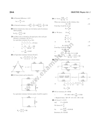
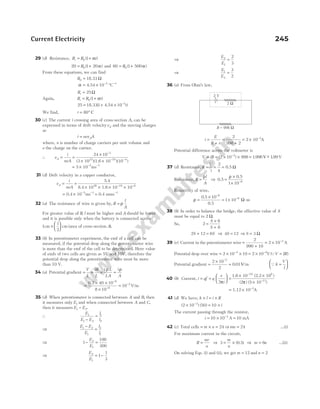
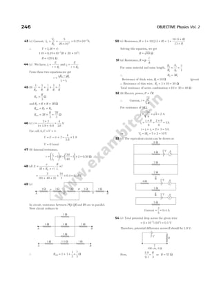
![55 (a) We have, r r
A B
= 2
∴ A A
A B
= 4
or l
l
A
B
=
4
∴ R R
B A
= 16
R R
R
A
B
net =
=
16
17 17
If Rnet = 4, then RA = 4.25Ω or RB = 68Ω.
56 (d) Balanced condition for Wheatstone’s bridge,
R
R
R
R
1
2
3
4
=
We have,
24
84
10
30
1
3
+
+
= =
X
Y
…(i)
and
3
1
24 84
10 30
=
+ + +
+
X Y
[QV IR
= ]
=
+ +
108
40
X Y
…(ii)
Solving Eqs. (i) and (ii), we get
X Y
= = 6Ω
57 (b) The given circuit can be redrawn as
It is a balanced Wheatstone bridge and hence, no current
flows in the middle resistor, so equivalent circuit would be as
shown in figure.
10 Ω and 20 Ω resistances are in series,
∴ R′ = + =
10 20 30
Ω Ω Ω
Similarly, 5Ω and 10 Ω are in series, R′ ′ = 15Ω
Now, R′ and R′ ′ are in parallel, R =
×
+
=
15 30
15 30
10 Ω
So, i
V
R
= = =
5
10
0 5
. A
58 (c) We know that, when current flow is same then resistors
are connected in series, hence resultant resistance is
R R R
′ = +
1 2 = +
10 20
Ω Ω = 30 Ω
Also since, cells are connected in opposite polarities, the
resultant emf is
E E E
= −
1 2 = −
5 V 2 V = 3 V
From Ohm’s law, E iR
= ⇒i
E
R
= = =
3
30
0.1 A
59 (b) Here, the resistances of 400 Ω and 10000 Ω are in
parallel, so their effective resistance RP will be
RP =
×
+
400 10000
400 10000
=
5000
13
Ω
Total resistance of the circuit,
R = + =
5000
13
800
15400
13
Ω
Current in the circuit, i = =
6
15400 13
39
7700
/
A
Potential difference across voltmeter,
V iRP
= = ×
39
7700
5000
13
= 195
. V
60 (b) Current, i
E
R r
=
+
. When R decreases to 0, i
E
r
= and
V IR
= = 0.
61 (c) Initially,
P
Q
=
−
=
−
l
l
100
20
100 20
= =
20
80
1
4
When a resistance of 15Ω is connected in series with the
smaller of the two, i.e. with P, then
P
Q
+
=
15 40
60
⇒
P
Q Q
+ =
15 2
3
1
4
15 2
3
+ =
Q
⇒
15 5
12
Q
=
⇒ Q = 36 Ω
Resistance, P = × =
1
4
36 9Ω
62 (d) Effective voltage on charging
= × −
4 1 4 2
. = 3 6
. V
Total resistance = 8Ω
⇒ i V R
= = =
/ /
3.6 0.45
8 A
63 (d) Since, on balancing no current flows through the battery
so its internal resistance will not affected.
Potential gradient =
E
100
So, balancing emf = ×
E
100
30 =
30
100
E
64 (c) When a resistance of 100 Ω is connected in series, then
the current flowing will be
i
V
R
=
+
100
…(i)
When a resistance of 1000 Ω is connected in series, the range
of galvanometer gets doubled.
Current, i
V
R
=
+
2
1100
…(ii)
Current Electricity 247
5 W 10 W
20 W
10 W
5 V
i
-
+
5 Ω 10 Ω
20 Ω
10 Ω
−
+
5 V
i
10 Ω](https://image.slidesharecdn.com/arihantneetobjectivephysicsvolume2bydcpandey2022edition-230417145135-9bce7664/85/Arihant_NEET_Objective_Physics_Volume_2_By_DC_Pandey_2022_Edition-pdf-258-320.jpg)
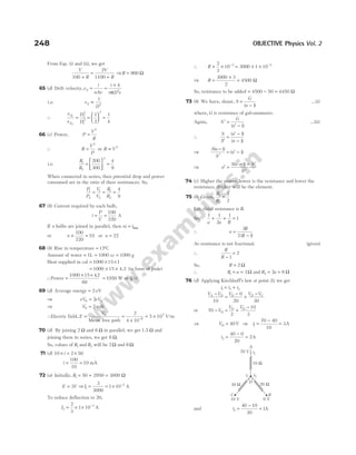
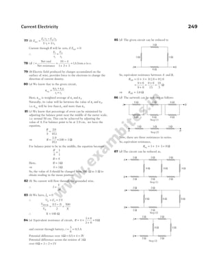
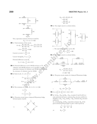
![98 (d) The circuit can be drawn as,
Resistance between points P and S = 4 Ω
99 (b) In the first case, potential difference balances against
resistance R V k l
, 1 1
= ⇒R kl
= 1Ω (QI = 1A)
In the second case, potential difference balances against R X
+ ,
V kl
2 2
= ⇒ R X kl
+ = 2
∴Potential difference balance over X = −
k l l
( )
2 1 Ω
100 (d) Power = 1.08 kW = 1080 W
P t E
× = ⇒ 1080 × = ×
t m L
1080 × = × ×
t 100 540 42
. ⇒ t = 210 s
101 (b) For an ammeter,
i
i
S
G S
g
=
+
⇒ i G i i S
g g
= −
( )
∴ i G i r
g g
= −
( . )
0 03 4 …(i)
and i G i r
g g
= −
( . )
0 06 …(ii)
From Eqs. (i) and (ii), we get
012 4 0 06
. .
− = −
i i
g g
Maximum current through the galvanometer, ig = 0.02 A
102 (c) When key K is opened, bulb B3 will not draw any current
from the source. So, that terminal voltage of source increases.
Hence, power consumed by bulb increases. So, light of the
bulb B2 becomes more. The brightness of bulb B1 decreases.
103 (a) Maximum current possible in galvanometer,
Imax = × × −
25 4 10 4
A = −
10 2
A
So, 10
100
2
−
=
+
2.5
R
100 250
+ =
R
Resistance, R = 150 Ω
104 (a) Let, the bulb 400 W is having resistance value of R. For
200 W, necessary value of resistance will be 2R.
Total value of resistance in the circuit will be R R R
+ = 2
If I is the maximum current in the circuit, then I R
2
400
= W
Power of circuit as a whole = × = × = ×
I R I R
2 2
2 2 2 400
= 800 W
105 (b) Maximum current possible in bulb = =
50
100
0 5
. A
Resistance of each bulb = =
×
=
V
P
2
100 100
50
200 Ω
If n be the number of bulbs possible, then total resistance of
circuit = +
200
10
n
Maximum current in the circuit = 0 5
. ×n
So,
120
200
10
n
+
= 0 5
. n ⇒ n = 4
106 (c) Let R x
AB = . Then,
R
x
x
AB = +
+
1
1
or x
x
x
= +
+
1
1
∴ x x x x
+ = + +
2
1 or x x
2
1 0
− − =
x =
+ +
1 1 4
2
=
+
1 5
2
Ω
107 (a) Potential difference across 4Ω resistance = + =
20 16 36V
Current through 4Ω resistance = =
36
4
9A [from top to bottom]
Similarly, current through 2Ω resistance =
−
=
20 16
2
2A
Therefore, total current through 20 V battery will be 11 A.
108 (b) Current through R1 and R2 comes out to be zero (potential
difference = 0).
∴ Current through R3 =
Net emf
Total resistance
=
+ + − + +
( ) ( )
4 3 2 2 3 2
3
=
2
3
A
109 (b) According to the question, R
i
= +
20
2
Ω
Now, current, i
R i
= =
+
250 250
20 2
( / )
⇒ i i
2
40 500 0
+ − =
Solving, we get
i = 10 A
110 (d) According to question,
Q at bt
= − 2
⇒ i
dQ
dt
a bt
= = − 2
i = 0 at t
a
b
=
2
di
dt
b
= − 2
111 (a) The given three resistors are in parallel,
Current Electricity 251
x
1Ω
1Ω
A
B
S
P
5 Ω 5 Ω
3 Ω 3 Ω
S
P
⇒
S
P
⇓
4 Ω
8 Ω 8 Ω
R
E
R
V
i
R
i/3](https://image.slidesharecdn.com/arihantneetobjectivephysicsvolume2bydcpandey2022edition-230417145135-9bce7664/85/Arihant_NEET_Objective_Physics_Volume_2_By_DC_Pandey_2022_Edition-pdf-262-320.jpg)
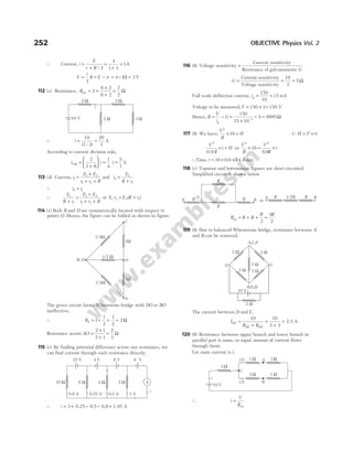
![Equivalent resistance of circuit,
Req = + =
3 2 5 Ω ⇒ i = =
10
5
2A
So, current in each branch = 1A
Now, V V
C A
− = × =
1 1 1V …(i)
and V V
C B
− = × =
1 3 3V …(ii)
Solving Eqs. (i) and (ii), we have
V V
A B
− = − =
3 1 2V
121 (d) When K1 is closed, R1 is short-circuited.
When K2 is open, I
E
r R
E
r
0
2 100
=
+
=
+
...(i)
When K2 is closed, I
E
r
0
1
2 50
=
+
...(ii)
From these two equations, we get r = 0
When K1 is open and K2 is closed,
I E
R
0
1
2 2 50
=
+
( )
...(iii)
From Eqs. (i) and (iii), we have
R1 50
= Ω
122 (b) In the circuit, we can see that 20 100
Ω Ω
, and 25 Ω are
in parallel.
Net resistance of circuit = + +
+ +
4 6
1
1
20
1
100
1
25
= 20 Ω
∴ V iR
= = × =
4 20 80 V
123 (c) Let current through XY is i3. Applying Kirchhoff’s law to
loops (1) and (2),
i i i
1 3 2
0 3 0
+ × − =
∴ i i
1 2
3
= …(i)
and − − + + =
2 4 0
1 3 2 3
( ) ( )
i i i i
So, 2 4 6
1 2 3
i i i
− = …(ii)
Also, 50 2
1 1 3
= + −
i i i
( )
∴ 3 2 50
1 3
i i
− = …(iii)
From Eqs. (i), (ii) and (iii), we get
i3 2
= A
124 (b) The simplified circuit can be drawn as,
Applying KVL in loop (1) and (2), we get
8 16
3
i =
⇒ i3 2
= A …(i)
and 4 16 8 8
1 3
( )
i i
− = − =
⇒ i i
1 3
2 4
= + = A [using Eq. (i)]
The current in a circuit is distributed depending on the value
of resistance as shown below.
∴ i2
1
2
= A
⇒
i
i
1
2
4
1 2
8
= =
( / )
(B) Medical entrance special format
questions
l Assertion and reason
1 (d) R1 and R2 are resistances per unit length.
V iR
1 1 1
=
and V i R
2 2 2
=
R R
2 1
> as R
A
∝
1
As, i i
1 2
=
Hence, V V
2 1
>
3 (b) The resistance of milliammeter becomes high because of
increased number of turns of coil, so the torque produced in
the coil is not decreased due to low value of current.
Milliammeter generally do not have shunt because the main
current is already very low. Even if there is shunt, its value is
kept high so that current diversion through it is least in case
of milliammeter.
4 (d) In both cases potential difference across R is E.
∴ P
E
R
=
2
i.e., power remains same.
In second case, net resistance will decrease. Therefore, main
current will increase.
Current Electricity 253
i3 ( )
i i
1 3
–
i1
1
2
8 V
16 V
8 Ω 4 Ω
8 W 8 W
16 V
8 W 1 W
3 W
4 W
2 W
2 W
8 V
1
—
2
A 1
—
2
A
1A
1A 2A 2A
4A
1
2
1 W 2 W
i1 ( )
i i
1 3
–
X
i3
i2 Y
( )
i i
2 3
+
4 W
1 2
3 W
50 V
i](https://image.slidesharecdn.com/arihantneetobjectivephysicsvolume2bydcpandey2022edition-230417145135-9bce7664/85/Arihant_NEET_Objective_Physics_Volume_2_By_DC_Pandey_2022_Edition-pdf-264-320.jpg)
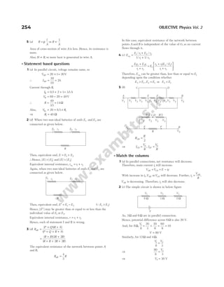
![(C) Medical entrances’ gallery
1 (a) Given, drift velocity,vd = × −
7 5 10 4
. m/s
Electric field, E = × −
3 10 10
Vm−1
Mobility, µ = ?
As, µ =
v
E
d
=
×
×
−
−
7 5 10
3 10
4
10
.
= × − −
2.5 10 m V s
6 2 1 1
2 (c) According to the carbon colour code for resistors,
Code of yellow = 4
Code of violet = 7
Code of brown, i.e. multiplier = 101
Code of gold, i.e. tolerance = ± 5%
Hence, resistance of resistor = × Ω
47 101
, 5%
= Ω
470 , 5%
3 (a) According to the question, the metre bridge is shown
below,
Given,
x
x
1
2
3
2
=
At balance condition in metre bridge,
R x
x
10
1
2
=
⇒ R
x
x
= ×
1
2
10 = ×
3
2
10 = 15 Ω
Now, length of given wire of resistance 15 Ω is 1.5 m.
Therefore, length of 1Ω resistance wire is
= =
1 5
15
1
10
.
= 0.1 or 1 10 1
× −
m
4 (b) Resistivity of copper (a metal) as a function of temperature
increases with the increase in temperature as shown below,
For copper at 0K, value of resistivity is 1.7 × −
10 8
Ω-m.
Hence, correct option is (b).
5 (b) Applying KVL in the loop, we get
4 1 4 1 2 0
I I I
+ ⋅ − + ⋅ − =
⇒ 6 6
I = ⇒ I = 1A
6 (b) Given, R R
1 2
= , l l
1 2
=
Since, resistance, R
l
A
= ⋅
ρ ⇒
R
R
l
l
A
A
1
2
1
2
2
1
= ⋅
⇒
R
R
l
l
A
A
1
1
1
1
2
1
= ⋅
⇒ 1 2
1
=
A
A
or
A
A
1
2
1
=
7 (b) Applying KVL rule in loop BCDEB,
R i E E i R
2 2 2 3 3 1 0
+ − − =
8 (b) Equivalent resistance between points A and B is
RAB = + + +
[( ) || ]
4 8 6 4 8 = +
[ || ]
12 6 12
=
×
+
+
12 6
12 6
12 = +
[ ]
4 12 = 16 Ω
9 (a) Case I When all bulbs are glowing, then the circuit can be
realised as shown in the figure below.
∴The equivalent resistance of this circuit is
R R R
A B
eq = +
As, section A has three parallel resistance, so equivalent
resistance,
R
R
A =
3
Similarly, for section B, equivalent resistance, R
R
B =
3
∴ R
R R R
eq = + =
3 3
2
3
… (i)
Thus, power consumed in this circuit,
P
V
R
E
R
E
R
1
2 2 2
3
2
= = =
eq
[using Eq. (i)] …(ii)
Case II When two from section A and one from section B
glow, the circuit can be realised as shown in the figure below.
Current Electricity 255
ρ
O T(K)
G
100 cm
R 10 Ω
x2
x1
E
R R
A B
R R
R R
E
A B
R
R
R](https://image.slidesharecdn.com/arihantneetobjectivephysicsvolume2bydcpandey2022edition-230417145135-9bce7664/85/Arihant_NEET_Objective_Physics_Volume_2_By_DC_Pandey_2022_Edition-pdf-266-320.jpg)
![∴ Equivalent resistance of section A,
R
R
A =
2
and of section B,
R R
B =
Thus, equivalent resistance of the entire circuit becomes
R R R
R
R
R
A B
eq = + = + =
2
3
2
… (iii)
∴Power consumed by this circuit,
P
V
R
E
R
E
R
2
2 2 2
2
3
= = =
eq
[using Eq. (iii)]… (iv)
So, ratio of power in two cases is obtained from Eqs. (ii)
and (iv),
P
P
E
R
R
E
1
2
2
2
3
2
3
2
9
4
= × = or 9 4
:
10 (c) Among given devices fuse is used in electric circuit as a
protection device.
It helps in preventing excessive amount of current to flow in
the circuit or from short circuiting.
It has low melting point and low resistivity, so when excess
amount of current flows in the circuit, then due to excessive
amount of heat, it melts and breaks the circuit.
11 (b) For an ideal voltmeter, the resistance is infinite and for an
ideal ammeter, the resistance is zero.
So, the current in circuit 1 is
R i V
× = or 10 10
1
i = ⇒ i1
10
10
1
= = A
∴ V i R
1 1 1 10 10
= × = × = V
Similarly, for circuit 2, the addition of 10 Ω to voltmeter does
not affect the current and hence
10 10
2
i = ⇒ i2
10
10
1
= = A
V i R
2 2 1 10 10
= = × = V
∴ V V
1 2
= and i i
1 2
=
12 (d) The balance condition still remains the same, if the jockey
points the same point P given in the initial condition, for
which there is no deflection in the galvanometer or no
current will be drawn from the cell. Thus, the bridge will
work as usual and balance condition is same, P Q l l
/ /
= 1 2.
13 (d) The given circuit diagram can be drawn as shown below
The equivalent resistance of circuit is given by
1 1 1
R R R
AE DF
eq
= +
=
+
+
+
1
20 30
1
30 20
( ) ( )
= + =
1
50
1
50
2
50
⇒ Req = Ω
25
The current in circuit, I
V
R
= =
2
25
A
As the resistance of two branches is same, i.e. 50 Ω.
So, the current I I
1 2
=
⇒ I I I
= +
1 2
⇒
2
25
21
= I
⇒ I I
2 1
1
25
= = A
∴The voltage across AB,
V IR
1 1 1
1
25
20
= = × V
and voltage across CD,
V I R
2 2 2
1
25
30
= = × V
∴Voltmeter reading
= −
V V
2 1 = −
30
25
20
25
= =
10
25
0 4
. V
14 (a) Given, for a wire,
R
l
=
1
2
Length of wire, l = 5 cm = × −
5 10 2
m
∴ R
l
=
2
= × −
2 5 10 2
. Ω
Potential difference,V = 1V or IR = 1
I
R
=
1
=
× −
1
2 5 10 2
.
=
100
2 5
.
= 40 A
15 (c) Given, current, I = 10 A
Area of cross-section, A = × −
4 10 6
m2
Density of conductors, ρ = 2 7
. g/cc = ×
2 7 103
. kg/m3
Molecular weight of aluminium, Mw = 27g = × −
27 10 3
kg
If n be the total number of electrons in the conductor per unit
volume, then
256 OBJECTIVE Physics Vol. 2
10 V
V1 A1
i1
10 Ω
Circuit 1
10 V
V2
i2
10 Ω
10 Ω
Circuit 2
A2
V
20 Ω 30Ω
30 Ω 20 Ω
I1
I2
A
D
I
F
E
C
B
2V](https://image.slidesharecdn.com/arihantneetobjectivephysicsvolume2bydcpandey2022edition-230417145135-9bce7664/85/Arihant_NEET_Objective_Physics_Volume_2_By_DC_Pandey_2022_Edition-pdf-267-320.jpg)
![60 (c) The combination of resistors can be redrawn as
Therefore, equivalent resistance is given by
1 1 1 1
R R R R
eq
= + + ⇒ R
R
eq =
3
61 (c) From the circuit (potentiometer),
V E
CB = (if no current is drawn from the battery)
⇒
E
R R
R E
AB
CB
1
+
= …(i)
Given, E1 2
= V and RAB = 10 Ω
∴ RCB = × =
40
100
10 4 Ω and E = × −
10 10 3
V
On solving Eq. (i), we get R = 790 Ω
62 (d) We know that, potential drop across a resistance,
V I R
= ⇒ V = constant
i.e. I
R
∝
1
I I I
R R R
1 2 3
1 2 3
1 1 1 1
2
1
3
1
4
6 4 3
: : : : : : : :
= = =
63 (a) Total internal resistance does not change
∴ ′ =
R r
4
Net emf, ′ = −
E E n m
( )
2
Here, n = total number of cells = 4
m = wrong connection = 1
′ = −
E E[ ]
4 2 , i.e. ′ =
E E
2
64 (a) Given, I = 3 A andV = 6V
We know that,V IR
=
R
V
I
= ⇒ R = =
6
3
2 Ω
If the ammeter and voltmeter have resistance, then R < 2Ω.
65 (b) Given, R1 100
= Ω
R2 200
= Ω ⇒ T1 100
= ° C
α = 0 005
. per °C
We know that, new resistance of the bulb filament,
R R T T
2 1 2 1
1
= + −
[ ( )]
α
200 100 1 0 005 100
2
= + −
[ . ( )]
T
2 1 0 005 100
2
= + −
[ . ( )]
T
0 005 100 1
2
. ( )
T − =
T2 100
1
0 005
− =
.
⇒ T2 100
1000
5
− =
T2 100 200
− =
⇒ T2 200 100 300
= + = ° C
66 (d) Consider the ring as two parts. As two resistances are
joined in parallel between two points A and B, then two
resistances would be
R
R
r
r
R
1
2 2
= ⋅ =
π
θ
π
θ
and R
R
r
r
R
2
2
2
2
2
= − = −
π
π θ
π
π θ
( ) ( )
Now, equivalent or effective resistance between A and B,
R
R R
R R
eq =
×
+
1 2
1 2
⇒ R
R R
R
R
R
eq =
× −
+ −
=
−
2 2
2
2
2
2
4
2
2
2
2
π
θ
π
π θ
π
θ π θ
θ π θ
π
π
π
( )
[ ]
( )
=
−
× =
−
R
R
R
2
2 2
2
4
2
2
2
4
θ π θ
π
π
π
θ π θ
π
( ) ( )
67 (b) Case I For balanced point of meter bridge,
5
100
1
1
R
l
l
=
−
…(i)
Case II When R is shunted with equal resistance, i.e. R
1 1 1
′
= +
R R R
⇒ ′ =
R R/2
∴
5
2 100
1
1
R
l
l
/
=
−
1.6
1.6
…(ii)
From Eqs. (i) and (ii), we get
2
100 100
1
1
1
1
l
l
l
l
−
=
−
1.6
1.6
⇒ l1 25
= cm
From Eq. (i),
5 25
75
R
= ⇒ R = 15 Ω
68 (c) As, r = internal resistance,
and r R
l l
l
=
−
1
1
1
⇒
rl
R
l l
1
1
1
= − …(i)
Also, r R
l l
l
=
−
2
2
2
⇒
rl
R
l l
2
2
2
= − …(ii)
Subtracting Eq. (i) from Eq. (ii), we get
l l r
l
R
l
R
1 2
2
2
1
1
− = −
At, R1 = ∞, l1 3
= m and at, R2 = 9.5 Ω, l2 5
= 2.8 m
⇒ ( )
.
3 5
5
95
0
− = −
2.8
2.8
r
⇒ r = 0 5
. Ω
Current Electricity 263
G
C
R
i E
B
E1
A
a
b
R R R](https://image.slidesharecdn.com/arihantneetobjectivephysicsvolume2bydcpandey2022edition-230417145135-9bce7664/85/Arihant_NEET_Objective_Physics_Volume_2_By_DC_Pandey_2022_Edition-pdf-274-320.jpg)
![69 (a) As, current I I
G =
2
1000
Also, I
G
G r
I
r =
+
We know that, potential across G and shunt r are same.
∴ V V
G r
= ⇒ I G I r
G r
( ) =
⇒
2
1000
IG GI
G r
r
=
+
( ) ⇒ 2 1000
( )
G r r
+ =
⇒ G r r
+ = 500 ⇒
G
r
+ =
1 500
⇒ G r
/ = 499 ⇒ r G
=
1
499
70 (c) Corresponding to the colours of the first and second bands,
i.e. green and black, the figures are 5 and 0.
Corresponding to the colour of third band, i.e. violet, the
multiplier is 107
. Therefore, the value of the resistance is
50 107
× Ω. The gold colour of the fourth band indicates the
tolerance of ±5%.
So, the value of the resistor is written as
50 10
× ± = × ± ±
7
Ω Ω % = % Ω
5% 500 10 5 500 5 M
6
71 (c) The required resistance =
×
+
= =
R R
R R
R
2 2
2 2
4
9
4
Ω
72 (c) Let the values of resistances be R1 and R2, respectively.
When R1 and R2 resistances are in series, then
R R
1 2 6
+ = (according to question) …(i)
When R1 and R2 resistances are parallel, then
R R
R R
1 2
1 2
4
3
+
= …(ii)
From Eq. (i), we get
R R
1 2
6
4
3
= ⇒ R R
1 2 4 2
= × ⇒ R R
1 2 8
= …(iii)
We know that,
R R R R RR
1 2 1 2
2
1 2
4
− = + −
( ) = − ×
36 4 8
⇒ R R
1 2 4
− =
⇒ R R
1 2 2
− = …(iv)
From Eqs. (i) and (iv), we get
R R
1 2
4 2
= =
Ω Ω
,
73 (d) Given, 6 6
Ω Ω
, and 6Ω are in parallel.
So,
1 1
6
1
6
1
6
3
6
R
= + + =
∴ R = =
6
3
2 Ω
Now, 6Ω and 6Ω are in series.
So, ′ = + =
R 6 6 12Ω
∴
1 1 1
12
′′
=
′
+
R R
= + =
1
12
1
12
2
12
⇒ ′′ =
R 6 Ω
The required resistance of the circuit = + =
2 6 8 Ω.
So, the potential difference,
V V iR
A B
− = = × =
0 5 8 4
. V
74 (a) Total emf of the cell = − =
3 2
E E E
Total internal resistance = 4r
∴Total resistance of the circuit = +
4r R
So, the current in the external circuit
i
E
r R
=
+
2
4
Qi
V
R
=
75 (b) As, resistances 1 2
Ω Ω
, and 1Ω are in parallel.
So, the required internal resistance,
1 1 1 1 1
1
1
2
1
1
2 1 2
2
1 2 3
r r r r
= + + = + + =
+ +
⇒ r =
2
5
Ω
The potential difference between points P and Q,
E
E
r
E
r
E
r
r
=
+ +
=
+ +
1
1
2
2
3
3
1
1
1
2
2
3
1
5 2
/ /
=
+ +
= = × =
2 2 6
2
5 2
10 2
5 2
10
5
2
2
2
/
/
/
V
76 (d) Given, R R E r I
1 2
2 6 2 0 5
= = = = =
Ω, Ω Ω
, . , ?
V,
Q R R
1 2
, are in parallel combination.
So,
1 1 1 1
2
1
6
1 2
R R R
= + = + =
+
3 1
6
⇒ R = =
6
4
1.5 Ω
Then, the current in the circuit,
I
E
r R
=
+
=
+
= =
2
0 5
2
20
1
. .
1.5
A
(as internal resistance, r is in series with other resistance)
77 (b) As, mobility =
drift velocity
electric field
⇒µ = = =
v
E
d metre
volt-second joule/coulomb -second
2 2
[ ]
( )
L
= −
[ ]
[ ]
L 2
2 2
kg-metre -second -second
ampere-second
= =
− −
−
[ ]
[ ]
[ ]
L
ML T A
M T A
2
2 2 1
1 2
264 OBJECTIVE Physics Vol. 2
E E E E
E1 = 1V
P Q
E2 = 2V
E3 = 3V
G
Ir
I IG
Resistance of
galvanometer
r](https://image.slidesharecdn.com/arihantneetobjectivephysicsvolume2bydcpandey2022edition-230417145135-9bce7664/85/Arihant_NEET_Objective_Physics_Volume_2_By_DC_Pandey_2022_Edition-pdf-275-320.jpg)
![Q
m
m
it
i t
1
2
11
2 2
= ⇒
m
m2
4 120
6 40
=
×
×
⇒ m
m m
2
6 40
4 120 2
=
× ×
×
=
88 (d) As R l
∝ 2
. When wire is stretched,
∴ ′ = = × = × =
R n R
2 2
2 4 4 4 16 Ω
89 (b) As I
E
R r
=
+
or E I R r
= +
( )
⇒ 21 0 2 10
. . ( )
= + r
10
21
2
10
+ = ×
r
.
∴ r = − =
10 5 10 0 5
. . Ω
90 (b) Effective resistance,
Reff =
×
+
= =
40 120
120 40
4800
160
30 Ω
∴ Current, I =
+
= =
7
30 5
7
35
0 2
( )
. A QI
E
R r
=
+
91 (b) Current, I qf
=
Given, q = × −
1 6 10 19
. C and f = 1019
∴ I = 1.6 A
92 (c) v
I
nAe
d =
Given, I n
= = × −
2 586 1028 3
A m
, .
A r e
= = × = ×
− −
π π
2 2 2 19
01 10 1 6 10
( . ) , . C
∴ Drift velocity, vd = × − −
0 68 10 4 1
. ms
93 (a) As, R l d
∝ / 2
⇒R R
l d
l d
2 1
2 1
2
1 2
2
=
= × =
1.5(0.31)
(0.155)
4.2 25.2
2
2
Ω
94 (d) Suppose, m rows are connected in parallel and each row
contains n identical cells (each cell havingE = 1.5V andr = 1Ω)
For maximum current in the external resistance R, the
necessary condition
R
nr
m
=
1.5 =
×
n
m
1
1.5m n
= …(i)
Total cells = = ×
24 n m …(ii)
On solving Eqs. (i) and (ii), we get
m = 4
n = 6
Therefore, 6 cells in each row are connected in series and
4 such rows are connected in parallel.
95 (d) R R t
1 0 1
= +
( )
α
1 1 0 00125 27
0
= + ×
R ( . ) …(i)
2 1 0 00125
0
= + ×
R t
( . ) …(ii)
From Eqs. (i) and (ii), we get
t = ° =
854 1127
C K
96 (d) We know that,
i
E
r R
=
+
=
+
eff
15
0 5 145
. .
= =
15
1
15
A
97 (b) Given, temperature coefficient of carbon,
α1
3
4 10
= × °
−
/ C
Temperature coefficient of copper,
α2
3
10
= − × °
−
0.5 / C
Hence, R R
1 1 2 2
α α
= −
R
R
2
1
=
− ×
×
−
−
4 10
0.5 10
3
3
⇒
R
R
2
1
8
1
=
98 (*) Let the three conductors having resistances R R
1 2
, and R3
respectively, and the current drawn by them are 1 2
A A
, and
3 A respectively, when connected in turn across a battery.
∴ V R V R
= =
1 2
2 andV R
= 3 3
So, R V R
V
1 2
2
= =
, and R
V
3
3
=
When the conductors are connected in series, across the same
battery, then
V I R R R
= + +
[ ]
1 2 3
⇒ V I V
V V
= + +
2 3
⇒ 1
6 3 2
6
=
+ +
I or I =
6
11
A
99 (d) R l m
∝ 2
/ ⇒R R R
l
m
l
m
l
m
1 2 3
1
2
1
2
2
2
3
2
3
: : : :
=
= =
25
1
9
3
1
5
125 15 1
: : : :
100 (b) We have, I
I R
R
I
1
2
3
2
3
=
×
=
∴ H I R
I
R
1 1
2
2
4
9
= = × …(i)
Also, I
I R
R
I
2
3 3
=
×
=
∴ H I R
I
R
2 2
2
2
2
9
2
= = ×
( ) …(ii)
and H I R
3
2
= ( )
1.5 …(iii)
From Eqs. (i), (ii) and (iii), we get
H H H
I
R
I
R I R
1 2 3
2 2
2
4
9 9
2
: : : :
= × × × 1.5
= =
4
9
2
9
: : 1.5 4 : 2 : 13.5
= 8 4 27
: :
101 (a) A milliammeter will have greater resistance than ammeter
because (1) number of turns in the coil in milliammeter is
increased to compensate low value of current to create large
deflection. (2) milliammeter does not have usually a shunt in
parallel because main current is very small. Ammeter usually
have a shunt in parallel which makes overall resistance low.
266 OBJECTIVE Physics Vol. 2](https://image.slidesharecdn.com/arihantneetobjectivephysicsvolume2bydcpandey2022edition-230417145135-9bce7664/85/Arihant_NEET_Objective_Physics_Volume_2_By_DC_Pandey_2022_Edition-pdf-277-320.jpg)
![102 (c) We know that, the resistance of any wire,
R
L
A
=
ρ
In given case, L L
1 = , L L
2 2
= , ρ and A are constants.
Hence,
R
R
L
L
1
2
1
2
= ⇒
R
R
L
L
1
2 2
= ⇒
R
R
1
2
1
2
=
103 (c) Power when connected in series,
1 1 1
1 2
P P P
= +
Given, P1 60
= W and P2 100
= W
Hence, P =
×
+
60 100
60 100
⇒ P =
6000
160
⇒ P = 375
. W
104 (b) We know that, drift velocity, v
e E
m
e
m
V
l
d = =
τ τ
Here, v v
d ∝
Given, condition V V
1 = and V V
2 2
=
Hence,
v
v
V
V
d
d
′
=
2
⇒ v v v
d d
′ = =
2 2
105 (c) Using,V IR
=
100 10 10
3
× = ×
−
I
⇒ I = 0 01
. A
Also, I
E
R R
=
+ ′
⇒
2
10
0 01
+ ′
=
R
. ⇒ R′ = 190 Ω
106 (d) Specific resistance of a material is the characteristic
property, it does not depends upon the dimensions of
material, hence it does not depend upon length.
107 (b) 7 Ω and 3 Ω are in series, so total 10 Ω and 10 Ω are in
parallel, so total resistance across AC = 5Ω. Now, 5 Ω and 5
Ω are in series, so they make 10 Ω. Now, 10 Ω and 10 Ω are
in parallel, so Rnet = 5Ω.
108 (a) Equivalent resistance in series = + =
6 9 15Ω
Current flow in circuit, i
V
R
= = =
120
15
8 A
Voltage in 6 Ω resistor,V iR
= = × =
8 6 48 V
Power consumed by 6 Ω resistor,
P
V
R
= =
×
2
48 48
6
= ×
8 48 = 384 W
109 (a) Current through each arm DAC and DBC = 1A
V V
D A
− = 2 and V V
D B
− = 3
∴ V V
A B
− = 1V
110 (b) Heat = i Rt
2
∴
E
R r
R
E
R r
R
1
2
1
2
2
2
+
=
+
[Qt is the same]
On solving, we get
( ) ( )
R R r R R RR
1 2
2
1 2 1 2
− = −
⇒ r R R
= 1 2
111 (b) Applying Kirchhoff’s law, 500 100 12
I I
+ =
So, I =
×
= ×
−
−
12 10
6
2 10
2
2
A
Hence, VB = × =
−
100 2 10 2
2
( ) V
112 (a) The full scale deflection current,
i
G
g =
25 mV
ampere
where, G is the resistance of the meter.
The value of shunt required for converting it into ammeter of
range 25 A is S
i G
i i
g
g
=
−
.
⇒ S = =
25 mV
25
0.001 Ω
113 (c) Power, P
V
R
=
2
For small variation,
∆ ∆
P
P
V
V
× =
×
×
100
2
100
% %
= × =
2 25 5
. %
Therefore, power would decrease by 5%.
114 (a)
Resistance, R =
×
+
=
×
=
6 12
6 12
6 12
18
4 Ω
Total resistance, Req = + =
6 4 10 Ω
Current, i
V
R
= = =
10
10
1A
The current in 12 Ω resistor is
i i
R
R R
2
1
1 2
1
6
6 12
=
+
= ×
+
⇒i2
1
3
= A
The potential difference in 12 Ω resistor,
V i
= × 12 = × =
1
3
12 4V
115 (b) Given, A = 0.3 m2
, n = ×
2 10 /m
25 3
q t t
= + +
3 5 2
2
i
dq
dt
t
= = + =
6 5 17 A (at t = 2 s)
We have current, i ne Avd
=
Drift velocity,v
i
ne A
d = =
× × × ×
−
17
2 10 1.6 10 0.3
25 19
=
× −
17
0 96 10 6
.
= × −
1.77 10 5
ms−1
Current Electricity 267
6 Ω
6 Ω
12 Ω
i1
i2
10 V](https://image.slidesharecdn.com/arihantneetobjectivephysicsvolume2bydcpandey2022edition-230417145135-9bce7664/85/Arihant_NEET_Objective_Physics_Volume_2_By_DC_Pandey_2022_Edition-pdf-278-320.jpg)
![R
r r
r
r r
r r
r
CA = +
=
×
+
=
3 2
3
3
2
3
3
2
3
11
||
R R R
AB BC CA
: : : :
= 5 4 3
130 (a) Given circuit is a balanced Wheatstone bridge. So, diagonal
resistance of 2 Ω will be ineffective.
Equivalent resistance of upper arm = + =
2 2 4Ω
Equivalent resistance of lower arm = + =
2 2 4 Ω
∴ RAB =
×
+
=
4 4
4 4
2Ω
131 (b) In open circuit, current through the circuit i = 0
Potential difference between x and y will be
V E
= = 120 V
132 (d)
1 1
10
1
10
1
20
R′
= + +
⇒ R′ = =
20
5
4Ω
Now, using Ohm’s law, i
R R
=
+ ′
25
⇒ 0 5
25
4
. =
+
R
⇒ R + =
4
25
0 5
.
⇒ R = − =
50 4 46Ω
Current through 20 Ω resistor =
×
+
= =
0 5 5
20 5
2 5
25
01
. .
. A
Potential difference across middle resistor
= Potential difference across 20 Ω = × =
20 01 2
. V
133 (b) The given circuit can be shown as the resistance between
A and B =
2
3
Ω.
Total resistance of the circuit
R = + =
2
2
3
8
3
Ω
So, the reading of ammeter,
i
V
R
= = = =
2
8 3
6
8
3
4
/
A
134 (d) The resistances of branches ABC and ADC are in parallel.
The current entering at node A will equally divided in each
parallel branch.
∴ V V IR
A B
− = = × =
1 2 2 V
Point A is at greater potential with respect to point B, so
V V
A B
− = + 2 V
135 (b) Equivalent potential in the given parallel circuit is given as
E
E
r
E
r
r r
eq =
+
+
1
1
2
2
1 2
1 1
=
+
+
E r E r
r r
1 2 2 1
1 2
Here, E1 2
= V, E2 1
= V, r1 1
= Ω
and r2 2
= Ω
⇒ Eeq =
× + ×
+
2 2 1 1
2 1
=
+
=
4 1
3
5
3
V
136 (c) Here are two batteries with emf E each and the internal
resistances r1 and r2, respectively.
Hence, we have I R r r E
( )
+ + =
1 2 2
Thus, I
E
R r r
=
+ +
2
1 2
… (i)
Now, the potential difference across the first cell would be
equal toV E Ir
= − 1. From the question,V = 0, hence
E Ir
Er
R r r
= =
+ +
1
1
1 2
2
[from Eq. (i)]
⇒ R r r r
+ + =
1 2 1
2
Hence, R r r
= −
1 2
137 (b) The net resistance,
R =
×
+
+ = +
12 4
12 4
2
48
16
2 = 5 Ω
Electric current,
i
E
R r
=
+
=
+
=
12
5 1
2A
From current division rule,
i2
12
12 4
2
=
+
×
= × =
3
4
2 1.5 A
and i1 2
= − =
1.5 0.5 A
Current Electricity 269
A
2 Ω
2 Ω
2 Ω
2 Ω
2 V
A B
E E
r1 r2
R
I
25 V
0.5 A
R
R¢](https://image.slidesharecdn.com/arihantneetobjectivephysicsvolume2bydcpandey2022edition-230417145135-9bce7664/85/Arihant_NEET_Objective_Physics_Volume_2_By_DC_Pandey_2022_Edition-pdf-280-320.jpg)

![Thus, from the above figures, he concluded that a
magnetic field is established around a current carrying
wire due to which such deflections are visible.
Oersted’s experiment shows the connectivity between the
magnetic field and electric current and as electric current
means moving charges, he also concluded that moving
charges also produce magnetic field in their surroundings.
Biot-Savart’s law (Magnetic field due
to a current carrying conductor)
Biot-Savart’s law is an experimental law predicted by Biot
and Savart. This law deals with the magnetic field
produced at a point due to a small current element (a part
of any conductor carrying current).
Consider a wire XY carrying current I. Let dl be the
infinitesimal element of the conductor, dB be the magnetic
field at point P at a distance r from the element.
Biot-Savart’s law states that, the magnitude of the
magnetic field induction dB at the point P due to the
current element is
● directly proportional to the current flowing through the
conductor, i.e. dB I
∝ …(i)
● directly proportional to the length of the element,
i.e. dB dl
∝ …(ii)
● directly proportional to the sine of angle between the
length of element and line joining the element to the
point, i.e. dB ∝ sin θ …(iii)
● inversely proportional to the square of distance between
the element and the point, i.e. dB r
∝1 2
/ …(iv)
Combining all the above four relations, we get
dB
Idl
r
∝
sinθ
2
This relation is called Biot-Savart’s law.
If conductor is placed in air or vacuum, then magnitude of
magnetic field is given by
| |
dB =
µ
π
0
4
Idl
r
sinθ
2
where,
µ
π
0
4
is the proportionality constant.
µ0 is called the permeability of free space (or vacuum).
In SI unit, µ π
0
7
4 10
= × −
Tm/A or Wb/A-m and its
dimensions are [ ]
MLT A
− −
2 2
. The value of
µ
π
0
4
in CGS
system is unity.
In vector form, Biot-Savart’s law can be written as
d
Id
B
l
∝
× r
r
| |3
= ⋅
×
µ
π
0
3
4
Id
r
l r
The direction of dB is represented by the right hand screw
rule or right hand thumb rule.
Similarly, magnetic field induction at point P due to
current through entire wire is
B
l r
= ⋅
×
∫
µ
π
0
3
4
Id
r
or B = ⋅
∫
µ
π
θ
0
2
4
Idl
r
sin
Biot-Savart’s law in a medium
If the conductor is placed in a medium, then vector form
of Biot-Savart’s law is given as
d
Id I d
r
r
B
l r
r
l r
=
×
=
×
µ
π
µ µ
π
4 4
3
0
3
| |
where, µr = relative permeability = =
µ
µ0
1
(for air or vacuum)
and µ = absolute permeability of the medium.
Biot-Savart’s law in terms of current density J
d
r
dV
B
J r
= ⋅
×
µ
π
0
3
4
( )
Q J
dl
dl
dl
= = =
I
A
I
A
I
dV
Magnetic Effect of Current and Moving Charges 271
Current
element
dB
P
X
I
I dl
Y
r
θ
Fig. 4.2 A long current carrying conductor
Battery
Key
(open)
Conducting
wire
+ –
A B
+ –
A B
+
–
A B
S N
S
N S
N
Magnetic compass
with no deflection
(a) (b) (c)
Key
(closed)
Key
(closed)
Compass showing
deflection in
one direction
Compass showing
deflection in
opposite direction
Fig. 4.1 Oersted’s experiment](https://image.slidesharecdn.com/arihantneetobjectivephysicsvolume2bydcpandey2022edition-230417145135-9bce7664/85/Arihant_NEET_Objective_Physics_Volume_2_By_DC_Pandey_2022_Edition-pdf-282-320.jpg)
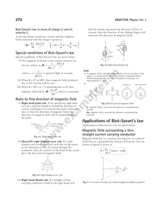
![Notedownthefollowing pointsregardingtheaboveequation
(i) For an infinitely long straight wire, α β
= = °
90
∴ B
i
d
i
d
= ° + ° = +
µ
π
µ
π
0 0
4
90 90
4
1 1
(sin sin ) ( ) =
µ
π
0
2
i
d
(ii) When wire is semi-infinite (at the foot of long wire),
α
π
=
2
and β = °
0
∴ B
i
d
= ° +
µ
π
π
0
4
0
2
sin sin ⇒ B
i
d
=
µ
π
0
4
(iii) For axial position of wire, i.e. when point P lies on
axial position of current carrying conductor, then
magnetic field at P,
B = 0 [since, θ = °
0 ]
(iv) B d
∝1/ , i.e. B-d graph for an infinitely long straight
wire is a rectangular hyperbola as shown in figure.
Magnetic field for different configurations
of the straight conductors
Magnitude and direction of magnetic fields associated with
different configurations of the straight conductors are given below
(i)
B
i
a
P =
µ
π
α
0
4
[sin ]q
(ii)
B
i
a
P = −
µ
π
α β
0
4
[sin sin ]q
(iii)
B
i
a
P =
µ
π
0
2
q
(iv)
B
i
a
P =
µ
π
0
4
q
(v)
B
i
a
P = +
µ
π
α
0
4
[sin 1] q
(vi)
B
i a b
ab
O =
+
8
4
0
2 2
µ
π
q
When a b B
i
a
O
= =
,
8 2
4
0
µ
π
Example 4.1 A current of 10 A is flowing east to west in a
long wire kept in the east-west direction. Find magnetic field
in a horizontal plane at a distance of (i) 10 cm north, (ii)
20 cm south from the wire and in a vertical plane at a
distance of (iii) 40 cm downwards (iv) 50 cm upwards.
Sol. The magnitude of the magnetic field at a distance r from a
long wire carrying a current i is given by
B
i
r
=
µ
π
0
2
where,
µ
π
0 7 1
2
2 10
= × − −
T mA .
(i) The magnetic field in a horizontal plane at a distance of
10 cm ( 0.10 m)
= north from the wire,
BN = × −
( )
2 10 7 10
0.10
= × −
2 10 5
T
The current in the wire is from east to west. So,
according to the right hand palm rule, the direction of
the field at the point towards north will be downwards
in a vertical plane.
(ii) The magnetic field at a distance of 20 cm ( . )
= 020 m
south from the wire, BS = × = ×
− −
( )
2 10
10
0
1 10
7 5
0.2
T
The direction of the field will be upward in the vertical
plane.
(iii) The magnetic field at a distance of 40 cm ( . )
= 0 40 m
from the wire downwards in the vertical plane,
BD = × = ×
− −
( )
.
2 10
10
0 40
5 10
7 6
T
The field will be in a horizontal plane pointing south.
(iv) The magnetic field at a distance of 50 cm ( . )
= 0 50 m
above the wire in the vertical plane,
BU = × = ×
− −
( )
2 10
10
4 10
7 6
0.50
T
The field will be in a horizontal plane pointing north.
Example 4.2
(i) A pair of stationary and infinitely long bent wires are placed
in the XY-plane as shown in figure. The wires carry currents
10 A each. The segments P and Q are parallel to the Y-axis
such as OS OR
= = 0.02 m. Find the magnitude and direction
of the magnetic field at the origin O.
(ii) Three long wires carrying currents 10 A, 20 A and 30 A are
placed parallel to each other as shown below. Points P and Q
are in the midway of wires. Find ratio of magnetic fields at
points P and Q.
Magnetic Effect of Current and Moving Charges 273
B
d
Fig. 4.8 B-d graph for an infinitely long straight wire
α
i
a
P β
α
i
P
a
P
a
i
to ∞
to ∞ P
a
i
to ∞
Starting point
to ∞
α
i
P
Starting point
a
a
b
O i
i R
P
O S
Q
i
X
Y
30A 20A 10A
2d 2d
Q P](https://image.slidesharecdn.com/arihantneetobjectivephysicsvolume2bydcpandey2022edition-230417145135-9bce7664/85/Arihant_NEET_Objective_Physics_Volume_2_By_DC_Pandey_2022_Edition-pdf-284-320.jpg)
![Sol. (i) Consider the wires as shown below
Magnetic field, B B
1 4 0
= = [ ]
Qθ = °
0
Magnetic field, B B
i
d
2 3
0
4
= =
µ
π
u
Magnetic field at the centre O,
B B B B B
i
d
i
d
i
d
O = + + + = + + =
1 2 3 4
0 0 0
0
4 4 2
µ
π
µ
π
µ
π
u
= × = ×
µ
π
µ
π
0 0
2
10
4
1000
0.02
= ×
−
10 7 3
10 = −
10 4
T (downward) (Qµ π
0
7
4 10
= × −
)
(ii) The given figure is shown below
Magnetic field at the point Q,
B
d d d
Q = − −
µ
π
0
2
30 20 10
3
= ⋅ ⊗
µ
π
0
2
20
3d
Magnetic field at the point P,
B
d d d
P = + −
µ
π
0
2
30
3
20 10
= ⋅ ⊗
µ
π
0
2
20
d
The ratio of magnetic fields at points P and Q,
∴
B
B
P
Q
= 3
Example 4.3 Two long wires carrying same currents in opposite
directions are placed at separation d as shown in figure. Predict
variation of magnetic field as one moves from one wire to
another along X-axis excluding the points O and A.
Sol. The given situation can be shown as
Between the wires magnetic field at point P,
Due to current carrying wire (1), B
i
x
1
0
2
=
µ
π
, upward
Due to current carrying wire (2), B
i
d x
2
0
2
=
−
µ
π( )
, upward
Now, net magnetic field at point P,
B B B
i
x d x
P = + = +
−
1 2
0
2
1 1
µ
π
= ⋅
−
µ
π
0
2
i d
x d x
( )
, upward
BP is minimum, if x d x
( )
− is maximum.
x d x
( )
− is maximum, if x d x
= −
⇒ x d
= /2
(the product of two parts is maximum, if parts are equal)
As, x
d
=
2
, BP is minimum.
( )
B
i
d
P min =
2 0
µ
π
, upward
As, x → 0, B → ∞
x d
→ , B → ∞
From x = 0 to x d
= /2, magnetic field decreases and reaches
to minimum value at x d
= /2.
From x d
= /2 to x d
= , magnetic field increases and tends to
infinite at x d
= .
Left of O At x distance from O,
Magnetic field at point P due to current carrying wire 1,
B
i
x
1
0
2
=
µ
π
, downward
Similarly, magnetic field at point P due to current carrying
wire 2,
B
i
x d
2
0
2
=
+
µ
π( )
, upward
Magnetic field at the point P,
B
i
x x d
P = −
+
µ
π
0
2
1 1
, downward
Example 4.4
(i) A very long wire carrying a current i is bent at right angles.
Find magnetic field at a point lying on a perpendicular to the
wire, drawn through the point of bending, at a distance d from
it.
(ii) Three long wires carrying same current are placed as shown in
figure. Find magnetic field at point O.
Sol. (i) A very long wire is bent at right angles as shown below
274 OBJECTIVE Physics Vol. 2
30A 20A 10A
2d 2d
Q P
d d
× X
Y
d
O A
×
O i P i A
x d–x
1 2
d
×
O
i
P i
A
x d
1 2
× ×
d
d d
O
i R
O S
i
1
2
4
3
Q
d d
i
i
2
1
O
Y
X](https://image.slidesharecdn.com/arihantneetobjectivephysicsvolume2bydcpandey2022edition-230417145135-9bce7664/85/Arihant_NEET_Objective_Physics_Volume_2_By_DC_Pandey_2022_Edition-pdf-285-320.jpg)
![Magnetic field at point P at height d above point O,
Due to wire (1), B
i
d
1
0
4
=
µ
π
, towards +X-axis
Due to wire (2), B
i
d
2
0
4
=
µ
π
, towards –Y-axis
B1 is perpendicular to B2.
Net magnetic field at the point P,
B B
i
d
P = =
2
2
4
0
µ
π
=
µ
π
0
2 2
i
d
(ii) The given figure can be drawn as
Magnetic field at the point O,
Due to wire (1), B
i
d
1
0
2 2
=
µ
π
Due to wire (2), B
i
d
2
0
2
=
µ
π
Due to wire (3), B
i
d
3
0
2 2
=
µ
π
Resultant of B1 and B3,
B B
′ = °
2 45
1 cos =
µ
π
0
2
i
d
(QB B
1 3
= )
B B
′ = 2
∴ Magnetic field at the centre O,
B B B
O = ′ − =
2 0
Example 4.5 Evaluate magnitude and direction of magnetic
field at point P in the following cases.
(i)
(ii)
P is the centre of square.
(iii)
P is the centre of equilateral triangle.
(iv)
P is the centre of regular hexagon.
Sol. (i) The given figure can be drawn as
Magnetic field at centre P,
B
i
OP
P = +
µ
π
θ θ
0
1 2
4 ( )
[cos cos ]
= +
µ
π
θ θ
0
4 3
i
a
( )
[cos cos ] =
µ
π
θ
0
6
i
a
cos
Magnetic Effect of Current and Moving Charges 275
× ×
O
4
5
°
45
°
B1
B2
B3
√2d √2d
d
B C
A
1
2
3
i
i
i d d
90°
45°
B1
B2
B3
B¢
O
P
B′ B2
i
4a
4a
P
3a
2a i
2a
P
a a
P
a
i
P
a
i
45°
P
BP
B = B
2
B = B
1
i
4a
4a
O
A
B
3a
P
5a
q1
3a
q2](https://image.slidesharecdn.com/arihantneetobjectivephysicsvolume2bydcpandey2022edition-230417145135-9bce7664/85/Arihant_NEET_Objective_Physics_Volume_2_By_DC_Pandey_2022_Edition-pdf-286-320.jpg)
![Use Pythagoras theorem, we find the value
PA a a
= +
( ) ( )
3 4
2 2
= 25 2
a = 5a
From the figure, cosθ = =
PA
OA
4
5
∴ B
i
a
i
a
P = ⋅ = ⊗
µ
π
µ
π
0 0
6
4
5
2
15
(ii) The given figure can be drawn as
Magnetic field at centre P due to one side of square, say
AB,
B
i
a
1
0
4
=
′
+
µ
π
θ θ
(cos cos ) (Q
a a
′ = = °
,θ 45 )
B
i
a
i
a
1
0 0
4
2
1
2 2 2
= ⋅ ⋅ =
µ
π
µ
π
So, magnetic field at centre P due to square loop,
B B
i
a
P = =
4
2
1
0
µ
π
Since, current is clockwise, magnetic field at centre P
will be inside the plane of paper.
B
i
a
P = ⊗
2 0
µ
π
(iii) The given figure can be drawn as
From the figure,
tan
/
30
2
° =
′
a
a
⇒ a
a
′ =
2 3
and θ θ
1 2 30
= = °
Magnetic field, B
i
a
1
0
4
30 30
=
′
° + °
µ
π
[cos cos ]
=
⋅
⋅ ⋅ =
µ
π
µ
π
0 0
4
2 3
2
3
2
3
2
i
a
i
a
So, magnetic field at centre P due to triangular loop,
B B
i
a
P = =
3
9
2
1
0
µ
π
Since, current is anti-clockwise, magnetic field at centre
P will be outside the plane of paper.
B
i
a
P =
9
2
0
µ
π
u
(iv)
Magnetic field,
B
i
a
1
0
4
60 60
=
′
° + °
µ
π
(cos cos )
=
⋅ ⋅ °
⋅ ° =
⋅ ⋅
⋅ ×
µ
π
µ
π
0 0
4
2
60
2 60
4
2
3
2
1
2
i
a
i
a
tan
cos
=
µ
π
0
2 3
i
a
Magnetic field at P = 6 times the magnetic field due to
one side
∴ B B
i
a
P = = ⊗
6
3
1
0
µ
π
Example 4.6 A wire shaped to a regular hexagon of side 2 cm
carries a current of 2 A. Find the magnetic field at the centre
of the hexagon.
Sol.
From geometry of the figure, we have
⇒
BC
OC
= tan θ [ ( )
QBC 1 cm ]
= given
∴
1
30
1
3
r
= ° =
tan ⇒ r = 3 cm
Net magnetic field at O = 6 times the magnetic field due to
one side
∴ B
i
r
0
0
6
2
= +
µ
π
θ θ
(sin sin )
=
×
×
+
6 2 10 2
3 10
1
2
1
2
7
2
( ) ( )
–
–
[Qθ = °
30 ]
= ×
1.38 10 T
–4
Example 4.7 A rectangular polygon of n sides is formed by
bending a wire of total length 2πR which carries a current i.
Find the magnetic field at the centre of the polygon.
276 OBJECTIVE Physics Vol. 2
P
30° 30°
a¢
i
1
a/2
a/2
a a
P
a/2
a¢
60° 60°
i
a
θ
r
i
θ
O
A B
C
P
A
B C
D
2a
a¢
1
q
q
2a](https://image.slidesharecdn.com/arihantneetobjectivephysicsvolume2bydcpandey2022edition-230417145135-9bce7664/85/Arihant_NEET_Objective_Physics_Volume_2_By_DC_Pandey_2022_Edition-pdf-287-320.jpg)
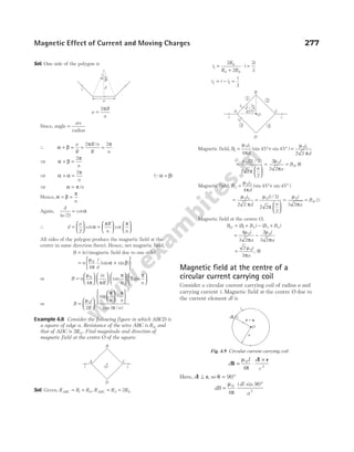
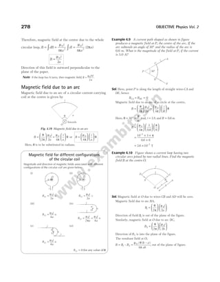
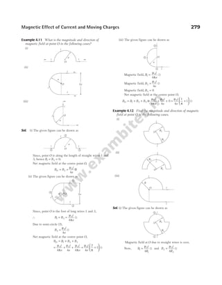
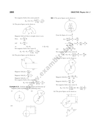
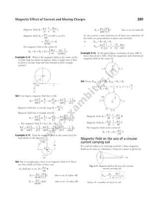
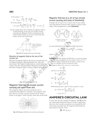
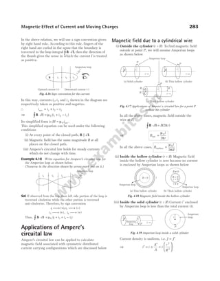
![Hence, at inside point, B l
in⋅ = ′
∫ d i
µ0
⇒ B
ir
R
in = ⋅
µ
π
0
2
2
(iv) Inside the thick portion of hollow cylinder Current
enclosed by the Amperian loop of radius r is
given by i i
A
A
i
r R
R R
′ = ×
′
= ×
−
−
( )
( )
2
1
2
2
2
1
2
Hence, at point P, B l
⋅ = ′
∫ d i
µ0
⇒ B
i
r
r R
R R
in = ⋅
−
−
µ
π
0
2
1
2
2
2
1
2
2
( )
( )
Variation in magnetic field with radius
(i) The variation in magnetic field due to infinite long
solid cylindrical conductor along its radius is as
shown in figure
Note that inside the wire, B = 0 as r = 0.
Also, the magnetic field is continuous at the surface
of the wire.
(ii) The variation in magnetic field due to infinite long
hollow cylindrical conductor along its radius is as
shown in figure
Magnetic field outside the cylindrical conductor does
not depend upon nature (thick/thin or solid/hollow)
of the conductor as well as its radius of cross-section.
Magnetic field due to a solenoid
A cylindrical coil of many wounded turns of insulated
wire with diameter of the coil smaller than its length is
called a solenoid.
A magnetic field is produced around and within the
solenoid as shown in above figure. The magnetic field
within the tightly wound solenoid (ideal solenoid) is
uniform and parallel to the axis of solenoid.
Outside the ideal solenoid, magnetic field is zero as shown
in the figure below
(i) Finite length solenoid If N = total number of
turns, l = length of the solenoid and n = number of
turns per unit length = N l
/ .
Magnetic field inside the solenoid at point P is given by
B
ni
= +
µ
α β
0
2
[sin sin ]
(ii) Infinite length solenoid If the solenoid is of
infinite length and the point is well inside it,
i.e. α β = (π/ )
= 2
Then, B ni
in = µ0
If the solenoid is of infinite length and the point is
near one end, i.e. α = 0 and β π
= ( / ),
2 then
284 OBJECTIVE Physics Vol. 2
B µ
1
r
r = 0 r R
= r
O
B = 0
Bmax
B
r R
>
Fig. 4.22 B-r graph for hollow cylinder
r R
<
r R
=
r = 0 r R
>
B
r
µ B µ
1
r
Bmax
O
B
r
Fig. 4.21 B-r graph for solid cylinder
i
P Loop
P
R1
R2
R2
R1
r
r
Fig. 4.20 Amperian loop inside the thick portion of the
hollow cylinder
i Solenoid i
Fig. 4.23 Solenoid and its magnetic field
B = 0
B
Fig. 4.24 Magnetic field (outside) due to ideal solenoid
r
P
α β
Fig. 4.25 Magnetic field due to finite length solenoid](https://image.slidesharecdn.com/arihantneetobjectivephysicsvolume2bydcpandey2022edition-230417145135-9bce7664/85/Arihant_NEET_Objective_Physics_Volume_2_By_DC_Pandey_2022_Edition-pdf-295-320.jpg)
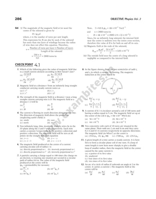
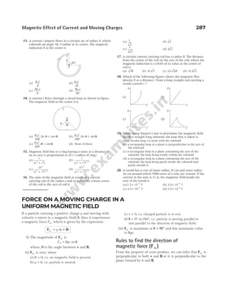
![The exact direction of Fm can be determined by any of the
following methods
(i) Direction of Fm = (sign of q) (direction of v B
× ) ...(i)
We can say that, if q is positive in Eq. (i), magnetic
force is along v B
× and if q is negative, magnetic
force is in a opposite direction to v B
× .
(ii) Fleming’s left hand rule According to this rule, if
the forefinger, the central finger and the thumb of
the left hand are stretched in such a way that they
are mutually perpendicular to each other, then the
central finger gives the direction of velocity of
positive charge ( )
v , forefinger gives the direction of
magnetic field ( )
B and the thumb will give the
direction of magnetic force ( )
Fm .
(iii) Right hand rule Wrap the fingers of your right
hand around the line perpendicular to the plane of v
and B as shown in figure, so that they curl around
with the sense of rotation from v to B through the
smaller angle between them. Your thumb, then points
in the direction of the force Fm on a positive charge.
Note If F v
m ⊥ ⇒F ⊥
ds
dt
. Therefore, Fm d
⊥ s or the work done by the
magnetic force in a static magnetic field is zero.
i.e. WFm
= 0
Example 4.23 A charged particle of specific charge
(i.e. charge per unit mass) 0.2 C/kg has velocity
( $ $)
2 3
i j
− ms−1
at some instant in a uniform magnetic field
( $ $)
5 2
i j
+ T. Find the acceleration of the particle at this
instant.
Sol. The acceleration of the particle, a
F
v B
= = ×
m
q
m
( )
Given,
q
m
= 0.2 C kg
/
v i j
= − −
( $ $)
2 3 1
ms and B i j
= +
( $ $)
5 2 T
Therefore, a i j i j
= − × +
02 2 3 5 2
. ( $ $) ( $ $)
= +
02 4 15
. [ $ $]
k k = −
3 8 2
. $
k ms
Example 4.24 When a proton has a velocity
v i j
= + × −
( $ $)
2 3 106 1
ms , it experiences a force
F k
= ×
– –13
(1.28 10 $ ) N. When its velocity is along the
Z-axis, then it experiences a force along the X-axis. What is
the magnetic field?
Sol. Magnetic force, Fm q
= ×
( )
v B
For Fm to be along ( $)
−k , magnetic field must be along ( $).
−j
Now, substituting all the values in above equation, we get
− × = × +
(1.28 10–13 $ ) [( $ $)
k i j
(1.6 10 )
–19
2 3 × ×
(– $)]
B j 106
∴ 1.28 1.6
= × ×
2 B
or B = =
1.28
3.2
0.4
Therefore, the magnetic field, B j
= − = −
B $ ( $)
0.4 j T
Example 4.25 A charged particle is projected in a magnetic
field
B i j
= + ×
( $ $)
3 4 10–2
T
and the acceleration of the particle is found to be
a i j
= + −
( $ $)
x ms
2 2
.
Find the value of x.
Sol. As, F B
m ⊥
i.e. the acceleration a B
⊥ ⇒ a B
⋅ = 0
or ( $ $) ( $ $)
xi j i j
+ ⋅ + × =
−
2 3 4 10 0
2
or ( )
3 8 10 0
2
x + × =
−
∴ Value of x = −
8
3
Example 4.26 A magnetic field of ( . $ )
4 0 10 3
× −
k T exerts a
force ( . $ . $)
4 0 3 0 10 10
i j
+ × −
N on a particle having a charge
10 9
−
C and moving in the XY-plane. Find the velocity of the
particle.
Sol. Given, B k
= × −
( $ ) ,
4 10 3
T q = −
10 9
C
and magnetic force, F i j
m = + × −
( . $ . $)
4 0 3 0 10 10
N
Let velocity of the particle in XY-plane be
v i + v j
= vx y
$ $
Then, from the relation,
F v B
m q
= ×
( )
( . $ . $) [( $ $) ( $ )]
4 0 3 0 10 10 4 10
10 9 3
i j i j k
+ × = + × ×
− − −
v v
x y
= × − ×
− −
( $ $)
4 10 4 10
12 12
v v
y x
i j
288 OBJECTIVE Physics Vol. 2
v
(Direction of magnetic field)
(Velocity of the charged particle)
B
Fm (Direction of magnetic force)
Fig. 4.29 Direction of Fm by Fleming’s left hand rule
B
Fm
v
Right hand rule
F v B
m = ×
B
v
Fig. 4.30 Direction of Fm by right hand rule](https://image.slidesharecdn.com/arihantneetobjectivephysicsvolume2bydcpandey2022edition-230417145135-9bce7664/85/Arihant_NEET_Objective_Physics_Volume_2_By_DC_Pandey_2022_Edition-pdf-299-320.jpg)
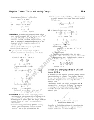
![θ ω α
= =
t B t
0 and r
v
B
= 0
0α
Qα =
q
m
Now, according to the figure,
velocity of the particle at any time t,
v i j
( ) $ $
t v v
x y
= + = +
v v
0 0
cos $ sin $
θ θ
i j
or v i j
( ) cos ( ) $ sin ( ) $
t v B t v B t
= +
0 0 0 0
α α
Position of particle at time t,
r i j
( ) $ $
t x y
= + = + −
r r r
sin $ ( cos )$
θ θ
i j
Substituting the values of r and θ, we get
r i j
( ) [sin ( )$ { cos ( )}$
t
v
B
B t B t
= + −
0
0
0 0
1
α
α α ]
Example 4.35 A charged particle ( , )
q m enters a uniform
magnetic field B at angle α as shown in figure with speed v0.
Find
(i) the angle β at which it leaves the magnetic field,
(ii) time spent by the particle in magnetic field and
(iii) the distance AC.
Sol. (i) Here, velocity of the particle is in the plane of paper
while the magnetic field is perpendicular to the paper
inwards, i.e. angle between v and B is 90°. So, the path is a
circle. The radius of the circle, r
mv
Bq
= 0
Now, O is the centre of the circle.
In ∆AOC, ∠ = ∠
OCD OAD
or 90 90
° − = ° −
β α
∴ β α
=
(ii) ∠ = ∠ =
COD DOA α
(as ∠ = ∠ = ° −
OCD OAD 90 α)
∴ ∠ =
AOC 2α
or length ABC r
mv
Bq
= =
( ) .
2
2 0
α α
∴Time spent by the particle in magnetic field,
t
ABC
v
m
Bq
ABC = =
0
2 α
Alternate method
t
T
ABC =
2
2
π
α
( ) =
⋅
α
π
T
=
α
π
π
2 m
Bq
=
2αm
Bq
(iii) Distance AC AD
= 2 ( ) = 2 ( sin )
r α =
2 0
mv
Bq
sinα
Motion of a charged particle in
combined electric and magnetic
fields : Lorentz force
Consider a point charge q moving with velocity v and is
located at position vector r at a given time t. If electric
field E and magnetic field B are existing at that point, then
force on the electric charge q is given by
F E v B F F
= + × = +
q [ ] electric magnetic
This force was first given by H A Lorentz, hence it is
called Lorentz force.
Here, magnetic force, F v B
m q Bqv
= × =
( ) sin θ and
electric force, F E
e q
= .
The direction of magnetic force is same as that of v B
× , if
charge is positive and opposite to that of v B
× , if charge q
is negative.
Case I When v E
, and B are all collinear
In this situation, the magnetic force on it will be
zero and only electric force will act. So, acceleration,
a
F E
= =
e
m
q
m
.
The particle will pass through the field following a
straight line path (parallel field) with change in its
speed. So, in this situation, speed, velocity,
momentum and kinetic energy all will change without
change in direction of motion as shown below.
Magnetic Effect of Current and Moving Charges 293
β
α
C
B
A
v0
( )
q, m
B
×
×
×
×
×
×
×
×
×
×
×
×
×
×
×
×
×
×
×
×
×
×
×
×
B
D
O
r
90°
90°
r
a
a
v0
C
v0
b
A
a
E
v
B
q
Fig. 4.38 Motion of a charged particle with v E
|| ||B](https://image.slidesharecdn.com/arihantneetobjectivephysicsvolume2bydcpandey2022edition-230417145135-9bce7664/85/Arihant_NEET_Objective_Physics_Volume_2_By_DC_Pandey_2022_Edition-pdf-304-320.jpg)
![Case II When v E
, and B are mutually perpendicular
In this situation, if E and B are such that
F F F
= + =
e m 0, i.e. a F
= =
( )
/m 0.
The particle will pass through the field with same velocity
without any deviation in its path as shown in figure.
In this situation, as F F
e m
= , i e
. .qE qvB
=
v E B
= /
This principle is used in velocity-selector to get a charged
beam having a specific velocity.
Note If only magnetic field is present, we have to put E = 0 ⇒
F v B
= ×
q( ) .
Similarly, if B = 0 ⇒ F E
= q
Example 4.36 A charge particle having charge 2 C is thrown
with velocity ( $ $)
2 3
i j
+ m/s inside a region having E j
= 2$ V/m
and magnetic field 5$
k T. Find the initial Lorentz force
acting on the particle.
Sol. Lorentz force is given by
F E v B
= + ×
q( ) = + + ×
2 2 2 3 5
[ $ ( $ $) $]
j i j k
= + − +
2 2 10 15
[ $ ( $) $]
j j i
= −
( $ $)
30 16
i j N
Example 4.37 A proton beam passes without deviation
through a region of space, where there are uniform
transverse mutually perpendicular electric and magnetic
fields with E = 220 kV/m and B = 50 mT. Then, the beam
strikes a grounded target. Find the force imparted by the
beam on the target if the beam current is equal to
i mA
= 0.80 .
Sol. Since, proton is moving in a straight line, hence net force is
zero.
∴ qE Bqv
=
⇒ v
E
B
=
Also, current associated with the beam,
i ne
= ⇒ n i e
= /
where, n is number of protons/time.
Momentum of a proton = mv
Force, F nmv
=
⇒ F
i m E
eB
= =
× × × × ×
× × ×
− −
− −
0.80
1.6
10 167 10 220 10
10 50 10
3 27 3
19 3
.
= × −
3.67 10 N
5
Cyclotron
Cyclotron is a device used for accelerating positively
charged particle (like α-particles, deutrons, etc.) with the
help of uniform magnetic field upto energy of the order of
MeV. It consists of two hollow metallic dees D1 and D2.
These are placed in a uniform magnetic field which is
perpendicular to the plane of dees. An alternating voltage
is applied between the dees.
As it uses the combination of both the fields (electric and
magnetic), which are perpendicular to each other, hence
are called crossed fields. The charged particle to be
accelerated is produced at centre point between the dees.
The particle accelerates along circular path to acquire
enough energy to carry out nuclear disintegration, etc.
Cyclotron frequency Time taken by ion to describe a
semicircular path is given by
t
r
v
m
qB
= =
π π
Qr
mv
qB
=
IfT = time period of oscillating electric field, then
T t
m
qB
= =
2
2π
∴ Cyclotron frequency, ν
π
= =
1
2
T
qB
m
Note Cyclotron is based on the fact that the time period of one
revolution is independent of its speed or radius of the orbit.
Maximum energy of particle Maximum energy gained
by the charged particle, E
q B
m
r
max =
2 2
0
2
2
where, r0 is maximum radius of the circular path followed
by positive ion.
294 OBJECTIVE Physics Vol. 2
High frequency
oscillator
Target
Deflector
N
S
S
D1
D2 B
E
Dees
Fig. 4.40 Path described by a charged particle in a cyclotron
v
+q +q
B Fm
x
Fe
E
y
z
Fig. 4.39 Motion of a charged particle with v E
⊥ ⊥B](https://image.slidesharecdn.com/arihantneetobjectivephysicsvolume2bydcpandey2022edition-230417145135-9bce7664/85/Arihant_NEET_Objective_Physics_Volume_2_By_DC_Pandey_2022_Edition-pdf-305-320.jpg)
![vector addition, the sum is equal to the vector l directed
from A to D. Thus, F l B
m i
= ×
( )
or we can write, F F D B
ACD AD i
= = ×
( )
A in uniform
magnetic field.
Here, AD = effective length of the wire (Leff ).
Magnetic force on a closed current carrying loop
When a closed current carrying loop is placed in uniform
magnetic field, then the magnetic force on it is always
zero. As the vector sum of dl is always zero, i.e. dl =
∫ 0.
∴ F l B
= × =
∫
i d 0
Magnetic force on different
configurations of the curve
Now, consider magnetic forces on current carrying
conductors of different configurations as shown below.
Here, magnetic force only depends upon effective length
of the wires.
Example 4.41 A wire of length a carries a current i along the
Y-axis. A magnetic field exists which is given by
B i j k)
= + +
B T
0 3 2
( $ $ $
Calculate magnetic force in vector form and its magnitude.
Sol. Length of the wire, l j
= a$
Magnetic force on the wire,
F l B)
= ×
i ( = × + +
i a B
[ $ ( $ $ $ )]
j i j k
0 3 2
= − + +
ia B0 3 0
[ $ $
k i]
= −
B ia
0 3
($ $ )
i k
∴ | | ( ) ( )
F = = + −
F B ia
0
2 2
1 3
= 10 0
B ia
Example 4.42 A square of side 2.0 m is placed in a uniform
magnetic field of 2 0
. T in a direction perpendicular to the
plane of the square inwards. Equal current, i = 3 0
. A is
flowing in the directions shown in figure.
Find the magnitude of magnetic force on the loop.
Sol. Force on wire ACD = Force on AD = Force on AED
All these forces are acting along EC.
∴ Net force on the loop = 3 ( )
FAD
or F i AD B
net = 3( ) ( ) ( ) = ( ) ( . ) ( ) ( . )
3 3 0 2 2 2 0 N = 36 2 N
Example 4.43 A straight wire of length 30 cm and mass
60 mg lies in a direction 30° east of north. The earth’s
magnetic field at this site is horizontal and has a magnitude
of 0.8 G. What current must be passed through the wire, so
that it may float in air? (Take, g ms
= −
10 2
)
Sol. As shown in figure, if a current i is passed through the wire
from end P towards Q, it will experience a force Bi L sin θ
vertically up and hence will float, if
Bil mg
sin θ =
⇒ i
mg
Bl
=
sin θ
=
× ×
× × × ×
=
−
− −
60 10 10
0 8 10 30 10 1 2
50
6
4 2
. /
A
Example 4.44 A straight wire of mass 200 g and length
1.5 m carries a current of 2 A. It is suspended in mid air by
a uniform horizontal magnetic field B. What is the
magnitude of the magnetic field?
Sol. Applying Fleming’s left hand rule, we find that upward
force F of magnitude IlB acts. For mid air suspension, this
must be balanced by the force due to gravity.
∴ mg IlB
= ⇒ B
mg
Il
=
Given, m g
= = = −
200 02 9 8 2
g kg ms
. , . , I l
= =
2 15
A m
, .
Substituting these values in above equation, we get
B =
×
×
=
0.2 9.8
2 1.5
0.65 T
298 OBJECTIVE Physics Vol. 2
L
F
B F
B
i
O a
L
F
B
i
F Bi L
= F i a B
= (2 )
(a) Straight wire (b) Semicircular wire
F BiL
=
(c) Sinusoidal wire
× ×
×
×
×
×
×
×
×
×
×
×
×
×
×
×
×
×
×
×
×
×
×
×
×
×
×
×
×
×
×
×
×
×
×
×
×
×
×
×
×
×
×
×
×
×
i
Fig. 4.45
×
×
×
×
×
×
×
×
×
×
×
×
×
×
×
×
B
C
A E
D
P Q
B
30°
F
mg
i
mg
l
B](https://image.slidesharecdn.com/arihantneetobjectivephysicsvolume2bydcpandey2022edition-230417145135-9bce7664/85/Arihant_NEET_Objective_Physics_Volume_2_By_DC_Pandey_2022_Edition-pdf-309-320.jpg)
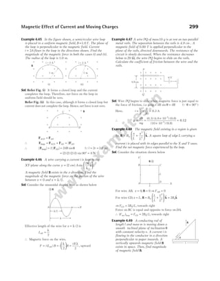
![Sol. Consider the forces acting on the rod as given below
Hence, from figure,
F mg
m cos sin
θ = θ …(i)
Also, F Bil
m = …(ii)
From Eqs. (i) and (ii), we get
B
mg
il
= θ
tan
Force between two parallel
current carrying conductors
Consider two long wires 1 and 2 kept parallel to each
other at a distance r and carrying currents i1 and i2
respectively in the same direction.
Magnetic field on wire 2 due to current in wire 1,
B
i
r
= ⋅
µ
π
0 1
2
(in ⊗ direction)
Magnetic force on a small element dl of wire 2 due to this
magnetic field,
d i d
F l B
= ×
2 ( )
Magnitude of this force,
dF i dl B
= °
2 90
[( ) ( ) sin ] =
i dl
i
r
2
0 1
2
( )
µ
π
= ⋅ ⋅
µ
π
0 1 2
2
i i
r
dl
Direction of this force is alongd l B
× or towards the wire 1.
The force per unit length of wire 2 due to wire 1,
dF
dl
i i
r
=
µ
π
0 1 2
2
The same force acts on wire 1 due to wire 2. The wires
attract each other if currents in the wires are flowing in
the same direction and they repel each other if the
currents are flowing in opposite directions.
Example 4.50 Currents of 10 A and 2 A are passed through
two parallel wires A and B respectively in opposite
directions. If the wire A is infinitely long and length of the
wire B is 2m, then find the force acting on the conductor B
which is situated at 10 cm distance from A.
Sol. Force on a conductor of length l carrying current I2 and
placed at a distance r parallel to another infinitely long
conductor carrying current I1,
F
II
r
l
= ⋅
µ
π
0 1 2
4
2
…(i)
Here, I1 10
= A, I l
2 2 2
= =
A, m, r = =
10 cm 0.1 m
Substituting all these values in Eq. (i), we get
F = ×
× × ×
= ×
− −
10
2 10 2 2
8 10
7 5
0.1
N
Example 4.51 A and B are two infinitely long straight
parallel conductors. C is another straight conductor of length
1m kept parallel to A and B as shown in the figure. Then,
find the magnitude and direction of the force experienced
by C.
Sol. The force between the conductors is attractive, because the
currents in them are in the same direction.
Mutual force between conductors A and C,
F
II l
r
1
0 1 2
2
=
µ
π
=
× ×
µ
π
0
2
2 3 1
0 05
.
= × −
2 40 10 5
. N (towards A)
Mutual force between conductors B and C,
F2
0 5
2
4 3 1
0 08
3 10
= ×
× ×
= × −
µ
π .
N (towards B)
Hence, the resultant force experienced by C,
F F F
C = −
2 1 = − × −
( . )
3 2 4 10 5
N
= × −
0 6 10 5
. N (towards B)
Example 4.52 A long horizontal wire P carries a current of
50 A. It is rigidly fixed. Another fine wire Q is placed
directly above and parallel to P. The weight of wire Q is
0 075 1
. Nm −
and carries a current of 25 A. Find the
perpendicular distance of wire Q from P so that wire Q
remains suspended due to the magnetic repulsion. Also,
indicate the direction of current in Q with respect to P.
300 OBJECTIVE Physics Vol. 2
r
i1 i2
1 2
dl
F
Fig. 4.46 Two long parallel wires carrying currents in
the same direction
N Fm
cos q
Fm (magnetic
force)
F
m
s
i
n
q
mg
mg
mg
sin
(component of )
q
q
q
q
m
g
c
o
s
q
B
F F
i i
b
X Y
×
4 A
3 A
2 A
A C B
8 cm
5 cm](https://image.slidesharecdn.com/arihantneetobjectivephysicsvolume2bydcpandey2022edition-230417145135-9bce7664/85/Arihant_NEET_Objective_Physics_Volume_2_By_DC_Pandey_2022_Edition-pdf-311-320.jpg)
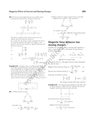
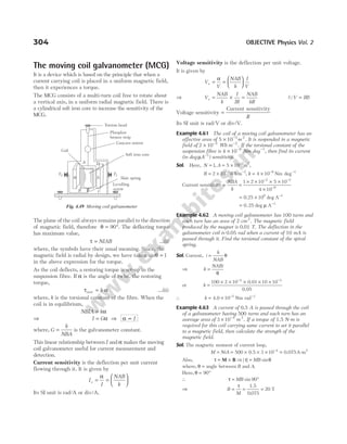
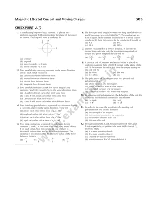
![(A) Taking it together
Assorted questions of the chapter for advanced level practice
1 Biot-Savart’s law indicates that the moving electrons
(velocity, v) produce a magnetic field B such that
[NCERT Exemplar]
(a) B is perpendicular to v
(b) B is parallel to v
(c) it obeys inverse cube law
(d) it is along the line joining the electron and point of
observation
2 In a cyclotron, a charged particle [NCERT Exemplar]
(a) undergoes acceleration all the time
(b) speeds up between the dees because of the magnetic field
(c) speeds up in a dee
(d) slows down within a dee and speeds up between dees
3 A proton is moving along the negative direction of
X-axis in a magnetic field directed along the positive
direction of Y-axis. The proton will be deflected
along the negative direction of
(a) X-axis (b) Y-axis
(c) Z-axis (d) None of these
4 In a co-axial, straight cable, the central conductor
and the outer conductor carry equal currents in
opposite directions. The magnetic field is zero
(a) outside the cable
(b) inside the inner conductor
(c) inside the outer conductor
(d) in between the two conductors
5 A current carrying circular loop of radius R is placed
in the XY-plane with centre at the origin. Half of
the loop with x > 0 is now bent, so that it now lies
in the YZ-plane. Then, [NCERT Exemplar]
(a) the magnitude of magnetic moment now diminishes
(b) the magnetic moment does not change
(c) the magnitude of B at (0,0, z z
), > R increases
(d) the magnitude of B at (0,0, z z R
), >> is unchanged
6 The maximum energy of a deuteron coming out of a
cyclotron is 20 MeV. The maximum energy of
proton that can be obtained from this accelerator is
(a) 10 MeV (b) 20 MeV
(c) 30 MeV (d) 40 MeV
7 A long thin hollow metallic cylinder of radius R has
a current i ampere. The magnetic induction B away
from the axis at a distance r from the axis varies as
shown in
8 The magnetic field at the centre of a circular coil of
radius r carrying current I is B1. The field at the
centre of another coil of radius 2r carrying same
current I is B2. The ratio B B
1 2
/ is
(a) 1/2 (b) 1
(c) 2 (d) 4
9 Three long straight wires A, B and C are carrying
currents as shown in figure. Then, the resultant
force on B is directed
(a) towards A (b) towards C
(c) perpendicular to the plane of paper and outward
(d) perpendicular to the plane of paper and inward
10 A wire of length 2 m carrying a current of 1 A is
bend to form a circle. The magnetic moment of the
coil is (in A m
- 2
)
(a) 2π (b) π/2 (c) π/4 (d) 1/π
11 In hydrogen atom, an electron is revolving in the
orbit of radius 0.53 Å with 66 1015
. × rot/s. Magnetic
field produced at the centre of the orbit is
(a) 0.125 Wb/m2
(b) 1.25 Wb/m2
(c) 12.5 Wb/m2
(d) 125 Wb/m2
12 A circular flexible loop of wire of radius r carrying a
current I is placed in a uniform magnetic field B
perpendicular to the plane of the circle, so that wire
A
d
B C
d
1 A 2 A 3 A
Exercises
Chapter
B
r
(a)
B
r
(b)
B
r
(c)
B
r
(d)](https://image.slidesharecdn.com/arihantneetobjectivephysicsvolume2bydcpandey2022edition-230417145135-9bce7664/85/Arihant_NEET_Objective_Physics_Volume_2_By_DC_Pandey_2022_Edition-pdf-317-320.jpg)
![comes under tension. If B is doubled, then tension in
the loop
(a) remains unchanged (b) is doubled
(c) is halved (d) becomes 4 times
13. A current carrying conductor of length l is bent into
two loops one by one. First loop has one turn of wire
and the second loop has two turns of wire.
Compare the magnetic fields at the centre of the loops.
(a) ′ =
B B
4 (b) 4 ′ =
B B (c) 2 ′ =
B B (d) ′ =
B B
2
14 Two charged particles traverse identical helical paths
in a completely opposite sense in a uniform magnetic
field B k
= B0
$. Then, [NCERT Exemplar]
(a) they have equal z-components of moment
(b) they must have equal charges
(c) they necessarily represent a particle, anti-particle pair
(d) the charge to mass ratio satisfy
e
m
e
m
+
=
1 2
0
15 When a certain length of wire is turned into one
circular loop, then the magnetic field produced at the
centre of coil due to some current flowing, is B1. If
the same wire is turned into three loops to make a
circular coil, then the magnetic induction at the
centre of this coil for the same current will be
(a) B1 (b) 9 1
B (c) 3 1
B (d) 27 1
B
16 A long solenoid carrying a current I is placed with
its axis vertical as shown in the figure. A particle of
mass m and charge q is released from the top of the
solenoid. Its acceleration is (g being acceleration due
to gravity)
(a) greater than g (b) less than g
(c) equal to g (d) None of these
17 A proton moves at a speed v = ×
2 106
m s
/ in a
region of constant magnetic field of magnitude
B = 0 05
. T. The direction of the proton when it
enters this field is θ = °
30 to the field. When you
look along the direction of the magnetic field, then
the path is a circle, projected on a plane perpendicular
to the magnetic field. How far will the proton move
along the direction of B when two projected circles
have been completed?
(a) 4.35 m (b) 0.209 m (c) 2.82 m (d) 2.41 m
18 An electric current i enters and leaves a uniform
circular wire of radius a through diametrically
opposite points. A charged particle q moving along
the axis of the circular wire passes through its centre
at speed v. The magnetic force acting on the particle
when it passes through the centre has a magnitude
(a) qv
i
a
µ0
2
(b) qv
i
a
µ
π
0
2
(c) qv
i
a
µ0
(d) zero
19 A particle of mass m and charge q moves with a
constant velocity v along the positive x-direction. It
enters a region containing a uniform magnetic field
B directed along the negative z-direction, extending
from x a
= to x b
= . The minimum value of v
required, so that the particle can just enter the
region x b
> is
(a) qbB/m (b) q b a B m
( ) /
−
(c) qaB m
/ (d) q b a B m
( ) /
+ 2
20. A proton of mass1.67 10 kg
27
× −
and charge
1.6 10 C
19
× −
is projected in XY-plane with a speed
of 2 106
× m/s at an angle of 60° to the X-axis. If a
uniform magnetic field of 0.14 T is applied along the
Y-axis, then the path of the proton is
(a) a circle of radius 0.2 m and time period π × −
10 7
s
(b) a circle of radius 0.1 m and time period 2 10 7
π × −
s
(c) a helix of radius 0.07 m and time period 0.5 10 s
6
× −
(d) a helix of radius 0.14 m and time period1.0 10 s
7
× −
21 An equilateral triangle of side length l is formed
from a piece of wire of uniform resistance. The
current I is fed as shown in the figure. Then, the
magnitude of the magnetic field at its centre O is
(a)
3
2
0
µ
π
I
l
(b)
3 3
2
0
µ
π
I
l
(c)
µ
π
0
2
I
l
(d) zero
22 An infinitely long conductor is bent into a circle as
shown in figure. It carries a current I ampere and
the radius of loop is R metre. The magnetic
induction at the centre of loop is
(a)
µ
π
π
02
4
1
I
R
( )
+ (b)
µ
π
π
02
4
1
I
R
( )
−
(c)
µ
π
π
0
8
1
I
R
( )
+ (d) zero
Magnetic Effect of Current and Moving Charges 307
I
m, q
O
b
a c
I
R
I](https://image.slidesharecdn.com/arihantneetobjectivephysicsvolume2bydcpandey2022edition-230417145135-9bce7664/85/Arihant_NEET_Objective_Physics_Volume_2_By_DC_Pandey_2022_Edition-pdf-318-320.jpg)
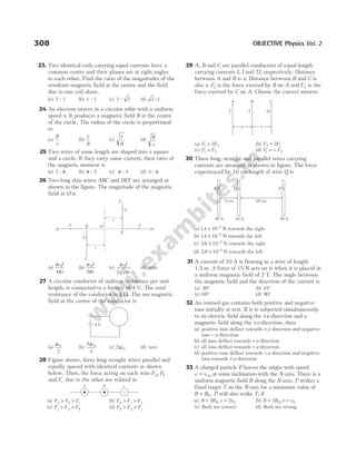
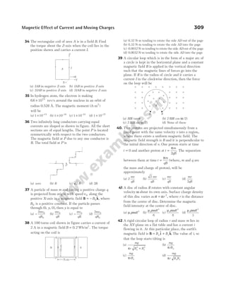
![43 Two circular coils 1 and 2 are made from the same
wire but the radius of the 1st coil is twice that of the
2nd coil. What is the ratio of potential difference
applied across them, so that the magnetic field at
their centres is the same?
(a) 3 : 1 (b) 4 : 1 (c) 6 : 1 (d) 2 : 1
44 A charged particle with specific charge (charge per
unit mass = =
q
m
S) moves undeflected through a
region of space containing mutually perpendicular
uniform electric and magnetic fields E and B. When
the E field is switched off, then the particle will
move in a circular path of radius
(a)
E
BS
(b)
ES
B
(c)
ES
B2
(d)
E
B S
2
45 A large metal sheet carries an electric current along
its surface. Current per unit length is λ.
Magnetic field induction near the metal sheet is
(a) λµ0 (b)
λµ0
2
(c)
λµ
π
0
2
(d)
µ
πλ
0
2
46 A current i = 2A is flowing in a wire frame as shown
in figure. The frame is a combination of two
equilateral triangles ACD and CDE of side 1 m. It is
placed in uniform magnetic field B = 4 T acting
perpendicular to the plane of frame. The magnitude of
magnetic force acting on the frame is
(a) 24 N (b) zero (c) 16 N (d) 8 N
47 A conducting stick of length 2L and mass m is
moving down a smooth inclined plane of inclination
60° with constant speed 5m/s. A current 2A is
flowing in the conductor perpendicular to the paper
inwards. A vertically upward magnetic field B exists
in space there. The magnitude of magnetic field B is
(a)
mg
L
4
(b)
mg
L
(c)
3
4
mg
L
(d)
3
2
mg
L
48 A charge q is moving with a velocity v i
1 = $ m/s at a
point in a magnetic field and experiences a force
F j k
= − +
q[ $ $] N. If the charge is moving with a
velocity v j
2 = $ m/s at the same point, then it
experiences a force F i k
2 = −
q ($ $ ) N. The magnetic
induction B at that point is
(a) ($ $ $ )
i j k
+ + Wb m
/ 2
(b) ($ $ $ )
i j k
− + Wb m
/ 2
(c) ( $ $ $ )
− + −
i j k Wb m
/ 2
(d) ($ $ $ ) /
i j k
+ − Wb m2
49 A square frame of side 1 m carries a current I,
produces a magnetic field B at its centre. The same
current is passed through a circular coil having the
same perimeter as the square. The magnetic field at
the centre of the circular coil is B′. The ratio B B
/ ′ is
(a)
8
2
π
(b)
8 2
2
π
(c)
16
2
π
(d)
16
2 2
π
50 The magnetic field existing in a region is given by
B B k
= +
0 1
x
l
$
A square loop of edge l and carrying current I is
placed with its edges parallel to the X and Y-axes.
The magnitude of the net magnetic force
experienced by the loop is
(a) 2 0
B Il (b) zero
(c) B Il
0 (d) 4 0
B Il
51 Two straight infinitely long current carrying wires
are kept along Z-axis at the coordinates ( , , )
0 0
a and
( , , )
0 0
− a respectively, as shown in the figure. The
current in each of the wire is equal and along
negative Z-axis (into the plane of the paper).
The variation of magnetic field on the X-axis will be
approximately
310 OBJECTIVE Physics Vol. 2
B
60°
Q
P
v
Y
X
a
a
Z
D
C
A
E
× × × × × ×
× × × × × ×
× × × ×
× × × × × ×
× × × × × ×
B
X
B
X
B
X
B
X
(a) (b)
(c) (d)](https://image.slidesharecdn.com/arihantneetobjectivephysicsvolume2bydcpandey2022edition-230417145135-9bce7664/85/Arihant_NEET_Objective_Physics_Volume_2_By_DC_Pandey_2022_Edition-pdf-321-320.jpg)
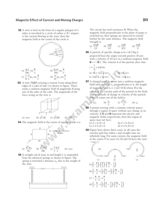
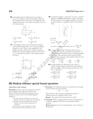
![3 Assertion An α-particle and a deuteron having
same kinetic energy enter in a uniform magnetic
field perpendicular to the field. Then, radius of
circular path of α-particle will be more.
Reason
q
m
ratio of an α-particle is equal to the
q
m
ratio of a deuteron.
4 Assertion In a uniform magnetic field B k
= B0
$, if
velocity of a charged particle is v 0
$
i at t = 0, then it
can have the velocity v 0
$
j at some other instant.
Reason In uniform magnetic field, acceleration of a
charged particle is always zero.
5 Assertion If velocity of charged particle in a
uniform magnetic field at some instant is ( $ $)
a a
1 2
i j
−
and at some other instant is ( $ $),
b b
1 2
i j
+ then
a a b b
1
2
2
2
1
2
2
2
+ = +
Reason Magnetic force cannot change velocity of a
charged particle.
6 Assertion Upper wire shown in figure is fixed. At a
certain distance x, lower wire can remain in
equilibrium.
Reason The above equilibrium of lower wire is
stable equilibrium.
Statement based questions
1 An electron is projected with uniform velocity along
the axis of a current carrying long solenoid. Which
of the following statement(s) is/are correct?
[NCERT Exemplar]
(a) The electron will be accelerated along the axis.
(b) The electron path will be circular about the axis.
(c) The electron will experience a force at 45° to the axis
and hence execute a helical path.
(d) The electron will continue to move with uniform
velocity along the axis of the solenoid.
2 H He and O
+ +
, 2+
ions having same kinetic energy
pass through a region of space filled with uniform
magnetic field B directed perpendicular to the
velocity of ions. The masses of the ions
H He and O
+ + +
, 2
are respectively, in the ratio
1 4 16
: : . Which of the following statement(s) is/are
correct?
(a) H+
ions will be deflected most
(b) O2+
ions will be deflected least
(c) He and O
+ 2+
ions will suffer same deflection
(d) All ions will suffer the same deflection
3 The coil of a moving coil galvanometer has an
effective area of 4 10 2
× −
m2
. It is suspended in a
magnetic field of 5 10 2
× −
Wbm−2
. If deflection in
the galvanometer coil is 0.2 rad when a current of
5 mA is passed through it, then which of the
following statement(s) is/are correct?
(a) Torsional constant is 5 10 6
× −
N-m rad−1
.
(b) Current sensitivity is 40 rad A−1
.
(c) Torsional constant is 3 10 3
× −
N-m rad−1
.
(d) Current sensitivity is 40 deg A−1
.
4 Which of the following statement(s) is/are correct?
I. A flexible wire loop of irregular shape carrying
current when placed in a uniform external magnetic
field acquires a circular shape.
II. For a given perimeter circular shape is having the
greatest area.
(a) Only I (b) Only II
(c) Both I and II (d) None of these
5 Which of the following statement(s) is/are correct?
I. A positive charged particle is rotating in a circle.
Then, magnetic field ( )
B at centre of circle and
magnetic moment ( )
M produced by motion of
charged particle are parallel to each other.
II. M and B are always parallel to each other.
(a) Only I (b) Only II
(c) Both I and II (d) None of these
Match the columns
1 Four particles; α-particle, deuteron, electron and a
Cl−
ion enter in a transverse magnetic field
perpendicular to it with same kinetic energy. Their
paths are as shown in figure. Now, match the
Column I with Column II and mark the correct
option from the codes given below.
Magnetic Effect of Current and Moving Charges 313
x
i2
i1
1
2 3
4](https://image.slidesharecdn.com/arihantneetobjectivephysicsvolume2bydcpandey2022edition-230417145135-9bce7664/85/Arihant_NEET_Objective_Physics_Volume_2_By_DC_Pandey_2022_Edition-pdf-324-320.jpg)
![Column I Column II
(A) Deuteron (p) Path-1
(B) α-particle (q) Path-2
(C) Electron (r) Path-3
(D) Cl−
(s) Path-4
Codes
A B C D A B C D
(a) p q r s (b) q p s r
(c) s r p q (d) q s p r
2 A charged particle is rotating in uniform circular
motion in a uniform magnetic field. Let r = radius of
circle, v = speed of particle, K = kinetic energy,
a = magnitude of acceleration, p = magnitude of
linear momentum,
q
m
= =
α specific charge and
ω = angular speed. Then, match the Column I with
Column II and mark the correct option from the
codes given below.
Column I Column II
(A) If v is doubled (p) r will become two times
(B) If B is doubled (q) ω will become two times
(C) If p is doubled (r) a will become two times
(D) If α is doubled (s) None
Codes
A B C D
(a) p q p q
(b) p r s q
(c) s r s q
(d) p r s s
3 A square current carrying loop abcd is placed near
an infinitely long another current carrying wire ef.
Now, match the Column I with Column II and mark
the correct option from the codes given below.
Column I Column II
(A) Net force on bc and da (p) zero
(B) Net force on ab and cd (q) non-zero
(C) Net force on complete loop abcd (r) rightwards
(D) Net force on ab (s) leftwards
A B C D A B C D
(a) p,s r,q p s (b) q,r q,r r s
(c) p q q,s q,s (d) r r p q
314 OBJECTIVE Physics Vol. 2
a
b
d
c
f
e
(C) Medical entrances’ gallery
Collection of questions asked in NEET & various medical entrance exams
1 A long solenoid of 50 cm length having 100 turns
carries a current of 2.5 A. The magnetic field at the
centre of solenoid is [NEET 2020]
(Take, µ π
0
7
4 10
= × −
T m A−1
)
(a) 314 10 4
. × −
T (b) 6.28 10 5
× −
T
(c) 314 10 5
. × −
T (d) 6.28 10 4
× −
T
2 A cylindrical conductor of radius R is carrying a
constant current. The plot of the magnitude of the
magnetic field B with the distance d from the centre
of the conductor is correctly represented by the
figure [NEET 2019]
3 Two toroids 1 and 2 have total number of turns 200
and 100 respectively with average radii 40 cm and
20 cm, respectively. If they carry same current i, the
ratio of the magnetic fields along the two loops is
[NEET (Odisha) 2019]
(a) 1 : 1 (b) 4 : 1 (c) 2 : 1 (d) 1 : 2
4 A straight conductor carrying current i splits into two
parts as shown in the figure. The radius of the
circular loop is R. The total magnetic field at the
centre P of the loop is [NEET (Odisha) 2019]
(a) zero
(b) 3 32
0
µ i / R, outward
(c) 3 0
µ i /32R, inward
(d)
µ0
2
i
R
, inward
R d
B
R d
B
(a) (b)
R d
B
R d
B
(c) (d)
R
P
90º
i1
i2
i
i](https://image.slidesharecdn.com/arihantneetobjectivephysicsvolume2bydcpandey2022edition-230417145135-9bce7664/85/Arihant_NEET_Objective_Physics_Volume_2_By_DC_Pandey_2022_Edition-pdf-325-320.jpg)
![5 Ionised hydrogen atoms and α-particles with same
momenta enters perpendicular to a constant magnetic
field B. The ratio of their radii of their paths r r
H : α
will be [NEET 2019]
(a) 1 : 2 (b) 4 : 1 (c) 1 : 4 (d) 2 : 1
6 Assertion A charged particle is released from rest
in magnetic field, then it will move in a circular
path. [NEET 2019]
Reason Work done by magnetic field is non-zero.
(a) Both Assertion and Reason are correct and Reason is the
correct explanation of Assertion.
(b) Both Assertion and Reason are correct, but Reason is
not the correct explanation of Assertion.
(c) Assertion is correct, but Reason is incorrect.
(d) Both Assertion and Reason are incorrect.
7 Two circular loops having same radius (R = 10 cm)
and same current
7
2
A are placed along same axis as
shown in the figure. If distance between their
centres is 10 cm, find the value of net magnetic
field at point P. [AIIMS 2019]
(a)
50
5
0
µ
T (b)
28
5
0
µ
T
(c)
5 6
5
0
µ
T (d)
5 6
3
0
µ
T
8 A proton is projected with velocity v i
= 2$ in a region
where magnetic field, B i j k
= + +
($ $ $ )
3 4 µT and electric
field, E i
= 10$µ Vm−1
. Then, find out the net
acceleration of proton. [AIIMS 2019]
(a) 1400 ms−2
(b) 700 ms−2
(c) 1000 ms−2
(d) 800 ms−2
9 Assertion Electron moving perpendicular to B will
perform circular motion.
Reason Force by magnetic field is perpendicular to
velocity. [AIIMS 2019]
(a) Both Assertion and Reason are correct and Reason is the
correct explanation of Assertion.
(b) Both Assertion and Reason are correct but Reason is not
the correct explanation of Assertion.
(c) Assertion is correct but Reason is incorrect.
(d) Both Assertion and Reason are incorrect.
10 If two protons are moving with speed
v = ×
45 105
. ms−1
parallel to each other, then find
the value of ratio of electrostatic and magnetic force
between them. [AIIMS 2019]
(a) 4 4 105
. × (b) 22 105
. × (c) 33 105
. × (d)11 105
. ×
11 A metallic rod of mass per unit length
0.5 kg m−1
is lying horizontally on a smooth inclined
plane which makes an angle of 30° with the
horizontal. The rod is not allowed to slide down by
flowing a current through it, when a magnetic field
of induction 0.25 T is acting on it in the vertical
direction. The current flowing in the rod to keep it
stationary is [NEET 2018]
(a) 14.76 A (b) 5.98 A (c) 7.14 A (d) 11.32 A
12 A long straight wire carrying current I is bent at its
mid-point to form an angle of 45°. Induction of
magnetic field (in tesla) at point P, distant R from
point of bending, is equal to [AIIMS 2018]
(a)
( )
2 1
4
0
− µ
π
I
R
(b)
( )
2 1
4
0
+ µ
π
I
R
(c)
( )
2 1
4 2
0
− µ
π
I
R
(d)
( )
2 1
4 2
0
+ µ
π
I
R
13 An element dl dx
= $
i (where dx = 1cm) is placed at
the origin and carries a large current i = 10 A. What
is the magnetic field on theY-axis at a distance of
0.5 m? [AIIMS 2018]
(a) 2 10 8
× − $
kT (b) 4 10 8
× − $
kT
(c) − × −
2 10 8 $
kT (d) − × −
4 10 8 $
kT
14 The magnetic moment of an electron orbiting in a
circular orbit of radius r with a speed v is equal to
(a) evr/2 (b) evr [JIPMER 2018]
(c) er/2v (d) None of these
15 A current carrying loop is placed in a uniform
magnetic field. The torque acting on it does not
depend upon [JIPMER 2018]
(a) shape of loop (b) area of loop
(c) value of current (d) magnetic field
16 A long wire having a semicircular loop of radius r
carries a current i as shown in figure. The magnetic
induction at the centre O due to entire wire is
[JIPMER 2017]
Magnetic Effect of Current and Moving Charges 315
10 cm
P
10 cm
5 cm
R
P 45°
I
i
i
c
r i e
a d
b
l l
o](https://image.slidesharecdn.com/arihantneetobjectivephysicsvolume2bydcpandey2022edition-230417145135-9bce7664/85/Arihant_NEET_Objective_Physics_Volume_2_By_DC_Pandey_2022_Edition-pdf-326-320.jpg)
![(a)
µ0
4
i
r
(b)
µ0
2
4
i
r
(c)
µ0
2
4
i
r
(d) None of these
17 In the given figure, what is the magnetic field
induction at point O ? [JIPMER 2017]
(a)
µ
π
0
4
I
r
(b)
µ µ
π
0 0
4 2
I
r
I
r
+
(c)
µ µ
π
0 0
4 4
I
r
I
r
+ (d)
µ µ
π
0 0
4 4
I
r
I
r
−
18 A long wire carrying a steady current is bent into a
circular loop of one turn. The magnetic field at the
centre of the loop is B. It is then bent into a circular
coil of n turns. The magnetic field at the centre of
this coil of n turns will be [NEET 2016]
(a) nB (b) n B
2
(c) 2nB (d) 2 2
n B
19 An electron is moving in a circular path under the
influence of a transverse magnetic field of
3.57 × −
10 2
T. If the value of e/m is 1.76 ×10¹¹
C/kg,
the frequency of revolution of the electron is
[NEET 2016]
(a) 1 GHz (b) 100 MHz
(c) 62.8 MHz (d) 6.28 MHz
20 A square loop ABCD carrying a current i is placed
near and coplanar with a long straight conductor XY
carrying a current I, the net force on the loop will be
[NEET 2016]
(a)
µ
π
0
2
Ii
(b)
2
3
0
µ
π
IiL
(c)
µ
π
0
2
IiL
(d)
2
3
0
µ
π
Ii
21 A long straight wire of radius a carries a steady
current I. The current is uniformly distributed over
its cross-section. The ratio of the magnetic fields B
and B′ at radial distances
a
2
and 2 a respectively,
from the axis of the wire is [NEET 2016]
(a)
1
2
(b) 1 (c) 4 (d)
1
4
22 A wire carrying current I has the shape as shown in
adjoining figure. Linear parts of the wire are very
long and parallel to X-axis while semicircular portion
of radius R is lying in YZ-plane. Magnetic field at
point O is [CBSE AIPMT 2015]
(a) B
I
R
= +
µ
π
π
0
4
2
( $ $ )
i k (b) B
I
R
= − −
µ
π
π
0
4
2
( $ $ )
i k
(c) B
I
R
= − +
µ
π
π
0
4
2
( $ $ )
i k (d) B
I
R
= −
µ
π
π
0
4
2
( $ $ )
i k
23 An electron moving in a circular orbit of radius r
makes n rotations per second. The magnetic field
produced at the centre has magnitude
[CBSE AIPMT 2015]
(a)
µ
π
0
2
ne
r
(b) zero
(c)
µ0
2
n e
r
(d)
µ0
2
ne
r
24 Consider the circular loop having current i and with
central point O. The magnetic field at the central
point O is [AIIMS 2015]
(a)
2
3
0
µ
π
i
R
acting downward (b)
5
12
0
µ i
R
acting downward
(c)
6
11
0
µ i
R
acting downward (d)
3
7
0
µ i
R
acting upward
25 A proton is projected with a speed of 3 106
× m/s
horizontally from east to west. An uniform magnetic
field of strength 2 10 3
× −
T exists in the vertically
upward direction. What would be the acceleration of
proton? [UK PMT 2015]
(a) 116 1011 2
. /
× m s (b) 174 1011
. /
× m s
(c) 5 8 1011 2
. /
× m s (d) 2 9 1011 2
. /
× m s
316 OBJECTIVE Physics Vol. 2
i
A D
B C
X
Y
L
I
L
L/2
2R
O
R
I
i
II
I
Z
I
Y
I
I
O
R
X
×
B
I
e
r
r
E
O](https://image.slidesharecdn.com/arihantneetobjectivephysicsvolume2bydcpandey2022edition-230417145135-9bce7664/85/Arihant_NEET_Objective_Physics_Volume_2_By_DC_Pandey_2022_Edition-pdf-327-320.jpg)
![26 The magnetic field at the centre of a circular coil
carrying current I ampere is B. If the coil is bent into
smaller circular coil of n turns, then its magnetic
field at the centre is ′
B . The ratio between ′
B and B
is [Kerala CEE 2015]
(a) 1 : 1 (b) n :1
(c) n2
1
: (d) 2 1
n :
(e) ( ) :
n + 1 1
27 Equal currents are passing through two very long
and straight parallel wires in the same direction.
They will [Guj. CET 2015]
(a) attract each other
(b) repel each other
(c) lean towards each other
(d) Neither attract nor repel each other
28 The variation of magnetic field B due to circular coil
as the distance X varies is shown in the graph.
Which of the following is false? [CG PMT 2015]
(a) Points A and ′
A are known as points of zero curvature
(b) B varies linearly with X at points A and ′
A
(c)
dB
dt
= 0 at points A and ′
A
(d)
d B
dt
2
2
0
= at points A and ′
A
29 Two particles A and B having equal charges, after
being accelerated through the same potential
difference enter into a region of uniform magnetic
field and the particles describe circular paths of radii
R1 and R2, respectively. The ratio of the masses of A
and B is [WB JEE 2015]
(a) R R
1 2
/ (b) R R
1 2
/
(c) ( / )
R R
1 2
2
(d) ( / )
R R
2 1
2
30 There is a ring of radius r having linear charge
density λ and rotating with a uniform angular
velocity ω. The magnetic field produced by this ring
at its own centre would be [UP CPMT 2015]
(a)
λ ω
µ
2
0
2 −
(b)
µ λ ω
0
2
2
(c)
µ λ ω
0
2
(d)
µ λ
ω
0
2
2
31 Two particles A and B having equal charges + 6 C
after being accelerated through the same potential
difference, enter in a region of uniform magnetic
field and describe circular paths of radii 2 cm and
3 cm, respectively. The ratio of mass of A to that of
B is [Manipal 2015]
(a) 1/3 (b) 1/2 (c) 4/9 (d) 9/5
32 A proton beam enters a magnetic field of10 4
−
Wb/m2
normally. If the specific charge of the proton is
1011
C/kg and its velocity is 109
m/s, then the radius
of the circle described will be [KCET 2015]
(a) 100 m (b) 0.1 m (c) 1 m (d) 10 m
33 A cyclotron is used to accelerate [KCET 2015]
(a) Only negatively charged particles
(b) neutron
(c) Both positively and negatively charged particles
(d) Only positively charged particles
34 Two parallel beams of positron moving in the same
direction will [Manipal 2015]
(a) not interact with each other
(b) repel each other
(c) attract each other
(d) be deflected normal to the plane containing two beams
35 Two concentric coils each of radius equal to 2π cm
are placed at right angles to each other. If 3A and
4A are the currents flowing through the two coils,
respectively. The magnetic induction (in Wb/m2
) at
the centre of the coils will be [KCET 2015]
(a) 5 10 5
× −
(b) 12 10 5
× −
(c) 7 10 5
× −
(d) 10 5
−
36 Two identical long conducting wires AOB and COD
are placed at right angle to each other with one
above other such that O is the common point for the
two. The wires carry I1 and I2 currents, respectively.
Point P is lying at distance d from O along a
direction perpendicular to the plane containing the
wires. The magnetic field at the point P will be
[CBSE AIPMT 2014]
(a)
µ
π
0 1
2
2 d
I
I
(b)
µ
π
0
1 2
2 d
I I
( )
+
(c)
µ
π
0
1
2
2
2
2 d
I I
( )
− (d)
µ
π
0
1
2
2
2 1 2
2 d
I I
( ) /
+
37 A solenoid has length 0.4 cm, radius 1 cm and
400 turns of wire. If a current of 5 A is passed
through this solenoid, then what is the magnetic
field inside the solenoid? [KCET 2014]
(a) 628 10 4
. × −
T (b) 628 10 1
. × −
T
(c) 628 10 7
. × −
T (d) 628 10 6
. × −
T
38 A toroid having 200 turns carries a current of 1A.
The average radius of the toroid is 10 cm. The
magnetic field at any point in the open space inside
the toroid is [Kerala CEE 2014]
(a) 4 10 3
× −
T (b) zero
(b) 0.5 10 T
3
× −
(d) 3 10 3
× −
T
(e) 2 10 3
× −
T
Magnetic Effect of Current and Moving Charges 317
A′ A
X= 0](https://image.slidesharecdn.com/arihantneetobjectivephysicsvolume2bydcpandey2022edition-230417145135-9bce7664/85/Arihant_NEET_Objective_Physics_Volume_2_By_DC_Pandey_2022_Edition-pdf-328-320.jpg)
![39 The magnetic field due to a current carrying circular
loop of radius 3 cm at a point on the axis at a
distance of 4 cm from the centre is 54 µT. What will
be its value at the centre of the loop? [UK PMT 2014]
(a) 200 µT (b) 250 µT (c)125 µT (d) 75 µT
40 A proton of mass m and charge q is moving in a
plane with kinetic energy E. If there exists a
uniform magnetic field B perpendicular to the plane
motion, the proton will move in a circular path of
radius [WB JEE 2014]
(a)
2Em
qB
(b)
2Em
qB
(c)
Em
qB
2
(d)
2Eq
qB
41 If the velocity of charged particle has both
perpendicular and parallel components while moving
through a magnetic field, then what is the path
followed by a charged particle? [KCET 2014]
(a) Circular (b) Elliptical (c) Linear (d) Helical
42 A particle with charge q is moving along a circle of
radius R with uniform speed v. The associated
magnetic moment µ is given by [EAMCET 2014]
(a)
1
2
2
v R (b)
1
4
qvR (c)
1
2
qvR (d)
1
2
2
q vR
43 A charged particle of mass m and charge q moves
along a circular path of radius r that is perpendicular
to a magnetic field B. The time taken by the particle
to complete one revolution is [UK PMT 2014]
(a)
2µmq
B
(b)
2 2
πq B
m
(c)
2πqB
m
(d)
2πm
qB
44 Magnetic induction produced at the centre of a
circular loop carrying current is B. The magnetic
moment of the loop of radius R is
(where, µ0 = permeability of free space)
[MHT CET 2014]
(a)
BR2
0
2πµ
(b)
2 3
0
π
µ
BR
(c)
BR2
0
2πµ
(d)
2 2
0
π
µ
BR
45 In cyclotron, for a given magnet, radius of the
semicircle traced by positive ion is directly
proportional to (where, v = velocity of positive ion)
[MHT CET 2014]
(a) v−2
(b) v−1
(c) v (d) v2
46 When a magnetic field is applied on a stationary
electron, then it [Kerala CEE 2014]
(a) remains stationary
(b) spins about its own axis
(c) moves in the direction of the field
(d) moves perpendicular to the direction of the field
(e) moves opposite to the direction of the field
47 An electron in a circular orbit of radius 0.05 nm
performs1016
rev/s. The magnetic moment due to
this rotation of electron is (in A-m2
) [WB JEE 2014]
(a) 2 16 10 23
. × −
(b) 3 21 10 22
. × −
(c) 3 21 10 24
. × −
(d) 1 26 10 23
. × −
48 A circular coil of radius 10 cm and 100 turns carries
a current 1 A. What is the magnetic moment of the
coil? [KCET 2014]
(a) 3 142 104
. × 2
A m
- (b) 104
A-m2
(c) 3 142
. A m
- 2
(d) 3 A m
- 2
49 Two thin long conductors separated by a distance d
carry currents I1 and I2 in the same direction. They
exert a force F on each other. Now, the current in
one of them is increased to two times and its
direction is reversed. The distance is also increased
to 3d. The new value of force between them is
[UK PMT 2014]
(a) −2F (b)
F
3
(c) −
2
3
F
(d) −
F
3
50 A charged particle experiences magnetic force in the
presence of magnetic field. Which of the following
statement is correct? [KCET 2014]
(a) The particle is moving and magnetic field is
perpendicular to the velocity
(b) The particle is moving and magnetic field is parallel to
the velocity
(c) The particle is stationary and magnetic field is
perpendicular to the velocity
(d) The particle is stationary and magnetic field is parallel
to the velocity
51 The ratio of magnetic dipole moment of an electron
of charge e and mass m in Bohr’s orbit in hydrogen
atom to its angular momentum is [MHT CET 2014]
(a)
e
m
(b)
m
e
(c)
2m
e
(d)
e
m
2
52 A wire of length L metre carrying a current I ampere
is bent in the form of a circle. The magnitude of the
magnetic moment is [EAMCET 2014]
(a)
L I
2 2
4π
(b)
LI
4π
(c)
L I
2
4π
(d)
LI
4π
53 A long conducting wire carrying a current I is bent
at120° (see figure). The magnetic field B at a point P
on the right bisector of bending angle at a distance d
from the bend is (µ0 is the permeability of free
space) [MP PMT 2014]
318 OBJECTIVE Physics Vol. 2
d
P
I
I
120°](https://image.slidesharecdn.com/arihantneetobjectivephysicsvolume2bydcpandey2022edition-230417145135-9bce7664/85/Arihant_NEET_Objective_Physics_Volume_2_By_DC_Pandey_2022_Edition-pdf-329-320.jpg)
![(a)
2
2
0
µ
π
I
d
(b)
µ
π
0
2
I
d
(c)
µ
π
0
3
I
d
(d)
3
2
0
µ
π
I
d
54 When a proton is released from rest in a room, it
starts with an initial acceleration a0 towards west.
When it is projected towards north with a speed v 0,
it moves with an initial acceleration 3 0
a towards
west. The electric and magnetic fields in the room
are [NEET 2013]
(a)
ma
e
ma
ev
0 0
0
2
west, up (b)
ma
e
ma
ev
0 0
0
2
west, down
(c)
ma
e
ma
ev
0 0
0
3
east, up (d)
ma
e
ma
ev
0 0
0
3
east, down
55 A current loop in a magnetic field [NEET 2013]
(a) experiences a torque whether the field is uniform or
non-uniform in all orientations
(b) can be in equilibrium in one orientation
(c) can be equilibrium in two orientations, both the
equilibrium states are unstable
(d) can be in equilibrium in two orientations, one stable
while the other is unstable
56 A proton and helium nucleus are shot into a
magnetic field at right angles to the field with same
kinetic energy. Then, the ratio of their radii is
[KCET 2013]
(a) 1 : 1 (b) 1 : 2 (c) 2 : 1 (d) 1 : 4
57 Two charged particles have charges and masses in
the ratio 2 : 3 and 1 : 4, respectively. If they enter a
uniform magnetic field and move with the same
velocity, then the ratio of their respective time
periods of revolution is [Kerala CEE 2013]
(a) 3 : 8 (b) 1 : 4 (c) 3 : 5 (d) 1 : 6
(e) 2 : 5
58 A current of 2 A is made to flow through a coil
which has only one turn. The magnetic field
produced at the centre is 4 10 6
π × −
Wb/m2
. The
radius of the coil is [MP PMT 2013]
(a) 0.0001m (b) 0.01m (c) 0.1m (d) 0.001 m
59 A long straight wire is carrying a current of 12 A.
The magnetic field at a distance of 8 cm is
(µ π
0
2
4
= × −
10 N A )
7
[J & K CET 2013]
(a) 2 10 4
× −
Wb/m2
(b) 3 10 5 2
× −
Wb m
/
(c) 4 10 4 2
× −
Wb m
/ (d) 4 10 5 2
× −
Wb m
/
60 The magnetic field at a point on the axis of a long
solenoid having 5 turns per cm length when a current
of 0.8 A flows through it is [J & K CET 2013]
(a) 5 024 10 4 2
. /
× −
Wb m (b) 6 024 10 4
. /
× − 2
Wb m
(c) 7024 10 4 2
. /
× −
Wb m (d) 8 024 10 4
. /
× − 2
Wb m
61 In the diagram, I I
1 2
, are the strength of the currents
in the loop and straight conductors respectively,
OA AB R
= = . The net magnetic field at the centre O
is zero, then the ratio of the currents in the loop and
the straight conductor is [KCET 2013]
(a) π (b) 2π (c)
1
π
(d)
1
2π
62 Two straight wires each 10 cm long are parallel to
one another and separated by 2 cm. When the
current flowing in them is 30 A and 40 A
respectively, then the force experienced by either of
the wires is [J & K CET 2013]
(a) 1.2 × −
10 3
N (b) 12 10 3
× −
N
(c) 11 2 10 3
. × −
N (d) 10 2 10 3
. × −
N
63 A charged particle with a velocity 2 103
× ms−1
passes undeflected through electric field and
magnetic fields in mutually perpendicular directions.
The magnetic field is 15 T. The magnitude of
electric field will be [Karnataka CET 2013]
(a) 1.5 NC
× −
103 1
(b) 2 103 1
× −
NC
(c) 3 103 1
× −
NC (d) 1.33 NC
× −
103 1
64 Two similar coils of radius R are lying concentrically
with their planes at right angles to each other. The
current flowing in them are I and 2I, respectively.
The resultant magnetic field induction at the centre
will be [CBSE PMT 2012]
(a)
5
2
0
µ I
R
(b)
3
2
0
µ I
R
(c)
µ0
2
I
R
(d)
µ0I
R
65 The adjacent figure shows the cross-section of a long
rod with its length perpendicular to the plane of the
paper. It carries constant current flowing along its
length. B B B
1 2 3
, , and B4 respectively, represent the
magnetic fields due to the current in the rod at
points 1, 2, 3 and 4 lying at different separations
from the centre O, as shown in the figure. Which of
the following shall hold true? [AMU 2012]
Magnetic Effect of Current and Moving Charges 319
I1
O
R
A
R
B
I2](https://image.slidesharecdn.com/arihantneetobjectivephysicsvolume2bydcpandey2022edition-230417145135-9bce7664/85/Arihant_NEET_Objective_Physics_Volume_2_By_DC_Pandey_2022_Edition-pdf-330-320.jpg)
![(a) B B
1 2 0
> ≠ (b) B B
2 3 0
> ≠
(c) B B B
1 2 3 0
= = ≠ (d) B B
3 4 0
> ≠
66 A wire of one metre length carries a constant
current. The wire is bent to form a circular loop.
The magnetic field at the centre of this loop is B.
The same is now bent to form a circular loop of
smaller radius having four turns. The magnetic field
at the centre of this new loop will be [BHU 2012]
(a)
B
2
(b) 4B (c)
B
4
(d) 16B
67 A proton is moving in a uniform magnetic field B in
a circular path of radius a in a direction
perpendicular to Z-axis along which field B exists.
Calculate the angular momentum, if the radius is a
and charge on proton is e. [Manipal 2012]
(a)
Be
a2
(b) eB a
2
(c) a eB
2
(d) aeB
68 The magnetic field in a certain region of space is
given by B i
= × −
8.35 10 2 $ T. A proton is shot into
the field with velocity v i j
= × + ×
( $ $)
2 10 4 10
5 5
m/s.
The proton follows a helical path in the field. The
distance moved by proton in the x-direction during
the period of one revolution in the YZ-plane will be
(Take, mass of proton = × −
1.67 10 27
kg) [AMU 2012]
(a) 0.053 m (b) 0.136 m (c) 0.157 m (d) 0.236 m
69 A planar coil having 12 turns carries 15 A current.
The coil is oriented with respect to the uniform
magnetic field B i
= 0 2
. $ T such that its directed area
is A i 2
= 0 04
. $ m . The potential energy of the coil in
the given orientation is [AMU 2012]
(a) 0 (b) + 0 72
. J (c) +144
. J (d) −144
. J
70 A current i ampere flows along the inner conductor
of a co-axial cable and returns along the outer
conductor of the cable, then the magnetic induction
at any point outside the conductor at a distance
r metre from the axis is [JCECE 2012]
(a) ∞ (b) zero (c)
µ
π
0
4
2i
r
(d)
µ
π
π
0
4
2 i
r
71 Two parallel long wires carry currents i1 and i2 with
i i
1 2
> . When the currents are in the same direction,
then the magnetic field midway between the wires
is 10 µT. When the direction of i2 is reversed, then
it becomes 40 µT. Then, ratio of i i
1 2
/ is [JCECE 2012]
(a) 3 4
: (b) 5 3
:
(c) 7 11
: (d) 11 7
:
72 When an electron beam passes through an electric
field, they gain kinetic energy. If the same electron
beam passes through a magnetic field, then their
[BHU 2012]
(a) energy and momentum both ramain unchanged
(b) potential energy increases
(c) momentum increases
(d) kinetic energy increases
73 If a steel wire of length l and magnetic moment M is
bent into a semicircular arc, the new magnetic
moment is [JCECE 2012]
(a) M l
× (b)
M
l
(c)
2M
π
(d) M
74 A proton travelling at 23° w.r.t. the direction of a
magnetic field of strength 2.6 mT experiences a
magnetic force of 6.5 10 17
× −
N. What is the speed
of the proton? [DUMET 2011]
(a) 2 105
× ms 1
−
(b) 4 105
× ms 1
−
(c) 6 105
× ms 1
−
(d) 6 10 5
× −
ms 1
−
75 What uniform magnetic field applied
perpendicular to a beam of electrons moving at
13 106
. × ms 1
−
, is required to make the electrons
travel in a circular arc of radius 0.35 m?
[DUMET 2011]
(a) 2.1× −
10 5
G (b) 6 10 5
× −
T
(c) 2.1× −
10 5
T (d) 6 10 5
× −
G
76 Two very long straight parallel wires carry currents i
and 2i in opposite directions. The distance between
the wires is r. At a certain instant of time, a point
charge q is at a point equidistant from the two wires
in the plane of the wires. Its instantaneous velocity v
is perpendicular to this plane. The magnitude of the
force due to the magnetic field acting on the charge
at this instant is [KCET 2011]
(a) zero (b)
3
2
0
µ
π
iqv
r
(c)
µ
π
0 iqv
r
(d)
µ
π
0
2
iqv
r
77 The torque required to hold a small circular coil of
10 turns, area 1 mm2
and carrying a current of
( / )
21 44 A in the middle of a long solenoid of
10 turns / m
3
carrying a current of 2.5 A with its
axis perpendicular to the axis of the solenoid is
[KCET 2011]
(a) 1.5 10 6
× −
N-m (b) 1.5 × −
10 8
N-m
(c) 1.5 × +
10 6
N-m (d) 1.5 × +
10 8
N-m
320 OBJECTIVE Physics Vol. 2
Solenoid
B
Coil
Axis
O 1 2 3 4](https://image.slidesharecdn.com/arihantneetobjectivephysicsvolume2bydcpandey2022edition-230417145135-9bce7664/85/Arihant_NEET_Objective_Physics_Volume_2_By_DC_Pandey_2022_Edition-pdf-331-320.jpg)
![l CHECK POINT 4.1
3 (c) Magnetic field at a distance r near a long straight current
carrying wire is given by
B
i
r
= ⋅
µ
π
0
4
2
⇒ B
r
∝
1
∴
B
B
r
r
1
2
2
1
= or
B
B
r
r
2
2
=
/
⇒ B B
2 2
=
4 (d) Using Fleming’s right-hand rule, the direction of magnetic
field is towards west.
5 (a) According to right hand screw rule,
Along the line x y
= , magnetic field due to two wires will be
equal and opposite.
6 (b) Magnetic field at the centre of a current carrying circular
coil of N turns is given by
B
Ni
r
=
µ0
2
⇒B
r
∝
1
7 (b) Current produced in wire, i
q
t
e
= =
×
100
1
∴ i e
= 100
Magnetic field at the centre of circular path,
= ⋅
µ
π
π
0
4
2 i
r
= ⋅
×
=
×
µ
π
π µ
0 0
4
2 100 200
4
e
r
e
r
=
× × ×
×
−
µ0
19
200 16 10
4 0 8
.
.
= −
10 17
0
µ T
8 (c) The direction of magnetic field produced due to both
semicircular parts will be perpendicular to the paper and
inwards.
Magnetic induction at the centre O,
B B B
= +
1 2 = +
µ µ
0
1
0
2
4 4
i
r
i
r
=
+
µ0 1 2
1 2
4
i r r
r r
9 (c) Magnetic field at the centre of circular coil of N turns is
given by
B
Ni
r
=
µ0
2
=
× × ×
× ×
−
−
4 10 100 01
2 5 10
7
2
π .
= × −
4 10 5
π T
10 (d) The given situation is shown below
At centre O, magnetic field due to inner circular coil,
B
Ni
r
1
0 1
1
0
2 0
2
10
2 2 10
50
= =
×
× ×
=
−
µ µ
µ
(
( )
0.2)
u
Similarly, at centre O, magnetic field due to outer circular coil,
B
Ni
r
2
0 2
2
0
2
0
2
10
2 4 10
75
2
= =
×
×
= ⊗
−
µ µ µ
( )
( )
0.3
Net magnetic field, B B B
O = −
1 2 = −
50
75
2
0
0
µ
µ
=
−
=
100 75
2
25
2
0 0
0
2
µ µ
µ Wb/m u
11 (c) The magnetic field, B
Ni
R
=
µ0
2
or B
N
R
∝
B
B
N
N
R
R
N
N
R
R
2
1
2
1
1
2
1
1
1
1
2
2
4
= × = × =
/
⇒ B B B
2 1
4 4
= =
B B
′ = 4
12 (b) Magnetic field at the centre of arc,
B
i
r
=
µ
π
θ
0
4
= × ×
µ
π
π
0
4 2
i
R
=
µ0
8
i
R
13 (d) Magnetic field induction at centre O is given by
B =
3
4
( )
Magnetic field due to whole circle
=
=
3
4 2
3
8
0 0
µ µ
i
R
i
R
14 (a) The magnetic field at the centre O,
B B B
O = +
1 2
=
−
+ +
µ π θ
π
µ
π
θ θ
0 0
2
2 2
2 4
I
R
I
r
[sin sin ]
=
−
+
µ π θ
π
µ
π θ
θ
0 0
2 4
2
I
R
I
R
( cos )
( sin )
= − +
µ
π
π θ θ
0
2
I
R
[ tan ]
W E
N
S
W
i
i
x y
=
2
r
q
q
I
O
R
A
B O 2 cm
4 cm
0.2A
0.3A
p/2
O
R
3p
2
i
Hints & Explanations](https://image.slidesharecdn.com/arihantneetobjectivephysicsvolume2bydcpandey2022edition-230417145135-9bce7664/85/Arihant_NEET_Objective_Physics_Volume_2_By_DC_Pandey_2022_Edition-pdf-333-320.jpg)
![11 (c) Radius of particle, r
Km
Bq
=
2
∴Area bounded by the path, A r
Km
B q
= =
π
π
2
2 2
2
or A K
∝
12 (b) Velocity is in XY-plane and magnetic field along Z-axis.
Therefore, path of the electron in magnetic field will be a
circle. Magnetic force cannot change the speed of a particle
but direction of its motion continuously changes. Hence, path
of electron will change.
13 (b) Radius of helical path taken by proton beam,
r
Mv
Bq
=
°
=
× × × °
×
sin 60 167 10 4 10 60
0 3 1
27 5
( . ) ( ) sin
. .
–
6 10 19
× –
= .
0 012 m
14 (a) For charged particle on circular path,
mv
r
qvB
2
=
∴ r
mv
qB
= =
2mE
qB
For proton, R
m E
qB
p
p
=
2
…(i)
For deuteron, R
m E
qB
d
d
=
2
…(ii)
Dividing Eq. (ii) by Eq. (i), we get
R
R
m
m
d
p
d
p
= = 2 [Qm m
d p
= 2 ]
∴ R R
d p
= 2
15 (a) Radius of the circular path, r
mv
qB
=
⇒
r
r
m v
m v
q
q
1
2
1 1
2 2
2
1
= × =
×
×
× =
1 2
1 3
2
1
4
3
16 (a) Frequency of revolution, f
Bq
m
=
2π
i.e. f
q
m
∝
As q is same for all given particles, f
m
∝
1
. Mass of Li+
is
maximum, therefore its frequency will be minimum.
l CHECK POINT 4.3
1 (b) Applying Fleming’s left-hand rule,
if magnetic field is perpendicular to
paper inwards and current in the loop
is clockwise, the magnetic force F on
each element of loop is radially
outwards and loop has a tendency to
expand outwards.
Also, when a current carrying loop is
placed in uniform magnetic field, then
net force on it is zero and loop cannot have translation motion.
2 (d) The parallel wires carrying currents in the same direction
attract each other because magnetic forces on the two wires
act towards each other.
3 (b) Two parallel conductor A and B of equal length carry
currents I and 10I, respectively in the same direction, then A
and B attract each other with same force.
4 (c) Force per unit length,
F
l
ii
d
= ⋅
µ
π
0 12
4
2
F
l
i
d
= ⋅
µ
π
0
2
4
2
( )
Qi i i
= =
1 2
F
l
i
d
= ⋅
µ
π
0
2
2
(attractive)
5 (d) Force between two conductors, F
II
d
∝ 1 2
When I1 is changed to 2 1
I and d is changed to 3d.
∴ F
I I
d
F
′ ∝ ∝
( ) ( )
2
3
2
3
1 2
As, direction of current is reversed, so F F
′ = − 2 3
/ .
6 (c) Force per unit length,
F
l
i i
r
A B
=
µ
π
0
2
Given, i i
A B
= 2
∴ (0.004)
.
–
=
×
2 10
0 01
2
7
2
( )
iB
∴ iB = 10 A
7 (c) Torque, τmax = NiAB = × × ×
1 2
i r B
π
Q 2
2
π
π
r L r
L
= ⇒ =
∴ τ π
π π
max =
=
i
L
B
L iB
2 4
2 2
8 (d) Torque acting on the coil is given by
τ θ
= NiBA sin
As, magnetic field is normal to the plane of coil.
So, θ = °
0
∴ τ = 0
9 (d) The pole pieces of the magnet used in a pivoted coil
galvanometer are cylindrical surfaces of a horse-shoe magnet.
10 (b) The electrical current in moving coil galvanometer
i
k
NAB
=
θ
⇒ i ∝ θ
11 (b) We have sensitivity of a moving coil galvanometer
S
NAB
k
=
where, k is the torsional constant of its suspension.
In order to increase the sensitivity of a moving coil
galvanometer, one should decrease the torsional constant of
its suspension.
324 OBJECTIVE Physics Vol. 2
F F
F F
y](https://image.slidesharecdn.com/arihantneetobjectivephysicsvolume2bydcpandey2022edition-230417145135-9bce7664/85/Arihant_NEET_Objective_Physics_Volume_2_By_DC_Pandey_2022_Edition-pdf-335-320.jpg)
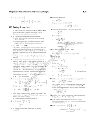
![18 (d) Velocity vector is parallel to magnetic field vector.
∴ θ = °
0
Hence, force, F Bqv
= =
sin0 0
19 (b) We have, ( )
b a r
mv
Bq
− = =
∴ v
b a Bq
m
min
( )
=
−
20 (c) Radius of circular path,
r
mv
Bq
=
°
cos 60
=
× × °
× ×
( . ) ( )
. .
–
–
167 10 2 10 60
014 16 10
27 6
19
cos
= .
0 07 m
and T
m
Bq
= =
×
× ×
2 2 167 10
014 16 10
27
19
π π
( ) ( . )
. .
–
–
= ×
0 5 10 6
. –
s
21 (d) Distribution of current will be as shown below.
Net magnitude of magnetic field at the centre O is given by
B B B B
ab bc ac
net = + −
= ⋅ + ⋅ − ⋅
µ
π
µ
π
µ
π
0 0 0
2
3
2
3
2
2 3
I
CO
I
AO
I
BO
/ / /
= ⋅ + ⋅ − ⋅
µ
π
µ
π
µ
π
0 0 0
2
3
2
3
2
2 3
I
r
I
r
I
r
/ / /
[QAO BO CO r
= = = ]
= 0
22 (a) B = (due to circular wire) + (due to straight wire)
= +
µ µ
π
0 0
2 2
I
R
I
R
= +
= +
µ
π
µ
π
π
0 0
2
1
1 2
4
1
I
R
I
R
( )
23 (d) The magnitude of the resultant magentic field at the
common centre of coil is given as B B
net = 2
The ratio of the magnitude of the resultant magnetic field at
the common centre and the magnetic field due to one coil
alone at common centre.
⇒
B
B
B
B
net
at centre
= =
2 2
1
24 (c) Magnetic field, B
i
R
ef
R
= =
µ µ
0 0
2 2
( )
=
( ) ( )
µ
π
0
2
e
v
R
R
⇒ R
ev
B
2
2
=
µ
π
⇒ R
v
B
2
∝
⇒ R
v
B
∝
25 (c) Let the length of each wire be L.
For square, length of each side = L/4
Area of square =
=
L L
4 16
2 2
For circle, L r
= 2 π ⇒ r
L
=
2 π
Area of circle = =
=
π π
π π
r
L L
2
2 2
2 4
As, magnetic moment, M iA
=
⇒ M A
∝
∴
M
M
A
A
square
circle
square
circle
= = =
L
L
2
2
16
4 4
/
/ π
π
26 (b) At O, due to wire AB and DE, magnetic field will be zero.
The combined effect of BC and DF is equivalent to that of an
infinitely long wire, i.e. both fields are in same direction.
⇒ B
I
r
I
r
O = =
2
4 2
0 0
µ
π
µ
π
27 (d) The given figure is as shown
R
R
1
2
1
3
= [Q Resistance, R l
∝ ]
⇒
I
I
R
R
1
2
2
1
3
= = [QV = 4V]
∴ B
I
r
1
0 1
2
90
360
= ×
°
µ
⊗ and B
I
r
2
0 2
2
270
360
= ×
µ
.
∴
B
B
I
I
1
2
1
2
90
270
3
1
3
1
= × = × =
or B B
1 2
⊗ = u
∴Net magnetic field at centre of conductor is zero.
28 (b) F F F
I l
d
I l
d
I l
d
a ab ac
= − = − =
µ
π
µ
π
µ
π
0
2
0
2
0
2
2 2 2 4
( )
F F F
I l
d
I l
d
I l
d
b ba bc
= + = + =
µ
π
µ
π
µ
π
0
2
0
2
0
2
2 2
326 OBJECTIVE Physics Vol. 2
I2
270°
90°
I1
4 V
I
d d
a b c
a c
b
O
I
3
I I
I
3
2
3
I
A
C
B
B
B
B = B
net √2](https://image.slidesharecdn.com/arihantneetobjectivephysicsvolume2bydcpandey2022edition-230417145135-9bce7664/85/Arihant_NEET_Objective_Physics_Volume_2_By_DC_Pandey_2022_Edition-pdf-337-320.jpg)
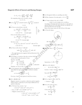
![∴
µ
π
π µ
π
π
0 1
1
0 2
2
4
2
4
2
i
r
i
r
= or
i
r
i
r
1
1
2
2
=
As, r r
1 2
2
=
∴
i
r
i
r
1
2
2
2
2
= or i i
1 2
2
=
Now, ratio of potential differences,
V
V
i R
i R
i R
i R
2
1
2 2
1 1
2 2
2 2
2 2
1
4
=
×
×
=
×
×
=
[Q Resistance, R r
∝ (radius)]
⇒
V
V
1
2
4
1
=
44 (d) Velocity,v
E
B
= and radius of path,
r
mv
Bq
v
B q m
E B
B S
E
B S
= =
⋅
=
⋅
=
/
/
2
45 (b) Applying Ampere’s circuital law in the closed loop as
shown in figure,
2 0
Bl l
= ⋅
µ λ
( )
∴ Magnetic field induction, B =
µ λ
0
2
46 (a) We have, F F F
CAD CD CED
= =
∴ Net force on frame = 3 FCD
= 3 ( )
Bil = × × ×
3 4 2 1= 24 N
47 (c) According to the question,
mg IlB
sin cos
θ θ
=
∴ Magnitude of magnetic field, B
mg
Il
= tanθ
=
°
×
=
mg
L
mg
L
tan
( )
60
2 2
3
4
48 (a) Let the magnetic field,
B i j k
= + +
B B B
1 2 3
$ $ $
Applying F v B
m q
= ×
( ) two times, we have
q q B B B
[ $ $] [($) ( $ $ $)]
− + = × + +
j k i i j k
1 2 3 = −
q B B
[ $ $]
2 3
k j
On comparing two sides, we get
B2 1
= and B3 1
=
Further, q q B B B
[$ $] [($) ( $ $ $)]
i k j i j k
− = × + +
1 2 3
= − +
q B B
[ $ $]
1 3
k i
Again comparing, we get
B1 1
= and B3 1
=
∴ B /
= + +
($ $ $)
i j k Wb m2
49 (b) According to question, l R
= 2π ⇒ R
l
=
2π
and l a
= 4 ⇒ a
l
=
4
B
i
R
′ =
µ0
2
=
⋅
=
µ
π
µ π
0 0
2
2
i
l
i
l
B
i
a
= ⋅ ° + °
4
4 2
45 45
0
µ
π /
(sin sin )
=
2 2 0
µ
π
i
a
=
8 2 0
µ
π
i
l
Qa
l
=
4
∴
B
B′
=
8 2
2
π
50 (c) Here, F F
bc da
+ = 0
Force, Fab IlB
x
l
= +
0 1 = +
IB l IB x
0 0 (towards right)
Force, Fcd IlB
x l
l
= +
+
0 1 = +
2 0 0
IB l IB x (towards left)
∴ F F F
net = − =
cd ab IB l
0 (towards left)
51 (d) At centre, B = 0.
As, x a
→ , B → 0 between centre and x a
= , there will be a
maximum value.
Along X-axis for x > 0, Bnet is downwards.
Along X-axis for x < 0, Bnet is upwards.
52 (b) Radius, r a
n
= cos
π
∴ Magnetic field,
B n
i
a n n n
= ⋅ +
µ
π π
π π
0
4 cos /
sin sin
=
µ
π
π
0
2
ni
a n
tan
53 (c) The magnitude of the force acting on the wire,
F F F
net = +
2 2
= =
2 2
F IlB
328 OBJECTIVE Physics Vol. 2
c
d
a
b
Y
X
π/n r
a
O
45° 45°
a/2
a/2
O
q
F IlB
m =
q
B
mg sin q
mg](https://image.slidesharecdn.com/arihantneetobjectivephysicsvolume2bydcpandey2022edition-230417145135-9bce7664/85/Arihant_NEET_Objective_Physics_Volume_2_By_DC_Pandey_2022_Edition-pdf-339-320.jpg)
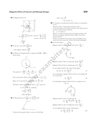
![From Eqs. (i), (ii) and (iii), we get
B B B
1 2 3
3
2
1
: : : :
= −
π π
π
= − −
π π π
2 2
3
4
1
2
: :
60 (d) We can consider the non-planar loop as made by two loops
ABCDA and AQRBA as shown in figure.
Magnetic field due to loop ABCDA will be along X-axis and
due to loop AQRBA along Z-axis. Magnitude of magnetic field
due to both loops will be equal.
Therefore, direction of resultant magnetic field at P will be
along
1
2
($ $)
i k
+ .
61 (a) Area vector, A CO OA
= ×
= − ° − ° ×
( cos $ sin $ ( $)
b b a
37 37
i k) j
= − × + ×
ab
5
4 3
[ ($ $) ( $ $)]
i j k j
Q cos and sin
37
4
5
37
3
5
° = ° =
= − −
ab
5
4 3
[ $ $]
k i
= −
ab
5
3 4
[ $ $]
i k
Magnetic moment, M A
= Ni0
= −
Ni ab
0
5
3 4
( $ $)
i k
B i
= B0
$
∴Torque, τ = × = − ×
M B i k i
Ni ab
B
0
0
5
3 4
( $ $) $
= × − ×
Ni abB
0 0
5
3 4
[ ($ $) ($ $)]
i i k i
= −
4
5
0 0
Ni abB $
j
62 (d) From the question, PQ r
= 2 sinα =
2 0
mv
Bq
sinα
Q θ π α
= −
( )
2 2
Here, α β
= andv v
= 0
∴ t
Bq m
= =
−
θ
ω
π α
2( )
( / )
=
−
2m
Bq
( )
π α
63 (b)
Deflecting torque due to current,
τ1
2
90
= ° =
( ) sin
niAB niL B
Restoring torque,
τ2 = force × perpendicular distance = ×
Mg
L
2
⇒ τ τ
1 2
≥
niL B Mg
L
2
2
≥ ⇒B
Mg
niL
≥
2
∴ B
Mg
niL
min =
2
Note M is along + Z-axis and B is along + X-axis. The magnetic
moment vector M tries to align along B through smaller angle to
have minimum potential energy, so coil rotates clockwise about
line BC.
64 (a) In the z = 0 plane, the situation is as follows
Here, P x y
( , ) is the point and r x y
= +
2 2
Magnetic field at P is perpendicular to OP, as it is shown in
figure.
So, B i j
= −
B B
sin $ cos $
θ θ
Here, B
I
r
=
µ
π
0
2
sin , cos
θ θ
= =
y
r
x
r
∴ B i j
= −
µ
π
0
2
I
r
y
r
x
r
$ $ =
−
+
µ
π
0
2 2
2
I y x
x y
( $ $)
( )
i j
330 OBJECTIVE Physics Vol. 2
P x, y
( )
B sin θ
θ
B cos θ
y
X
r
Y
x
O
θ
B
a
q
a
v0
P
v
Q
A B
C
D
Y
X
B
i
B2
B B B
= +
1
2
2
2
B1
D
C
A
B
Q
R
P a, , a
( 0 )
Z
X
^
k
^
i
^
j
Y](https://image.slidesharecdn.com/arihantneetobjectivephysicsvolume2bydcpandey2022edition-230417145135-9bce7664/85/Arihant_NEET_Objective_Physics_Volume_2_By_DC_Pandey_2022_Edition-pdf-341-320.jpg)
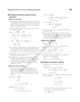
![B d I
( )
2 0
π µ
= ⇒ B
I
d
=
µ
π
0
2
⇒B
d
∝
1
where, µ0 = permeability of free space.
(ii) The magnetic field at surface, i.e. d R
= ,
B
I
R
=
µ
π
0
2
(iii) The current for a point inside the cylinder is given by
I′ = current per unit cross-sectional area of cylinder ×
cross-section of loop
= =
I
R
d
Id
R
π
π
2
2
2
2
∴Magnetic field at a point inside cylinder,
B
I
d
Id
R d
I
R
d
=
′
= =
µ
π
µ
π
µ
π
0 0
2
2
0
2
2 2 2
⇒ B d
∝
So, the variation of magnetic field can be plotted as
3 (a) The magnetic field within the turns of toroid, B
NI
r
=
µ
π
0
2
where, N = number of turns,
I = current in loops
and r = radius of each turn.
Given, N1 200
= , N2 100
= , r1 40
= cm, r2 20
= cm and current
I is same, i.e. I I I
1 2
= = , then
B
B
NI
r
r
N I
1
2
0 1
1
2
0 2
2
2
= ×
µ
π
π
µ
Substituting the given values in the above equation, we get
B
B
N
N
r
r
1
2
1
2
2
1
=
=
200
100
20
40
= × =
2
1
2
1
∴ B B
1 2 1 1
: :
=
4 (a) The magnetic field at the centre of an arc subtended at an
angle θ is given by
B
i
R
= ×
µ θ
π
0
2 2
Then, the magnetic field due to larger arc AB,
B
i
R
1
0 1
2
270
2
= ×
µ
π
…(i)
which acts in inward direction as per right hand thumb rule.
And magnetic field due to smaller arc AB,
B
i
R
2
0 2
2
90
2
= ×
µ
π
…(ii)
which acts in outward direction.
The resultant magnetic field, B B B
R = +
1 2
= −
×
+
×
µ
π
µ
π
0 1 0 2
270
4
90
4
i
R
i
R
…(iii)
[from Eqs. (i) and (ii)]
which acts in inward direction as B B
1 2
> .
Two arcs can also be seen as the two resistances in parallel
combination.
So, the potential across them will be same, i.e.
V V
1 2
=
iR i R
1 1 2 2
= …(iv)
where, R1 and R2 = resistance of respective segments.
The wire is uniform,
∴
R
R
L
L
R
R
1
2
1
2
270
90
= =
×
×
[Q length of arc = radius × angle]
⇒
R
R
1
2
3
= ⇒
R
R
2
1
1
3
= …(v)
From Eq. (iv), we get
⇒
i
i
R
R
1
2
2
1
1
3
= = or 3 1 2
i i
= …(vi)
From Eqs. (iii) and (v), we get
B
R
i i
R = − +
µ
π
0
1 2
4
270 90
( ) = − +
µ
π
0
1 1
4
270 90 3
R
i i
[ ( )]
= − + =
µ
π
0
1 1
4
270 270 0
R
i i
( )
5 (d) The centripetal force required for circular motion is
provided by magnetic force.
⇒
mv
r
Bqv
p
p
2
=
⇒ r
mv
qB
p
= … (i)
where,vp = perpendicular velocity of particle and q = charge
on particle.
As, momentum, p mvp
=
∴ r
p
qB
= [from Eq. (i)]
According to the question, moment a of both particles
are same.
⇒ r
q
∝
1
For ionised hydrogen atom, q e
H =
and for α-particle, q e
α = 2
⇒
r
r
q
q
e
e
H
H
α
α
= = =
2 2
1
or 2 1
:
332 OBJECTIVE Physics Vol. 2
i1
i2
i A
P
270°
B
90°
i
R
R
B
O d R
= d
B ∝ 1
d
B d
∝](https://image.slidesharecdn.com/arihantneetobjectivephysicsvolume2bydcpandey2022edition-230417145135-9bce7664/85/Arihant_NEET_Objective_Physics_Volume_2_By_DC_Pandey_2022_Edition-pdf-343-320.jpg)
![6 (d) When a charged particle of charge ( )
q is released from rest
( )
u = 0 in the uniform magnetic field ( )
B , then magnetic force
on the charged particle, F Bqu
= =
sinθ 0 because u = 0.
Therefore, the charge particle will not move in circular path.
In the magnetic field, force on charged particle always acts in
perpendicular direction to the direction of velocity of charged
particle, therefore, work done by magnetic field on charge
particle is zero. Hence, both Assertion and Reason are
incorrect.
7 (c) Given, radius of identical circular loops,
R = 10 cm = −
10 1
m
Current, I =
7
2
A
Distance from both circular loops at point P,
x x x
1 2 5
= = = cm = × −
5 10 2
m
From figure, according to Maxwell’s right hand thumb rule, it
is clear that magnetic field will be in same direction by both
the coils,
i.e. B B B
= +
1 2 =
+
+
+
µ µ
0
2
2 2 3 2
0
2
2 2 3 2
2 2
IR
R x
IR
R x
( ) ( )
/ /
=
+
µ0
2
2 2 3 2
I R
R x
( ) /
=
× ×
+
−
µ0
1 2
2 2 3 2
7 2 10
01 0 05
/ ( )
[( . ) ( . ) ] /
=
56
5
0
µ T
8 (a) Given, velocity of proton, v i
= 2$
Magnetic field, B i j k
= + +
($ $ $ )
3 4 µT
Electric field, E i
= 10$µ Vm−1
Applied Lorentz force on the proton,
F E v B
= + ×
q q( ) = + ×
q[ ( )]
E v B
= × × +
− −
16 10 10 10 2
19 6
. [ $ $
i i × + + × −
($ $ $ ) ]
i j k
3 4 10 6
= × × + −
− −
16 10 10 10 6 8
19 6
. [ $ $ $]
i k j
F i j k
= × − +
−
16 10 10 8 6
25
. [ $ $ $ ] N
∴ Acceleration of proton,
a
F
=
mp
(Qmp = × −
16 10 27
. kg)
=
× − +
×
−
−
16 10 10 8 6
16 10
25
27
. [ $ $ $ ]
.
i j k
a i j k
= − +
100 10 8 6
[ $ $ $ ]
∴ a = = + +
| |
a 100 10 8 6
2 2 2
= ×
100 1414
. = 1414 ms−2 ~
− 1400 ms−2
9 (a) When an electron enters into a uniform magnetic field in a
direction perpendicular to the direction of magnetic field,
then a magnetic force acts on the electron in perpendicular
direction of both direction of magnetic field and direction of
velocity of electron and direction of force can be determined
by Fleming’s left hand rule.
We know that, when direction of force on a particle is in
perpendicular direction to the direction of velocity, then
particle moves in uniform circular motion. Therefore, electron
moving perpendicular to magnetic field ( )
B will perform
circular motion.
Hence, both Assertion and Reason are correct and Reason is
the correct explanation of Assertion.
10 (a) Given, speed of proton,v = ×
45 105
. ms−1
Electrostatic force between two protons,
F k
e
r
e =
2
2
…(i)
Magnetic field produced due to moving proton of speed v,
B
ev
r
= ⋅
µ
π
0
2
4
…(ii)
∴Magnetic force on the proton,
F B ev
m = = ⋅ ⋅
µ
π
0
2
4
ev
r
ev [From Eq. (ii)]
F
e v
r
m = ⋅
µ
π
0
2 2
2
4
…(iii)
From Eqs. (i) and (iii), we get
F
F
ke
r
e v
r
e
m
=
⋅
2
2
0
2 2
2
4
µ
π
=
⋅
⋅
k
v
4
2
0
π
µ
F
F
e
m
=
× × ×
× × × −
9 10 4 314
45 10 4 10
9
5 2 7
.
( . ) π
= ×
44 105
.
11 (d) As, the system is in equilibrium,
∴ ΣFx = 0
According to the question,
mg F
sin cos
θ θ
= …(i)
where, F is the magnitude of force experienced by the rod
when placed in a magnetic field and current I is flowing
through it.
But the force experienced by the given rod in a uniform
magnetic field,
F ILB
=
∴ Eq. (i) becomes
mg ILB
sin cos
θ θ
=
⇒ I
mg
LB
=
sin
cos
θ
θ
=
mg
LB
tanθ
I
m
L
g
B
=
tanθ
…(ii)
Here,
m
L
= −
0.5 kg m ,
1
g = −
9.8 ms 2
, θ = °
30 ,
Magnetic Effect of Current and Moving Charges 333
q
m
g
sin
q
F
cos
q
B
q
F
mg](https://image.slidesharecdn.com/arihantneetobjectivephysicsvolume2bydcpandey2022edition-230417145135-9bce7664/85/Arihant_NEET_Objective_Physics_Volume_2_By_DC_Pandey_2022_Edition-pdf-344-320.jpg)
![B = 0.25 T
Substituting the given values in Eq. (ii), we get
I =
×
°
0.5 9.8
0.25
tan 30
0.5 9.8
0.25
1
3
=
×
× = 11.32 A
12 (a)Q B (at P) = −
µ
π
θ θ
0
1 2
4
I
d
(cos cos )
In given case, d R R
= ° =
sin /
45 2
θ1 135
= °, θ2 180
= °
∴ B (at P) =
µ
π )
0
4 2
I
R
( /
[cos cos ]
135 180
° − °
=
−
− −
µ
π
0
4
2
1
2
1
I
R
( )
=
−
µ
π
0
4
2
2 1
2
I
R
⇒ B P
I
R
( ) ( )
at = −
µ
π
0
4
2 1 T
13 (b) Here, dl dx
= = 1cm = −
10 2
m,
i = 10 A, r = 0 5
. m
∴ dB
i dl r
r
= ⋅
×
µ
π
0
3
4
( )
= ⋅ ×
µ
π
0
2
4
idl
r
($ $ )
i j
= ⋅
µ
π
0
2
4
idl
r
$
k
=
× ×
− −
10 10 10
0 5
7 2
2
( )
.
$
k = × −
4 10 8 $
kT
14 (a) Magnetic moment,
M NiA
=
where, N = number of turns in the current loop
and i = current.
Since, the orbiting electron behaves as a current loop of
current i, we can write
i
e
T
e
r v
ev
r
= = =
2 2
π π
/
where, A = area of the loop = πr2
⇒ M
ev
r
r
evr
=
=
(1)
2 2
2
π
π
( )
15 (a) The torque acting on a current carrying loop is given by
τ θ
= MB cos
= NiAB cosθ [ ]
QM NiA
=
where, N = number of turns,
i = current of loop,
A = area of loop
and B = magnetic field.
Thus, torque does not depend on shape of loop.
16 (a) According to Biot-Savart’s law, the magnetic induction at a
point to a current carrying element i l
δ is given
by
B
i l
r
= ⋅
µ
π
δ θ
0
2
4
sin
Directed normal to plane containing δl and r, θ being angle
between δl and r.
Field due to semicircular arc
Now, angle between a current element δl of semicircular arc
and the radius vector of the element to point c is π / 2.
Therefore, the magnitude of magnetic induction B at O due to
this element,
δ
µ
π
δ π / 2 µ δ
π
B
i l
r
i l
r
= ⋅ =
0
2
0
2
4 4
sin
Hence, magnetic induction due to whole semicircular loop is
B B
i l
r
= = ⋅
Σ Σ
δ
µ
π
δ
0
2
4
=
µ
π
δ
0
2
4
i
r
l
Σ = =
µ
π
π
µ
0
2
0
4 4
i
r
r
i
r
( )
The magnetic field due to ab and de is zero, because θ = °
0 or
180°, so net magnetic field is
B
i
r
=
µ0
4
17 (c) Magnetic field due to straight wire above O is zero,
i.e. B1 0
= (since, θ = °
0 )
The magnetic field due to semicircular part,
B
I
r
2
0
1
2 2
= × =
µ µ0
4
I
r
The magnetic field due to lower straight portion,
B
I
r
3
0
4
0 90
= °+ °
µ
π
(sin sin ) =
µ
π
0
4
I
r
(upward)
Net magnetic field,
B B B B
= + +
1 2 3 = +
0
4
0
µ I
r
+
µ
π
0
4
I
r
=
µ0
4
I
r
+
µ
π
0
4
I
r
(upwards)
18 (b) Magnetic field at the centre of the circular
loop of one turn, B
i
R
=
µ0
2
Now, the wire is bent into n circular coils.
Thus, new radius can be determined as
n r R
× =
2 2
π π
334 OBJECTIVE Physics Vol. 2
v
θ2
P
I
135°
I
I
45°
d
P
θ1
i
R](https://image.slidesharecdn.com/arihantneetobjectivephysicsvolume2bydcpandey2022edition-230417145135-9bce7664/85/Arihant_NEET_Objective_Physics_Volume_2_By_DC_Pandey_2022_Edition-pdf-345-320.jpg)
![⇒ r
R
n
=
∴Magnetic field at the centre of these loops,
B n
i
r
n
i
R
n
n
i
R
′ = =
=
µ µ µ
0 0 2 0
2
2
2
= n B
2
19 (a) The radius of a charged particle of mass m in a magnetic
field B is given by
r
mv
qB
= …(i)
where, q = charge on the particle.
and v = speed of the particle
∴ The time taken to complete the circle,
T
r
v
=
2π
⇒
T m
qB
2π
= [from Eq. (i)]
∴ ω
π
= =
2
T
qB
m
Q q e
= and
e
m
= 1.76×10¹¹
C/kg
B = × −
3.57 10 2
T
∴ ω =
eB
m
Now, frequency of revolution,
f
e
m
B
= = = × × × × −
ω
π π π
2
1
2
1
2
10 10
11 2
1.76 3.57
= ×
1.0 109
Hz = 1GHz
20 (d) The given figure is shown below
From this figure, it can be seen that the direction of currents
in the long straight conductor XY and arm AB of a square loop
ABCD are in the same direction. So, there exists a force of
attraction between the two which will be experienced by BA,
F
IiL
L
BA =
µ
π
0
2
2
In the case of XY and arm CD, the direction of currents are in
the opposite direction. So, there exists a force of repulsion
which will be experienced by CD. i.e.
F
IiL
L
CD =
µ
π
0
2
3
2
Therefore, net force on the loop ABCD,
F F F
IiL
L L
BA CD
loop = − = −
µ
π
0
2
1
2
1
3 2
( / ) ( / )
F
iI
loop =
2
3
0
µ
π
21 (b) Consider two Amperian loops of
radius
a
2
and 2a as shown in the figure.
Applying Ampere’s circuital law for
these loops, we get
B L =
∫ d I
µ0 enclosed
For the smaller loop,
⇒ B × = × ×
2
2 2
0 2
2
π µ
π
π
a I
a
a
= × =
µ
µ
0
0
1
4 4
I
I
⇒ B =
µ
π
0
4
I
a
at distance
a
2
from the axis of the wire.
Similarly, for bigger Amperian loop,
′ × =
B 2 2 0
π µ
( )
a I
(total current enclosed by Amperian loop is I)
⇒ ′ =
B
µ
π
0
4
I
a
at distance 2a from the axis of the wire.
So, ratio of
B
B′
= × =
µ
π
π
µ
0
0
4
4
1
I
a
a
I
22 (c) The magnetic fields in the different regions are given by
B
I
R
B
I
R
1
0
3
0
4 4
= × − = −
µ
π
µ
π
( $), ( $)
k k
and B
I
R
2
0
4
= −
µ
( $)
i
Net magnetic field at the centre O,
B B B B
I
R
I
R
I
R
= + + = − + − = − +
1 2 3
0 0 0
4
2
4 4
2
µ
π
µ µ
π
π
( $) ( $) ( $ $
k i k i)
23 (d) Current, I
q
t
=
So, for an electron revolving in a circular orbit of radius r,
q e
= and t T
=
⇒ I
e
T
e
= =
2π ω
/
= = =
ω
π
π
π
e ne
ne
2
2
2
The magnetic field produced at the centre,
B
I
R
ne
r
= =
µ µ
0 0
2 2
Magnetic Effect of Current and Moving Charges 335
A D
B C
X
Y
L
I
L
L/2
i
a/2
2a
R
I
I
I
Y
X
2
3
1
Z
O
X
B
I
e
r](https://image.slidesharecdn.com/arihantneetobjectivephysicsvolume2bydcpandey2022edition-230417145135-9bce7664/85/Arihant_NEET_Objective_Physics_Volume_2_By_DC_Pandey_2022_Edition-pdf-346-320.jpg)
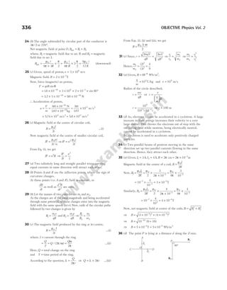
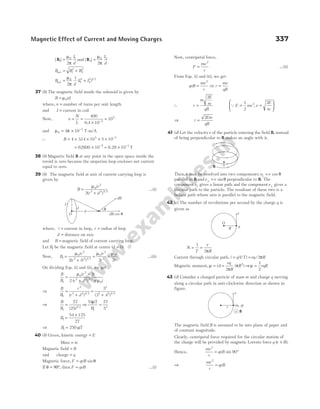
![⇒ Speed,v =
qBr
m
⇒ r
mv
qB
= …(i)
Let T be the time period of the periodic motion, i.e. time
taken to complete one revolution.
⇒ T
v r
r
v v
mv
qB
= = = =
2 2 2 2
π
ω
π π π
/
[from Eq. (i)]
=
2πm
qB
44 (b) Magnetic moment,
M = Current × Area of enclosed by loop
= ×
I A …(i)
Magnetic induction at the centre of circular loop,
B
I
R
=
µ0
2
⇒ I
BR
=
2
0
µ
…(ii)
Here, A R
= π 2
…(iii)
Substituting Eqs. (ii) and (iii) in Eq. (i), we get
M
BR
R
BR
= × =
2 2
0
2
3
0
µ
π
π
µ
45 (c) In cyclotron, force on charge = centripetal force
∴ qvB
mv
r
=
2
⇒r
mv
Bq
= ⇒r v
∝
46 (a) When a magnetic field is applied on a stationary electron,
then it remains stationary.
Because, F v B
= ×
q( )
If v = 0 ⇒ F = 0
47 (d) Given, r = = × −
0 05 0 05 10 9
. . ,
nm m (Q1 10 9
nm m
= −
)
n = 1016
rev/s, e = × −
16 10 19
. C
Magnetic moment, M Ai
=
M r ne
= ×
π 2
( )
QA r
= π 2
= × × × × ×
− −
3.14 (0.05 10 10 16 10
9 2 16 19
) .
or = × −
1.26 10 23
A-m2
48 (c) Given, radius of coil, r = = × −
10 10 10 2
cm m
Number of turns, N = 100 turns, current in coil, i = 1A
Magnetic moment, M = ?
Now, M NiA
= , where A r
= π 2
M Ni r
= = × × × × −
π 2 2 2
100 1 3142 10 10
. ( )
= × × × × =
−
100 1 3142 100 10 3142
4
. . A-m2
49 (c) The given situation is shown in the figure.
Since, given wires are very large, hence magnetic field due to
current in the first wire,
B
d
I
1
0
1
2
=
µ
π
The field is perpendicularly inward.
Now, force on the second wire due to first wire,
F l B
21 2 1
= ×
I ( ) (towards left)
F I lB
21 2 1 90
= °
sin
F I lB
21 2 1
=
where, l is the length of the wire and d is separation between
the two wires.
F I l
I
d
II l
d
21 2
0 1 0 1 2
2 2
=
=
µ
π
µ
π
According to question, | |
F21 = F
⇒ F
II l
d
=
µ
π
0 1 2
2
Now, consider the situation, when the current in first wire is
doubled and reversed, we can write
′ =
×
F
I I l
d
µ
π
0 1 2
2
2 3
( )( )
Here, force on second wire will be towards right.
So,
′
=
×
F
F
I I l
d
II l
d
µ
π
µ
π
0 1 2
0 1 2
2
2 3
2
( )( )
′
=
=
F
F
II
II
2
3
2
3
1 2
1 2
⇒ ′ = −
F
F
2
3
Here, negative sign is due to opposite directions of ′
F and F.
50 (a) From Fleming’s left-hand rule, when a particle is in motion
and magnetic field is perpendicular to the velocity.
51 (d) Angular momentum, L mvr
= …(i)
The orbital motion of electron is equivalent to a current.
∴ I e T
= ( / )
1
Period of revolution of electron, T
r
v
=
2π
∴ I e
r v
=
1
2π /
=
ev
r
2π
338 OBJECTIVE Physics Vol. 2
2I1 I2
3d
P
+q 90°
B
z
F
x
v
y
I1 I2
d](https://image.slidesharecdn.com/arihantneetobjectivephysicsvolume2bydcpandey2022edition-230417145135-9bce7664/85/Arihant_NEET_Objective_Physics_Volume_2_By_DC_Pandey_2022_Edition-pdf-349-320.jpg)
![Given,v = × −
2 103 1
ms
B = 1.5 T and θ = °
90
Hence, E vB
= = × × × °
sin sin
θ 2 10 90
3
1.5
= ×
3 103
V/m or N/C
64 (a) The magnetic field ( )
B at the centre of circular current
carrying coil of radius R and current
I B
I
R
, =
µ0
2
Similarly, if current = 2I, then
Magnetic field = =
µ0 2
2
2
I
R
B
So, resultant magnetic field
= +
B B
2 2
2
( )
= =
5 5
2
B B
=
µ0 5
2
I
R
65 (d) The given figure is shown below
Magnetic field outside the long rod,
B
i
r
=
µ
π
0
2
[for rod 3 and rod 4, r r
3 4
< ]
∴ B B
3 4 0
> ≠
66 (d) The magnetic field at the centre of new loop
B n B
′ = 2
where, n is the number of turns in the loop.
∴ B B
′ = ( )
4 2
or B B
′ = 16
67 (c) Under uniform magnetic field, force evB acts on proton and
provides the necessary centripetal force
mv
a
2
.
∴
mv
a
evB
2
= ⇒v
aeB
m
=
Now, angular momentum,
L r p a aeB a eB
= × = × = 2
68 (c) Given, B = × −
835 10 2
. $ ,
iT v = × ×
( $ $)
2 10 4 10
5 5
i + j m/s
The distance covered by proton, d T v
m
qB
v
= =
( ) ( )
2π
= × ×
×
× × ×
−
− −
2 314
167 10
16 10 835 10
27
19 2
.
.
. . $
i
× × ×
( $ $
2 10 4 10
5 5
i + j)
⇒ d = 0.157 m
69 (d) Given, n = 12 turns, I = 15A
, B = 0 2
. $,
i
A = − 0 04 2
. $
i m
∴ Potential energy,U nIAB
=
= × × − ×
12 15 0 04 0 2
( . ) . = −144
. J
70 (b) The described condition can be shown as
The magnetic field at P due to inner and outer conductors are
equal and opposite. Hence, the net magnetic field at P will be
zero.
71 (b) When the currents in the wires are in same direction.
Magnetic field at mid-point O due to I and II wires are
respectively
B
i
x
I = ⊗
µ
π
0 1
4
2
and B
i
x
II =
µ
π
0 2
4
2
. 8
So, the net magnetic field at O,
B
x
i i
net = ⋅ −
µ
π
0
1 2
4
2
( )
⇒ 10 10
4
2
6 0
1 2
× = ⋅ −
− µ
π x
i i
( ) …(i)
When the direction of i2 is reversed,
B
i
x
I = ⋅ ⊗
µ
π
0 1
4
2
and B
i
x
II = ⊗
µ
π
0 2
4
2
.
So, net magnetic field at O,
B
x
i i
net = ⋅ +
µ
π
0
1 2
4
2
( )
⇒ 40 10
4
2
6 0
1 2
× = ⋅ +
− µ
π x
i i
( ) …(ii)
On dividing Eq. (ii) by Eq. (i), we get
i i
i i
1 2
1 2
4
1
+
−
= ⇒
i
i
1
2
5
3
=
340 OBJECTIVE Physics Vol. 2
i1 i2
O
I II
x
x
i1 i2
O
x
x
I II
i
r
P
i
0 1 2 3 4](https://image.slidesharecdn.com/arihantneetobjectivephysicsvolume2bydcpandey2022edition-230417145135-9bce7664/85/Arihant_NEET_Objective_Physics_Volume_2_By_DC_Pandey_2022_Edition-pdf-351-320.jpg)

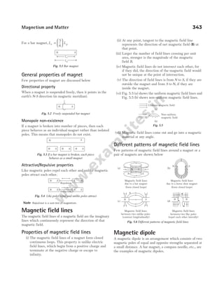
![Pole strength
Like electric charge, we have equivalent analogous in
magnetism which is known as pole strength. Thus, pole
strength can be defined as the strength of a magnetic
pole to attract magnetic materials towards itself. It is a
scalar quantity and its SI unit is ampere-metre (A-m). The
strength of N-pole and S-pole of a magnet is
conventionally represented by + m and − m, respectively.
It depends on the nature of material and area of
cross-section of the magnet.
Strength of N-pole and S-pole of a magnet is always equal
and opposite (+m and −m).
Magnetic dipole moment
It is the product of the strength of either of the pole
strength and the magnetic length of the magnet. It is
represented by M. It is a vector quantity.
The direction of magnetic dipole moment is same as that
of 2l. Therefore, M l
= m( )
2
Its SI unit is ampere-metre2
(A-m )
2
.
Pole strength and magnetic dipole moment in special cases
344 OBJECTIVE Physics Vol. 2
–m + m
S N
M
2l
Fig. 5.7 Bar magnet
Special cases Figure Effect on pole
strength
Formula for new
magnetic dipole moment
If bar magnet is cut into two
equal pieces such that the
length of each piece becomes
half
Remains unchanged M m
l M
′ = ⋅ =
2
2 2
(becomes half)
If bar magnet is cut into two
equal pieces such that the
width of each piece
becomes half
Pole strength of each
piece becomes half
M
m
l
M
′ =
=
2
2
2
( )
(becomes half)
If a bar magnet is bent in the
form of semi-circle
Remains unchanged M m r l r
′ = =
( )[ ]
2 2
Q π
M m
l M
′ = ×
=
2
2 2
π π
becomes times
2
π
When two identical bar
magnets are joined
perpendicular to each other
Remains unchanged M M M
= +
1
2
2
2
= 2M
When two bar magnets are
inclined at an angle θ
Remains unchanged Resultant magnetic moment,
M M M MM
′ = + +
1
2
2
2
1 2
2 cosθ
Angle made by resultant
magnetic moment ( )
M′ with M1
is given by
tan
sin
cos
φ
θ
θ
=
+
M
M M
2
1 2
+
+ +
–m m
2l
m –m m
l l
–m
S N
+
+
+
−m m
−m/2 m/2
m/2
2l
−m/2
S N
–m +m
N
2l
S
2r
+m
–m N
S
–m
+m
+m
–m
S N
N
S
θ
φ
S
(– )
m
N
(+ )
m
M1
S
(– )
m
N (+ )
m
M
M2](https://image.slidesharecdn.com/arihantneetobjectivephysicsvolume2bydcpandey2022edition-230417145135-9bce7664/85/Arihant_NEET_Objective_Physics_Volume_2_By_DC_Pandey_2022_Edition-pdf-355-320.jpg)
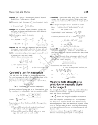
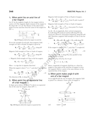
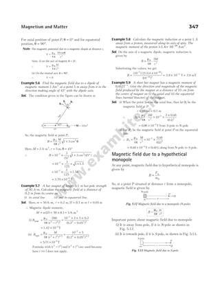
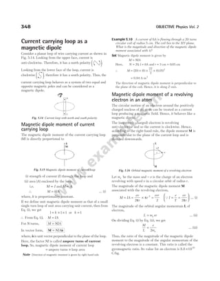
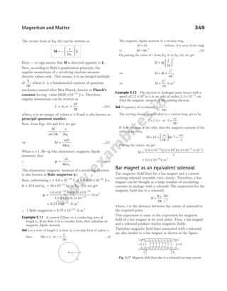
![Example 5.13 A closely wound solenoid of 800 turns and
area of cross-section 2.5 ×10⁴ 2
m carries a current of 3.0 A.
Explain the sense in which the solenoid acts like a bar
magnet. What is its associated magnetic moment?
Sol. It is given that, number of turns, N = 800
and area of cross-section, A = ×
2 5 104 2
. m
Now, magnetic moment of the solenoid,
M NIA
= = × × × −
800 3 0 2 5 10 4
. .
= −
0 60 1
. JT
which acts along the axis of the solenoid in the direction
related to the sense of flow of current according to right
handed screw rule.
Bar magnet in a uniform
magnetic field
When a bar magnet is placed in a uniform magnetic field,
torque acts on it. Also, magnetic potential energy is
associated with the magnet due to its orientation, which is
discussed in following sections.
Torque on bar magnet in a uniform magnetic field
Let us consider a bar magnet of length 2l placed in a
uniform magnetic field B. Let the magnetic axis of the bar
magnet makes angle θ with the field B, as shown in the
figure.
Then, force on N-pole = mB, along B
Force on S-pole = mB, opposite to B
where, m = strength of each pole
and B = strength of magnetic field.
These forces being equal and opposite form a couple, which
tends to rotate the magnet clockwise, so as to align it
along B. So, the moment of couple or torque is given by
τ = Force × Perpendicular distance
⇒ τ = ×
mB NA …(i)
In ∆NAS, sinθ =
NA
NS
=
NA
l
2
∴ NA l
= 2 sinθ
Eq. (i) becomes, τ θ
= ×
mB l
2 sin
Also, M m l
= × 2
⇒ τ θ
= MB sin …(ii)
In vector form, we can rewrite this equation as τ = ×
M B
The direction of τ is perpendicular to the plane containing
M and B and is given by right handed screw rule.
Work done or potential energy of a magnetic dipole
(bar magnet) in a magnetic field
The torque acting on the dipole tends to align it in the
direction of the field. Work has to be done in rotating the
dipole against the action of the magnetic torque. This work
done is stored in the form of potential energy of the dipole.
Now, a small amount of work done in rotating the dipole
through a small angle dθ is given by
dW d MB d
= τ = ⋅ θ
θ θ
sin [from Eq. (ii)]
Total work done in rotating the dipole from θ = θ0 to
θ θ
= can be obtained by integrating the above
expression.
∴ The potential energy of the dipole is given by
U W MB
= = − −
(cos cos )
θ θ0
Let us assume that, θ0 90
= °
So, U W MB
= = − − °
(cos cos )
θ 90
Therefore, U MB
= − cos θ
In vector notation, we may rewrite this equation as
U = − ⋅
M B
Special cases
(i) When dipole is perpendicular to magnetic field its
potential energy is zero, i.e. when θ = °
90
⇒ U MB MB
= − = − ° =
cos cos
θ 90 0
(ii) When the magnetic dipole is aligned along the
magnetic field, then it is in stable equilibrium having
minimum potential energy, i.e. when θ = °
0
⇒ U MB
= − cosθ = − ° = −
MB MB
cos0
(iii) When θ = °
180
U MB
= − cosθ
= − ° =
MB MB
cos180
In this condition, potential energy is maximum.
Example 5.14 A magnet of magnetic moment 50 2
$
iA m
- is
placed along the X-axis in a magnet field B i j
= +
( . $ $)
0 5 3 T.
Find the torque acting on the magnet.
Sol. Q Torque, τ = ×
M B
where, M is magnetic moment and B is magnetic field.
Given, M B
= = +
50 0 5 3
2
$ , . $ $
i i j
A m
- T
∴ τ = × +
50 0 5 3
$ ( . $ $)
i i j
τ = ×
150($ $
i j)
Using $ $ $ ,
i j k
× = we have
τ = 150 $
k N-m
350 OBJECTIVE Physics Vol. 2
mB
B
A
mB
S
N
N
θ
θ
2l
S
Fig. 5.18 Torque on a bar magnet](https://image.slidesharecdn.com/arihantneetobjectivephysicsvolume2bydcpandey2022edition-230417145135-9bce7664/85/Arihant_NEET_Objective_Physics_Volume_2_By_DC_Pandey_2022_Edition-pdf-361-320.jpg)
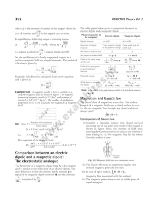
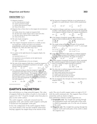
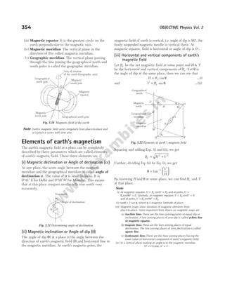
![So, angle of dip in vertical plane making an angle α with magnetic
meridian, tan
tan
cos
θ
θ
α
′ =
Example 5.21 A compass needle of magnetic moment
60 2
A m
- is pointing geographical north at a certain place.
It experiences a torque of 1.2 10 3
× −
N-m. The horizontal
component of earth’s magnetic field at that place is
40 µWb m
/ 2
. What is the angle of declination at that place?
Sol. A compass needle in stable equilibrium position points
towards magnetic north, i.e. along the horizontal component H
of earth’s magnetic field. When it is turned through the angle
of declination α, so as to point geographical north, then it
experiences a torque of magnitude MH sin α.
∴ MH sinα = × −
1.2 10 N-m
3
(given)
Here, M = 60 A-m ,
2
H = × /
−
40 10 Wb m
6 2
∴ sin α =
×
× ×
=
−
−
1.2 10
60 40 10
0.5
3
6
∴ α = °
30
Example 5.22 In the magnetic meridian of a certain place,
the horizontal component of earth’s magnetic field is 0.26 G
and the dip angle is 60°. Find
(i) vertical component of earth’s magnetic field
(ii) and the net magnetic field at this place.
Sol. Given, H = 0.26 G and θ = °
60
(i) As, tanθ =
V
H
∴ V H
= = ° =
tanθ (0.26) tan 60 0.45 G
(ii) As, H Be
= cos θ
∴ B
H
e = =
°
=
cos θ
0.26
cos 60
0.52 G
Example 5.23 The horizontal and vertical components of
earth’s field at a place are 0.22 G and 0.38 G, respectively.
Calculate the angle of dip and resultant intensity of earth’s
field.
Sol. Here, H = 0 22
. G andV = 0 38
. G
Now, tan
.
.
.
θ = = =
V
H
038
022
17272
∴ Angle of dip, θ = ° ′
59 56
Resultant magnetic field of the earth,
B H V
= + = + =
2 2 2 2
022 038 0 439
. . . G
Example 5.24 At a certain location in Africa, a compass
points 12° west of the geographic north. The north tip of the
magnetic needle of a dip circle placed in the plane of magnetic
meridian points 60° above the horizontal. The horizontal
component of the earth’s field is measured to be 0.16 G.
Specify the direction and magnitude of the earth’s field at the
location.
Sol. Using the relation, H Be
= cos θ, we get the magnitude of B
given by B
H
e = =
°
=
cosθ
0.16
cos 60
0.16
1
2
= × =
0.16 2 0.32 G
or B 0.32 10 T
4
= × −
[ ]
Q1 10 4
G T
= −
Direction of B The earth’s field lies in a vertical plane 12°
west of geographic meridian at an angle of 60° above the
horizontal line.
Example 5.25 A magnetic needle suspended in a vertical
plane at 30° from the magnetic meridian makes an angle of
45° with the horizontal. Find the true angle of dip.
Sol. In a vertical plane at 30° from the magnetic meridian, the
horizontal component,
H H
′ = °
cos 30
While vertical component is still V, therefore apparent dip
will be given by tan
cos
θ′ =
′
=
°
V
H
V
H 30
But
V
H
= ′
tan θ
∴ tan
tan
cos
θ
θ
′ =
°
30
(where, θ = true angle of dip)
∴ θ θ
= ′ °
−
tan [tan cos ]
1
30
= ° ° = ×
− −
tan [(tan ) (cos )] tan
1 1
45 30 1
3
2
≈ °
41
Example 5.26 A ship is to reach a place 10° south of west.
In which direction should it be steered, if the declination at
the place is 18° west of north?
Sol. As the ship has to reach a place 10° south of west, i.e.
along OP, so it should be steered west of magnetic north at
angle of 90 18 10 82
° − ° + ° = °.
Magnetism and Matter 355
Magnetic
meridian
30°
H¢
O
H
V
a
H
H′
V
q
B
MN GN
GW
MW
GS MS
GE
ME
18°
10°
P O](https://image.slidesharecdn.com/arihantneetobjectivephysicsvolume2bydcpandey2022edition-230417145135-9bce7664/85/Arihant_NEET_Objective_Physics_Volume_2_By_DC_Pandey_2022_Edition-pdf-366-320.jpg)
![Example 5.27 A dip circle shows an apparent dip of 45° at
a place where the true dip is 30°. If the dip circle is rotated
through 90°, what apparent dip will it show?
Sol. Let θ1 and θ2 are the angles of dip in two arbitary planes
which are perpendicular to each other.
Here, θ1 45
= ° and θ = °
30
As, cot cot cot
2 2
1
2
2
θ θ θ
= +
where, θ is true dip.
∴ cot cot cot
2 2 2
2
30 45
° = ° + θ
cot2
2 3 1 2
θ = − = ⇒ cotθ2 = 1.414
∴ θ2 = °
35.2
Example 5.28 A short magnet ( )
M A m
= × −
4 10 2
- 2
lying in
a horizontal plane with its north-pole points 37° east of north.
Find the net horizontal field at a point 0.1m away from the
magnet (Here, Bh = 11µ T) (sin / , cos / ).
37 3 5 37 4 5
° = ° =
Sol.
Magnetic field due to magnet at P,
B
M
r
1
0
3
4
2
= ⋅
µ
π
θ
cos
=
× × × ×
= ×
− −
−
10 2 4 10
4
5 6 4 10
7 2
3
6
( )
.
0.1
T
B
M
r
2
0
3
4
= ⋅
µ
π
θ
sin
=
× × ×
= ×
− −
−
10 4 10
3
5 10
7 2
3
6
( )
0.1
2.4 T
Since, B1 and Bh are in same direction,
∴ B B Bh
′ = + = × + ×
− −
1
6 6
6 4 10 11 10
.
= × −
174 10 6
. T
∴ B B B
P = ′ + = + × −
2
2
2 2 2 6
10
( (
17.4) 2.4)
= × −
308.52 T
10 6
= × −
17 5 10 6
. T
and tan .
β =
′
=
×
×
=
−
−
B
B
2
6
6
10
5 10
014
2.4
17.
Example 5.29 The earth’s magnetic field at geomagnetic
poles has a magnitude 8 10 5
× −
T. Find the magnitude and
the direction of the field at a point on the earth’s surface
where the radius makes an angle of 120° with the axis of
the earth’s assumed magnetic dipole. What is the inclination
(dip) at this point?
Sol.
The geomagnetic poles are in end-on-position.
The magnetic field at geomagnetic poles,
B
M
R
′ = ⋅ = × −
µ
π
0
3
5
4
2
8 10 T (given)
The magnetic field at point P,
B
M
R
P = +
µ
π
θ
0
3
2 1 2
4
1 3
( cos ) /
=
′
+
B
2
1 3 2 1 2
( cos ) /
θ
=
×
+ °
−
8 10
2
1 3 120
5
2 1 2
[ cos ] /
= × +
−
4 10 1
3
4
5
1
2
Hence, tan tan tan
α θ
= = °
1
2
1
2
120
= × − = −
1
2
3
3
2
( )
α = −
−
tan 1 3
2
Dip φ is an angle made by the earth’s magnetic field with the
horizontal plane,
φ α
= − ° = −
− °
−
90
3
2
90
1
tan
Neutral points
When we trace magnetic lines of force around a magnet
using a compass needle, we obtain the resultant of the
magnetic field of magnet and that of the earth. In the plot
of the resultant magnetic field, we come across points at
which field ( )
B due to the magnet becomes equal and
opposite to the horizontal component ( )
H of the earth’s
field, i.e. B H
= . Therefore, the net magnetic field at these
points will be zero.
356 OBJECTIVE Physics Vol. 2
θ
S
N
O
B2
B1
P Bh
S
N
M cos θ
1
2
M sin θ
r
β
B2
Bp
B′
P
S
N
North
P
R
θ=120°
South
α
R
BP
Vertical](https://image.slidesharecdn.com/arihantneetobjectivephysicsvolume2bydcpandey2022edition-230417145135-9bce7664/85/Arihant_NEET_Objective_Physics_Volume_2_By_DC_Pandey_2022_Edition-pdf-367-320.jpg)
![The magnet will be deflected through an angle θ, such that
the two couples balance each other and the tangent of the
angle of deflection gives the ratio of the two fields as
tan θ =
B
B
1
2
where, θ is angle between magnet and magnetic field B2.
In case of tangent galvanometer, a magnetic compass needle
is placed horizontally at the centre of a vertically fixed
current- carrying coil whose plane is in the magnetic
meridian.
As shown in figure, pointer P is rigidly attached to
compass needle and perpendicular to it. The compass
needle together with pointer can rotate freely about the
vertical axis.
When no current flows through the coil, its plane is
parallel to compass needle and coincides with magnetic
meridian. When current passes through the coil, it
produces magnetic field at the centre which deflects the
compass needle and pointer deflects through the same angle.
The magnetic field produced at centre due to a coil,
B
NI
r
c =
µ0
2
where, N is number of turns in the coil, r is radius of coil
and I is current in the coil.
Field Bc is perpendicular to the plane of coil, i.e.
perpendicular to magnetic meridian
or perpendicular to the horizontal component of earth’s
magnetic field.
The resultant horizontal magnetic field,
B B H
c
= +
2 2
⇒ tan θ =
B
H
c
(tangent law of perpendicular field)
The needle will stay in equilibrium when its length is
parallel to B.
The deflection of the needle from its original position θ is
given by
H B
NI
r
c
tan θ
µ
= = 0
2
⇒ I
rH
N
=
2
0
µ
θ
tan = k tan θ …(i)
where, k
rH
N
=
2
0
µ
is constant for a given galvanometer at
given place and is called reduction factor of galvanometer.
Sensitivity
Sensitivity is the measure of change in the deflection
produced by a unit current.
It is given by
d
dI k
k
I
k
θ
θ
= =
+
1 1
1
2 2
2
sec
[using Eq. (i) and sec tan
2 2
1
θ θ
= + ]
For good sensitivity, the change in deflection should be
large for a given fractional change of current.
Note The tangent galvanometer is most sensitive when deflection is
around 45°.
Example 5.32 In a tangent galvanometer, when a current of
10 mA is passed, the deflection is 31°. By what percentage,
the current has to be increased, so as to produce a deflection
of 42°?
Sol. Here, I1 10
= mA, θ1 31
= °, I2 = ?, θ2 42
= °
As,
I
I
2
1
2
1
=
tan
tan
θ
θ
∴ I I
2 1
2
1
10
42
31
= = ×
°
°
tan
tan
tan
tan
θ
θ
=
×
=
10 0 9
0 6
15
.
.
mA
Percentage increase in current,
( ) ( )
%
I I
I
2 1
1
100
15 10
10
100 50
−
× =
−
× =
Example 5.33 The coil of a tangent galvanometer of radius
12 cm is having 200 turns. If the horizontal component of
earth’s magnetic field is 25 µT, find the current which gives
a deflection of 60°.
Sol. Given, r = radius of coil = 12 cm = 0.12 m,
N = number of turns of coil = 200,
H = = × −
25 25 10 6
µT T and φ = °
60
As we know,I k
= tanθ
where, k
rH
N
=
2
0
µ
∴ I
rH
N
=
2
0
µ
θ
tan =
× × × × °
× ×
−
−
2 25 10 60
4 10 200
6
7
0.12 tan
π
= 0.042 A
358 OBJECTIVE Physics Vol. 2
P A C
S
T1
T2
B
H
Bc
θ
Fig. 5.26 Tangent galvanometer](https://image.slidesharecdn.com/arihantneetobjectivephysicsvolume2bydcpandey2022edition-230417145135-9bce7664/85/Arihant_NEET_Objective_Physics_Volume_2_By_DC_Pandey_2022_Edition-pdf-369-320.jpg)
![and θ = angle of dip
Then, H B
1 1 1
= cos θ and H B
2 2 2
= cos θ
Further, T
I
MH
1
1
2
= π = 2
1 1
π
θ
T
MB cos
and T
I
MH
2
2
2
= π = 2
2 2
π
θ
I
MB cos
Q
T
T
B
B
1
2
2
2
2 2
1 1
=
cos
cos
θ
θ
∴ cos cos
θ θ
2
1
2
1
2
2
2 1
= ×
B
B
T
T
= ×
B
B
1
2
2
1
2
1
ν
ν
θ
cos
=
°
0.5
0.6
20
15
cos 60
2
= 0.74
∴ θ2
1
cos (0.74) 42.2
= = °
−
Example 5.38 A small bar magnet having a magnetic
moment of 9 10 9 2
× −
A m
- is suspended at its centre of
gravity by a light torsionless string at a distance of 10 2
−
m
vertically above a long, straight horizontal wire carrying a
current of 1.0 A from east to west. Find the frequency of
oscillation of the magnet about its equilibrium position. The
moment of inertia of the magnet is 6 10 9 2
× −
kg m
- .
( 3 10 )
5
Take, H T
= × −
Sol. The magnetic moment of the bar magnet,
M 9 10 9
= × −
A-m2
The magnitude of the magnetic field at the location of the
magnet due to current carrying wire is,
B
i
r
= =
× −
−
µ
π
0
2
(2 10 ) (1.0)
10
7
2
2 10 Wb m
= × /
−5 2
(S to N)
The earth’s horizontal magnetic field,
H = × −
3 10 T
5
= × /
−
3 10 Wb m
5 2
∴ B H
+ = × /
−
5 10 Wb m
5 2
The frequency of oscillation will be
ν
π
=
+
1
2
M B H
I
( )
[here, I = moment of inertia]
=
× × ×
×
− −
−
1
2
9 10 5 10
6 10
9 5
9
π
( ) ( )
[ ]
S N
to
= × −
1.38 10 Hz
3
Example 5.39 A thin rectangular magnet suspended freely
has a period of oscillation equal to T. Now, it is broken into
two equal halves (each having half of the original length)
and one piece is made to oscillate freely in the same field. If
its period of oscillation is T′, then find the ratio T T
′/ .
Sol. When magnet is divided into two equal parts, the magnetic
dipole moment,
M′ = pole strength × =
l M
2 2
[pole strength remain same]
Also, the mass of magnet becomes half, i.e. m
m
′ =
2
.
Moment of inertia of magnet, I
ml
=
2
12
.
New moment of inertia, I
m l ml
′ =
=
×
1
12 2 2 12 8
2 2
⇒ I
I
′ =
8
Now, T
I
MB
=
2π
and T
I
M B
I
MB
′ =
′
′
=
2 2
8
2
π π
/
/
T
T T
T
′ = ⇒
′
=
2
1
2
Example 5.40 The time period of the magnet in an
oscillation magnetometer in the earth’s magnetic field is 2 s.
A short bar magnet is placed to the north of the
magnetometer, at a separation 10 cm from the oscillating
magnet, with its north pole pointing towards north. The time
period becomes half. Calculate the magnetic moment of this
short magnet.
(Take, B T
h = 12µ )
Sol. Time period, T
I
MB
= 2π
⇒ T
B
B
T
∝ ⇒ ∝
1 1
2
Let M is magnetic moment and B ′ is the magnetic field due to
short magnet, along south to north.
Given, T1 2
= s, Bh = 12 µT
T B B B B
h
2 1 12
= = + ′ = + ′
s,
( )
B B
B
T
T
+ ′
= 1
2
2
2
12
12
2
1
4
2
+ ′
=
=
B
⇒ B′ = 36 µT
B
M
r
′ =
µ
π
0
3
4
2
⇒ 36 10 10
2
6 7
3
× = ×
− − M
( )
0.10
M = 0.18 A-m2
Magnetism and Matter 361
Short
magnet
N
S
10cm](https://image.slidesharecdn.com/arihantneetobjectivephysicsvolume2bydcpandey2022edition-230417145135-9bce7664/85/Arihant_NEET_Objective_Physics_Volume_2_By_DC_Pandey_2022_Edition-pdf-372-320.jpg)
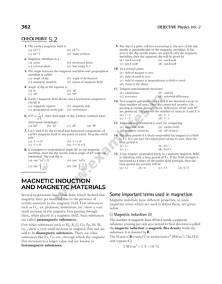
![(ii) Intensity of magnetisation ()
I
It is defined as the magnetic moment per unit volume of
the magnetised substance. This basically represents the
extent to which the substance is magnetised.
Thus, I =
M
V
The SI unit of I is ampere/metre (A/m). Its dimensional
formula is [M L T A
0 0
−1
].
Note For bar magnet, I m A
= / .
(iii) Magnetic intensity or Magnetic
field strength ( )
H
The capability of the magnetising field to magnetise the
substance is expressed by means of a vector H, called the
magnetic intensity of the field. It is defined through the
vector relation,
H
B
I
= −
µ0
The SI unit of H is same as that of I, i.e. ampere/metre
(A/m). The CGS unit is oersted.
Note
(i) In vacuum, I = 0∴H =
B
µ 0
.
(ii) The magnetic field intensity of solenoid is H n
= I. It is independent
of the material of the core of a solenoid.
(iii) When magnetic material is kept inside the solenoid, then
B B B
= +
0 M
where, B0 = magnetic field due to magnetising field
and Bm = magnetic field due to magnetisation of the material.
(iv) Magnetic permeability ( )
µ
It is defined as the ratio of the magnetic induction B inside
the magnetised substance to the magnetic intensity H of
the magnetising field.
i.e. µ =
B
H
It is basically a measure of conduction of magnetic lines of
force through a substance. The SI unit of magnetic
permeability is weber/ampere-metre (Wb/A-m) or tesla
metre-ampere−1
(TmA−1
).
(v) Relative magnetic permeability (µr)
It is the ratio of the magnetic permeability µ of the
substance to the permeability of free space.
Thus, µ
µ
µ
r =
0
µr is a pure ratio, hence dimensionless. For vacuum, its
value is 1.
µr can also be defined as the ratio of the magnetic field B
in the s](https://image.slidesharecdn.com/arihantneetobjectivephysicsvolume2bydcpandey2022edition-230417145135-9bce7664/85/Arihant_NEET_Objective_Physics_Volume_2_By_DC_Pandey_2022_Edition-pdf-374-320.jpg)
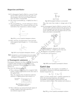
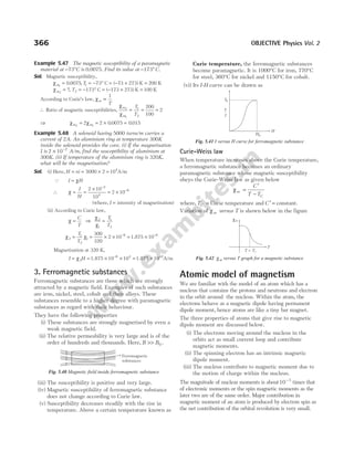
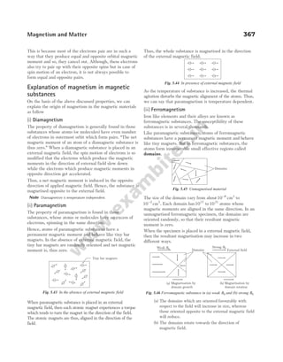
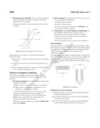
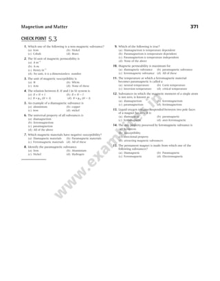

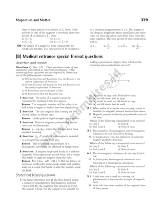
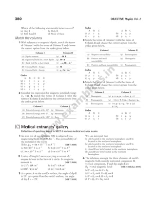
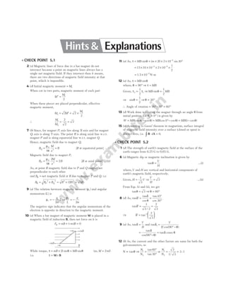
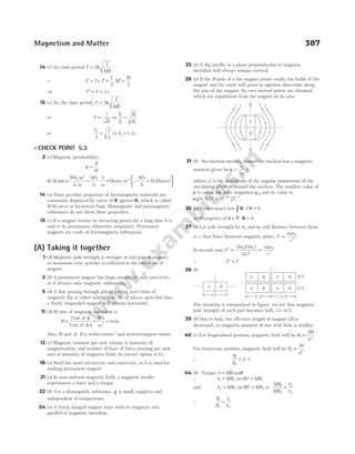
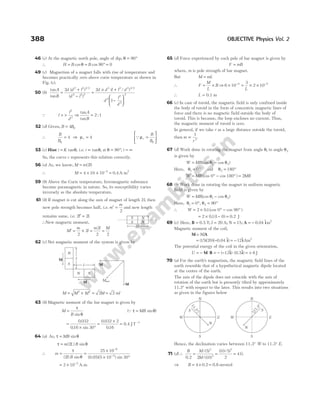
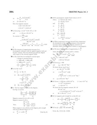
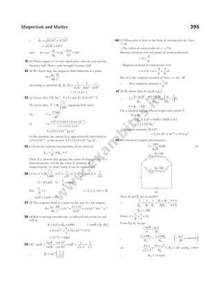
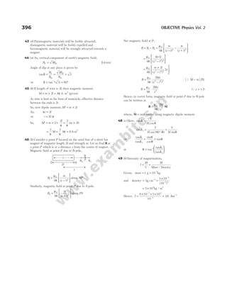
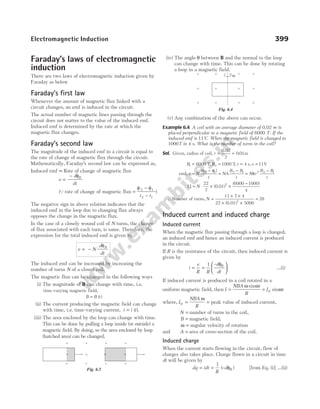
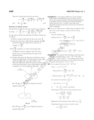
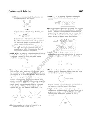
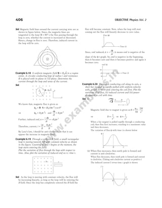
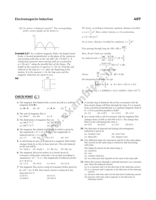
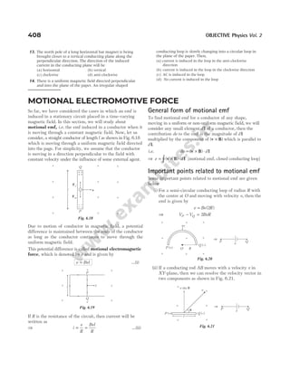
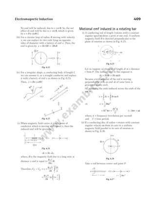
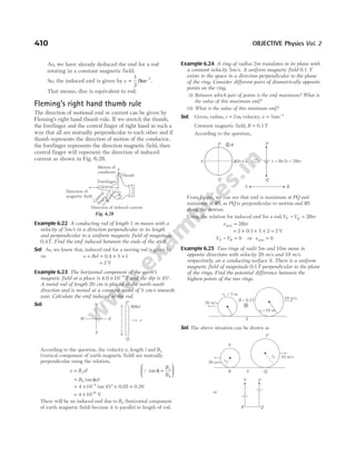
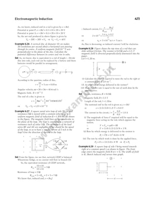
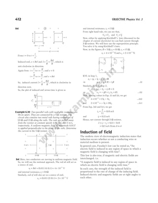
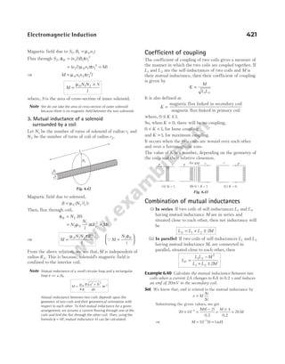
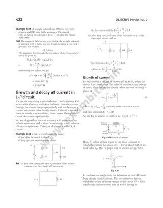
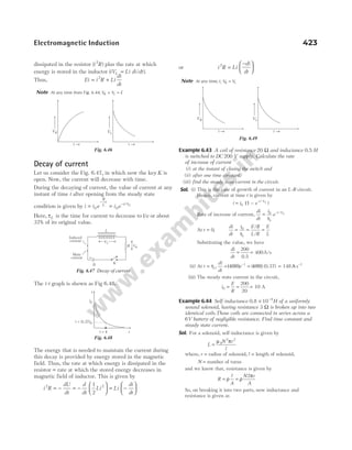
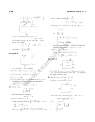
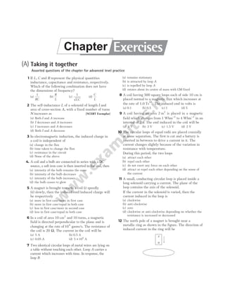
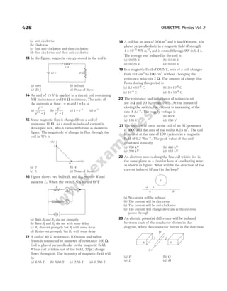
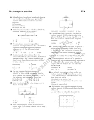
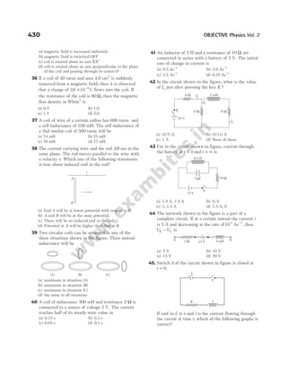
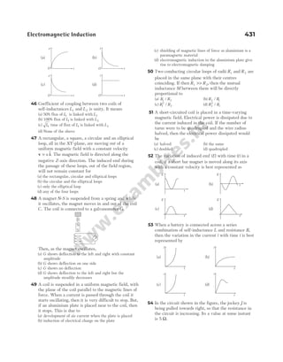
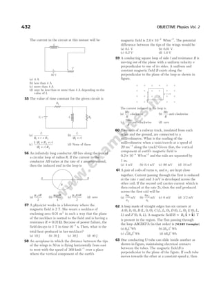
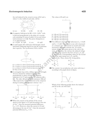
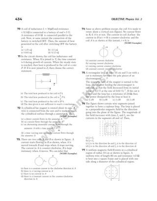
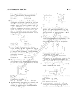
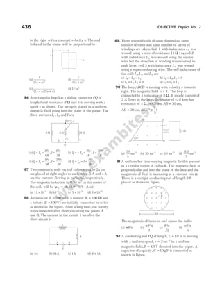
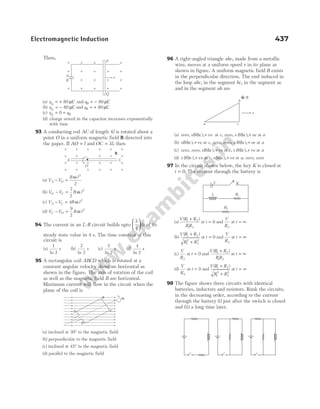
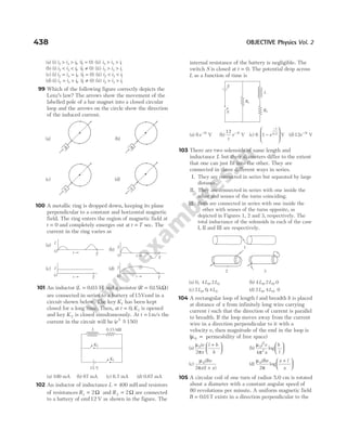
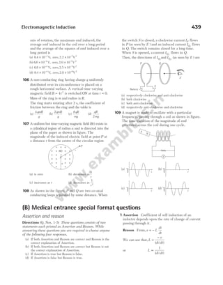
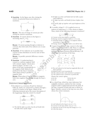
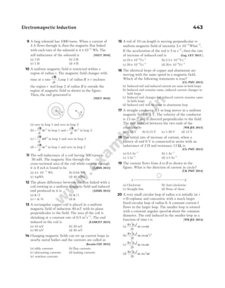
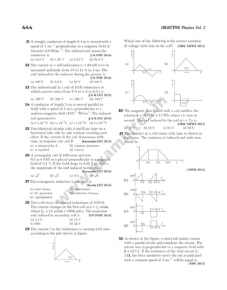


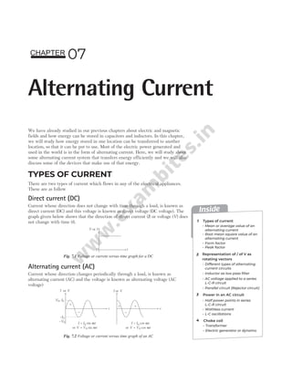
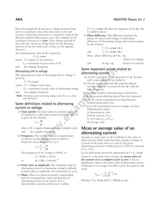
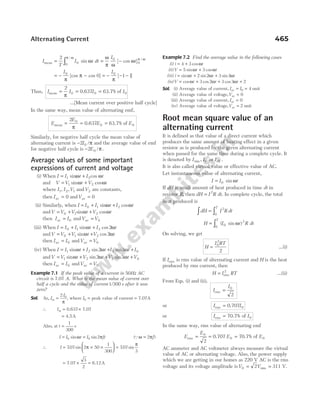
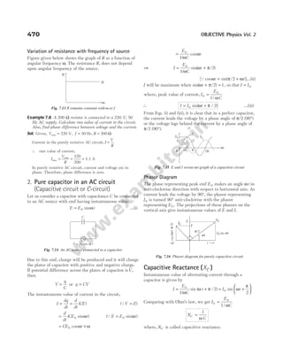
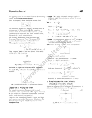
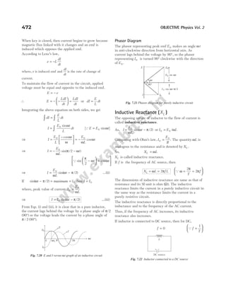
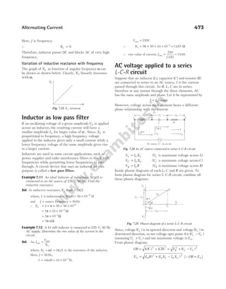
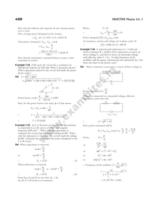
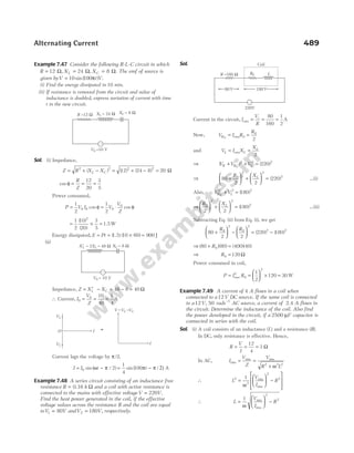
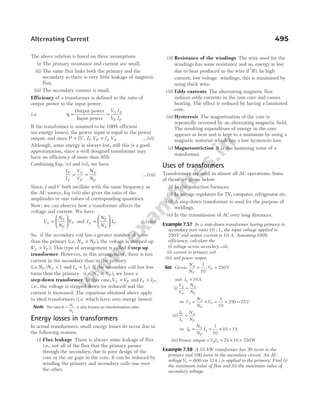
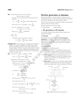
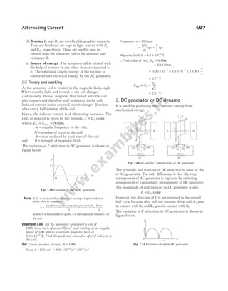
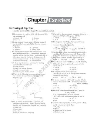
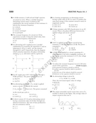
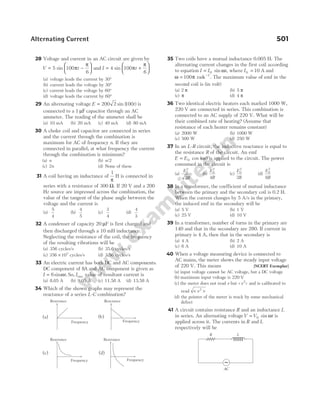
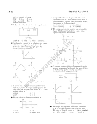
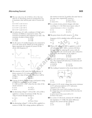
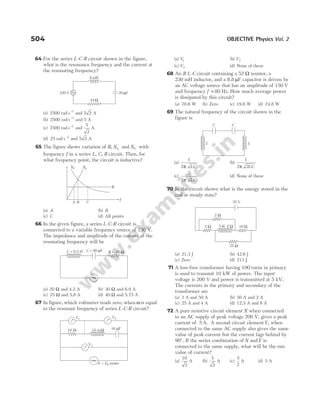
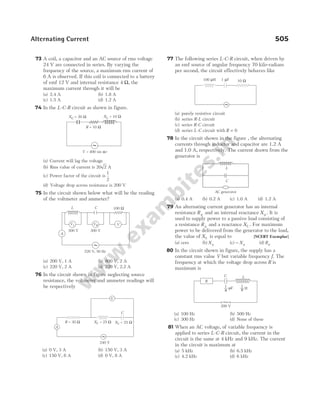
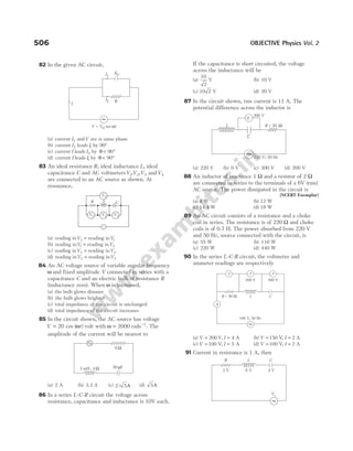
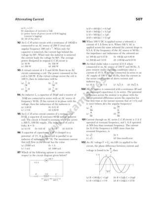
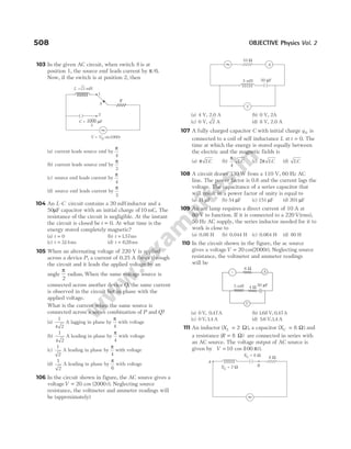
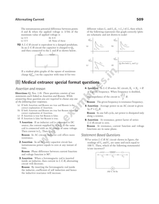
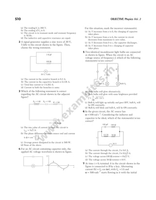
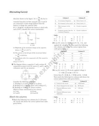
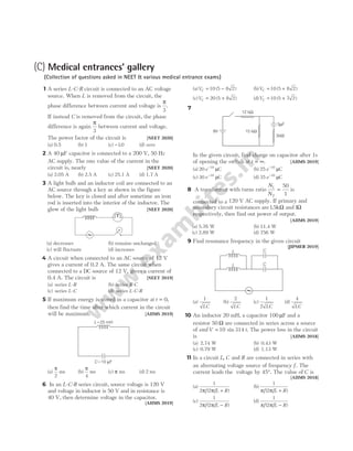
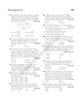
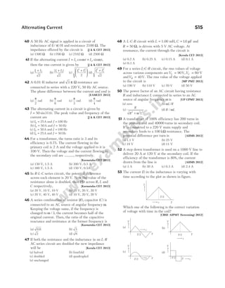
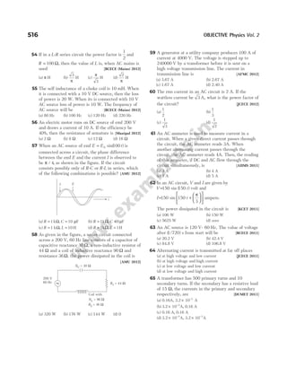
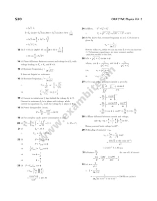
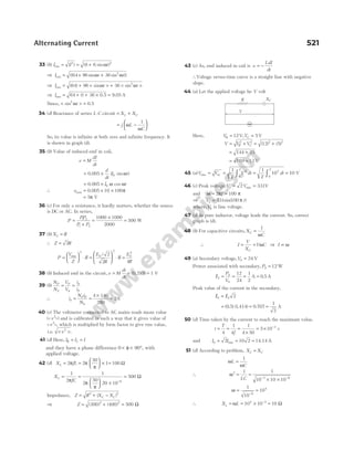
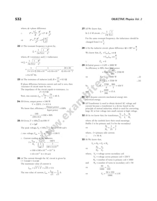
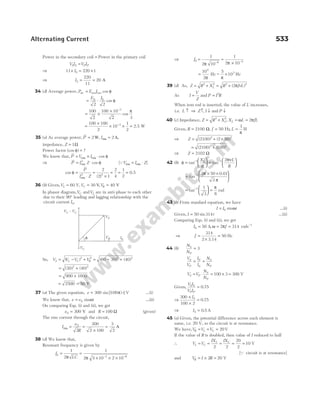
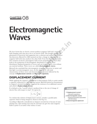
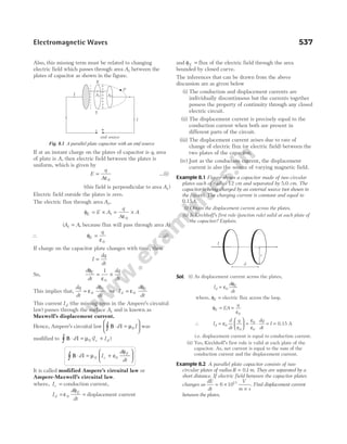
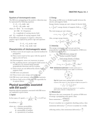
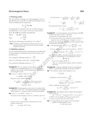
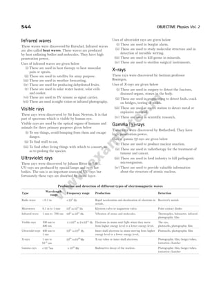
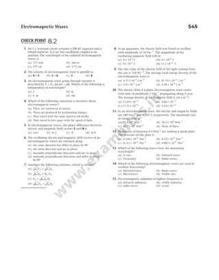
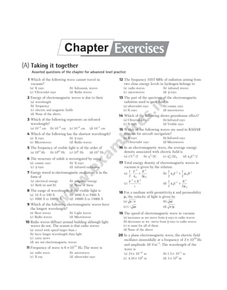
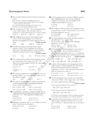
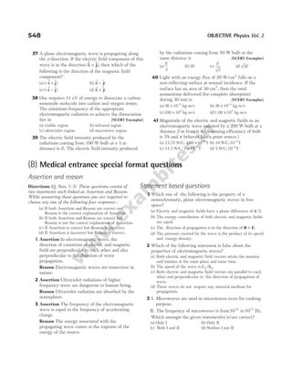
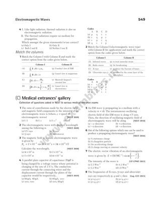
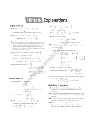
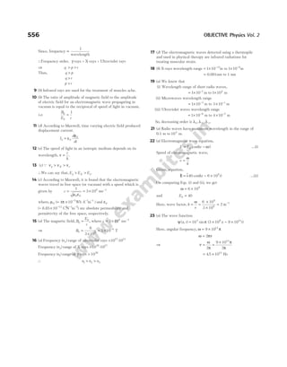
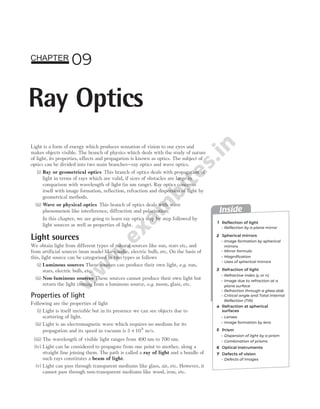
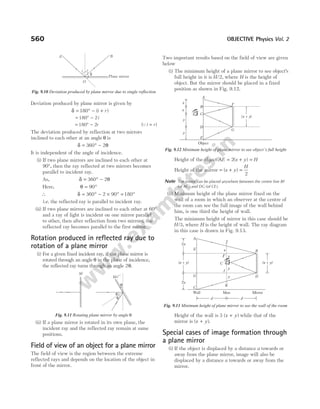
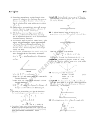
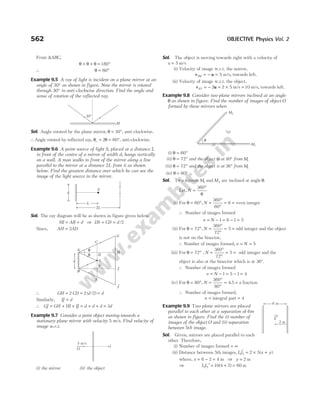
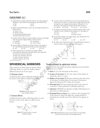
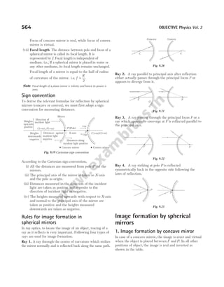
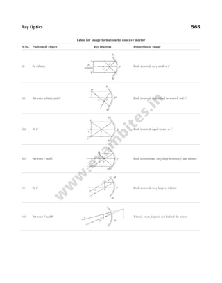
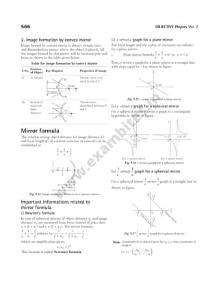
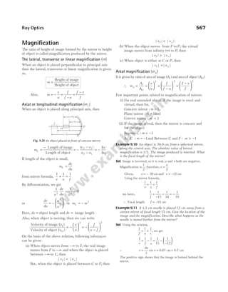
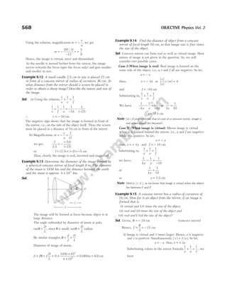
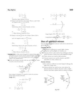
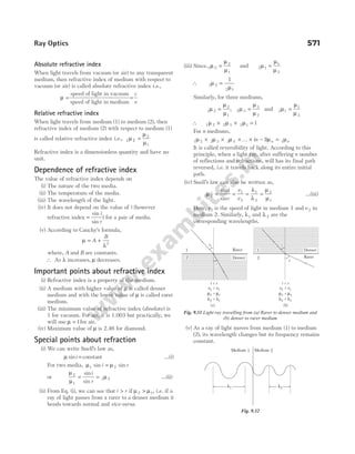
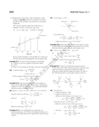
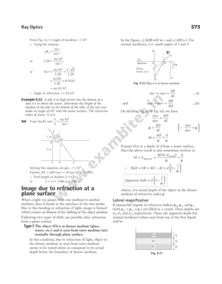
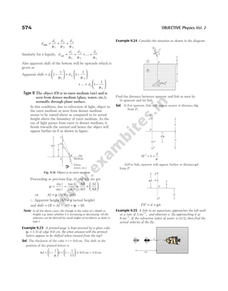
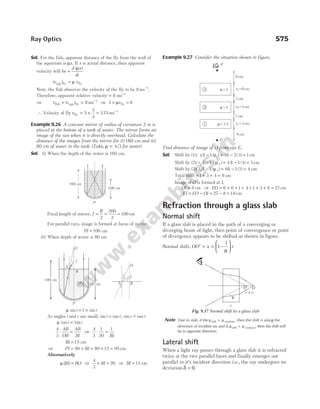
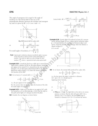
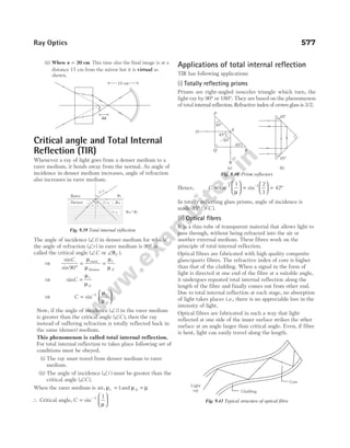
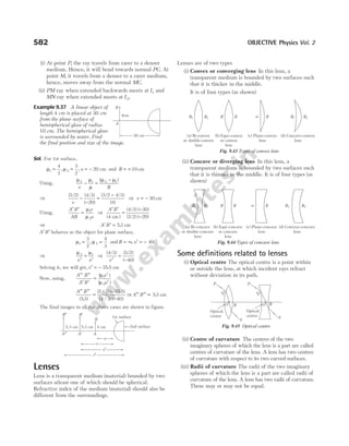
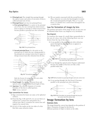
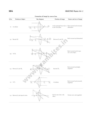
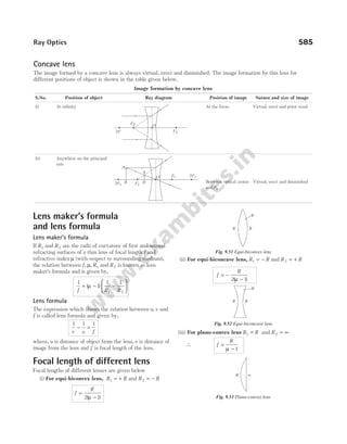
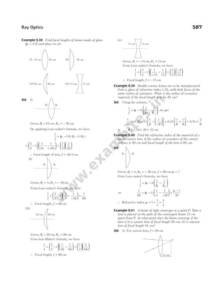
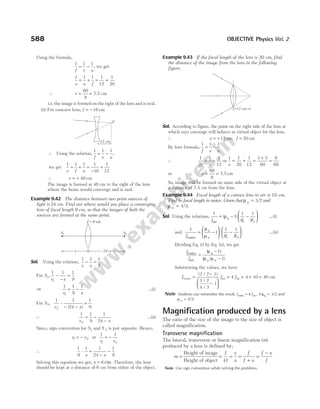
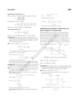
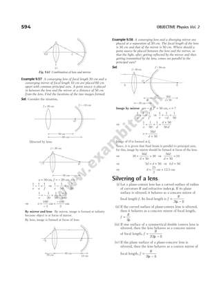
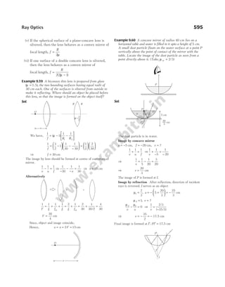
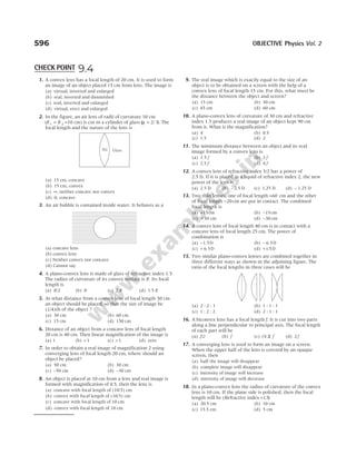
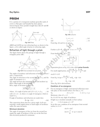
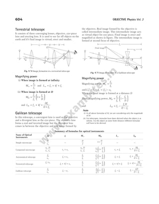
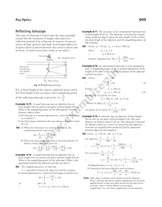
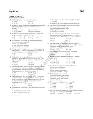
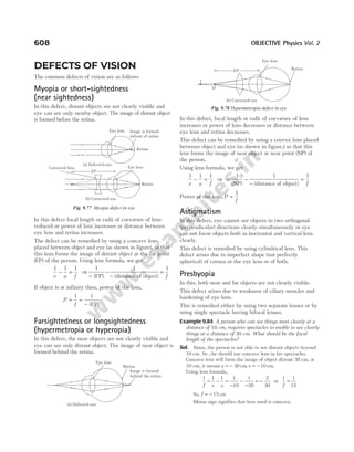
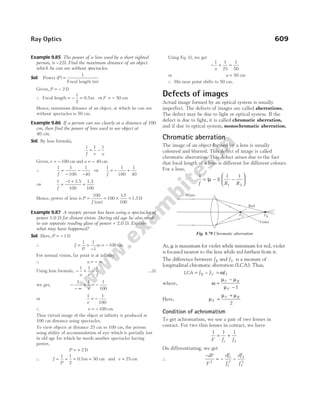
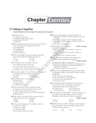
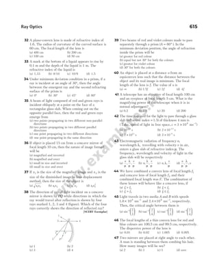
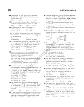
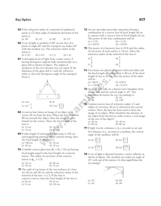
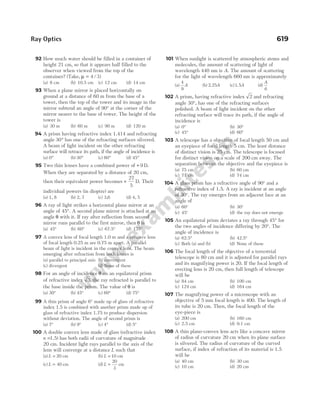
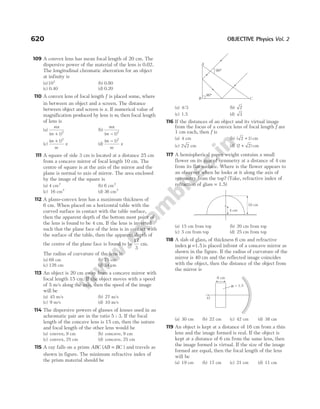
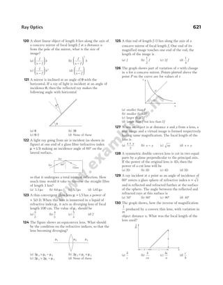
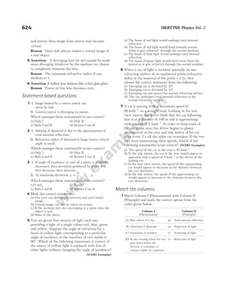
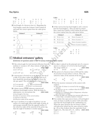
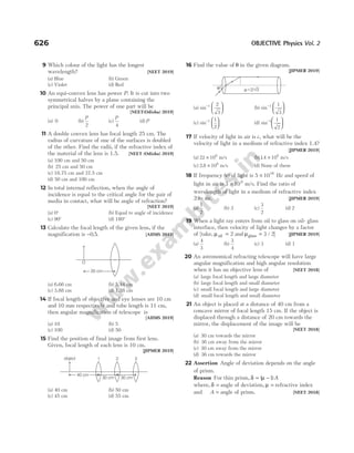
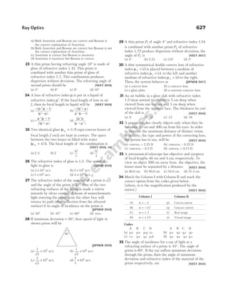
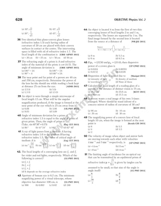
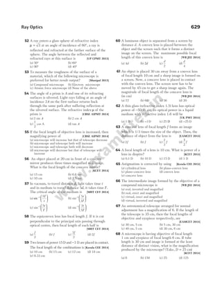

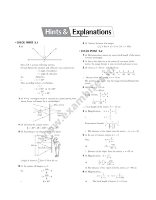
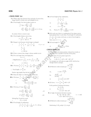
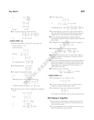
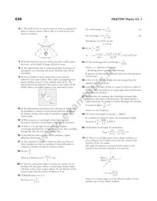
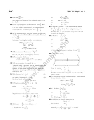
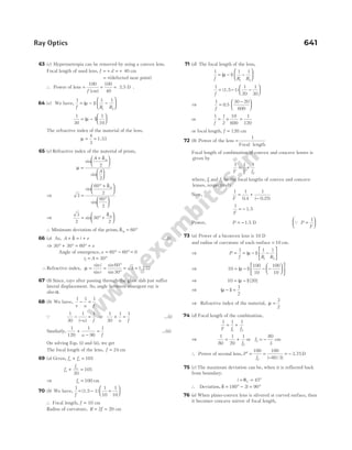
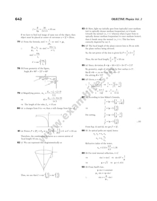
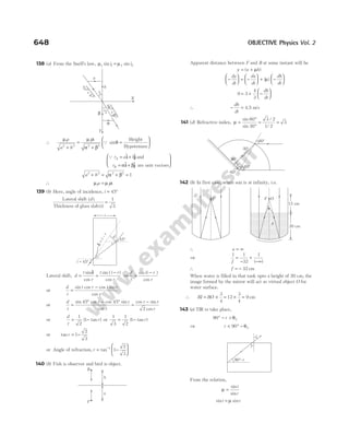
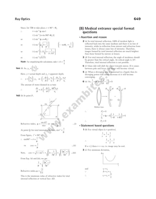
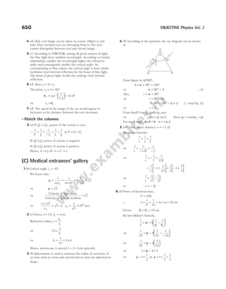
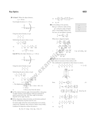
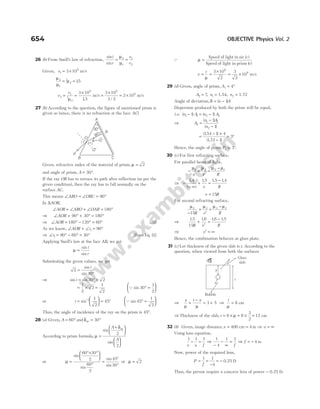
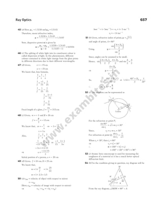
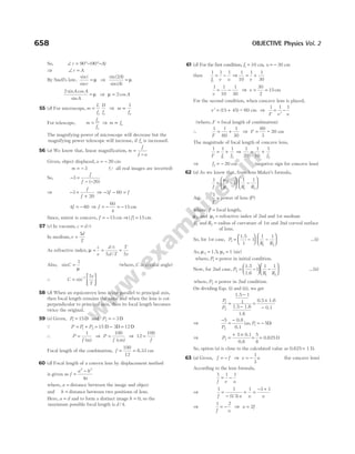
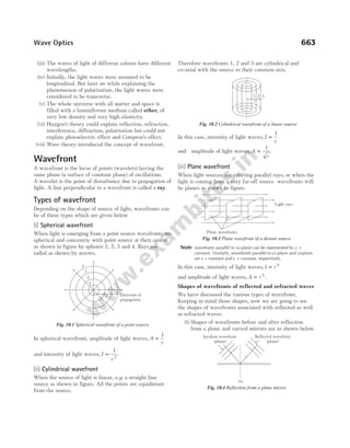
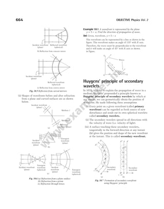
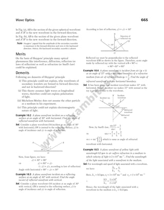
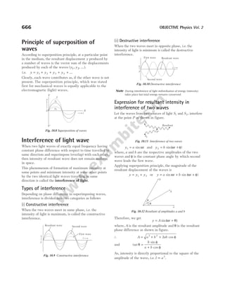
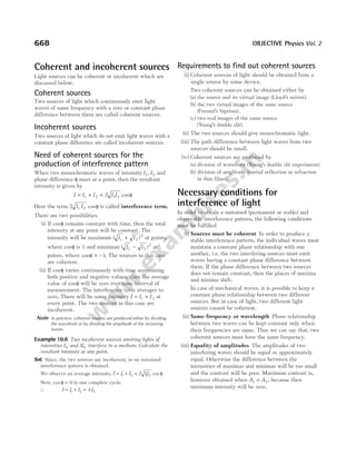
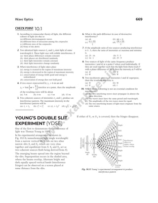
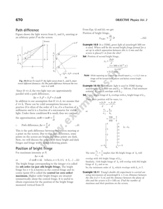
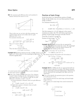
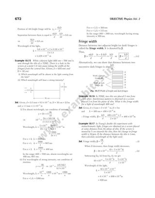
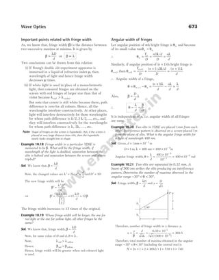
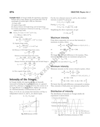
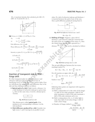
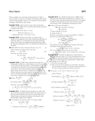
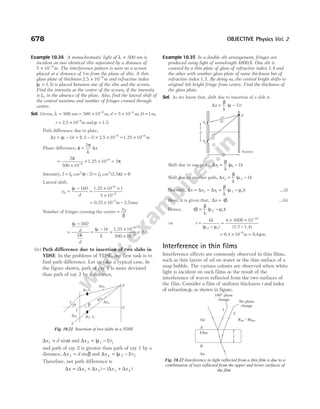
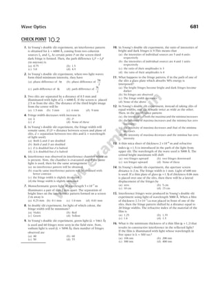
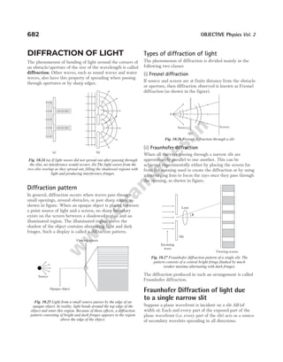
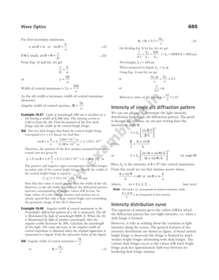
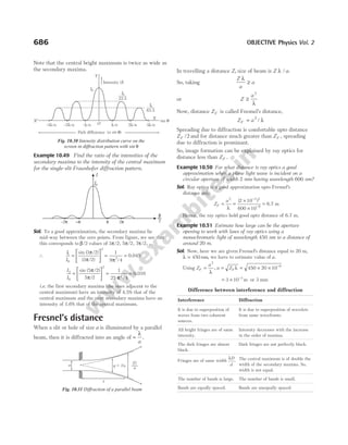
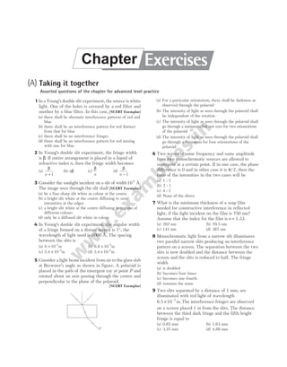
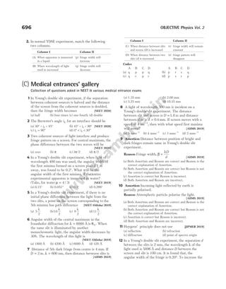
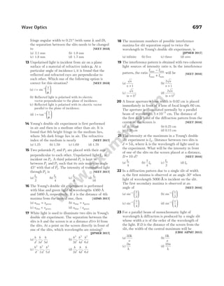
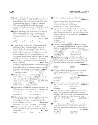
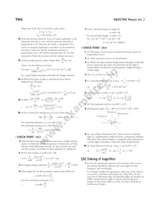
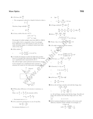
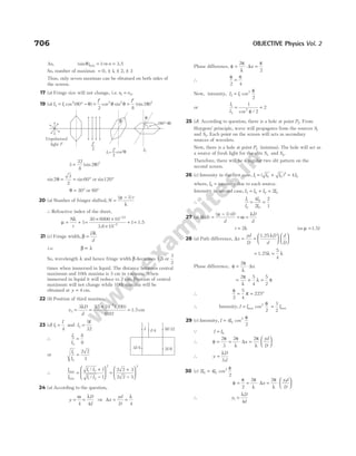
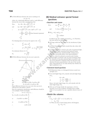
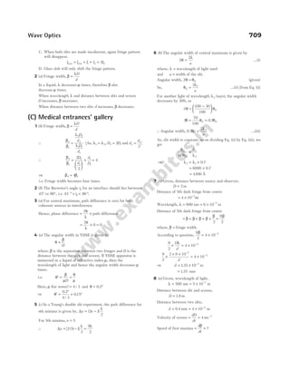
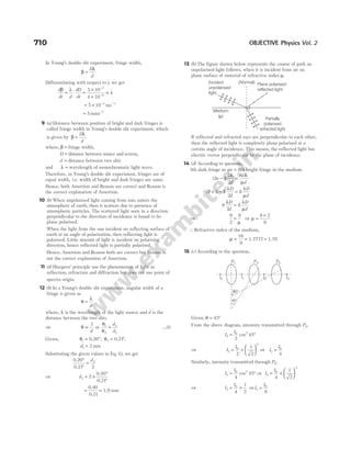
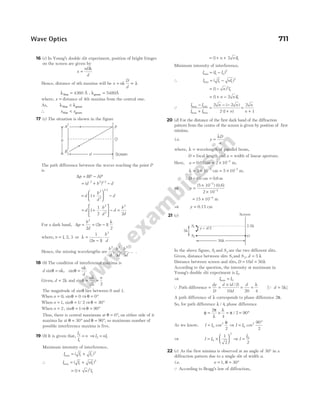
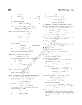
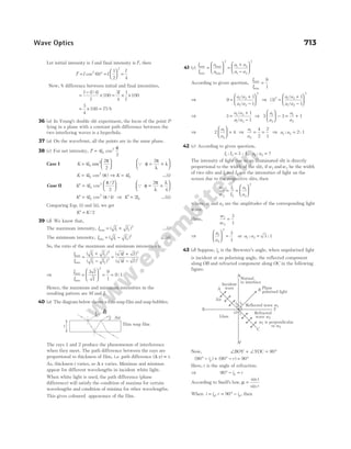
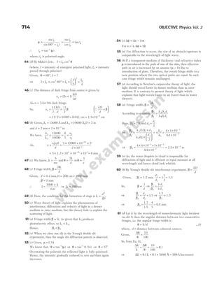
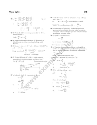
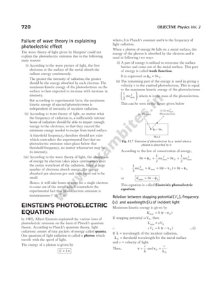
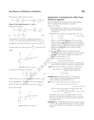
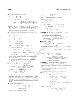
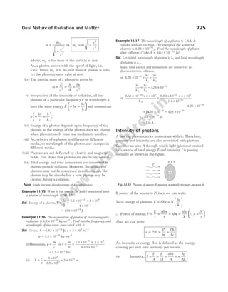
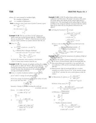
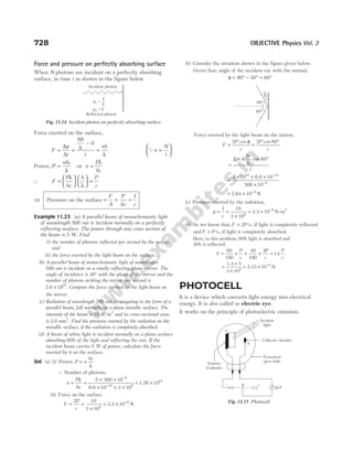
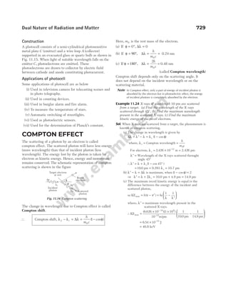
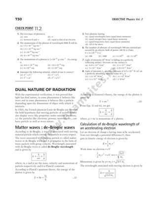
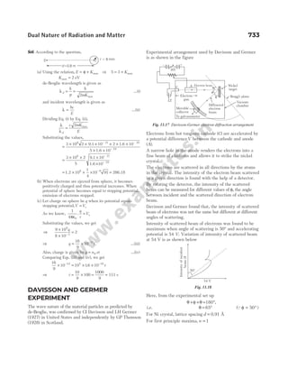
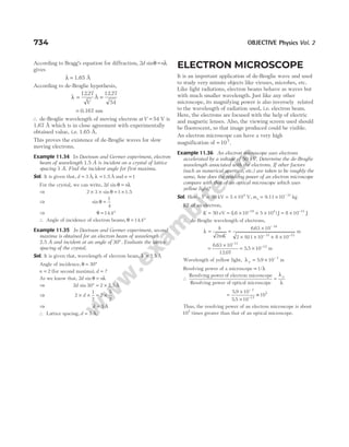
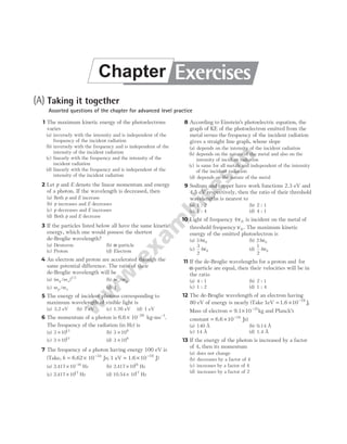
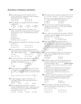
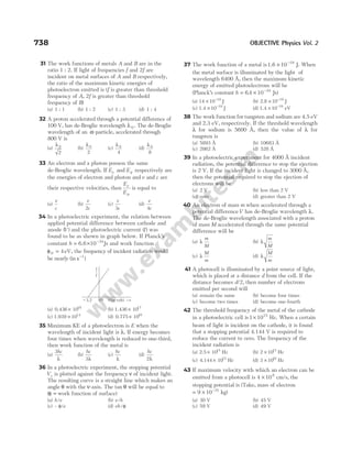
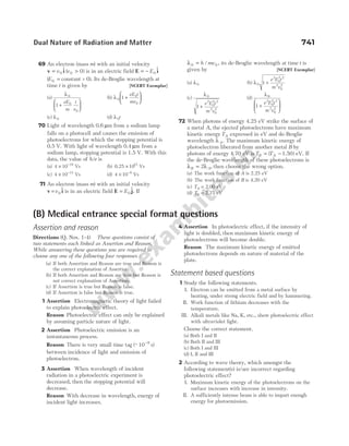
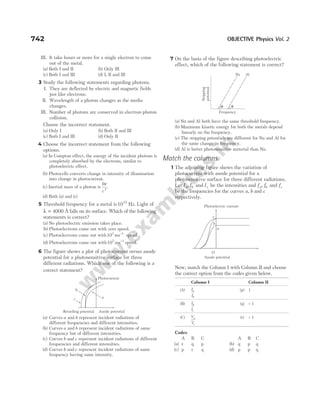
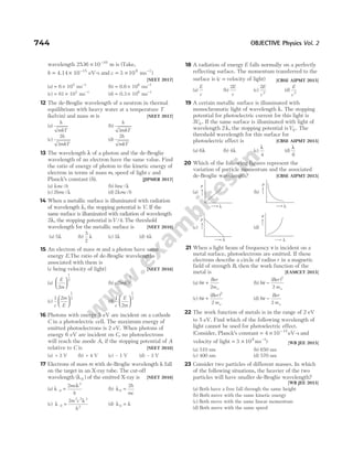
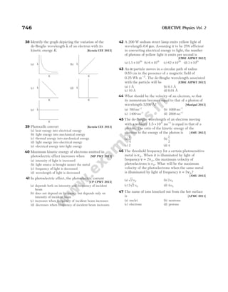
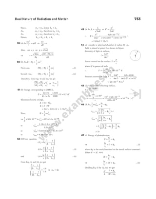
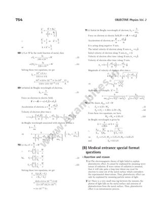
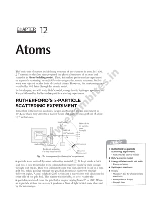
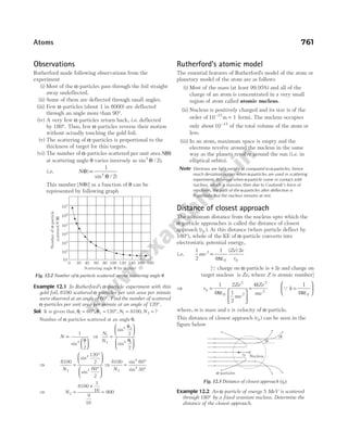
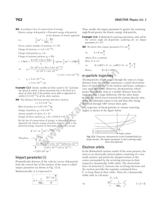
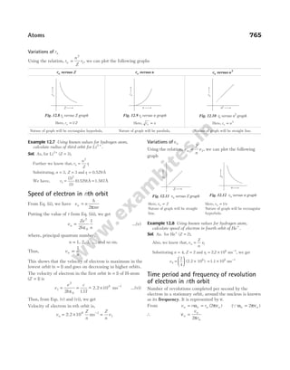
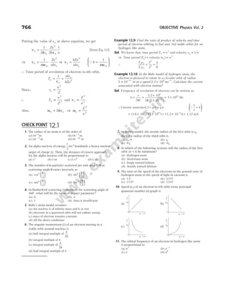
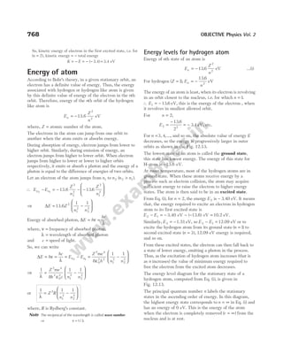
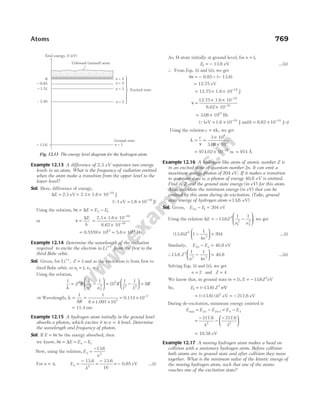
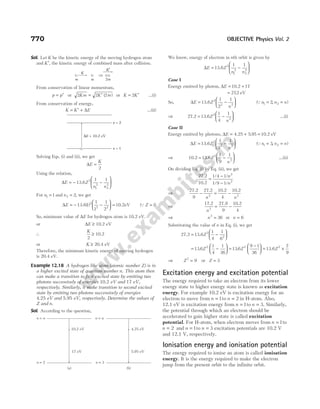
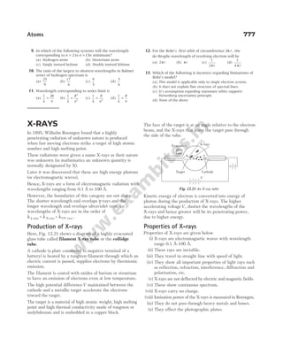
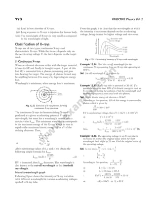
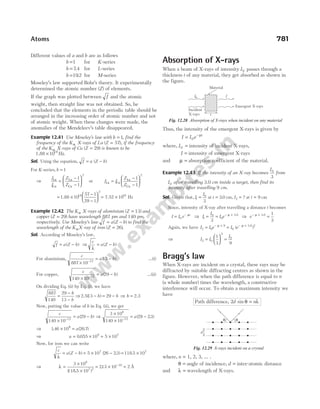
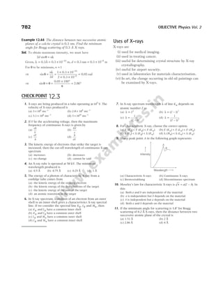
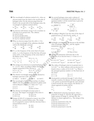
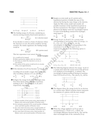
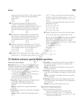
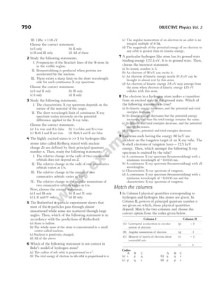
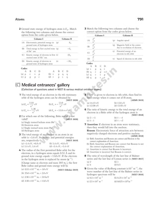
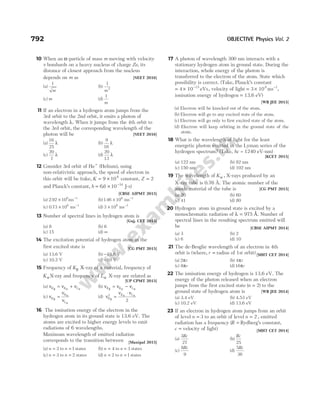
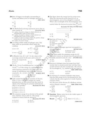
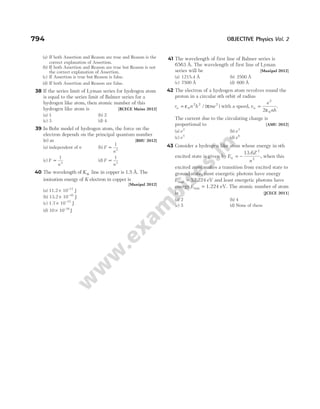
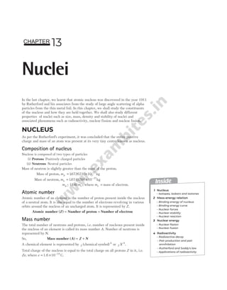
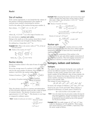
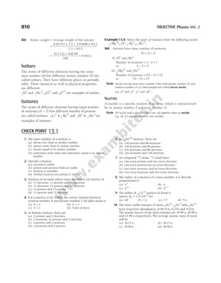
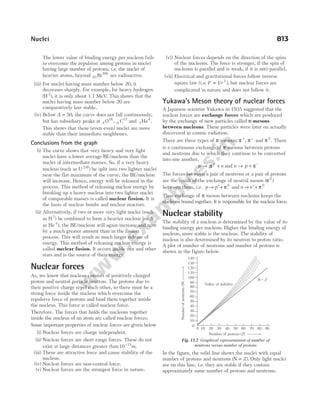
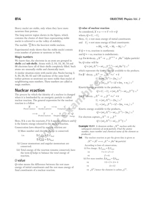
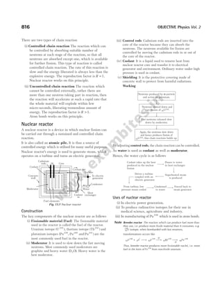
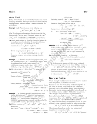
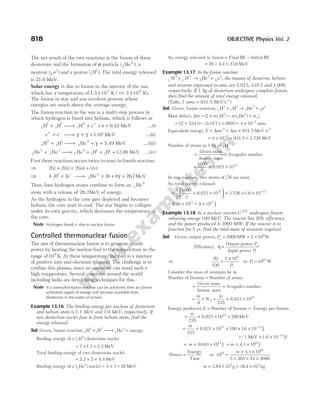
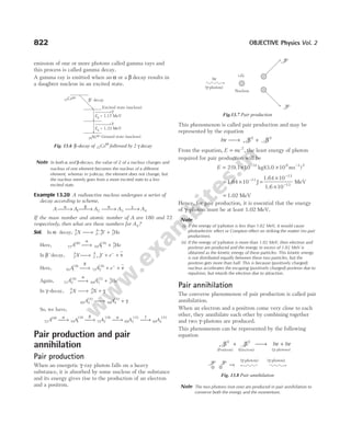
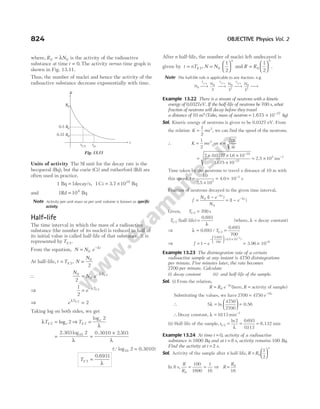
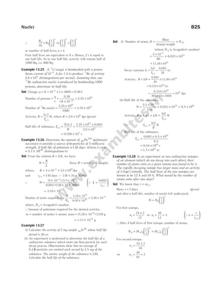
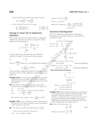
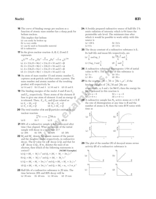
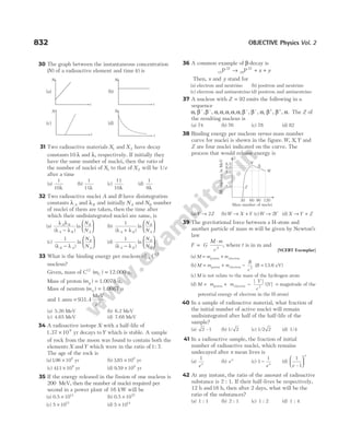
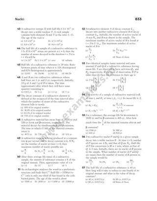
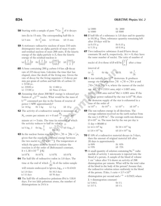

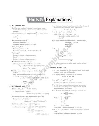
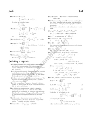
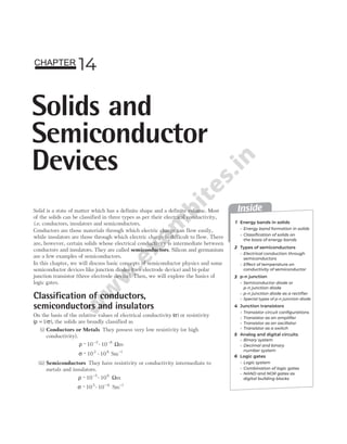
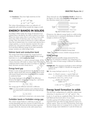
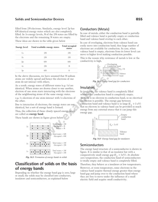
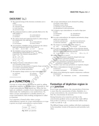
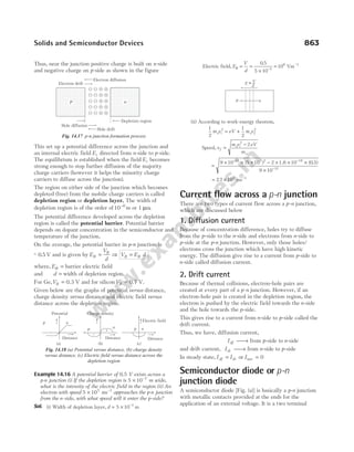
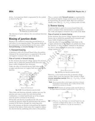
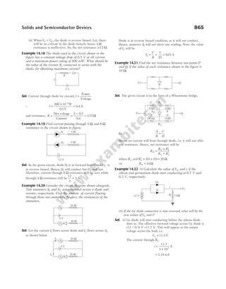
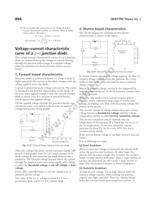
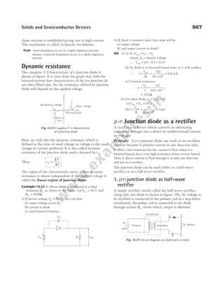
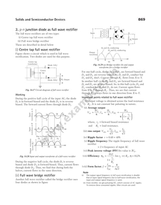
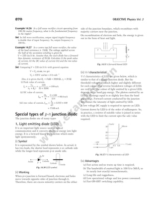
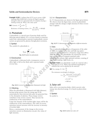
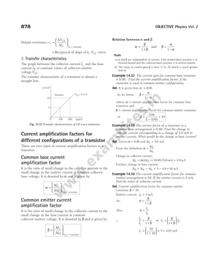
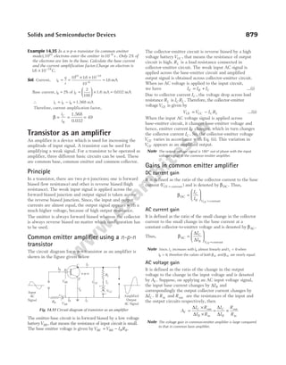
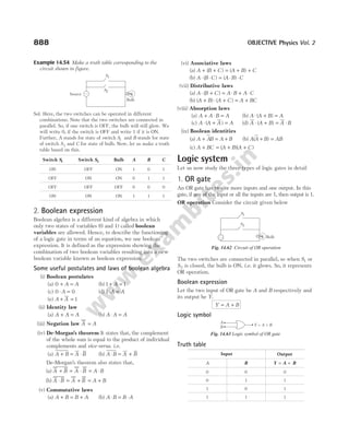
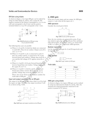
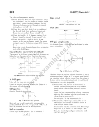
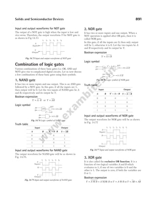
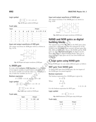
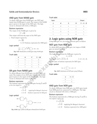
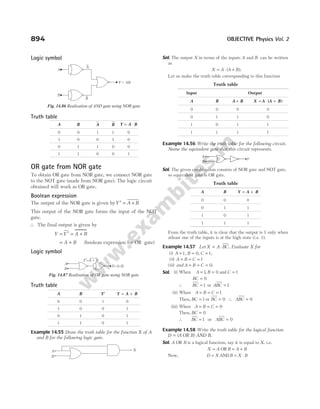
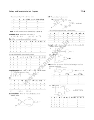
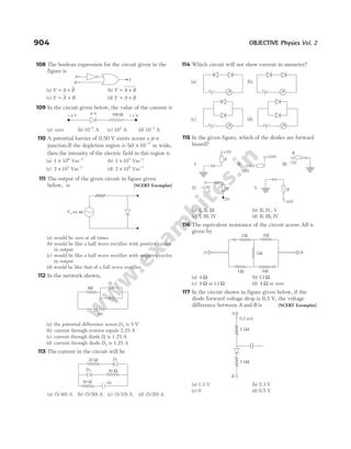
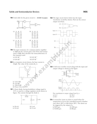
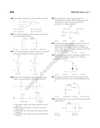
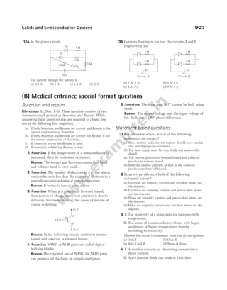
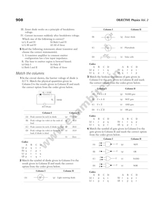
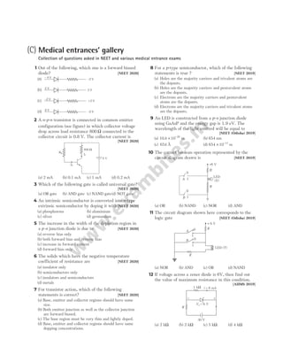
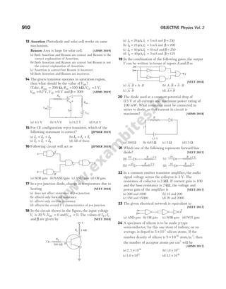
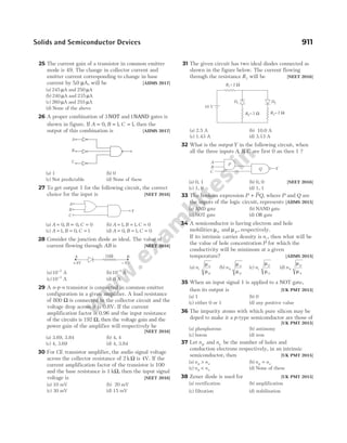
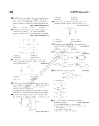
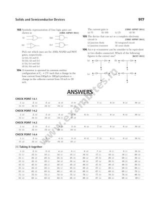
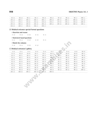
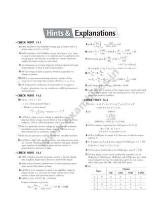
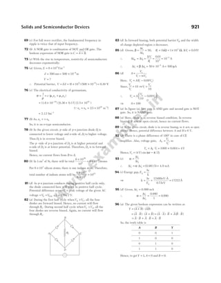
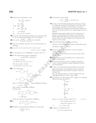
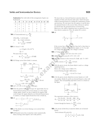
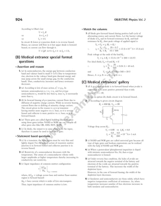
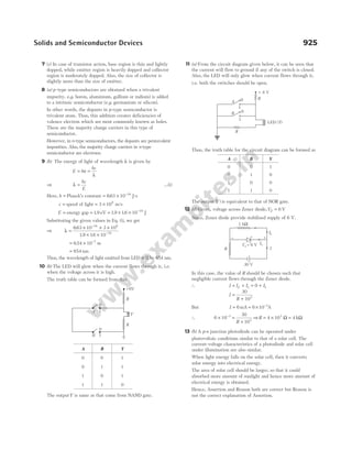
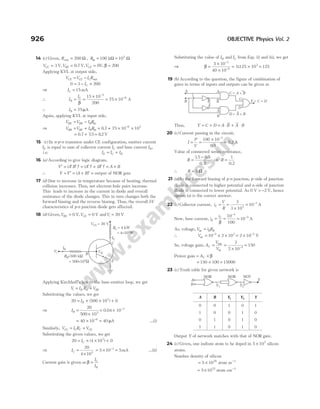
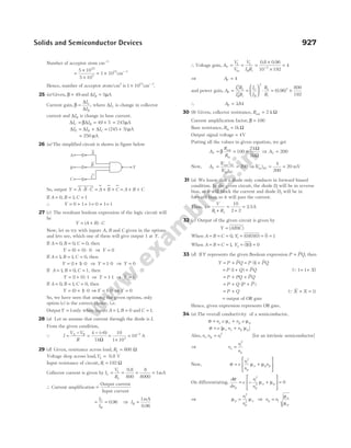


This document provides information about the publishing details of the book "NEET PHYSICS OBJECTIVE Volume02" by DC Pandey. It includes the names of the publishing managers, inner designer, page layout designer, proof readers and project heads involved in the production of the book. It also provides the copyright information and mentions that no part of the publication can be reproduced without permission from the publisher Arihant Prakashan. It directs the readers to the publisher's website and social media platforms for more information about their books.


