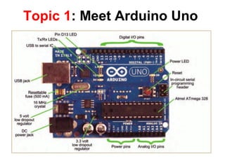
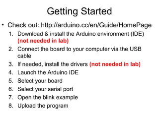
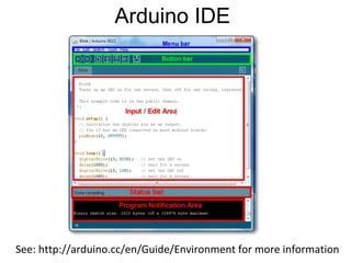
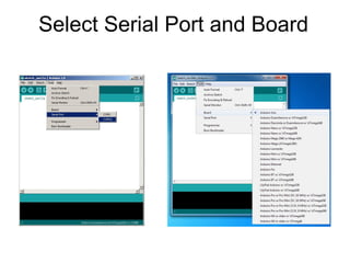
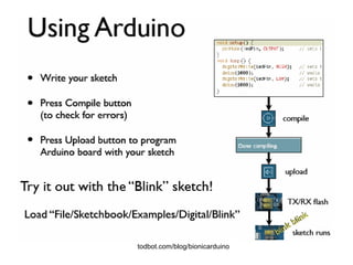
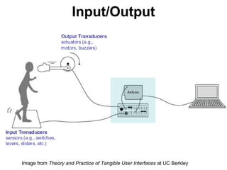
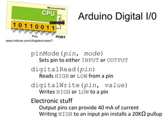
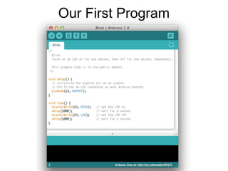
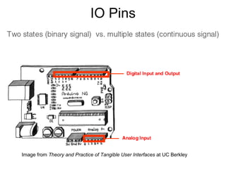
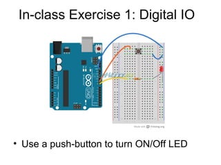
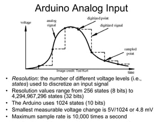
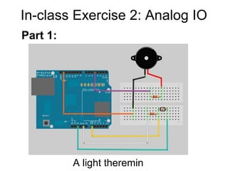
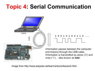
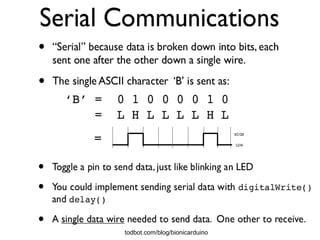
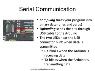
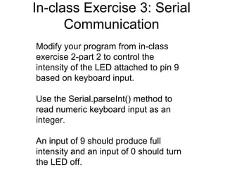
3. Getting Started
• Check out: http://arduino.cc/en/Guide/HomePage
1. Download & install the Arduino environment (IDE)
(not needed in lab)
2. Connect the board to your computer via the USB
cable
3. If needed, install the drivers (not needed in lab)
4. Launch the Arduino IDE
5. Select your board
6. Select your serial port
7. Open the blink example
8. Upload the program
8. Topic 2: Digital Input/Output
• Digital IO is binary
valued—it’s either on
or off, 1 or 0
• Internally, all
microprocessors are
digital, why?
1
0
9. Arduino Digital I/0
pinMode(pin, mode)
Sets pin to either INPUT or OUTPUT
digitalRead(pin)
Reads HIGH or LOW from a pin
digitalWrite(pin, value)
Writes HIGH or LOW to a pin
Electronic stuff
Output pins can provide 40 mA of current
Writing HIGH to an input pin installs a 20KΩ pullup
www.mikroe.com/chapters/view/1
13. Topic 3: Analog Input
• Think about music stored on a CD---an analog
signal captured on digital media
– Sample rate
– Word length
14. • Resolution: the number of different voltage levels (i.e.,
states) used to discretize an input signal
• Resolution values range from 256 states (8 bits) to
4,294,967,296 states (32 bits)
• The Arduino uses 1024 states (10 bits)
• Smallest measurable voltage change is 5V/1024 or 4.8 mV
• Maximum sample rate is 10,000 times a second
Arduino Analog Input
Image credit: Tod Kurt
15. How does ADC work?
• How does ADC work
• Excel Demonstration
16. • Can a digital devise produce analog
output?
Topic 3: Analog Output
• Analog output can be simulated using
pulse width modulation (PWM)
Image from Theory and Practice of Tangible User Interfaces at UC Berkley
17. Pulse Width Modulation
• Can’t use digital pins
to directly supply say
2.5V, but can pulse
the output on and off
really fast to produce
the same effect
• The on-off pulsing
happens so quickly,
the connected output
device “sees” the
result as a reduction
in the voltage
Image from Theory and Practice of Tangible User Interfaces at UC Berkley
18. PWM Duty Cycle
Fixed cycle length; constant
number of cycles/sec
Image credit: Tod Kurt
output voltage = (on_time / cycle_time) * 5V
19. PMW Pins
• Command:
analogWrite(pin,value
)
• value is duty cycle:
between 0 and 255
• Examples:
analogWrite(9, 128)
for a 50% duty cycle
analogWrite(11, 64)
for a 25% duty cycleImage from Theory and Practice of Tangible User Interfaces at UC Berkley
21. In-class Exercise 2: Analog IO
• Add a 330 ohm resistor and an LED to
pin 9
• Using the analogWrite() command,
set the intensity of the LED as a
function of the value of prReading
Part 2: Add an LED
22. Topic 4: Serial Communication
Image from http://www.ladyada.net/learn/arduino/lesson4.html
24. Serial Communication
• Compiling turns your program into
binary data (ones and zeros)
• Uploading sends the bits through
USB cable to the Arduino
• The two LEDs near the USB
connector blink when data is
transmitted
• RX blinks when the Arduino is
receiving data
• TX blinks when the Arduino is
transmitting data
todbot.com/blog/bionicarduino
26. Some Commands
• Serial.begin()
- e.g., Serial.begin(9600)
• Serial.print() or Serial.println()
- e.g., Serial.print(value)
• Serial.read()
• Serial.available()
• Serial.write()
• Serial.parseInt()
• Example Program
27. Serial-to-USB chip---what does it do?
Image from Theory and Practice of Tangible User Interfaces at UC Berkley
The LilyPad and Fio Arduino require an external USB to
TTY connector, such as an FTDI “cable”.
In the Arduino Leonardo a single microcontroller runs the
Arduino programs and handles the USB connection.
29. USB Protocol
• Much more complicated
Image from http://en.wikipedia.org/wiki/USB
30. In-class Exercise 3: Serial
Communication
Modify your program from in-class
exercise 2-part 2 to control the
intensity of the LED attached to pin 9
based on keyboard input.
Use the Serial.parseInt() method to
read numeric keyboard input as an
integer.
An input of 9 should produce full
intensity and an input of 0 should turn
the LED off.