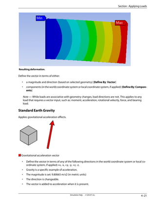
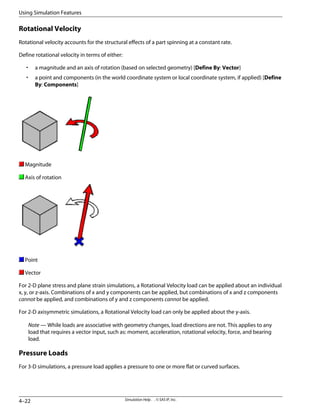
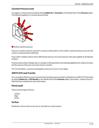
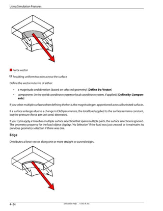
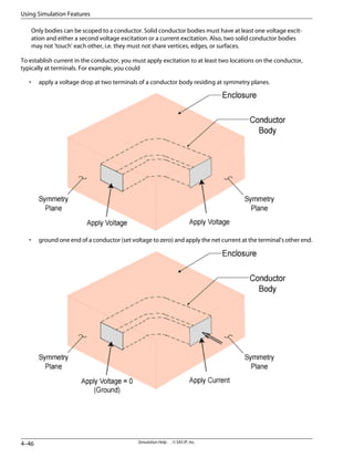
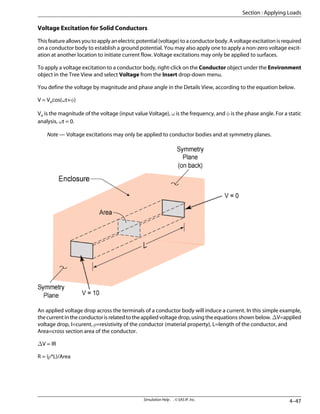
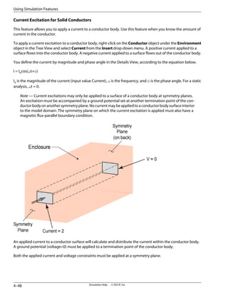
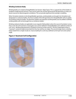
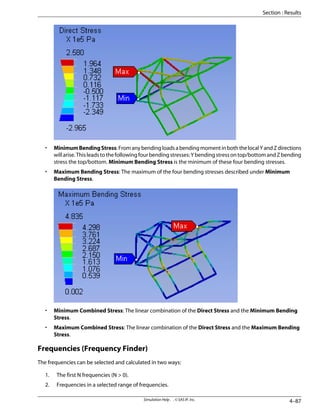
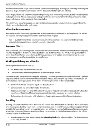
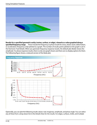
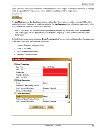
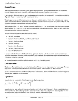
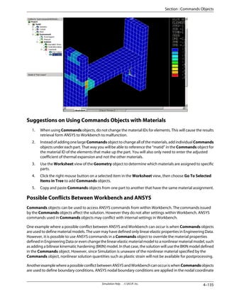
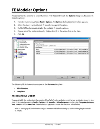
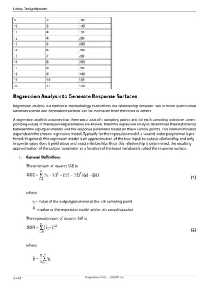
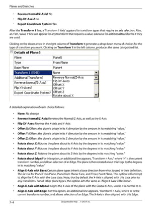
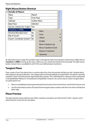
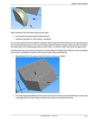
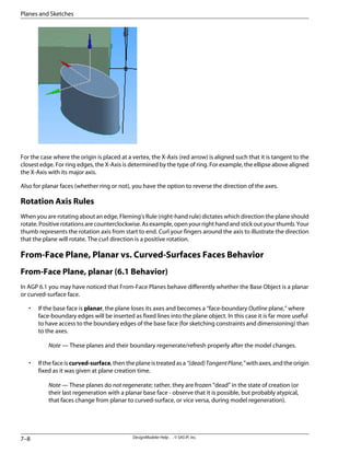
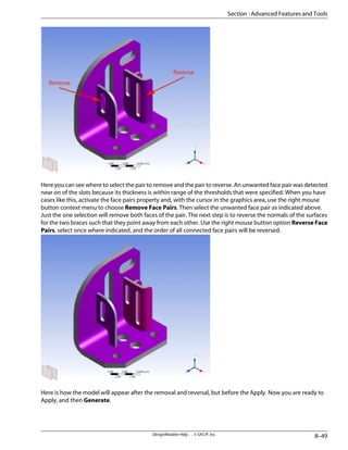
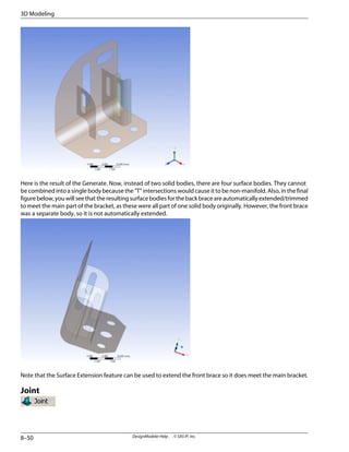
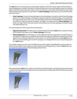
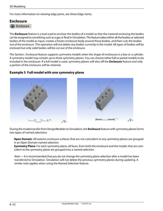
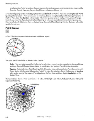
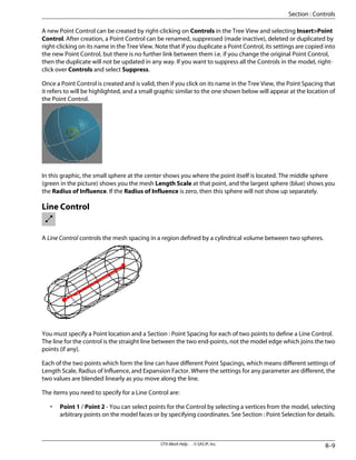
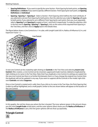
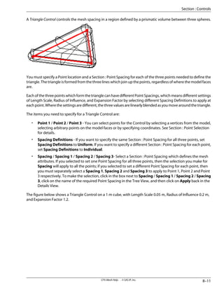
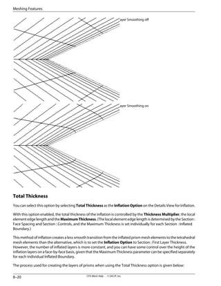
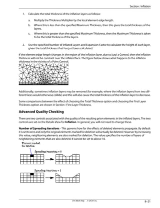
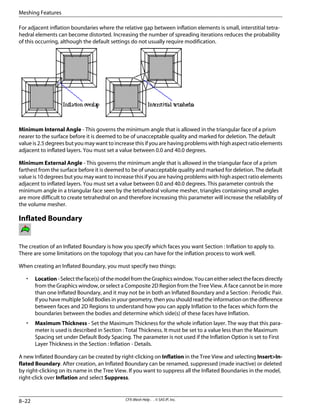
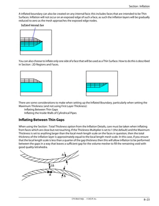
This document provides release notes for ANSYS Workbench 10.0, summarizing new features. Key additions include the ability to perform thermal transient simulations, enhanced results handling for sequenced simulations, new geometry and meshing options, and various usability improvements to the graphics and customization. New features are also listed for specific Workbench modules like DesignModeler, CFX-Mesh, and Simulation.


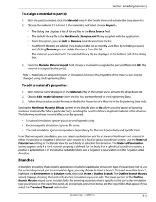
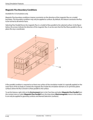
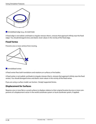
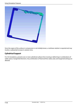
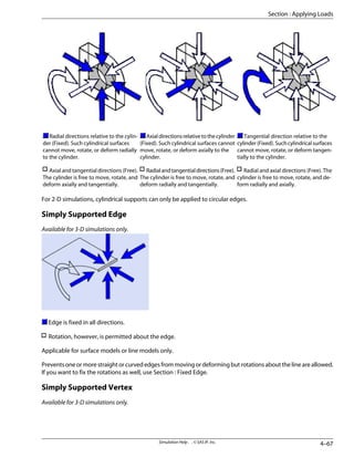
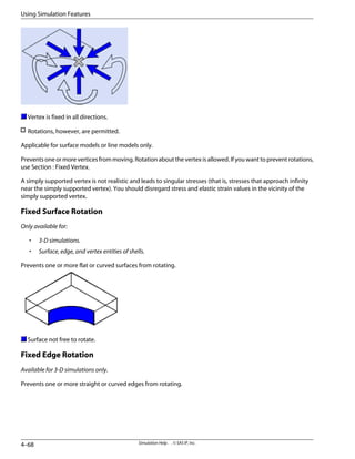
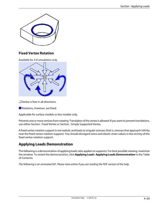
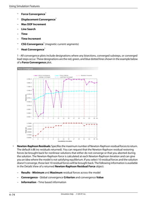
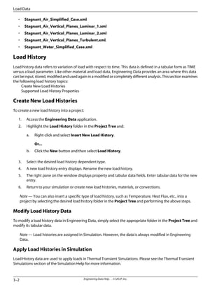
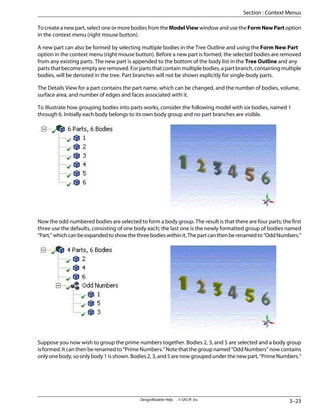
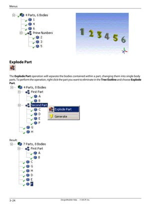
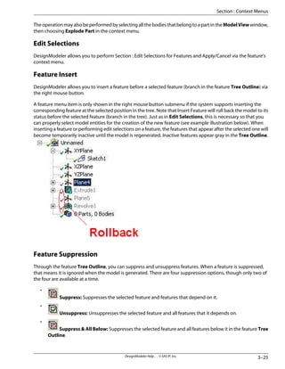
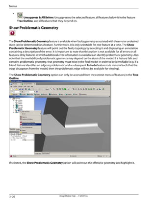
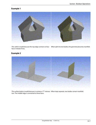
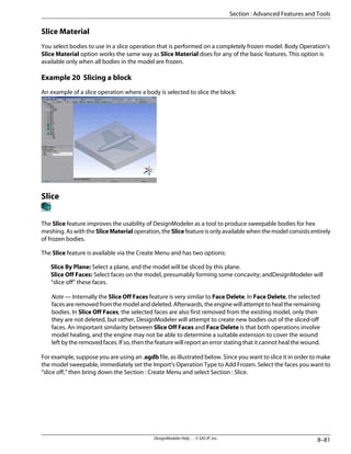
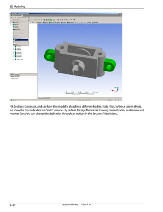
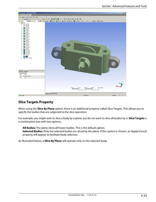
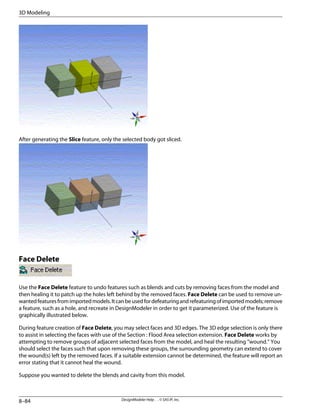
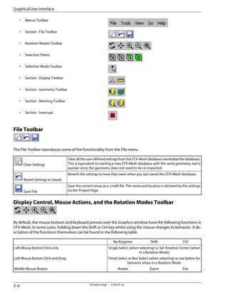
![– Using parentheses to nest search expressions.
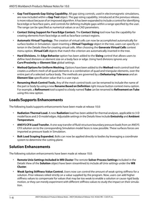
Asanexample,ifyouwantedtosearchforallsectionsintheSimulationHelpthatincludedboththewords
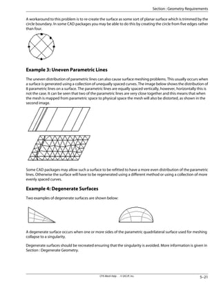
“probe” and “timeline”, a suggested term to enter in the Search tab would be “(probe and timel*) near
simulation”.
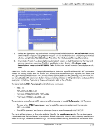
The Search tab in the Windows Help also includes checkboxes located at the bottom of the panel that
allow you to search previous results, match similar words, or search titles only.
• The Favorites tab in the Windows Help allows you to save topics that you frequently reference.
Context sensitive help for tree objects is available for some of the Workbench modules, and can be accessed by
highlighting the object and pressing the [F1] key.
Core ANSYS Help
A printable English version of the core ANSYS Help is available in PDF format1
from the ANSYS Customer Portal:
www.ansys.com> MY ANSYS> Customer Area> [Id and Password]> Product Information> Product Docu-
mentation> ANSYS Complete User's Manual Set (.pdf)
Workbench operation is heavily based on core ANSYS technology. The core ANSYS Help includes descriptions
of the underlying commands and elements that interact “behind the scenes” in Workbench. Also included is a
theory manual and several guides that detail the background and operation of several types of analyses.
Additional Documentation
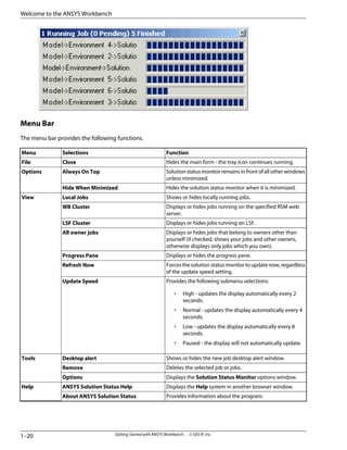
In addition to the online Workbench help, the following documentation is available:
• A printable English version of the Workbench Help is available in PDF format1
at:
<install directory>:Program FilesANSYS Incv100CommonFilesHelpen-usWorkbench.pdf for
Windows, and <install directory>:/v100/commonfiles/help/en-us/Workbench.pdf for UNIX.
• ANSYS Workbench Release Notes - print copy of the online version. The printed copy is included in the
product box.
• ANSYS Workbench Errata - print version only, included in the product box.
• ANSYS, Inc. Licensing Guide - print copy of the online version. The printed copy is included in the product
box.
• ANSYS Workbench Products Installation and Configuration Guide - print copy of the online version. The
printed copy is included in the product box.
1 - To view and print the contents of the PDF file, you must have Adobe Reader installed. A free reader download
is available at:
http://www.adobe.com/products/acrobat/readstep2.html
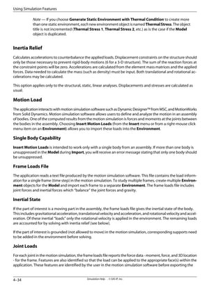
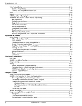
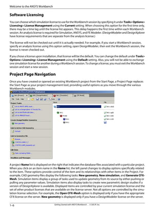
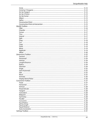
Workbench Projects and Databases
ANSYS Workbench uses projects to manage your workflow through the various task modules (DesignModeler,
Simulation, FE Modeler, DesignXplorer). A project helps you to manage the various sources of data needed to
complete an end-to-end CAE process. For example, if you insert a link to a CAD assembly into a project, an item
corresponding to the geometry source appears in a list on the Project Page. You may rename the item or re-link
1–3
Getting Started with ANSYS Workbench . . © SAS IP, Inc.
Section : Workbench Projects and Databases](https://image.slidesharecdn.com/ansysworkbench-221030093541-da346bf2/85/ANSYS-Workbench-pdf-27-320.jpg)
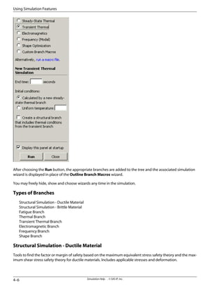
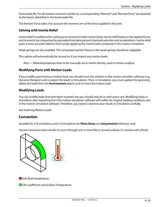
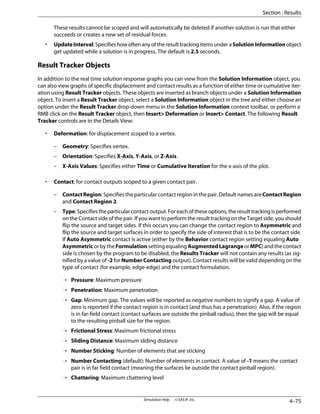
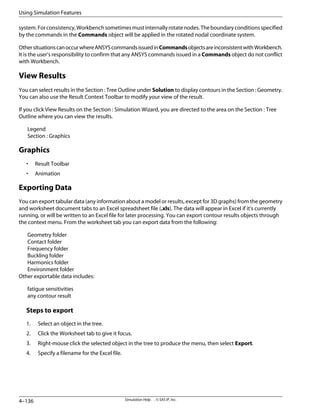
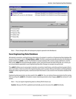
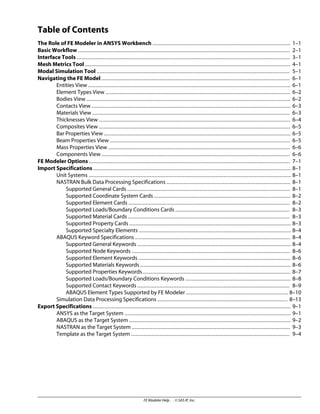
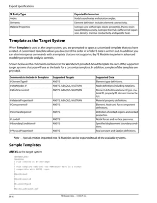
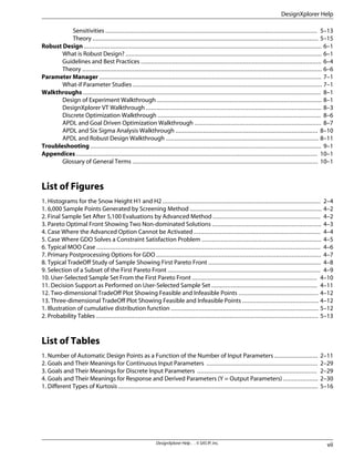
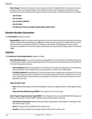
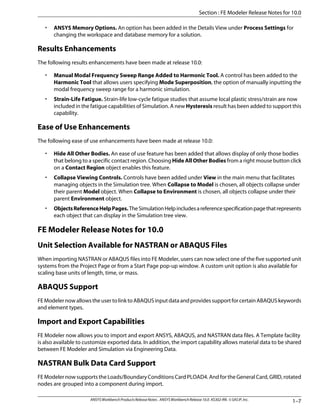
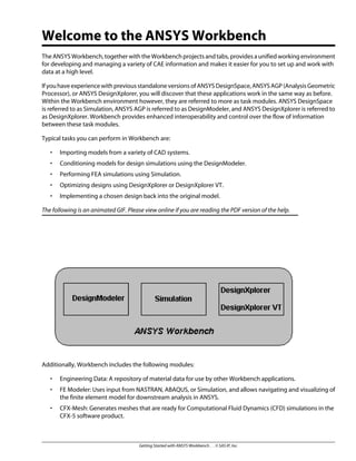
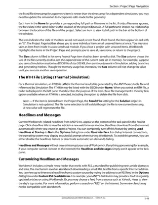
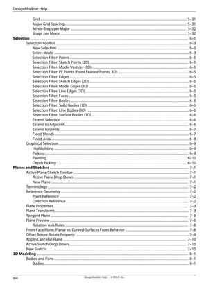
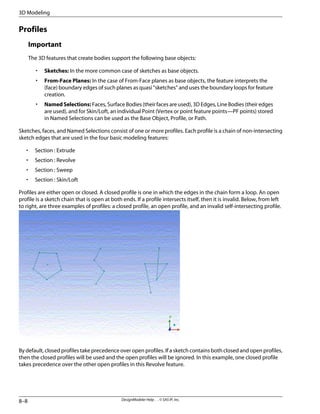
![• Select a template to create a new database or project. Template availability depends on licenses
available to your system.
– Click the Geometry template to create DesignModeler data.
– Click the Simulation template to create new Simulation data.
– Click the Finite Element Model template to create new FE Modeler data. You will be prompted to
open a NASTRAN bulk data file (*.bdf, *.dat, or *.nas). You can also choose to open an ABAQUS file
(*.inp or *.dat). a
– Click the CFX-Mesh template to create new CFX-Mesh data.
– Click the Empty Project template to proceed directly to the Workbench Project Page where you can
build a project that includes database files from various Workbench sessions.
Note—Advanceduserscanbuildcustomizedtemplates.RefertotheANSYSWorkbenchSoftware
Development Kit (SDK) in the Customization Guide for additional details.
• Open an Existing Database File. The Open area includes a drop down list of the most recently used
database files. Click on a file name to open the database file directly in the associated Workbench module.
Not all database types support a recent file list. You can click the Browse... button to open a database file
whose name is not in the file list, or you can access additional file types. For example, you can run a startup
macro by choosing a script file.
The list is filtered according to your choice in the drop down list.
– Choose Workbench Projects to display only Workbench database files (*.wbdb).
– Choose Simulations to display only Simulation database files (*.dsdb).
– Choose DesignModeler Geometry to display only DesignModeler database files (*.agdb).
– Choose DesignXplorer Studies to display only DesignXplorer database files (*.dxdb).
– Choose Finite Element Models to display only FE Modeler database files (*.fedb). a
– Choose CFX Meshes to display only CFX-Mesh database files (*.cmdb).
• The Tools section of the Start Page provides two selections:
– Options - Displays a dialog box that allows you to define Workbench options or preferences that
modify Workbench's behavior.
– Addins - This option launches the Addins manager dialog. This dialog allows you to load/unload
third-party add-ins that are specifically designed for integration within the Workbench environment.
You can enlarge the page by clicking the icon in the upper right corner of the Start Page. This will display more
information and minimize scrolling. You can toggle the Start Page back to the smaller size by clicking the icon
in the upper right corner again.
[a] If you choose to link to a NASTRAN or ABAQUS file, the Select Unit System dialog box appears on the Project
Pageandallowsyoutoselectoneofthefivesupportedunitsystems.ACustomchoiceisalsoavailablethatallows
you to scale base units of length , time, and mass.
1–5
Getting Started with ANSYS Workbench . . © SAS IP, Inc.
Section : Start Page Navigation](https://image.slidesharecdn.com/ansysworkbench-221030093541-da346bf2/85/ANSYS-Workbench-pdf-29-320.jpg)
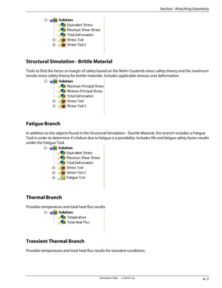
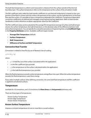
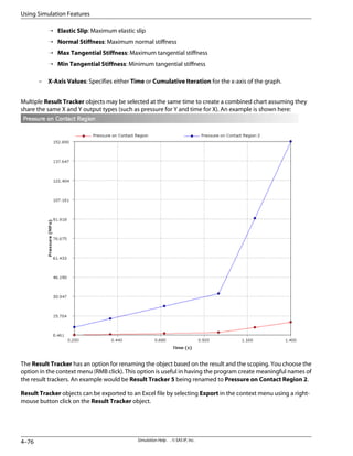
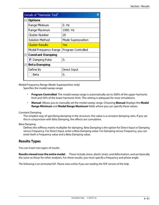
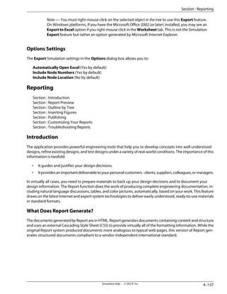
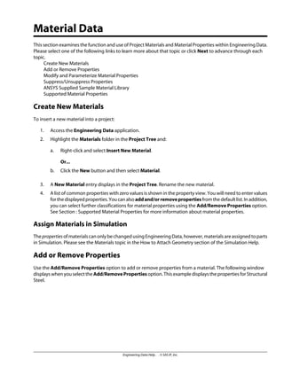
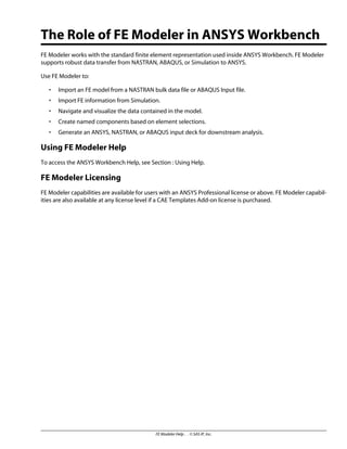
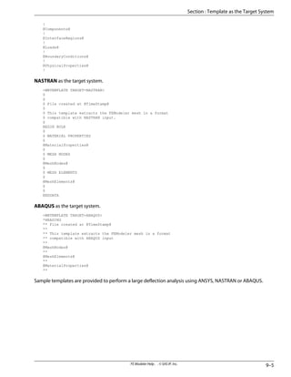
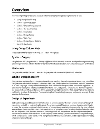
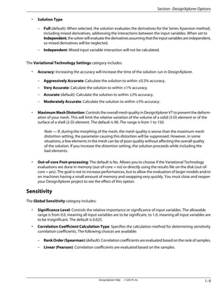
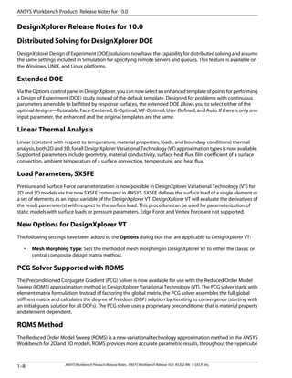
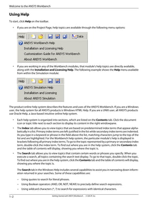
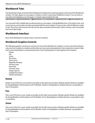
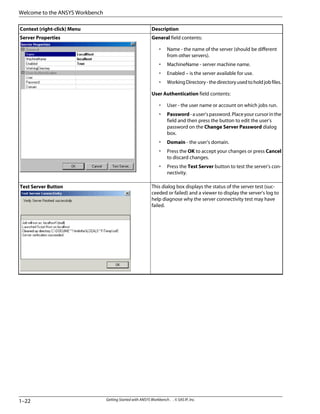
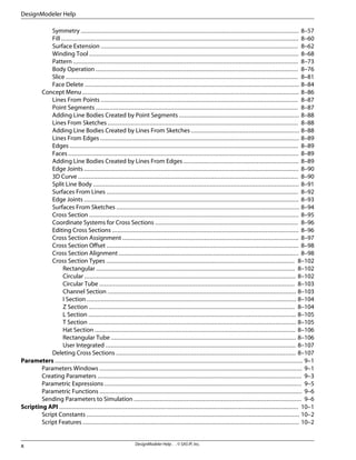
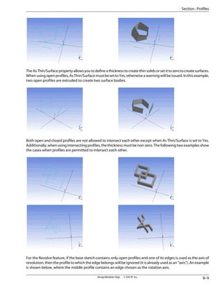
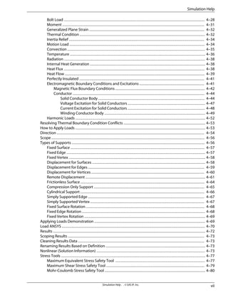
![Options Based on Selected Name
The following are summaries of the various options available based on your selection in the Name list:
• Options when you select Project name:
– Link to an ANSYS APDL input file.
– Link to a DesignXplorer VT Results file.
– Link to a NASTRAN bulk data file.a
– Link to an ABAQUS input file.a
– Transfer to DesignModeler to create new geometry, including assigning a name and specifying the
length unit to be used.
– Link to geometry from an open CAD system.
– Link to geometry from a file.
[a] If you choose to link to a NASTRAN or ABAQUS file, a Unit Selection section appears on the Project
Page that allows you to select one of the five supported unit systems. A Custom choice is also available
that allows you to scale base units of length , time, and mass.
• Options when you select CAD geometry name:
– Transfer to DesignModeler and open the selected geometry. This requires that you select a length
unit. Then choose Generate from within DesignModeler to display and use the geometry.
– Transfer to Simulation and open the selected geometry file.
– Transfer to CFX-Mesh and open the selected geometry file.
– Set Geometry Preferences. If you choose to import geometry from a CAD system, you can specify
preferences on how you would like the geometry to be transferred into Workbench. You can find a
description of these preferences included under Geometry Preferences. This section also includes
descriptions of geometry preferences you can specify in the Geometry Details View within Simulation.
– Re-link to geometry from an open CAD system.
– Re-link to geometry from a file.
Note — This option relocates a file that may have moved. The geometry itself does not update
until you select either of the Update options in Simulation.
– Various editing tasks.1
• Options when you select DesignModeler name:
– Transfer to DesignModeler and open the selected .agdb file.
– Create and open a copy of the selected .agdb file to add new geometry into the Project Page. This
will modify the project to have one more DesignModeler model in the hierarchy. It will also create a
file for the new copy.
– Transfer to Simulation based on the geometry in the selected .agdb file.
– Set Geometry Preferences.
– Delete...1
1–7
Getting Started with ANSYS Workbench . . © SAS IP, Inc.
Section : Project Page Navigation](https://image.slidesharecdn.com/ansysworkbench-221030093541-da346bf2/85/ANSYS-Workbench-pdf-31-320.jpg)
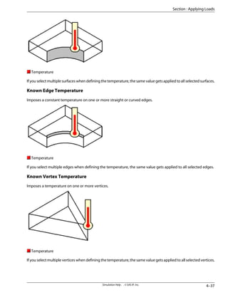
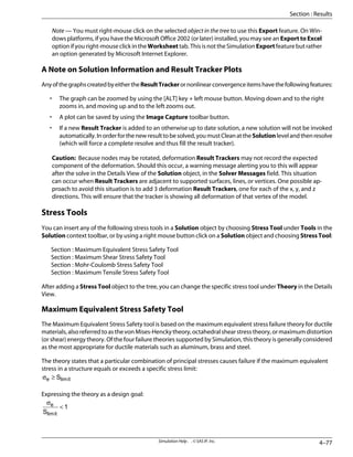
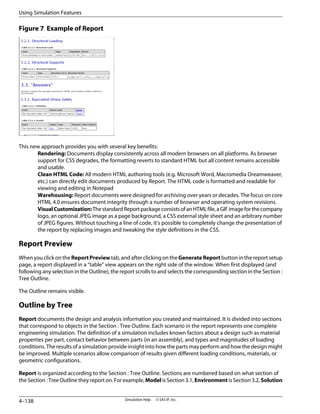
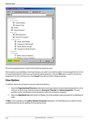
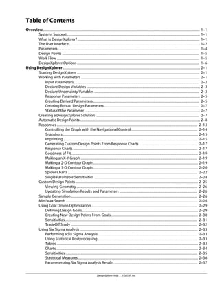
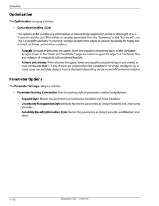
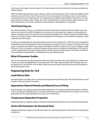
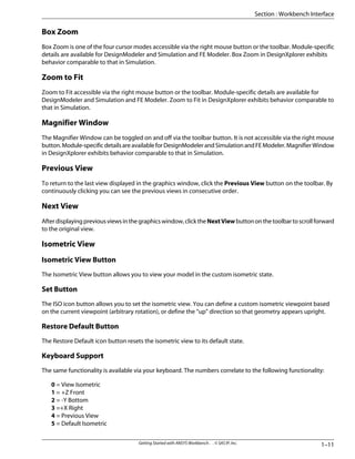
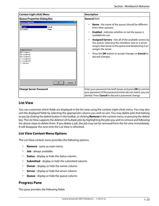
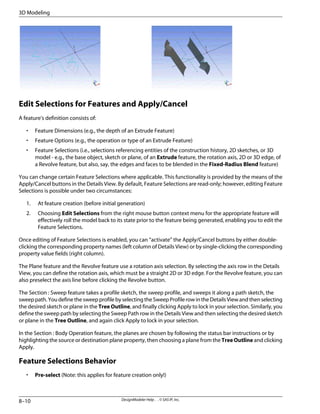
![• Options when you select Simulation name:
– Transfer to Simulation and open the selected .dsdb file.
– Start a new DesignXplorer “What If” study, DesignXplorer study, or DesignXplorer VT study based on
the analysis from the selected simulation.
– UpdatetheselectedsimulationwithparametersandgeometrythatwerespecifiedintheDesignModeler
file and in all associative geometry sources.
– UpdatetheDesignModelerorgeometryfileusingparametersfromtheselectedsimulation,thenupdate
the selected simulation with the latest geometry.
– Switch to ANSYS (if you have ANSYS installed) or FE Modeler from the selected Simulation environ-
ment(s). (List environments... appears if environment(s) were not yet viewed in Simulation. In this
case, click on List environments... to display the list, then click on the environment(s) that you want
to transfer.
– Various editing tasks.1
• Options when you select FE Modeler name:
– Transfer to FE Modeler and open the FE model from the selected .fedb file.
– Transfer to ANSYS (if you have ANSYS installed) and open or continue the analysis from the selected
environment.
– Various editing tasks.1
• Options when you select DesignXplorer name:
– Transfer to DesignXplorer and open the selected .dxdb file.
– Update the selected DesignXplorer study with the latest parameters and values from the input files.
– Various editing tasks.1
• Options when you select CFX-Mesh name:
– Various editing tasks.1
[1] If you choose Delete..., a dialog box prompts you to choose one of the following options:
• Delete only the selected item and any dependent items from the project (not any underlying files).
• Delete the project items and underlying files from the system. The underlying files are listed in the dialog
box. This option does not delete CAD files, NASTRAN files, or ANSYS input files.
You can also view Headlines and Messages on the Project Page regardless of which name is highlighted.
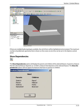
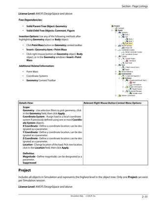
Name Dependencies
The indentation level of an item in the Name list implies dependency and data flow. In the examples mentioned
above, a design study depends on a simulation, which in turn depends on geometry. For parametric updates,
the system pushes parameter values upwards through the dependencies and then updates items top-down. If
Getting Started with ANSYS Workbench . . © SAS IP, Inc.
1–8
Welcome to the ANSYS Workbench](https://image.slidesharecdn.com/ansysworkbench-221030093541-da346bf2/85/ANSYS-Workbench-pdf-32-320.jpg)
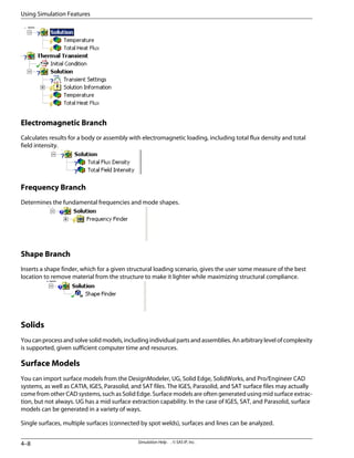
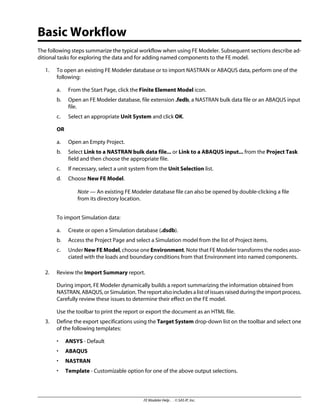
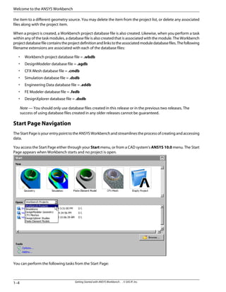
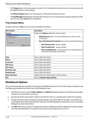
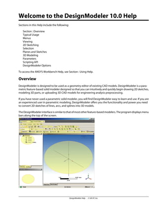
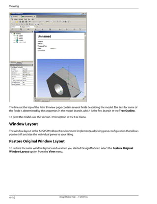
![Move the mouse pointer over a target to preview the resulting location for the pane. Arrow targets indicate ad-
jacent locations; a circular target allows tab-docking of two or more panes (to share screen space). Release the
button on the target to move the pane.
Abort the drag operation by pressing the [ESC] key.
Resize panes by dragging the borders.
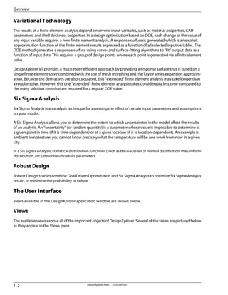
Workbench Behavior
When transitioning between the ANSYS Workbench modules, expect to encounter unique behavioral scenarios
as described below.
Open an Existing Database
From the Start Page when you choose to open an existing database, either Simulation (.dsdb), DesignModeler
(.agdb), or DesignXplorer (.dxdb), you are prompted to select a project name and location under the heading
entitled “Choose a default project name and location”. The project name is the default name for any .dsdb,
.agdb, or .dxdb. If you have an existing file with the same name in your project folder, you will be prompted for
permission to overwrite that file. If you want to preserve the existing file, choose a different project folder on the
Start Page.
Note — In order to maintain data link integrity, ANSYS Workbench must create these files for you upon
project startup. Failure to do so may cause the following error message to appear:
1–17
Getting Started with ANSYS Workbench . . © SAS IP, Inc.
Section : Workbench Behavior](https://image.slidesharecdn.com/ansysworkbench-221030093541-da346bf2/85/ANSYS-Workbench-pdf-41-320.jpg)
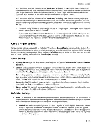
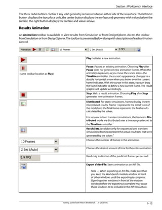
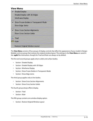
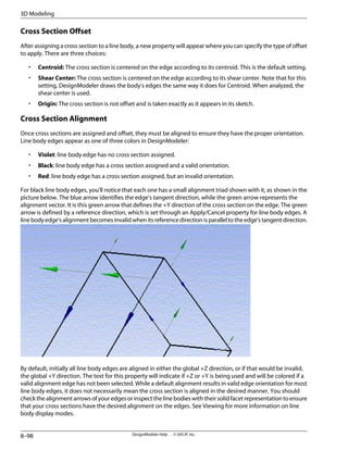
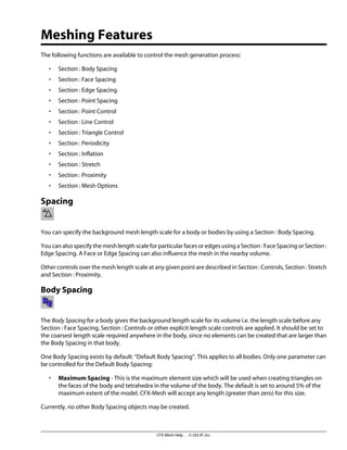
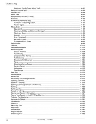
![Common Settings
The Common Settings options include general options governing graphics and interfacing.
Common Settings: Graphics Style
The Graphics Style category includes:
• Background Style: sets a solid graphic background or a gradient background that varies from top to
bottom, left to right, or diagonally. The default is the top to bottom gradient.
• Background Color: sets a graphic background color from the built-in color palette. The default color is
blue.
• Background Color2: sets a second graphic background color from the built-in color palette. The second
color is used for gradient background displays. For example, if you want a top-bottom gradient that starts
out white and ends up black, Background Color should be set to white and Background Color2 should
be set to black. The default color is white.
• Edge Color: sets the color of all edges from the built-in color palette. The default color is black.
• Unshared Edge Color: sets the color of all edges that are not touching. This is useful for finding modeling
errors in sheet parts. For example, if you see a red line running through the middle of a sheet part, you'll
know that the surfaces on either side of the line do not share an edge, even though it appears that they
do. Colors from the built-in color palette are available. The default color is red.
• Mesh Edge Color: sets the color of all meshed edges from the built-in color palette. The default color is
gray.
• Text Color: sets the color of all text from the built-in color palette. The default color is black.
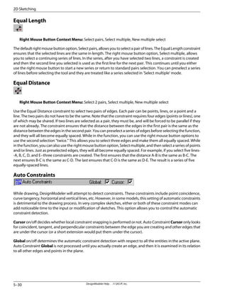
Common Settings: Graphics Interaction
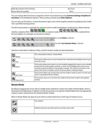
The Mouse Buttons category includes options for setting the various button controls on the mouse as well as
button combinations with the [Shift] and [Ctrl] keys.
The Rotation category has the following setting:
• Dynamic Viewing: If set to Yes and you are making a standard view change (such as front, back, left,
right, bottom, top, isometric, and Look At Face/Plane/Sketch) a short animation is drawn showing the
model moving/twisting toward its final pose. When set to No, there is no animation shown and the view
is immediately changed to the model's final pose. The default setting is Yes. Choose No if you are using
an older graphics card.
The Spaceball category has the following setting:
• Use Spaceball: enables the use of the Spaceball 3D import device (not supported in UNIX). The default
setting is Yes.
The Selection category has the following setting:
• Extend Selection Angle Limit (degrees): Sets a limit in degrees for what kind of face and edge angles
the system considers “smooth”. This affects the Extend to Adjacent and Extend to Limits Extend Selection
toolbar buttons in DesignModeler. Extend Selection buttons are also present in Simulation. The default
value is 20o
and the range is from 0o
to 90o
.
1–25
Getting Started with ANSYS Workbench . . © SAS IP, Inc.
Section : Workbench Options](https://image.slidesharecdn.com/ansysworkbench-221030093541-da346bf2/85/ANSYS-Workbench-pdf-49-320.jpg)
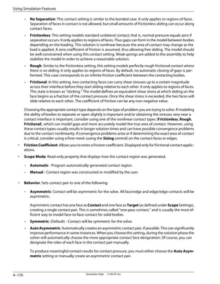
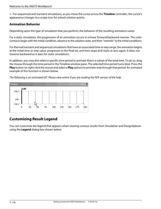
![Common Settings: User Interface
The Startup category includes:
• Custom Start Screen Configuration URL: Address of an XML configuration file that defines custom
content for the Start Page screen.
You can also develop and maintain several XML configuration files that each define various additional
applications to appear on the Start Page screen. Further details on this advanced task and on the overall
customization of Workbench are included in the ANSYS Workbench Software Development Kit (SDK)
section of the Customization Guide
• Load Headlines at Startup: Indicates if the Headlines and Messages section should appear on the
Project Page when Workbench is started. The default is Yes.
• Custom RSS Feed Address: URL to a custom RSS to allow the Headlines and Messages section to list
headlines from that RSS.
The Value Display category includes:
• NumberofSignificantDigits: Sets the number of digits that appear for numbers throughout Workbench.
The default is 5 and the range is from 3 to 8. This setting affects only the numbers that are displayed. It
does not imply any numerical round off of internal calculations.
The Menus/Toolbars category includes:
• Show Beta Options: Allows testing of unreleased Workbench features. The default is No. Beta features
remain untested in this release and therefore are neither documented nor supported.
• Omit Text on Toolbars: Indicates if text tips are to be omitted from toolbar buttons. The default is No.
The File Management category includes:
• ”Save As” Preferred Default: Determines the default settings when you choose File> Save As.... The
following choices are available:
– Name and location of most recent link (e.g., CAD file) [default]
– Location of most recently saved database
Under certain conditions such as creating a new simulation from CAD, the default file name and location
are based on the geometry file. If you prefer to organize databases in a separate location, adjusting this
option may provide a more convenient default.
The CAD Licensing Management category includes:
• CADLicensing:DetermineswhethertheCADlicensewillbereleasedwhennotinuse.DuringDesignXplorer
studiesandSimulationparametermanagerruns,whentheCADlicenseisaccessedrepeatedly,thelicense
may not always be available if the Release option is used. The following choices are available:
– Release (default)
– Hold
The Solution Status Startup Management category includes:
Getting Started with ANSYS Workbench . . © SAS IP, Inc.
1–26
Welcome to the ANSYS Workbench](https://image.slidesharecdn.com/ansysworkbench-221030093541-da346bf2/85/ANSYS-Workbench-pdf-50-320.jpg)


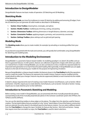
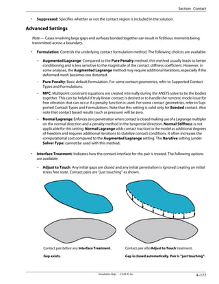
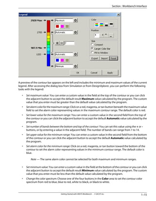
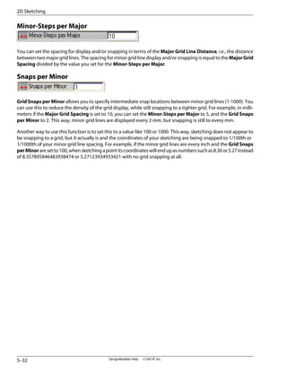
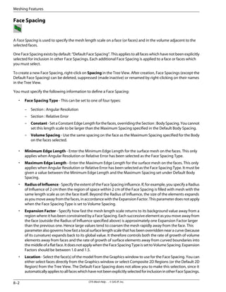
![To start the process of creating a model, open DesignModeler from the Start Page by selecting Geometry. To
begin sketching, choose one of the sketch tools from the Section : Draw Toolbox. For this example, click on the
Section : Rectangle tool. You can simply sketch the rectangle by left clicking the top left corner location and
dragging the mouse to the lower right corner location and clicking.
Show me.1
[http://www.ansys.com/techmedia/1-create_rectangle.html]
Additional edges can be added by choosing the appropriate sketch tool. Exact locations and dimensions are not
critical at this point. For example, click on the Section : Circle tool to add two circles representing the desired
holes in the finished model. Simply sketch the rough locations. You can finalize the hole placement when editing
the model.
Show me.1
[http://www.ansys.com/techmedia/2-add_hole_circles.html]
DesignModeler Help . . © SAS IP, Inc.
1–4
Welcome to the DesignModeler 10.0 Help](https://image.slidesharecdn.com/ansysworkbench-221030093541-da346bf2/85/ANSYS-Workbench-pdf-68-320.jpg)
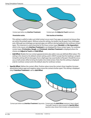
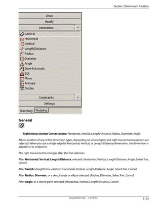
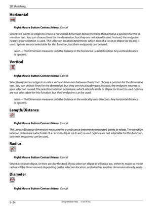
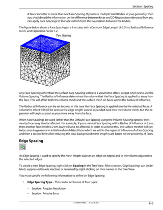
![Aftercompletingtheroughsketch,selecttheDimensionstoolboxandadddimensionsbypickingtheappropriate
tool in the Section : Dimensions Toolbox. DesignModeler provides a number of dimensioning tools similar to
those found in advanced CAD systems. Select the Section : Diameter dimension tool, and then select the two
circles to be dimensioned. Unlike drafting systems, DesignModeler does not automatically position dimension
labels, but you can do so manually, via mouse drags.
Show me.1
[http://www.ansys.com/techmedia/3-dimension_hole_circles.html]
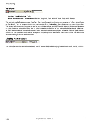
You may choose to use the Section : Display Name/Value tool in the Section : Dimensions Toolbox to choose the
Name and/or Value display (only Names shown here).
Show me.1
1–5
DesignModeler Help . . © SAS IP, Inc.
Section : Process for Creating A Model](https://image.slidesharecdn.com/ansysworkbench-221030093541-da346bf2/85/ANSYS-Workbench-pdf-69-320.jpg)
![[http://www.ansys.com/techmedia/4-display_name.html]
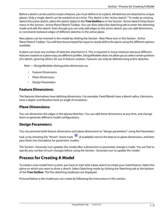
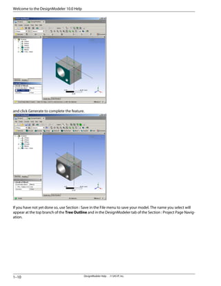
After defining the 2D sketch, you can generate a 3D solid model using one of the feature creation operations in
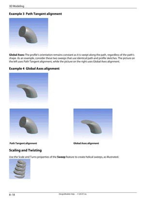
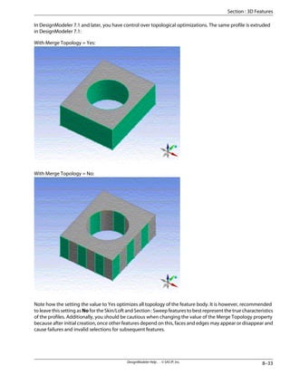
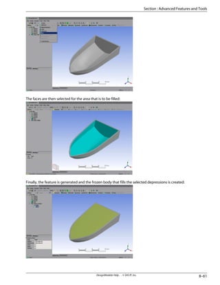
DesignModeler. For example, you can revolve or sweep a profile to create a solid. DesignModeler also hasSection :
Skin/Loft capabilities that allow you to join multiple sketch profiles to form a solid. After the dimensions have
been resolved, you can generate the 3D model by clicking Extrude, Revolve, etc. from the Section : 3D Features
Toolbar. For this example, the sketch is extruded to a depth of 30 millimeters (mm). Click on Extrude, then specify
the extrusion depth in the “Feature Details” window. Here the sketch is shown in the Isometric View, which you
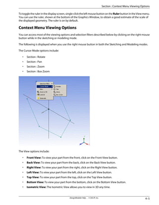
can see by right-clicking in the Model View and selecting Section : Isometric View from the context menu.
Oncethedepthoftheextrusionisdeterminedandentered,youmustclickontheGeneratebutton.Inthisexample,
the 2D pattern of the sketch is extruded into a 3D solid.
Show me.1
[http://www.ansys.com/techmedia/5-generate_3_d.html]
DesignModeler Help . . © SAS IP, Inc.
1–6
Welcome to the DesignModeler 10.0 Help](https://image.slidesharecdn.com/ansysworkbench-221030093541-da346bf2/85/ANSYS-Workbench-pdf-70-320.jpg)
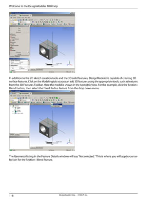
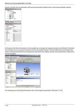
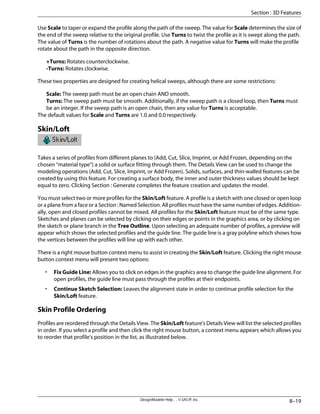
![At this point, you can return to Sketching mode by clicking the Sketching tab under the Tree Outline to finalize
the dimensions. Using the Section : Edit tool in the Section : Dimensions Toolbox, simply pick the dimension
value and modify it in the details window. Alternatively, you can edit a dimension through the Details Window
of the Sketch. In this example, we change the value of D1 in Sketch1 to 20 mm.
Show me.1
[http://www.ansys.com/techmedia/6-change_dimension.html]
After modifying the dimensions, click on the Generate button from the Section : 3D Features Toolbar to update
the changes.
1–7
DesignModeler Help . . © SAS IP, Inc.
Section : Process for Creating A Model](https://image.slidesharecdn.com/ansysworkbench-221030093541-da346bf2/85/ANSYS-Workbench-pdf-71-320.jpg)
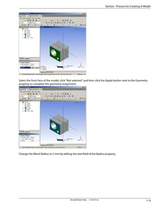
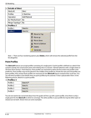
![Show me.1
[http://www.ansys.com/techmedia/7-add_3d_blend.html]
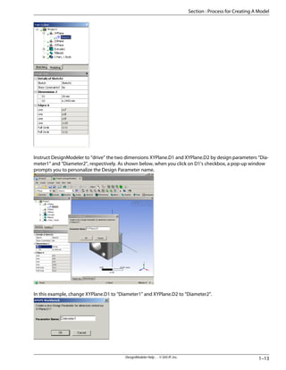
Now would be a good time to add Design Parameters to the model. One way to do this is to use the “driven”
check marks next to the feature/plane dimensions in the Feature Details window.
For example, click the checkbox of the radius dimension of FBlend1. A pop-up dialog will appear, asking
whether you want to create a new Design Parameter.
1–11
DesignModeler Help . . © SAS IP, Inc.
Section : Process for Creating A Model](https://image.slidesharecdn.com/ansysworkbench-221030093541-da346bf2/85/ANSYS-Workbench-pdf-75-320.jpg)
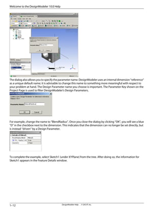
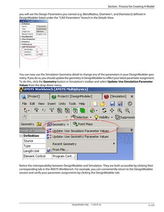
![and click Generate to update the model.
Show me.1
[http://www.ansys.com/techmedia/8-generate_parameters.html]
The model is now complete and ready for simulation. With the ANSYS Workbench you have the option to apply
this model to a new Simulation scenario with the click of a tab. For this example, click the ANSYS Workbench
Project tab. You will see details of your DesignModeler database listed and buttons to access the functionality
of Simulation.
1–15
DesignModeler Help . . © SAS IP, Inc.
Section : Process for Creating A Model](https://image.slidesharecdn.com/ansysworkbench-221030093541-da346bf2/85/ANSYS-Workbench-pdf-79-320.jpg)
![To return to the Section : Project Page Navigation, click the Project tab. Now both your original DesignModeler
geometry project and your current Simulation session are listed. For more information about the Section : Project
Page Navigation, click on the Help button (signified by a white question mark in a blue circle) in the Toolbar or
the Help menu.
Show me.1
[http://www.ansys.com/techmedia/9-run_in_ds.html]
1 - Video demonstrations require internet access.
• PC Users: videos play directly in the help system.
• UNIX Users: videos do not play directly in the help system. However, you can view them by copying the
published URL to an internet browser capable of playing back Flash video files.
DesignModeler Help . . © SAS IP, Inc.
1–18
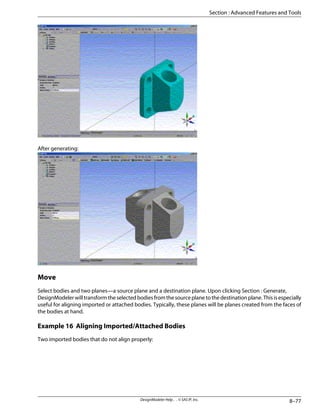
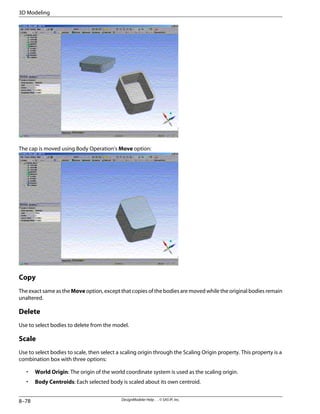
Welcome to the DesignModeler 10.0 Help](https://image.slidesharecdn.com/ansysworkbench-221030093541-da346bf2/85/ANSYS-Workbench-pdf-82-320.jpg)


![Units can only be set when creating a new DesignModeler model from the Start Page. When running Design-
Modeler in stand-alone mode, the Units preferences can be changed through the Options dialog box.
The toolbar also reflects differences in file-management functionality. When DesignModeler operates in the
ANSYS Workbench, the Start Over and Close DesignModeler options are available.
• Section : New
• Section : Start Over
• Section : Open
• Section : Close DesignModeler
• Section : Save
• Section : Save As
• Section : Export
• Section : Attach to Active CAD Geometry
• Section : Import External Geometry File
• Section : Import and Attach Options
• Section : Run Script
• Section : Print
• Section : Auto-save Now
• Section : Restore Auto-save File
• Section : Recent AGDB Files
• Section : Recent Imports
• Section : Recent Scripts
• Section : Exit Workbench
A description of each file-management option follows:
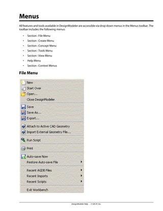
New
Hotkey: [Ctrl]-N
Use the New option to begin a new model. Before the new model is started, you will be prompted to save your
current model, if necessary. Choose the unit setting in the Units pop-up window:
DesignModeler Help . . © SAS IP, Inc.
3–2
Menus](https://image.slidesharecdn.com/ansysworkbench-221030093541-da346bf2/85/ANSYS-Workbench-pdf-86-320.jpg)
![You may choose a unit setting for the new session, or by checking the box you can always use the default value
for future models without being prompted. The Units pop-up window can always be reactivated through the
Options dialog box. The new model will be unnamed.
Start Over
Available only in the ANSYS Workbench mode, use the Start Over option to begin a new model. Note that your
model name is retained.
Open
Hotkey: [Ctrl]-O
Use the Open option to open a saved DesignModeler model (extension: .agdb).
Close DesignModeler
Available only in the ANSYS Workbench mode, this option will close the DesignModeler tab in the Section :
Project Page Navigation. If the model requires saving, you will be prompted to save it.
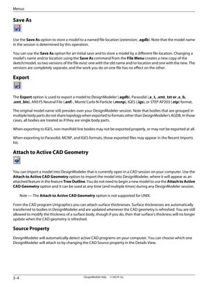
Save
Hotkey: [Ctrl]-S
The Save option stores a model with the .agdb extension at the specified file location.
3–3
DesignModeler Help . . © SAS IP, Inc.
Section : File Menu](https://image.slidesharecdn.com/ansysworkbench-221030093541-da346bf2/85/ANSYS-Workbench-pdf-87-320.jpg)
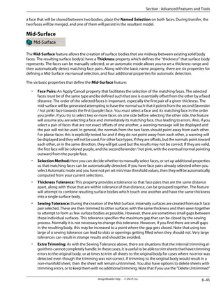
![will be required to reattach/redefine those loads that are lost, but should expect associativity to be
maintained from that point forward.
• Surface bodies imported into DesignModeler include numerical references to the parent part or assembly
and Pro/ENGINEER quilt ID. For example, a part named H103 with three Pro/ENGINEER quilts 1, 2, and 3
will be identified as H103[1], H103[2] and H103[3].
Solid Edge
• When importing a Solid Edge assembly, make sure that no two components use the same component
name. This will result in the second component being displayed on top of the first.
• A closed surface body will be imported into DesignModeler as a solid body since Solid Edge considers
this body as a solid.
• Solid Edge recommends that part documents contain only one body, otherwise a duplicate set of para-
meters and variables may be imported.
SolidWorks
• A limitation imposed by SolidWorks in relation to geometry and the API processing exists if a sketch is
revolved 180 degrees. As a result, the faces generated on either portion of the revolution are identified
as the same. However if the revolution angle is changed, they now become different faces; one retains
the original identification and the second a new one. This creates an associativity break if the angle of
revolution is modified to or from 180 degrees.
Unigraphics
• Closed surface models from Unigraphics can only be imported to ANSYS Workbench Products through
UG NX 1.0.1.2 and up. Persistence may not be maintained when a Unigraphics import is first refreshed in
old databases prior to Release 8.0.
• If you refresh Unigraphics geometry in DesignModeler, the Unigraphics interface uses Unigraphics User
Defined Objects (UDO) to store persistent IDs. To maintain the associativity of the geometry between
Unigraphics and DesignModeler, you need to Import/Attach the Unigraphics geometry file in Design-
Modeler and save the part file at the end of a Unigraphics session (plug-in), or save the part file from
within DesignModeler (reader). At update/refresh time, you will need to set the Reader Save Part File
property to Yes. The part file will be saved at the end of an attach process using the same file name in the
same directory. The current part file will be backed up by changing the extension of the file to bak before
saving the part. Make sure that the file is not set to read-only.
Note — You should avoid setting Reader Save Part File to Yes on UNIX platforms if a CAD file is
open.
Import and Attach Options
Geometry Options
Several options are available for the various types of geometry imported or attached to DesignModeler. Some
options are available only for specific CAD packages, while others apply to some, but not all CAD packages. Below
is a description of the geometry options, followed by a chart showing which options are available for each CAD
package or file type.
• Simplify Geometry - If yes, DesignModeler will simplify the surfaces and curves of the model into analyt-
ical geometry where possible. Default is no.
DesignModeler Help . . © SAS IP, Inc.
3–12
Menus](https://image.slidesharecdn.com/ansysworkbench-221030093541-da346bf2/85/ANSYS-Workbench-pdf-96-320.jpg)
![Help Menu
This online documentation for DesignModeler is provided as a set of HTML files in standard Microsoft HTML Help
for Windows. See Using Help for detailed usage instructions.
• ANSYS DesignModeler Help: Click this button to access the ANSYS Workbench Help. By default you are
taken to the DesignModeler section, where you can search by keywords.
Note — You can also access the online documentation by pressing the [F1] hotkey.
• Installation and Licensing Help: Click this button to access the ANSYS Workbench Installation and Li-
censing Help.
• About ANSYS DesignModeler: Click this button to access copyright, software build date and version,
and service pack version information.
Context Menus
Context menus are only accessible using the right mouse button.
Suppress/Hide Part and Body
The functionality to Suppress and Hide parts and bodies behaves exactly as in Simulation.
• Suppress implies Hide.
• Suppress/Hide is possible from both the Tree Outline and the Model View window.
• In the Model View window, suppression issued on a body (edge, face) applies to the body as a whole.
• Hide means the body is not visible.
• Suppress means it is not visible and it is also not exported to Simulation.
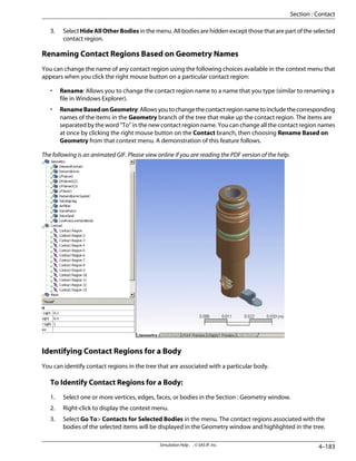
• Select All Bodies will select all visible bodies in the model.
Right mouse button Options:
Hide Body
Right clicking on a body in the Tree Outline and clicking Hide Body may hide the body. A light check mark icon
will appear in the Tree Outline when a body is hidden.
Hide All Other Bodies
Right clicking on Hide All Other Bodies functions as the name implies.
DesignModeler Help . . © SAS IP, Inc.
3–20
Menus](https://image.slidesharecdn.com/ansysworkbench-221030093541-da346bf2/85/ANSYS-Workbench-pdf-104-320.jpg)
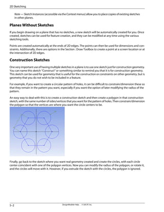
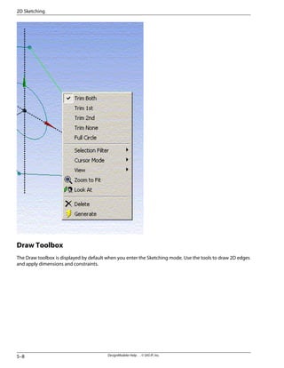
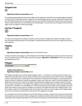
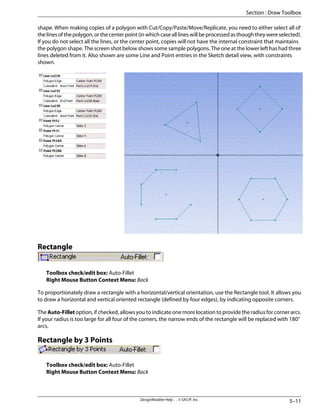
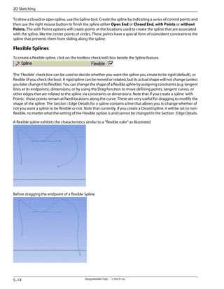
![2D Sketching
Important
In order to use the sketcher efficiently, it is important to note that, in the context of constraints and di-
mensions, the system treats 2D edges as if they extend beyond their endpoints.
To create a solid body from your sketch, all connected chains of edges must be closed.
Most multiple-task operations are done by one of two input sequences:
• Click (press and release), move, click sequence
• Press (hold), drag, release sequence
Many sketching operations make heavy use of the right mouse button context menu for optional input.
Some also have optional input via toolbox check/edit box options. In the following, these options are
listed after the operation's icon:
Toolbox check/edit box: Option 1, Option 2, …
Right Mouse Button context menu: Option 1, Option 2, …
The right mouse button Back option is very much like a “micro” undo during the sketching operation.
The sketching operations support Undo/Redo functionality, but note that each plane stores its own
Undo/Redo stacks.
Also note that while in Sketching mode, you can always exit whatever function you are in and go to the
general Select mode, by pressing the [ESC] key. Note that if you have accessed a window external to the
DesignModeler, you will need to click somewhere back in the DesignModeler window before the [ESC]
key will be usable.
Undo
Use the Undo command to rescind the last sketching action performed.
Redo
Use the Redo command to “redo” a sketching action previously undone.
Sketches and Planes
A sketch is a collection of 2D edges. A plane can hold any number of sketches. Whenever you create a 2D edge
using one of the tools in the Section : Draw Toolbox, it is added to the currently “active” sketch. You can click the
Section : New Sketch button to create a new sketch in the currently “active” plane, or you can select an already
existing sketch to make it the new active sketch.
DesignModeler Help . . © SAS IP, Inc.](https://image.slidesharecdn.com/ansysworkbench-221030093541-da346bf2/85/ANSYS-Workbench-pdf-129-320.jpg)
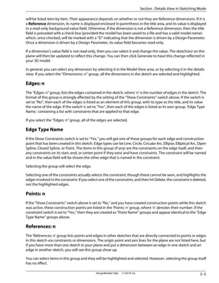
![Details View in Sketching Mode
While in Sketching mode, the Details View can contain three types of information:
• Section : Sketch Details
• Section : Edge Details
• Section : Dimension Details
All the detail views are broken into groups, listed in boldface and proceeded by a [-], followed by the information
that pertains to that group. Items within a group have a title on the left followed by a value on the right. The
value column may be grayed-out, if the item is read-only, and cannot be edited.
Sketch Details
Details of Sketch
The first item under the Details of Sketch group, lists the sketch name in a value field that can be edited. This allows
you to change the name of a sketch. All names and labels that you create must be unique, start with a letter, and
contain only letters, digits and underscores. Spaces and hyphens are not recognized. If your supplied name does
not end in a numeric and is not unique, a numeric will be added at the end. For example, MyPlane becomes
MyPlane2, and MySketch5 becomes MySketch6.
The next item in this group is 'Show Constraints,' and its value can be Yes or No. Changing this value has a major
effect on how the rest of the Sketch Detail View will look, as will be explained below.
Clicking the 'Details of' group selects the sketch and highlights all the edges in the sketch.
Dimensions: n
The 'Dimensions: n' group lists the dimension, where 'n' is the number of dimensions created with this active
sketch. This group will not appear if there are no dimensions as part of the sketch. If there are dimensions, they
DesignModeler Help . . © SAS IP, Inc.
5–4
2D Sketching](https://image.slidesharecdn.com/ansysworkbench-221030093541-da346bf2/85/ANSYS-Workbench-pdf-132-320.jpg)
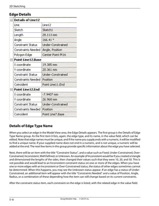
![Following this there are Point Name groups for each of the edge's base, end, and center points, when appropriate.
These will show the X and Y position of the point, its constraint status, and the constraints on the point.
You can select items in the Edge Details similar to selecting from the Sketch Details. When you create something
new, you are returned to the Sketch Details. You can also return there by clicking the New Selection icon.
Dimension Details
Details of NAME
When you select a dimension in the Model View area, the Dimension Details appear. The first group in the Di-
mension Details is always 'Details of NAME,' where NAME is the name of the selected dimension. The first item
inthisgroupidentifiesthedimensiontype,andliststhedimension'snameinthevaluefield,whichcanbeedited.
Note that dimension names must be unique, and if the name you supply ends with a numeric, it will be modified
to find a unique name. If your supplied name does not end in a numeric and is not unique, then a numeric will
be added at the end. The next item lists the Value. If the value field is not read-only, then you can modify it.
Clicking Generate will then propagate that change through the 3D model.
The following items identify the points or edges associated with this dimension. Then, the next item allows you
to state whether or not this is a Reference Only dimension. If it is, you will not be able to change its value and its
name will be shown enclosed in parentheses, and its value can change as the sketch is changed. Finally, there
is a switch that allows you to prevent the position of this dimension from automatically being updated when its
associated geometry moves.
To go back to the Sketch Details, you can select the Active Sketch Drop Down menu on the toolbar, or [ESC] can
be used to clear the selections and go back to the Sketch Details. Note that if you have accessed a window ex-
ternal to DesignModeler, you will need to click somewhere back in DesignModeler window before the [ESC] key
will be usable.
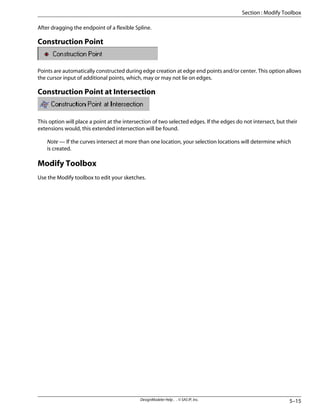
Right mouse button option items with (icon) check marks
When using the Fillet, Chamfer, Split, Equal Distance constraint, or general Dimension features, you can click the
right mouse button to display by check mark (depressed icon) the current mode for the option shown. Shown
here are the Fillet trim mode options.
Note — Full circle here implies no trimming.
5–7
DesignModeler Help . . © SAS IP, Inc.
Section : Details View in Sketching Mode](https://image.slidesharecdn.com/ansysworkbench-221030093541-da346bf2/85/ANSYS-Workbench-pdf-135-320.jpg)
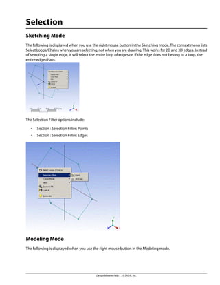
![The Selection Filter options include:
• Section : Selection Filter: Points
• Section : Selection Filter: Edges
• Section : Selection Filter: Faces
• Section : Selection Filter: Bodies
Selection Toolbar
Use the Select tool to perform these tasks:
• Preselect entities for sketching and modeling functions.
• Select sketch entities (curves, points, and dimensions).
• Select model vertices, edges, faces, or bodies.
• Extend the current selection.
To select multiple entities, hold the [Ctrl] key down while selecting additional entities when in the modeling
mode.
New Selection
Use the New Selection button to clear the current selection, if any, and start a new selection. This also ends the
current sketching state.
Select Mode
The Select Mode toolbar button allows you to select items designated by the Selection Filters through the Single
Select or Box Select drop down menu options.
6–3
DesignModeler Help . . © SAS IP, Inc.
Section : Selection Toolbar](https://image.slidesharecdn.com/ansysworkbench-221030093541-da346bf2/85/ANSYS-Workbench-pdf-163-320.jpg)
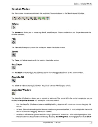
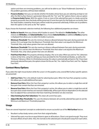
![•
Single Select (default): Click on an item to select it.
•
Box Select: Selects all filtered items by dragging a selection box. There are two types of selections
based on the dragging direction. When the dragging is from left to right, items completely enclosed in
theboxareselected.Whenthedraggingisfromtherighttotheleft,itemscompletelyandpartiallyenclosed
in the box are selected. Note the difference in the hash marks along the edges of the box to help you de-
termine which box selection type will be performed.
The edges fully inside the box are selected
Drag a selection box from the left to the right
The edges inside the box and the edges touching the box are
selected
Drag a selection box from the right to the left
You can use the [Ctrl] key for multiple selections in both modes. Switching the select mode from Single Select
to Box Select or vice versa does not affect the current selection.
DesignModeler Help . . © SAS IP, Inc.
6–4
Selection](https://image.slidesharecdn.com/ansysworkbench-221030093541-da346bf2/85/ANSYS-Workbench-pdf-164-320.jpg)
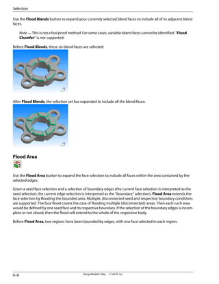
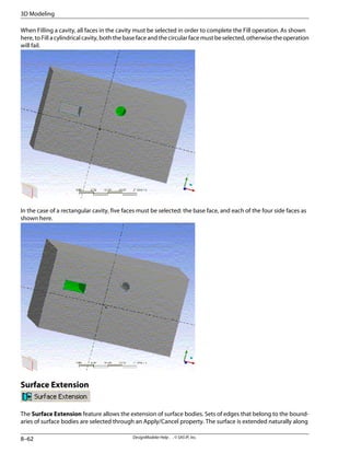
![After Flood Area, the two regions are flooded up to the bounding edges:
Graphical Selection
Tips for working with graphics
• You can rotate the view while selecting geometry by dragging your middle mouse button.
• You can zoom in or out by holding the Shift key and dragging with the middle mouse button.
• You can pan the view by using the arrow keys or holding the [Ctrl] key and dragging with the middle
mouse button.
• Click the interactive triad to quickly change the Model View window.
• You can zoom in or out by scrolling the mouse wheel.
• To rotate about a specific point in the model, switch to Rotate mode and click the model to select a rotation
point.
• To roll the model, click the Rotate button, then hold down the left mouse button outside of the model as
shown.
• To select more than one surface, hold the [Ctrl] key and click the surfaces you wish to select.
• You may customize the mouse operations in the Section : Workbench Options.
Highlighting
Highlighting provides visual feedback about the current pointer behavior (e.g. select surfaces) and location of
the pointer (e.g. over a particular surface). The surface edges are highlighted in colored dots.
Picking
A pick means a click on visible geometry. A pick becomes the current selection, replacing previous selections. A
pick in empty space clears the current selection in the modeling mode.
6–9
DesignModeler Help . . © SAS IP, Inc.
Section : Graphical Selection](https://image.slidesharecdn.com/ansysworkbench-221030093541-da346bf2/85/ANSYS-Workbench-pdf-169-320.jpg)
![Byholdingthe[Ctrl]keydown,youcanaddunselecteditemstotheselectionandselecteditemscanberemoved
from the selection.
Painting
Painting means dragging the mouse on visible geometry to select more than one entity. A pick is a trivial case
of painting. By holding the [Ctrl] key down, painting will append all appropriate geometry touched by the
pointer to the current selection.
Depth Picking
Depth Picking allows you to pick obscured entities through the Z-order. Whenever more than one entity lies
under the pointer, the graphics window displays a stack of rectangles in the lower left corner. The rectangles are
stacked in appearance, with the topmost rectangle representing the visible (selected) geometry and subsequent
rectangles representing geometry hit by a ray normal to the screen passing through the pointer, front to back.
The stack of rectangles is an alternative graphical display for the selectable geometry.
Highlighting and picking behaviors are identical and synchronized for geometry and its associated rectangle.
Moving the pointer over a rectangle highlights both the rectangle and its geometry. [Ctrl] key and painting be-
haviors are also identical for the stack. Holding the [Ctrl] key while clicking rectangles picks or unpicks associated
geometry, while preserving the rest of the current selection. Dragging the mouse (painting) along the rectangles
picks geometry front-to-back or back-to-front.
DesignModeler Help . . © SAS IP, Inc.
6–10
Selection](https://image.slidesharecdn.com/ansysworkbench-221030093541-da346bf2/85/ANSYS-Workbench-pdf-170-320.jpg)

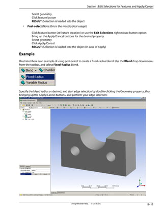
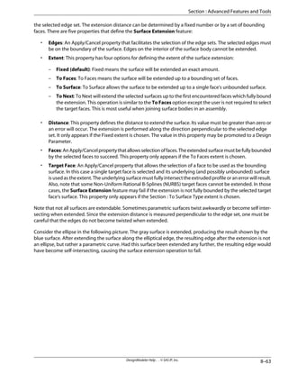
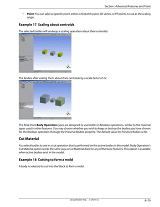
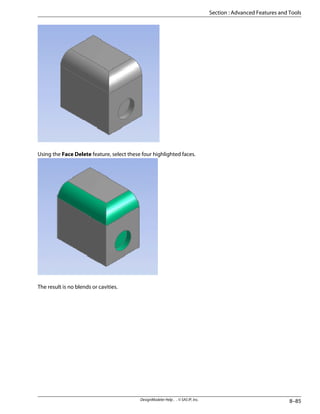
![Click Apply, to accept your selection, and then Section : Generate to create the Blend feature. Now, assume more
modeling has been done, and after some other features have been created, you want to go back and edit the
above edge selection. Use the right mouse button context menu over the Blend feature…
…and select the Edit Selections option. This will “roll back” the model to the state before the Blend feature.
Upon selecting the Edit Selections option, the model will roll back to the state it was in when the feature was
created. During selection editing, features that are inactive are shown in gray. If a feature was suppressed when
Edit Selections is selected, the feature and any of its parent features will become unsuppressed.
At this point, you may edit, say, the Blend feature's edge selection by double-clicking the Geometry property,
thus, again, bringing up the Apply/Cancel buttons, and perform your edge selection:
The current geometry selection of the feature is selected on screen. Now, say, add another edge to the selection
by holding down the [Ctrl] key:
DesignModeler Help . . © SAS IP, Inc.
8–12
3D Modeling](https://image.slidesharecdn.com/ansysworkbench-221030093541-da346bf2/85/ANSYS-Workbench-pdf-192-320.jpg)
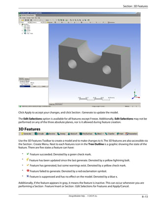
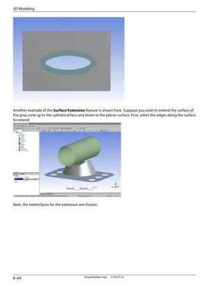
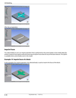
![Generate
Hotkey: [F5]
ClicktheGeneratebuttontoupdatethemodelafteranynumberofchangesinthemodel'sfeatureorsketch/plane
dimensions, or changes in design parameters.
Extrude
Use the Extrude button to create an extruded feature. Solids, surfaces, and thin-walled features can be created
from a sketch (to create surfaces, set the inner and outer thicknesses to zero). The active sketch is the default
input but can be changed by selecting the desired sketch or a plane from face (boundary used) in the Tree
Outline.
A Section : Named Selection can also be selected as the base object. If a Section : Named Selection is used, then
a Direction Vector must be defined, and will be used for extruding all legitimate items in the Section : Named
Selection. Extrude can use faces (its edges are actually used) and edges from the Section : Named Selection as
well as Surface Bodies (treated like faces) and Line Bodies (treated like edges) from Named Selections. Open sets
of edges will only be used if there are no faces or closed sets of edges in the Section : Named Selection.
The Details View is used to set the Extrude depth, direction vector, direction, direction type and modeling oper-
ation (Add, Cut, Slice, Imprint, or Add Frozen). Clicking Section : Generate completes the feature creation and
updates the model.
Direction Vector for Extrude
The default Direction Vector is normal to the plane the sketch lies in. However, you can define a custom Direction
Vector by selecting a Section : Direction Reference. The direction you choose must not be parallel to the base
object or the Extrude may fail to generate.
Note — The Direction Vector is required if the base object is a Section : Named Selection.
Direction Property for Extrude
You can access two directions via a combination box with four options:
Normal: Extrudes in positive Z direction of base object.
Reversed: Extrudes in negative Z direction of base object.
Both - Symmetric: Applies feature in both directions. One set of extents and depths will apply to both direc-
tions.
Both-Asymmetric:Appliesfeatureinbothdirections.Eachdirectionhasitsownextentanddepthproperties.
Extent Types:
There are five Extent Types that you use to define the extrusion:
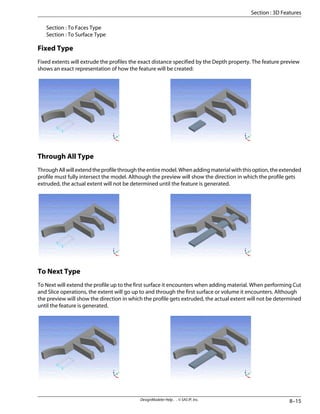
Section : Fixed Type
Section : Through All Type
Section : To Next Type
DesignModeler Help . . © SAS IP, Inc.
8–14
3D Modeling](https://image.slidesharecdn.com/ansysworkbench-221030093541-da346bf2/85/ANSYS-Workbench-pdf-194-320.jpg)
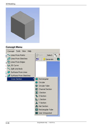
![window when viewing a cross section. DesignModeler will enter a dimension moving state, identical to the tool
used to move dimensions in the Section : Dimensions Toolbox in Sketching Mode. When you are done moving
dimensions on the cross section, the Move Dimensions state is ended by clicking on another item in the Tree
Outline or by clicking the Section : New Selection button.
Note that for Section : User Integrated cross sections, the Move Dimensions option does not appear because
there is no sketch representation for cross sections of this type.
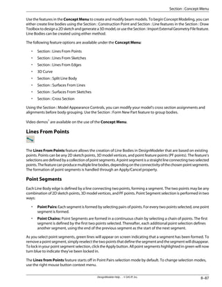
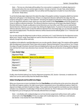
Cross Section Assignment
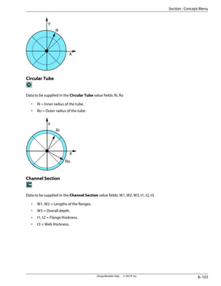
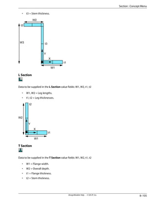
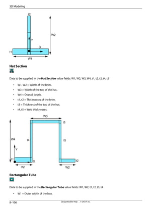
To assign a cross section to a line body, first select the line body in the TreeOutline. In the Details View will appear
a Cross Section property. At first, all line bodies will have no cross sections until you assign them. When a line
body has no cross section assigned to it, the Cross Section property will appear in yellow as “Not Selected.” Next
select the cross section to be assigned to the selected line body from the drop-down menu available in the Details
View. The drop-down menu will display all the cross section nodes added to the Tree Outline.
Note that the check mark on a line body will be yellow if no Cross Section is assigned or if a default alignment is
being used. The check mark will be red if the alignment is invalid.
To make cross section assignment faster, you can also assign cross sections to multiple bodies at once. By using
the [Ctrl] key or by using box selection, you can select multiple line bodies. In the Details View, you will see the
number of line bodies selected at the top of the property group. Though the properties shown are specific to
the first line body selected, the cross section assignment will apply to all selected bodies. Below is an example
of what you would see when four line bodies are selected.
8–97
DesignModeler Help . . © SAS IP, Inc.
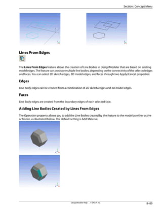
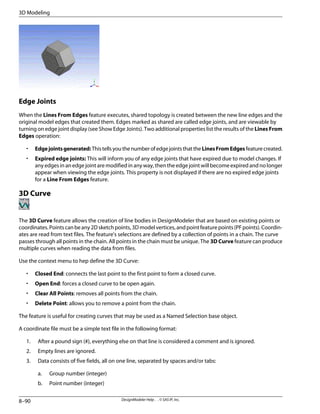
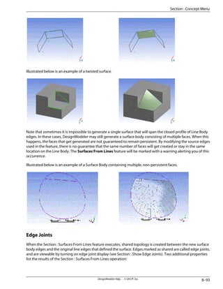
Section : Concept Menu](https://image.slidesharecdn.com/ansysworkbench-221030093541-da346bf2/85/ANSYS-Workbench-pdf-277-320.jpg)
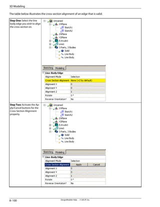
![Step Three: Select the de-
sired direction reference by
clicking in the Tree Outline
or graphics window.
Step Four: Click the Apply
button to lock in your choice.
To make cross section alignment faster, you can also assign direction references to multiple edges at once. By
using the [Ctrl] key or by using box selection, you can select multiple line body edges. In the Details View, you
will see the number of line body edges selected at the top of the property group. Though the properties shown
8–101
DesignModeler Help . . © SAS IP, Inc.
Section : Concept Menu](https://image.slidesharecdn.com/ansysworkbench-221030093541-da346bf2/85/ANSYS-Workbench-pdf-281-320.jpg)


![Once you have created Design Parameters to define your model, varying them is easy. Just change the Design
Parameter values in the first text window, then click the Check window tab to verify your changes. Note that
any features that are affected by the Design Parameter change will be marked as updated. Click Generate to
update the model.
Parameters Tutorial
The basic steps used in adding Design Parameters to a model in DesignModeler are illustrated in Section :
Process for Creating A Model.
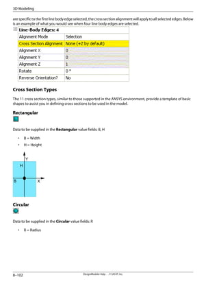
Parametric Expressions
Parametric expressions involve operations among parameters and numbers such as addition, subtraction, mul-
tiplication, and division. The available parametric expressions for DesignModeler are listed in the table below.
Operation
Operator
Addition
+
Subtraction
—
Multiplication
*
Division
/
Exponentiation
^
Modulus; returns the remainder of x/y.
%
Scientific notation
E+, E-, e+, e-
Parentheses can also be used for clarity and for nesting operations. The order in which DesignModeler evaluates
an expression is as follows:
1. Operations in parentheses (innermost first)
2. Scientific Notation (in order from left to right)
3. Exponentiation (in order from right to left)
4. Multiplication, Division, and Modulus (in order from left to right)
5. Unary association (such as +A or -A)
6. Addition and Subtraction (in order from left to right)
7. Logical Evaluation (in order from left to right)
Note — + or - must follow e/E in Parameter/Dimension Assignments tab but + need not follow e/E in
Design Parameters tab as it is implied.
Example 2 Parametric Expressions
X = A+B
P = (R1+R2)/2
D = B+E^2-4*A*C [Evaluates to B + E2
- 4AC]
XYZ = A+B^2/C%R [Evaluates to A + ((B2
/C) % R)]
9–5
DesignModeler Help . . © SAS IP, Inc.
Section : Parametric Expressions](https://image.slidesharecdn.com/ansysworkbench-221030093541-da346bf2/85/ANSYS-Workbench-pdf-293-320.jpg)
![Ae+2 [Evaluates to A00.00] or AE-2 [Evaluates to 0.0A]
Parametric Functions
A parametric function is a sequence of operations that return a single value, such as SQRT(x), LN(x), or SIN(x). The
available functions for DesignModeler are listed in the table below.
Absolute value of x.
ABS(x)
Exponential of x (ex
).
EXP(x)
Natural log of x.
LN(x)
Square root of x.
SQRT(x)
Sine, Cosine, and Tangent of x in degrees by default.
SIN(x)
COS(x)
TAN(x)
Arcsine, Arccosine, and Arctangent of x. x must be between
-1.0 and +1.0 for ASIN and ACOS. Output is in degrees by de-
fault. Range of output is -90 to +90 for ASIN and ATAN, and
0 to 180 for ACOS.
ASIN(x)
ACOS(x)
ATAN(x)
Example 3 Parametric Functions
A = acos (-1) # Evaluates to -90
B = abs (x) # Evaluates to |x|
C = asin (sqrt (2) / 2)) # Evaluates to 45
D = exp(ln(x)) # Evaluates to x
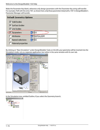
Sending Parameters to Simulation
When using .agdb files in Simulation, the entries in the Design Parameters text window appear as the CAD
parameters in Simulation if their names contain the Parameter Key defined before starting the simulation. Most
often, the Parameter Key is DS (default).
To send all Design Parameters to Simulation, make the Parameter Key blank before starting the simulation.
NotethatthisshouldnotbeconfusedwiththeParameterKeypropertyusedinSection:ImportExternalGeometry
File and Section : Attach to Active CAD Geometry features accessible via the Section : File Menu.
Note that when importing CAD models into DesignModeler, you can promote those CAD parameters to be
Design Parameters in DesignModeler. However, if a CAD system contains multiple parameters with the same
name, then only one of them can be promoted in DesignModeler.
DesignModeler Help . . © SAS IP, Inc.
9–6
Parameters](https://image.slidesharecdn.com/ansysworkbench-221030093541-da346bf2/85/ANSYS-Workbench-pdf-294-320.jpg)


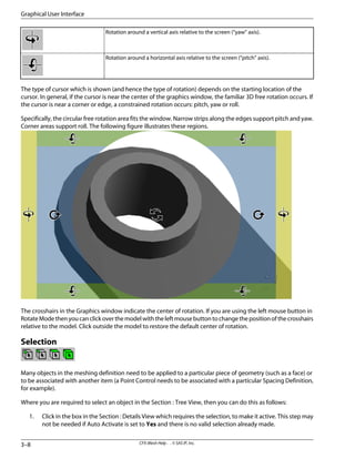
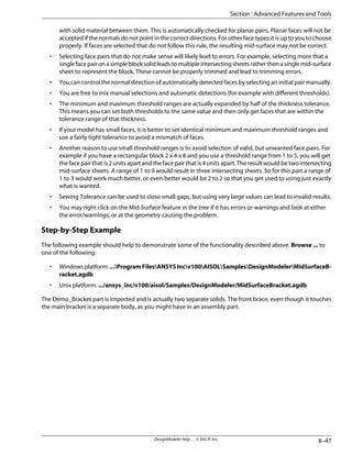
![the third). You must not enter the units string (such as “[mm]”); CFX-Mesh will add that in for itself using
the model dimensions. Press Return on the keyboard to finish editing the coordinates.
Selection Mode Toolbar, Box Select and Flood Select
or
There are two selection modes. To switch between them, you use the Selection Mode Toolbar, which is located
along with the rest of the toolbars at the top of the window.
•
Flood Select - In this mode, you can select multiple geometric objects simply by pressing and
holding down the left mouse button and then moving the mouse over them. Any object which the mouse
touches is added to the selection.
•
Box Select - In this mode, you can select geometric objects from the Graphics window by clicking
with the left mouse button and then dragging it across other objects. All the objects that the box fully
enclosesareselected.IfyouholddowntheCtrlkeywhileyoudrawthebox,thentheseitemswillbeadded
to the current selection.
Note that with both selection methods, hidden faces or hidden bodies cannot be selected. The faces or bodies
must be made visible in the model view in order that they can be selected.
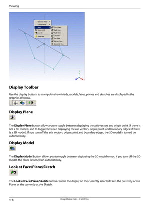
Display Toolbar
The Display Toolbar controls what is visible in the Graphics window.
Toggle the display of the Section : Triad.
Display Triad
Toggle the display of the Section : Ruler.
Display Ruler
Triad
The Triad in the bottom right corner of the Graphics window shows the orientation of the model. It can also be
used to position the model in one of several pre-defined viewing positions:
• Click on one of the arrows along the axes to put the model into a view normal to that arrow.
• Click on the cyan ball to put the model into an isometric view.
Moving the mouse over the Triad identifies the axis (X, Y, Z) and direction (+/-) of the arrow, using tool tips.
Positive-direction arrows are labeled and color-coded. Negative direction arrows display only when you hover
3–11
CFX-Mesh Help . . © SAS IP, Inc.
Section : Toolbars and Icons](https://image.slidesharecdn.com/ansysworkbench-221030093541-da346bf2/85/ANSYS-Workbench-pdf-333-320.jpg)


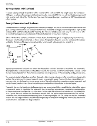
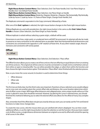
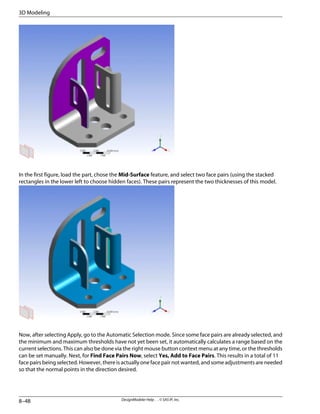
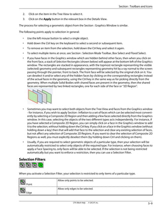
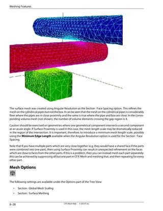
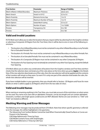
![To improve the parameterization of the surface, it may be necessary to regenerate the surface in the original
CAD package. To identify and fix poorly-parameterized surfaces, you need to understand how a surface is rep-
resented and how a mesh is created on the surface. One of the simplest examples is a unit cube. The six planar
surfaces which share common edges form a solid enclosing a volume of 1 unit cubed. Let us assume that the
edges of the cube are aligned with the three principle axes (X, Y, Z). The surface meshing algorithms implemented
in CFX-Mesh are, in effect, two-dimensional meshing algorithms, creating a group of connected planar triangles
for each individual planar surface of the cube. Each surface mesh is then mapped to the physical coordinates of
the geometry. For a unit cube it is relatively simple to see how this mapping takes place. The two-dimensional
coordinates map to each side of the cube, so ξ1 and ξ2 directly replace the x or y or z physical coordinates, as
shown in the table and diagram below.
Mapping (ξ1, ξ2) to (x, y, z)
Surface Location
(0, ξ1, ξ2)
Low X
(1, -ξ1, ξ2)
High X
(-ξ1, 0, ξ2)
Low Y
(ξ1, 1, ξ2)
High Y
(ξ1, ξ2, 0)
Low Z
(ξ1, -ξ2, 1)
High Z
The range of ξ1and ξ2 is [0,1] (for a parametric surface) and in the case of a unit cube the coordinates (x, y, z) also
have a range [0,1], so the mappings between ξ1, ξ2 and x, y, z are one-to-one. This is obviously not the case for
all surfaces and geometries, simply stretching the unit cube in the x-direction by scaling the geometry using the
vector (3,1,1) immediately changes the mapping between ξ1, ξ2 and the x-coordinate. This implies that there is
a direct relationship between the parametric and physical coordinates for a surface and that we need to consider
thelinearityofthemappingbetweenthetwocoordinatesystems.Thisisparticularlytrueinthecaseofparametric
surfaces where we mesh a unit square in parametric space which is mapped to the related geometrical surface.
The following examples demonstrate particular problems:
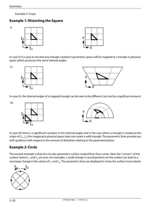
Example 1: Distorting the Square
Example 2: Circle
Example 3: Uneven Parametric Lines
Example 4: Degenerate Surfaces
5–19
CFX-Mesh Help . . © SAS IP, Inc.
Section : Geometry Requirements](https://image.slidesharecdn.com/ansysworkbench-221030093541-da346bf2/85/ANSYS-Workbench-pdf-357-320.jpg)


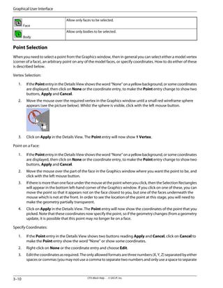
![You should never rename any of these files except by using the Project Page in ANSYS Workbench. If you need
to contact customer support then all of the files (except the .gtm) must be provided to allow your problem to
be reproduced.
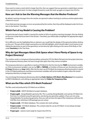
Valid and Invalid Values for Parameters, Locations and Names
Valid and Invalid Values
Valid and Invalid Locations
Valid and Invalid Names
Valid and Invalid Values
Most of the settings which require you to enter a number will only allow you to set numbers within a particular
range. This section lists the valid ranges, with some notes on the reason for the restriction.
Range of Validity
Parameter
Tree Section
0 to 100
Transparency (%)
Geometry
0 to 100
Shine (%)
Geometry
above zero
Short Edge Limit
Geometry>Verify Options
above 1.0
Sliver Factor Limit
Geometry>Verify Options
below 5% of the maximum extent of the
geometry
Short Edge Tolerance
Geometry>Fix Options
above zero
Maximum Spacing
Mesh>Spacing>Default Body Spacing
1.0 to 90.0
Angular Resolution [Degrees]
Mesh>Spacing>(Default) Face Spacing
below 50% of the maximum extent of
the geometry
Constant Edge Length
Mesh>Spacing>(Default) Face Spacing
1.00001 to 1.5
Expansion Factor
Mesh>Spacing>(Default) Face Spacing
below the maximum extent of the geo-
metry,abovetheMinimumEdgeLength
Maximum Edge Length
Mesh>Spacing>(Default) Face Spacing
below 5% of the maximum extent of the
geometry
Minimum Edge Length
Mesh>Spacing>(Default) Face Spacing
above zero
Radius of Influence
Mesh>Spacing>(Default) Face Spacing
0.000038 to 0.292 (corresponds to
between 360 and 4 edges round a circle
Relative Error
Mesh>Spacing>(Default) Face Spacing
1.00001 to 1.5
Expansion Factor
Mesh>Controls>Point Spacing
below 5% of the maximum extent of the
geometry
Length Scale
Mesh>Controls>Point Spacing
above zero
Radius of Influence
Mesh>Controls>Point Spacing
-360 to 360 degrees
Angle of Rotation
Mesh>Periodicity>Periodic Pair
any real number
Translation Along Axis (all three axes)
Mesh>Periodicity>Periodic Pair
1.00001 to 5.0
Expansion Factor
Mesh>Inflation
below 5% of the maximum extent of the
geometry
First Prism Height
Mesh>Inflation
0.0 to 40.0
Minimum Internal Angle
Mesh>Inflation
0.0 to 40.0
Minimum External Angle
Mesh>Inflation
1 to 50
Number of Inflated Layers
Mesh>Inflation
0 to 10
Number of Spreading Iterations
Mesh>Inflation
12–3
CFX-Mesh Help . . © SAS IP, Inc.
Section : Valid and Invalid Values for Parameters, Locations and Names](https://image.slidesharecdn.com/ansysworkbench-221030093541-da346bf2/85/ANSYS-Workbench-pdf-435-320.jpg)


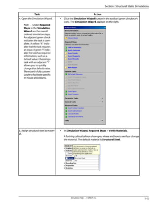
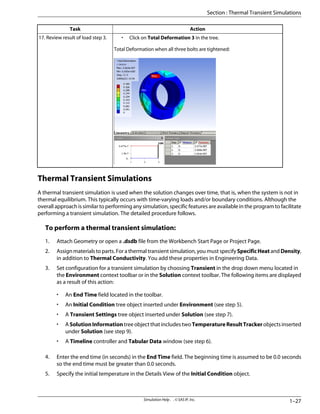
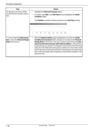
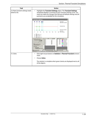
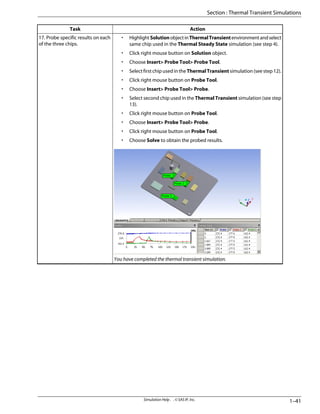
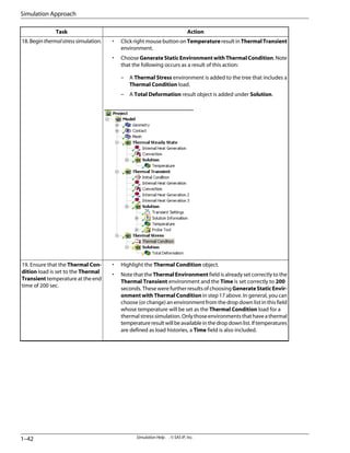
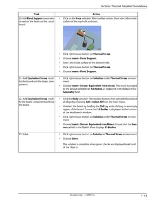
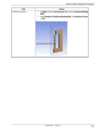
![Action
Task
• Click on the [Project tab] to leave DesignModeler and go to the Work-
bench Project Page.
• Click on New Simulation.
• After geometry appears in Simulation, ensure Units> Metric (m, kg, N,
°C, s, V, A) is checked.
Note — It is recommended that you save the Simulation database file
(dsdb) using File> Save As to save the file under another name and
in another location.
2.MovegeometryintoSimulation.
• Close the Simulation Wizard panel that is displayed on the right. We
will use the wizard in the next step.
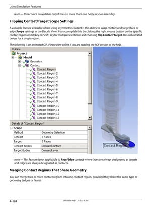
• In Outline, expand Contact folder (+).
• Select random ContactRegions. The individual regions are highlighted
in the assembly, as shown in the following animated demonstration.
The following is an animated GIF. Please view online if you are reading the
PDF version of the help.
• Collapse the Contact folder (-).
3. Examine contact regions in the
control arm assembly.
Uponimport,Simulationautomat-
ically detects and applies contact
conditions.
Simulation Help . . © SAS IP, Inc.
1–4
Simulation Approach](https://image.slidesharecdn.com/ansysworkbench-221030093541-da346bf2/85/ANSYS-Workbench-pdf-458-320.jpg)

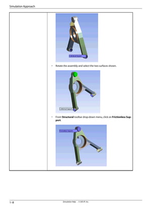
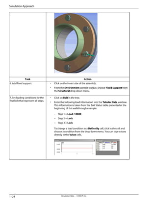
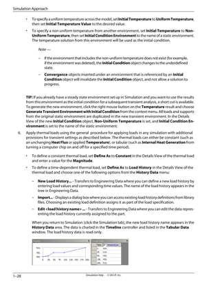
![• In Simulation Wizard, Required Steps = Insert Supports.
• Rotatetheassemblybyholdingdownmiddlemousebutton(orscrolling
wheel) so that the end cylinders are visible as shown.
• Select (click) the two end cylinders (use the [Ctrl] key for multiple selec-
tion).
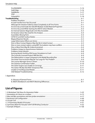
• From Structural toolbar drop-down menu (at callout balloon), click on
Cylindrical Support.
Note — You can also add loads and supports by using a right
mouse button click on the Environment folder in the Outline,
and choosing Insert > load or support from the context menu.
• Under Details of “Cylindrical Support”, set Tangential = Free. This
allows free rotation of the end cylinders in the tangential direction.
1–7
Simulation Help . . © SAS IP, Inc.
Section : Structural Static Simulations](https://image.slidesharecdn.com/ansysworkbench-221030093541-da346bf2/85/ANSYS-Workbench-pdf-461-320.jpg)
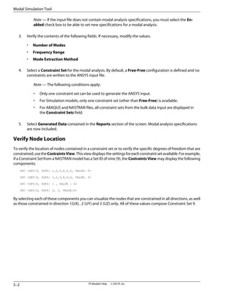
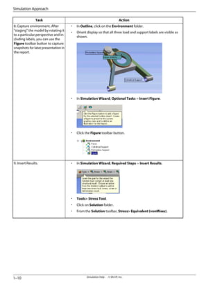
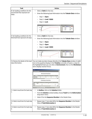
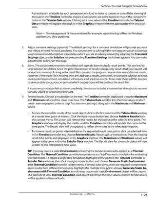
![Action
Task
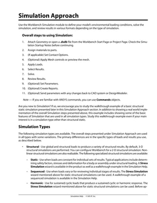
• In Simulation Wizard, Required Steps = Insert Loads.
• Reorient the assembly and select the face as shown.
• From Structural toolbar drop-down menu (at callout balloon), click on
Force.
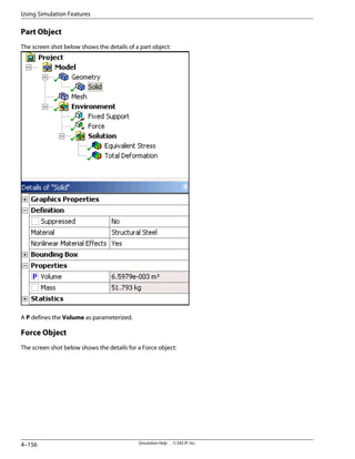
• Under Details of “Force”, set the following:
– Define By = Components.
– Z Component = -4450.
• [Enter].
7. Insert load.
1–9
Simulation Help . . © SAS IP, Inc.
Section : Structural Static Simulations](https://image.slidesharecdn.com/ansysworkbench-221030093541-da346bf2/85/ANSYS-Workbench-pdf-463-320.jpg)

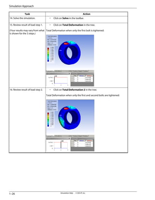
![Action
Task
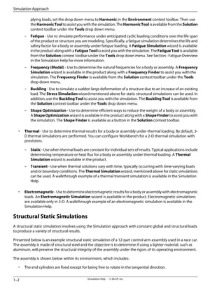
Browse ... to one of the following:
• Windows platform: ...Program FilesANSYS
Incv100AISOLSamplesSimulationBolts.agdb
• Unixplatform:.../ansys_inc/v100/aisol/Samples/Simulation/Bolts.ag-
db
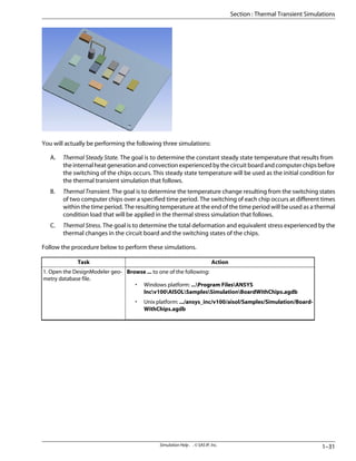
1. Open the DesignModeler geo-
metry database file.
• Click on the [Project tab] to leave DesignModeler and go to the Work-
bench Project Page.
• Click on New Simulation.
To match the layout in the picture above, click on the Rotate button in
the toolbar.
• Ensure Units> Metric (m, kg, N, °C, s, V, A) is checked.
Note — It is recommended that you save the Simulation database file
(dsdb) using File> Save As to save the file under another name and
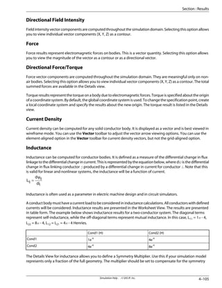
in another location.
2.MovegeometryintoSimulation.
• In Outline, click on the Environment folder.
• In the Environment context toolbar, type 3 in the Steps field and press
Enter.
3. Set configuration for a se-
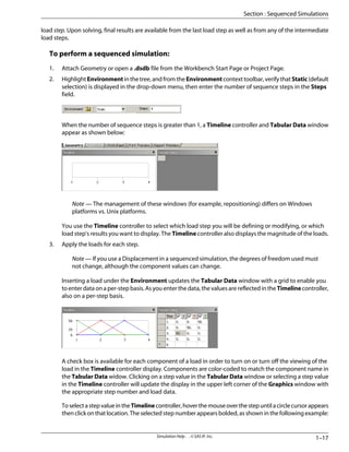
quenced simulation with 3 steps.
Simulation Help . . © SAS IP, Inc.
1–20
Simulation Approach](https://image.slidesharecdn.com/ansysworkbench-221030093541-da346bf2/85/ANSYS-Workbench-pdf-474-320.jpg)

![Action
Task
• Click on the [Project tab] to leave DesignModeler and go to the Work-
bench Project Page.
• Click on New Simulation.
• To match the layout in the picture above, click on the Rotate button in
the toolbar.
Note — It is recommended that you save the Simulation database file
(dsdb) using File> Save As, to save the file under another name and
in another location.
2.MovegeometryintoSimulation.
• Click right mouse button on Environment.
• Choose Rename.
• Type Thermal Steady State and press Enter.
• Ensure Units> Metric (m, kg, N, °C, s, V, A) is checked.
3. Begin thermalsteadystate simu-
lation.
Simulation Help . . © SAS IP, Inc.
1–32
Simulation Approach](https://image.slidesharecdn.com/ansysworkbench-221030093541-da346bf2/85/ANSYS-Workbench-pdf-486-320.jpg)
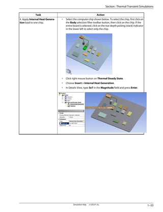
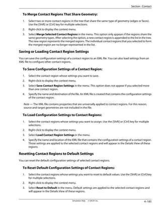
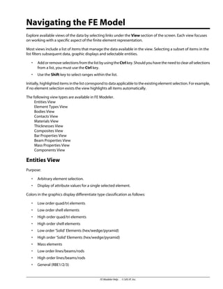
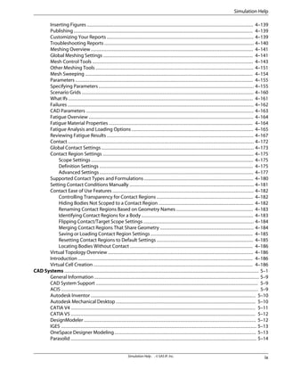
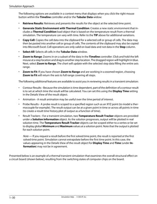
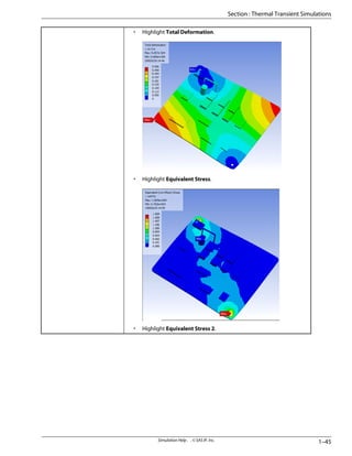
![Action
Task
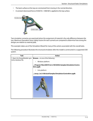
• Select the computer chip shown below.
• Click right mouse button on Thermal Transient.
• Choose Insert > Internal Heat Generation.
• In the Details View, set Define As to Load History.
• Click in History Data field and choose New Load History .... You are
transferred to Engineering Data.
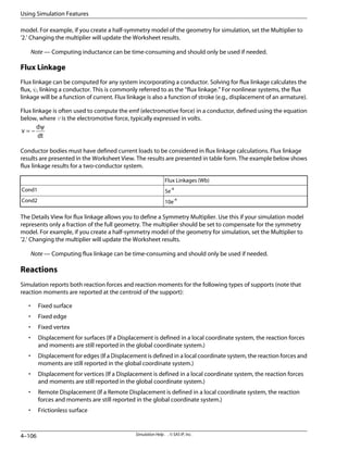
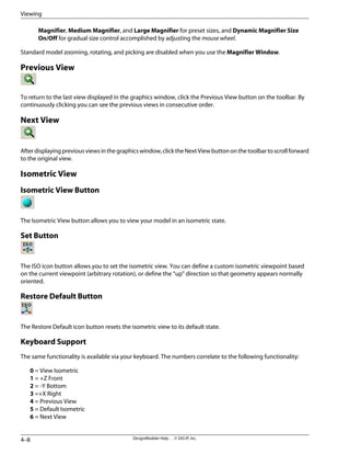
• Type the following data into the Heat Generation vs. Time table Click
in the first yellow field, type the data, then press the Enter key after each
entry.
– Time = 20; Heat Generation = 0
– Time = 20.1; Heat Generation = 5e7
– Time = 40; Heat Generation = 5e7
– Time = 40.1; Heat Generation = 0
• After pressing the Enter key followin entry of the last data point, click
the [Simulation] tab at the top to return to Simulation. Note that the
switching curve and data that you just defined are displayed in the
Timeline controller and Tabular Data windows.
12.AddInternalHeatGeneration
load to a chip such that the load
represents the following time his-
tory based on the switching states
of that chip:
0 - 20 sec. = Off
20 - 40 sec. = On
40 - 200 sec. = Off
1–37
Simulation Help . . © SAS IP, Inc.
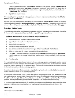
Section : Thermal Transient Simulations](https://image.slidesharecdn.com/ansysworkbench-221030093541-da346bf2/85/ANSYS-Workbench-pdf-491-320.jpg)
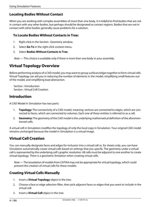
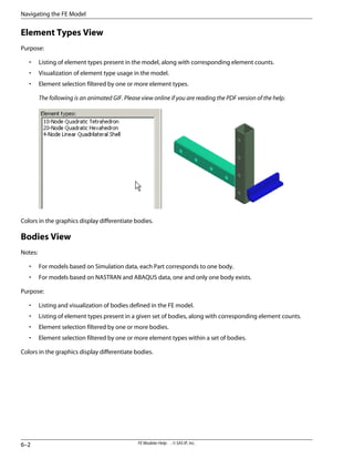
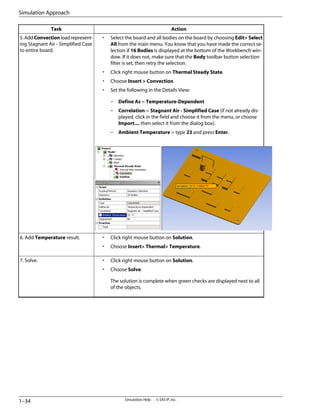
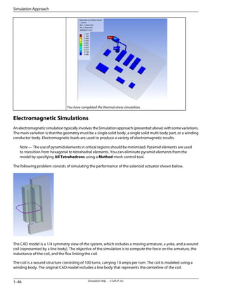
![Action
Task
• Select the computer chip shown below.
• Click right mouse button on Thermal Transient.
• Choose Insert > Internal Heat Generation.
• In the Details View, set Define As to Load History.
• Click in History Data field and choose New Load History .... You are
transferred to Engineering Data.
• Type the following data into the Heat Generation vs. Time table:
– Time = 60; Heat Generation = 0
– Time = 60.1; Heat Generation = 1e8
– Time = 70; Heat Generation = 1e8
– Time = 70.1; Heat Generation = 0
• Click the [Simulation] tab at the top to return to Simulation. Note that
the switching curve and data that you just defined are displayed in the
Timeline controller and Tabular Data windows.
13.AddInternalHeatGeneration
loadtoasecondchipsuchthatthe
load represents the following time
history based on the switching
states of that chip:
0 - 60 sec. = Off
60 - 70 sec. = On
70 - 200 sec. = Off
Simulation Help . . © SAS IP, Inc.
1–38
Simulation Approach](https://image.slidesharecdn.com/ansysworkbench-221030093541-da346bf2/85/ANSYS-Workbench-pdf-492-320.jpg)


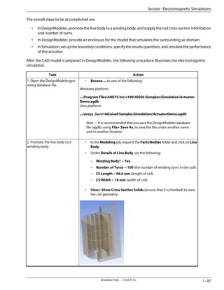

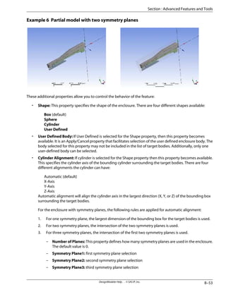
![• Tools> Enclosure.
• Under Details of Enclosure1, set the following:
– Shape = Box
– Number of Planes = 2 (for 2 symmetry planes).
– Symmetry Plane1: click on field, click ZXPlane in the Modeling
tab, then [Apply].
– Symmetry Plane2: click on field, click YZPlane in the Modeling
tab, then [Apply].
– Merge Parts? = Yes.
• [Generate].
1–49
Simulation Help . . © SAS IP, Inc.
Section : Electromagnetic Simulations](https://image.slidesharecdn.com/ansysworkbench-221030093541-da346bf2/85/ANSYS-Workbench-pdf-503-320.jpg)
![Action
Task
• Click on the [Project] tab to leave DesignModeler and go to the Work-
bench Project Page.
• Click on New Simulation.
• To match the layout in the picture above, click on the Rotate button in
the toolbar.
4.MovegeometryintoSimulation.
• In Outline, expand the Model folder, then expand the Geometry folder
down to the Part level, and click on armature.
• Under Details of “armature”, accept the default of Material = Struc-
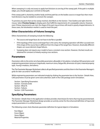
tural Steel.
5. Define material properties.
Simulation Help . . © SAS IP, Inc.
1–50
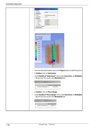
Simulation Approach](https://image.slidesharecdn.com/ansysworkbench-221030093541-da346bf2/85/ANSYS-Workbench-pdf-504-320.jpg)

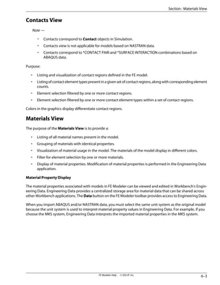
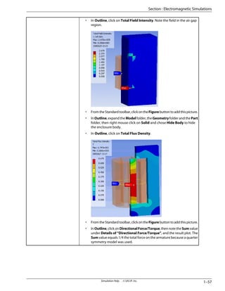
![Action
Task
• In Outline, click on the Solution folder.
• From Electromagnetic toolbar drop-down menu, click on Total Flux
Density.
• RepeataboveforTotalFieldIntensity,Inductance,FluxLinkage,and
Directional Force/Torque.
• Under Details of “Directional Force/Torque”, set Orientation = Y
Axis.
• From the Graphics Toolbar, click the Body selection button.
• Click on armature body in the Geometry window as shown below.
• In the Details View, click in the Geometry field, then click Apply.
9. Select solution results.
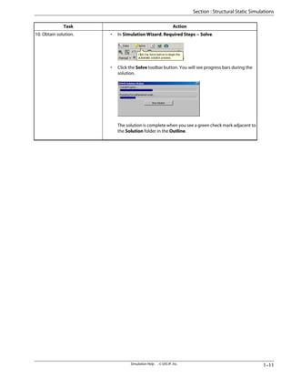
[Solve].
10. Obtain solution
1–55
Simulation Help . . © SAS IP, Inc.
Section : Electromagnetic Simulations](https://image.slidesharecdn.com/ansysworkbench-221030093541-da346bf2/85/ANSYS-Workbench-pdf-509-320.jpg)

![Action
Task
• Click on the Report Preview tab.
• Scroll down and click [Generate Report].
12. Create a report.
2-D Simulations
Simulation has a provision that allows you to run structural and thermal problems that are strictly two-dimen-
sional (2-D). For models and environments that involve negligible effects from a third dimension, running a 2-D
simulation can save processing time and conserve machine resources.
You can configure Workbench for a 2-D simulation by first creating or opening a surface model in DesignModeler,
or in any supported CAD system that has provisions for surface bodies (Autodesk Mechanical Desktop and
Autodesk Inventor do not support surface bodies). The model must be in the x-y plane. 2-D planar bodies are
supported, 2-D wire bodies are not. Then, on the Project Page, choose 2-D in the Analysis Type drop-down
menu located under Advanced Geometry Defaults, and attach the model into Simulation. You can specify a
2-D simulation only when you attach the model. After attaching, you cannot change from a 2-D simulation to a
3-D simulation or vice versa.
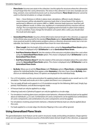
A 2-D simulation has the following characteristics:
• For Geometry items in the tree, you have the following choices located in the 2D Behavior field within
the Details View:
– Plane Stress (default): Assumes zero stress and non-zero strain in the z direction. Use this option for
structures where the z dimension is smaller than the x and y dimensions. Example uses are flat plates
subjected to in-plane loading, or thin disks under pressure or centrifugal loading. A Thickness field
is also available if you want to enter the thickness of the model.
– Axisymmetric: Assumes that a 3-D model and its loading can be generated by revolving a 2-D section
360o
about the y-axis. The axis of symmetry must coincide with the global y-axis. The geometry has
to lie on the positive x-axis of the x-y plane. The y direction is axial, the x direction is radial, and the z
direction is in the circumferential (hoop) direction. The hoop displacement is zero. Hoop strains and
stresses are usually very significant. Example uses are pressure vessels, straight pipes, and shafts.
Axisymmetric behavior cannot be used in a shape simulation.
1–59
Simulation Help . . © SAS IP, Inc.
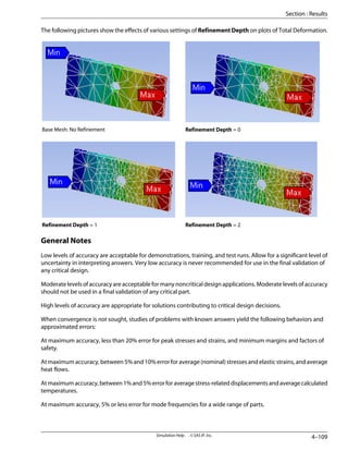
Section : 2-D Simulations](https://image.slidesharecdn.com/ansysworkbench-221030093541-da346bf2/85/ANSYS-Workbench-pdf-513-320.jpg)

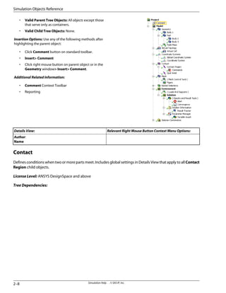


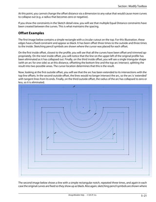
![• Valid Parent Tree Object: Solution Information
• Valid Child Tree Objects: Comment
Insertion Options: Use any of the following methods after
highlighting Solution Information object:
• Choose Result Tracker Deformation, or Contact,
or Temperature on Solution Information context
toolbar.
• Insert Solution Item Solution Information
Result Tracker Deformation, or Contact, or Tem-
perature
• Click right mouse button on Solution Information
objectorintheGeometrywindowInsertDeform-
ation, or Contact, or Temperature.
Additional Related Information:
• Result Tracker Objects
• Solution Options
• Solution Context Toolbar
Relevant Right Mouse Button Context Menu Options:
Details View:
Export - available in Worksheet tab view.
Rename Based on Definition
Scope:
Scoping Method - appears for a Temperature result
tracker object.
Geometry - appears for a Deformation result tracker
object, or for a Temperature object if Scoping Method
is set to Geometry Selection. Use selection filters to pick
geometry, click in the Geometry field, then click Apply.
Contact Region - appears for a Contact result tracker
object.
Definition:
Type - Read-only indication of result tracker type for De-
formationandTemperatureobjects.ForContactobject,
specify contact output.
Orientation - appears for a Deformation result tracker
object.
X-Axis Values - specify Time or Cumulative Iteration.
Results and Result Tools (Group)
Defines the engineering output for displaying and analyzing the results from a solution.
License Level: ANSYS DesignSpace and above.
Appliestothefollowingobjects: 1stBucklingMode, BeamTool, BiaxialityIndication, BucklingTool, Contact
Tool, Current Density, Damage, Damage Matrix, Direct Stress, Directional Deformation, Directional Field
Intensity, DirectionalFluxDensity, DirectionalForce/Torque, DirectionalHeatFlux, ElasticStrainIntensity,
Electric Potential, Equivalent Alternating Stress, Equivalent Plastic Strain, Equivalent Stress, Fatigue
Sensitivity, Fatigue Tool, Flux Linkage, Frequency Finder, Frequency Mode in Range [1st - 6th], Frequency
2–33
Simulation Help . . © SAS IP, Inc.
Section : Page Listings](https://image.slidesharecdn.com/ansysworkbench-221030093541-da346bf2/85/ANSYS-Workbench-pdf-555-320.jpg)
![Response, Frictional Stress, Gap, Harmonic Tool, Hysteresis, Inductance, Life, Maximum Bending Stress,
MaximumCombinedStress,MaximumPrincipalElasticStrain,MaximumPrincipalStress,MaximumShear
Elastic Strain, Maximum Shear Stress, Middle Principal Elastic Strain, Middle Principal Stress, Minimum
Bending Stress, Minimum Combined Stress, Minimum Principal Elastic Strain, Minimum Principal Stress,
Normal Elastic Strain, Normal Stress, Penetration, Phase Response, Pressure, Probe, Probe Tool, Rainflow
Matrix, Reactions, Safety Factor [fatigue], Safety Factor [stress], Safety Margin, Shape Finder, Shear Elastic
Strain, Shear Stress, Sliding Distance, Status, Stress Intensity, Stress Ratio, Stress Tool, Structural Error,
Temperature, Thermal Error, Thermal Strain, Total Deformation, Total Field Intensity, Total Flux Density,
Total Force, Total Heat Flux, Vector Principal Elastic Strain, Vector Principal Stress
Tree Dependencies:
Simulation Help . . © SAS IP, Inc.
2–34
Simulation Objects Reference](https://image.slidesharecdn.com/ansysworkbench-221030093541-da346bf2/85/ANSYS-Workbench-pdf-556-320.jpg)
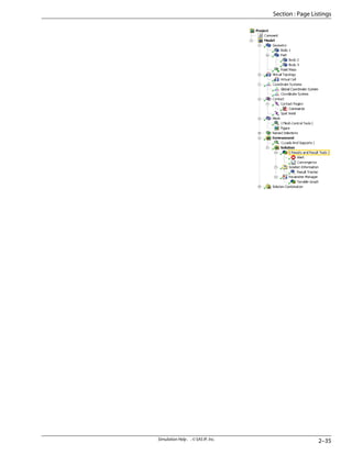
![• Valid Parent Tree Object:
– For Direct Stress, Maximum Bending Stress,
MaximumCombinedStress,MinimumBending
Stress, Minimum Combined Stress: Beam Tool
– For 1st Buckling Mode: Buckling Tool
– ForFrictionalStress,Gap,Penetration,Pressure,
Reactions,SlidingDistance,Status:ContactTool
– For Biaxiality Indication, Damage, Damage
Matrix, Equivalent Alternating Stress, Fatigue
Sensitivity, Hysteresis, Life, Rainflow Matrix,
Safety Factor [fatigue]: Fatigue Tool
– For Frequency Mode in Range [1st - 6th]: Fre-
quency Finder
– For FrequencyResponse, PhaseResponse: Har-
monic Tool
– For Safety Factor [stress], Safety Margin, Stress
Ratio: Stress Tool
– ForDirectionalDeformation,TotalDeformation:
Beam Tool, Buckling Tool, Frequency Finder,
Solution
– For all stress and strain result objects: Buckling
Tool, Frequency Finder, Solution
– For all other objects: Solution
• Valid Child Tree Objects:
– For Beam Tool: Comment, Direct Stress, Direc-
tionalDeformation,Figure,MaximumBending
Stress, Maximum Combined Stress, Minimum
Bending Stress, Minimum Combined Stress,
Total Deformation
– ForBucklingTool:1stBucklingMode,Comment,
all stress and strain result objects, Directional
Deformation, Figure, Total Deformation
– For Contact Tool: Comment, Figure, Frictional
Stress, Gap, Penetration, Pressure, Reactions,
Sliding Distance, Status
– For Fatigue Tool: Biaxiality Indication, Com-
ment, Damage, Damage Matrix, Equivalent Al-
ternatingStress,FatigueSensitivity,Hysteresis,
Life, Rainflow Matrix, Safety Factor [fatigue]
– For Frequency Finder: Comment, all stress and
strain result objects, Directional Deformation,
Frequency Mode in Range [1st - 6th], Figure,
Total Deformation
– ForHarmonicTool:FrequencyResponse,Phase
Response
– For StressTool: Comment, Figure, SafetyFactor
[stress], Safety Margin, Stress Ratio
Simulation Help . . © SAS IP, Inc.
2–36
Simulation Objects Reference](https://image.slidesharecdn.com/ansysworkbench-221030093541-da346bf2/85/ANSYS-Workbench-pdf-558-320.jpg)
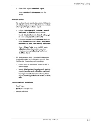
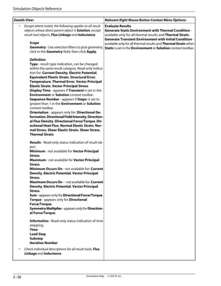
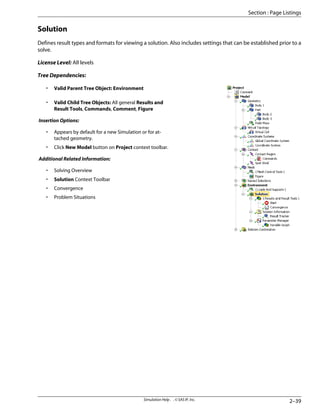

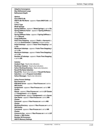
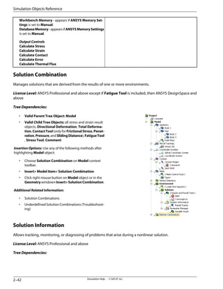
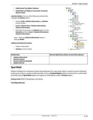
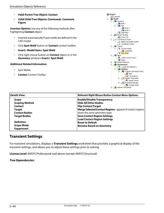
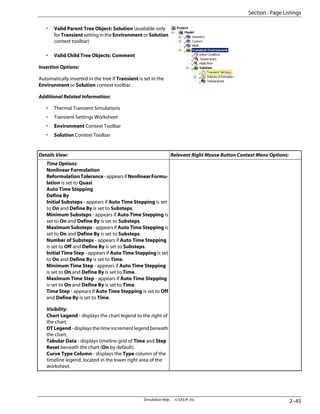
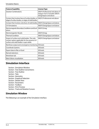
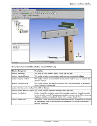
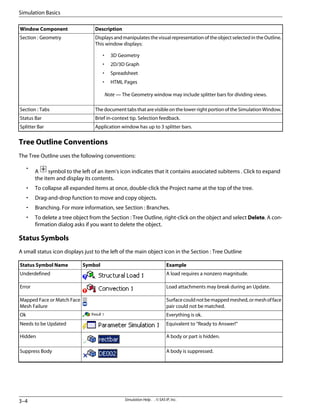
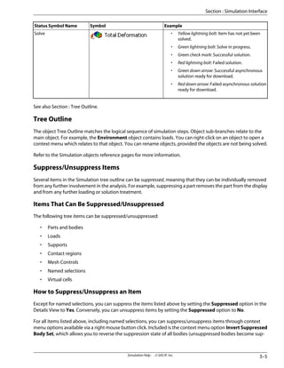
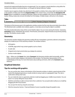
![• Use the stack of rectangles in the lower left corner of the Section : Geometry to select surfaces hidden by
your current selection.
• To rotate about a specific point in the model, switch to rotate mode and click the model to select a rotation
point. Click off the model to restore the default rotation point.
• To multi-select one or more surfaces, hold the [CTRL] key and click the surfaces you wish to select, or use
Box Select to select all surfaces within a box. The [CTRL] key can be used in combination with Box Select
to select surfaces within multiple boxes.
• Click the Viewports icon to view up to four images in the Section : Geometry window.
• Controls are different for Graphs Charts.
Rotation Cursors for Display
Pointer Modes
Defining Direction
Direction Defaults
Highlighting Geometry in Select Direction Mode
Selecting Direction by Surface
Selecting Direction Using the Section : Triad and Rotation Cursors
Highlighting
Picking
Blips
Painting
Depth Picking
Selection Filters
The Extend Selection Command
The Select Command
Viewports
Graph Chart Control
Rotation Cursors for Display
Activates rotational controls in the Geometry window (left mouse button). The cursor changes appearance
depending on its window location.
Pointer Modes
The pointer in the graphics window is always either in a picking filter mode or a view control mode. When in a
view control mode the selection set is locked. To resume the selection, repress a picking filter button.
The Graphics Toolbar offers several geometry filters and view controls as the default state, for example, surface,
edge, rotate, and zoom.
If a Geometry field in the Section : Details View has focus, inappropriate picking filters are automatically disabled.
For example, a pressure load can only be scoped to surfaces.
If the Direction field in the Section : Details View has focus, the only enabled picking filter is Select Direction.
SelectDirection mode is enabled for use when the Direction field has focus; you never choose SelectDirection
manually.Youmaymanipulatetheviewwhileselectingadirection.InthiscasetheSelectDirectionbuttonallows
you to resume your selection.
3–7
Simulation Help . . © SAS IP, Inc.
Section : Simulation Interface](https://image.slidesharecdn.com/ansysworkbench-221030093541-da346bf2/85/ANSYS-Workbench-pdf-577-320.jpg)
![Defining Direction
Orientation may be defined by any of the following geometric selections:
• A planar face (normal to).
• A straight edge.
• Cylindrical or revolved face (axis of).
• Two vertices.
If an axis is required (e.g. for rotational velocity) selection of a planar face also requires a vertex.
Alternatively, world (X, Y, Z) components may be used to define vector loads.
Direction Defaults
IfyoucreateanobjectbyselectingGeometryandchoosingInsert,theDirectionfieldmaydefaultifthegeometry
defines an orientation. For example, a force applied to a planar face by default acts normal to the face. One of
the two directions is chosen automatically. The load annotation displays the default direction.
Highlighting Geometry in Select Direction Mode
Unlike other picking filters (where one specific type of geometry highlights during selection) the SelectDirection
filter highlights any of the following during selection:
• Planar faces
• Straight edges
• Cylindrical or revolved faces
• Vertices
If one vertex is selected, you must hold down the [CTRL] key to select the other. When you press the [CTRL] key,
only vertices highlight.
Selecting Direction by Surface
The following figure shows the graphic display after choosing a surface to define a direction. The same display
appears if you edit the Direction field later.
• The selection blip indicates the hit point on the surface.
• Twoarrowsshowthepossibleorientations.TheyappearintheupperleftcorneroftheSection:Geometry.
If either arrow is clicked, the direction flips.
When you finish editing the direction, the hit point (initially marked by the selection blip) becomes the default
location for the annotation:
Simulation Help . . © SAS IP, Inc.
3–8
Simulation Basics](https://image.slidesharecdn.com/ansysworkbench-221030093541-da346bf2/85/ANSYS-Workbench-pdf-578-320.jpg)
![Note — The scope is indicated by painting the geometry.
Highlighting
Highlighting provides visual feedback about the current pointer behavior (e.g. select surfaces) and location of
the pointer (e.g. over a particular surface).
The surface edges are highlighted in colored dots.
Picking
A pick means a click on visible geometry. A pick becomes the current selection, replacing previous selections. A
pick in empty space clears the current selection.
Byholdingthe[CTRL]keydown,youcanaddunselecteditemstotheselectionandselecteditemscanberemoved
from the selection. Clicking in empty space with [CTRL] depressed does not clear current selections.
Blips
A crosshair blip appears at the location where you release the mouse button:
3–9
Simulation Help . . © SAS IP, Inc.
Section : Simulation Interface](https://image.slidesharecdn.com/ansysworkbench-221030093541-da346bf2/85/ANSYS-Workbench-pdf-579-320.jpg)
![A blip serves to:
• Mark a picked point on visible geometry.
• Represent a ray normal to the screen passing through all hidden geometry.
Note — This is important for depth picking, a feature discussed below.
Blips disappear when you clear the selection or make another pick.
Painting
Painting means dragging the mouse on visible geometry to select more than one entity. A pick is a trivial case
of painting. Without holding the [CTRL] key down, painting picks all appropriate geometry touched by the
pointer.
Depth Picking
Depth Picking allows you to pick geometry through the Z-order behind the blip.
Whenever a blip appears above a selection, the graphics window displays a stack of rectangles in the lower left
corner. The rectangles are stacked in appearance, with the topmost rectangle representing the visible (selected)
geometry and subsequent rectangles representing geometry hit by a ray normal to the screen passing through
the blip, front to back. The stack of rectangles is an alternative graphical display for the selectable geometry.
Each rectangle is drawn using the same edge and surface colors as its associated geometry.
Highlighting and picking behaviors are identical and synchronized for geometry and its associated rectangle.
Moving the pointer over a rectangle highlights both the rectangle its geometry, and vice versa. [CTRL] key and
paintingbehaviorsarealsoidenticalforthestack.Holdingthe[CTRL]keywhileclickingrectanglespicksorunpicks
associated geometry. Dragging the mouse (Painting) along the rectangles picks geometry front-to-back or back-
to-front.
Selection Filters
The mouse pointer in the graphics window is either in a picking filter mode or a view control mode. A latched
button in the graphics toolbar indicates the current mode.
Simulation Help . . © SAS IP, Inc.
3–10
Simulation Basics](https://image.slidesharecdn.com/ansysworkbench-221030093541-da346bf2/85/ANSYS-Workbench-pdf-580-320.jpg)
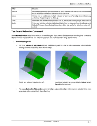
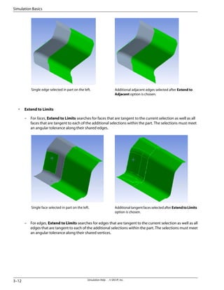
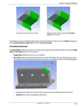
![– Dragging to the left to form the box selects all entities that touch the box.
– Visual cue: 4 tick marks that cross the sides of the box.
You can use the [CTRL] key for multiple selections in both modes.
Viewports
The Viewports toolbar button allows you to split the graphics display into a maximum of four simultaneous
views. You can see multiple viewports in the Section : Geometry window when any object in the tree is in focus
except Project. You can choose one, horizontal, vertical, or four viewports. Each viewport can have separate
camera angles, labels, titles, backgrounds, etc. Any action performed when viewports are selected will occur
only to the active viewport. For example, if you animate a viewport, only the active viewport will be animated,
and not the others.
A figure can be viewed in a single viewport only. If multiple viewports are created with the figure in focus, all
other viewports display the parent of the figure.
Note — Each viewport has a separate Slice tool, and therefore separate Draw Slice Plane. The concept
of copying a Slice Plane from one window to the next does not exist. If you want Slice Planes in a new
window, you must create them in that window.
Viewports are not supported in sequenced simulations.
Simulation Help . . © SAS IP, Inc.
3–14
Simulation Basics](https://image.slidesharecdn.com/ansysworkbench-221030093541-da346bf2/85/ANSYS-Workbench-pdf-584-320.jpg)
![Graph Chart Control
The following controls are available for Graphs/Charts in these areas: Section : Convergence, Parameter Manager
Variable Graphs, and Section : Fatigue Overview result items.
Control
Feature
[Right Mouse Button]
Pan
[Middle Mouse Button]
Zoom
[[Alt]Left Mouse Button]
Box Zoom
[Left Mouse Button]
Rotate (3D only)
[[Shift]Left Mouse Button]
Perspective Angle (3D only)
[[Ctrl]Left Mouse Button] along graph line
Display Coordinates (2D only)
Tips for working with graphs and charts:
• Some features are not available for certain graphs.
• Zoom will zoom to or away from the center of the graph. Pan so that your intended point of focus is in
the center prior to zooming.
• If the graph has a Pan/Zoom control box, this can be used to zoom (shrink box) or pan (drag box).
• Double-clicking the Pan/Zoom control box will return it to its maximum size.
Details View
The Details View is located in the bottom left corner of the window. It provides you with information and details
that pertain to the object selected in the Section : Tree Outline. Some selections require you to input information
(e.g., force values, pressures). Some selections are drop-down dialogs, which allow you to select a choice. Fields
may be grayed out. These cannot be modified.
The following example illustrates the Details View for the object called Geometry.
3–15
Simulation Help . . © SAS IP, Inc.
Section : Simulation Interface](https://image.slidesharecdn.com/ansysworkbench-221030093541-da346bf2/85/ANSYS-Workbench-pdf-585-320.jpg)
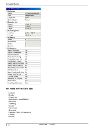
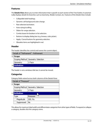
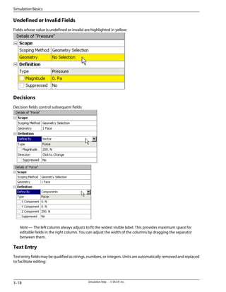
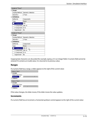
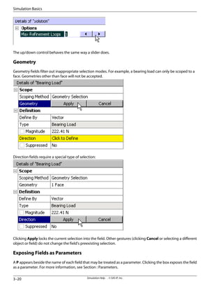
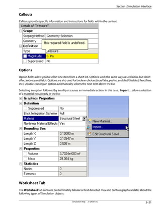
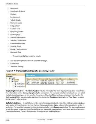
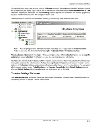
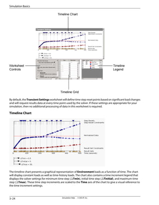
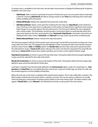
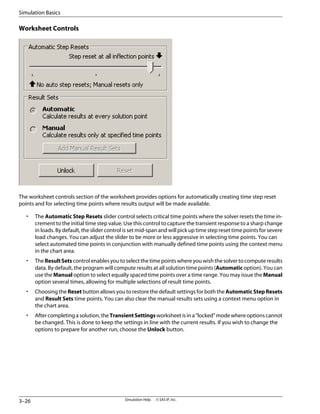
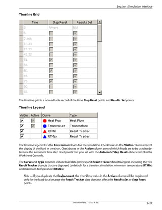
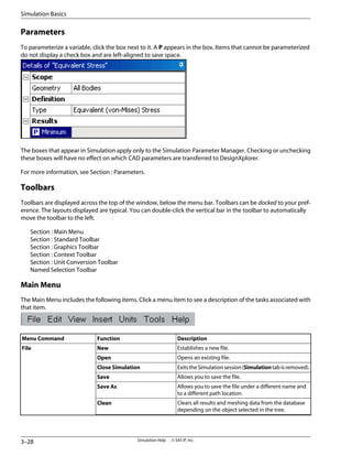
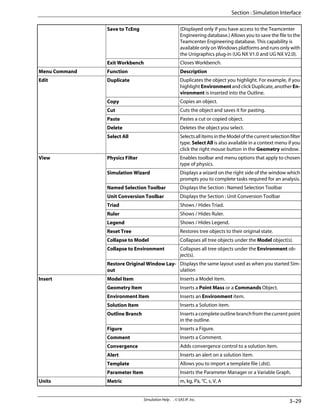
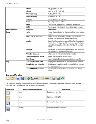
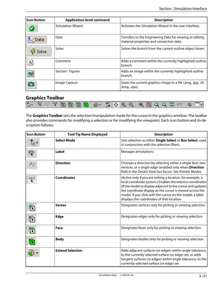
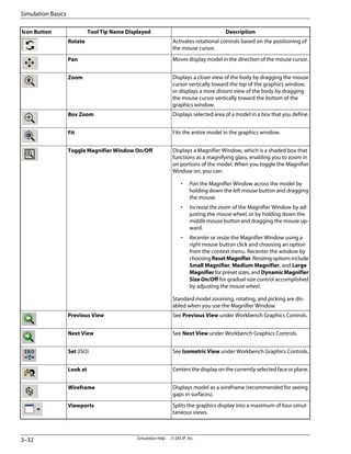
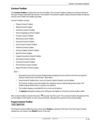
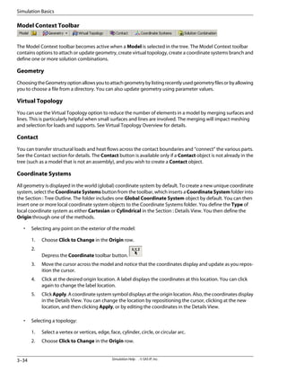
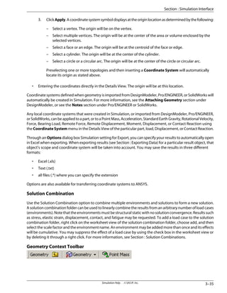
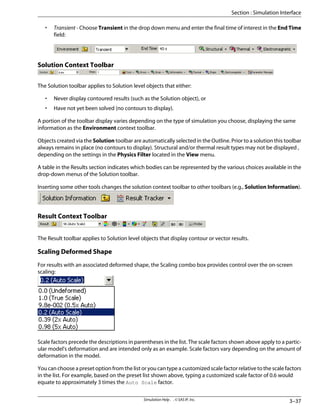
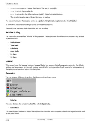
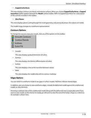
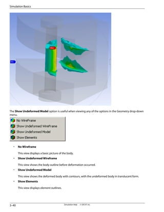
![Vectory Display Context Toolbar
Using the Graphics button, you can display results as vectors with various options for controlling the display.
• ClicktheGraphicsbuttonontheResultcontexttoolbartoconverttheresultdisplayfromcontours(default)
to vectors.
• When in vector display, a Vector Display toolbar appears with controls as described below.
Displays vector length proportional to the magnitude of the
result.
Displays a uniform vector length, useful for identifying vector
paths.
Controls the relative length of the vectors in incremental steps
from 1 to 10 (default = 5), as displayed in the tool tip when you
drag the mouse cursor on the slider handle.
Displays all vectors, aligned with each element.
Displays vectors, aligned on an approximate grid.
Controls the relative size of the grid, which determines the
quantity (density) of the vectors. The control is in uniform steps
from 0 [coarse] to 100 [fine] (default = 20), as displayed in the
tool tip when you drag the mouse cursor on the slider handle.
Note — This slider control is active only when the adja-
cent button is chosen for displaying vectors that are
aligned with a grid.
Displays vector arrows in line form.
Displays vector arrows in solid form.
• When in vector display, click the Graphics button on the Result context toolbar to change the result
display back to contours. The Vector Display toolbar is removed.
Presented below are examples of vector result displays.
3–41
Simulation Help . . © SAS IP, Inc.
Section : Simulation Interface](https://image.slidesharecdn.com/ansysworkbench-221030093541-da346bf2/85/ANSYS-Workbench-pdf-611-320.jpg)
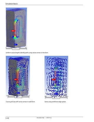
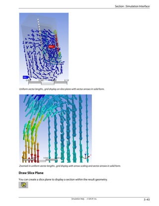
![• Click the toolbar button and then drag the mouse across the part to create the Slice Plane. To view the
newly created plane, rotate the model.
• You can construct additional Slice Planes by clicking and dragging additional lines across the model.
• To exit Draw Slice Plane mode, click the toolbar button again.
Edit Planes
You can use the Edit Planes toolbar button to display Slice Plane anchors.
• Click on the line on either side of the anchor to view the colored exterior on that side of the plane. This is
called a “Capping Plane.” A dashed line indicates a Slice Place, a solid line denotes a Capping Plane. You
cannot display a Slice Plane within a Capping Plane.
• Drag the Slice Plane or Capping Plane anchor to change the position of the plane.
• To maneuver between multiple planes, press the TAB key. You can also mouse over the square selection
boxes.TheactiveSlicePlaneorCappingPlanedisplaysablueboxwithintheanchor.Inactiveplanesdisplay
a white box. Locate the desired box and click to select. When your mouse is over a box, it turns red.
• To delete the selected Slice Plane or Capping Plane, press the [Delete] key. If you delete all of the planes,
you'll be left with a wireframe model (you can then click the Geometry drop-down menu and select Ex-
terior, or add new Slice Planes if you wish).
• To exit Edit Planes Mode, click the toolbar button again.
Usage Tip: To more fully grasp the new features of planes, you can experiment using different models.
Simulation Help . . © SAS IP, Inc.
3–44
Simulation Basics](https://image.slidesharecdn.com/ansysworkbench-221030093541-da346bf2/85/ANSYS-Workbench-pdf-614-320.jpg)