This document contains worked solutions to three hydraulics problems. In problem 1, the author calculates flow rates and forces in a channel. They find a flow rate of 58.8 m/s and a force of 538 N. Problem 2 involves calculating velocities and pressures in a siphon, finding velocities of 7.67 m/s and a gauge pressure of -54.9 kPa. For part b, they calculate the exit level is 25.8 m below the surface. Problem 3 parts a and b involve calculating flow rates in pipes, finding rates of 71.6 L/s and 0.05 m3/s respectively, and the head required by a pump of 61.6 m.
![Hydraulics 2 Coursework 1 David Apsley
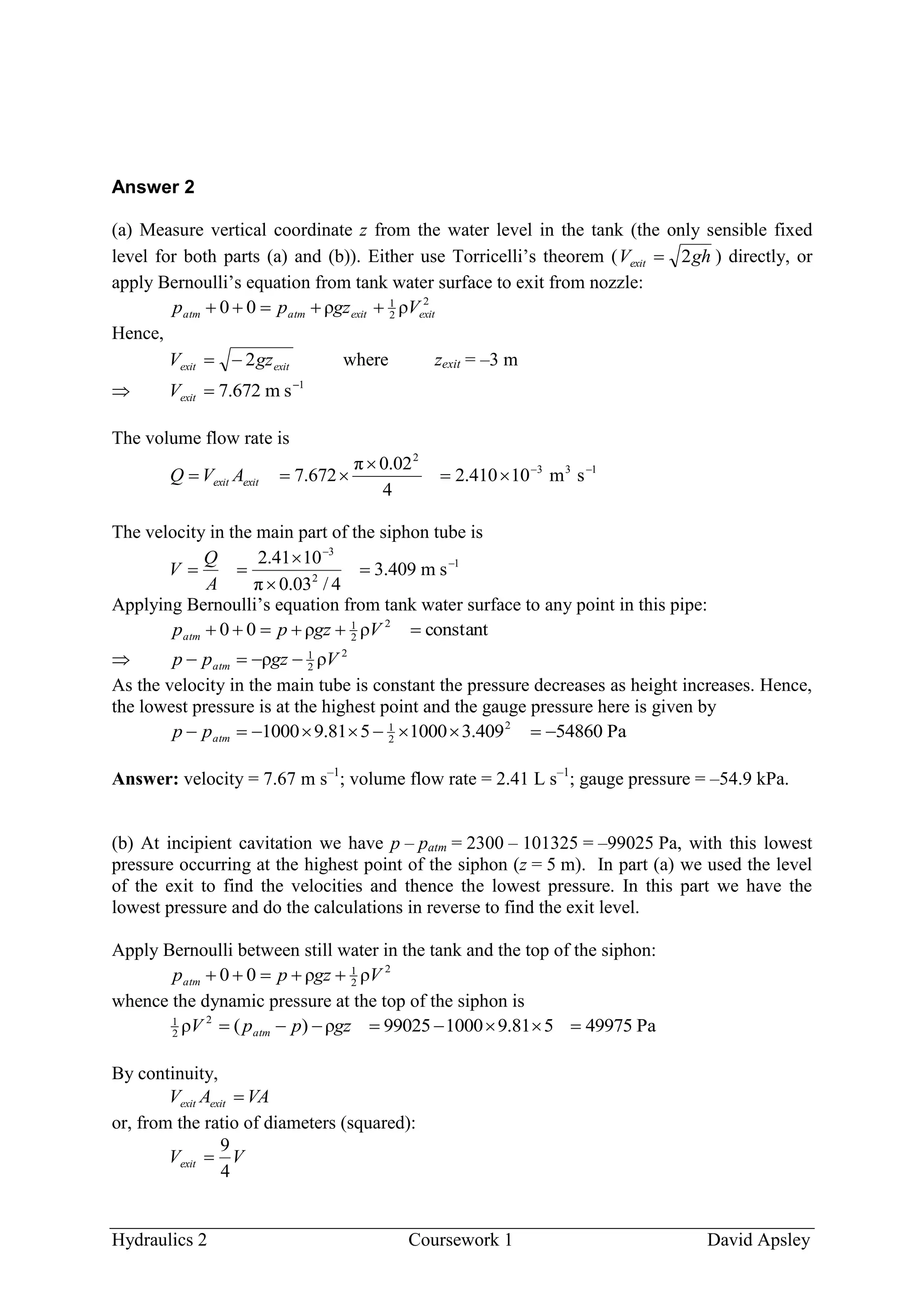
Answer 1
(a) By continuity between sections A and B the flow per unit width is (in metre-second units):
50.23
)]1ln[cosh(1.0)]3ln[cosh(1.04.040
)]110ln[cosh(
10
1
40
d)]110tanh(1[404.0
4.0
0
4.0
0
yy
yyUq A
1
sm75.58
4.0
50.23
AU
Answer: UA = 58.8 m s–1
.
(b) From the steady-state momentum principle, per unit width:
4.0ρd)]110tanh(1[)40(ρ4.0)( 2
4.0
0
22
ABA UyyFpp (*)
The integral is
4.0
0
2
d)]110(tanh)110tanh(21[ yyyI
or, using θsech1θtanh 22
,
9994.0
))1tanh(3(tanh1.0)]1ln[cosh()]3ln[cosh(2.08.0
)110tanh(
10
1
)110cosh(ln
10
2
2
d)]110(sech)110tanh(22[
4.0
0
4.0
0
2
yyy
yyyI
Substituting in (*):
4.076.582.19994.0402.14.02000 22
F
N5.538F
Answer: force = 538 N.
(c) Note that, as there is an upstream boundary layer due to the lower wall and an adverse
pressure gradient due to high-pressure upstream of the spar, there is separation and
recirculation upstream as well as downstream.](https://image.slidesharecdn.com/ans1-200221065013/75/Ans1-1-2048.jpg)