Downloaded 119 times


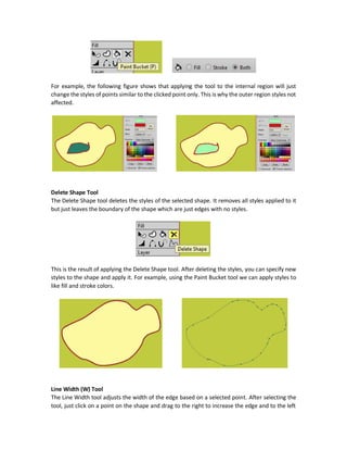
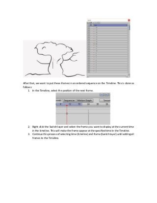
![ Anime Studio Pro 10 Layers
o Bone
Understanding Anime Studio Bones
Creating Bone Layers
Add Vector Layer to Bone Layer
Understanding the Bone Layer Bone Tools
Select Bone (B)
o Bone Selection
Bones Dropdown Menu
Rectangle
Lasso
Shift Key
o Bone Color
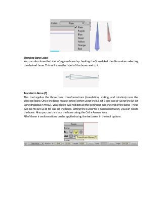
o Showing Bone Label
o Bone Constraints
Angle Constraints
Target
Add Bone (A) [Adding Bones in Bone Layers]
o Bone Starting and End Points
o Parent-Child Relationship
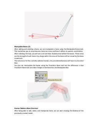
Transform Bone (T)
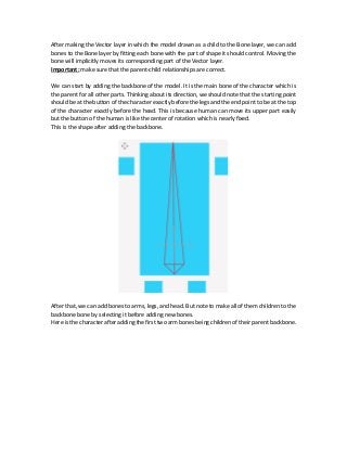
Manipulate Bones (Z)
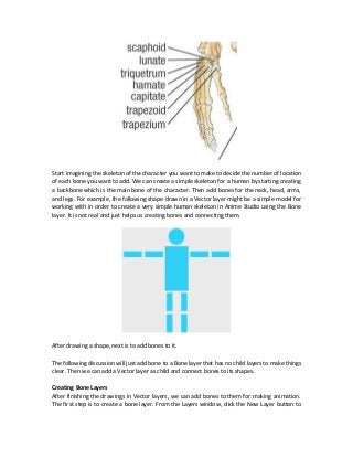
Human Skeleton Bone Structure
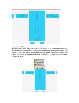
o Reparent Bone (P) Tool
Removing Child Relationship
Reparet Bone
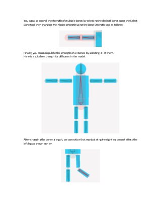
o Manipulating the Bones of the Skeleton
o Bone Strength (S) Tool
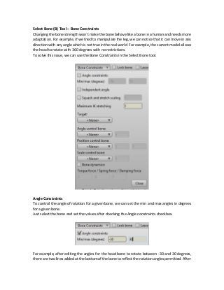
o Select Bone (B) Tool – Bone Constraints
Angle Constraints
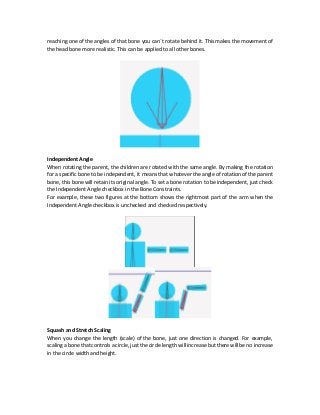
Independent Angle
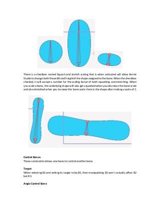
Squash and Stretch Scaling
Control Bones
Target
Angle Control Bone
Position Control Bone
Scale Control Bone
o Switch Layer
o Audio Layer
o Image Layer
Bitmap to Vector
o Group Layer
Selecting Multiple Layers](https://image.slidesharecdn.com/documentation-170921161222/85/Anime-Studio-Pro-10-Tutorial-as-Part-of-Multimedia-Course-5-320.jpg)
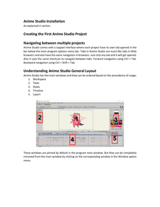
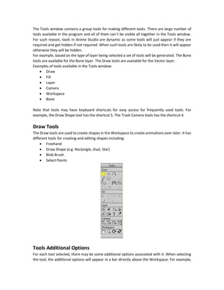
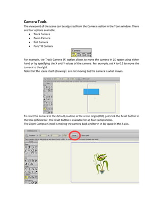
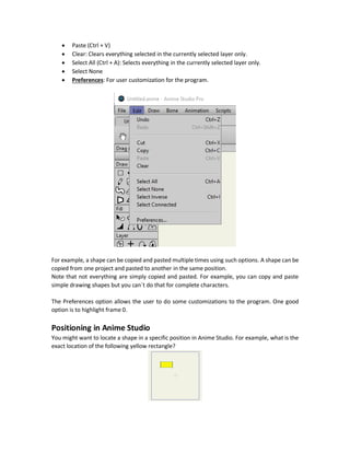
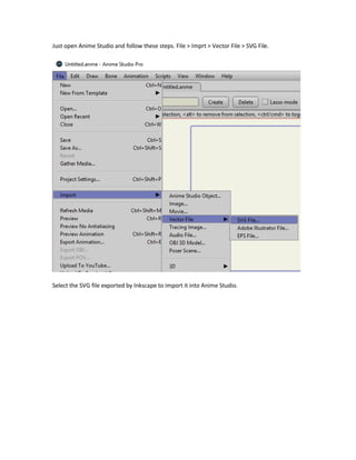
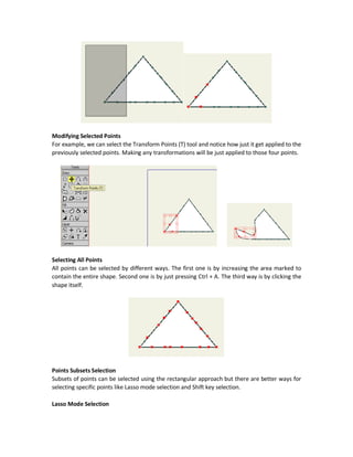
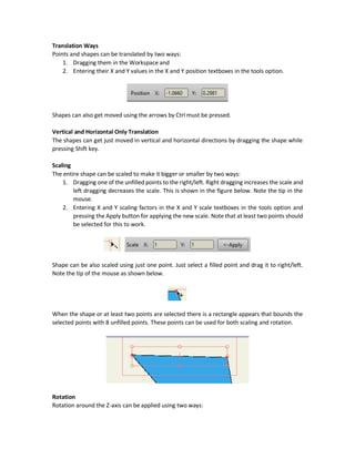
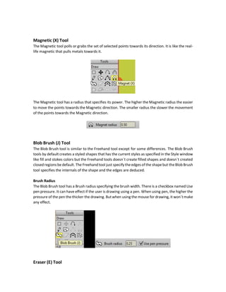
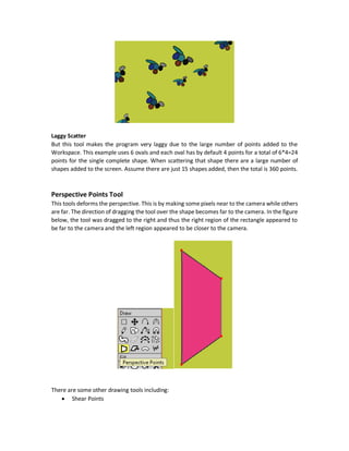
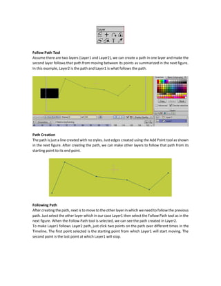
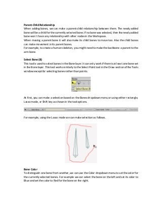
![Note the indentation between the Bone layer (Layer 2)and theVector layer (Layer 1). If two layers
are in the same level that means that there is no parent-child relationship between them.
If you clicked the down triangle of the Bone layer all its layers will be shown and hidden.
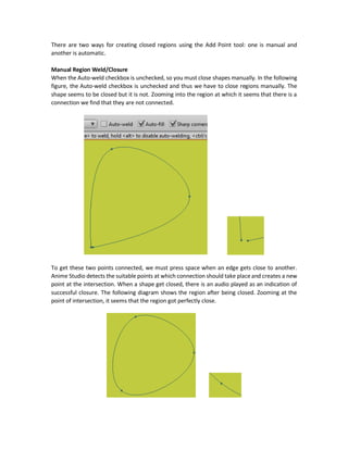
Understanding the Bone Layer Bone Tools
There are a set of tools than can work with the Bone layer only for adding, selecting, and
manipulating bones.
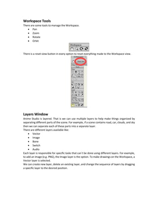
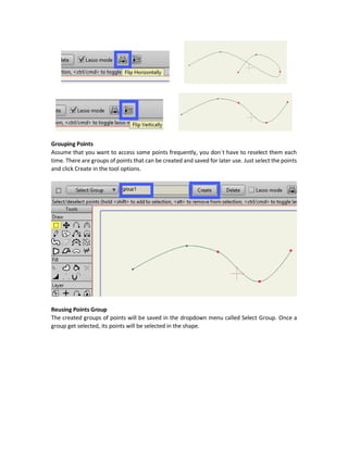
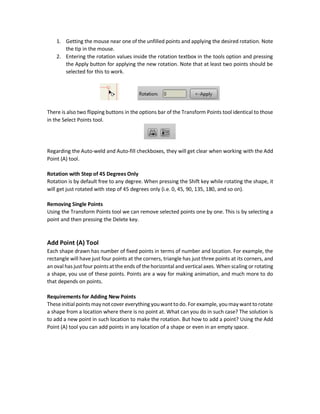
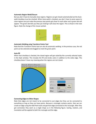
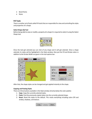
Add Bone (A) [Adding Bones in Bone Layers]
This is the first tool to use when starting creating bones in the Bone layer as it adds new bones.
Just click it and you will find the cursor changed to a new symbol as shown below.
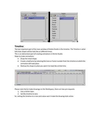
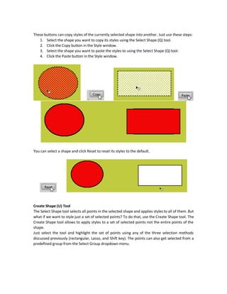
To add a new bone, just click on any empty space in the Workspace and then drag the bone to get
it put into the desired direction and length. When pressing the Shift key the bone will be just
horizontal or vertical. Once a bone get added, it will be assigned a name and get listed as a new
element in the bones dropdown menu. One a bone get selected, it will be colored red by default
and get ready for working with it.
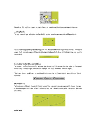
Bone Starting and End Points
You might notice that the bone is wide from the starting point it drawn at and get narrower until
being a point at the point we released the mouse. It is like rotation. The center of rotation is the
starting point. Dragging the end point will rotate the bone around the starting point. The bone
end is the point from which the bone can move freely and the bone start is a fixed point and can`t
move.
After adding at least one bone, all other tools in the Bone section will be activated and get ready
to be used.](https://image.slidesharecdn.com/documentation-170921161222/85/Anime-Studio-Pro-10-Tutorial-as-Part-of-Multimedia-Course-58-320.jpg)

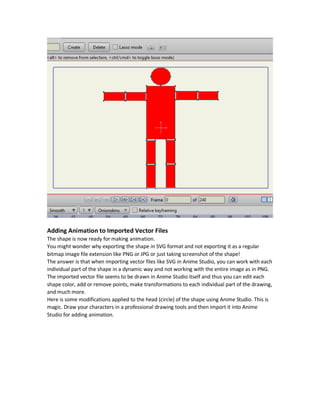
This document is a comprehensive tutorial for an anime studio course, covering various aspects of software installation, project creation, and multifaceted media presentation. It includes detailed sections on tools, layers, timeline management, and the history of anime studio software. The course aims to teach the understanding and application of different media types to create interactive animations effectively.