Download to read offline


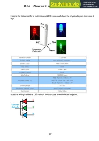
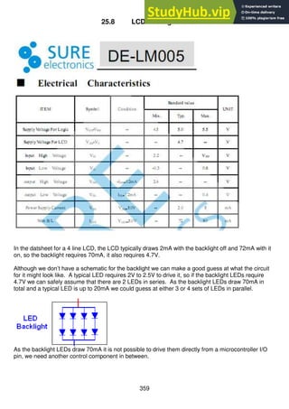


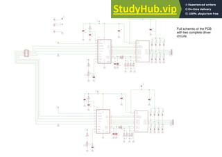


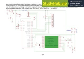
![484
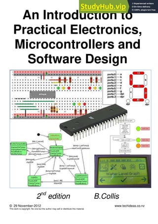
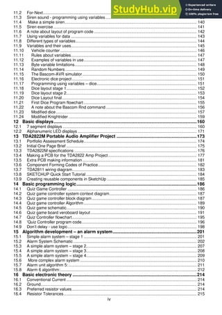
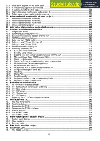
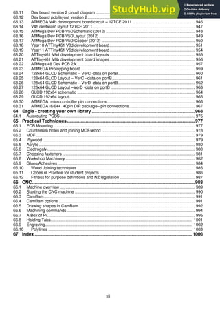
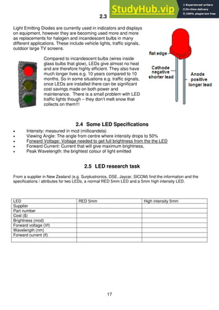
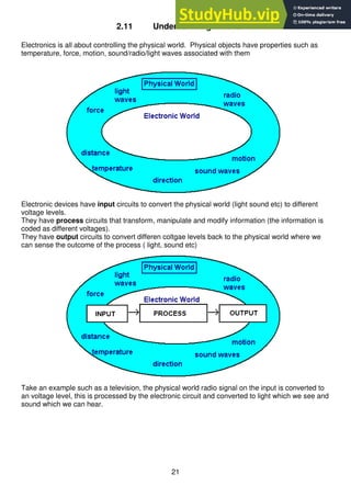
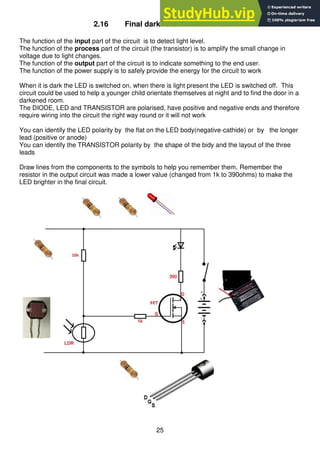
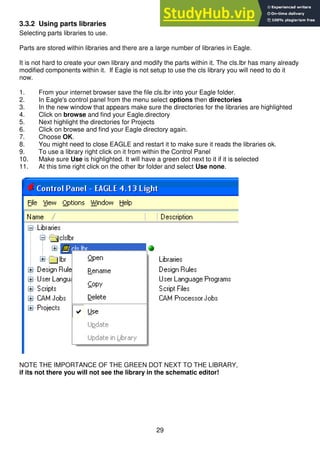
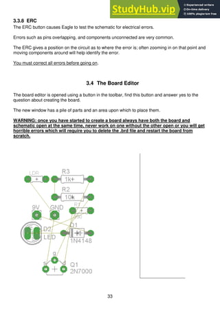
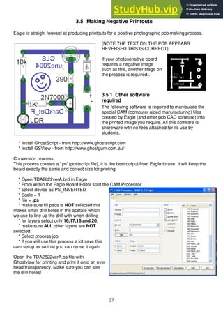
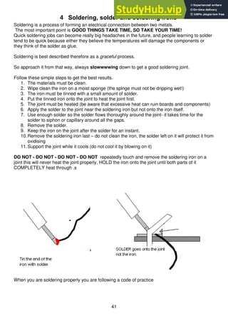
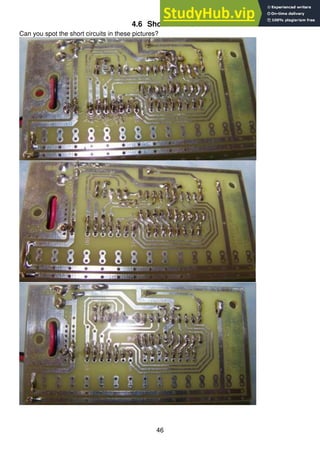
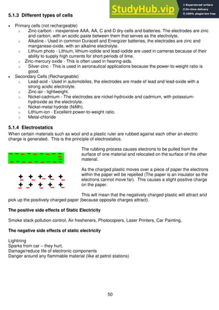
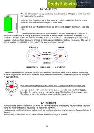
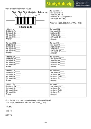
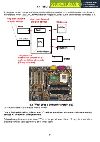
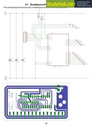
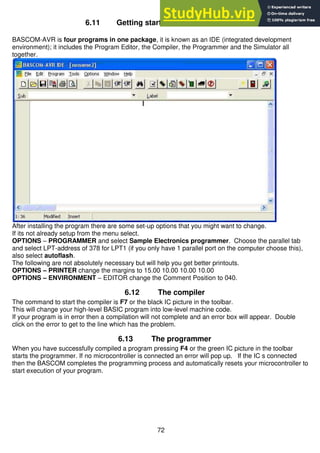
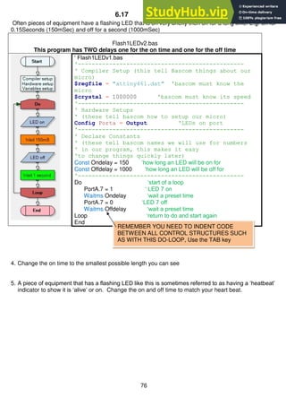
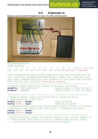
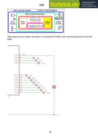
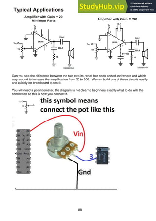
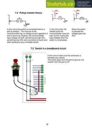
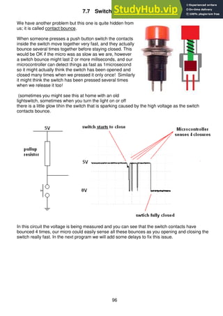
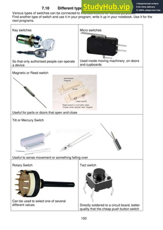
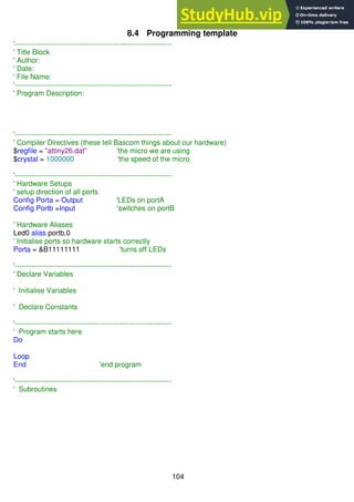
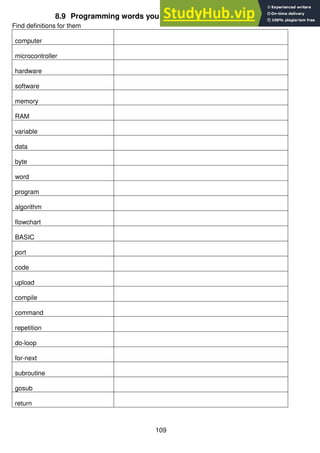
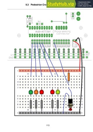
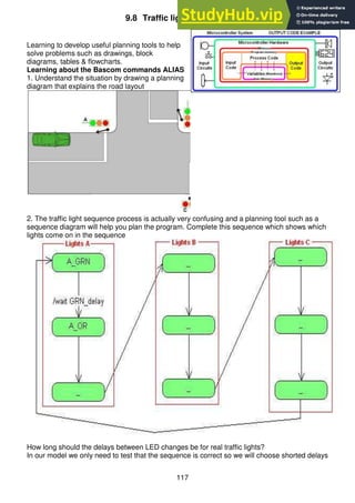
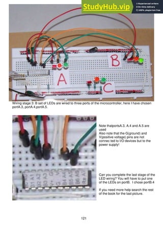
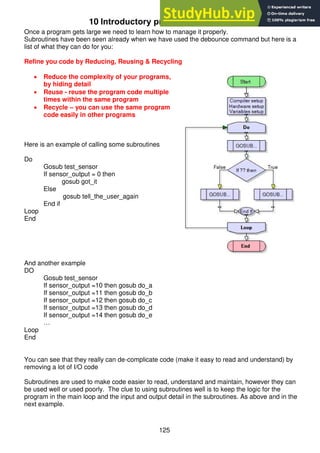
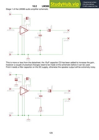
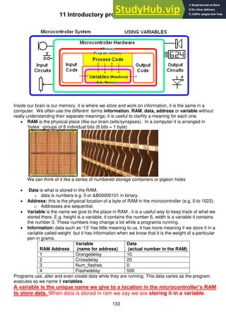
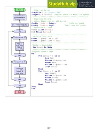
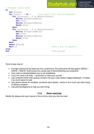
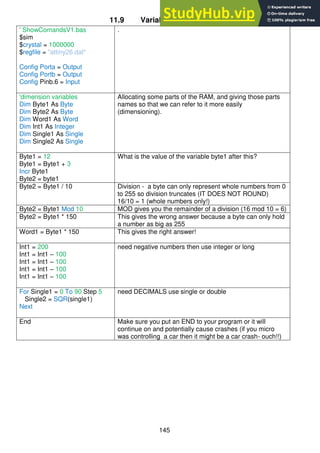
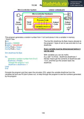
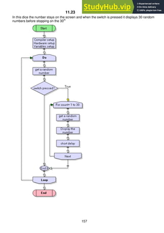
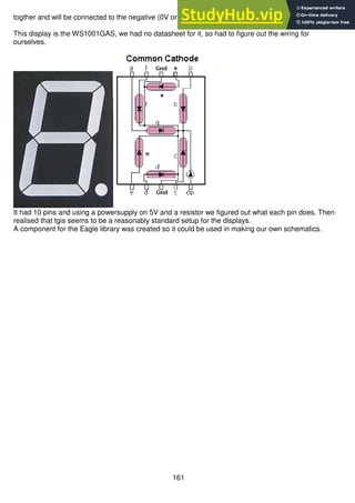
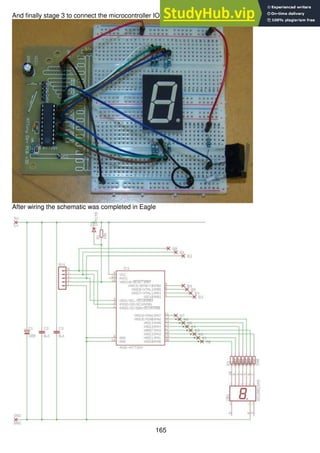
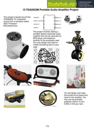
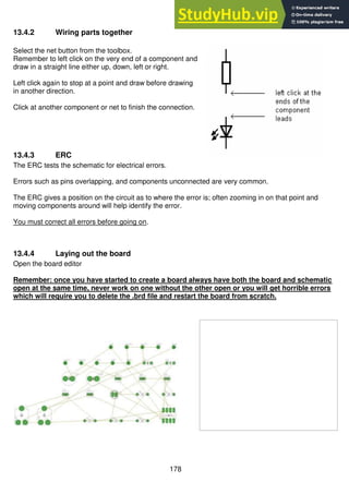
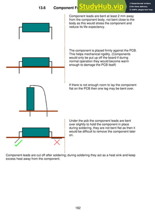
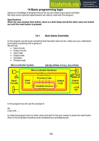
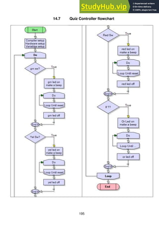
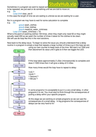
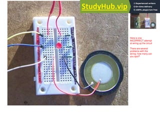
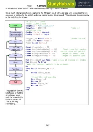
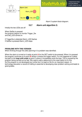
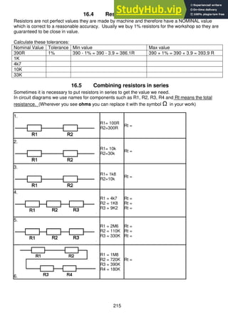
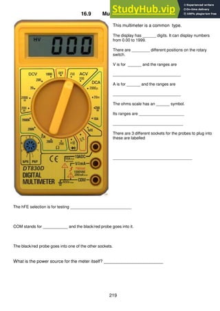
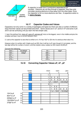
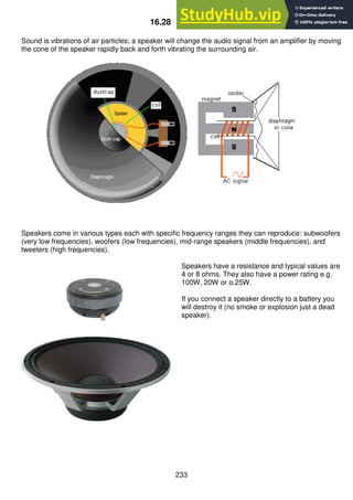
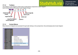
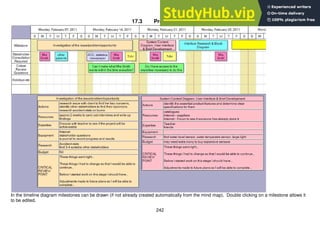
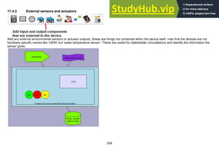
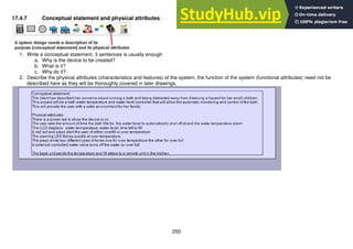
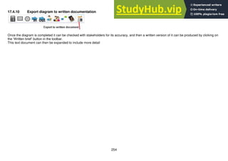
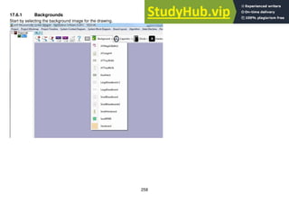
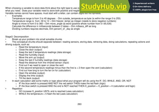
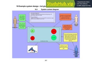
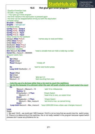
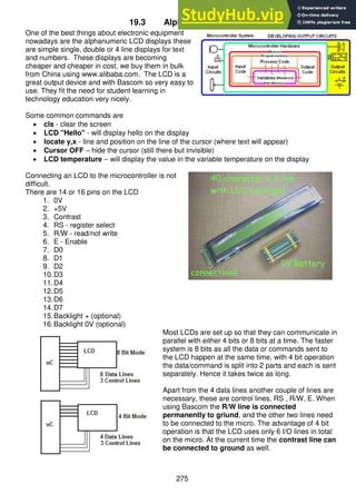
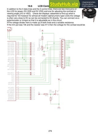
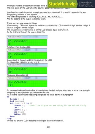
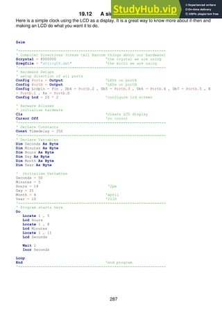
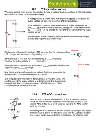
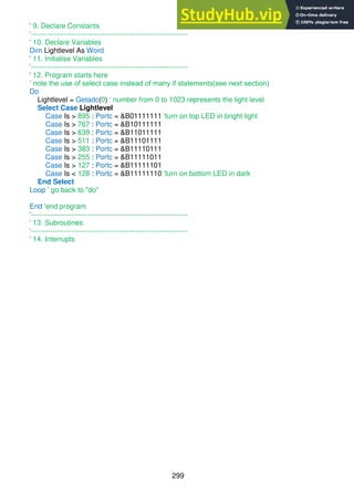
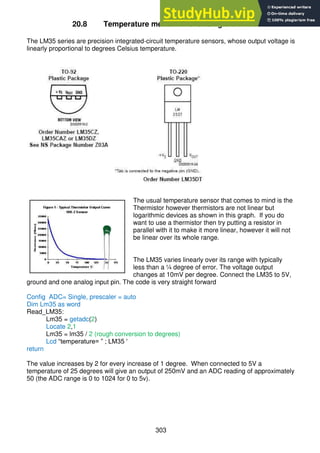
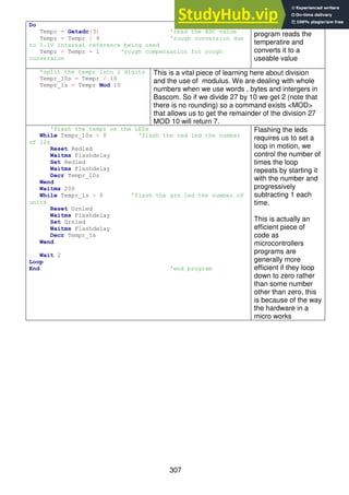
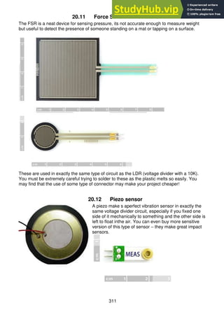
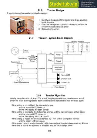
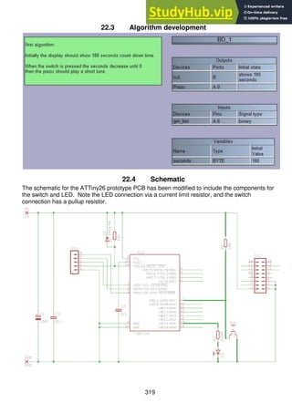
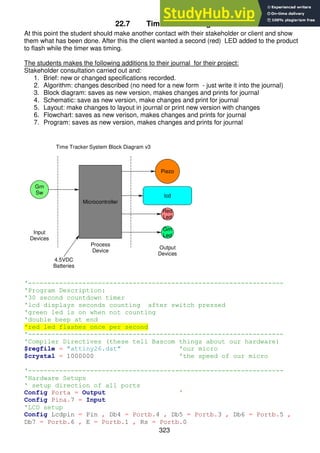
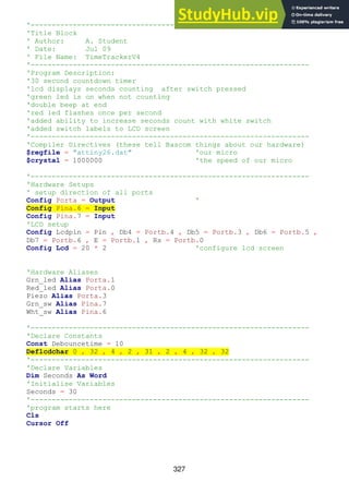
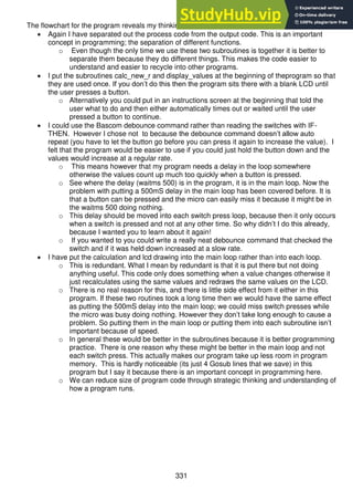
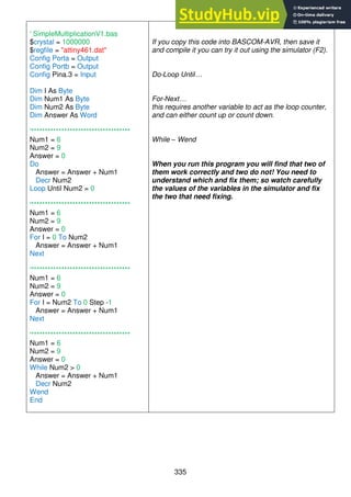
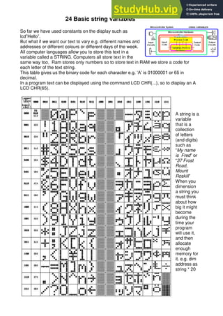
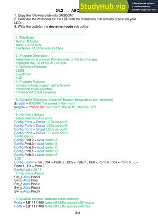
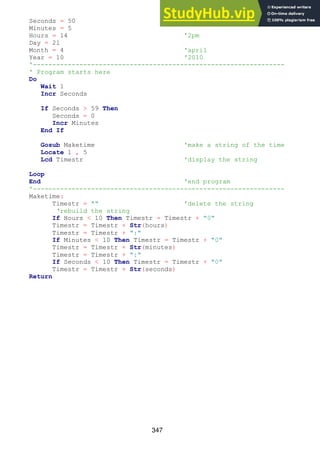
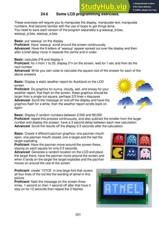
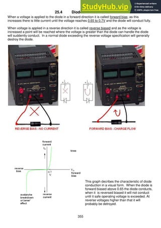
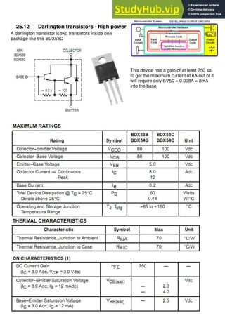
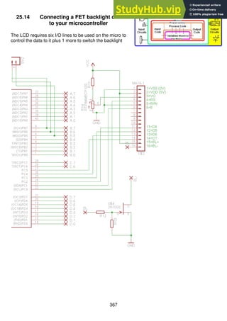
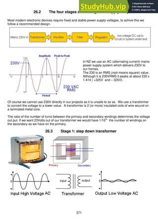
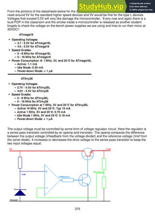
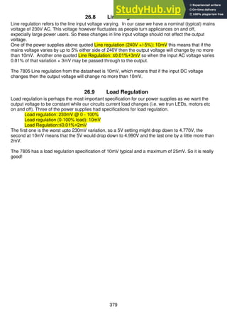
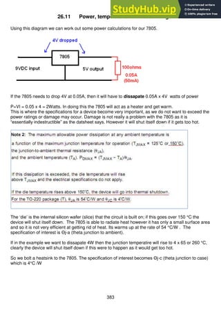
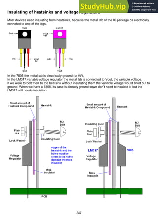
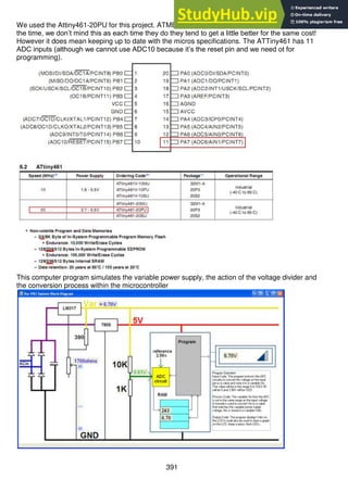
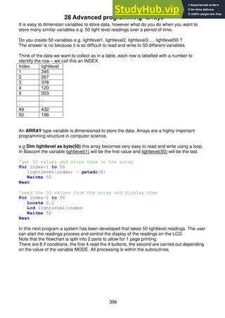
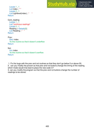
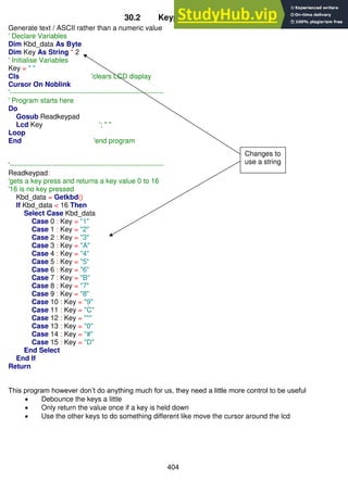
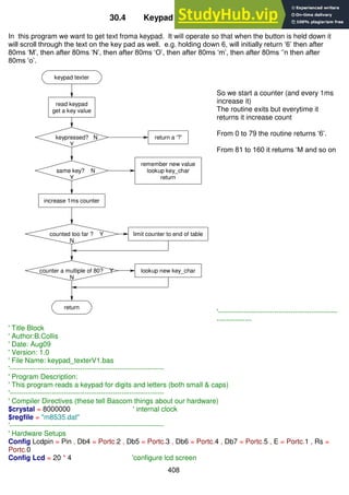
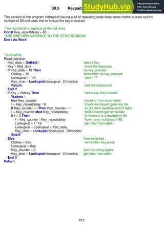
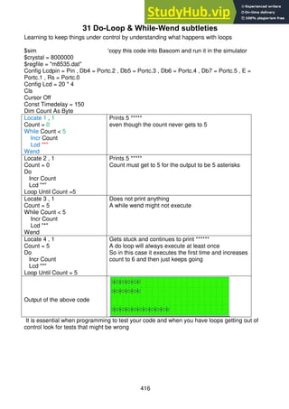
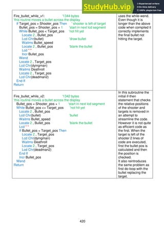
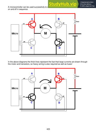
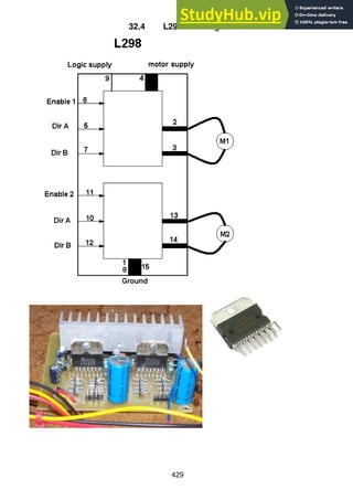
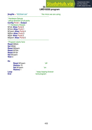
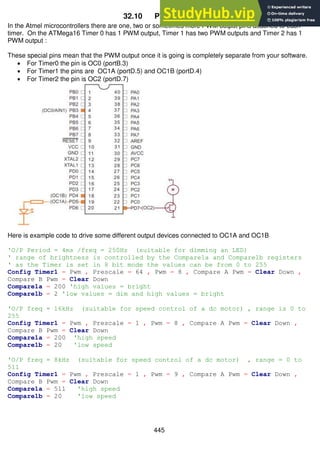
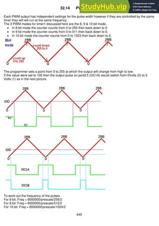
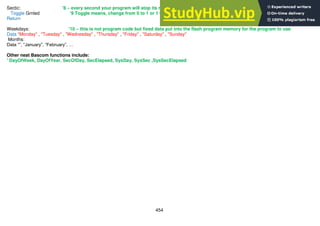
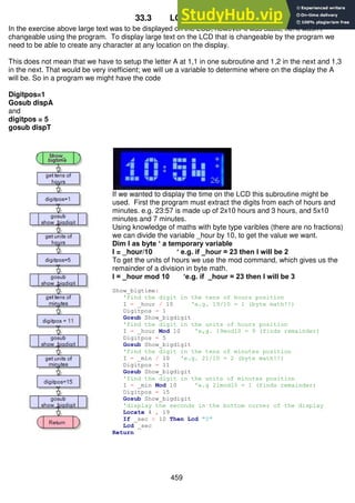
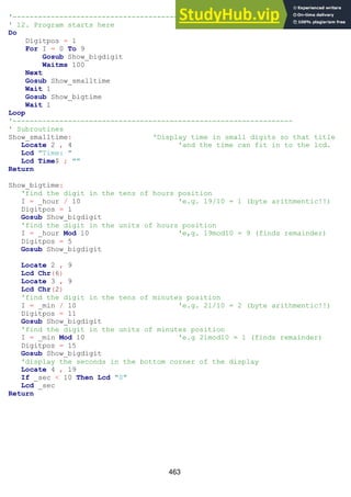
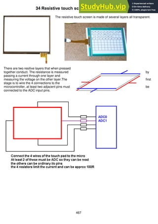
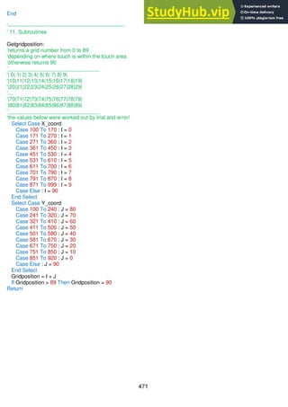
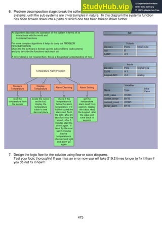
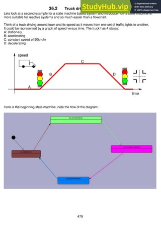
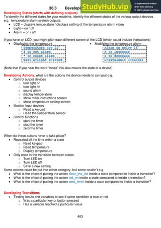
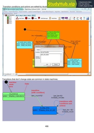
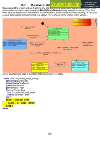
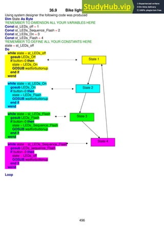
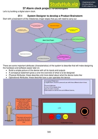
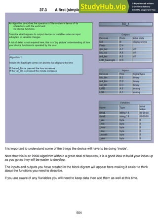
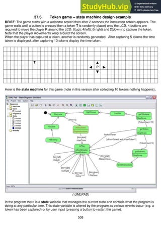
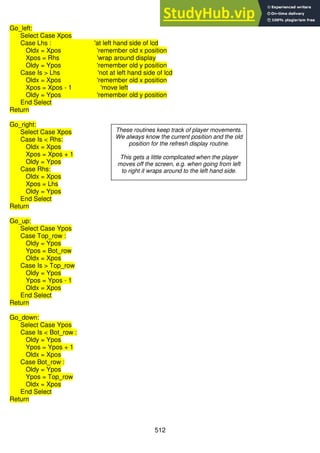
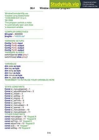
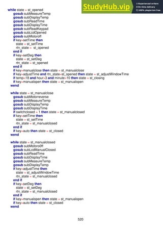
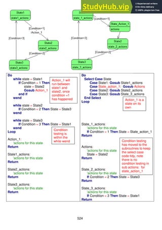
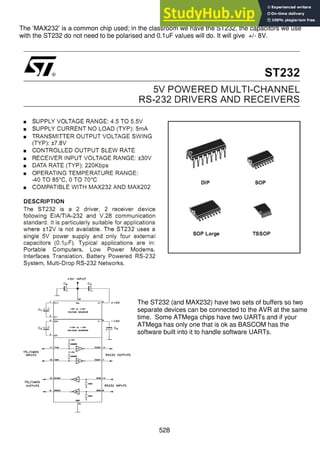
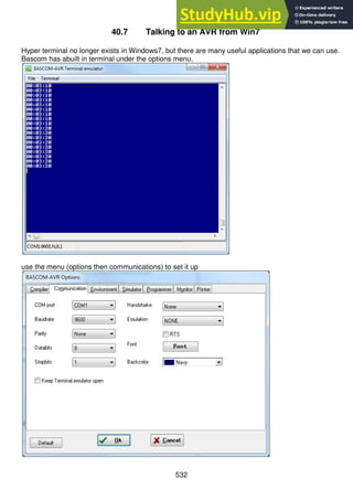
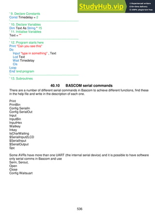
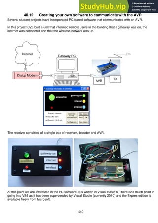
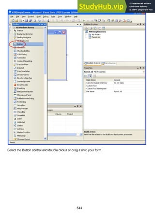
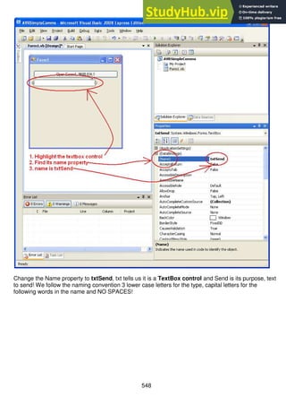
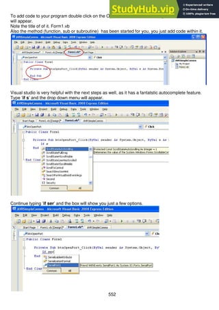
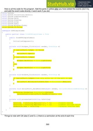
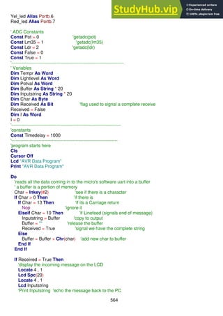
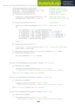
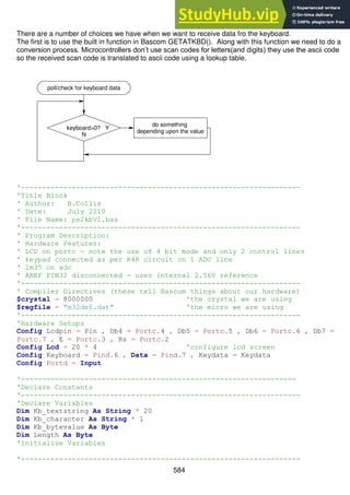
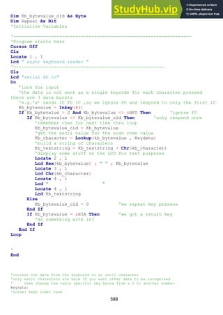
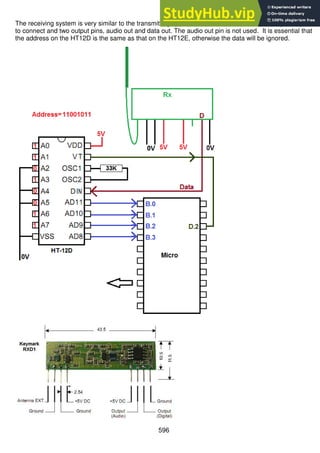
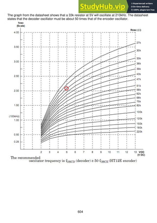
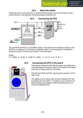
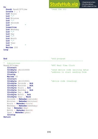
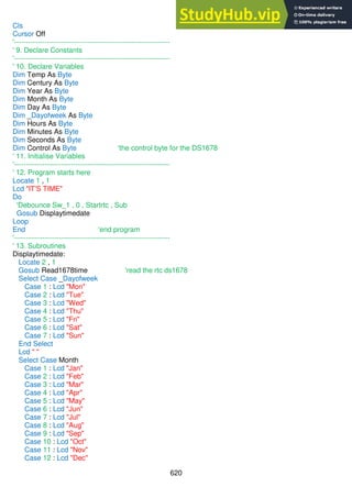
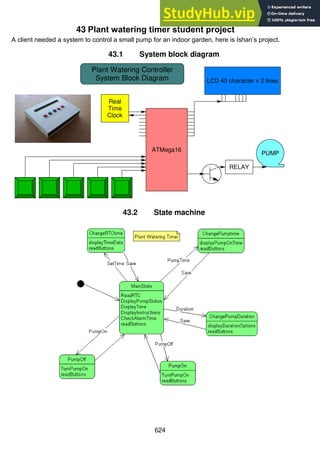
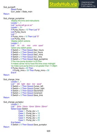
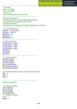
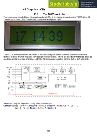
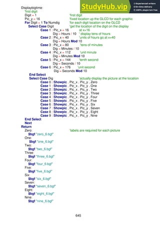
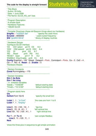
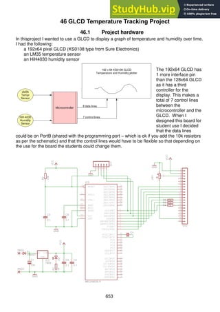
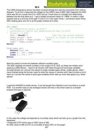
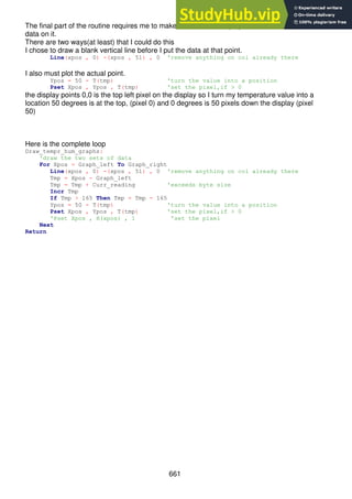
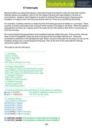
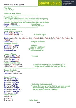
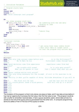
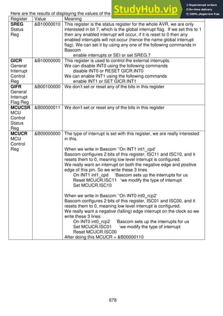
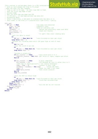
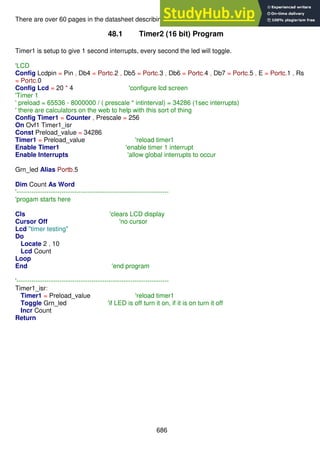
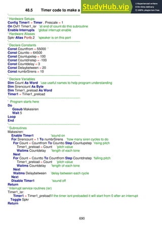
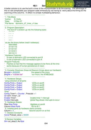
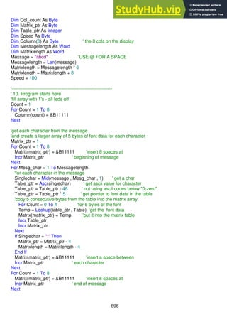
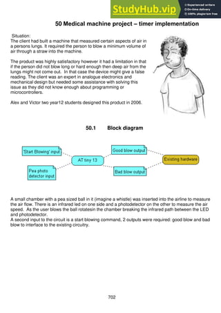
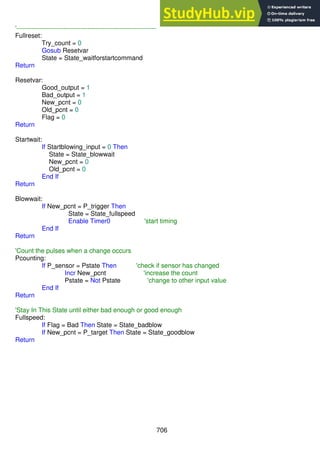
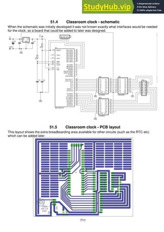
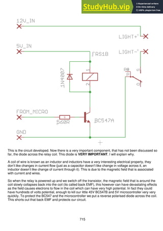
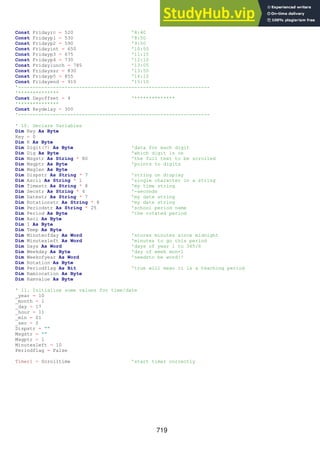
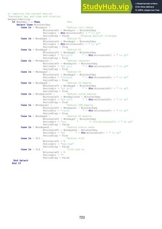
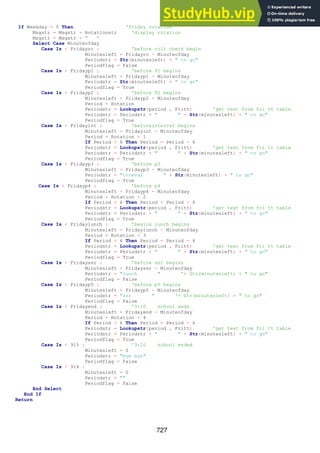
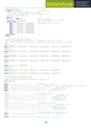
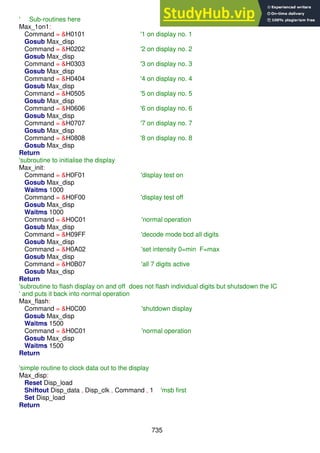
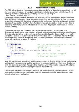
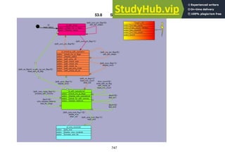
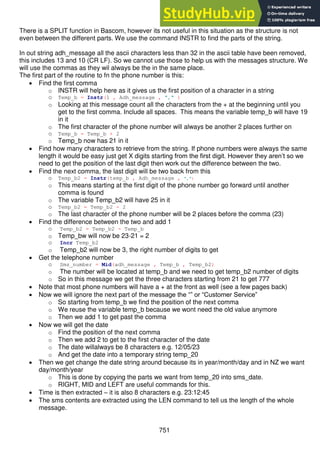
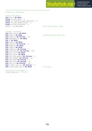
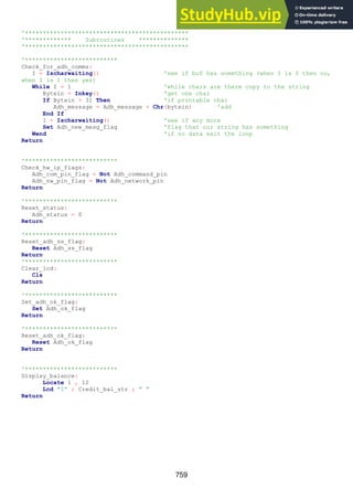
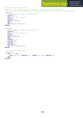
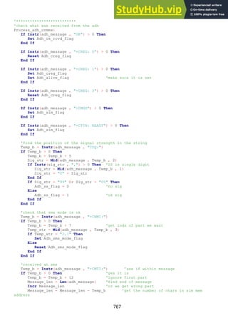
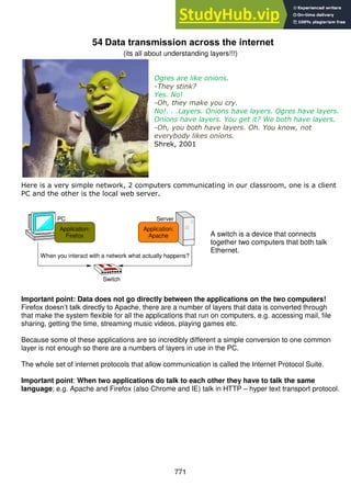
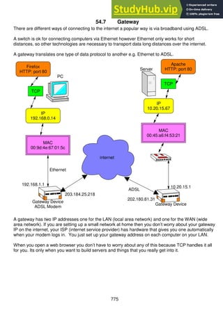
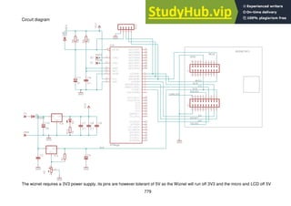
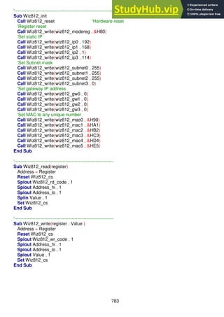
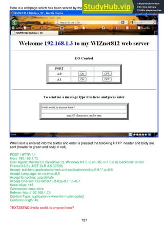
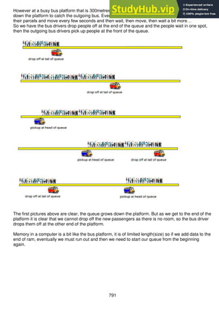
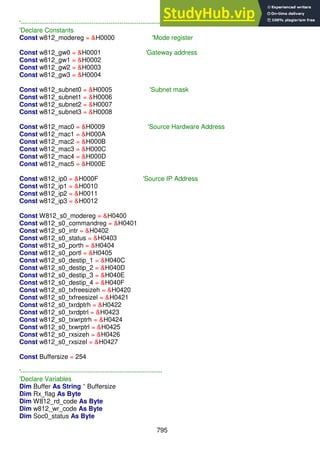
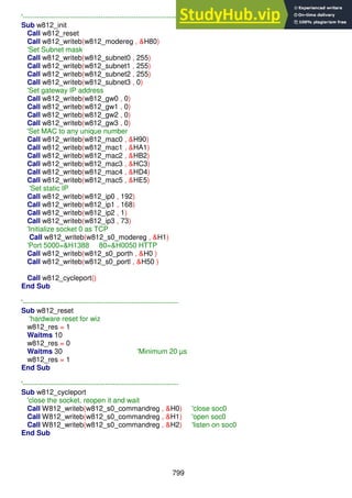
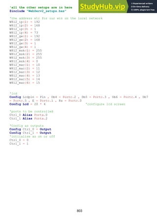
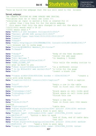
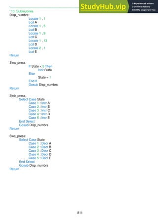
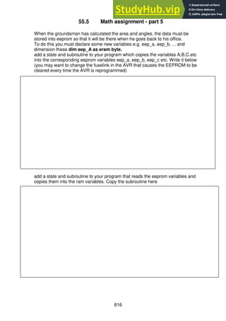
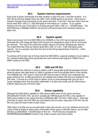
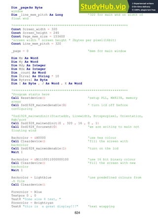
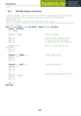
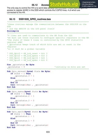
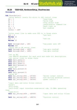
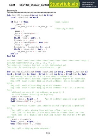
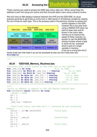
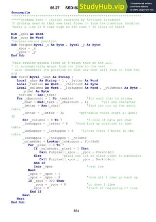
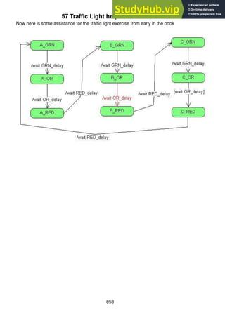
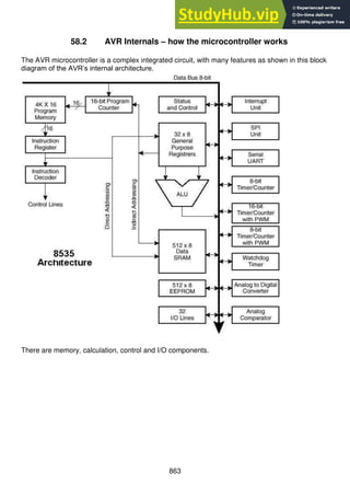
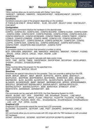
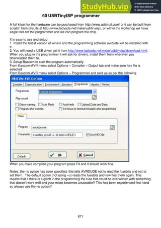
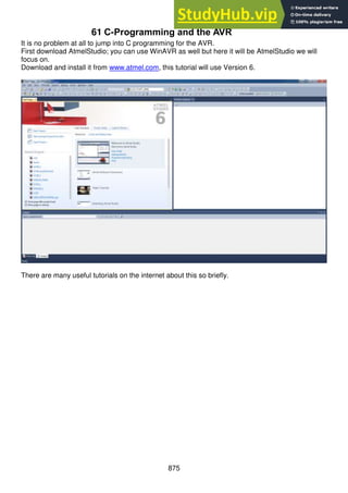
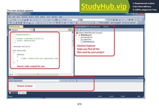
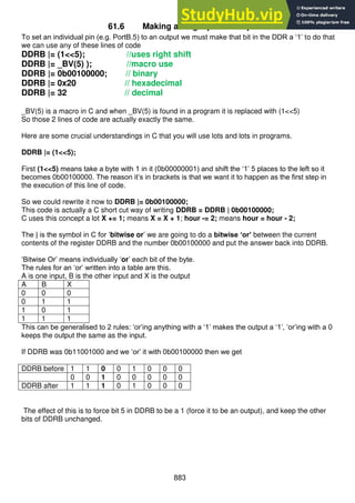
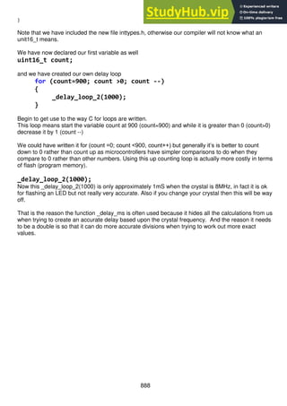
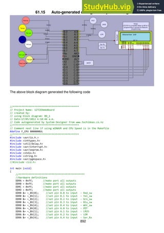
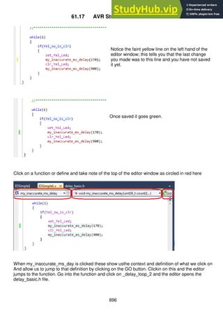
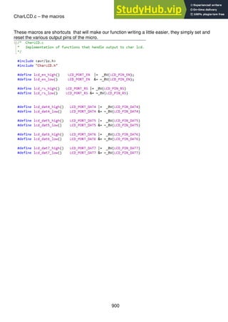
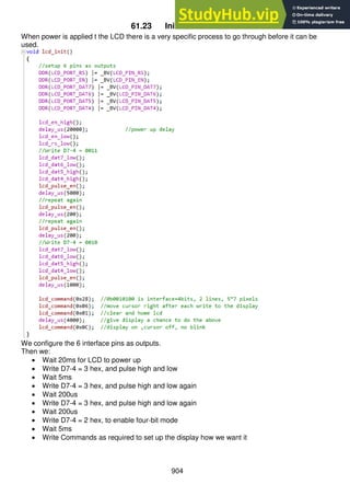
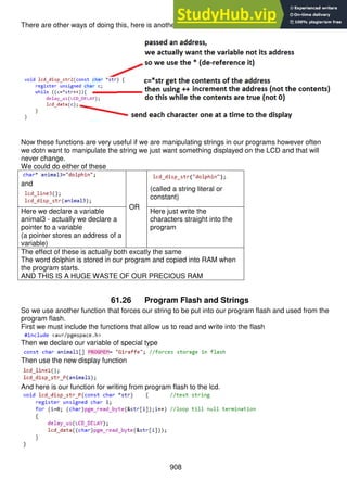
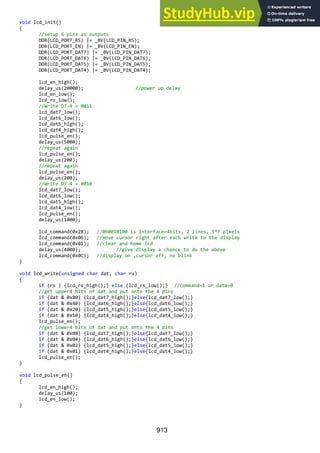
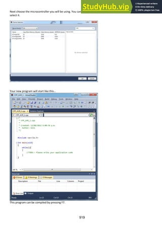
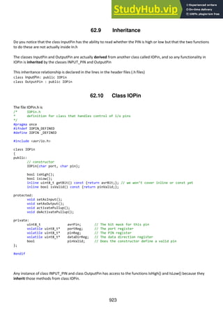
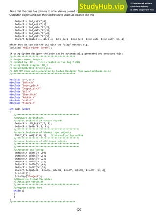
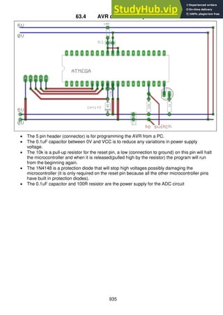
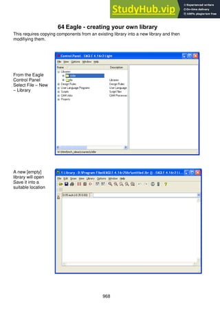
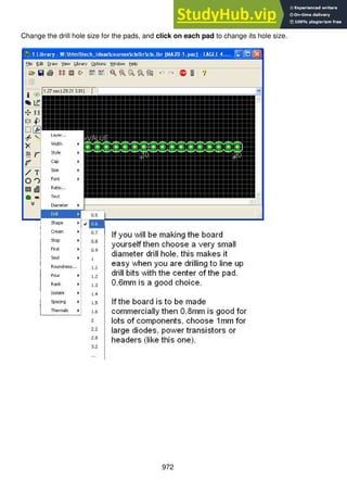
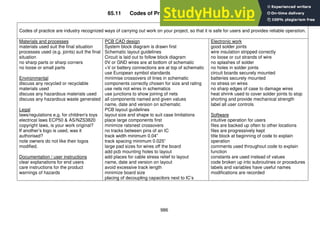
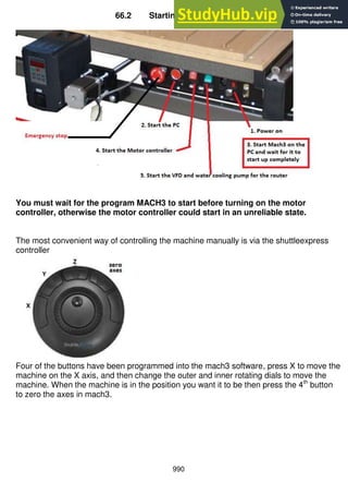
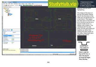
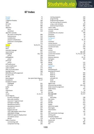
36.4 A state machine for the temperature alarm system
Here are the 4 states for the temperature controller and a diagram representation of it
State 1: measure and display
temperature
State 2: light and alarm are both on
State 3: light only is on
State 4: modify the preset temp alarm
setting
Each state includes the names of ations(subroutines) that will be called to do different things. It is good
practice not to put code into the state, so that the control structure is not confused with control of I/O
devices. Also if any subroutine is complex it may require a flowchart or even another state machine to
plan it.
The second part of the process is to build the transitions between the states and what conditions cause
them to occur. The
black circle indicates the
starting state for when
power is applied.
Here one transition is
shown for when the
temperature reading has
fallen below the set
level.
A condition is in square
brackets [ ], it looks like
any test that would be
part of an if…then,
while… wend or do loop
until…
Along with the condition
are the actions you want
the program to carry out
after one state has
stopped execution and
before the next state
starts executing. An
action could be a call to
a subroutine or a very
short one or two lines of
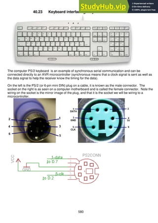
code. Actions are
optional, but almost all
(though not all) transitions will have conditions](https://image.slidesharecdn.com/anintroductiontopracticalelectronicsmicrocontrollersandsoftwaredesign-230807154315-4eeee865/85/An-Introduction-to-Practical-Electronics-Microcontrollers-and-Software-Design-pdf-484-320.jpg)


![827
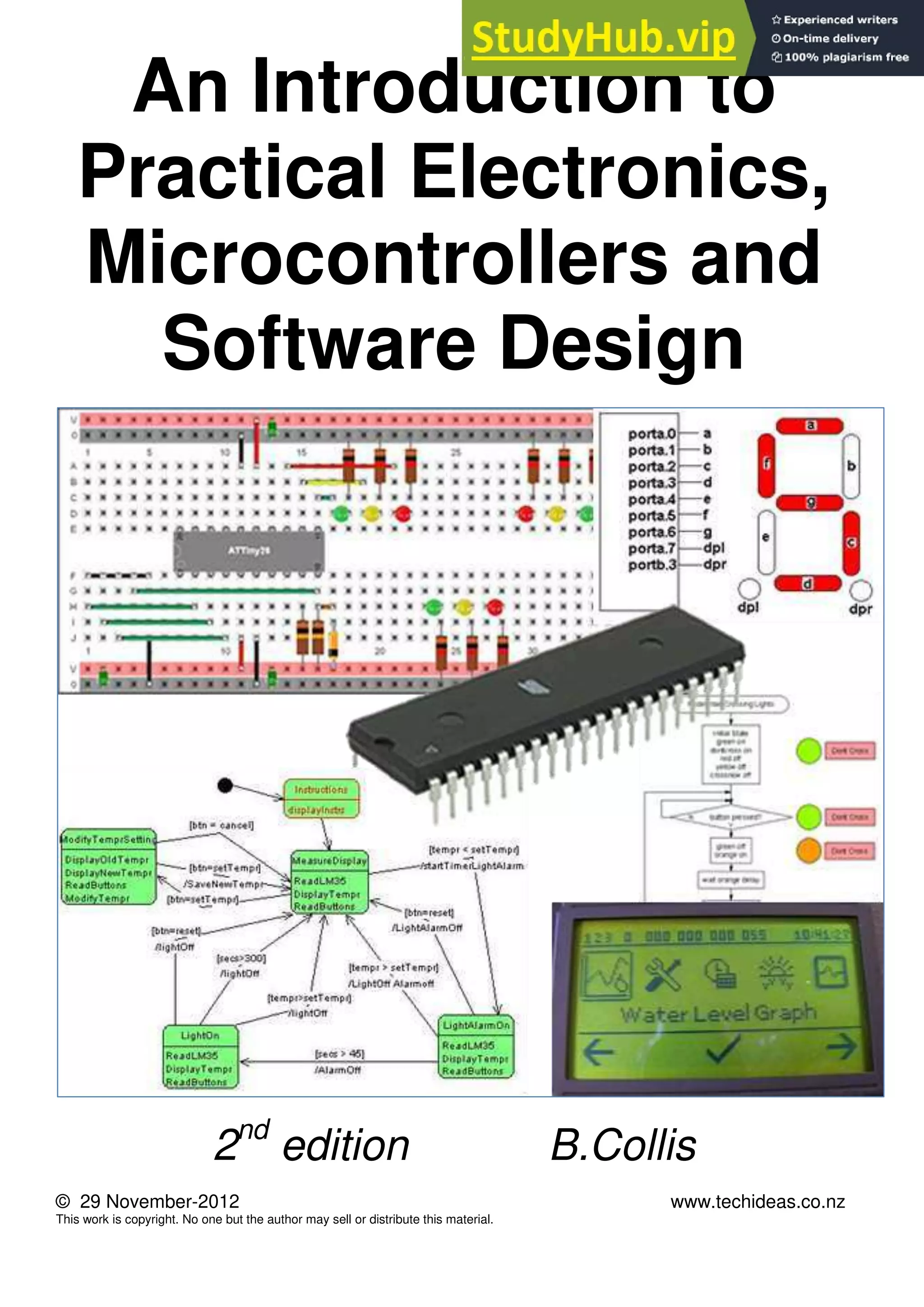
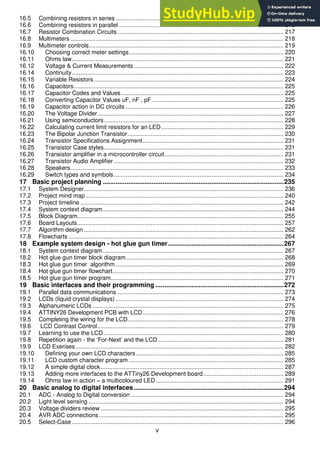
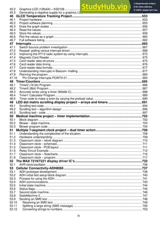
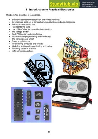
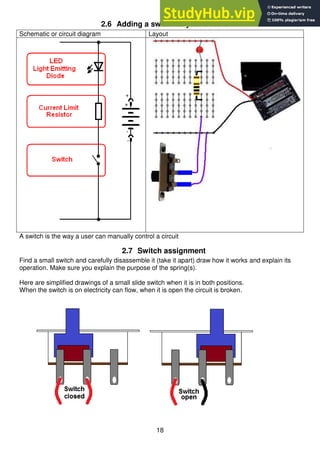
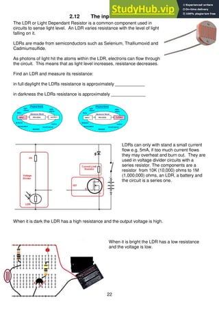
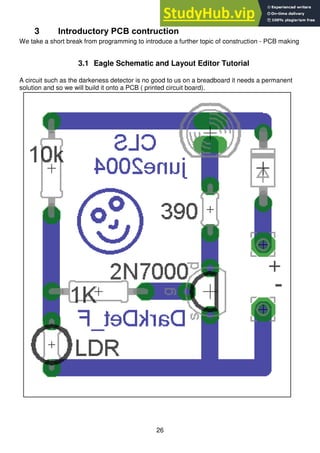
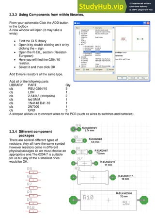
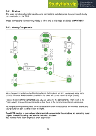
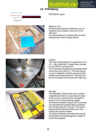
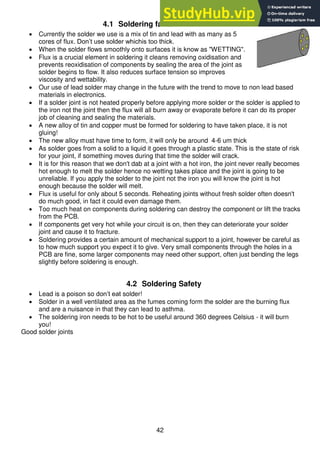
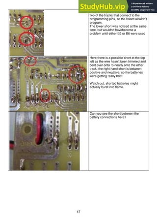
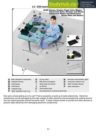
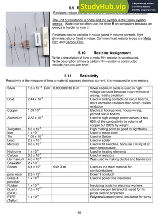
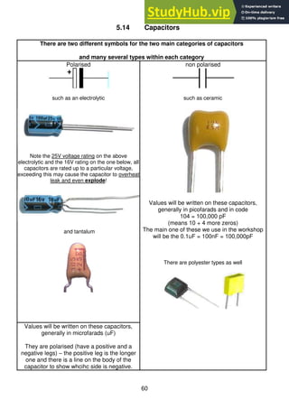
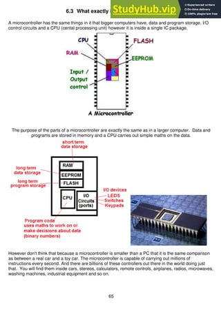
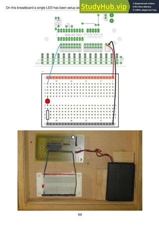
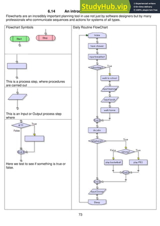
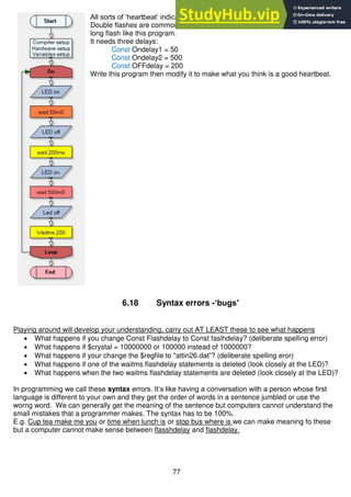
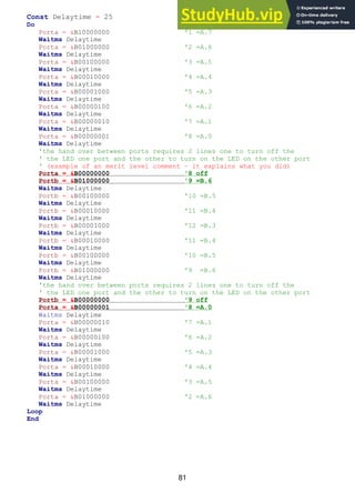
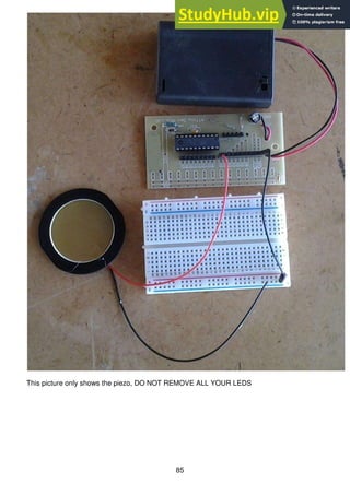
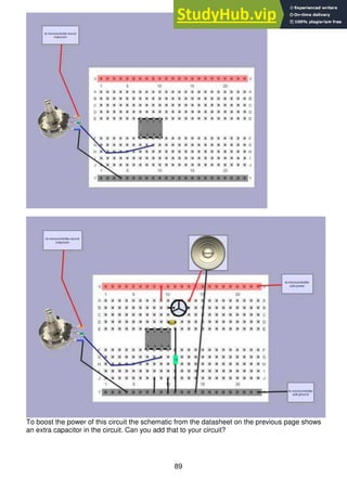
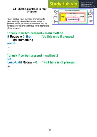
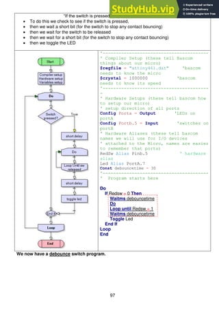
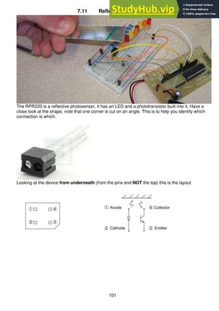
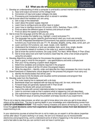
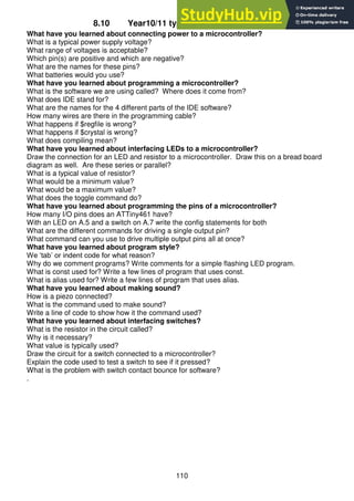
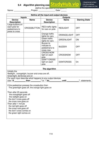
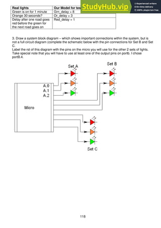
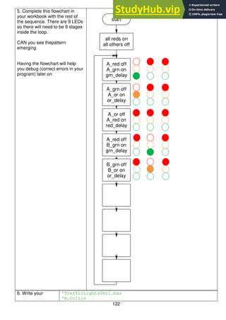
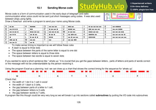
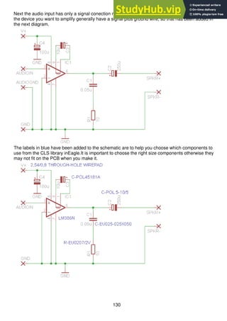
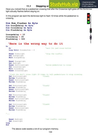
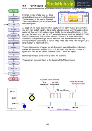
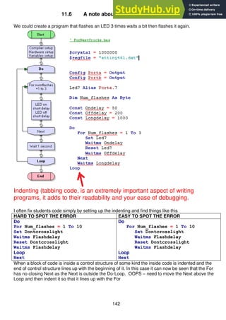
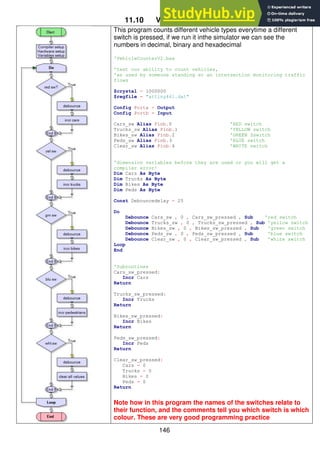
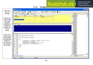
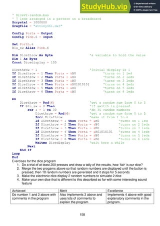
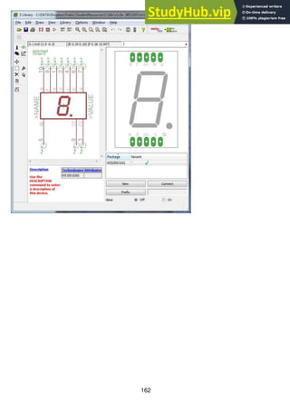
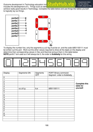
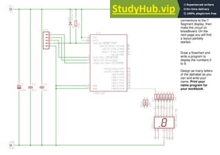
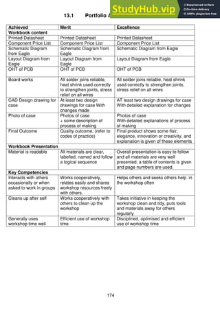
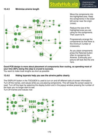
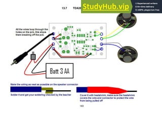
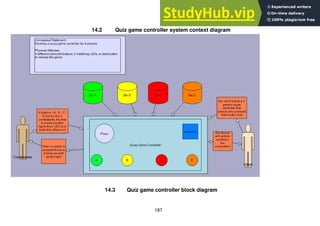
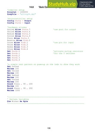
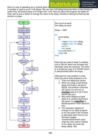
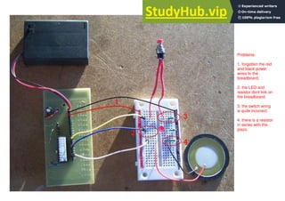
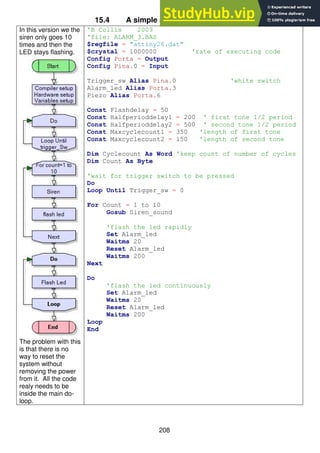
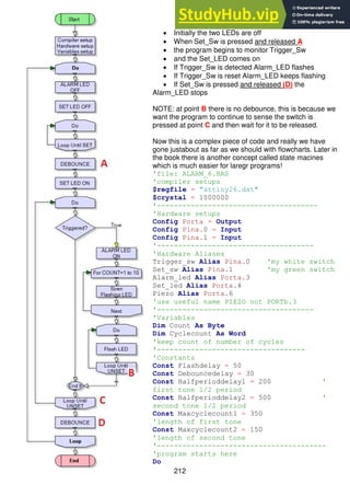
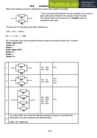
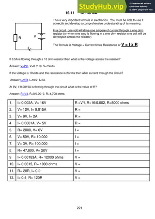
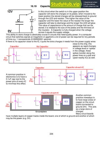
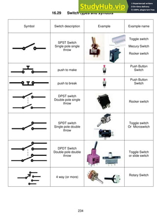
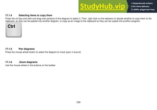
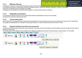
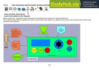
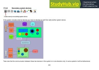
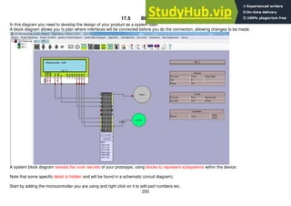
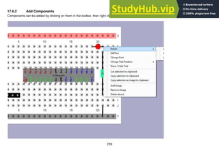
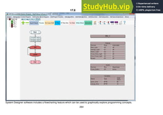
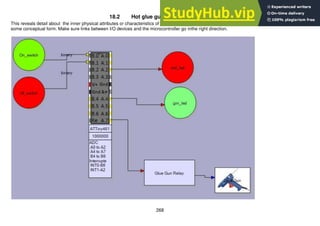
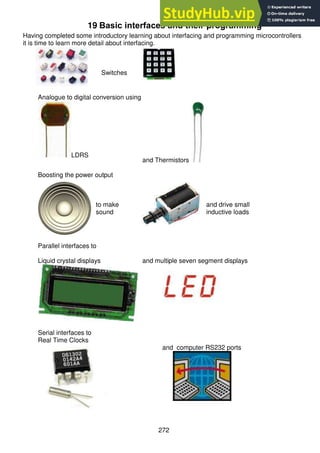
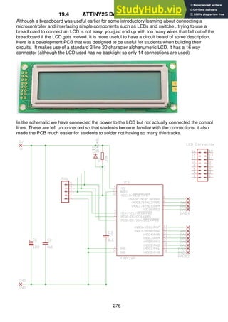
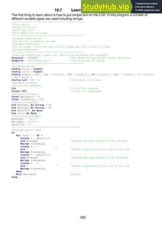
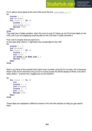
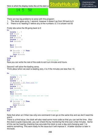
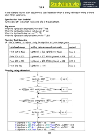
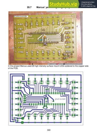
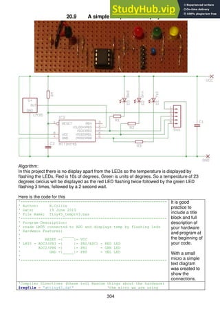
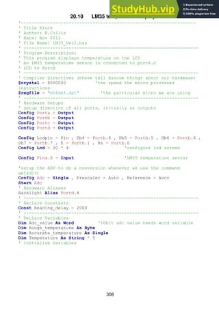
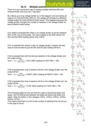
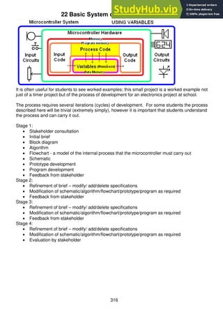
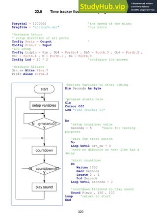
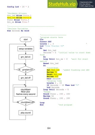
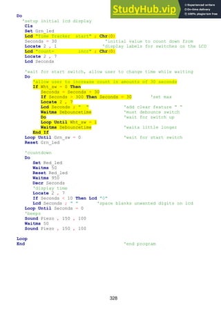
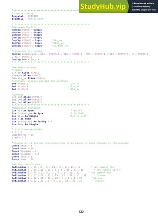
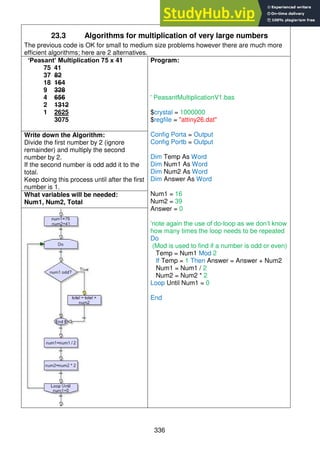
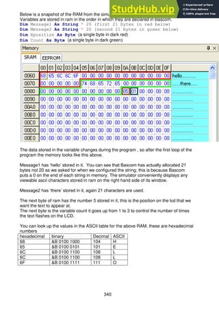
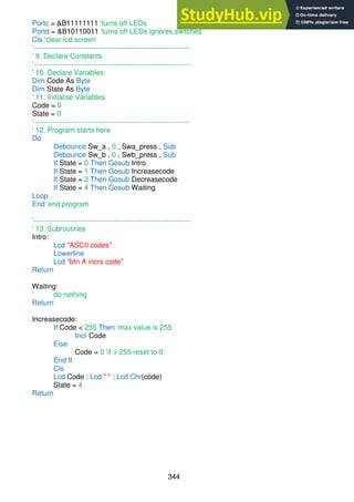
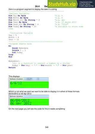
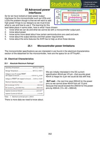
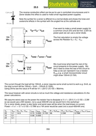
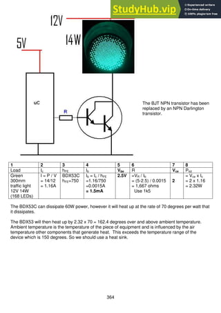
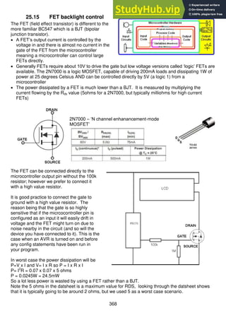
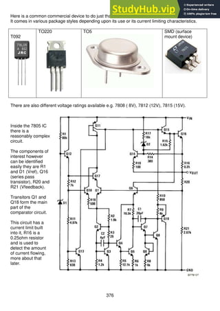
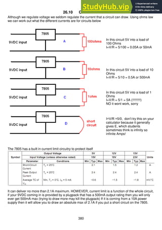
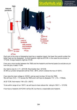
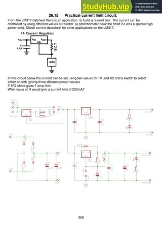
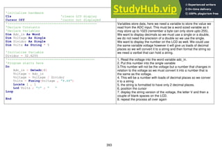
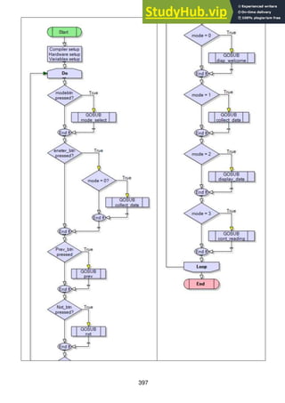
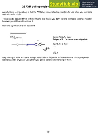
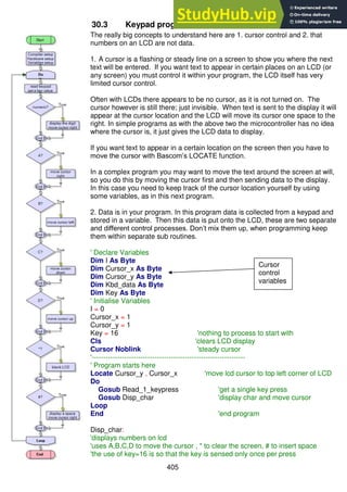
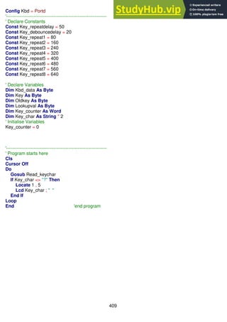
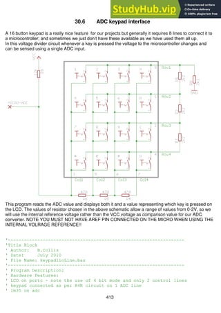
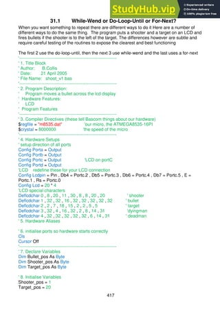
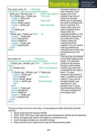
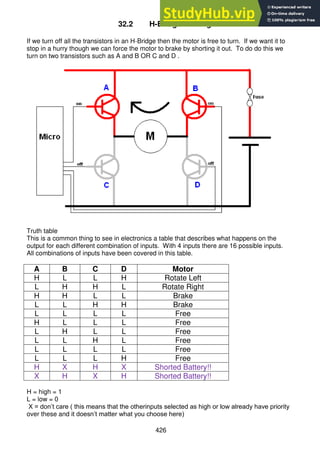
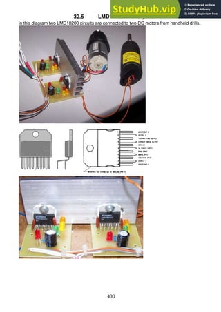
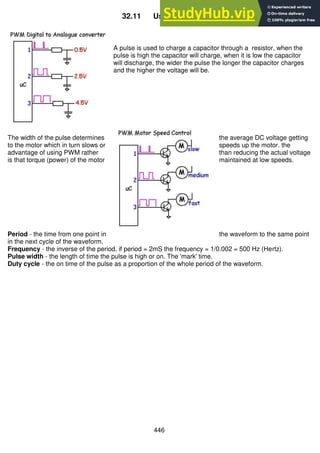
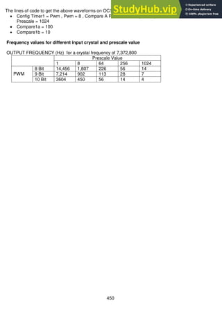
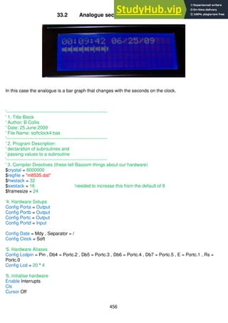
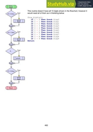
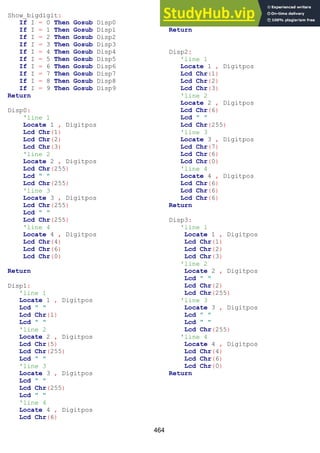
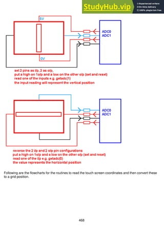
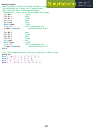
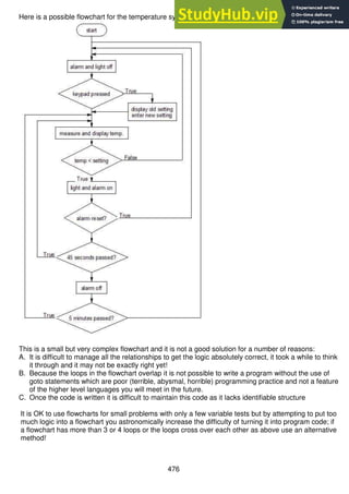
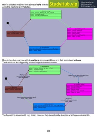
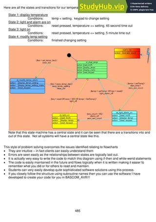
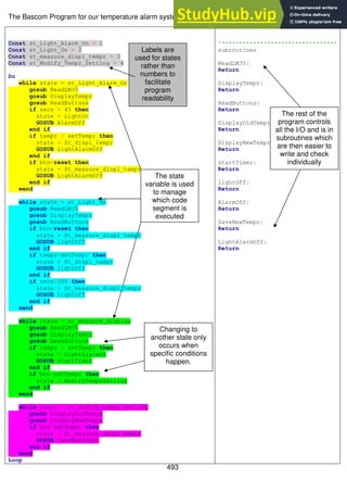
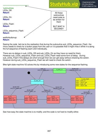
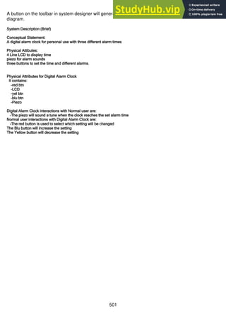
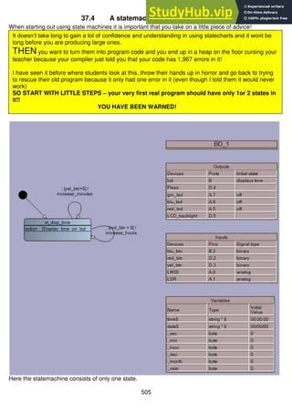
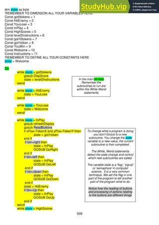
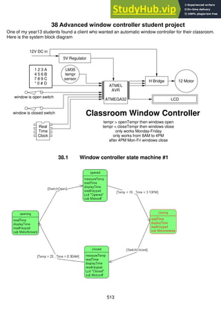
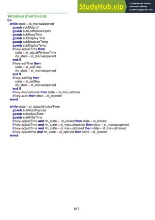
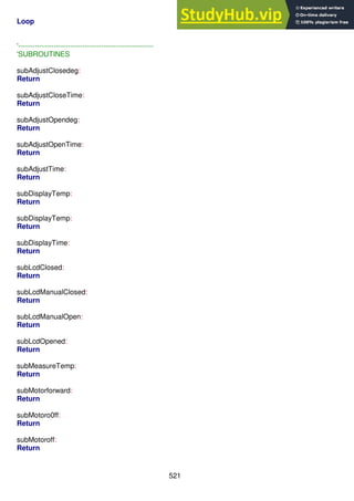
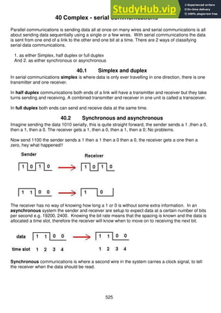
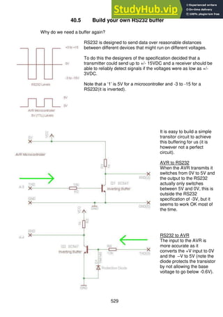
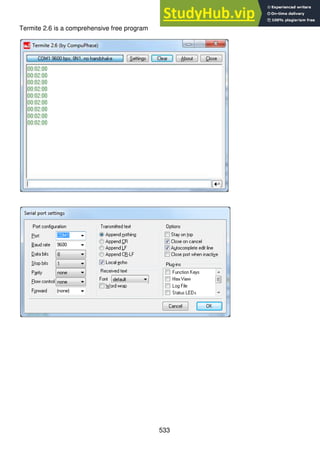
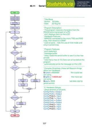
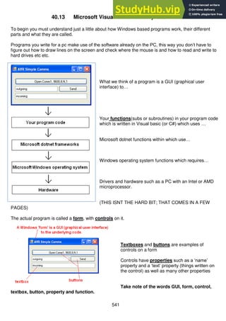
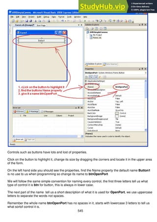
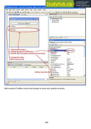
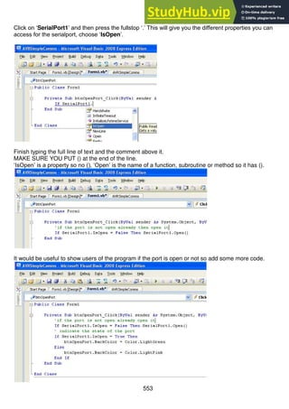
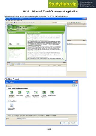
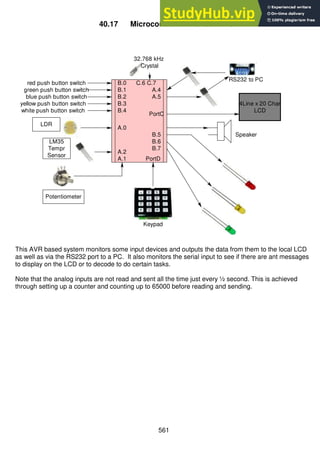
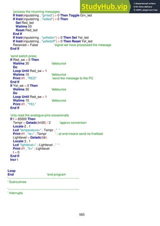
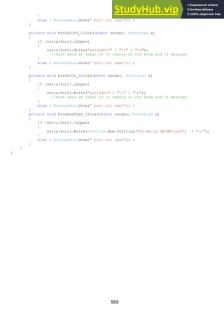
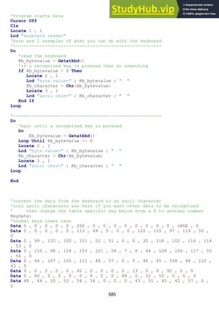
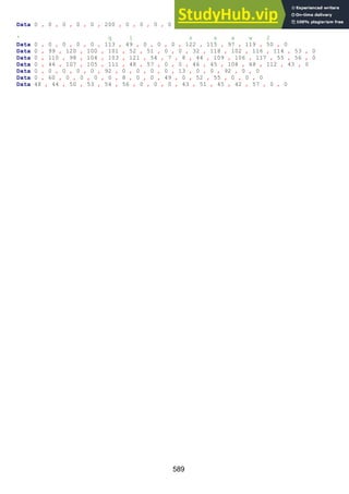
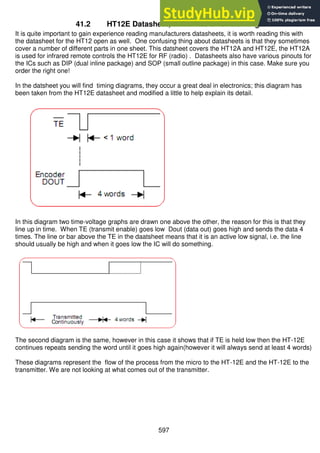
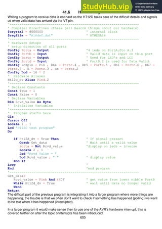
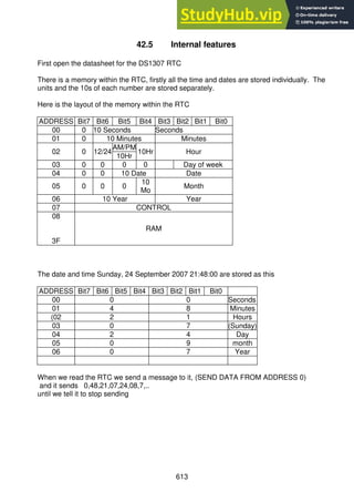
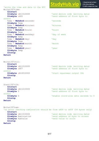
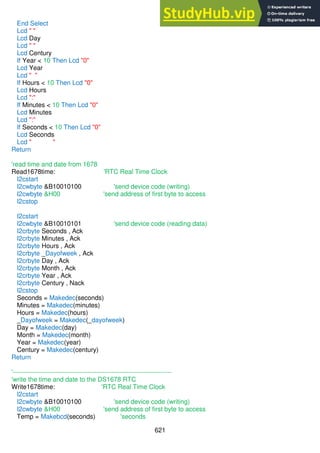
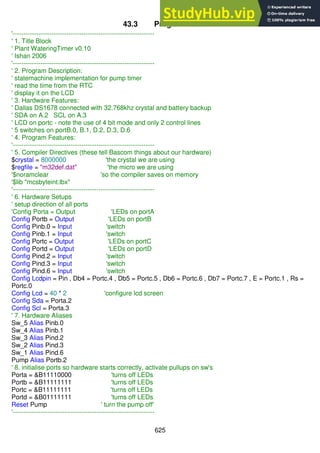
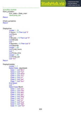
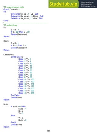
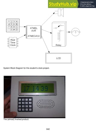
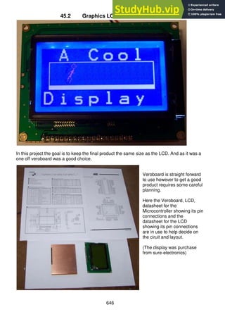
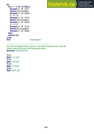
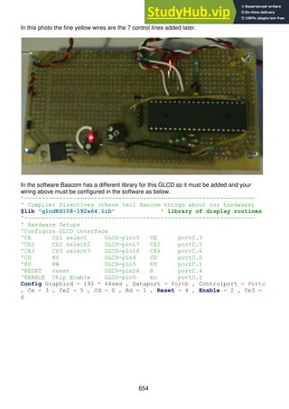
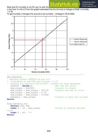
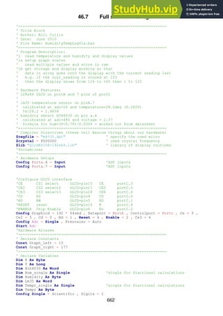
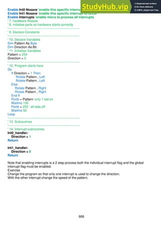
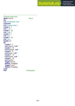
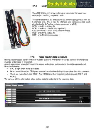
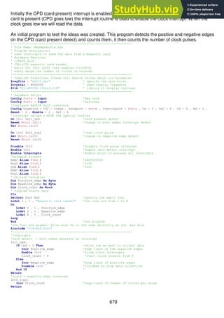
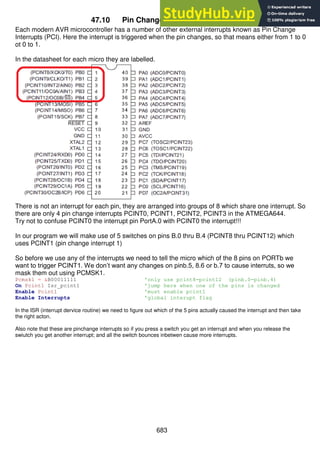
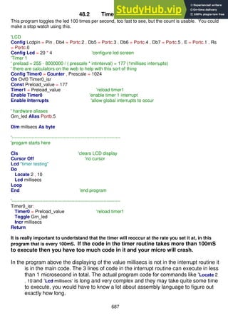
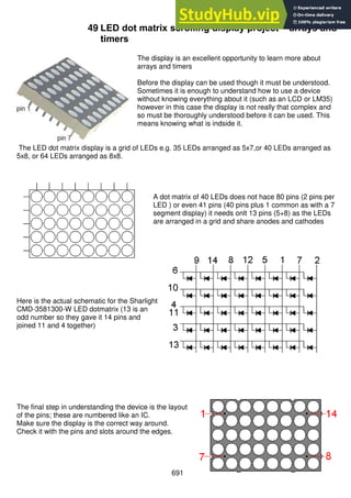
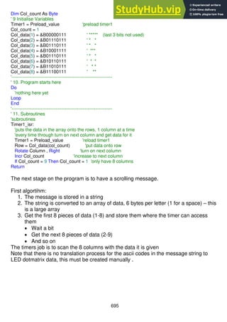
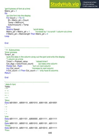
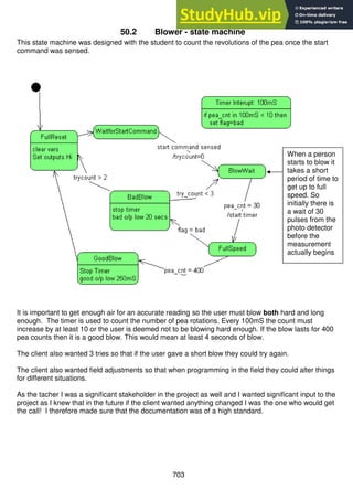
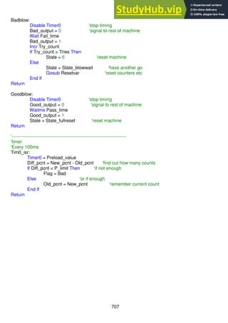
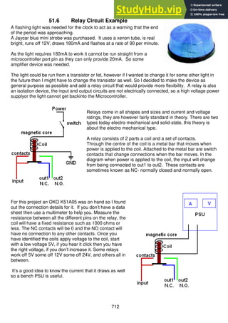
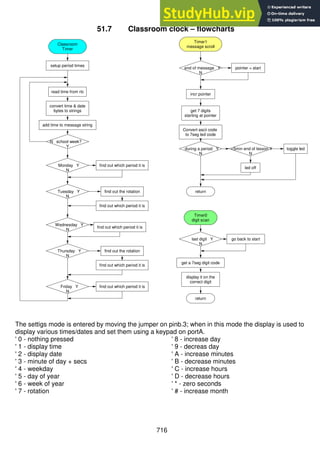
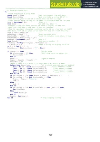
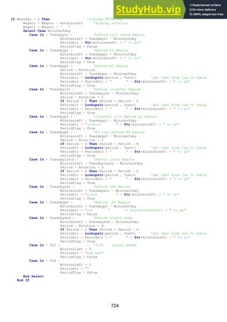
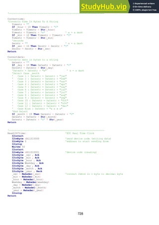
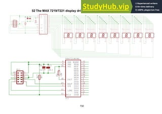
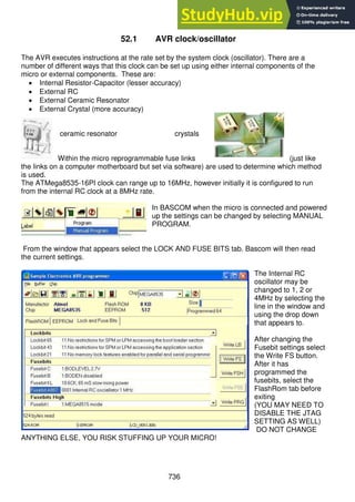
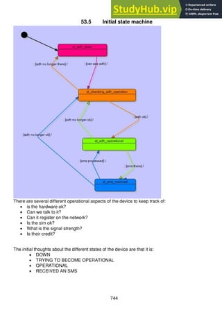
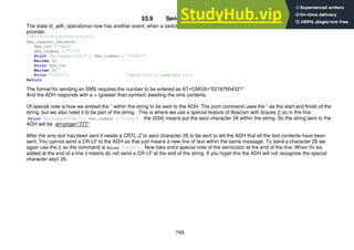
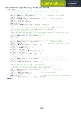
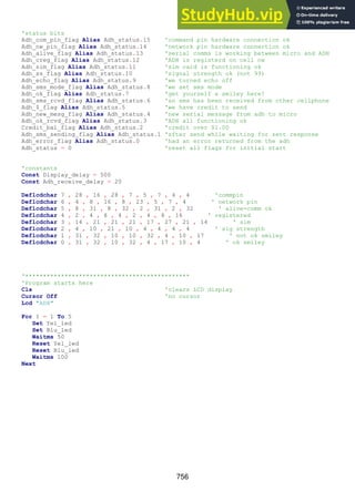
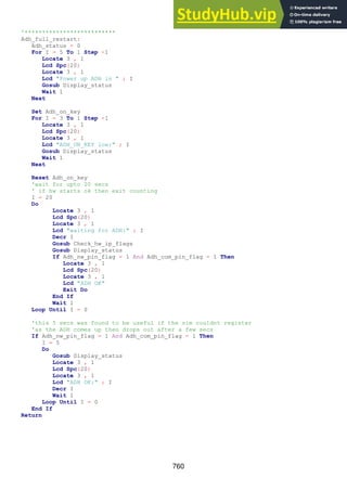
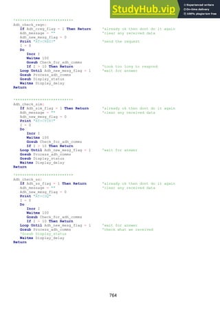
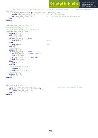
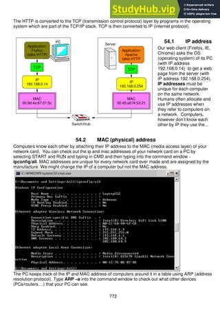
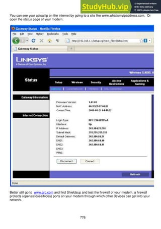
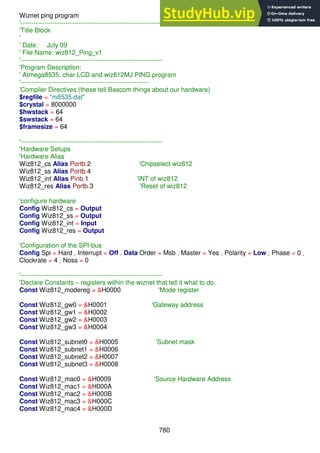
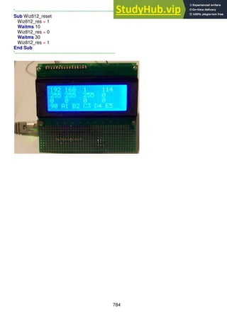
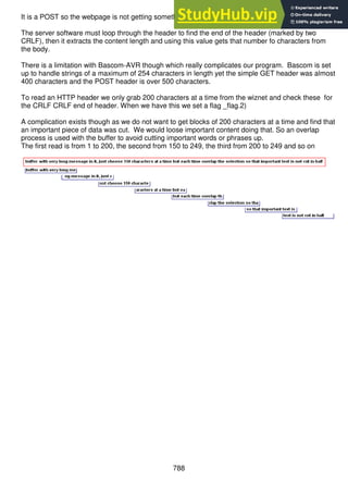
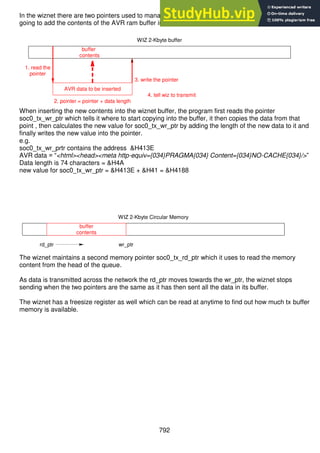
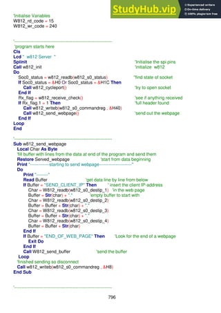
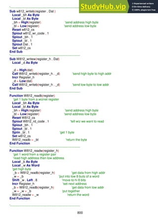
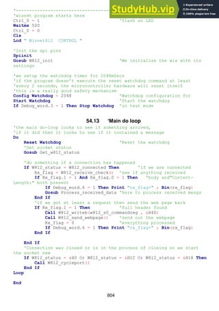
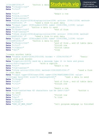
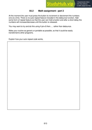
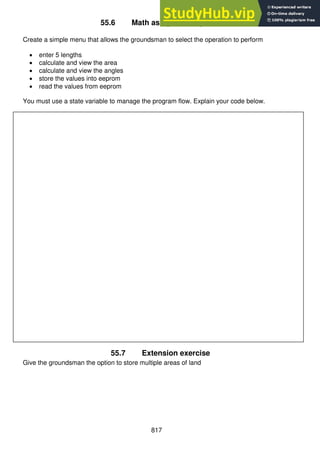
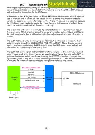
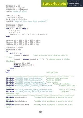
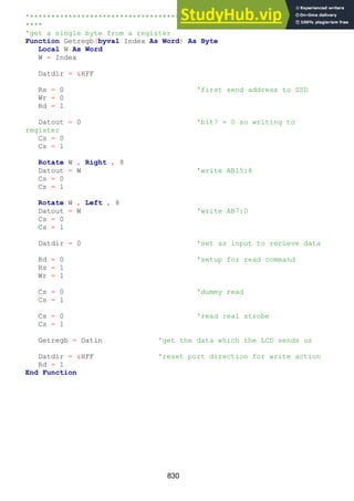
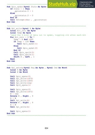
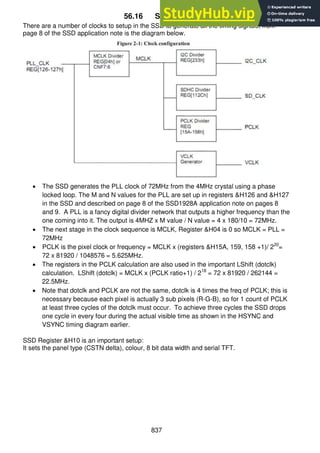
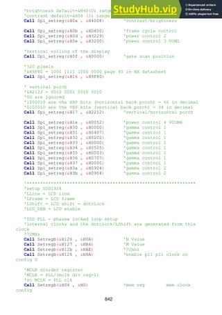
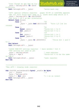
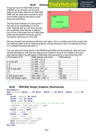
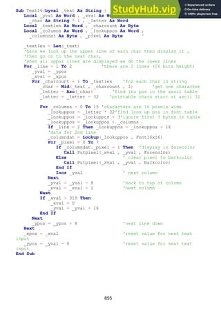
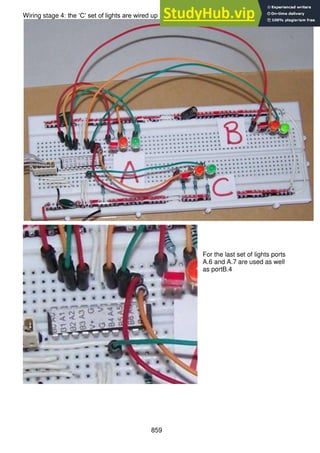
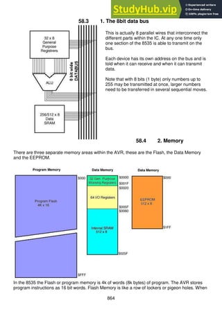
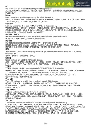
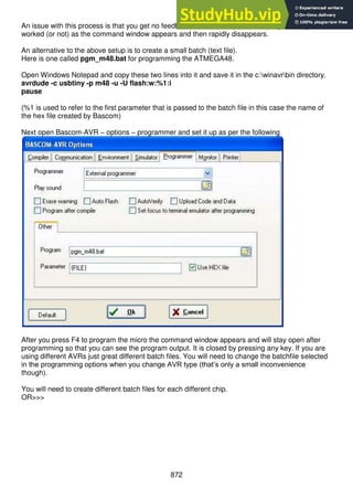
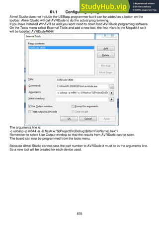
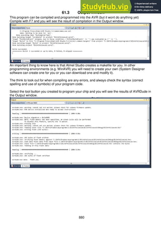
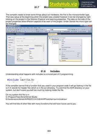
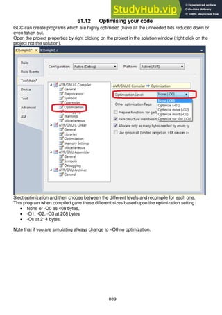
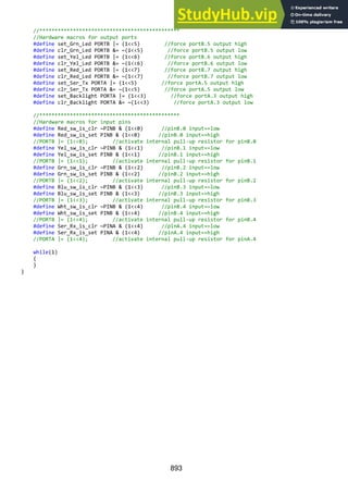
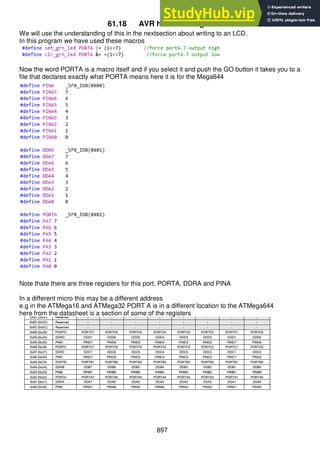
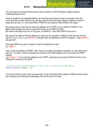
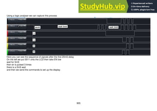
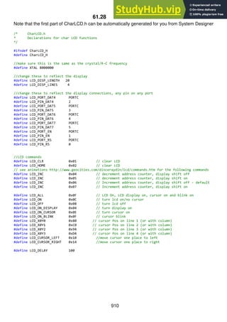
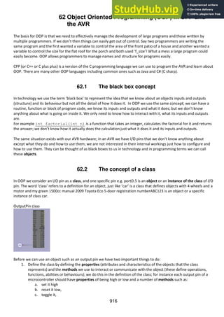
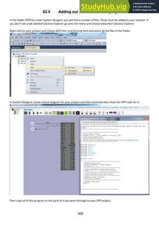
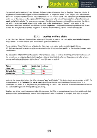
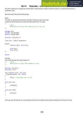
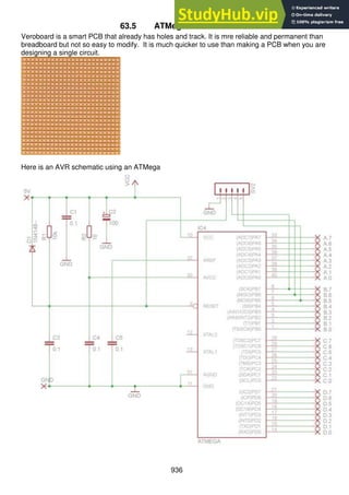
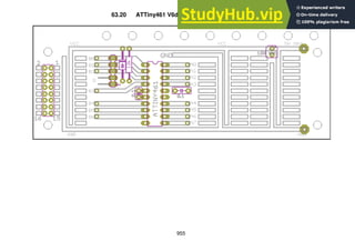
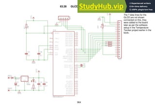
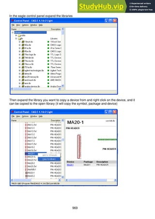
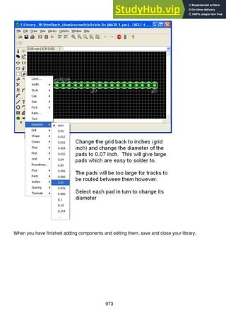
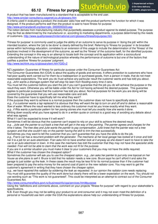
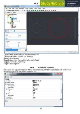
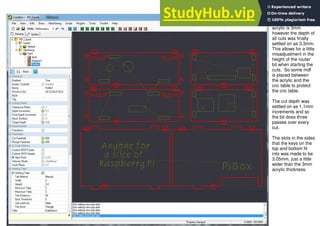
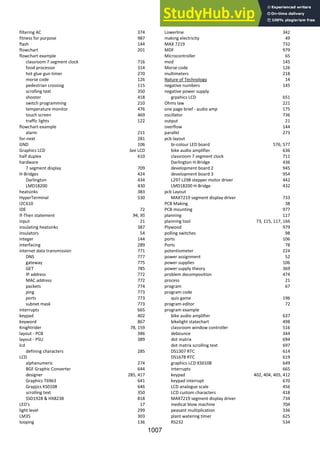
56.10 Accessing SSD control registers
The first set of subroutines we will need will allow all of our other routines to write to and read
from the control registers in the SSD1928. Addressing a register requires 3 bytes of address
to be sent to the SSD. Note that this is more than the address range of the actual registers in
the SSD which could be addressed using 2 bytes; the addressing however is the same as
that used to access the 256kbyte SRAM in the SSD1928 for pixel colour data which requires
19 bits of address [A18:A0].
To tell the difference between an address of a register and an address in memory the SSD
requires the first bit of our three bytes of address to be a 1 for memory and a 0 for a register.
e.g. &B1000 0000 0000 0000 1111 1111 is memory and &B0000 0000 0000 0000 1111
1111 is a register address.
We will need routines that can read and write 8, 16 and 32 bit data registers.
The routines we will write are:
Read a byte from a register getreg(word_addr)
Write a byte into a register setregb(word_addr, byte_data)
Read a word (2 bytes) from a register getregw(word_addr)
Write a word (2 bytes) into a register setregw(word_addr, word_data )
Read a long (4 bytes) from a register getregl(word_addr)
Write a long (4 bytes) into a register setregl(word_addr, long_data)](https://image.slidesharecdn.com/anintroductiontopracticalelectronicsmicrocontrollersandsoftwaredesign-230807154315-4eeee865/85/An-Introduction-to-Practical-Electronics-Microcontrollers-and-Software-Design-pdf-827-320.jpg)


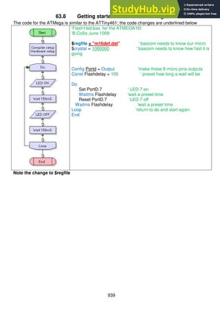
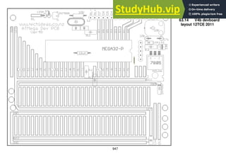
![909
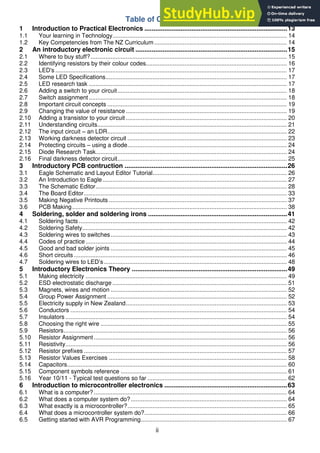
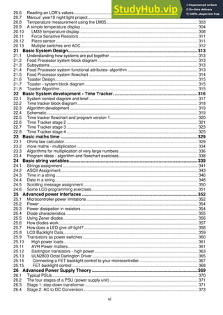
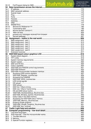
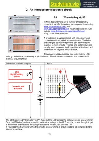
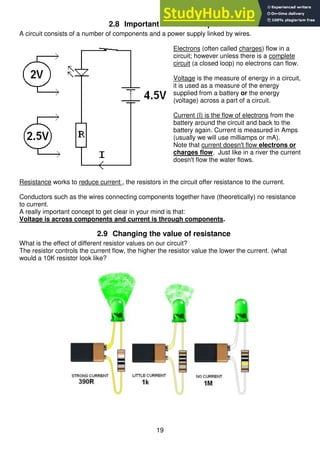
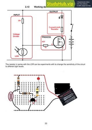
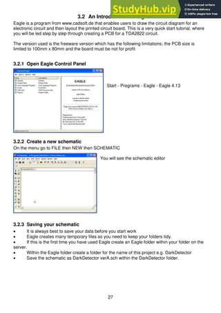
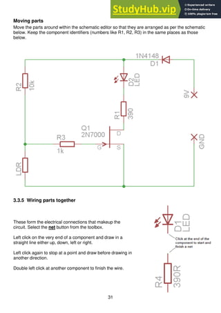
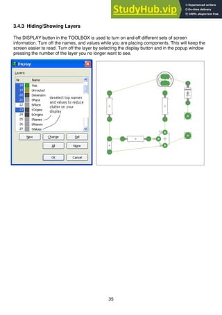
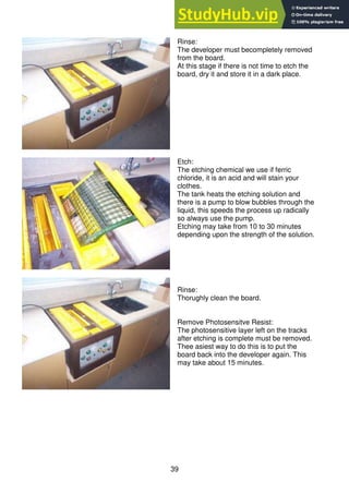
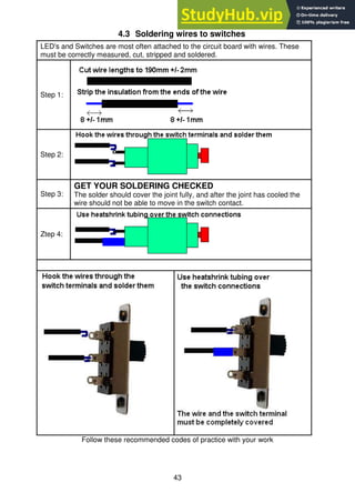
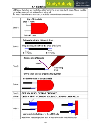
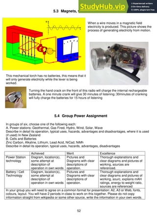
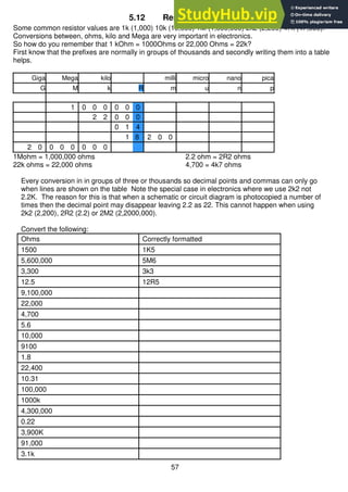
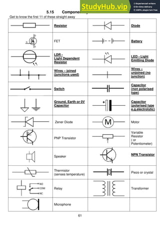
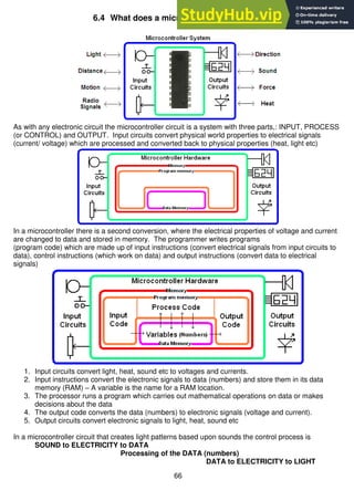
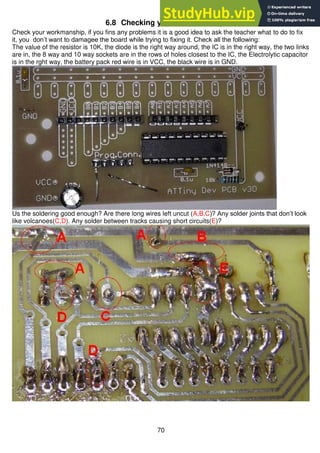
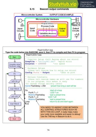
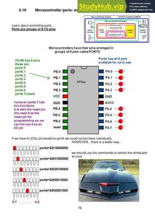
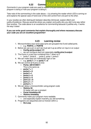
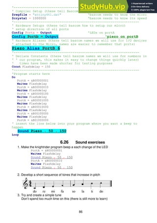
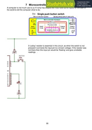
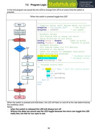
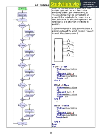
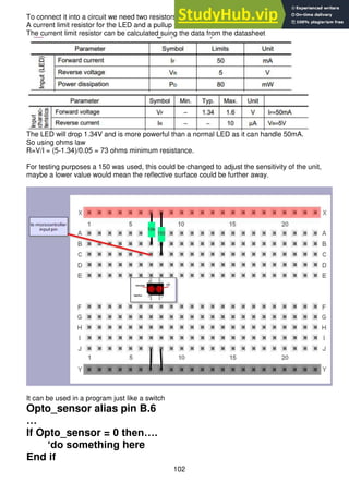
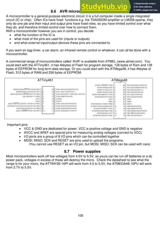
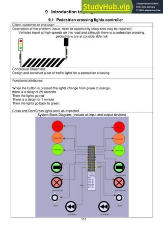
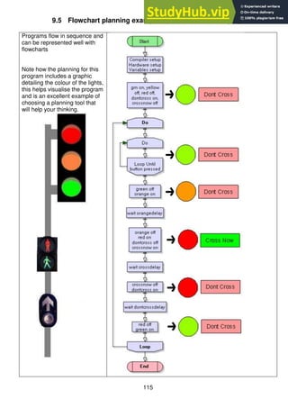
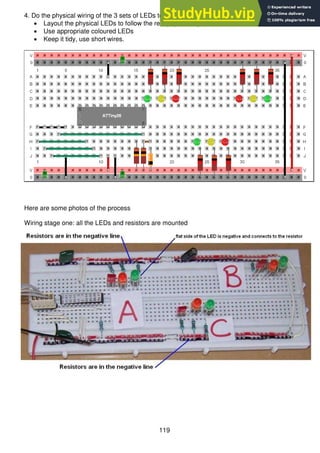
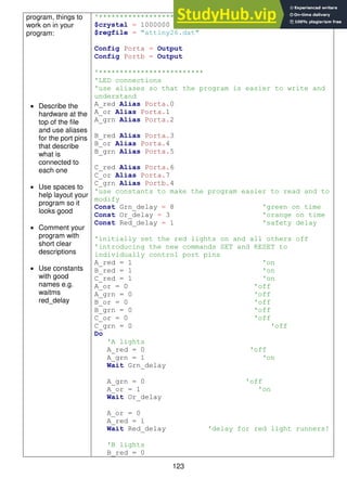
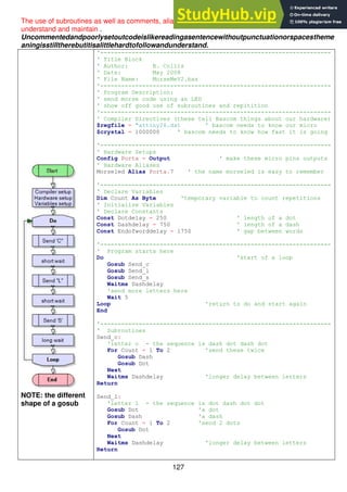
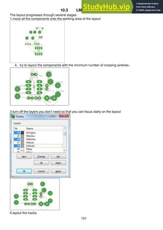
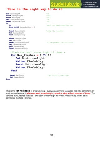
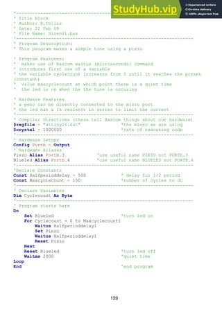
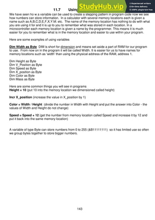
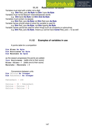
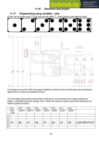
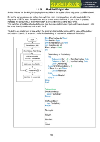
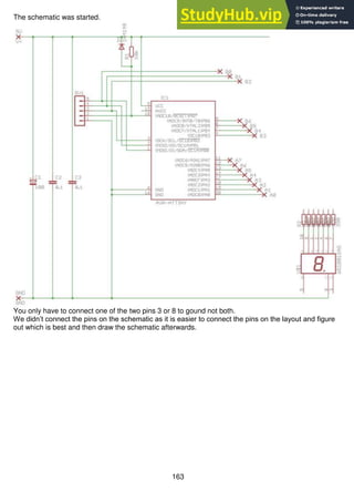
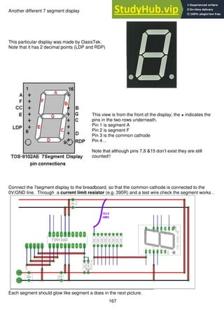
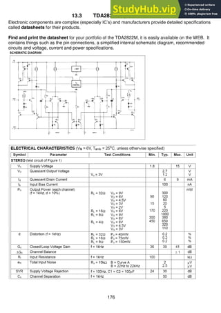
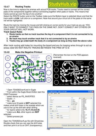
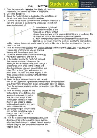
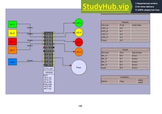
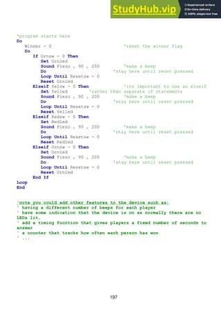
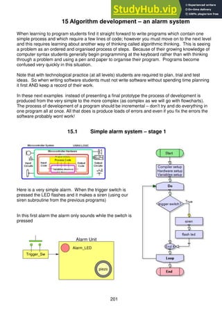
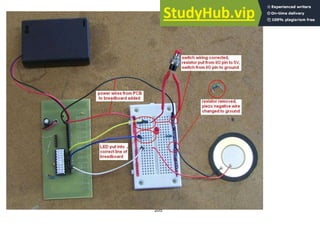
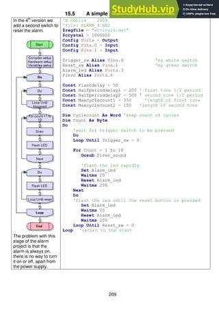
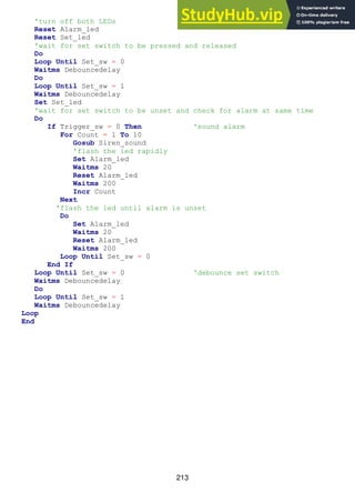
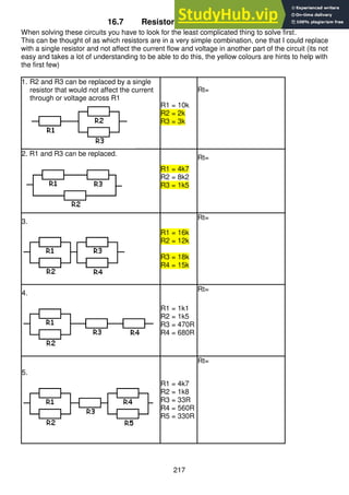
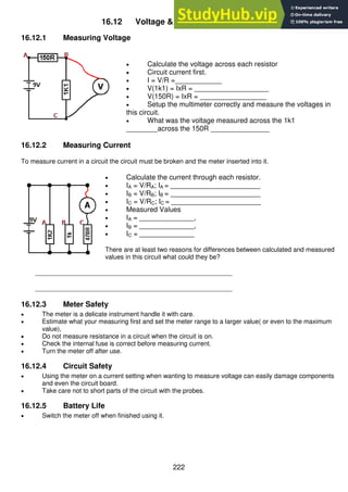
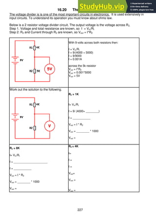
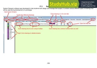
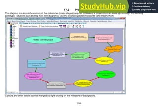
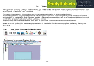
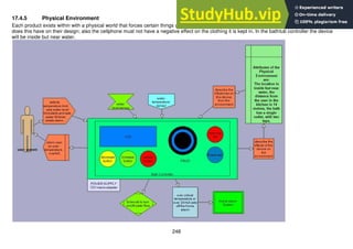
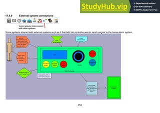
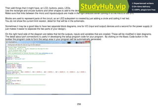
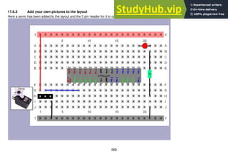
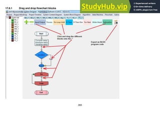
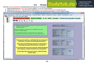
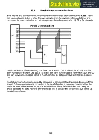
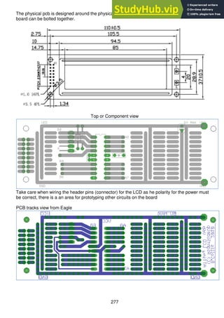
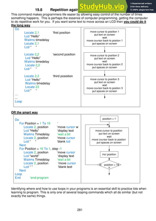
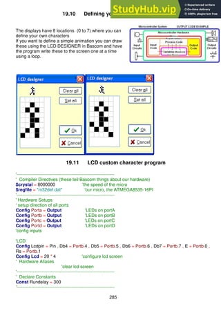
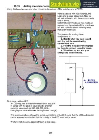
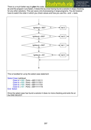
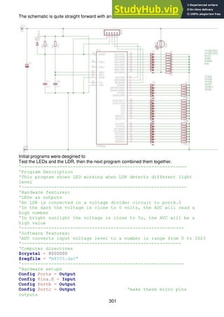
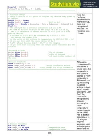
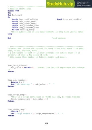
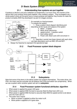
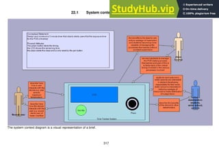
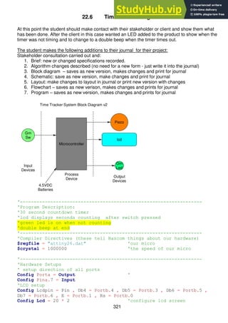
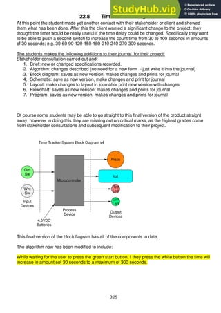
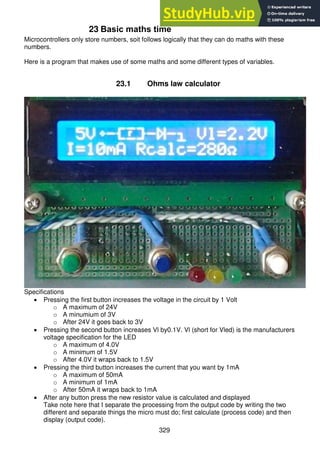
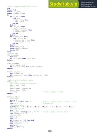
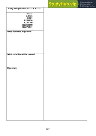
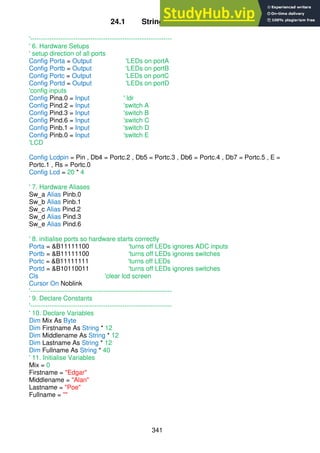
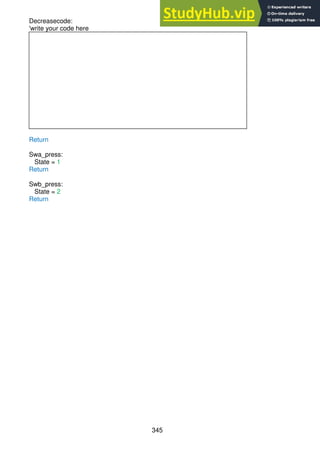
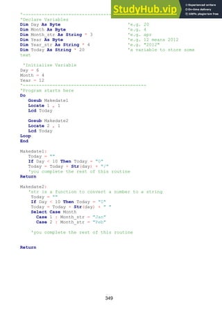
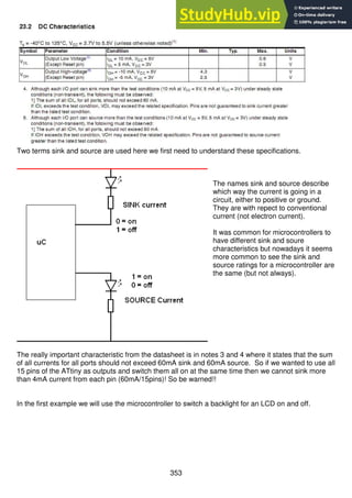
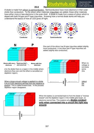
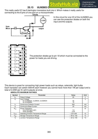
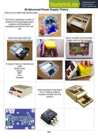
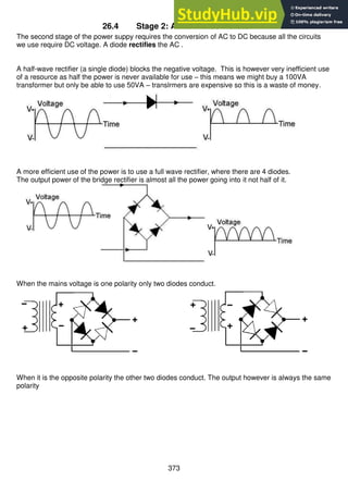
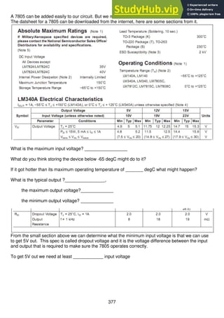
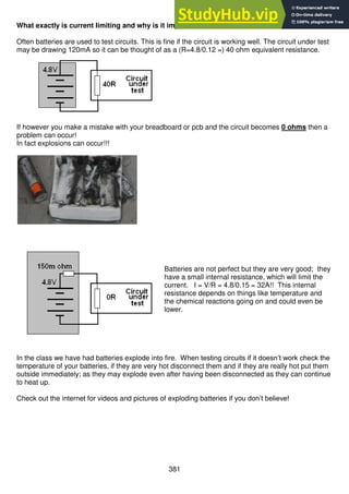
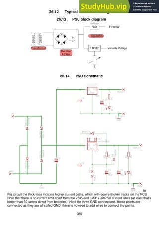
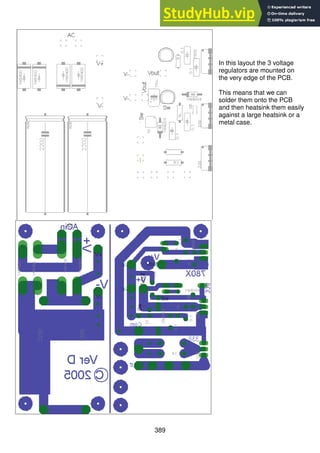
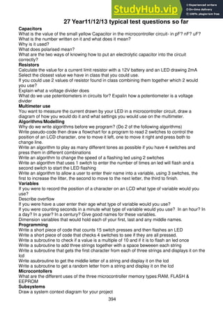
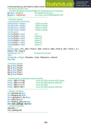
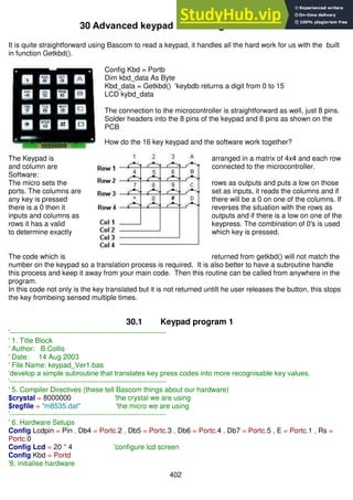
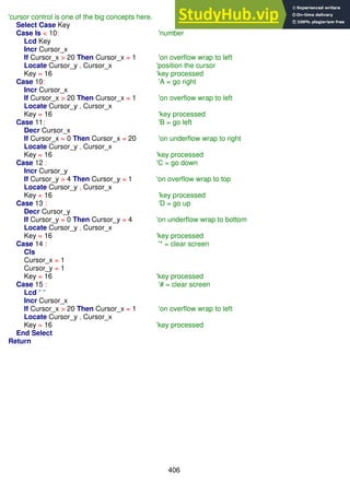
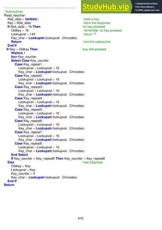
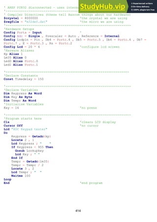
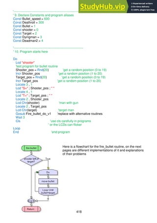
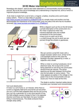
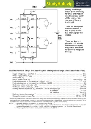
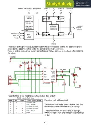
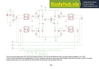
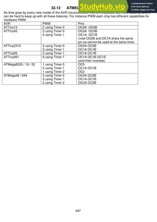
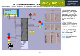
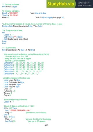
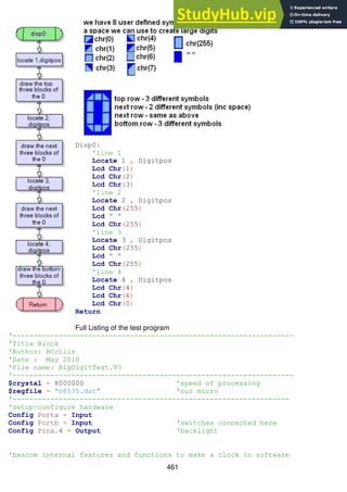
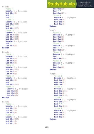
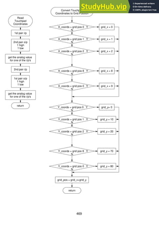
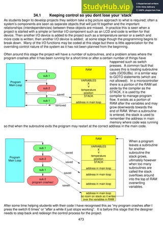
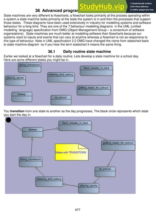
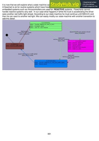
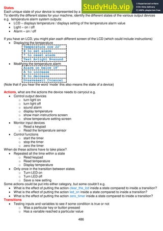
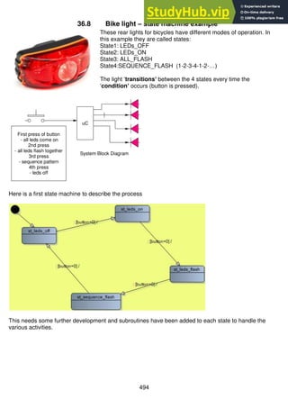
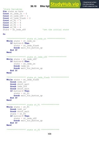
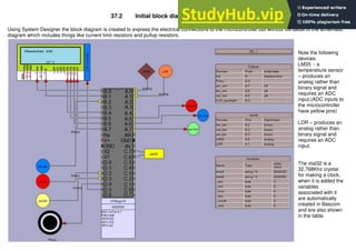
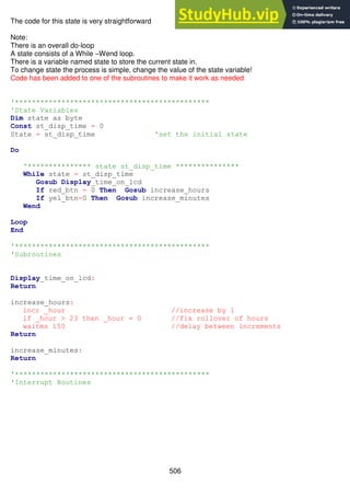
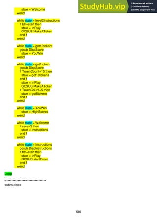
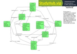
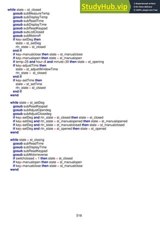
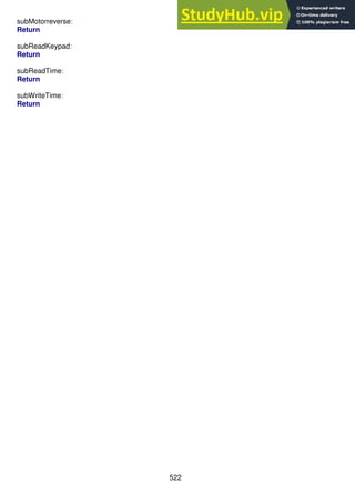
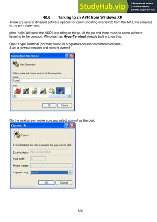
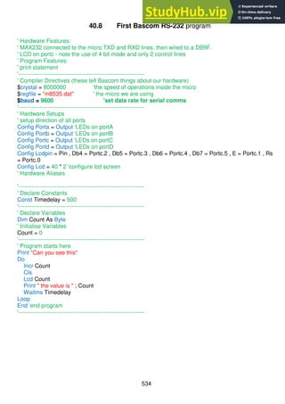
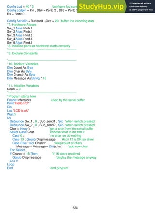
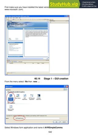
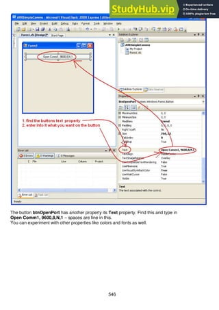
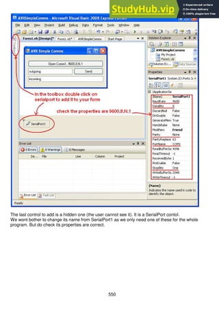
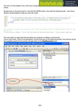
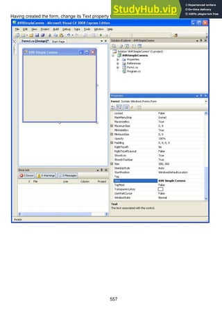
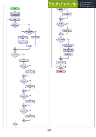
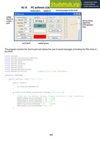
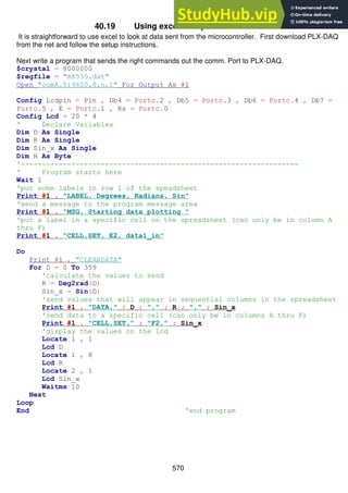
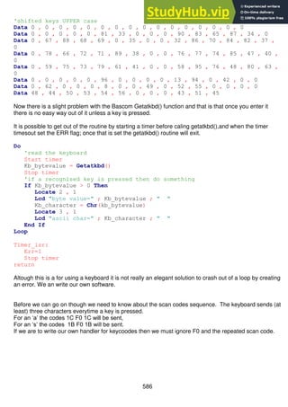
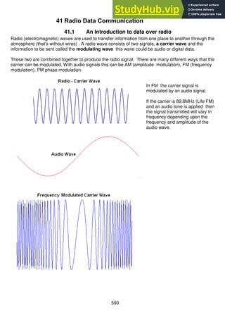
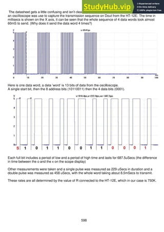
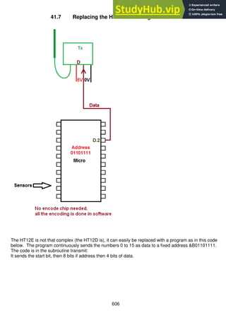
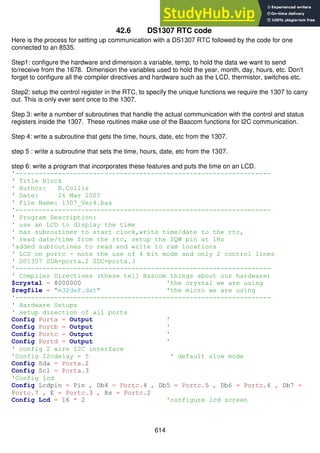
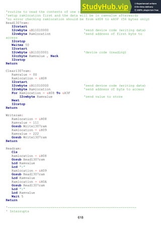
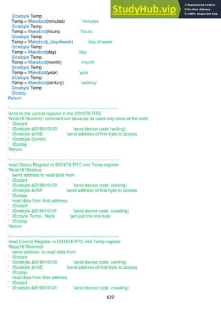
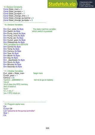
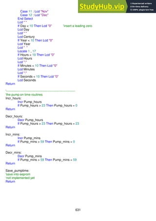
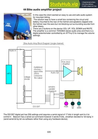
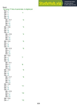
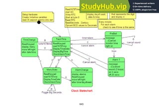
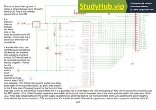
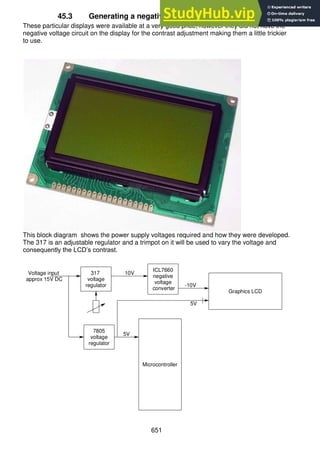
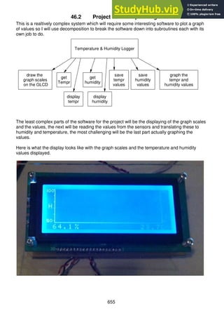
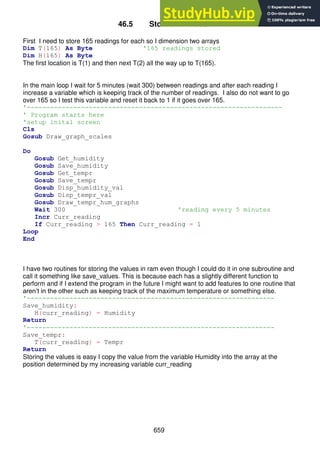
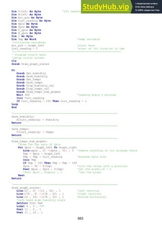
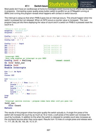
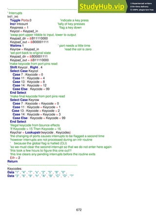
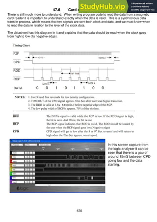
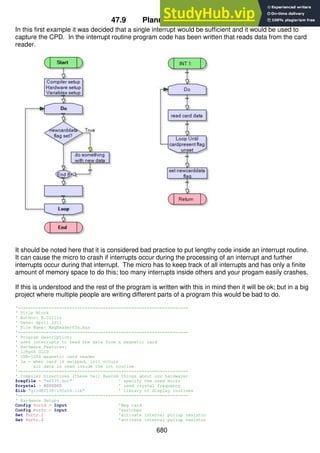
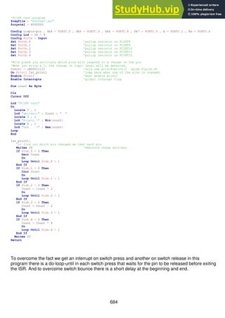
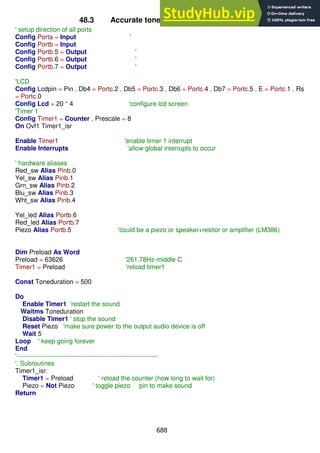
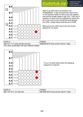
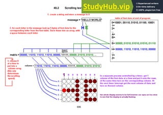
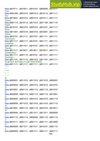
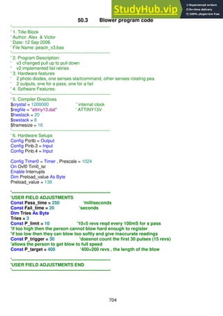
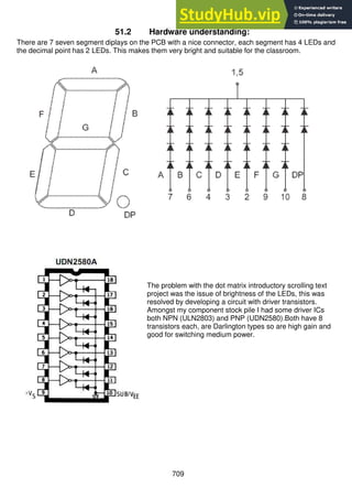
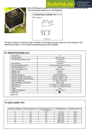
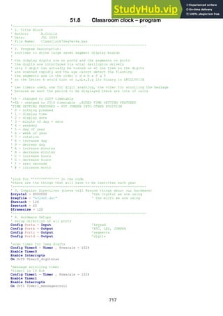
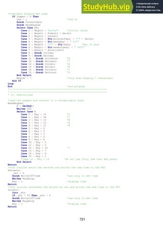
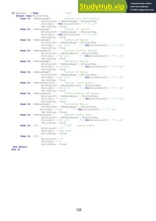
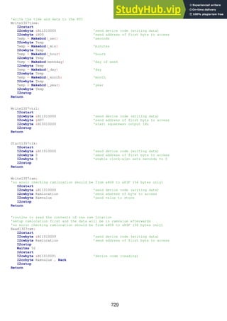
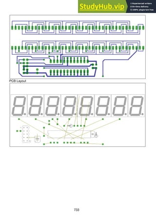
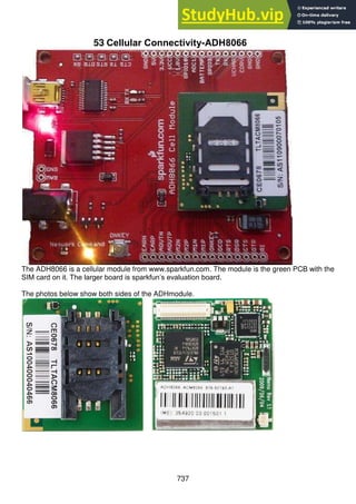
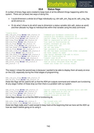
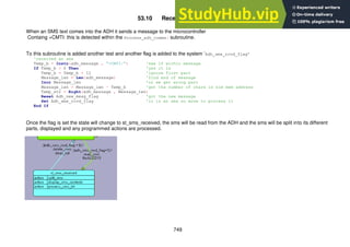
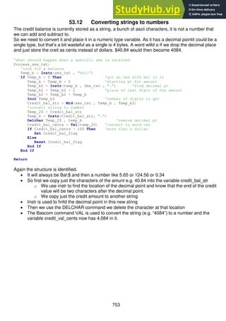
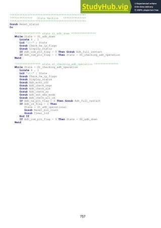
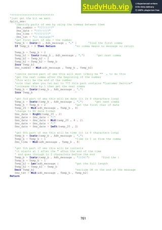
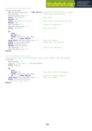
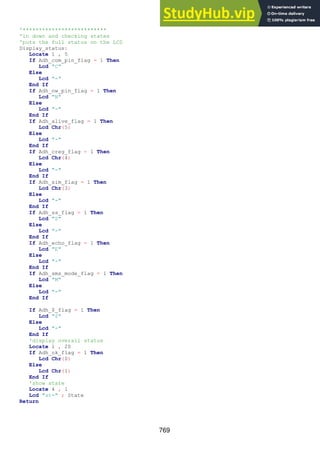
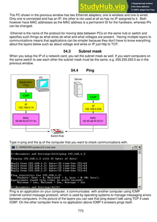
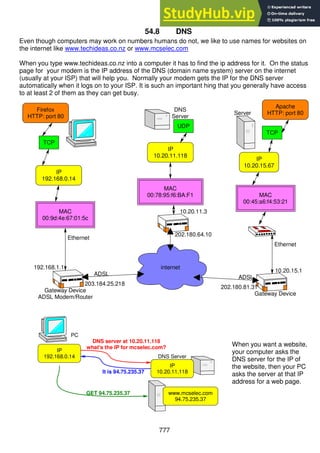
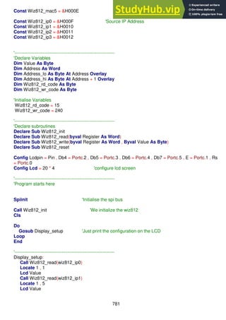
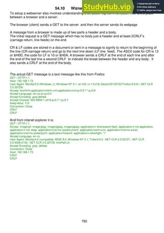
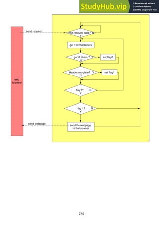
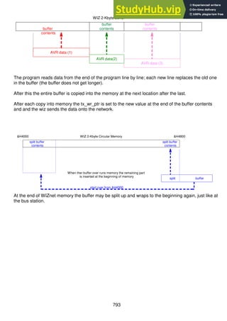
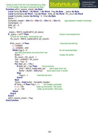
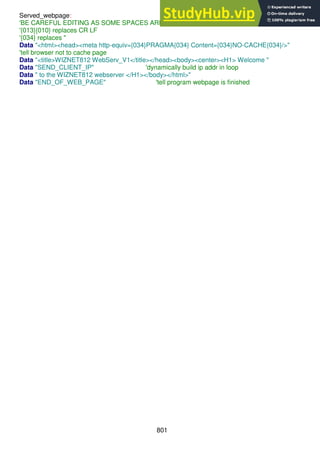
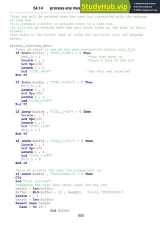
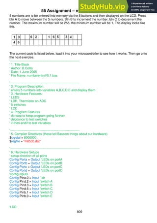
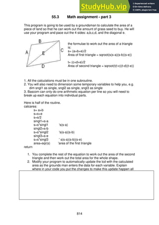
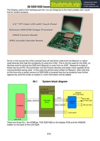
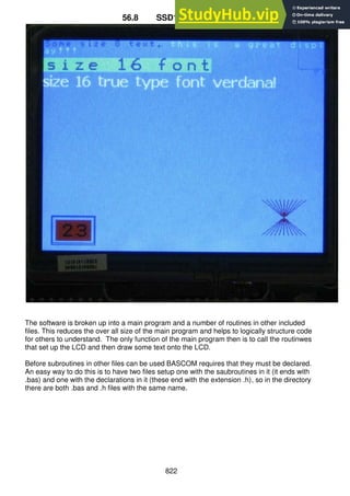
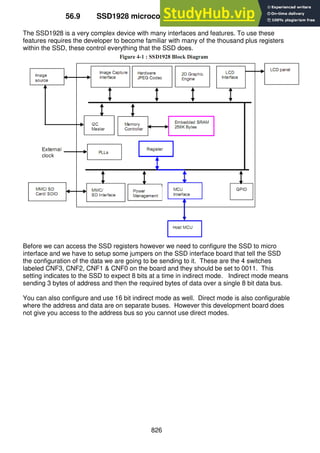
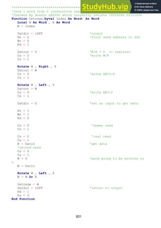
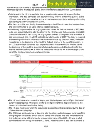
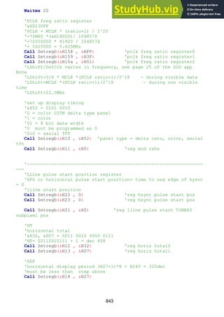
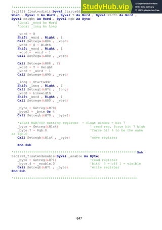
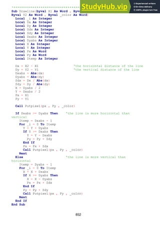
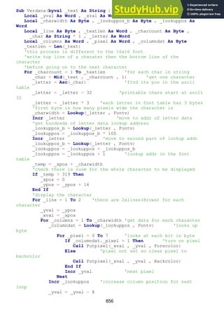
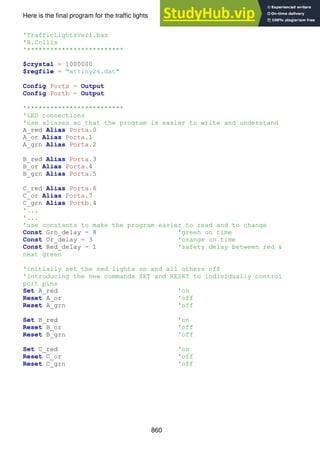
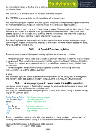
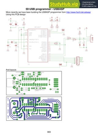
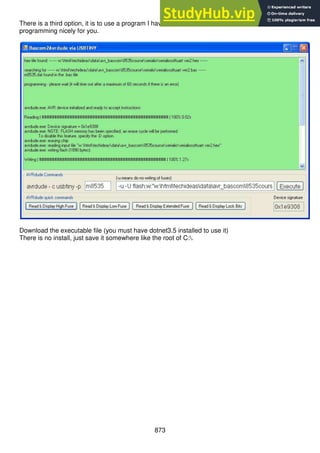
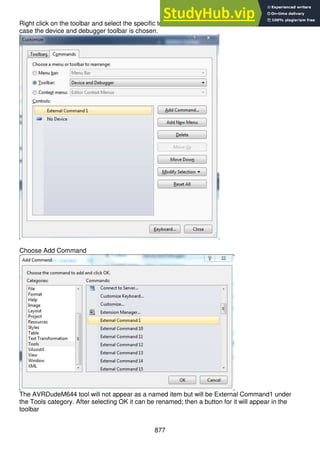
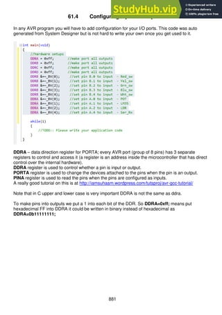
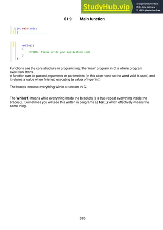
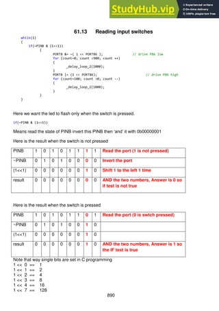
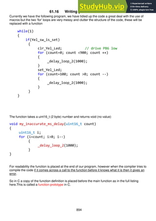
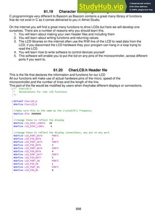
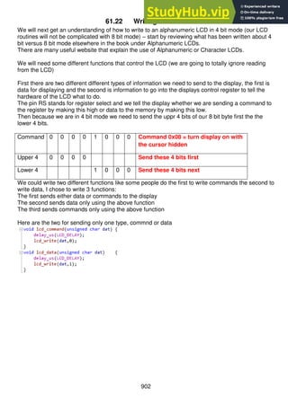
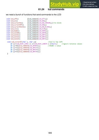
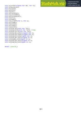
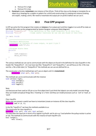
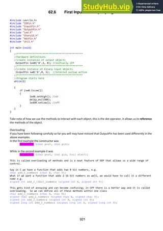
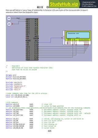
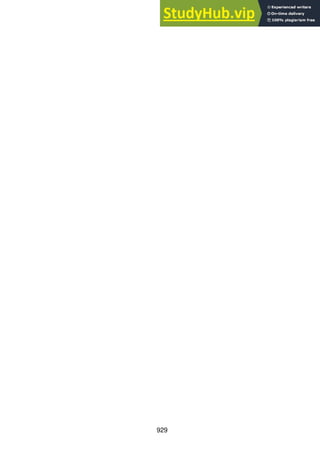
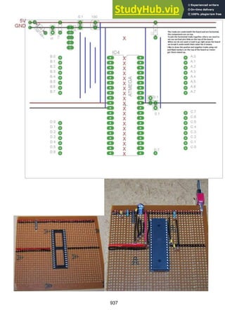
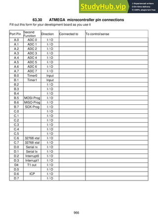
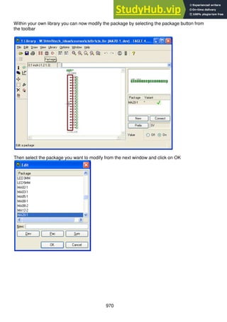
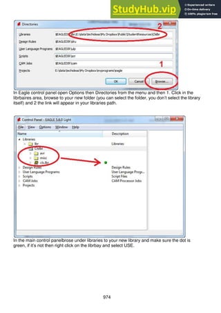
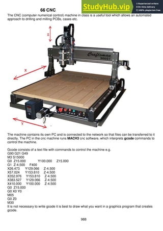
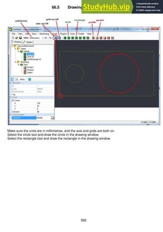
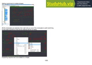
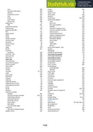
61.27 LCD test program1
/*
* LCD.c
*
* Created: 6/10/2012 8:54:41 PM
* Author: B.Collis
*/
#define F_CPU 8000000
#include <avr/io.h>
#include <avr/pgmspace.h>
#include "CharLCD.h"
#include "util/delay.h"
const char animal1[] PROGMEM= "Giraffe"; //forces storage in flash
char animal2[12]="cat"; //stored in RAM - takes 12 bytes
char* animal3="dolphin"; //stored in RAM allocates 7 bytes
char *animal4="kangaroo";
char *animal5="monkey";
//see this website for a great tutorial on using progmem
//http://www.fourwalledcubicle.com/AVRArticles.php
int main(void)
{
lcd_init();
lcd_cursorOn();
lcd_disp_str("caterpillar");//string literal or constant - copied to ram at startup
lcd_line1();
lcd_disp_str_P(animal1); //string in ram
lcd_line2();
lcd_disp_str(animal2); // string in flash
animal2[3]='y';
lcd_cursorXY(10,2);
lcd_disp_str2(animal2); //string in ram
lcd_line3();
lcd_disp_str(animal3); // string in flash
animal3[0]='D';
lcd_cursorXY(10,3);
lcd_disp_str(animal3); //string in ram
while(1)
{
_delay_ms(800);
lcd_command(LCD_CURSOR_RIGHT);
}
}](https://image.slidesharecdn.com/anintroductiontopracticalelectronicsmicrocontrollersandsoftwaredesign-230807154315-4eeee865/85/An-Introduction-to-Practical-Electronics-Microcontrollers-and-Software-Design-pdf-909-320.jpg)
![914
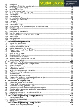
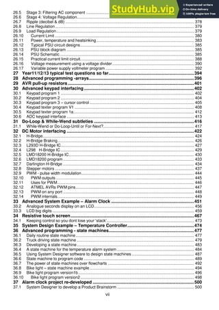
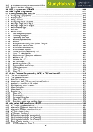
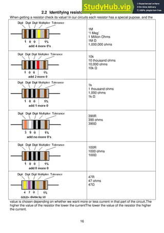
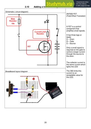
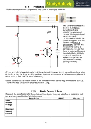
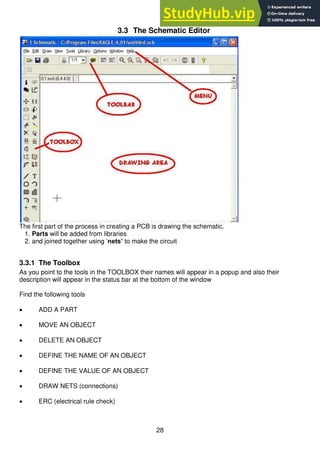
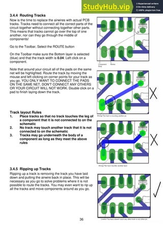
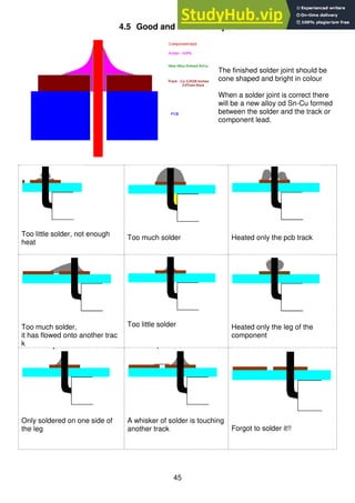
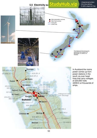
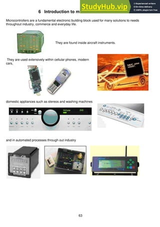
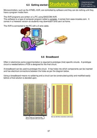
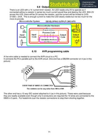
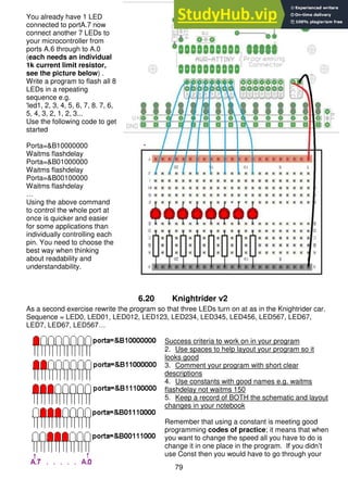
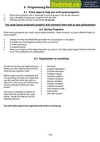
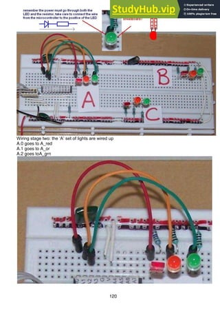
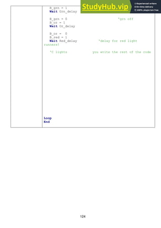
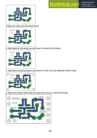
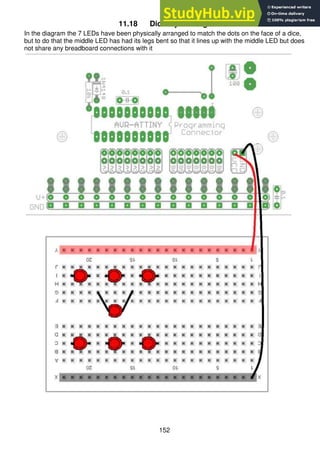
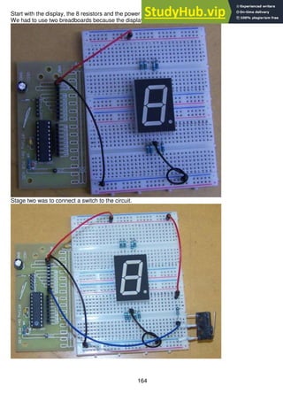
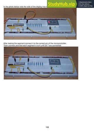
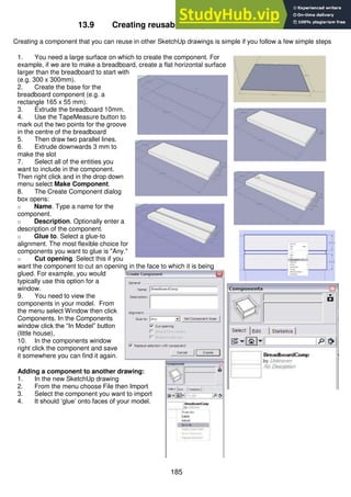
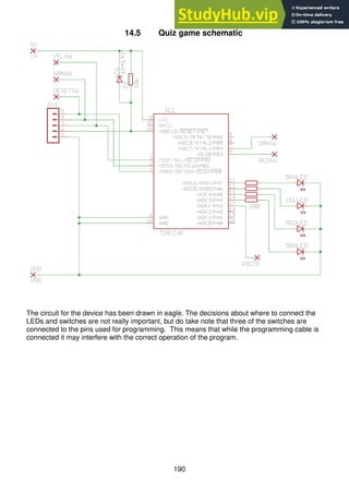
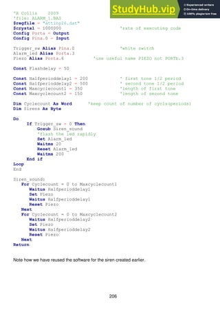
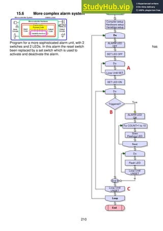
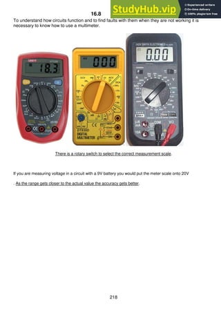
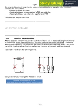
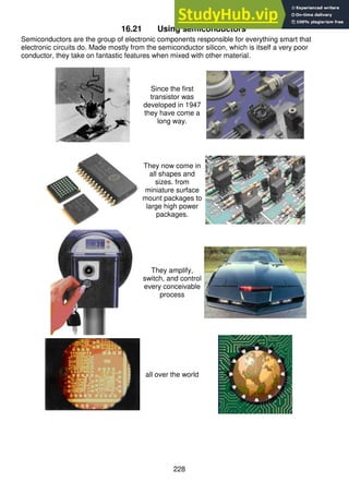
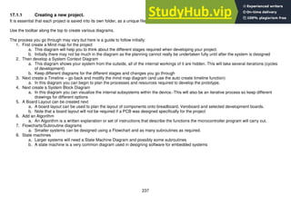
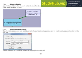
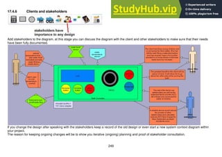
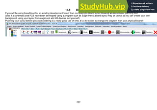
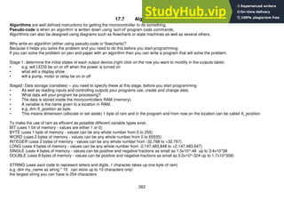
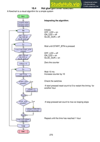
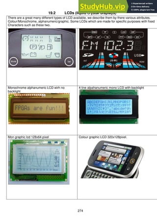
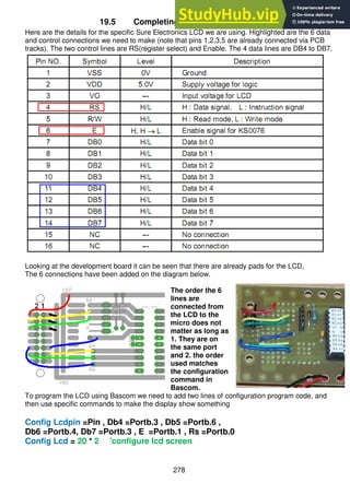
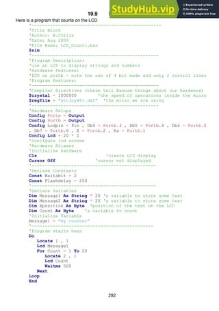
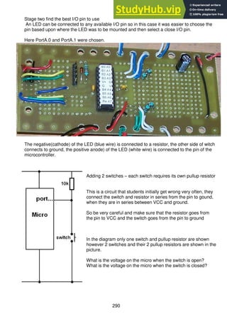
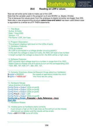
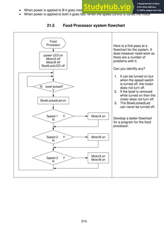
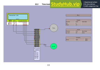
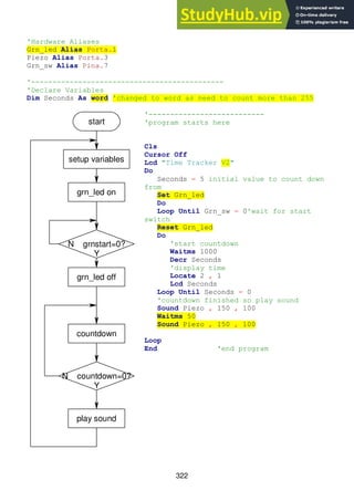
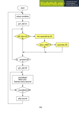
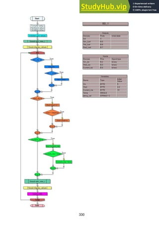
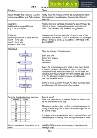
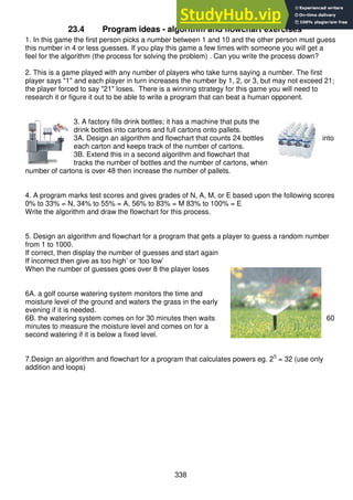
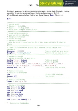
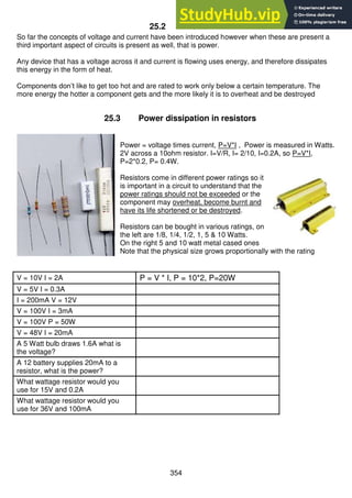
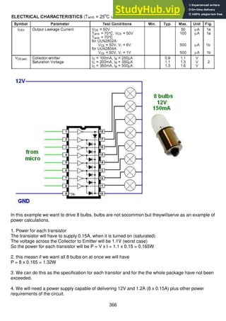
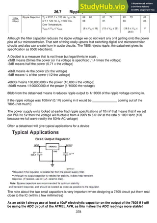
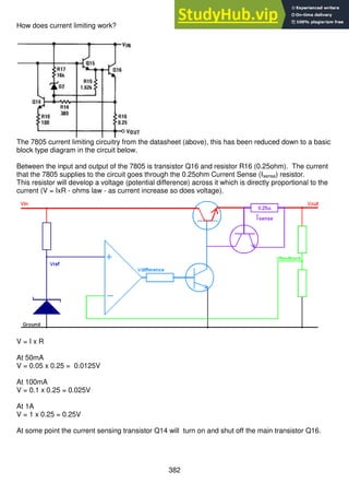
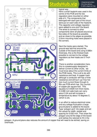
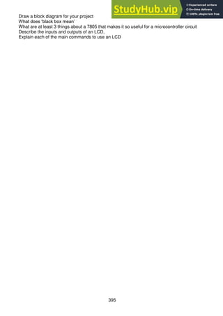
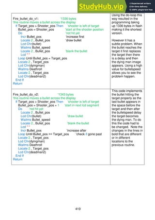
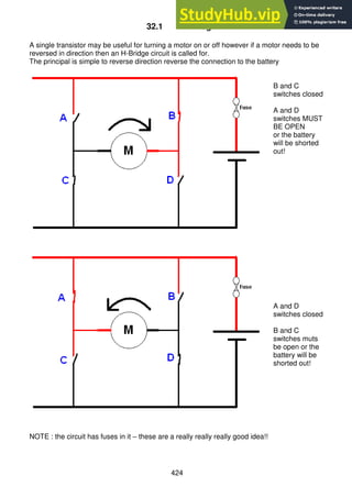
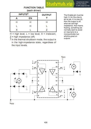
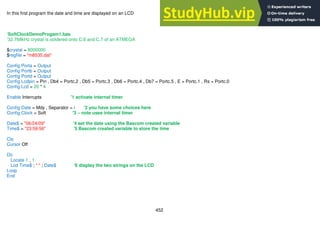
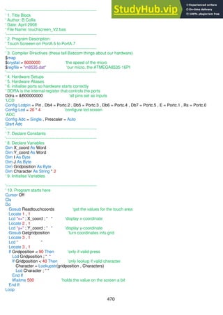
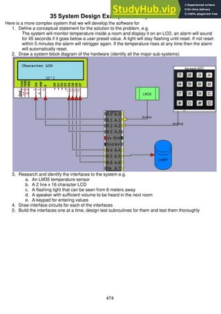
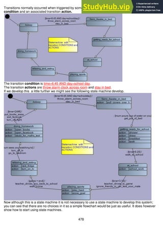
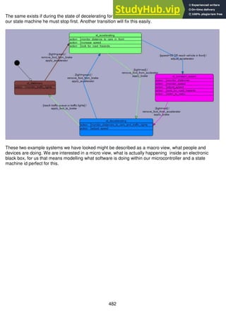
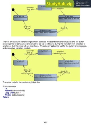
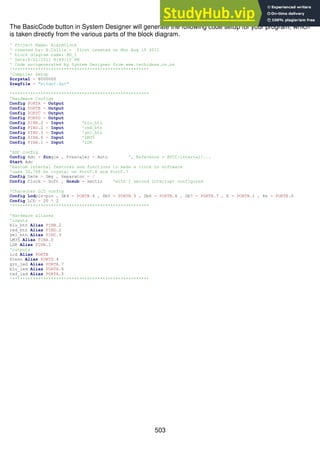
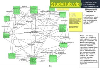
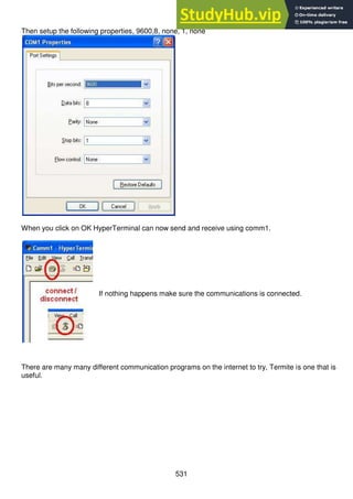
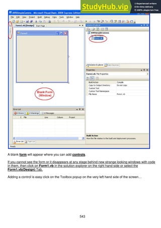
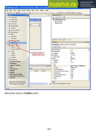
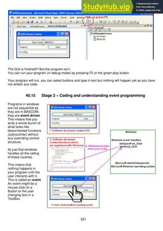
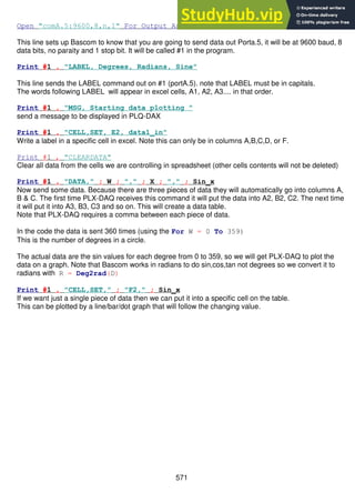
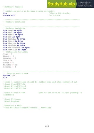
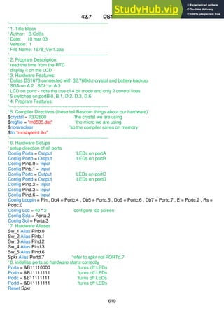
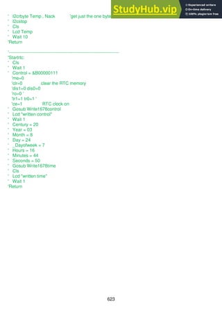
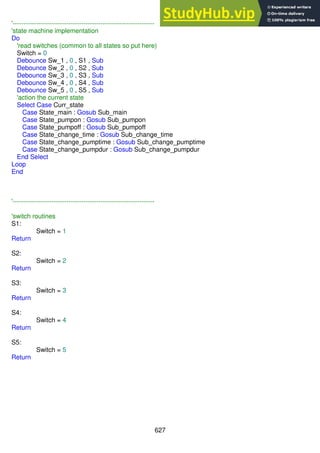
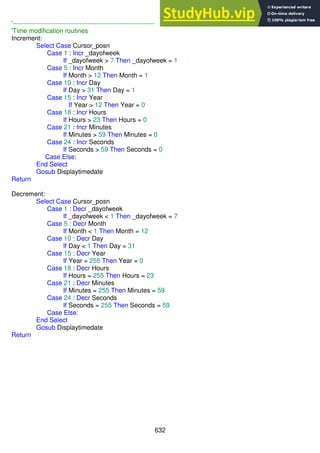
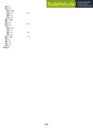
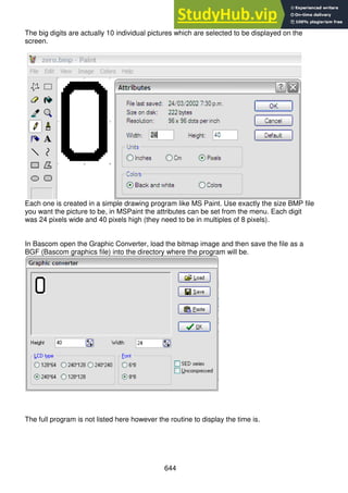
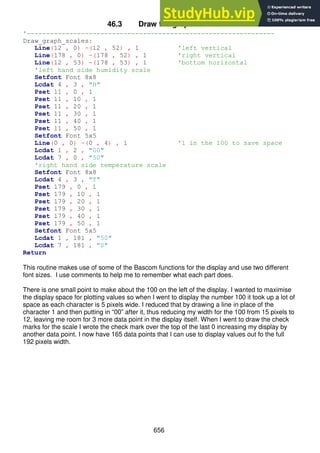
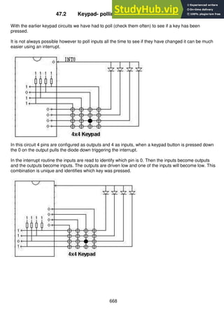
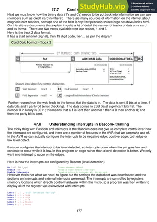
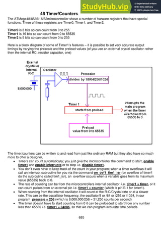
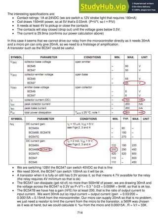
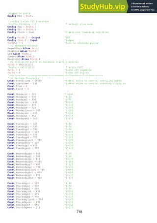
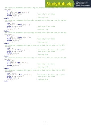
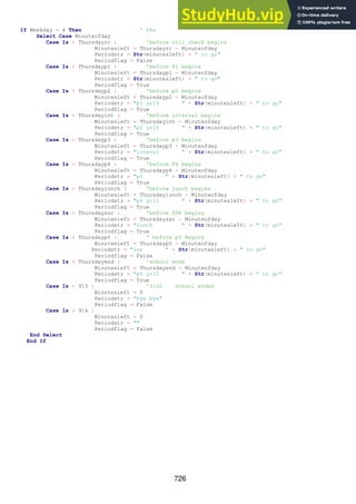
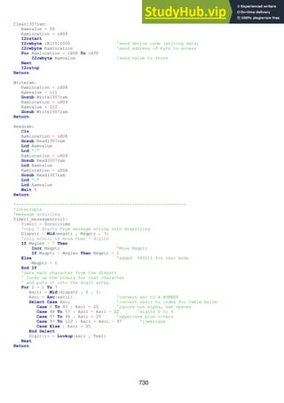
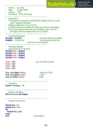
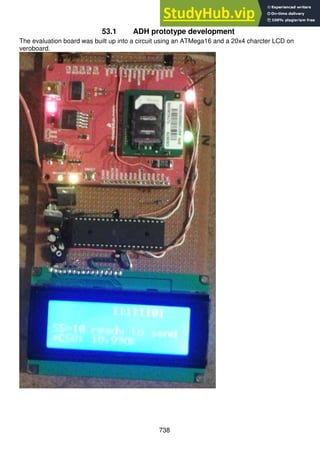
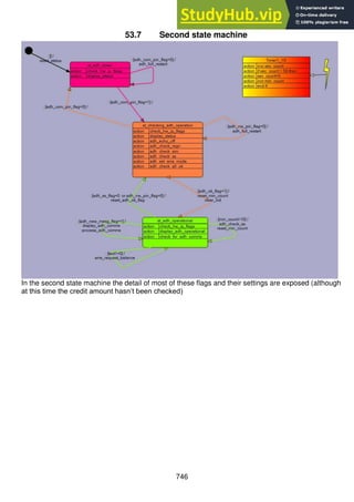
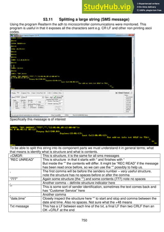
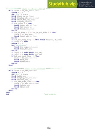
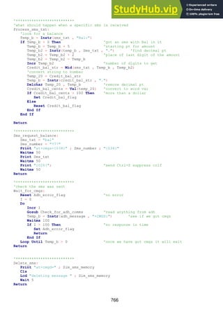
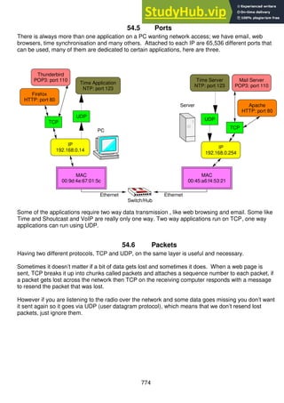
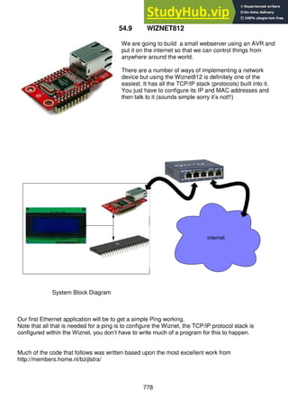
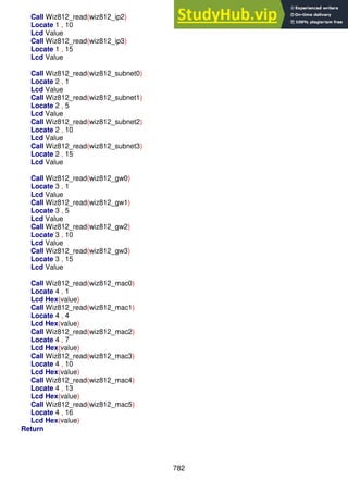
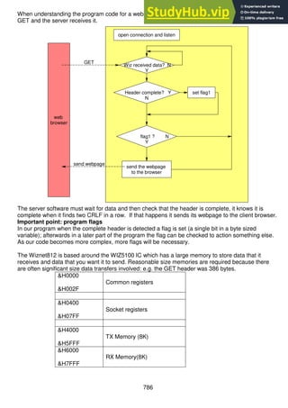
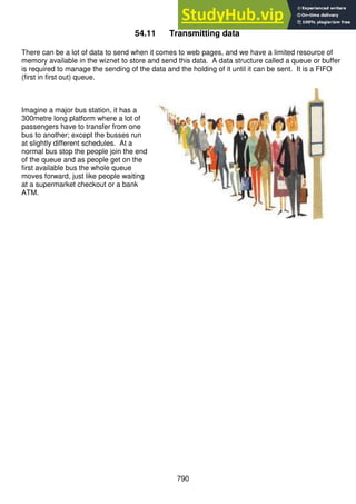
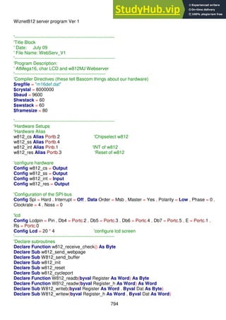
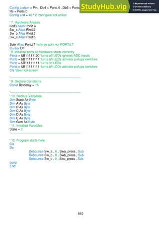
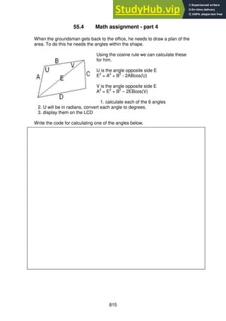
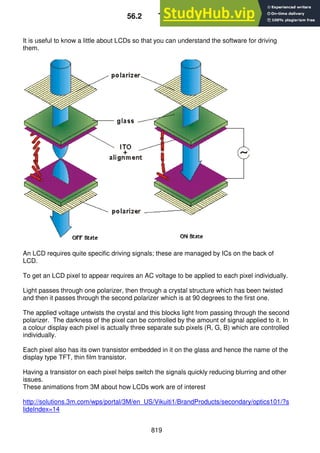
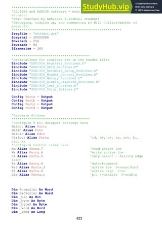
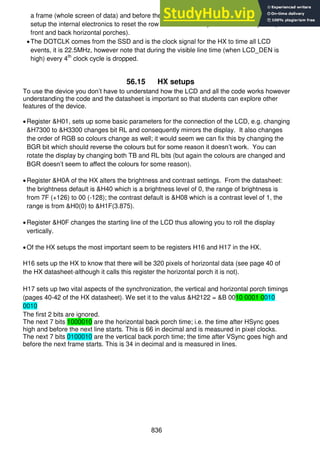
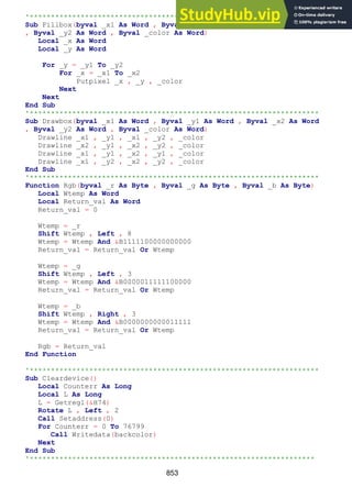
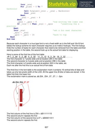
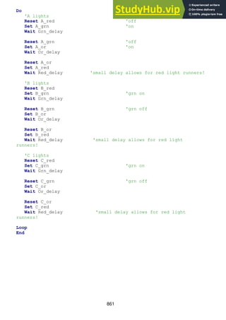
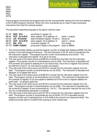
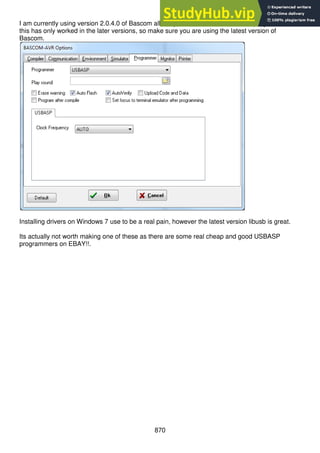
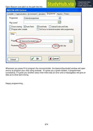
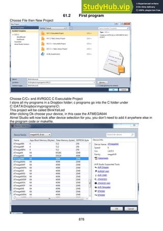
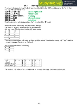
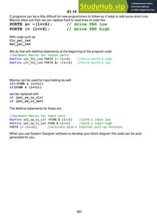
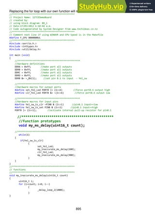
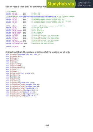
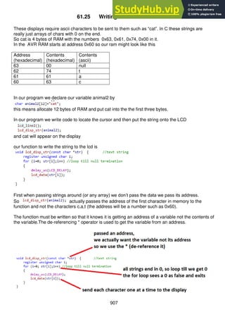
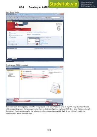
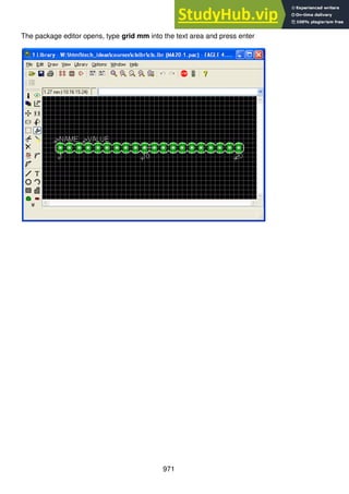
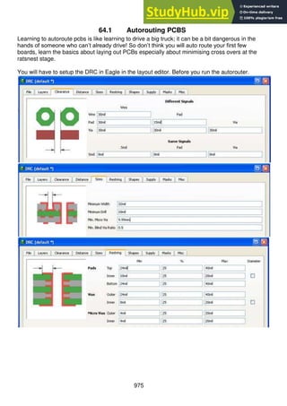
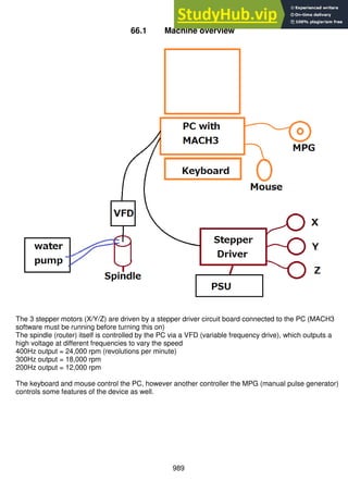
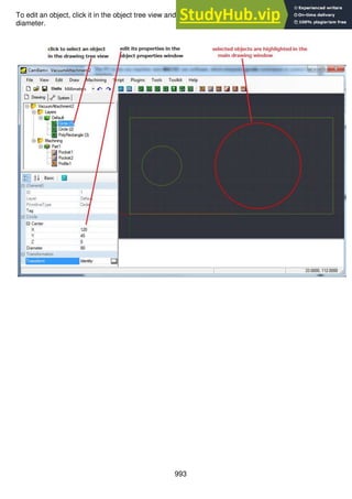
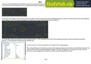
void lcd_off() {lcd_command(LCD_OFF);}
void lcd_on() {lcd_command(LCD_ON);}
void lcd_cursorOn() {lcd_command(LCD_ON_CURSOR);}//no blink
void lcd_cursorOff() {lcd_command(LCD_ON);}
void lcd_cursorBlink() {lcd_command(LCD_ON_BLINK);}
void lcd_cls() {lcd_command(LCD_CLR);}
void lcd_home() {lcd_command(LCD_HOME);}
void lcd_line0() {lcd_command(LCD_X0Y0);}
void lcd_line1() {lcd_command(LCD_X0Y1);}
void lcd_line2() {lcd_command(LCD_X0Y2);}
void lcd_line3() {lcd_command(LCD_X0Y3);}
void lcd_cursorXY(char x, char y){ //0,0 is top left
if (y>=LCD_DISP_LINES || x>=LCD_DISP_LENGTH ) {return;} //ignore nonsense values
if (y==0){lcd_command(LCD_X0Y0+x);} //0x80+ x value
if (y==1){lcd_command(LCD_X0Y1+x);}
if (y==2){lcd_command(LCD_X0Y2+x);}
if (y==3){lcd_command(LCD_X0Y3+x);}
}
void lcd_disp_str(const char *str) { //text string
register unsigned char i;
for (i=0; str[i];i++) //loop till null termination
{
delay_us(LCD_DELAY);
lcd_data(str[i]);
}
}
void lcd_disp_str2(const char *str) { //text string
register unsigned char c;
while ((c=*str++)){ //get contents of str then incr str
delay_us(LCD_DELAY);
lcd_data(c);
}
}
void lcd_disp_str_P(const char *str) { //text string
register unsigned char i;
for (i=0; (char)pgm_read_byte(&str[i]);i++) //loop till null termination
{
delay_us(LCD_DELAY);
lcd_data((char)pgm_read_byte(&str[i]));
}
}](https://image.slidesharecdn.com/anintroductiontopracticalelectronicsmicrocontrollersandsoftwaredesign-230807154315-4eeee865/85/An-Introduction-to-Practical-Electronics-Microcontrollers-and-Software-Design-pdf-914-320.jpg)
![915
void lcd_disp_dec_uchar(unsigned char n) { //0 to 255
char buffer[3];
itoa (n, buffer,10); //decimal display of
lcd_disp_str(buffer);
}
void lcd_disp_bin_uchar(unsigned char n) { //0 to 255
char buffer[8];
itoa (n, buffer,2); //binary display of
lcd_disp_str(buffer);
}
void lcd_disp_bin_schar(signed char n) { //0 to 255
char buffer[8];
itoa (n, buffer,2); //binary display of
lcd_disp_str(buffer);
}
void lcd_disp_dec_uint(unsigned int n) { //- to
char buffer[7];
itoa (n, buffer,10); //decimal display
lcd_disp_str(buffer);
}
void lcd_dispdec_sint(signed int n) { //- to
char buffer[7];
itoa (n, buffer,10); //decimal display
lcd_disp_str(buffer);
}
void lcd_disp_bin_unit(unsigned int n) { //- to
char buffer[16];
itoa (n, buffer,2); //binary display
lcd_disp_str(buffer);
}
void lcd_disp_bin_sint(signed int n) { //- to
char buffer[16];
itoa (n, buffer,2); //binary display
lcd_disp_str(buffer);
}
void lcd_command(unsigned char dat) {
delay_us(LCD_DELAY);
lcd_write(dat,0);
}
void lcd_data(unsigned char dat) {
delay_us(LCD_DELAY);
lcd_write(dat,1);
}](https://image.slidesharecdn.com/anintroductiontopracticalelectronicsmicrocontrollersandsoftwaredesign-230807154315-4eeee865/85/An-Introduction-to-Practical-Electronics-Microcontrollers-and-Software-Design-pdf-915-320.jpg)


This document provides an introduction to practical electronics, microcontrollers, and software design across 24 chapters. It covers topics such as introductory circuits, programming, microcontrollers, interfaces, analog to digital conversion, system design, and more. Each chapter includes explanations of concepts, examples, assignments, and exercises to help learn and reinforce the material.


![Embedded System[586]](https://cdn.slidesharecdn.com/ss_thumbnails/viisemesterindustrialtrainingreportpawan586-171104035355-thumbnail.jpg?width=640&height=640&fit=bounds)


![Robotics & Embedded IoT System Design [Day-1]](https://cdn.slidesharecdn.com/ss_thumbnails/roboticsiot-1-170621102837-thumbnail.jpg?width=640&height=640&fit=bounds)


