This article presents an improved 2×2 array antenna utilizing both-sided microwave integrated circuit technology for achieving circular polarization. The proposed design features a triple feed network that enhances gain and allows for efficient impedance matching, resulting in an axial ratio of 0.7 dB and a gain of 12 dBi at an operating frequency of 10 GHz. Simulations indicate that the antenna has a bandwidth of 430 MHz with excellent reflection coefficient parameters, making it suitable for microwave communication applications.
![International Journal of Electrical and Computer Engineering (IJECE)
Vol. 13, No. 1, February 2023, pp. 619~628
ISSN: 2088-8708, DOI: 10.11591/ijece.v13i1.pp619-628 619
Journal homepage: http://ijece.iaescore.com
An improved 2×2 array antenna using both-sided microwave
integrated circuit technology for circular polarization
Piyas Chowdhury1
, Nishako Chakma1
, Abu Hena Murshed1
, Md. Azad Hossain1
,
Quazi Delwar Hossain2
1
Department of Electronics and Telecommunication Engineering, Chittagong University of Engineering and Technology,
Chittagong, Bangladesh
2
Department of Biomedical Engineering, Chittagong University of Engineering and Technology, Chittagong, Bangladesh
Article Info ABSTRACT
Article history:
Received Feb 7, 2022
Revised Sep 26, 2022
Accepted Oct 7, 2022
A circularly polarized microstrip patch array antenna using both-sided
microwave integrated circuit (MIC) technology with a triple feed network
has been proposed in this article. The antenna elements, feed structure and
both-sided MIC technology are used and arranged in such a way to obtain
circular polarization alongside high gain without using an external matching
circuit. The 50 Ω microstrip line is used to energize the antenna where the
antenna’s total feed network is made up of both series and parallel
combinations of microstrip and slot line. The antenna was realized using
Teflon glass fiber substrate (εr)=2.15 with a thickness of 0.8 mm. The
antenna has some splendid parameters including S11 of less than -35 dB, a
gain of 12 dBi with an omnidirectional pattern and an axial ratio of 0.7 dB at
the operating frequency. The antenna possesses a bandwidth of 430 MHz
(4.22%) after operating at X-band in the frequency spectrum. The antenna’s
simulated parameters were investigated with the help of advanced design
system (ADS) simulation software in microwave momentum mode.
Keywords:
Axial ratio
Both-sided microwave
integrated circuit
Polarization
Radio frequency signal
Reflection coefficient
Triple feed This is an open access article under the CC BY-SA license.
Corresponding Author:
Md. Azad Hossain
Department of Electronics and Telecommunication Engineering, Chittagong University of Engineering and
Technology
Kaptai, Highway Raozan Pahartali Road, Chittagong- 4349
Email: azad@cuet.ac.bd
1. INTRODUCTION
Since last few decades, microstrip antenna [1]–[40] and microstrip patch array antenna has received
attention in microwave communication technology for its compact lightweight weight, low volume, low cost,
easy fabrication and compatibility with integrated circuits [1]. Though the technique is feasible for both
linear and circular polarization (CP), circular polarization is promptly designed for its special features over
linearly polarized antenna. Usually, linearly polarized antennas are easy to design and require transmit and
receive antennas to be in same polarization, but circular polarized antenna emerge better flexibility on the
orientation of the receiver antenna with respect to the transmit antenna [2]. Circular polarized antennas are
more preferable due to their intrinsic proficiencies of reducing multi-path fading, improvement in coverage
area and fixed polarization [3]. For immunes to Faraday rotation, circular polarized antennas are used in
almost all Earth-satellite communication systems [4]–[6].
Generation of circular polarized electromagnetic waves in antenna involves provoking two equal
amplitude orthogonal degenerate modes. The excitation position alongside with excitation technique of an
antenna decides the impedance bandwidth of the antenna. The usable bandwidth of a CP patch antenna is the
overlapping bandwidth of impedance bandwidth (VSWR<2 or S11<-10 dB) and axial ratio bandwidth](https://image.slidesharecdn.com/v6227398emr26sep227feb22ff-221121065035-694b0dbc/85/An-improved-2x2-array-antenna-using-both-sided-microwave-integrated-circuit-technology-for-circular-polarization-1-320.jpg)
![ ISSN: 2088-8708
Int J Elec & Comp Eng, Vol. 13, No. 1, February 2023: 619-628
620
(AR<3 dB). To meet this requirement there is various approaches have been emerged in recent days to create
CP where the same phenomena are inherent of creating orthogonal degenerate mode behind every approach
that is applied on the patch including single, dual feed, and sequential feed. The single feeding technique
includes numerous current perturbation techniques like incorporating cross slots [7], slits [8], stubs [9], spur
lines and truncated corners [10]. The coaxial feed technique also can be considered as a simple technique
under a single feed mechanism for creating CP and proposed in recent years [9]–[11]. This simple technique
suffers from low impedance and axial ratio (AR) bandwidth response. Murshed et al. [7] proposes a
reconfigurable structure that has low AR bandwidth (BW) with low omnidirectional gain, however, wide
impedance BW is due to partial ground plane and parasitic radiator. Similarly, a small impedance BW and
AR BW was spotted in [8], [9]. In study [10], U-shaped slot increased impedance BW although suffers from
a low gain (4.5 dBi) and AR BW (3.2%).
The dual-feed technique can allow having greater AR BW at the expense of a large ground plane
compared to single feed technique. Wong et al. [12] proposed a dual-feed CP antenna having AR BW of 35%
(center frequency 1843 MHz) backed by a Wilkison-power divider containing a resistor on it to ensure more
isolation between elements at the expense of reduced gain due to resistor. Apart from, quadrature hybrid [13],
the ring hybrid, and the T-junction develop circular polarization [1].
A multilayer configuration of a 2×2 slot-ring array antenna and 1×2 microstrip slot array antenna
with an orthogonal feed circuit is mentioned in [14] and [15] for orthogonal circular polarization. In studies
[17]–[19], PIN diodes are used in array antenna to achieve circular polarization. To operate in LHCP, RHCP
and linearly polarized (LP), a corner truncated square microstrip array antenna that used PIN diodes has been
proposed in [21]. Further, a linearly polarized array antenna can be used for circular polarization with dual
feeding arrangements [26]. In these array arrangements, two linearly polarized antennas are placed
orthogonal to each other with one of them being fed 90 out of phase. The sequential feed technique also uses
to achieve CP characteristics in microstrip antenna [27].
In this article, a triple feed circuit has been introduced to achieve circular polarization with wide AR
BW in a microstrip array antenna. The author has already reported a microstrip antenna of triple feed network
in [28]. Compare to [28], the proposed antenna of this article presents in depth analysis of all the necessary
antenna parameters with a numerical value to grasp the reader’s attention and highlight the novelty of this
technique for realizing the CP antenna which is absent in [28]. This makes the proposed antenna
incomparable with the antenna in [28]. This proposed antenna has better impedance matching with wide 3dB
AR and appeared to be the upgraded CP version of that previously published CP antenna in [28].
Furthermore, the structural complexity of previous design has been removed and has got efficient
data and impedance matching at a certain frequency. This proposed antenna consists of 2×2 array antenna
elements to enhance the gain, microstrip lines alongside with microstrip slot lines. In addition, single-feed is
converted into a triple feed circuit in the proposed antenna that helps to achieve wide AR BW. “Both-sided
microwave integrated circuit (MIC) technology” has been employed in this antenna to maintain design
flexibility [28], [31]. The microstrip lines and array elements are placed on the obverse side and microstrip
slot lines are on reverse side to reduce the complexity of impedance matching circuits in microstrip array
antenna. In this proposed antenna, the circular polarization in each patch element is ensured by feeding each
of them an orthogonal radio frequency (RF) signal through a triple feed network circuit.
2. THE PROPOSED ARRAY ANTENNA STRUCTURE
An array antenna is made up of four square-shaped patch elements and employing a feed network
composed of both microstrip lines and slot-lines are proposed. Both patches and microstrip lines are realized
on obverse layers of dielectric material and a slot line in the ground plane. The proposed triple-feed array
antenna was initially decorated on advanced design system (ADS) simulation software to operate at 10 GHz
frequency.
Figure 1 illustrates the proposed 2×2 array antenna with its schematic layout where Figure 1(a)
depicts top view and Figure 1(b) cross-sectional view. For the dielectric substrate, Teflon glass fiber is used
with a thickness of 0.8 mm and relative permittivity (εr) of 2.15, while the main patch elements and ground
plane are realized with the help of lossy Copper with thickness of 0.018 mm. Each squared patch element
possesses a side length of 9.46 mm, is linearly polarized and placed at an angle of 90 with respect to a
horizontal plane. To excite patch elements, each patch element is fed by both vertically and horizontally feed
lines that create a 90 phase difference between two of the patch elements which are fed orthogonally. This
arrangement helps to gain two orthogonal waves to excite circularly polarized waves. Each patch element on
the obverse side is equally distanced from the slot line and a quarter wavelength (λ/4) impedance transformer
has been employed to match the impedance perfectly between each patch element and slot microstrip branch
circuit. In addition, to maintain a 90 phase difference between two orthogonal feed signals of the squared](https://image.slidesharecdn.com/v6227398emr26sep227feb22ff-221121065035-694b0dbc/85/An-improved-2x2-array-antenna-using-both-sided-microwave-integrated-circuit-technology-for-circular-polarization-2-320.jpg)
![Int J Elec & Comp Eng ISSN: 2088-8708
An improved 2×2 array antenna using both-sided microwave integrated circuit … (Piyas Chowdhury)
621
patch elements, the feedline length at the right side of the antenna is determined in such a way that the
feedline length is a quarter wavelength (λ/4) greater than that of left side of the antenna. This arrangement
makes sure that the proposed triple feed array antenna is excited for circular polarization after creating two
orthogonal degenerate modes which are essential for the generation of CP.
2.1. The both-sided MIC technology
Basically, the feed circuit is a different combination of both a microstrip-slot parallel branch circuit
and a slot-microstrip series branch circuit. Those combinations reduce the number of impedance matching
circuit and generate orthogonal signals in each squared patch element. To obtain a feed network in this array,
both-sided MIC technology is employed as it allows employing microstrip alongside with slot line on both
sides of the substrate at a time [28], [30], [31] and simple circuit configuration of the antenna [28]. The
circuit branch point of the proposed array antenna using both-sided MIC technology is illustrated in
Figure 1(c).
(a)
(b)
(c)
Figure 1. The proposed antenna layout (a) top view, (b) cross-sectional view, and (c) circuit branch points](https://image.slidesharecdn.com/v6227398emr26sep227feb22ff-221121065035-694b0dbc/85/An-improved-2x2-array-antenna-using-both-sided-microwave-integrated-circuit-technology-for-circular-polarization-3-320.jpg)
![ ISSN: 2088-8708
Int J Elec & Comp Eng, Vol. 13, No. 1, February 2023: 619-628
622
In this feed network, both the microstrip-slot branch circuit and slot-microstrip branch circuit are
used. The equivalent circuit of the branch circuits is shown in Figure 2. The microstrip-slot branch circuit is
connected in parallel and for proper impedance matching, the impedance of the slot line needs to be double
that of microstrip line (Z2=Z3=2Z1) shown in Figure 2(a). In this case, two output signals at an equal distance
from the branch point on the slot line are of the same amplitude and in phase [31]. The slot-microstrip branch
circuit, on the other hand, is series coupled and the condition for impedance matching is the impedance of the
microstrip line has to be half of the slot line (Z2=Z3=Z1/2) in Figure 2(b). Because of series coupling, two
output signals at the identical distance from the branch point on the microstrip line are of equal amplitude and
180 out of phase.
(a)
(b)
Figure 2. Equivalent circuit of proposed feed network (a) microstrip-slot branch circuit and
(b) slot-microstrip branch circuit
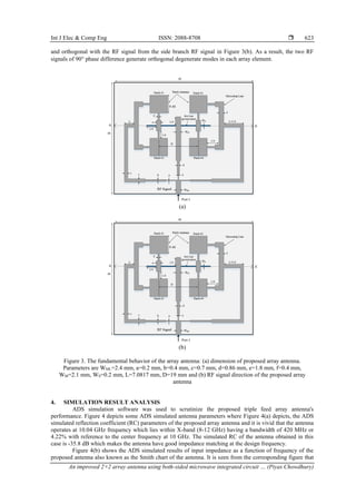
2.2. The triple feed network
In this proposed triple feed array antenna design, the input impedance of the microstrip line is to be
chosen as 50 Ω (2.4 mm). Figure 3 represents both the proposed antenna parameters and RF signals. From
Figure 3(a), it can be seen that the RF signal is divided into 3 feed lines with an equal thickness of ‘a’ where
each feed line has an impedance of 161 Ω. For proper matching between two feed lines at both left and right
sides of the four patch elements (shown as a thickness of ‘a’ and ‘c’ in the figure), 102 Ω (‘b’ thickness)
quarter wavelength transmission lines are used. The horizontal length of right-side feed line is a quarter
wavelength greater than that of the left-side feed line. In contrast, in the middle of four patches, a 92 Ω
(‘d’ thickness) quarter wavelength transmission line is used between two feed lines and the feed line ends
with microstrip-slot branch circuit. The slot line has an impedance of 108 Ω and a thickness of ‘WS’. The two
ends of this slot line create two slot-microstrip series branch circuits from where the two sides of microstrip
lines are fed to patch #1, patch #2, patch #3 and patch #4 through an impedance transformer of ‘e’ thickness
and maintain impedance of 62 Ω. By this proposed design, the feeding point of the RF signal is converted to
three feeding point and feed two RF signal of a different phase in each antenna element.
3. THE FUNDAMENTAL BEHAVIOUR OF THE ARRAY ANTENNA
The fundamental behavior of the proposed array antenna using a triple feed circuit has been
discussed in Figures 3(a) and 3(b) where the direction of RF signals is also given in different colors for the
clear realization of the antenna behavior. In this design, each patch element is fed by two different RF signals
which are orthogonal to each other resulting in circular polarization after creating two orthogonal degenerate
modes. RF signal is provided to microstrip line at Port1 of 50 Ω impedance. The RF signal is then divided
into three feed lines. From Figure 3(b), it is seen that two RF signals are fed to antenna array elements in the
same way and each of these RF signals is carried along three different microstrip lines to two array elements.
From the middle branch, the RF signal is initially divided into two ways through a parallel branch in phase
with microstrip line signals. Further, the RF signal then comes to two patch elements through another slot-
the microstrip branch. This incident happens on both sides of the slot line. But this RF signal is out of phase](https://image.slidesharecdn.com/v6227398emr26sep227feb22ff-221121065035-694b0dbc/85/An-improved-2x2-array-antenna-using-both-sided-microwave-integrated-circuit-technology-for-circular-polarization-4-320.jpg)
![ ISSN: 2088-8708
Int J Elec & Comp Eng, Vol. 13, No. 1, February 2023: 619-628
626
REFERENCES
[1] R. Garg, P. Bhartia, I. Bahl, and A. Ittipiboon, Microstrip antenna design handbook. 2001.
[2] M. A. Hossain, Y. Ushijima, E. Nishiyama, I. Toyoda, and M. Aikawa, “Orthogonal circular polarization detection patch array
antenna using double-balanced RF multiplier,” Progress in Electromagnetics Research C, vol. 30, pp. 65–80, 2012, doi:
10.2528/PIERC12032402.
[3] J.-S. Row, C. Y. D. Sim, and K.-W. Lin, “Broadband printed ring-slot array with circular polarisation,” Electronics Letters,
vol. 41, no. 3, 2005, doi: 10.1049/el:20057637.
[4] L. Sabri, N. Amiri, and K. Forooraghi, “SIW-fed microstrip patch antenna array for circular polarization,” International Journal
of Microwave and Wireless Technologies, vol. 9, no. 9, pp. 1877–1881, Nov. 2017, doi: 10.1017/S1759078717000617.
[5] K. Davies and E. K. Smith, “Ionospheric effects on satellite land mobile systems,” IEEE Antennas and Propagation Magazine,
vol. 44, no. 6, pp. 24–31, Dec. 2002, doi: 10.1109/MAP.2002.1167260.
[6] Q. Xue, X. Ren, and S. Liao, “Differentially-fed dual-polarized and shaped beam antennas for satellite communications,” in 13th
European Conference on Antennas and Propagation, 2019.
[7] A. H. Murshed, M. A. Hossain, M. A. Rahman, E. Nishiyama, and I. Toyoda, “Design and characterization of polarization
reconfigurable heart shape monopole antenna for 2.4 GHz application,” International Journal of Electrical and Computer
Engineering (IJECE), vol. 12, no. 4, pp. 3808–3819, Aug. 2022, doi: 10.11591/ijece.v12i4.pp3808-3819.
[8] J.-Y. Zhao, Z.-Y. Zhang, Y. Li, G. Fu, and S.-X. Gong, “Wideband patch antenna with stable high gain and low cross-polarization
characteristics,” Progress In Electromagnetics Research Letters, vol. 45, pp. 35–38, 2014, doi: 10.2528/PIERL14011404.
[9] H. Wong, K. K. So, K. B. Ng, K. M. Luk, C. H. Chan, and Q. Xue, “Virtually shorted patch antenna for circular polarization,”
IEEE Antennas and Wireless Propagation Letters, vol. 9, pp. 1213–1216, 2010, doi: 10.1109/LAWP.2010.2100361.
[10] K. Y. Lam, K.-M. Luk, K. F. Lee, H. Wong, and K. B. Ng, “Small circularly polarized U-slot wideband patch antenna,” IEEE
Antennas and Wireless Propagation Letters, vol. 10, pp. 87–90, 2011, doi: 10.1109/LAWP.2011.2110631.
[11] Y. Dong, H. Toyao, and T. Itoh, “Compact circularly-polarized patch antenna loaded with metamaterial structures,” IEEE
Transactions on Antennas and Propagation, vol. 59, no. 11, pp. 4329–4333, Nov. 2011, doi: 10.1109/TAP.2011.2164223.
[12] K.-Lu Wong and T.-W. Chiou, “Broad-band single-patch circularly polarized microstrip antenna with dual capacitively coupled
feeds,” IEEE Transactions on Antennas and Propagation, vol. 49, no. 1, pp. 41–44, 2001, doi: 10.1109/8.910527.
[13] M. A. Rahman, E. Nishiyama, and I. Toyoda, “Quadrature hybrid integrated dual-circularly polarized array antenna,” in
Proceedings of the 2018 IEEE 7th
Asia-Pacific Conference on Antennas and Propagation, Aug. 2018, pp. 145–146, doi:
10.1109/APCAP.2018.8538245.
[14] Y. Ushijima, S. Feng, E. Nishiyama, and M. Aikawa, “A novel circular polarization switchable slot-ring array antenna with
orthogonal feed circuit,” in Asia-Pacific Microwave Conference Proceedings, 2010, pp. 1569–1572.
[15] M. A. Rahman, E. Nishiyama, M. A. Hossain, Q. D. Hossain, and I. Toyoda, “A multi-layer approach of orthogonally fed
circularly polarized microstrip array antenna for enhanced gain,” International Journal of Microwave and Wireless Technologies,
vol. 11, no. 5–6, pp. 532–542, Jun. 2019, doi: 10.1017/S1759078719000151.
[16] A. H. Murshed, M. A. Hossain, E. Nishiyama, and I. Toyoda, “Design and characterization of frequency reconfigurable honey bee
antenna for cognitive radio application,” International Journal of Electrical and Computer Engineering (IJECE), vol. 12, no. 6,
pp. 6178–6186, Dec. 2022, doi: 10.11591/ijece.v12i6.pp6178-6186.
[17] W. Lin and H. Wong, “Wideband circular polarization reconfigurable antenna,” IEEE Transactions on Antennas and
Propagation, vol. 63, no. 12, pp. 5938–5944, Dec. 2015, doi: 10.1109/TAP.2015.2489210.
[18] J.-S. Row and C.-W. Tsai, “Pattern reconfigurable antenna array with circular polarization,” IEEE Transactions on Antennas and
Propagation, vol. 64, no. 4, pp. 1525–1530, Apr. 2016, doi: 10.1109/TAP.2016.2522467.
[19] W. Li et al., “Polarization-reconfigurable circularly polarized planar antenna using switchable polarizer,” IEEE Transactions on
Antennas and Propagation, vol. 65, no. 9, pp. 4470–4477, Sep. 2017, doi: 10.1109/TAP.2017.2730240.
[20] D. Im, B.-K. Kim, D.-K. Im, and K. Lee, “A stacked-FET linear SOI CMOS cellular antenna switch with an extremely low-power
biasing strategy,” IEEE Transactions on Microwave Theory and Techniques, vol. 63, no. 6, pp. 1964–1977, Jun. 2015, doi:
10.1109/TMTT.2015.2427801.
[21] B. Anantha, L. Merugu, and S. Rao P.V.D, “Polarization reconfigurable corner truncated square microstrip array antenna,” IETE
Journal of Research, vol. 67, no. 4, pp. 491–498, Jul. 2021, doi: 10.1080/03772063.2018.1557084.
[22] J.-S. Row and T.-Y. Lin, “Frequency-reconfigurable coplanar patch antenna with conical radiation,” IEEE Antennas and Wireless
Propagation Letters, vol. 9, pp. 1088–1091, 2010, doi: 10.1109/LAWP.2010.2093118.
[23] H. Boudaghi, M. Azarmanesh, and M. Mehranpour, “A frequency-reconfigurable monopole antenna using switchable slotted
ground structure,” IEEE Antennas and Wireless Propagation Letters, vol. 11, pp. 655–658, 2012, doi:
10.1109/LAWP.2012.2204030.
[24] G. Chen, X.-L. Yang, and Y. Wang, “Dual-band frequency-reconfigurable folded slot antenna for wireless communications,”
IEEE Antennas and Wireless Propagation Letters, vol. 11, pp. 1386–1389, 2012, doi: 10.1109/LAWP.2012.2227293.
[25] A. Khidre, F. Yang, and A. Z. Elsherbeni, “A patch antenna with a varactor-loaded slot for reconfigurable dual-band operation,”
IEEE Transactions on Antennas and Propagation, vol. 63, no. 2, pp. 755–760, 2015, doi: 10.1109/TAP.2014.2376524.
[26] J. Xu, W. Hong, Z. H. Jiang, J. Chen, and H. Zhang, “A Q-band low-profile dual circularly polarized array antenna incorporating
linearly polarized substrate integrated waveguide-fed patch subarrays,” IEEE Transactions on Antennas and Propagation, vol. 65,
no. 10, pp. 5200–5210, Oct. 2017, doi: 10.1109/TAP.2017.2741065.
[27] S. Li, S. Liao, Y. Yang, W. Che, and Q. Xue, “A low-profile sequential rotation-fed circularly polarized annular aperture antenna
array for earth coverage applications,” in IEEE MTT-S International Wireless Symposium (IWS), Sep. 2020, pp. 1–3, doi:
10.1109/IWS49314.2020.9360110.
[28] R. Sen Goopta, Q. Delwar Hossain, M. A. Hossain, and P. Chowdhury, “Design of a circular polarization array antenna using
triple feed structure,” in 9th
International Forum on Strategic Technology (IFOST), Oct. 2014, pp. 191–194, doi:
10.1109/IFOST.2014.6991102.
[29] M. A. Hossain, A. H. Murshed, M. A. Rahman, E. Nishiyama, and I. Toyoda, “A gain enhanced linear polarization switchable
array antenna with switching diodes,” International Journal of RF and Microwave Computer-Aided Engineering, vol. 32, no. 10,
Oct. 2022, doi: 10.1002/mmce.23291.
[30] M. A. Rahman, Q. D. Hossain, M. A. Hossain, E. Nishiyama, and I. Toyoda, “Design and parametric analysis of a planar array
antenna for circular polarization,” International Journal of Microwave and Wireless Technologies, vol. 8, no. 6, pp. 921–929,
Sep. 2016, doi: 10.1017/S1759078715000264.
[31] A. H. Murshed, M. A. Hossain, M. A. Rahman, E. Nishiyama, and I. Toyoda, “Designing of a both-sided MIC starfish microstrip](https://image.slidesharecdn.com/v6227398emr26sep227feb22ff-221121065035-694b0dbc/85/An-improved-2x2-array-antenna-using-both-sided-microwave-integrated-circuit-technology-for-circular-polarization-8-320.jpg)
![Int J Elec & Comp Eng ISSN: 2088-8708
An improved 2×2 array antenna using both-sided microwave integrated circuit … (Piyas Chowdhury)
627
array antenna for K-Band application,” in IEEE Region 10 Symposium (TENSYMP), Aug. 2021, pp. 1–6, doi:
10.1109/TENSYMP52854.2021.9550909.
[32] T. Seki, K. Nishikawa, I. Toyoda, and S. Kubota, “Microstrip array antenna with parasitic elements alternately arranged over two
layers of LTCC substrate for millimeter wave applications,” in 2007 IEEE Radio and Wireless Symposium, 2007, pp. 149–152,
doi: 10.1109/RWS.2007.351789.
[33] F. Xu, K. Wu, and X. Zhang, “Periodic leaky-wave antenna for millimeter wave applications based on substrate integrated
waveguide,” IEEE Transactions on Antennas and Propagation, vol. 58, no. 2, pp. 340–347, Feb. 2010, doi:
10.1109/TAP.2009.2026593.
[34] W. Hong, N. Behdad, and K. Sarabandi, “Size reduction of cavity-backed slot antennas,” IEEE Transactions on Antennas and
Propagation, vol. 54, no. 5, pp. 1461–1466, May 2006, doi: 10.1109/TAP.2006.874351.
[35] T. Zhang, W. Hong, Y. Zhang, and K. Wu, “Design and analysis of SIW cavity backed dual-band antennas with a dual-mode
triangular-ring slot,” IEEE Transactions on Antennas and Propagation, vol. 62, no. 10, pp. 5007–5016, Oct. 2014, doi:
10.1109/TAP.2014.2345581.
[36] S. Mukherjee, A. Biswas, and K. V. Srivastava, “Substrate integrated waveguide cavity-backed dumbbell-shaped slot antenna for
dual-frequency applications,” IEEE Antennas and Wireless Propagation Letters, vol. 14, pp. 1314–1317, 2015, doi:
10.1109/LAWP.2014.2384018.
[37] T. Liang, Z. Wang, and Y. Dong, “A circularly polarized SIW slot antenna based on high-order dual-mode cavity,” IEEE
Antennas and Wireless Propagation Letters, vol. 19, no. 3, pp. 388–392, Mar. 2020, doi: 10.1109/LAWP.2020.2972115.
[38] C. A. T. Martinez, J. C. B. Reyes, O. A. N. Manosalva, and N. M. P. Traslavina, “Volume reduction of planar substrate integrated
waveguide cavity-backed antennas,” in 6th European Conference on Antennas and Propagation (EUCAP), Mar. 2012,
pp. 2919–2923, doi: 10.1109/EuCAP.2012.6206037.
[39] S. A. Razavi and M. H. Neshati, “Development of a linearly polarized cavity-backed antenna using HMSIW technique,” IEEE
Antennas and Wireless Propagation Letters, vol. 11, pp. 1307–1310, 2012, doi: 10.1109/LAWP.2012.2227231.
[40] J. Xu, W. Hong, H. Tang, Z. Kuai, and K. Wu, “Half-mode substrate integrated waveguide (HMSIW) leaky-wave antenna for
millimeter-wave applications,” IEEE Antennas and Wireless Propagation Letters, vol. 7, pp. 85–88, 2008, doi:
10.1109/LAWP.2008.919353.
BIOGRAPHIES OF AUTHORS
Piyas Chowdhury received B.Sc degree in Engineering from Electrical and
Electronic Engineering (EEE) from Chittagong University of Engineering and Technology
(CUET) in 2011. He is currently working as assistant professor at the department of
Electronics and Telecommunication Engineering (ETE). His research interests include
microstrip antenna, power system, control system, and machine learning. He can be contacted
at email: piyas@cuet.ac.bd.
Nishako Chakma received B.Sc in Engineering degree in Electronics and
Telecommunication Engineering (ETE) from Chittagong University of Engineering and
Technology, Chittagong, Bangladesh in June 2017. She is currently working toward the Ph.D.
degree in electrical engineering at the University of North Texas. Her research interests
include antenna designs for microwave ablation. She can be contacted at email:
nishako.ete@gmail.com.
Abu Hena Murshed was born in Feni, Bangladesh, in 1998. He received his B.Sc
degree in Electronics and Telecommunication Engineering (ETE) from Chittagong University
of Engineering and Technology (CUET) in June 2021, Chittagong, in Bangladesh. He is
currently working towards about Microstrip Antenna and circuit Design. He is working as
research assistant at CUET. His research field of interests are metamaterial antenna, electro-
bandgap (EBG) antenna, 5G antenna and its related experimental characterization. He can be
contacted at email: u1508017@student.cuet.ac.bd.](https://image.slidesharecdn.com/v6227398emr26sep227feb22ff-221121065035-694b0dbc/85/An-improved-2x2-array-antenna-using-both-sided-microwave-integrated-circuit-technology-for-circular-polarization-9-320.jpg)