Download as PDF, PPTX


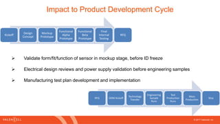
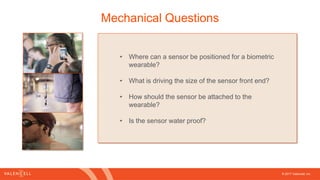
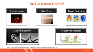
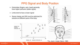


This document discusses challenges in integrating biometric sensors into wearable devices from engineering perspectives. It addresses questions product managers, mechanical engineers, and software engineers may have around sensor placement, form factor considerations, electrical design, software integration, testing, and validation. The document provides recommendations on sensor size and positioning, attachment methods, interface choices, power supplies, metrics, algorithms, and production testing protocols to optimize sensor performance for different use cases.


