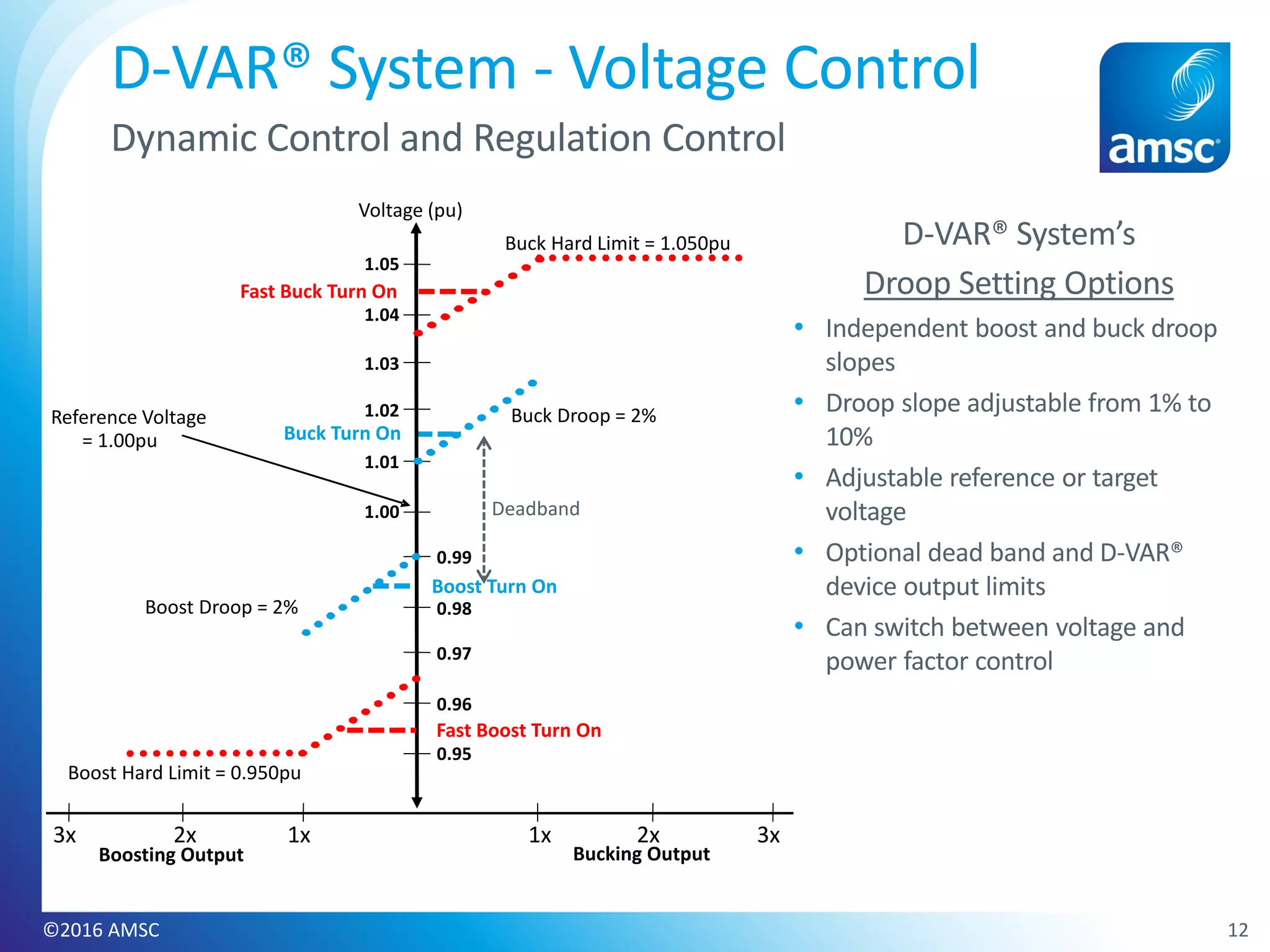
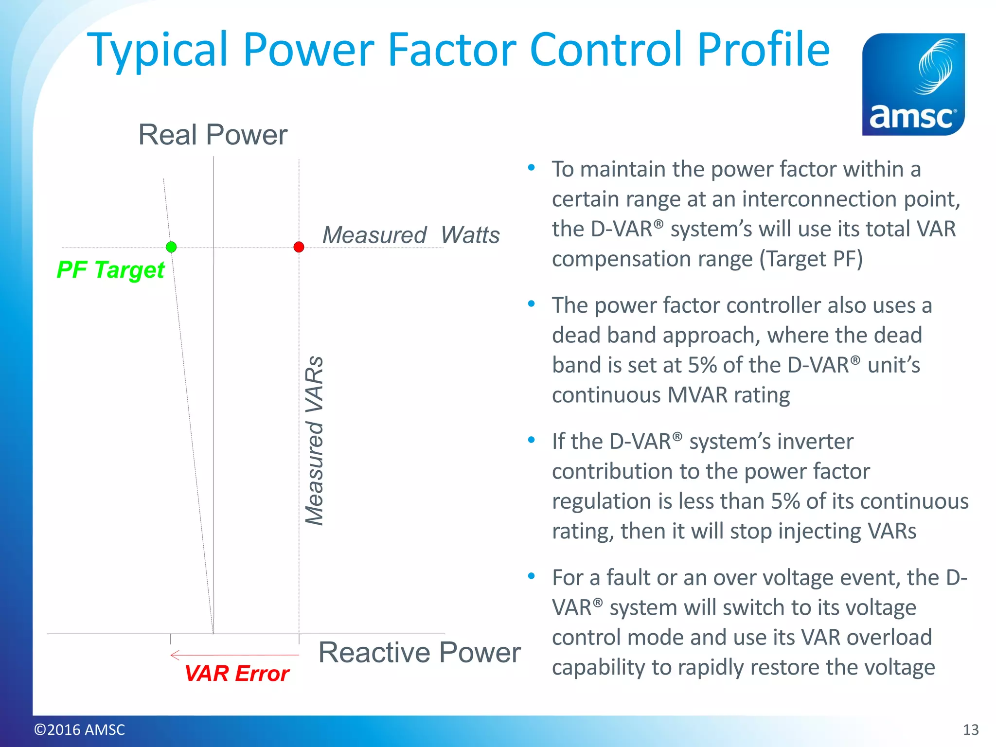
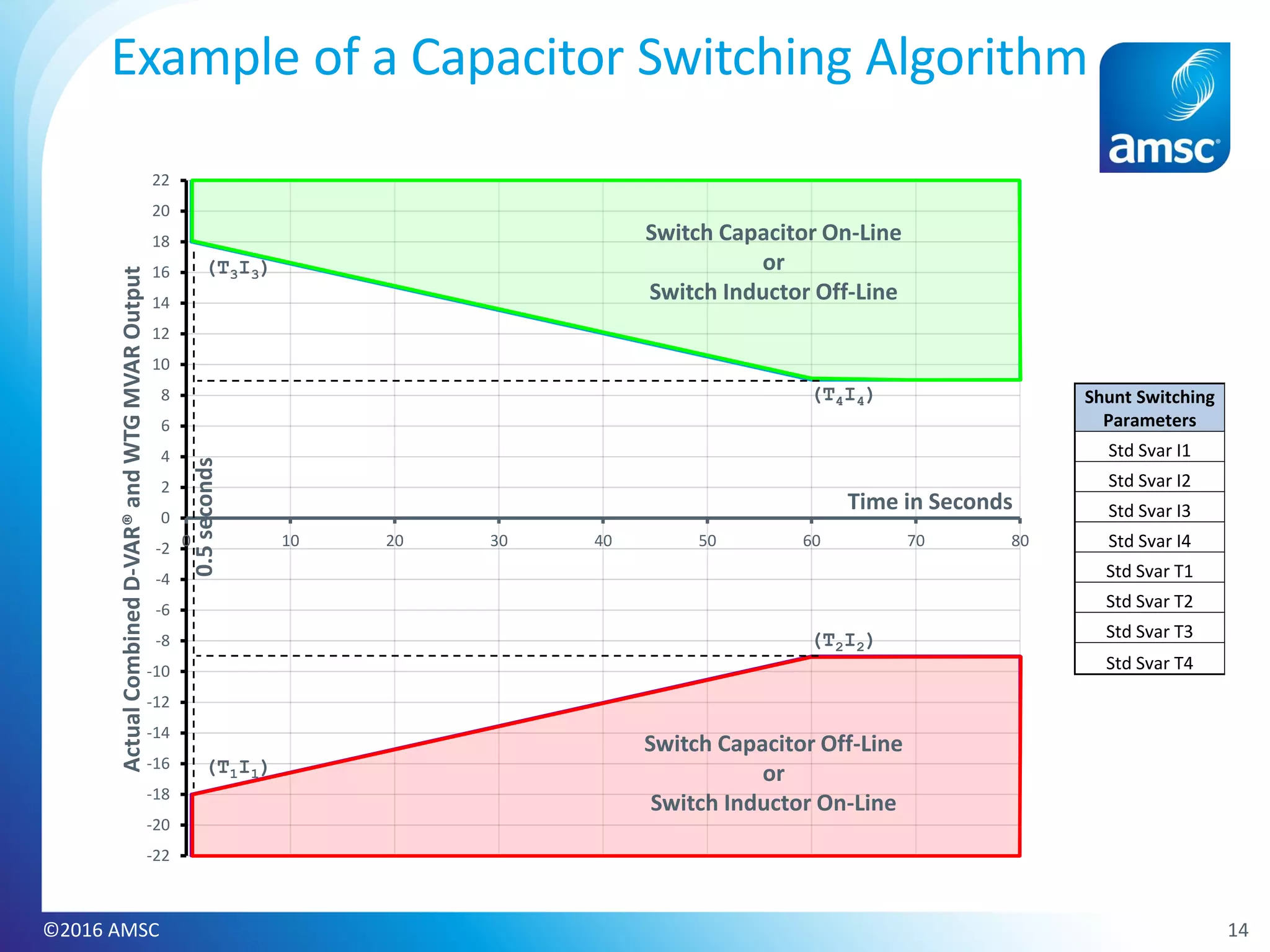
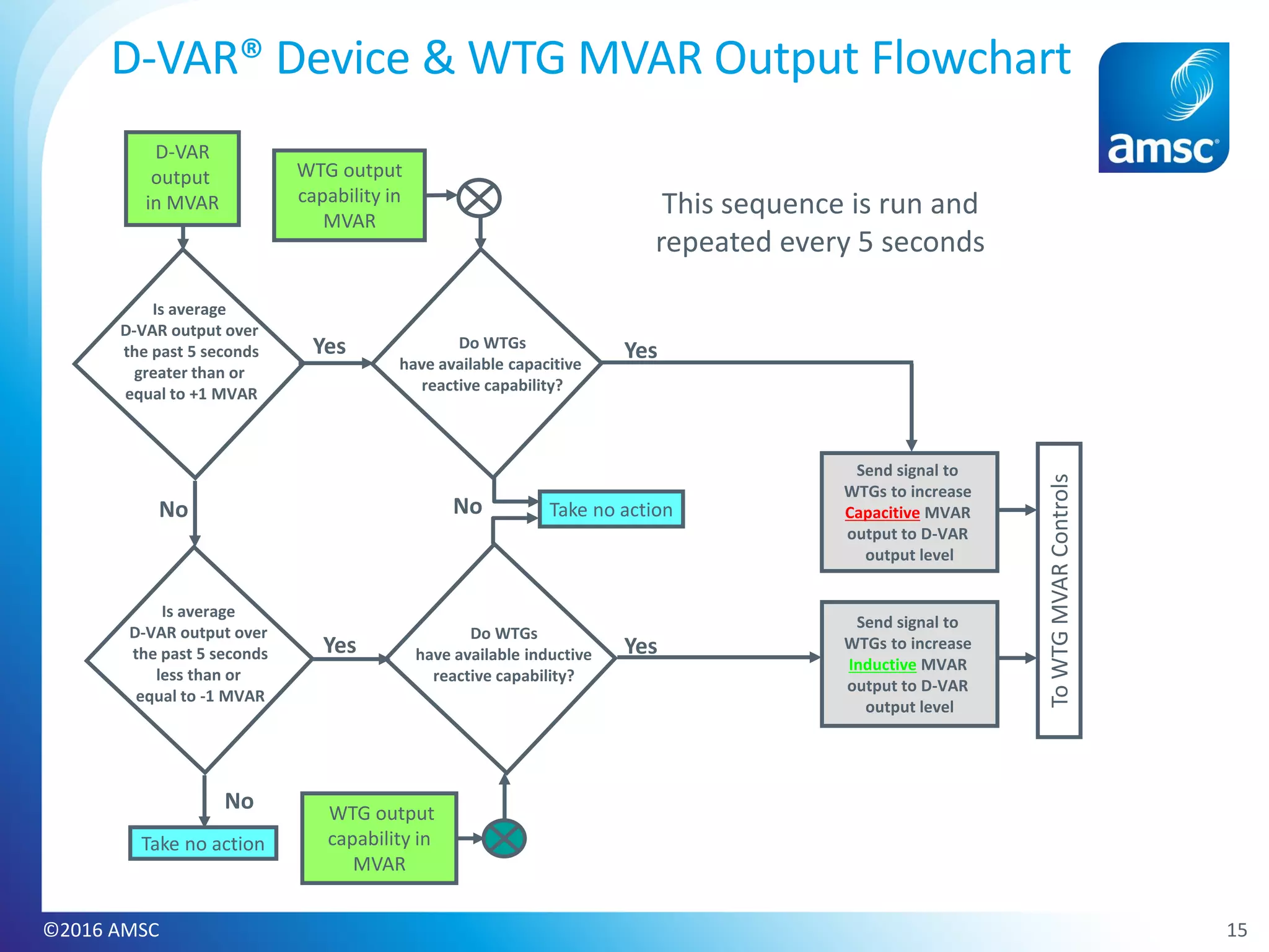
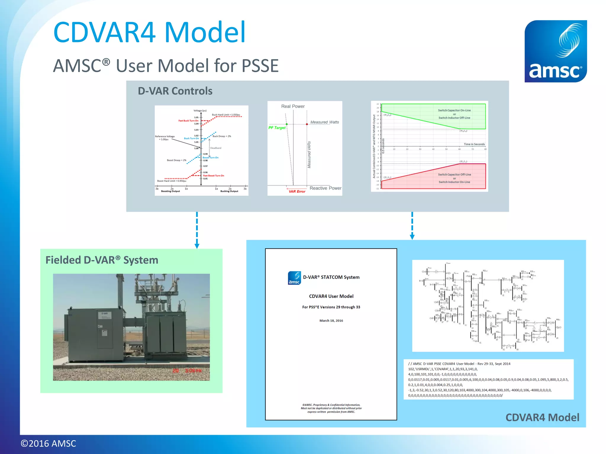
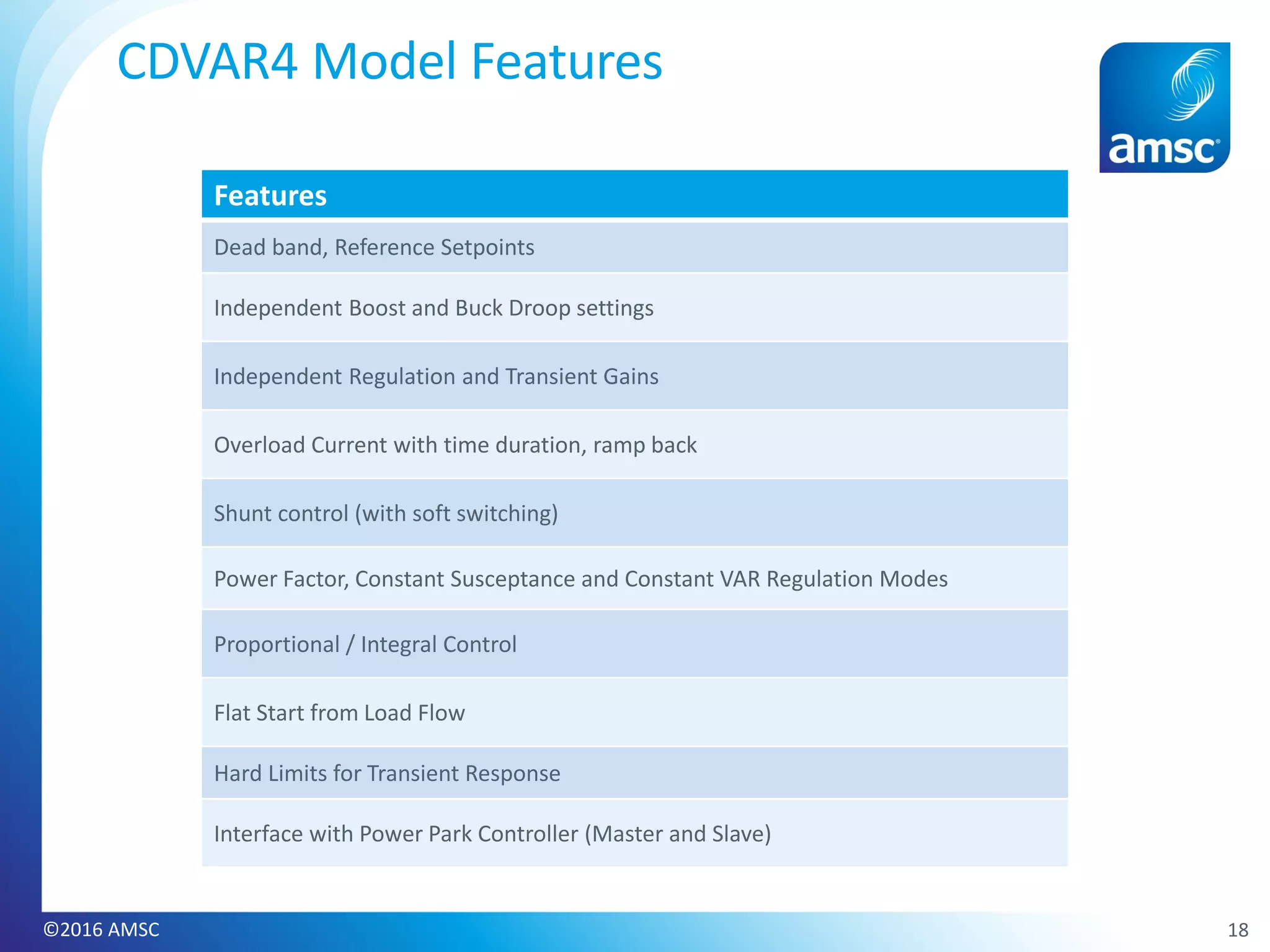
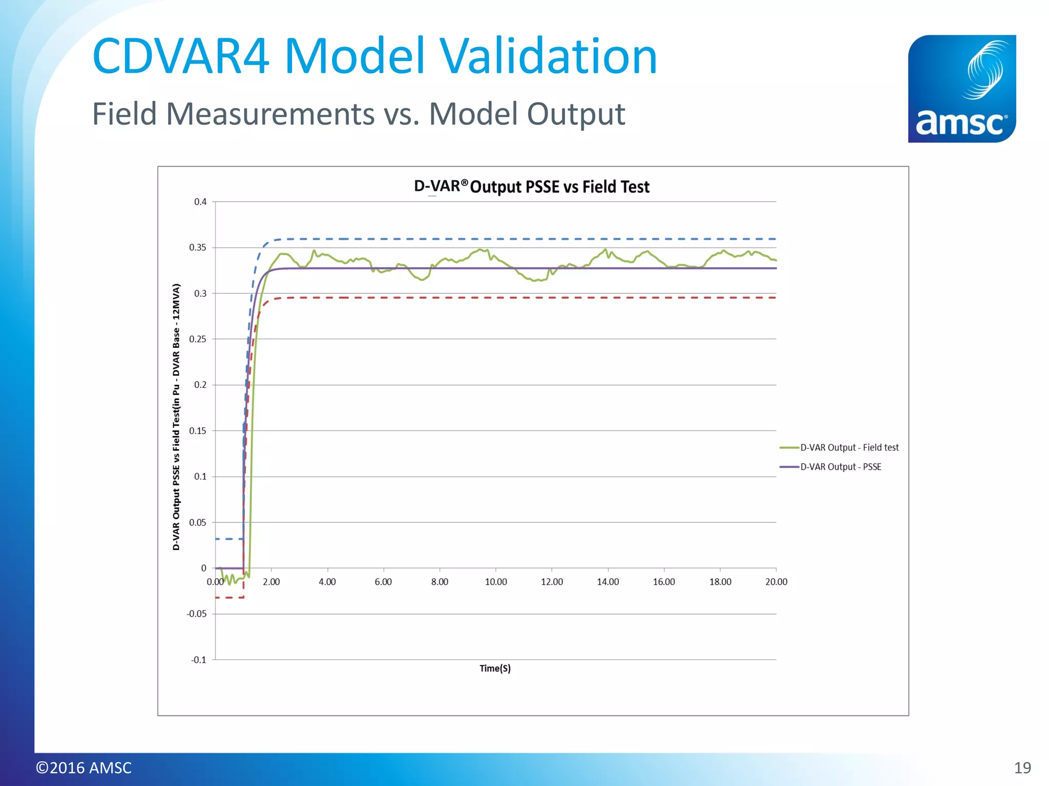
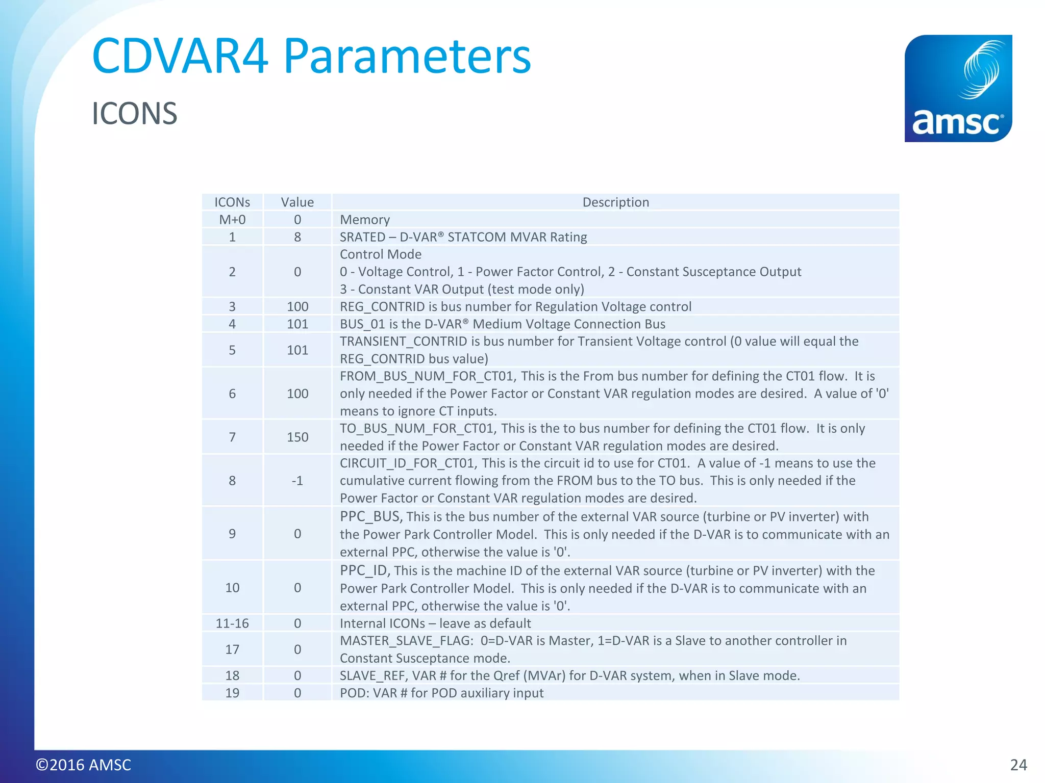
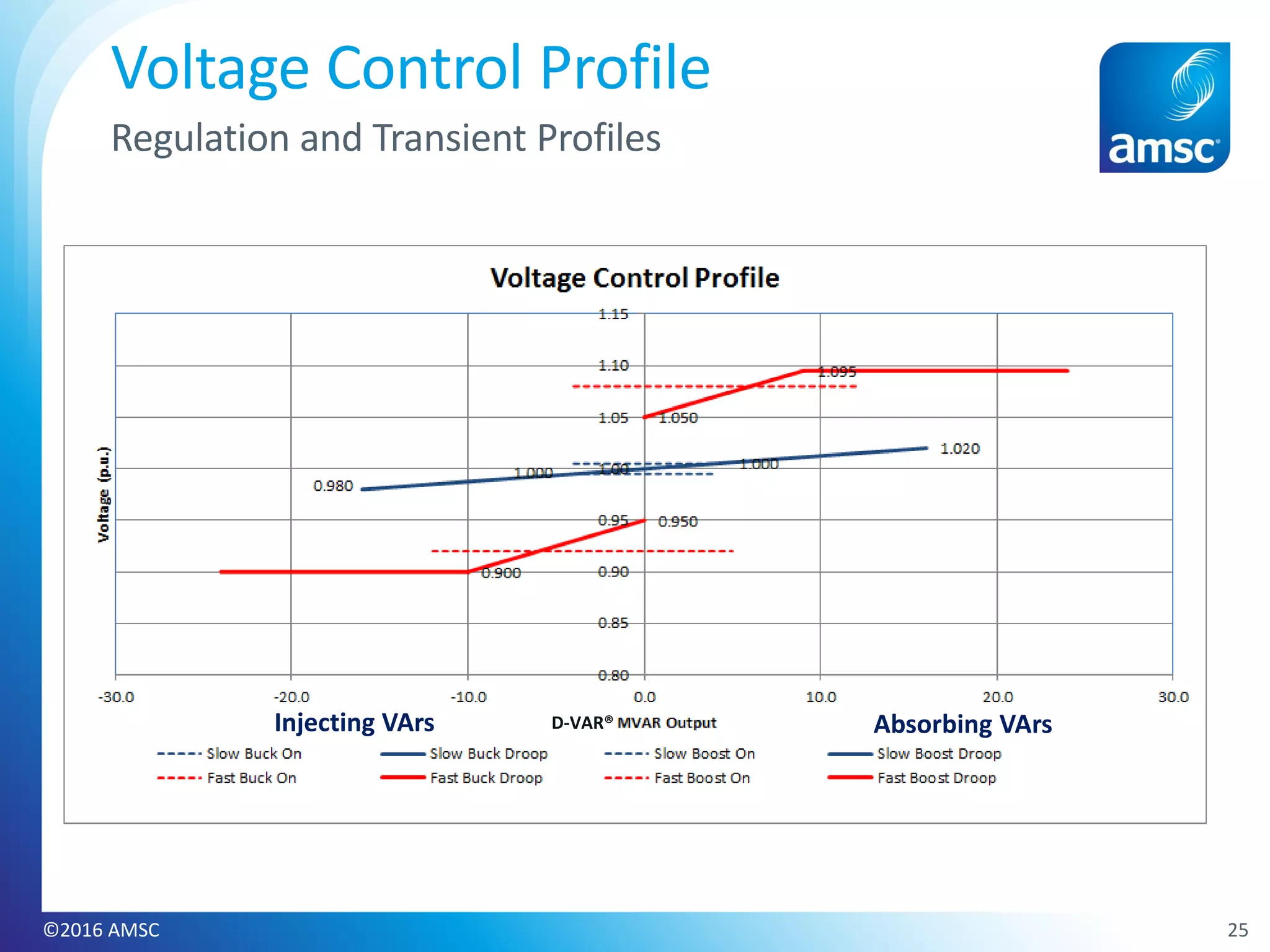
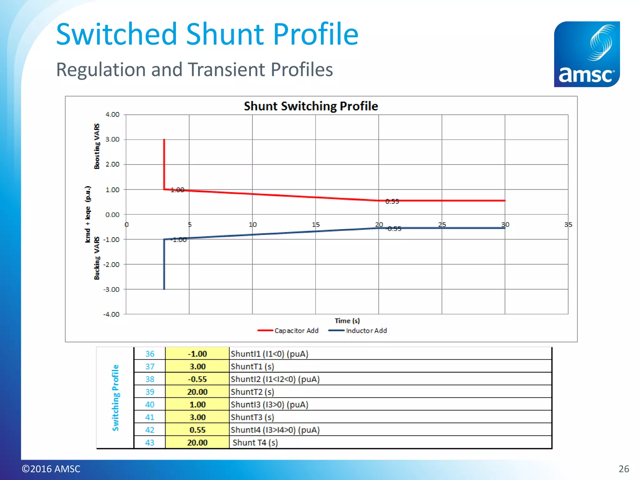
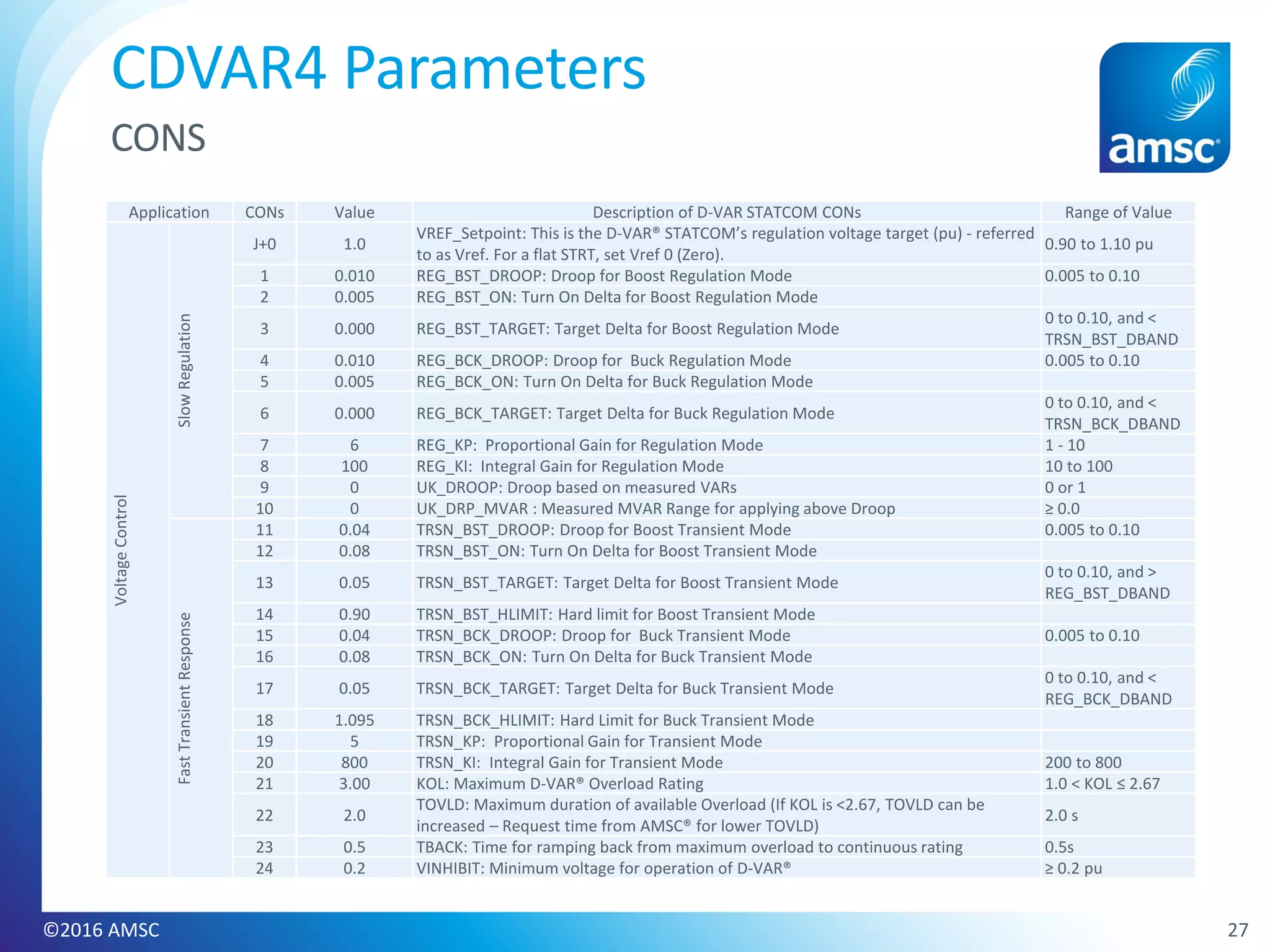
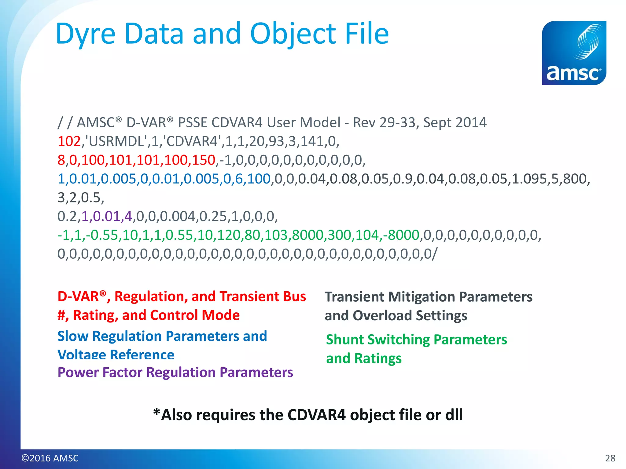
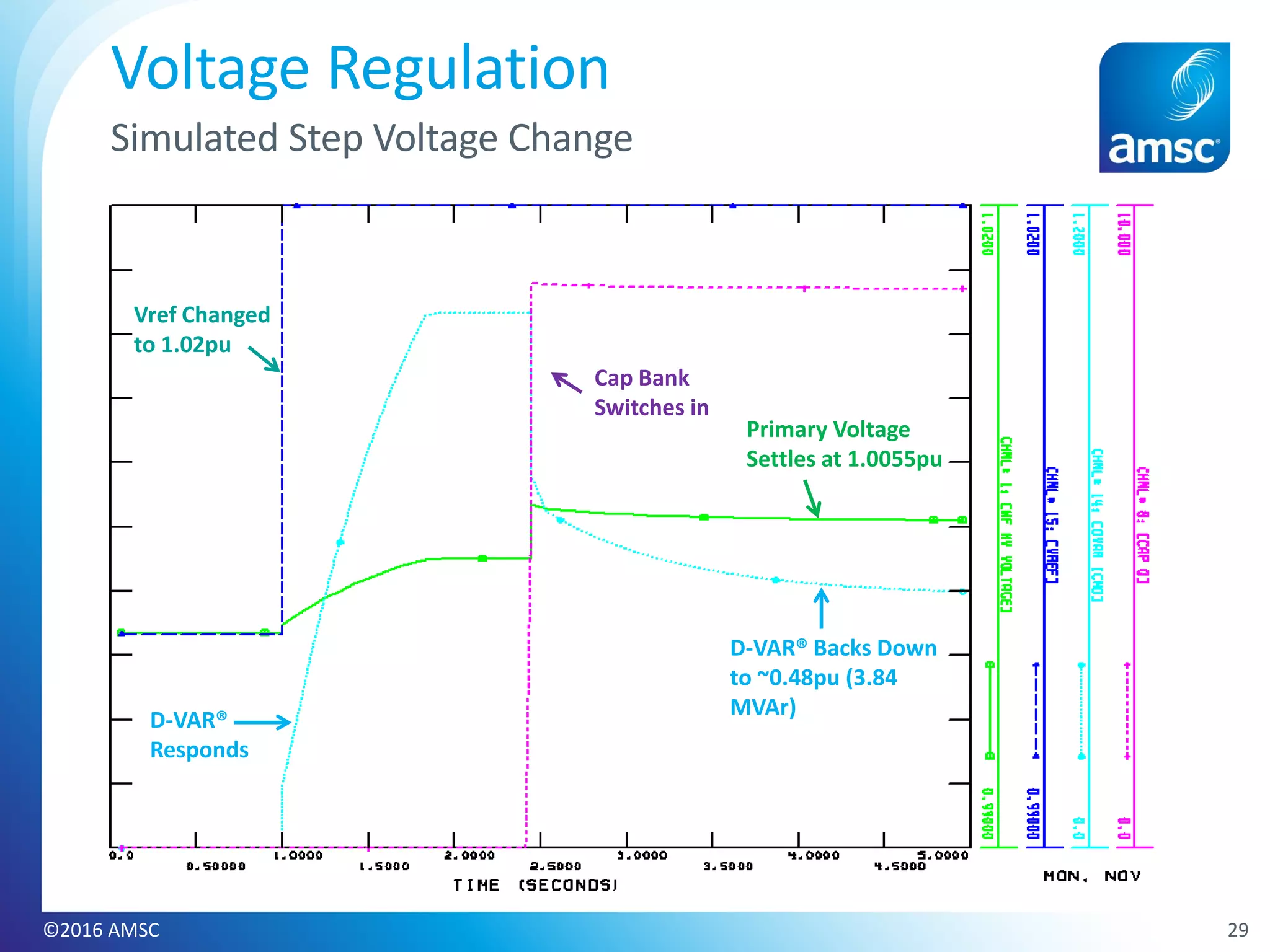
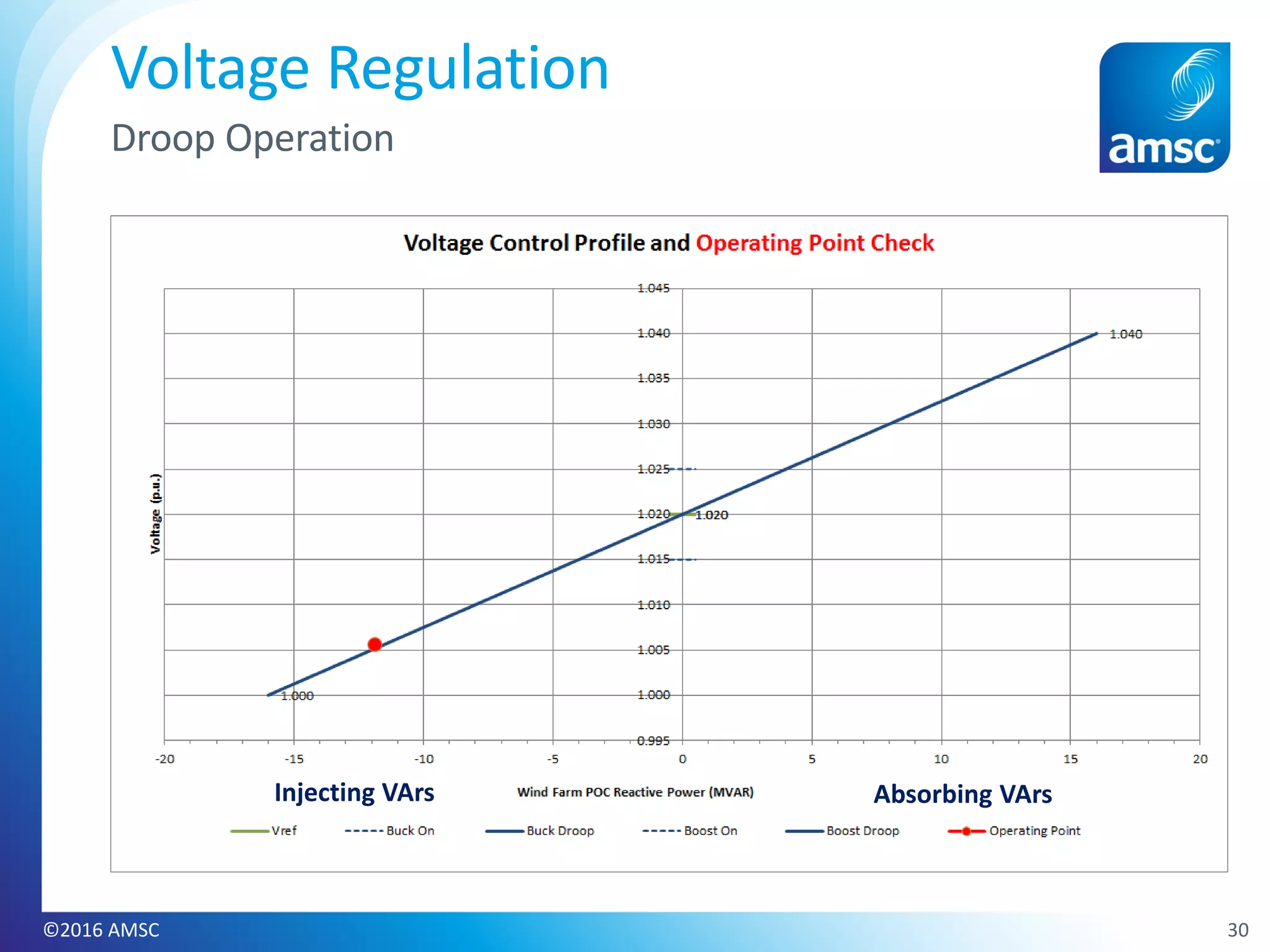
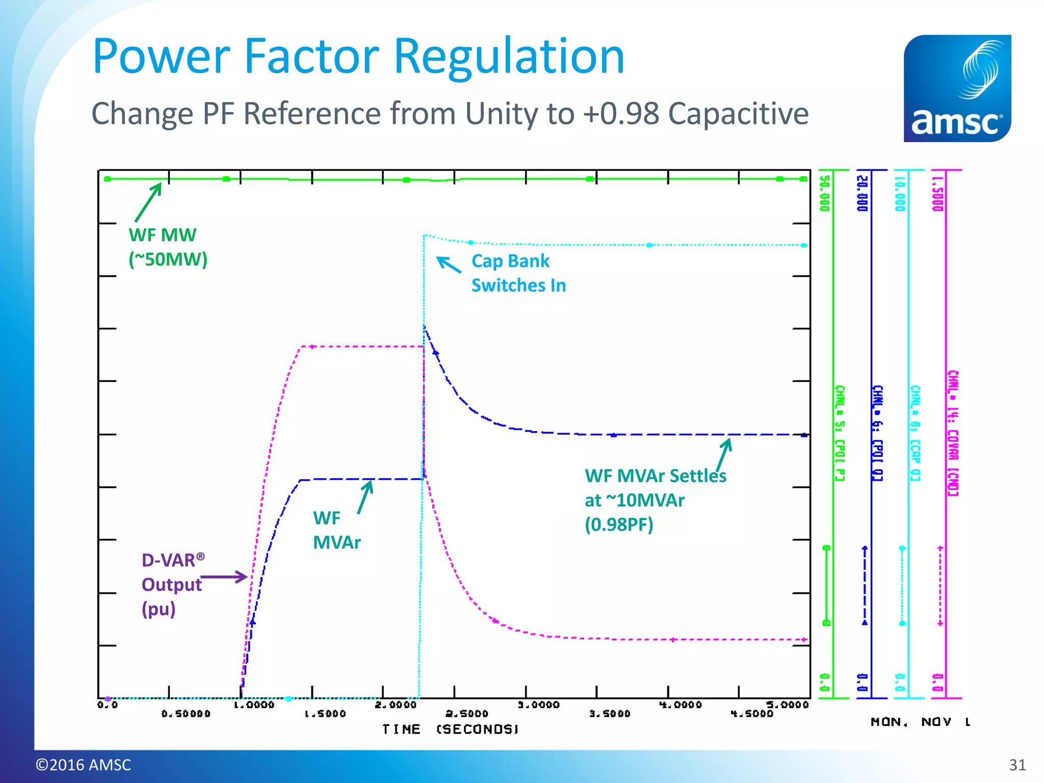
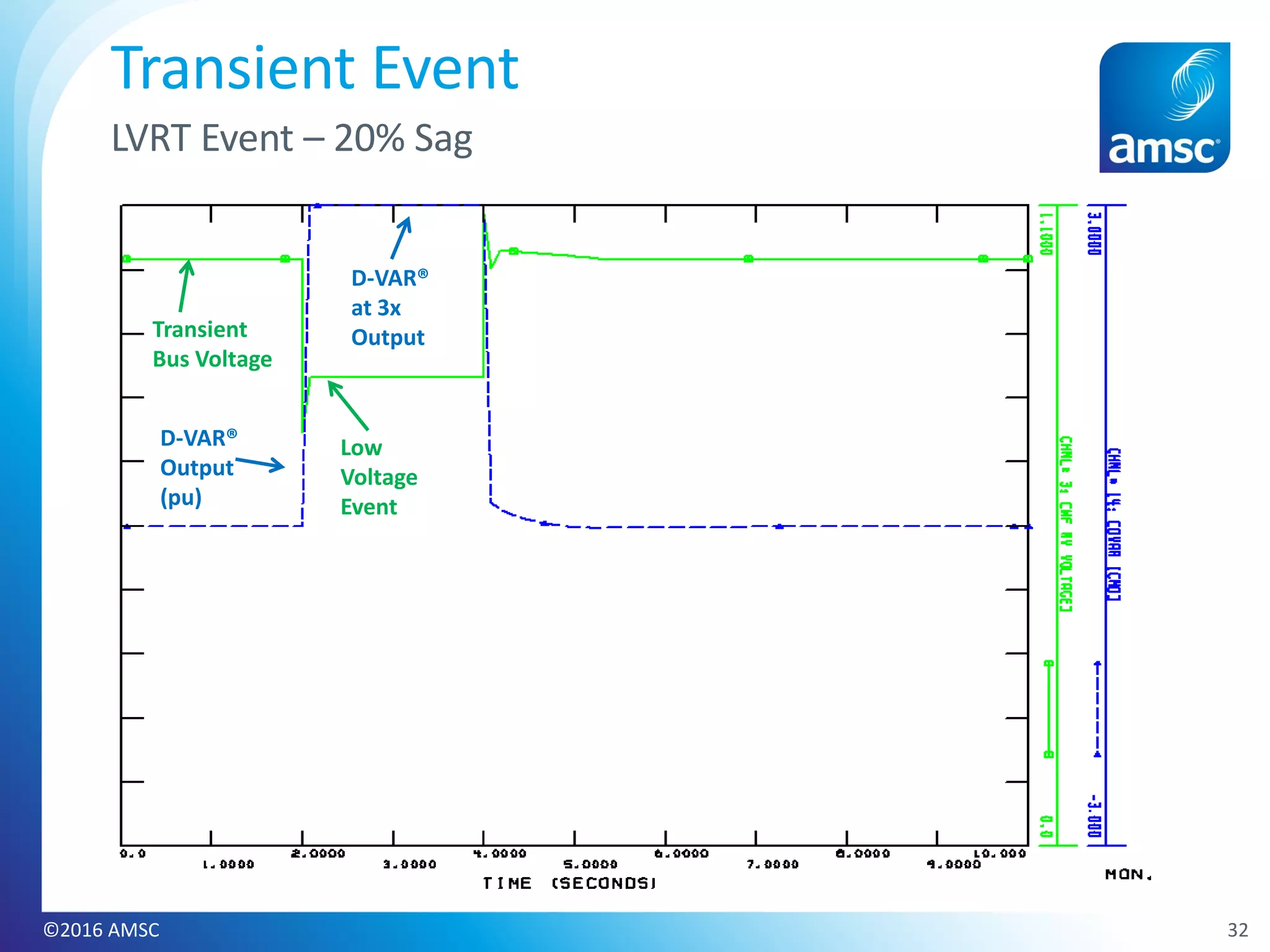
More Related Content
Similar to AMSC D-VAR® Model for PSSE_releasable
Similar to AMSC D-VAR® Model for PSSE_releasable (20)
AMSC D-VAR® Model for PSSE_releasable
- 1. AMSC® D-VAR® Model for PSSE
Introduction to CDVAR4 User Model
PSSE Users Group Meeting - Sydney, Australia
November 2016
©2016 AMSC
- 2. • AMSC® (American Superconductor) is a leading global manufacturer of
solutions for electric grids.
• AMSC® solutions are powering 14 GW of renewable energy and enhancing
the performance and reliability in power networks in more than a dozen
countries.
• Founded in 1987 as a start-up – company founder from the Massachusetts
Institute of Technology (MIT)
• Headquartered near Boston, Massachusetts with operations in Asia,
Australia, Europe and North America.
AMSC®
Introduction
©2016 AMSC 2
- 5. AMSC® D-VAR® STATCOM Applications
Renewables
• Delivery of more power on
existing transmission &
distribution assets
• Postpone investments
• Improvement of power
stability, availability, quality
and reliability
• 21 Systems Installed
• Largest System Size:
-96/+240 MVAR
• Enables renewable power
to “act like” power from a
conventional source so it
can be smoothly
integrated into the power
grid in compliance with
local grid codes
• 92 Systems Installed
• Largest System Size:
+308/-256MVAR
• Eliminate voltage
disturbances to ensure
high power quality for
semiconductor fabs,
mining operations and
other industrial processes.
• 7 Systems Installed
• Largest System Size:
+/-168 MVAR
RenewablesUtilities Industrials
©2016 AMSC 5
- 7. 7
World Wide Grid Code Requirements
To alleviate the growing impacts of renewables on the grid
Grid code requirements vary from region to region.
Reference: AESO ISO Rules Part 500 - Facilities
Division 502 – Technical Requirements Section
502.1 – Wind Aggregated Generating Facilities
Technical Requirements August 10, 2010
Reference: UK Grid Code,
December 13, 2013
Reference: Romania - Technical conditions for connection to the
public electrical grids for electrical
wind power stations, March 4, 2009
Reference: ESCOSA Electricity
Transmission Code, July 1, 2008
Reference: ESKOM Grid Connection Code for RPPs in South Africa -
Version 2.8, July 2014
©2016 AMSC
- 8. • The Grid Code Requirements are
imposed at the Point of
Interconnection of the Wind Farm
to the Transmission Grid
• Variety of reactive resources are
required to fully meet the grid
code requirements
– Often the assistance of STATCOMs
are required
– Creative control systems have been
implemented to integrate all
reactive resources to meet the
various grid codes
8
World Wide Grid Code Requirements
Requirements Met Using a Variety of Reactive Resources
Creative controls allow multiple reactive resources to assist in
meeting the various grid code requirements.
Shunt Banks
4 MVAR
D-VAR ®
Wind Turbine Generators
With Reactive Capability
Utility Grid
CT
PT
MCE - Master Control Enclosure
PT
Breaker
Switch
Medium Voltage
Point of Interconnection
Transmission Voltage
Reactive Power
Commands
Voltage/Current Monitoring
MVAR
Control
MCE
©2016 AMSC
- 9. • AMSC® Support Capability for Systems Engineering
– Steady-state load flow (power flow) studies
– Dynamic and stability analysis
– Harmonics and resonance scans
– Power transfer capability studies
• Planning Tools (Software)
– PTI PSS/E Load flow and Stability
– DIgSILENT load flow, stability, harmonics, short circuit
– PSCAD and RTDS
– GE PSLF Load flow and Stability
• Global Experience
– Studies performed for wind farms, industrial plants and utilities
worldwide
AMSC® Planning & Engineering Services
9©2016 AMSC
- 11. • Voltage Control (Regulation/Transient)
̶ Line Drop Compensation
• Power Factor Control
• Constant MVAR Control
• Capacitor/Reactor Bank Switching Control
• Wind Farm/Solar Plant MVAR Output Control
11
D-VAR® System Control Options
Available
©2016 AMSC
- 12. D-VAR® System’s
Droop Setting Options
• Independent boost and buck droop
slopes
• Droop slope adjustable from 1% to
10%
• Adjustable reference or target
voltage
• Optional dead band and D-VAR®
device output limits
• Can switch between voltage and
power factor control
12
D-VAR® System - Voltage Control
Dynamic Control and Regulation Control
Boosting Output Bucking Output
1.00
1.01
1.02
1.03
1.04
0.96
0.97
0.98
0.99
Reference Voltage
= 1.00pu
Voltage (pu)
1x2x3x 1x 2x 3x
Deadband
Buck Droop = 2%
Boost Droop = 2%
Buck Hard Limit = 1.050pu
Boost Hard Limit = 0.950pu
1.05
0.95
Fast Buck Turn On
Fast Boost Turn On
Buck Turn On
Boost Turn On
©2016 AMSC
- 13. • To maintain the power factor within a
certain range at an interconnection point,
the D-VAR® system’s will use its total VAR
compensation range (Target PF)
• The power factor controller also uses a
dead band approach, where the dead
band is set at 5% of the D-VAR® unit’s
continuous MVAR rating
• If the D-VAR® system’s inverter
contribution to the power factor
regulation is less than 5% of its continuous
rating, then it will stop injecting VARs
• For a fault or an over voltage event, the D-
VAR® system will switch to its voltage
control mode and use its VAR overload
capability to rapidly restore the voltage
13
Typical Power Factor Control Profile
Reactive Power
Real Power
MeasuredVARs
Measured Watts
PF Target
VAR Error
©2016 AMSC
- 14. 14
Example of a Capacitor Switching Algorithm
-22
-20
-18
-16
-14
-12
-10
-8
-6
-4
-2
0
2
4
6
8
10
12
14
16
18
20
22
0 10 20 30 40 50 60 70 80
Time in Seconds
ActualCombinedD-VAR®andWTGMVAROutput
0.5seconds
(T3I3)
(T4I4)
(T1I1)
(T2I2)
Switch Capacitor Off-Line
or
Switch Inductor On-Line
Switch Capacitor On-Line
or
Switch Inductor Off-Line
Shunt Switching
Parameters
Std Svar I1
Std Svar I2
Std Svar I3
Std Svar I4
Std Svar T1
Std Svar T2
Std Svar T3
Std Svar T4
©2016 AMSC
- 15. 15
D-VAR® Device & WTG MVAR Output Flowchart
Yes
Is average
D-VAR output over
the past 5 seconds
greater than or
equal to +1 MVAR
D-VAR
output
in MVAR
No
Take no action
Do WTGs
have available capacitive
reactive capability?
Yes
Yes
No
No
Is average
D-VAR output over
the past 5 seconds
less than or
equal to -1 MVAR
Send signal to
WTGs to increase
Capacitive MVAR
output to D-VAR
output level
WTG output
capability in
MVAR
Take no action
Do WTGs
have available inductive
reactive capability?
Yes
Send signal to
WTGs to increase
Inductive MVAR
output to D-VAR
output level
ToWTGMVARControls
This sequence is run and
repeated every 5 seconds
WTG output
capability in
MVAR
©2016 AMSC
- 18. CDVAR4 Model Features
Features
Dead band, Reference Setpoints
Independent Boost and Buck Droop settings
Independent Regulation and Transient Gains
Overload Current with time duration, ramp back
Shunt control (with soft switching)
Power Factor, Constant Susceptance and Constant VAR Regulation Modes
Proportional / Integral Control
Flat Start from Load Flow
Hard Limits for Transient Response
Interface with Power Park Controller (Master and Slave)
18©2016 AMSC
- 20. • Load Flow set up
• Parameters – DYRE data set up
• Object File
• Demonstration of Model Performance
20©2016 AMSC
CDVAR4 Model Overview
- 21. 21©2016 AMSC
CDVAR4 Load Flow Set Up
8 MVAr D-VAR® 8 MVAr Capacitor
8 MVAr Reactor
Primary
Regulation Bus
Transient
Regulation Bus
- 23. 23©2016 AMSC
CDVAR4 Parameters
Model Definition
Value Description
102 D-VAR® Bus Number
1 Machine ID (number or up to two letters)
CDVAR4 D-VAR® User Model Name
20 ICONs
93 CONs
3 STATEs
141 VARs
- 24. 24©2016 AMSC
CDVAR4 Parameters
ICONS
ICONs Value Description
M+0 0 Memory
1 8 SRATED – D-VAR® STATCOM MVAR Rating
2 0
Control Mode
0 - Voltage Control, 1 - Power Factor Control, 2 - Constant Susceptance Output
3 - Constant VAR Output (test mode only)
3 100 REG_CONTRID is bus number for Regulation Voltage control
4 101 BUS_01 is the D-VAR® Medium Voltage Connection Bus
5 101
TRANSIENT_CONTRID is bus number for Transient Voltage control (0 value will equal the
REG_CONTRID bus value)
6 100
FROM_BUS_NUM_FOR_CT01, This is the From bus number for defining the CT01 flow. It is
only needed if the Power Factor or Constant VAR regulation modes are desired. A value of '0'
means to ignore CT inputs.
7 150
TO_BUS_NUM_FOR_CT01, This is the to bus number for defining the CT01 flow. It is only
needed if the Power Factor or Constant VAR regulation modes are desired.
8 -1
CIRCUIT_ID_FOR_CT01, This is the circuit id to use for CT01. A value of -1 means to use the
cumulative current flowing from the FROM bus to the TO bus. This is only needed if the
Power Factor or Constant VAR regulation modes are desired.
9 0
PPC_BUS, This is the bus number of the external VAR source (turbine or PV inverter) with
the Power Park Controller Model. This is only needed if the D-VAR is to communicate with an
external PPC, otherwise the value is '0'.
10 0
PPC_ID, This is the machine ID of the external VAR source (turbine or PV inverter) with the
Power Park Controller Model. This is only needed if the D-VAR is to communicate with an
external PPC, otherwise the value is '0'.
11-16 0 Internal ICONs – leave as default
17 0
MASTER_SLAVE_FLAG: 0=D-VAR is Master, 1=D-VAR is a Slave to another controller in
Constant Susceptance mode.
18 0 SLAVE_REF, VAR # for the Qref (MVAr) for D-VAR system, when in Slave mode.
19 0 POD: VAR # for POD auxiliary input
- 27. 27©2016 AMSC
CDVAR4 Parameters
CONS
Application CONs Value Description of D-VAR STATCOM CONs Range of Value
VoltageControl
SlowRegulation
J+0 1.0
VREF_Setpoint: This is the D-VAR® STATCOM’s regulation voltage target (pu) - referred
to as Vref. For a flat STRT, set Vref 0 (Zero).
0.90 to 1.10 pu
1 0.010 REG_BST_DROOP: Droop for Boost Regulation Mode 0.005 to 0.10
2 0.005 REG_BST_ON: Turn On Delta for Boost Regulation Mode
3 0.000 REG_BST_TARGET: Target Delta for Boost Regulation Mode
0 to 0.10, and <
TRSN_BST_DBAND
4 0.010 REG_BCK_DROOP: Droop for Buck Regulation Mode 0.005 to 0.10
5 0.005 REG_BCK_ON: Turn On Delta for Buck Regulation Mode
6 0.000 REG_BCK_TARGET: Target Delta for Buck Regulation Mode
0 to 0.10, and <
TRSN_BCK_DBAND
7 6 REG_KP: Proportional Gain for Regulation Mode 1 - 10
8 100 REG_KI: Integral Gain for Regulation Mode 10 to 100
9 0 UK_DROOP: Droop based on measured VARs 0 or 1
10 0 UK_DRP_MVAR : Measured MVAR Range for applying above Droop ≥ 0.0
FastTransientResponse
11 0.04 TRSN_BST_DROOP: Droop for Boost Transient Mode 0.005 to 0.10
12 0.08 TRSN_BST_ON: Turn On Delta for Boost Transient Mode
13 0.05 TRSN_BST_TARGET: Target Delta for Boost Transient Mode
0 to 0.10, and >
REG_BST_DBAND
14 0.90 TRSN_BST_HLIMIT: Hard limit for Boost Transient Mode
15 0.04 TRSN_BCK_DROOP: Droop for Buck Transient Mode 0.005 to 0.10
16 0.08 TRSN_BCK_ON: Turn On Delta for Buck Transient Mode
17 0.05 TRSN_BCK_TARGET: Target Delta for Buck Transient Mode
0 to 0.10, and <
REG_BCK_DBAND
18 1.095 TRSN_BCK_HLIMIT: Hard Limit for Buck Transient Mode
19 5 TRSN_KP: Proportional Gain for Transient Mode
20 800 TRSN_KI: Integral Gain for Transient Mode 200 to 800
21 3.00 KOL: Maximum D-VAR® Overload Rating 1.0 < KOL ≤ 2.67
22 2.0
TOVLD: Maximum duration of available Overload (If KOL is <2.67, TOVLD can be
increased – Request time from AMSC® for lower TOVLD)
2.0 s
23 0.5 TBACK: Time for ramping back from maximum overload to continuous rating 0.5s
24 0.2 VINHIBIT: Minimum voltage for operation of D-VAR® ≥ 0.2 pu
- 28. 28©2016 AMSC
Dyre Data and Object File
/ / AMSC® D-VAR® PSSE CDVAR4 User Model - Rev 29-33, Sept 2014
102,'USRMDL',1,'CDVAR4',1,1,20,93,3,141,0,
8,0,100,101,101,100,150,-1,0,0,0,0,0,0,0,0,0,0,0,
1,0.01,0.005,0,0.01,0.005,0,6,100,0,0,0.04,0.08,0.05,0.9,0.04,0.08,0.05,1.095,5,800,
3,2,0.5,
0.2,1,0.01,4,0,0,0.004,0.25,1,0,0,0,
-1,1,-0.55,10,1,1,0.55,10,120,80,103,8000,300,104,-8000,0,0,0,0,0,0,0,0,0,0,
0,0,0,0,0,0,0,0,0,0,0,0,0,0,0,0,0,0,0,0,0,0,0,0,0,0,0,0,0,0,0,0/
D-VAR®, Regulation, and Transient Bus
#, Rating, and Control Mode
Slow Regulation Parameters and
Voltage Reference
Transient Mitigation Parameters
and Overload Settings
Shunt Switching Parameters
and Ratings
Power Factor Regulation Parameters
*Also requires the CDVAR4 object file or dll
- 31. 31©2016 AMSC
Power Factor Regulation
Change PF Reference from Unity to +0.98 Capacitive
WF MW
(~50MW)
WF
MVAr
D-VAR®
Output
(pu)
Cap Bank
Switches In
WF MVAr Settles
at ~10MVAr
(0.98PF)
- 33. • Accurate Model which can be used for a variety of different
studies in PSSE
• Model can be represented for all applications for D-VAR®
STATCOM
– Utility, Renewable, Industrial
• Can be used for operations/troubleshooting
– All parameters available in fielded units are represented in the model
• No NDA Required
• AMSC® Transmission Planning Team available for support and
studies
33©2016 AMSC
CDVAR4 Summary
- 34. © 2016 AMSC. AMSC, D-VAR, GRIDTEC SOLUTIONS and
SMARTER, CLEANER … BETTER ENERGY, are trademarks
or registered trademarks of American Superconductor.
Approved For Distribution