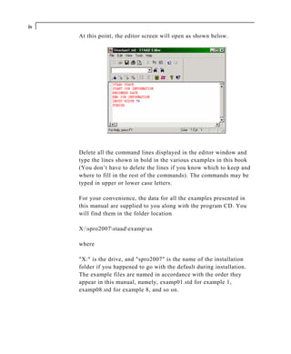
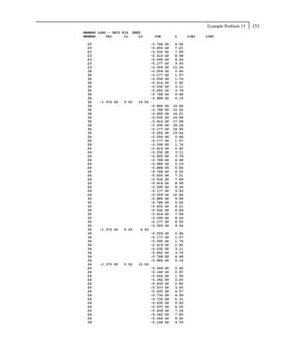
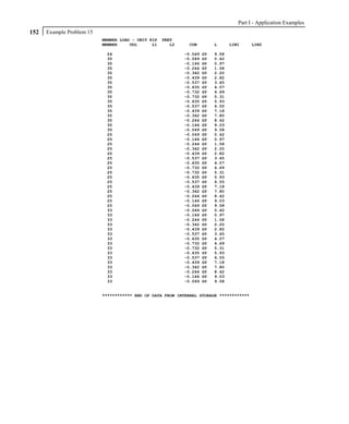
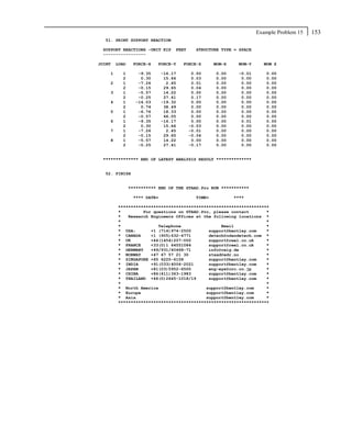
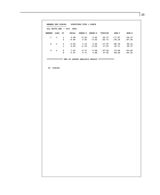
Downloaded 640 times


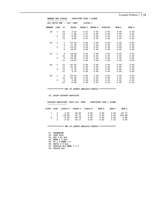
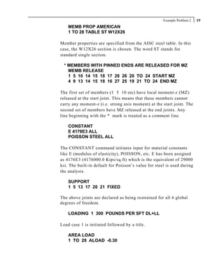


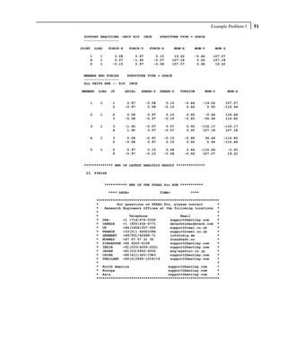

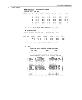


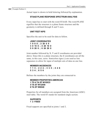


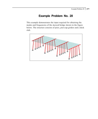
![Part I - Application Examples
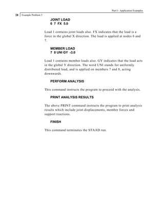
284 Example Problem 28
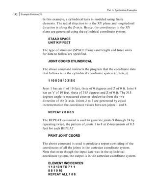
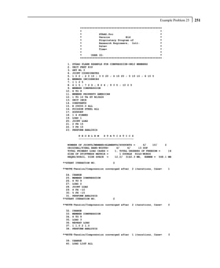
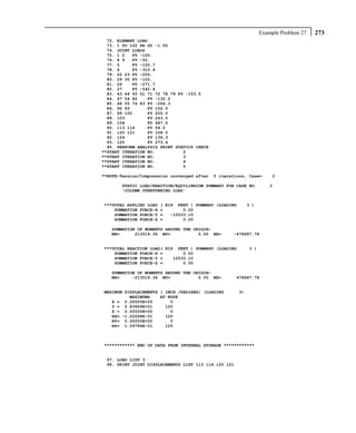
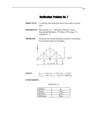
The method involves 2 matrices - the stiffness matrix, and the
mass matrix.
The stiffness matrix, usually called the [K] matrix, is assembled
using data such as member and element lengths, member and
element properties, modulus of elasticty, Poisson's ratio, member
and element releases, member offsets, support information, etc.
For assembling the mass matrix, called the [M] matrix, STAAD
uses the load data specified in the load case in which the MODAL
CAL REQ command is specified. So, some of the important
aspects to bear in mind are :
1. The input you specify is weights, not masses. Internally,
STAAD will convert weights to masses by dividing the input
by "g", the acceleration due to gravity.
2. If the structure is declared as a PLANE frame, there are 2
possible directions of vibration - global X, and global Y. If
the structure is declared as a SPACE frame, there are 3
possible directions - global X, global Y and global Z.
However, this does not guarantee that STAAD will
automatically consider the masses for vibration in all the
available directions.
You have control over and are responsible for specifying the
directions in which the masses ought to vibrate. In other
words, if a weight is not specified along a certain direction,
the corresponding degrees of freedom (such as for example,
global X at node 34 hypothetically) will not receive a
contribution in the mass matrix. The mass matrix is
assembled using only the masses from the weights and
directions specified by the user.
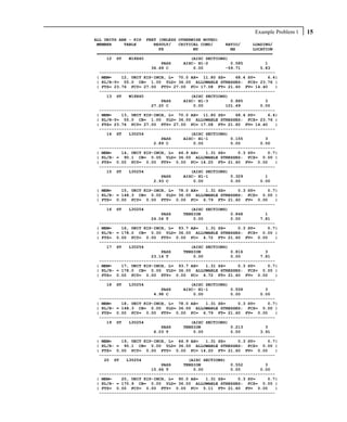
In our example, notice that we are specifying the selfweight
along global X, Y and Z directions. Similarly, a 200 kg/sq.m
pressure load is also specified along all 3 directions on the
deck.](https://image.slidesharecdn.com/americanappexamples2007complete-111004044110-phpapp02/85/American-app-examples_2007_complete-304-320.jpg)


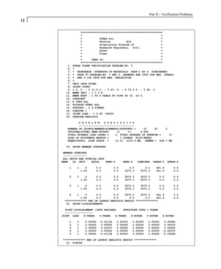
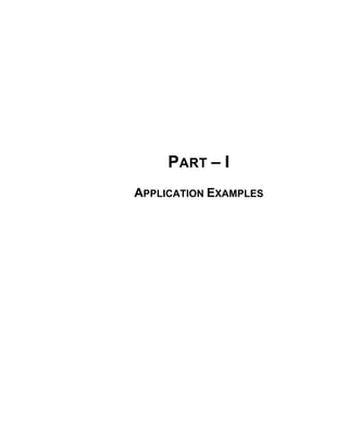
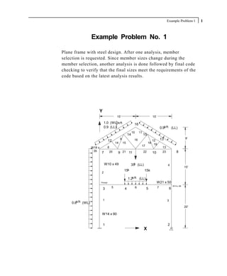
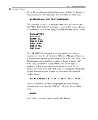
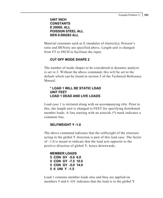
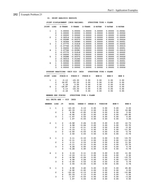
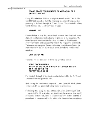
![Part II – Verification Problems
32
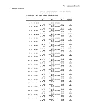
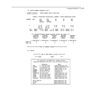
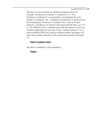
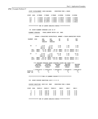
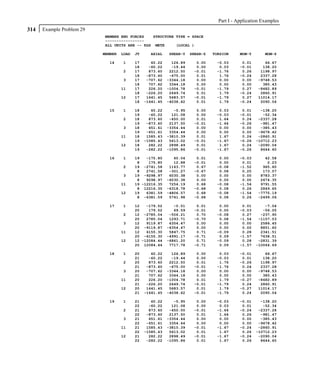
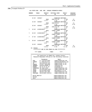
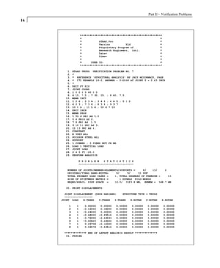
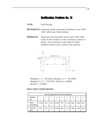
VERIFICATION PROBLEM 13 HAND CALCULATION
Manual / Code refers to AISC Manual of Steel Construction,
Allowable Stress Design, ninth edition.
Steel Design -
Member 1, Size W 12X26, L = 10 ft., a = 7.65 in 2 , Sz = 33.39 in 3
From clause F1-2, page 5-45 of Manual, L c = 6.85 ft.
From observation Load case 1 will govern,
Fx = 25.0 kip (compression), Mz = 56.5 k-ft
Area of compressive flange = 6.49*0.38 = 2.466 sq.in.
Allowable bending stress = F b = 12. x 1000 x 1.0 = 20.1817 ksi [Clause F1-8
10 x 12 x (12.22/2.466) page 5-47
of Manual]
(kl/r)y = 120/1.5038 = 79.8, so Fa = 15.38 ksi (Table C-36
page 3-16 of manual)
fa = 25./7.65 = 3.268, fb = 56.5 x 12/33.39 = 20.31 ksi
(kl/r)z = 120/5.1639 = 23.238, so F’ez = 276.54 ksi
Try formula H1-1, page 5-54 of Manual
3.268 + 0.85 x 20.31 = 1.078
15.38 (1-3.268/276.54) x 20.1817
Try formula H1-2, page 5-54 of Manual.
3.268 + 20.31 = 1.1576
0.6 x 36 20.1817
Therefore formula H1-2 governs and ratio = 1.1576](https://image.slidesharecdn.com/americanappexamples2007complete-111004044110-phpapp02/85/American-app-examples_2007_complete-374-320.jpg)
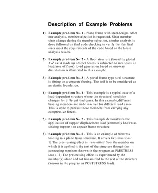
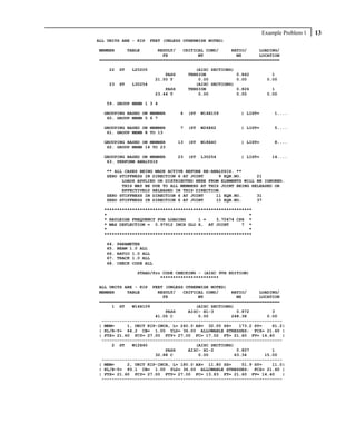
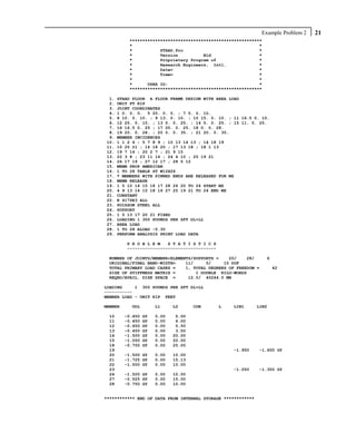
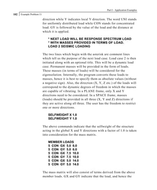
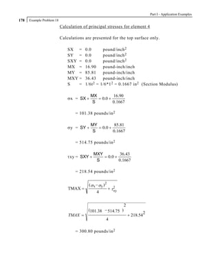
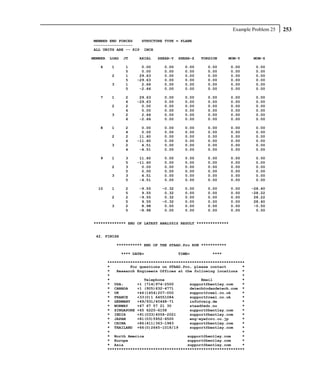
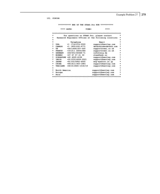
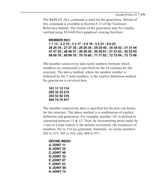
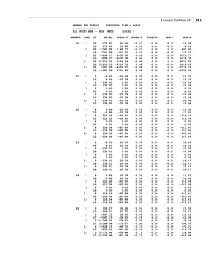
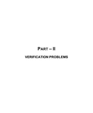
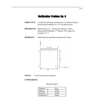
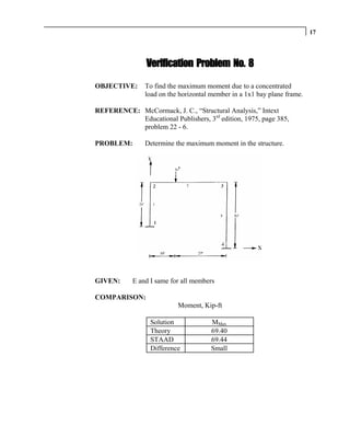
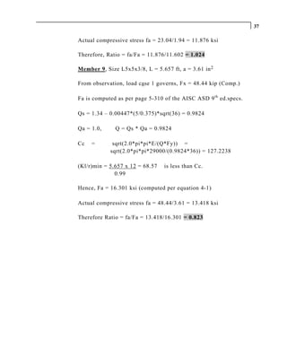
![33
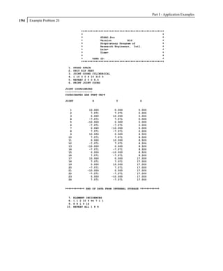
Member 2, Size W12X26, L = 5 ft., a = 7.65 in 2 , Sz = 33.39 in 3
From observation load case 1 will govern,
Fx = 8.71 kip (compression), Mz = 56.50 k-ft
Since L is less than L c (6.85ft) [Clause F1-2
page 5-45 of Manual]
Fb = 0.66x36 = 23.76 ksi (Clause F1-1
page 5-45 of Manual)
(kl/r)y = 60/1.5038 = 39.90, so Fa = 19.19 ksi Table C-36
page 3-16 of Manual
fa = 8.71/7.65 = 1.1385, fb = 56.5 x 12/33.39 = 20.31 ksi
Since fa/Fa less than 0.15, apply formula H1-3, page 5-54 of
Manual
1.1385 + 20.31 = .0593 + .8548 = 0.9141
19.19 23.76
Member 3, Size W14X43, L = 11ft., a = 12.6 in 2 , Sz = 62.7 in 3
From observation load case 3 will govern,
Fx = 25.5 kip (compression), Mz = 112.173 k-ft
Refering to clause F1-2, page 5-45 of Manual.
L c = 8.4 ft. Therefore, Fb = 0.6 x 36 = 21.6 ksi
(kl/r)y = 132/1.8941 = 69.69, so Fa = 16.46 ksi [Table C-36
page 3-16 of Manual]
fa = 25.5/12.6 = 2.024, fb = 112.173 x 12/62.66 = 21.48 ksi
since fa/Fa less than 0.15, use formula H1-3, page 5-54 of Manual](https://image.slidesharecdn.com/americanappexamples2007complete-111004044110-phpapp02/85/American-app-examples_2007_complete-375-320.jpg)
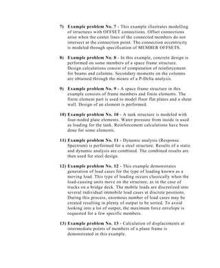
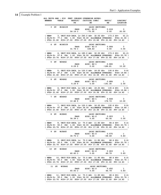
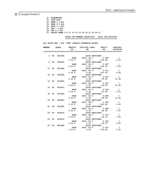
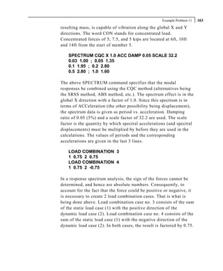
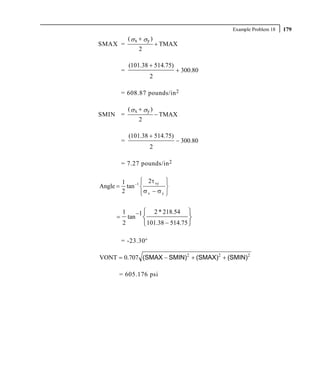
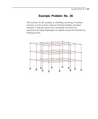
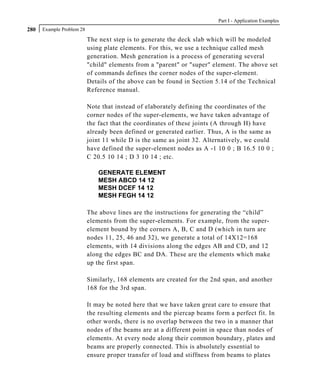
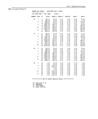
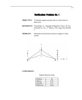
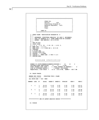
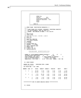
![Part II – Verification Problems
34
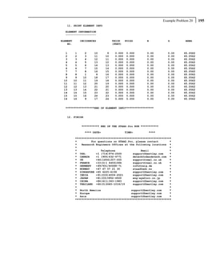
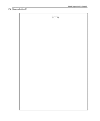
2.024 + 21.48 = 0.123 + 0.994 = 1.117
16.46 21.6
Member 4, Size W14X43, L = 4ft, a = 12.6 in 2 , Sz = 62.7 in 3
From observation, load case 3 will govern,
Fx = 8.75 kip (tension), Mz = 112.173 k-ft
L c = 8.4 ft
Since L is less than L c
Fb = 0.66 x 36 = 23.76 ksi [Clause F1-1
page 5-45 of Manual]
f a = 8.75/12.6 = 0.694, f b = 112.73x12/62.66 = 21.48 ksi
Combined tension and bending, use formula H 2-1, page 5-55 of
Manual.
0.694 + 21.48 = 0.032 + 0.904 = 0.936
0.6 x 36 23.76
Member 5, Size W16X36, L = 5ft, a = 10.6 in 2 , Sz = 56.49 in 3
L c =7.37 ft, [Clause F1-2
page 5-45 of Manual.
From observation, load case 3 will govern.
Fx = 14.02 kip (compression), Mz =57.04 k-ft
Since L is less than L c ,
Fb = 0.66 x 36 = 23.76 ksi
(kl/r)y = 60./1.52 = 39.47, so Fa = 19.23 ksi [Table C-36
page 3-16 of Manual]
fa = 14.02/10.6 = 1.32, fb = 57.04 x 12/56.5 = 12.12 ksi](https://image.slidesharecdn.com/americanappexamples2007complete-111004044110-phpapp02/85/American-app-examples_2007_complete-376-320.jpg)
![35
Since fa/Fa less than 0.15, use formula H1-3, page 5-54 of Manual
1.32 + 12.12 = 0.069 + 0.510 = 0.579
19.23 23.76
Member 6, Size W16X36, L = 16ft, a = 10.6 in 2 , Sz = 56.49 in 3
From observation, load case 1 will govern. Forces at midspan are
Fx = 5.65 kip (compression), Mz = 71.25 k-ft
From Chapter F of the AISC ASD 9 th ed. specs., with Cb = 1.0,
sqrt(102,000C b /F y) =53.229
sqrt(510,000C b /F y) =119.02
L/r T = 192/1.79 = 107.26
53.229 < 107.26 < 119.02
Therefore F b (as per F1-6, page 5-47 of Manual)
[(2/3) – 36*107.26*107.26/(1530,000)]*36 = 14.25 ksi
(Kl/r)y = 192/1.5203 = 126.29, so Fa = 9.36 [Table C-36
page 3-16 of Manual]
fa = 5.65/10.6 = 0.533, fb = 71.25x12/56.49 = 15.14 ksi
Since fa/Fa less than 0.15 use formula [H1-3, page 5-54 of
Manual]
0.533/9.36 + 15.14/14.25 = 0.057 + 1.062 = 1.119](https://image.slidesharecdn.com/americanappexamples2007complete-111004044110-phpapp02/85/American-app-examples_2007_complete-377-320.jpg)
![Part II – Verification Problems
36
Member 7, Size W16X36, L =4ft, a = 10.6in 2 , Sz =56.49in 3
Lc = 7.37ft (Clause F1-2 page 5-45 of Manual)
From observation load case 3 will govern, Fx = 24.06 kip
(tension), M z = 62.96 k-ft
From Clause F1-1, Fb = 0.66 Fy = 23.76 ksi = allowable
compressive stress.
Since section is in tension, Fb = 0.60X36 = 21.60 Ksi [Clause F1-
5, page5-45 of Manual].
Choosing the larger of above 2 values, Fb = 23.76 Ksi
fa = 24.06/10.6 = 2.2698, fb = 62.96X12/56.49 = 13.37
Since combined tension and bending, use formula H 2-1, page 5-55
of the AISC ASD 9 th ed. specs.
2.2698 + 13.37 = 0.105 + 0.5627 = 0.6677
0.6 x 36 23.76
Member 8, Size L4x4x1/4, L = 7.071 ft, a = 1.94 in 2
From observation load case 1 will govern, Fx = 23.04 kip (Comp.)
Fa is computed as per page 5-310 of the AISC ASD 9 th ed.specs.
Qs = 1.34 – 0.00447*(4/0.25)*sqrt(36) = 0.9108
Qa = 1.0, Q = Qs * Qa = 0.9108
Cc = sqrt(2.0*pi*pi*E/(Q*Fy)) =
sqrt(2.0*pi*pi*29000/(0.9108*36)) = 132.1241
Kl/r = 7.071 x 12 = 106.73 is less than Cc.
0.795
Hence, Fa = 11.6027 ksi (computed per equation 4-1)](https://image.slidesharecdn.com/americanappexamples2007complete-111004044110-phpapp02/85/American-app-examples_2007_complete-378-320.jpg)

STAAD.Pro 2007 is a structural analysis and design software. It contains tools for creating structural models, performing analyses like linear elastic and finite element analysis, structural design, viewing and verifying results, and generating reports. The documentation for STAAD.Pro includes manuals that describe the graphical user interface, provide usage examples, and explain the underlying engineering calculations and command language.


