
![Chapter 3: Starting ALH
Path Requirements
Before invoking the Alarm Handler for the first time, the path to the executable and configuration files must
be established. Contact your EPICS administrator to find the locations of the Alarm Handler executable, alh,
and your site's Alarm Handler configuration input files.
Environment Variables
ALARMHANDLER
The optional environment variable ALARMHANDLER can be used to point the Alarm Handler to a desired
working directory. If ALARMHANDLER is not set, the current working directory is assumed. If the alarm
configuration file resides in a different directory (e.g. /home/cs/appl/ah/dev) from the current working
directory, under UNIX ALARMHANDLER can be set to point to the desired path by issuing the UNIX c shell
command:
setenv ALARMHANDLER /home/cs/appl/ah/dev
The user must have read and write privileges in this directory.
ALHMAINFONT
The environment variable ALHMAINFONT may be used to set the Runtime Window button font e.g.
export ALHMAINFONT='−*−utopia−bold−r−normal−−0−720−75−75−p−0−*−*'
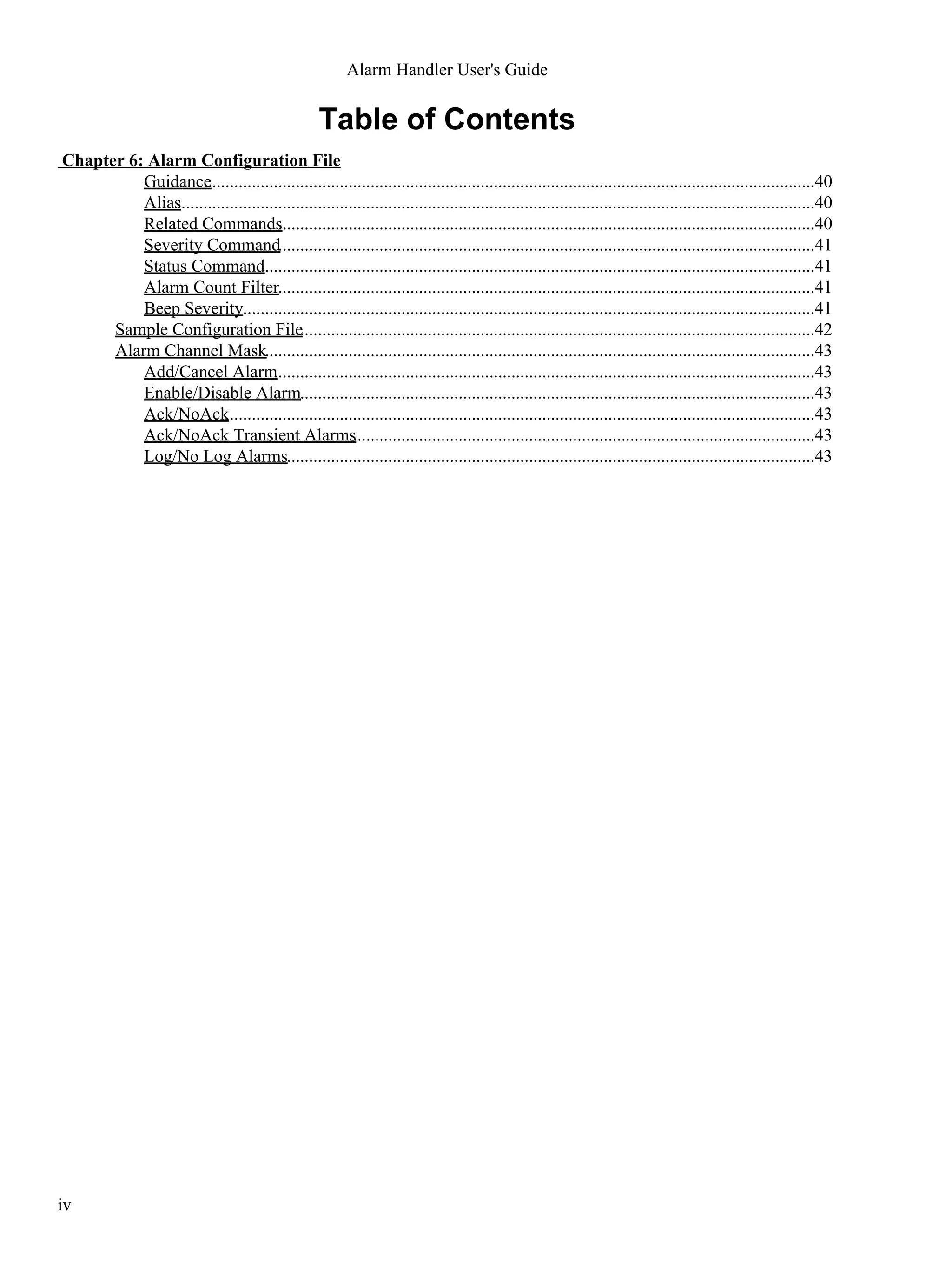
Command Line Syntax
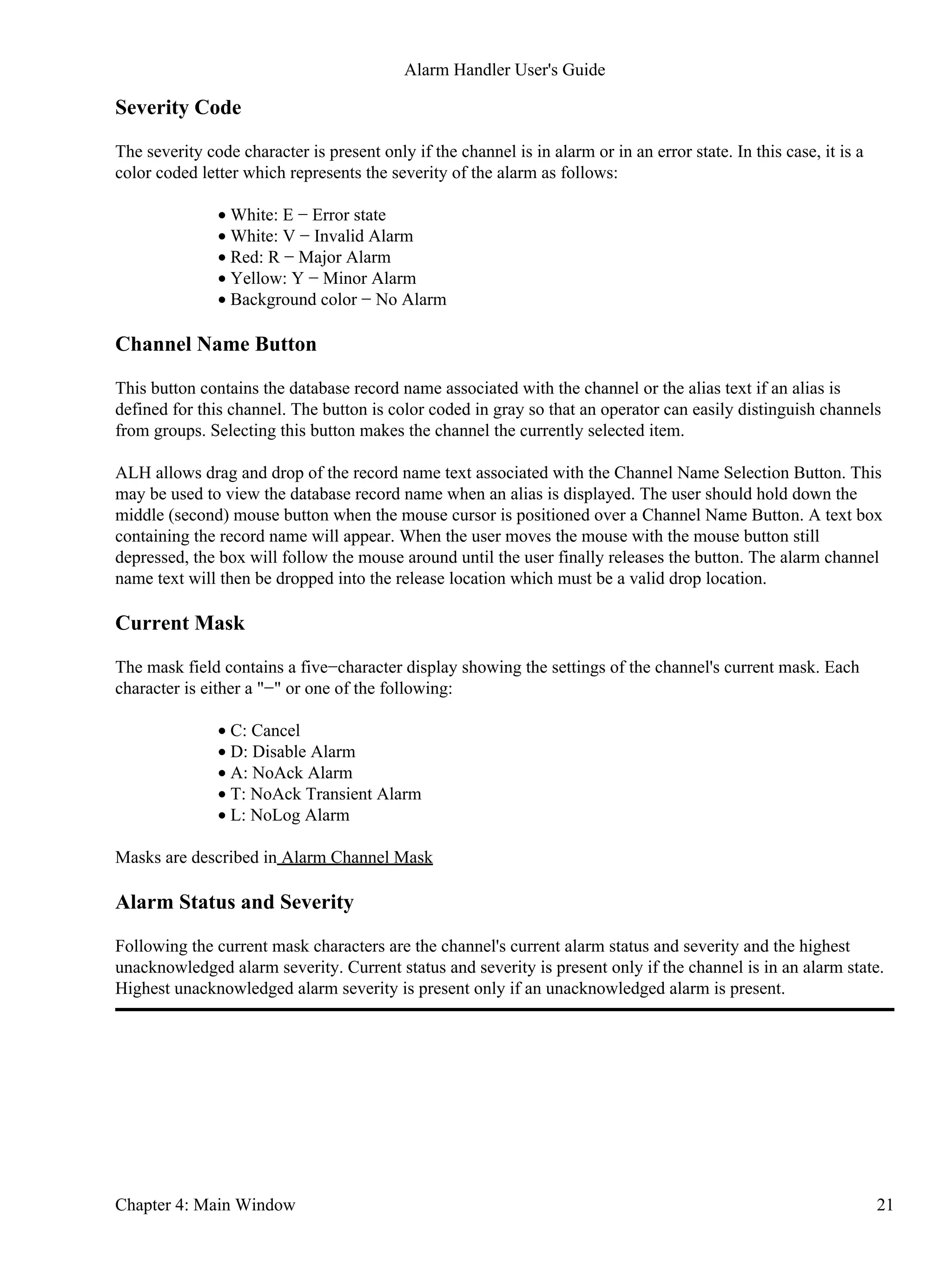
Once the path is properly set, invoke the Alarm Handler by executing the command:
alh
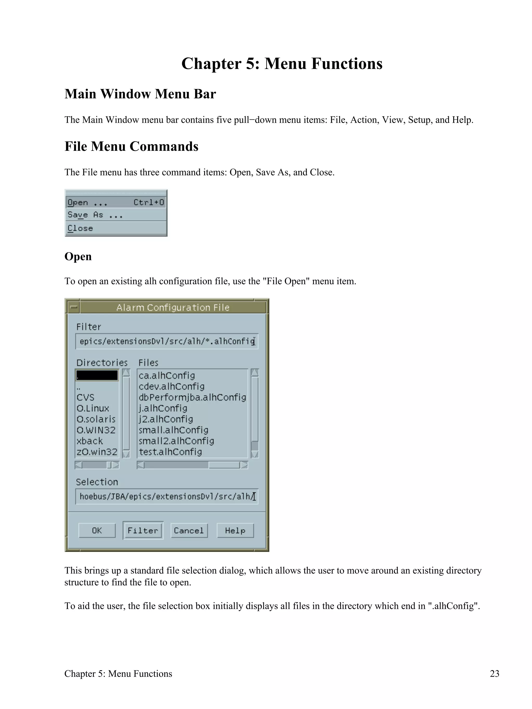
This command displays a file selection box in which to specify an alarm configuration file name. The default
path for files is the directory defined by the ALARMHANDLER environment variable or the current directory
and the default alarm handler output file names are ALH−default.alhAlarm and ALH−default.alhOpmod . If
there is an alarm configuration file in the current directory with the name ALH−default.alhConfig, it will be
used as the input configuration file.
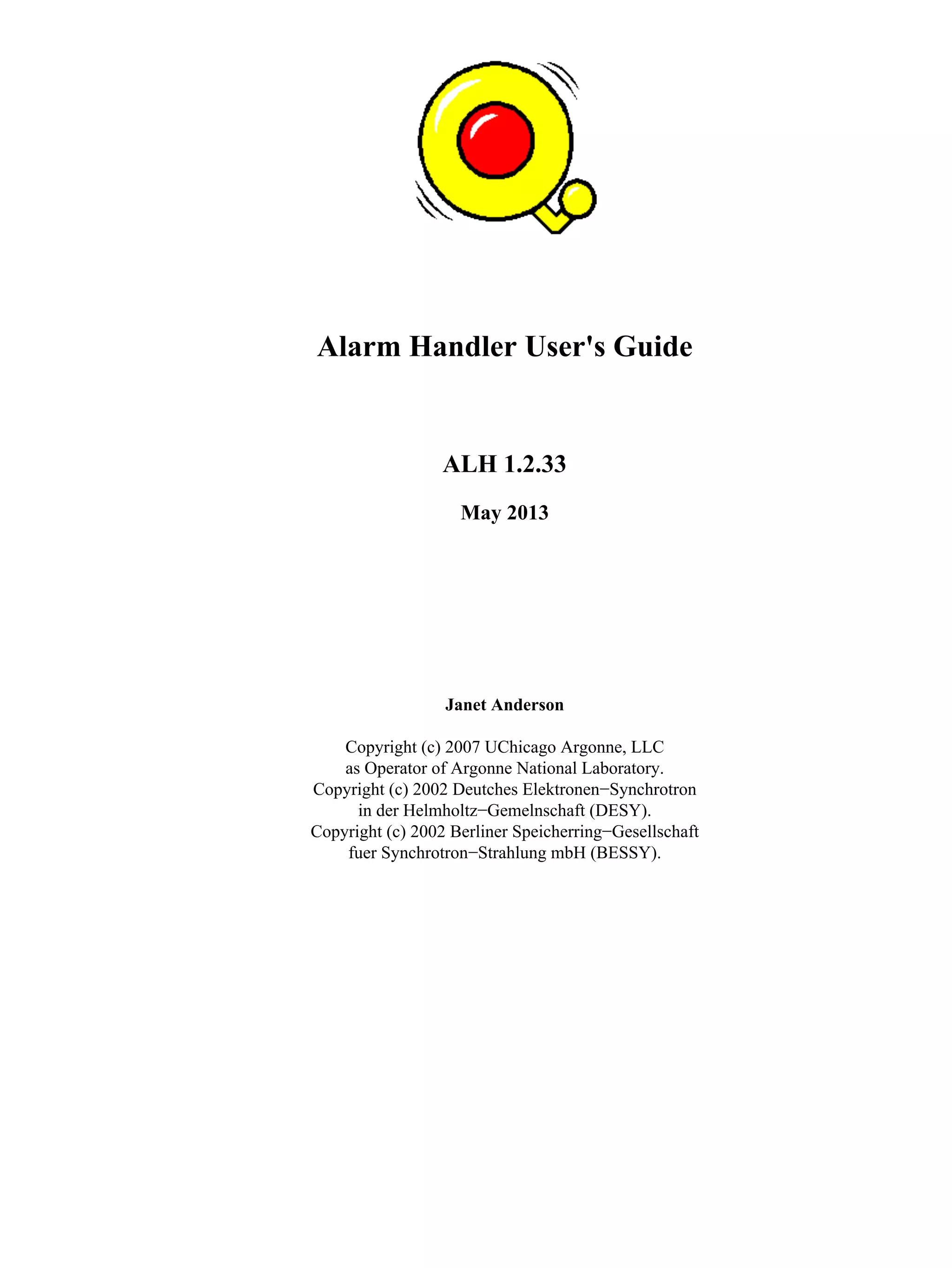
The Alarm Handler command has several options and a usage message similar to the table below will be
displayed if you enter: "alh −help".
alh [OPTIONS] [Xoptions] [configfile]
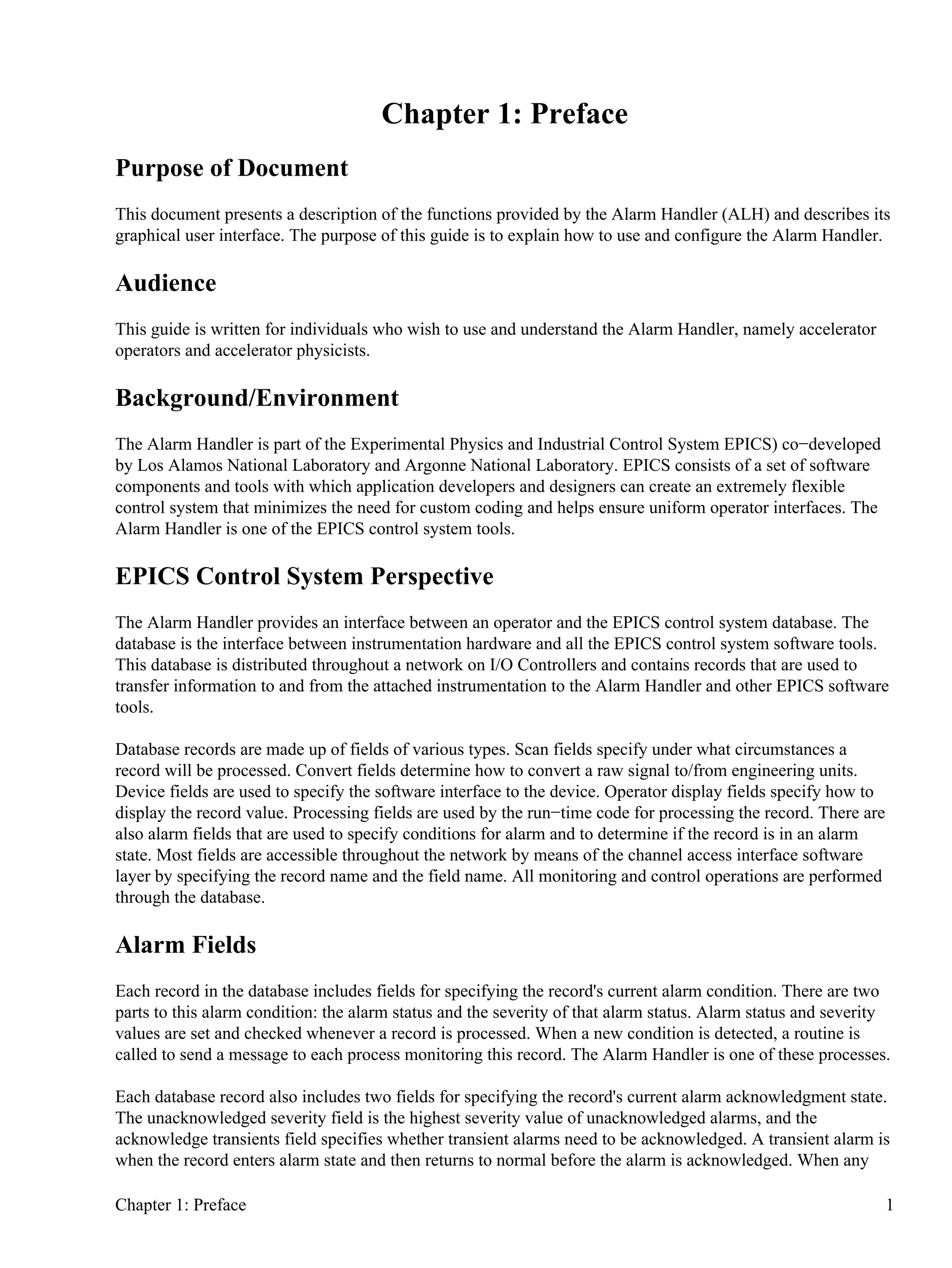
The alarm handler options are:
−a alarmlogfile Alarm log filename [ALH−default.alhAlarm
Chapter 3: Starting ALH 7](https://image.slidesharecdn.com/alhuserguide-1-140627181129-phpapp01/75/ALH-user-guide-1-2-33-May-2013-13-2048.jpg)
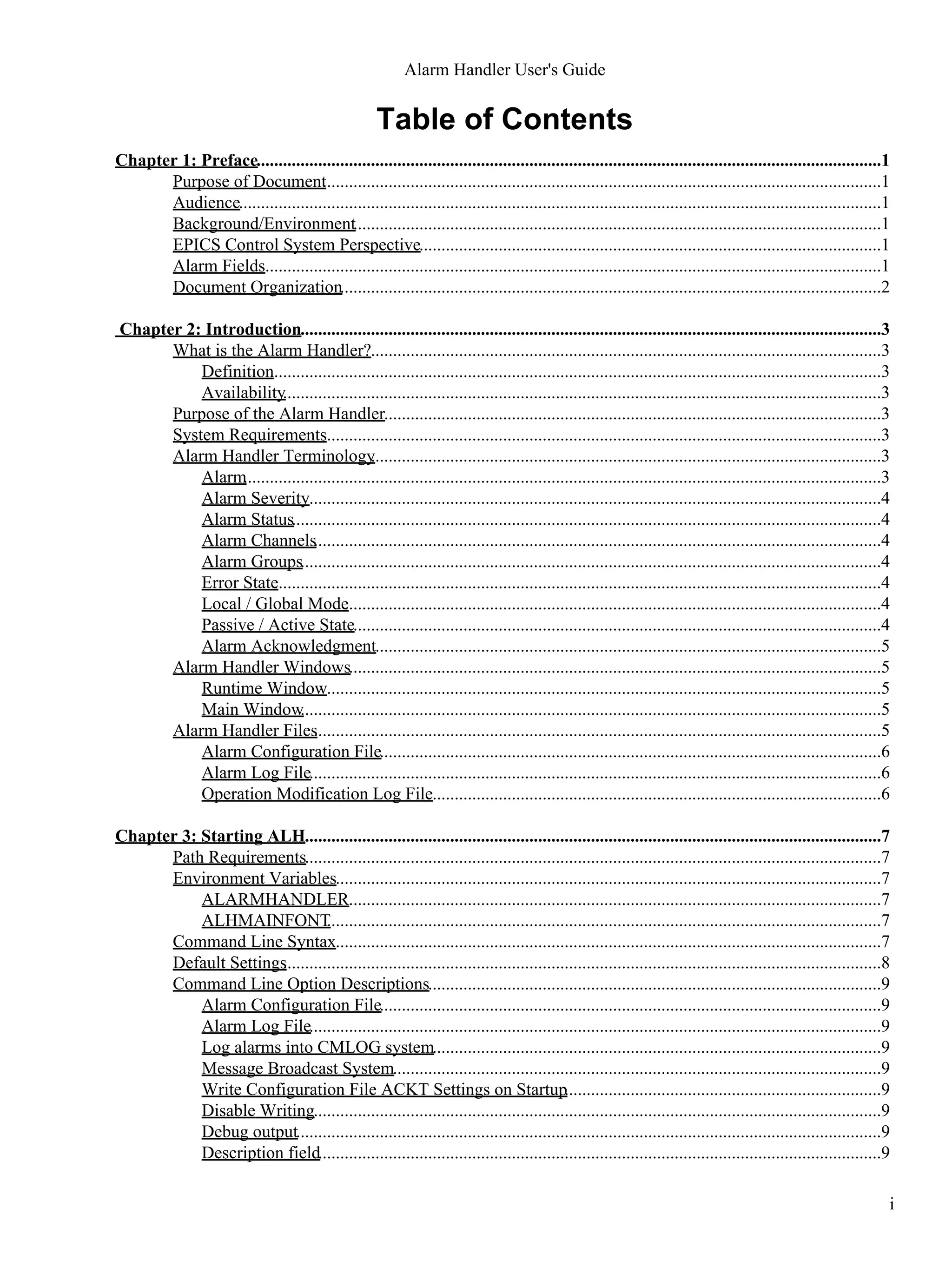
![−aCM Alarm log using CMLOG (if built using CMLOG)
−B Message Broadcast System
−caputackt Caput the config file ackt settings to channels (if global and active)
−D Disable alarm and opMod log output
−debug Debug output will be sent to stdout
−desc_field Put DESC field text on alarm log lines
−f filedir Directory for alarm configuration files [.]
−filter f−opt
Set alarm display filter with f−opt being one of [nau]
n[0]: no filter
a[ctive]: show only active alarms
u[nack]: show only unacknowledged alarms
−global Global mode (channel ACKS and ACKT fields)
−help Print usage text to stdout
−L Use Locking System
−Lfile lockfile Basename for .LOCK lock file
−l logdir Directory for log files [.]
−m maxrecords Alarm log file maximum records [2000]
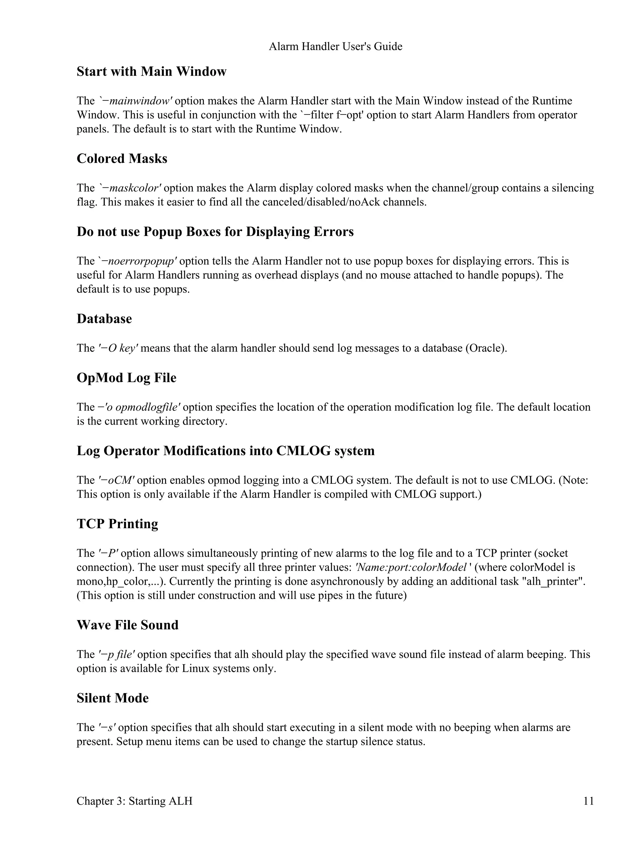
−mainwindow Start with Main Window
−maskcolor
Print mask colored when channel/group contains silencing flag
(makes it easier to find all canceled/disabled/noAck channels)
−noerrorpopup Do not display error popup window (errors are logged)
−O key Log to database (Oracle)
−o opmodlogfile Opmod log filename [ALH−default.alhOpmod]
−oCM OpMod log using CMLOG
−P key Print to TCP printer
−p file Use wave file for sound instead of alarm beep (OS dependent)
−S Passive state (no ca_puts to ACKS and ACKT fields and severity PV)
−s Silent execution (no alarm beeping)
−T Alarm Log Dated output files
−v, −version Print version number
−xml Use XML−ish format for log files
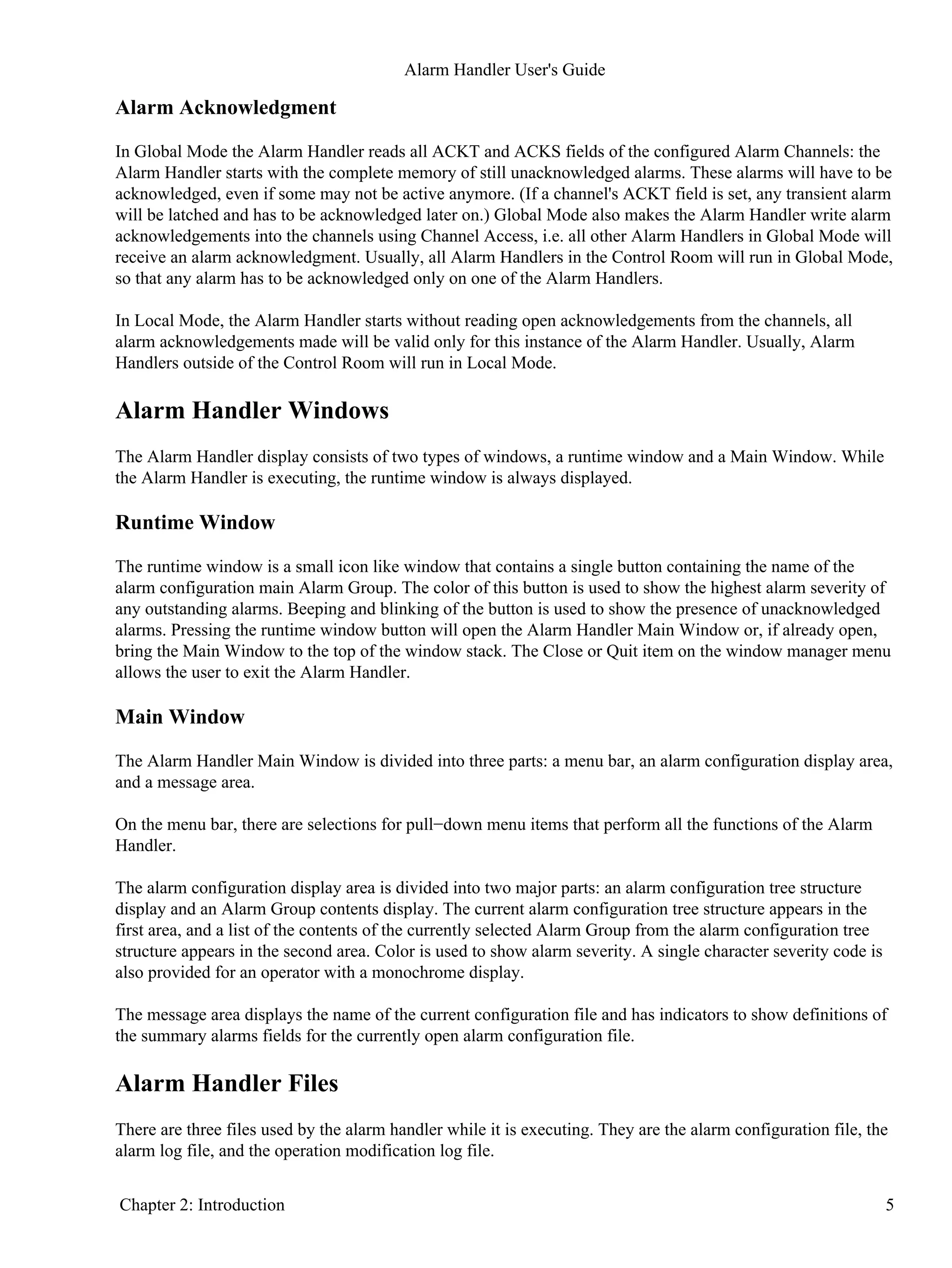
Default Settings
The default settings for ALH (Alarm Handler) are as follows:
Local mode•
Active state•
Alarm log file maximum records 2000•
Directory for files: ALARMHANDLER if defined else current directory•
Alarm Configuration File: ALH−default.alhConfig•
Alarm Log File: ALH−default.alhAlarm•
Operator Modification Log File: ALH−default.opmod•
Save New Configuration File: ALH−new.alhConfig•
Beeping Status: On•
Severity for Beeping: Minor (i.e. any non−zero severity)•
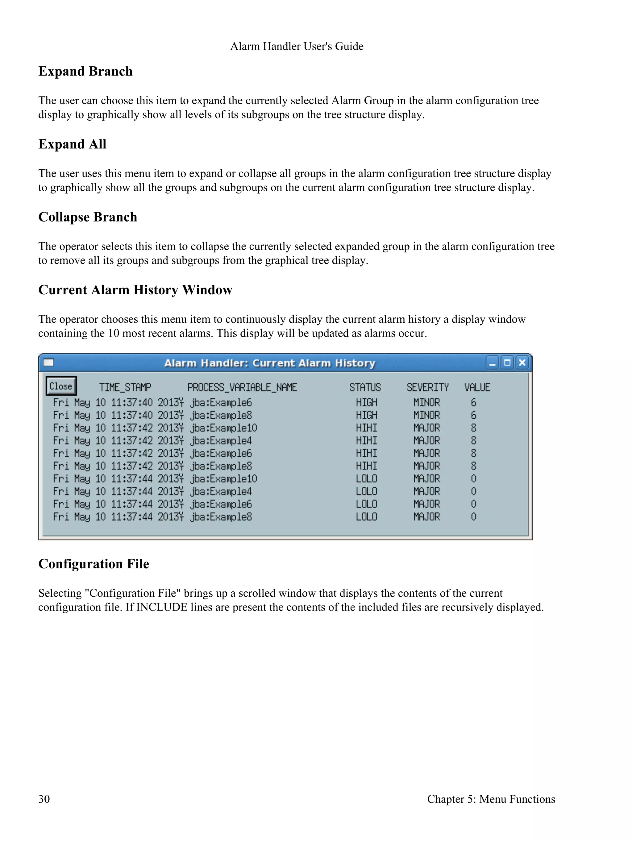
Alarm Handler User's Guide
8 Chapter 3: Starting ALH](https://image.slidesharecdn.com/alhuserguide-1-140627181129-phpapp01/75/ALH-user-guide-1-2-33-May-2013-14-2048.jpg)
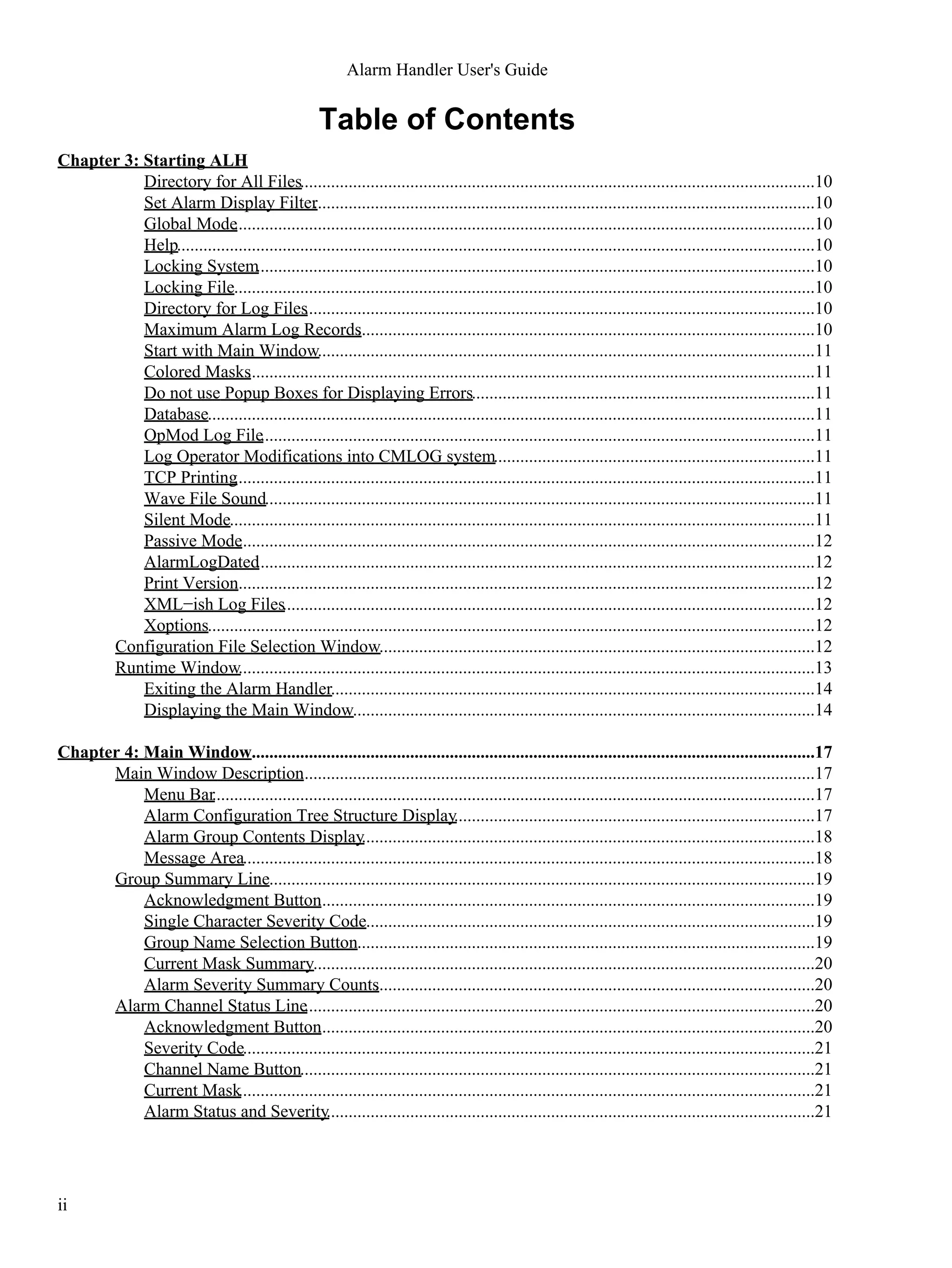
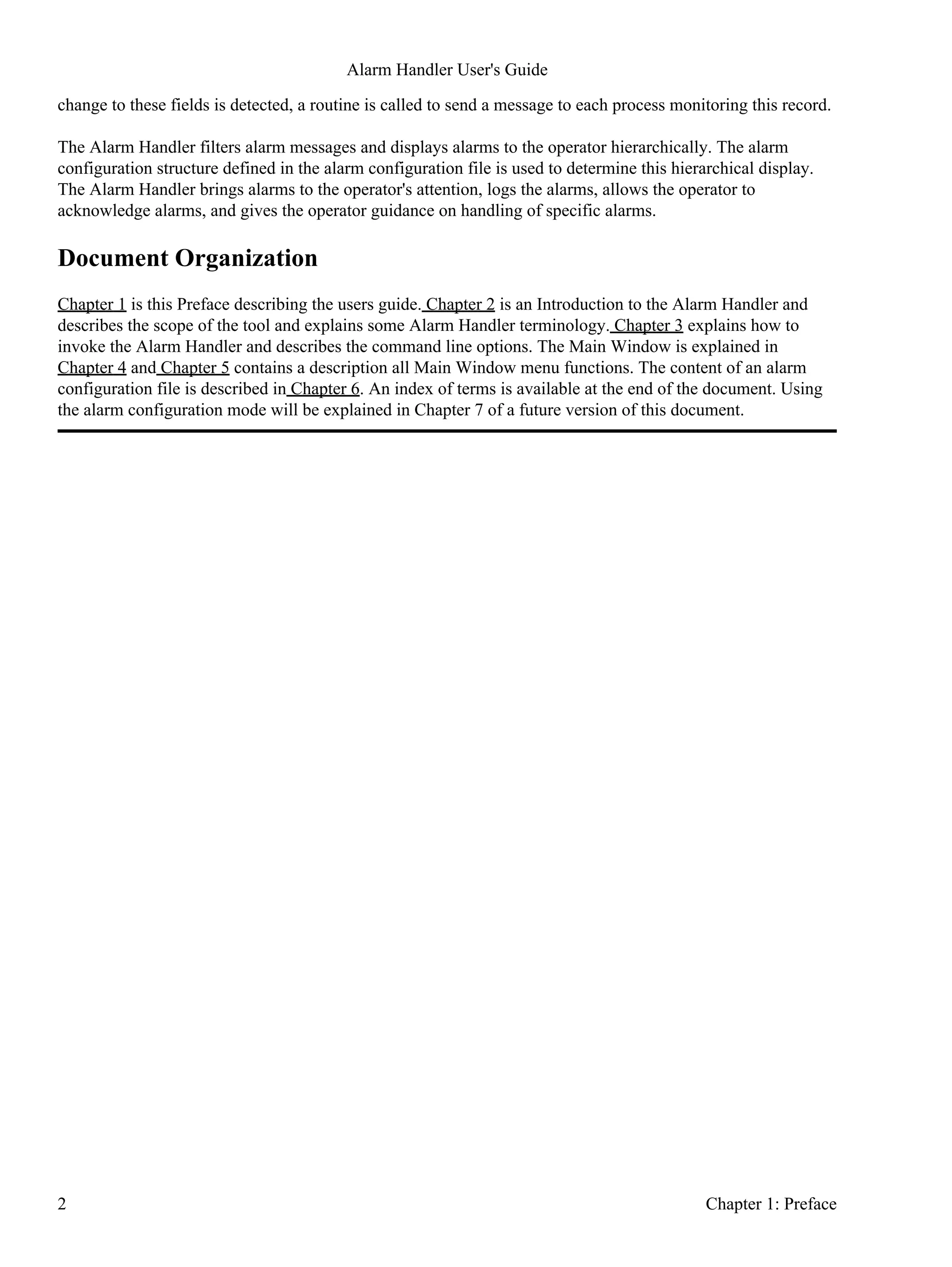
![Directory for All Files
The '−f filedir ' option specifies the directory for the Alarm Handler input and output files. The default
location is the current working directory.
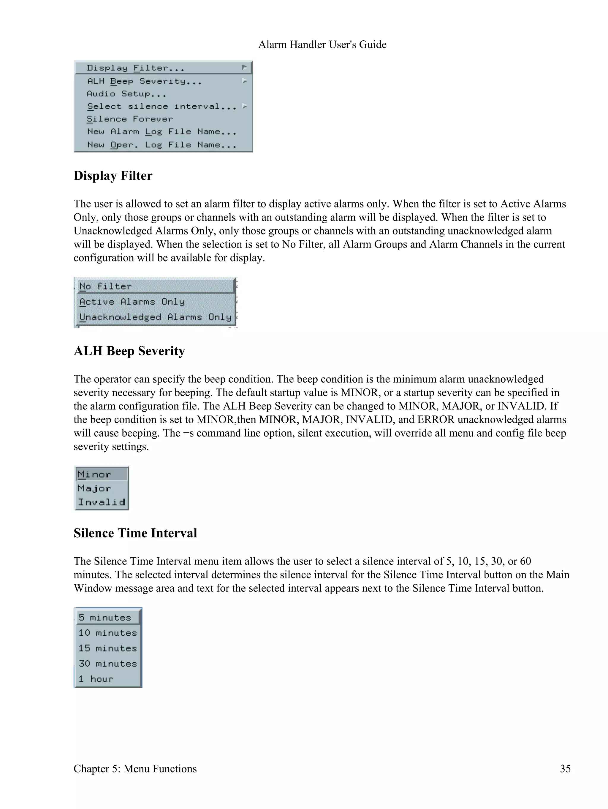
Set Alarm Display Filter
The '−filter f−opt' option sets the initial alarm display filter for the Alarm Handler (see −>>Menu
Functions−>Setup Menu−>Display Filter). `f−opt' may be one of `n[o]' (for no filter), `a[ct]' (show active
alarms) or `u[nack]' (show only unacknowledged alarms). Default is `no', i.e. all Alarm Groups and channels
in the current configuration will be displayed. This option is particularly useful in combination with
`−mainwindow' to start Alarm Handlers from operator panels.
Global Mode
The '−global' options specifies that the alarm handler should run in a global mode. In global mode an Alarm
Channel's unacknowledged severity and it's acknowledge transients state will be determined by the current
value of the EPICS database record's ACKS and ACKT field settings. In local mode, the default mode, the
unacknowledged severity and acknowledge transients settings are local to the alarm handler.
Help
The '−help' option will print alh command usage text to stdout.
Locking System
The '−L' option activates a file locking system (based on lockf(), i.e. NFS−safe) making sure that only one of
multiple Alarm Handlers with enabled log writing has access to the log. If the `master' (i.e. actively logging)
process dies, another Alarm Handler will seamlessly take over logging. Default is not to use this locking
mechanism.
Locking File
The '−L lockfile' option specifies a lock file directory with file name prefix. A ".LOCK" suffix will be
appended. The default is the configure filename with directory from the −f option or the current working
directory.
Directory for Log Files
The '−l logdir' option specifies the location of the alarm log file and the operation modification log file. The
default location is the current working directory.
Maximum Alarm Log Records
The '−m maxrecords' option allows the user to specify the maximum number of records that the alarm handler
will allow in the alarm log file. If this number of records is reached, new records will overwrite old alarm
records. The default number of records is 2000. Specifying zero means the file can have an unlimited number
of records.
Alarm Handler User's Guide
10 Chapter 3: Starting ALH](https://image.slidesharecdn.com/alhuserguide-1-140627181129-phpapp01/75/ALH-user-guide-1-2-33-May-2013-16-2048.jpg)
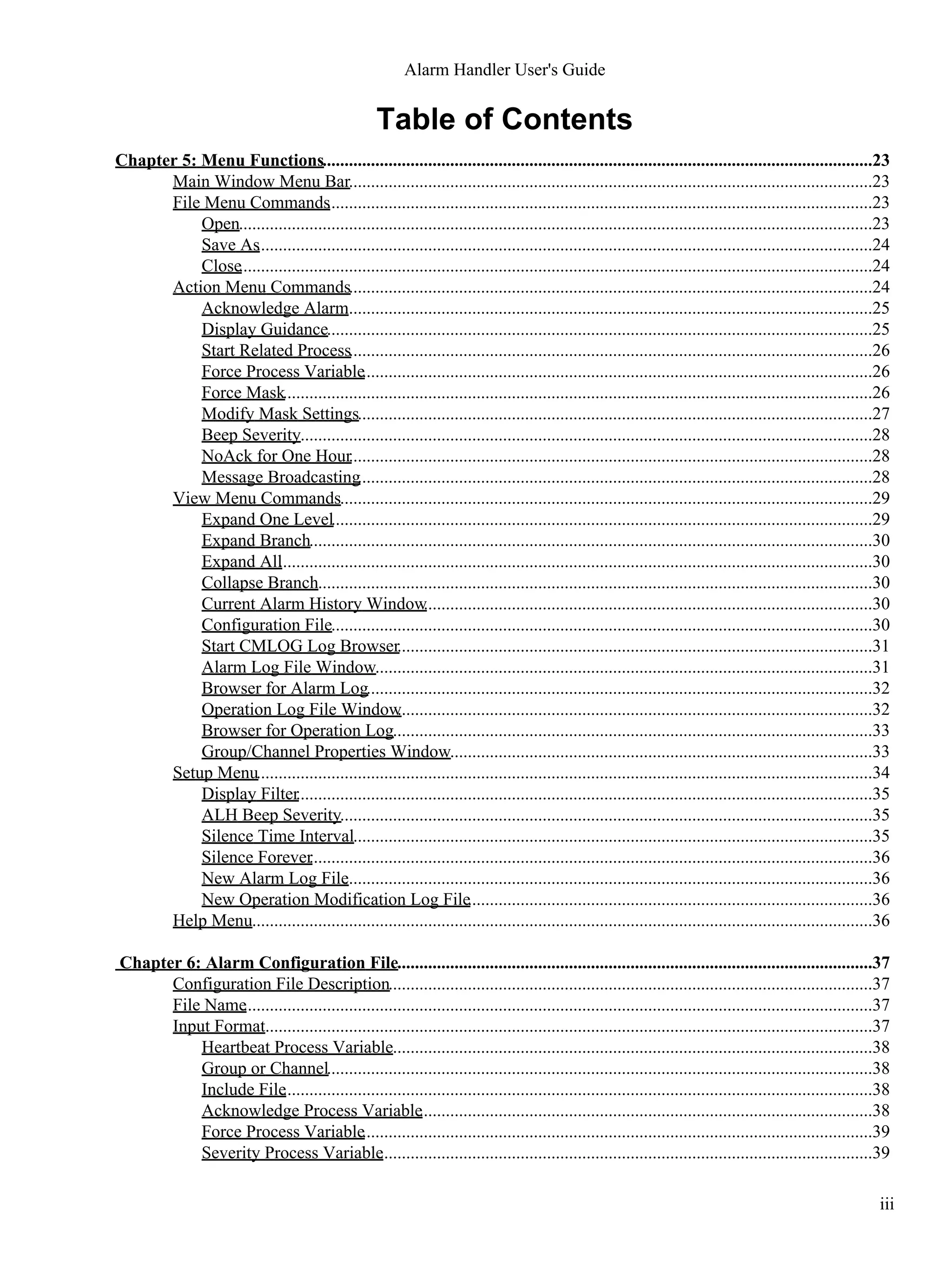
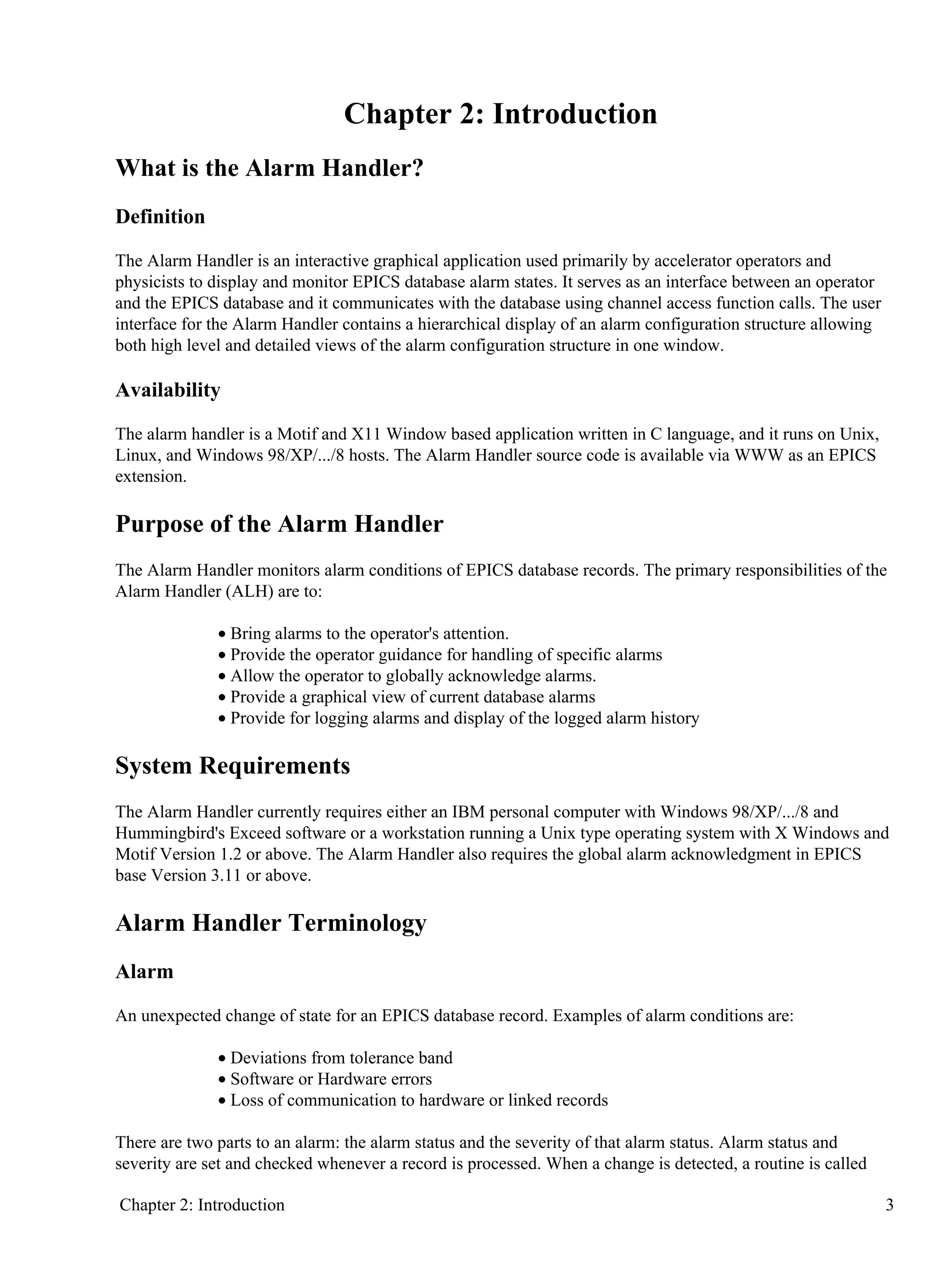
![Passive Mode
Specifying this '−S' option means that the alh will execute in a passive (monitor) mode. This means that alh
can not send channel access acknowledgment of alarms and can not do channel access puts to the
acknowledge transients fields and cannot write to the severity process variable. It is useful for a non−operator
alh user.
AlarmLogDated
With the '−T' option, alarmLog file names will have "date" extensions like YYYY−MM−DD, and log files are
automatically switched at midnight. For this option, there is a Main Window menu browser that is displayed
after pressing View−"Alarm Log File Window". This browser allows searches in the AlarmLogFile and find
all alarms inside of [t1,t2]−diapason containing some <String>.
Print Version
The '−v' or '−version' option specifies that the Alarm Handler version number should be printed to stdout.
XML−ish Log Files
The '−xml' option specifies that the Alarm Handler log files should be written in Extensible Markup Language
(XML).
Xoptions
When executing on Unix, the 'alh' command line accepts all X options such as '−bg color_name' and '−fg
color_name' and '−geometry geom_spec'
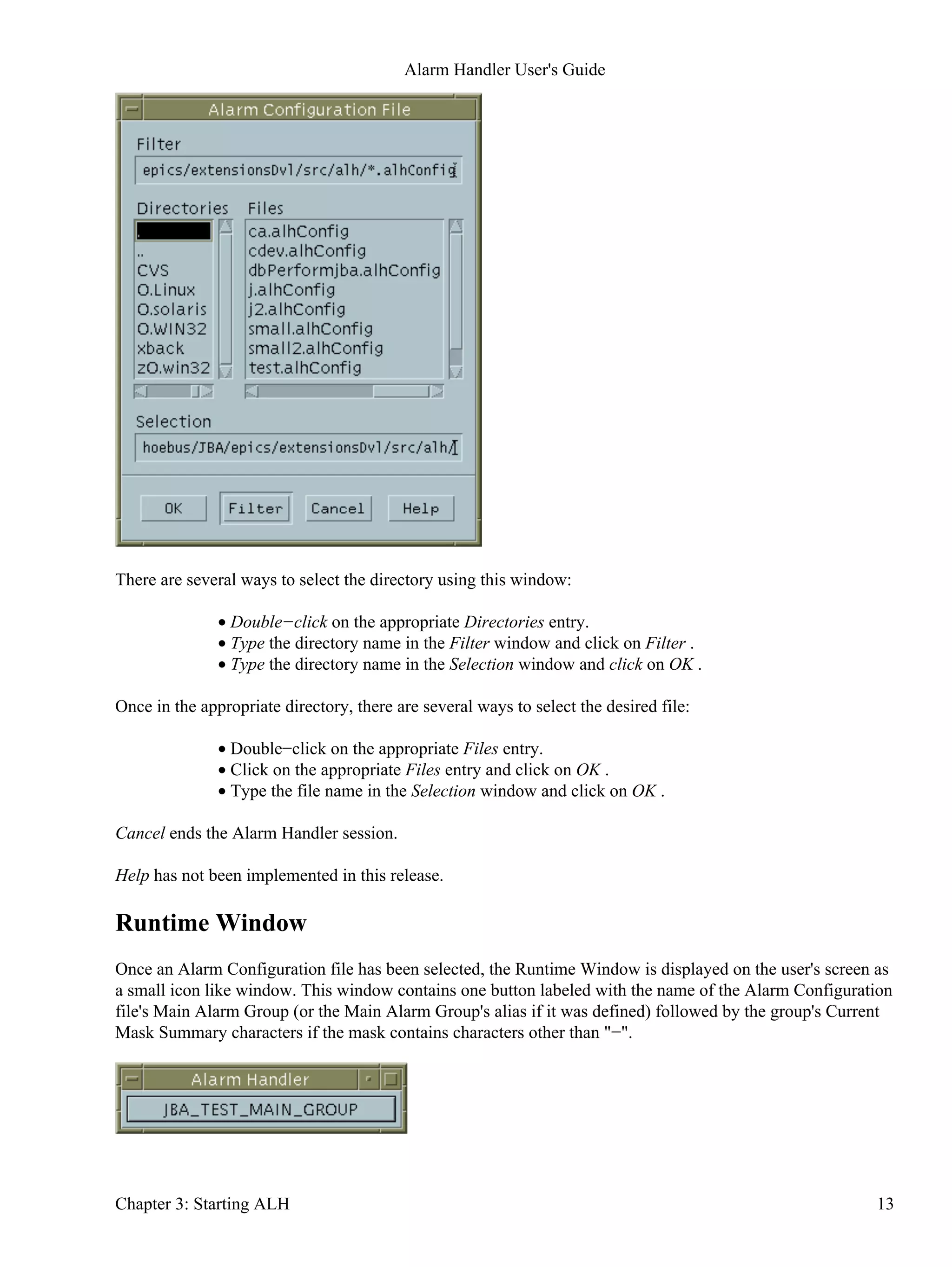
Configuration File Selection Window
If the Alarm Configuration file is not specified on the command line, a file selection window is presented so
the user can select the desired Alarm Configuration file
Alarm Handler User's Guide
12 Chapter 3: Starting ALH](https://image.slidesharecdn.com/alhuserguide-1-140627181129-phpapp01/75/ALH-user-guide-1-2-33-May-2013-18-2048.jpg)


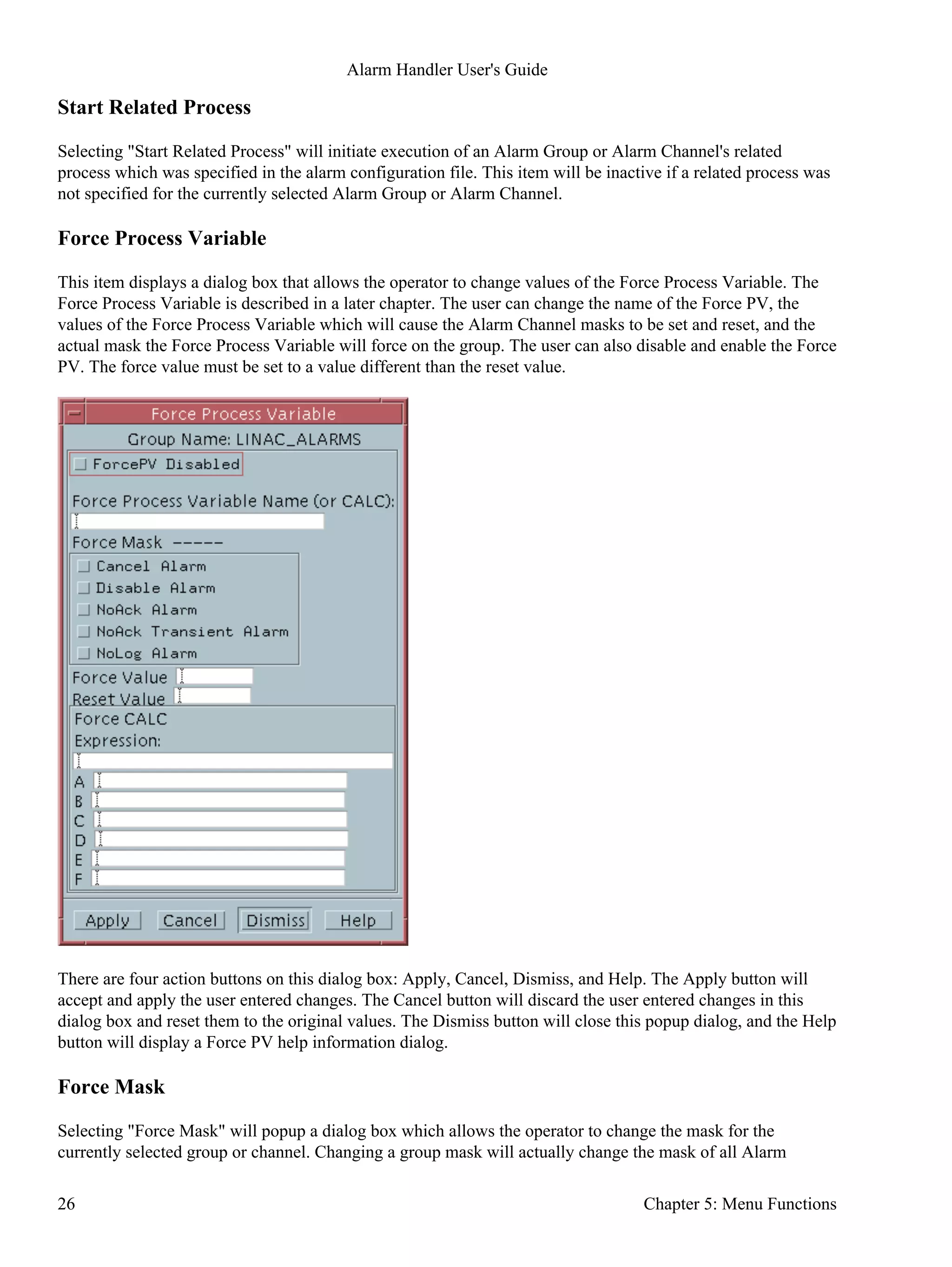
![The fields enclosed in <> are optional.•
Blanks can be used to separate the fields for improved readability.•
The GROUP or CHANNEL line must be first line in a set.•
Lines starting with "#" are comments.•
Lines starting with "$" are optional.•
The [$GUIDANCE ... $END] must be entered as a set if text guidance is present.•
Heartbeat Process Variable
The line starting with $HEARTBEATPV is optional. It is required only when a user wants a monitored pv to
show whether or not ALH is running. If the $HEARTBEATPV line is present, ALH will do CA puts of the
specified value to the specified pv at the specified rate (in seconds). The heartbeatPVName must be an
existing PV in the EPICS database and can be specified as <channel_name>.<field_name>.
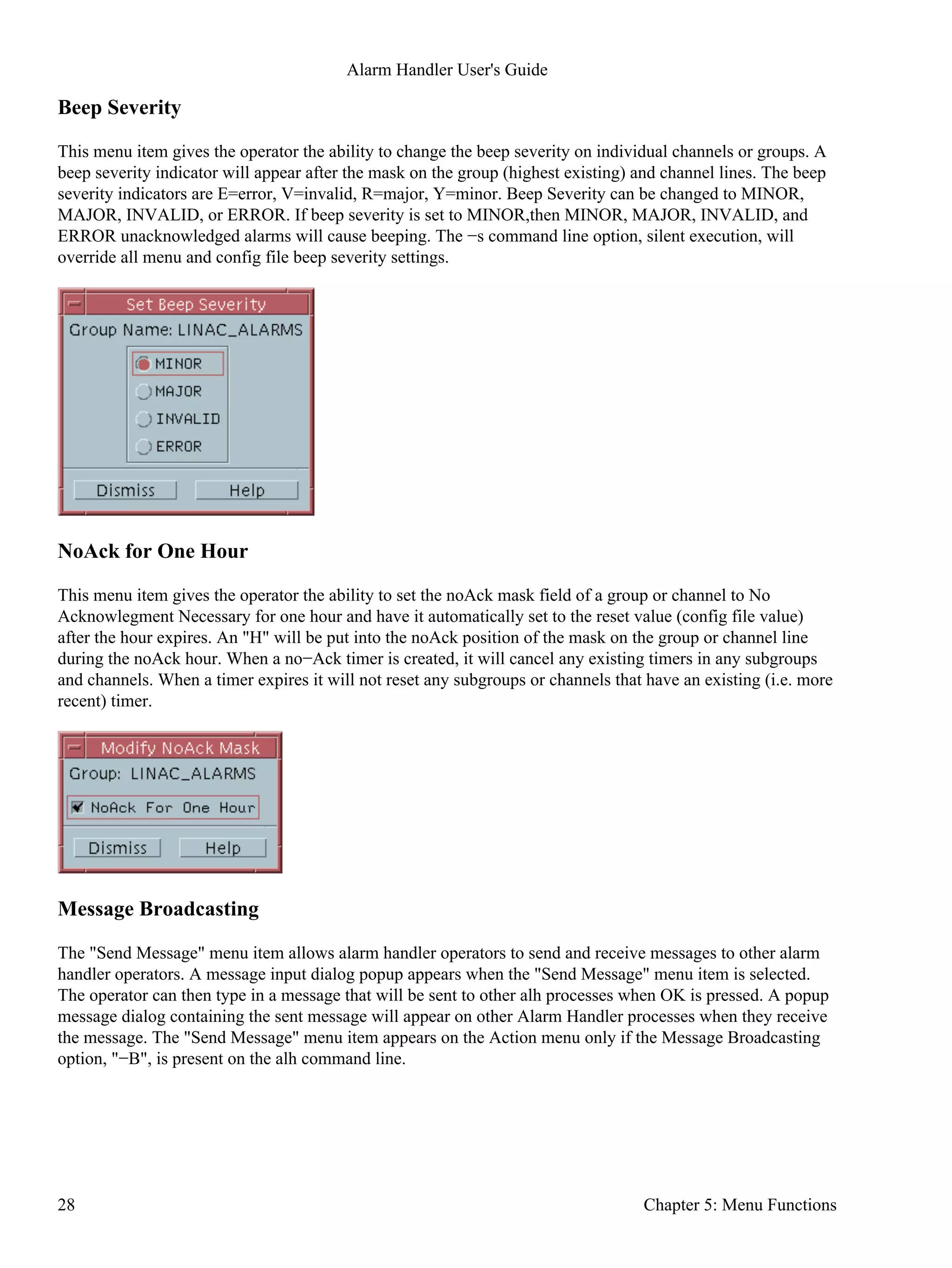
Group or Channel
A set of group or channel lines must appear in the alarm configuration file. These lines define the Alarm
Group structure. The first line is the top level Alarm Group definition. There can be only one top−level Alarm
Group and this Alarm Group must have NULL as the parent group name. Group or Channel lines must start
with the keyword GROUP or CHANNEL. The GroupName is the name of a user specified Alarm Group. The
ChannelName must be the name of a specific record defined in an EPICS database. The parentName is the
name of the parent Alarm Group. There is no restriction on the number of group definitions.
GROUP parentName GroupName
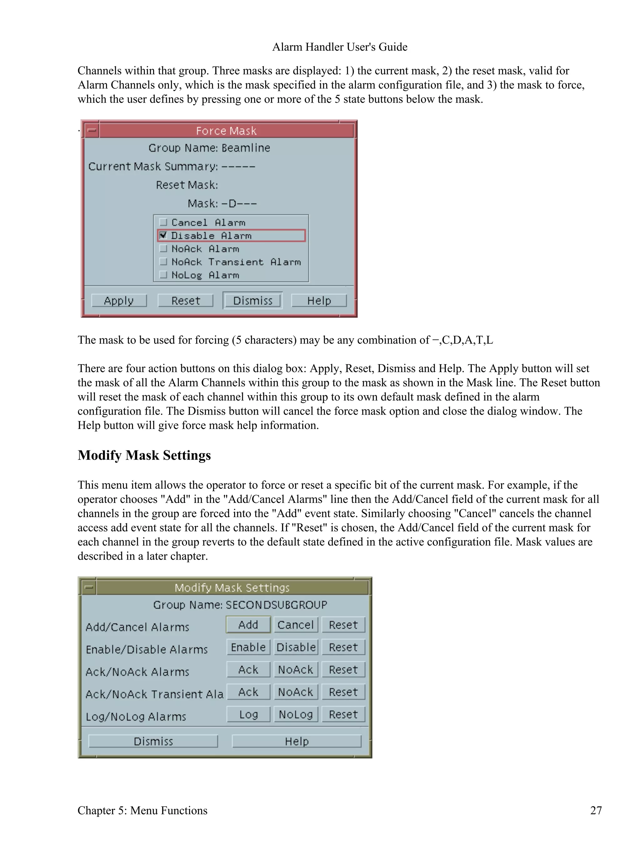
The channel <mask> is optional and defaults to no mask (i.e. −−−−−). It is required only for a channel with a
non default mask setting. The detailed description of mask settings is given in Alarm Channel Mask in this
Chapter.
CHANNEL parentName ChannelName <mask>
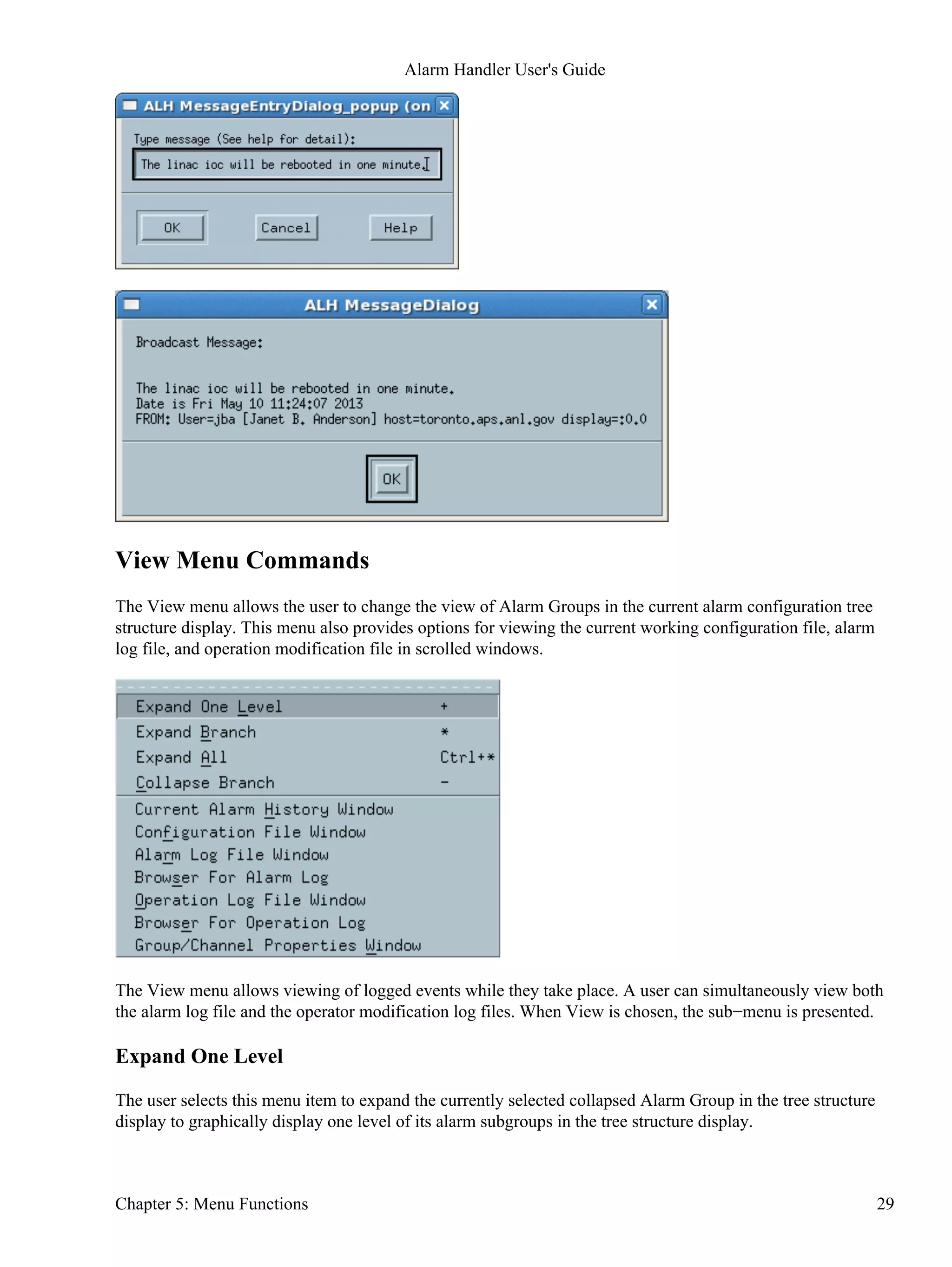
Include File
The line starting with INCLUDE allows a user to designate, within his alarm configuration file, the name of
another alarm configuration file to be read by the Alarm Handler at runtime. The main Alarm Group of the
designated file will become a child group of the parentName group specified on the INCLUDE line.
INCLUDE parentName fileName
Acknowledge Process Variable
The line starting with $ACKPV is optional. It is required only when a user wants to write a user specified
value (ackValue) to an acknowledge process variable (ackPVName) when a channel's alarm is acknowledged.
The acknowledge Process variable must be defined in the IOC database and is specified as
<record_name>.<field_name>. Whenever the channel's alarm is acknowledged, the acknowledge value
(ackValue) is written to the acknowledge process variable via a channel access put (ca_put) request. Writes to
an acknowledge process variable are done only when the alarm handler is in global active mode.
$ACKPV ackPVName ackValue
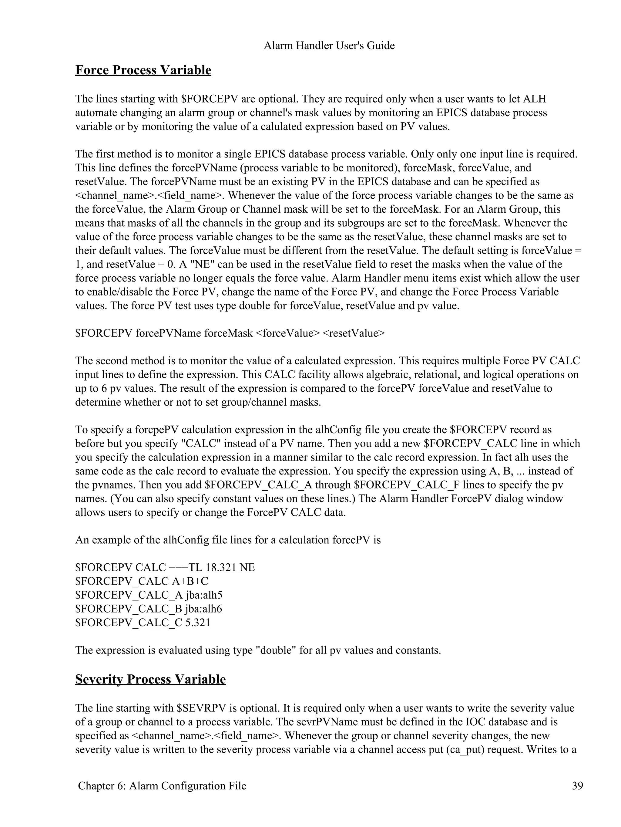
Alarm Handler User's Guide
38 Chapter 6: Alarm Configuration File](https://image.slidesharecdn.com/alhuserguide-1-140627181129-phpapp01/75/ALH-user-guide-1-2-33-May-2013-44-2048.jpg)


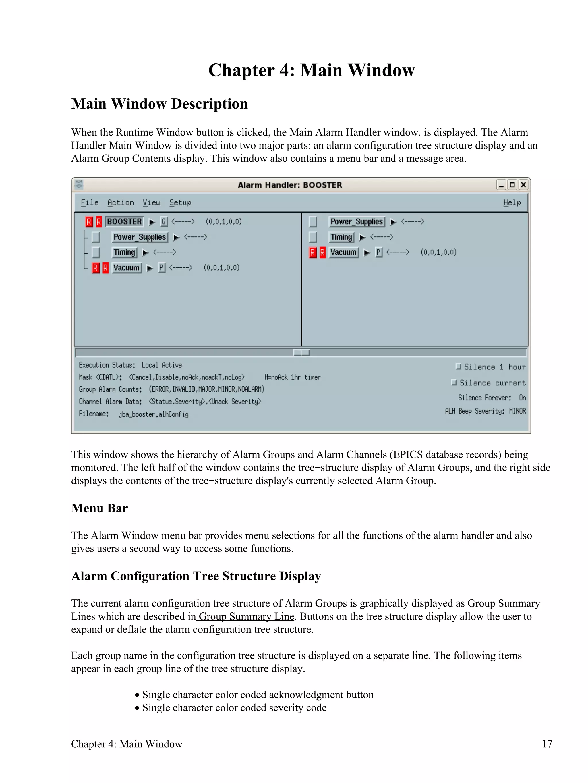
This document provides an overview and user guide for the Alarm Handler system. It describes the purpose and functionality of the Alarm Handler, including definitions of key concepts like alarms, alarm channels, and acknowledgment. It also explains how to start the Alarm Handler and describes the various configuration options, files, and windows involved. The document is organized into multiple chapters covering topics like introduction and terminology, starting the Alarm Handler, and configuration options.


![Guia de identidade visual: [In]Commun Séries](https://cdn.slidesharecdn.com/ss_thumbnails/manual-marca-120929083840-phpapp01-thumbnail.jpg?width=640&height=640&fit=bounds)


